Probably put another 50+ miles on it (filled up again today and put 7 gallons in it).
N/A speed density tune is just about done, I need to switch over and work on the MAF tune some more.
It is a different audible experience with the small turbo and wastegate. Just pushing the pedal while at speed will start the whirl of the turbo spooling up and the wastegate opening, I am glad I put a muffler on the wastegate so it isn't obnoxiously loud.
Drove the car at various speeds in town as well as between 65 and 90 on the interstate and there is zero drone anywhere. The turbo, dual inline mufflers and Helmholtz resonator tube work well. Also got my first thumbs up from a guy on the interstate.
The twin disk clutch is smooth as stock. Easy to modulate, easy to slip, zero chatter or shuddering... I really like it!
Going with a camshaft with slightly less duration, reducing overlap and increasing lift helped increased the low rpm torque, which make the car easier to drive.
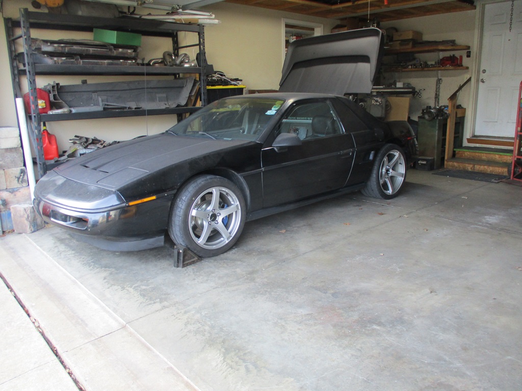
Put the rear decklid on and had to rework the brackets to slightly reposition the front hood prop arm, so now it has a decklid and it stays in the open position.
Put the rear view mirror button back on and the rear view mirror.
Still have a lot more driving as the weather allows and work to put the interior together with the new gauge layout and work on the stereo install.
Looks great. I know you said no drone, but is it quiet enough to leave at 5am without the annoying the neighbors?
What are you going to do once the snow starts falling? Any plans to offer that waterpump setup or is it too labor intensive to market? How about the water manifolds?
Originally posted by KissMySSFiero: Looks great. I know you said no drone, but is it quiet enough to leave at 5am without the annoying the neighbors?
What are you going to do once the snow starts falling? Any plans to offer that waterpump setup or is it too labor intensive to market? How about the water manifolds?
Thanks!
It might still be a smidge loud for 5 am, but I plan to add another boost activate cutout on the driver side. For that one I will modify the butterfly plate (either with holes or trimmed sections of the butterfly) so when closed, it is still 25-50% open. This will allow startup and cruise with the exhaust mostly closed and quieter, but then use exhaust back pressure pre turbo to open it (and the passenger side) when the throttle is mashed.
With the tires on the car, I shouldn't drive it once the temps are below 50 degrees, so it will likely be parked in the garage most of the winter unless I swap over to the 16" wheels. This winter I want to get the 2-Din radio/nav unit installed along with the amp, speakers, sub and review mirror with front and rear cameras. I also want to start working on new front and rear cnc knuckles for the C5 wheel bearings front/rear for the ABS signals needed for my traction control system. But to do those, I have to shift my focus back to the CNC mill and learning Fusion 360 or some other compatible 3D CAD/CAM software.
The water manifold and pump still need some testing in hotter conditions as well as sustained higher rpms and hours of idling. Once that is done, both will need some redesign work and 3D CAD/CAM modeling so they can be made on the CNC mill. The CNC plasma will likely only be used for brackets and not complex parts requiring hours of welding going forward.
Put another 2 hours of drive time on the car while logging VE and then MAF. Got most of the cells dialed in within +/-1%. When I run this tank of gas out, I will fill up with E85. Unfortunately, the air temps are not going to be above 50 for the next 10 days, but that will let me work on the interior vs. tuning.
I will be looking for a go-pro camera during black friday sales so I can start getting better videos of the car in action.
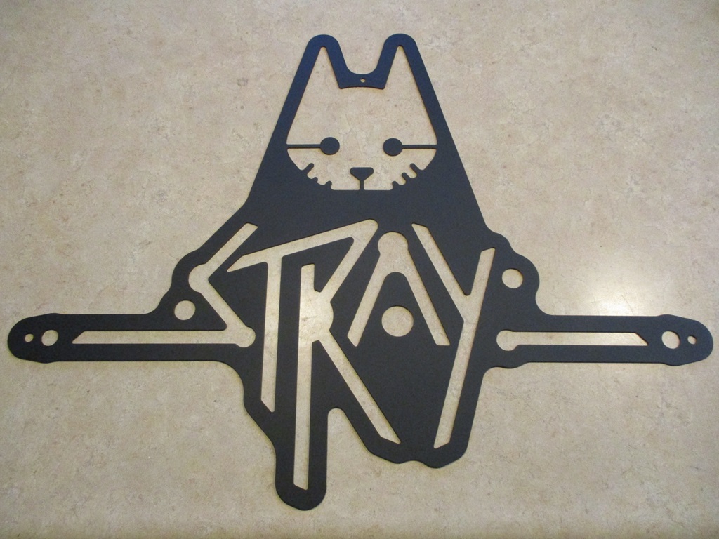
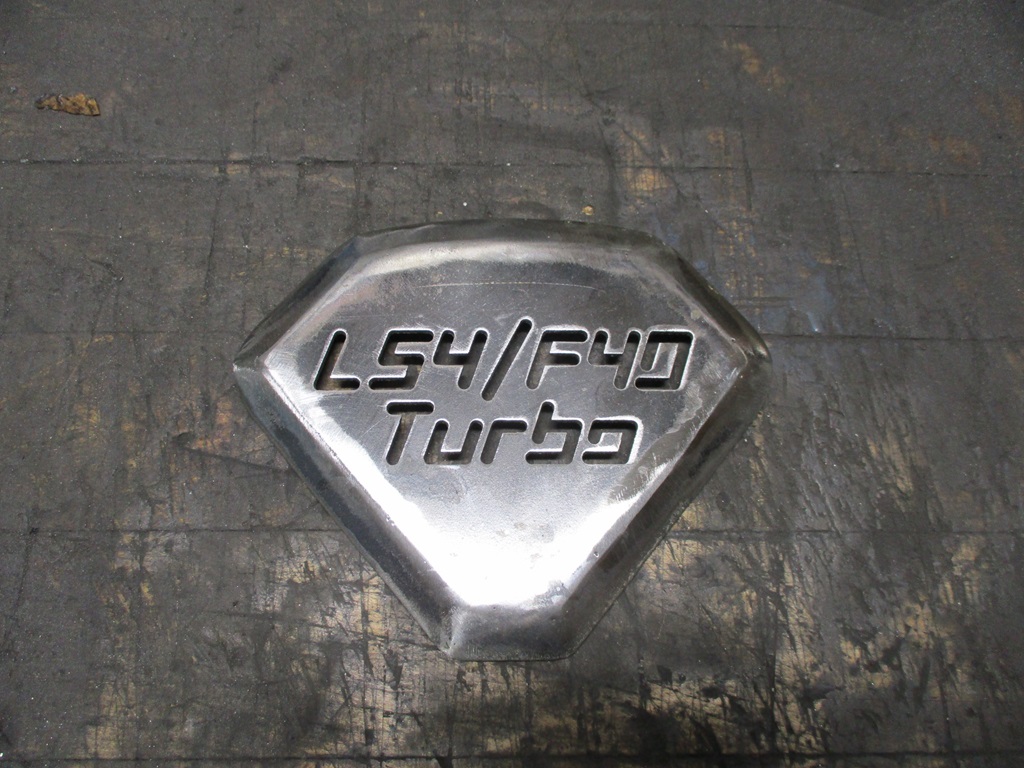
Getting ready for Thanksmas with my side of the family. My mom insisted the gifts for the gift exchange game had to be made and not purchased this year. So I drew this up and cut it out today... It is 8.5" x 13" on 14ga steel.
Put another 2 hours of drive time on the car while logging VE and then MAF. Got most of the cells dialed in within +/-1%. When I run this tank of gas out, I will fill up with E85. Unfortunately, the air temps are not going to be above 50 for the next 10 days, but that will let me work on the interior vs. tuning.
I will be looking for a go-pro camera during black friday sales so I can start getting better videos of the car in action.
Getting ready for Thanksmas with my side of the family. My mom insisted the gifts for the gift exchange game had to be made and not purchased this year. So I drew this up and cut it out today... It is 8.5" x 13" on 14ga steel.
Since it has been in the 30s and now 20s over night, I started taking parts of the car apart to address minor things.
The drain line to from the turbo was leaking, so I pulled the tube and fittings to rework them. To get to the two bolts holding the drain housing to the turbo, I went ahead and dropped the exhaust (resonator tube in the way). To drop the exhaust, I had to rock the cradle back about 6". Rocking the cradle back for access is something I planned for in the swap layout and all it takes is loosing the front cradle bolts and removing the 2 rear cradle bolts. Everything else has clearance and range of motion for the cradle tip.
I went ahead and removed the boost signal stainless lines from the wastegate, charge pipe, and manual controller. Instead, I ran three 1/4" nylon lines into the passenger compartment. I have a manual boost controller knob (more about this later) and 2 of the 3 lines will be used for it. The 3rd line goes to the wastegate dome and is for future use with an electronic boost controller... if I want to switch from the manual one.
This was also a good opportunity to install the bulk head housing to the harness.
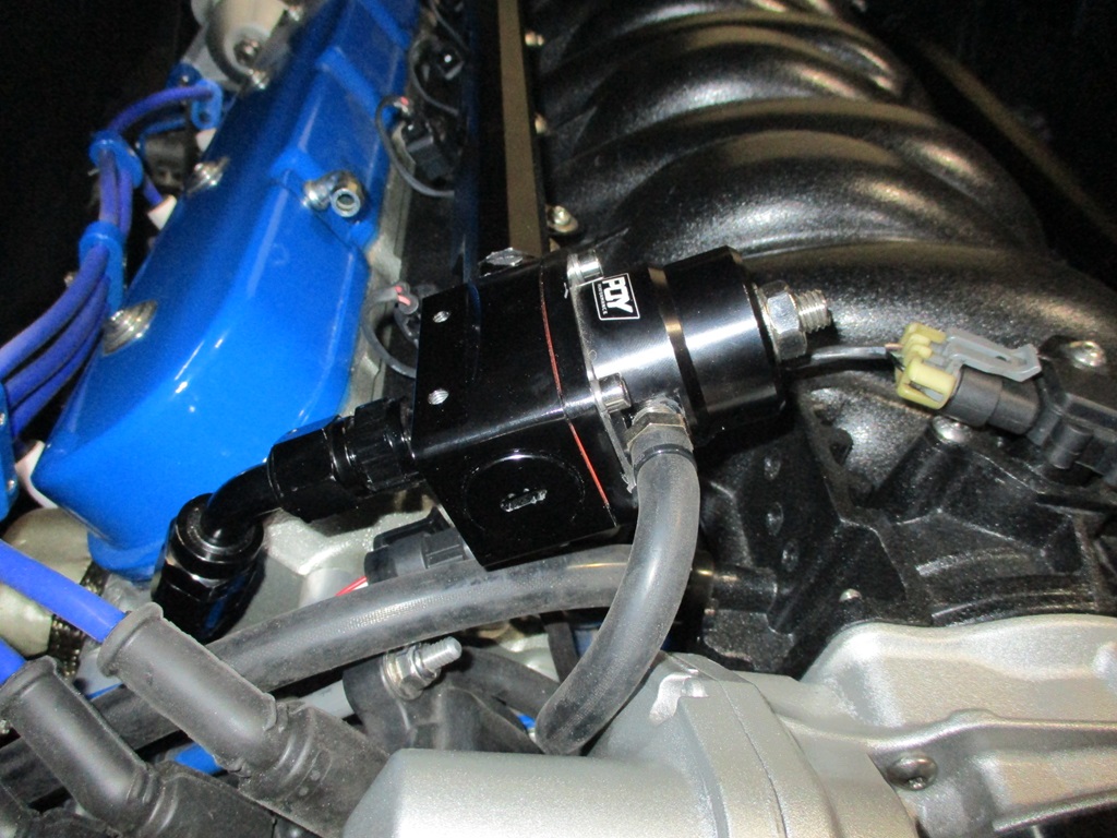
The pressure sender on the fuel regulator was also annoying me, so off came the fuel rails and regulator so I could disassemble the regulator and reassemble it to allow the pressure sender to be on the bottom hidden side. Much better!
Then I started messing with the interior.
I have a smart rear view mirror with back camera, front camera, and GPS antenna to install. The radio receiver also has GPS antenna as well as a back up camera. So I need to run some wires up the driver A-pillar and through the car to the rear. Planning for the backup camera wires to pass through the grommet for the parking brake cable, so out came the drivers seat, door opening trim, and the carpet. The dash is next to be removed...
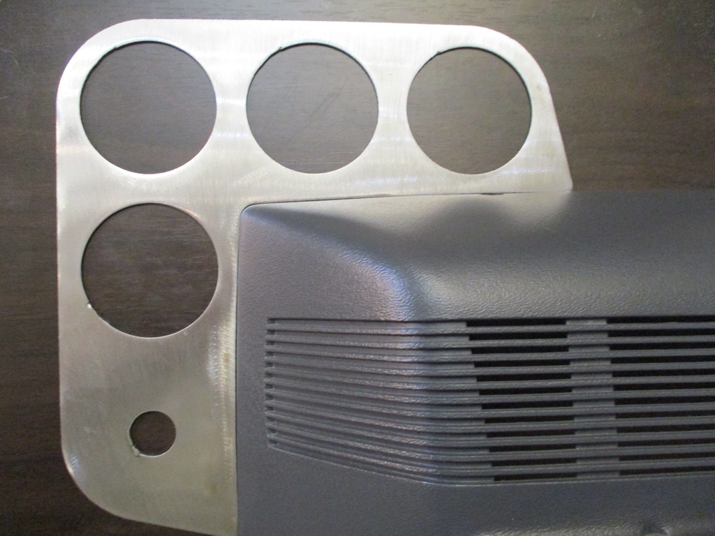
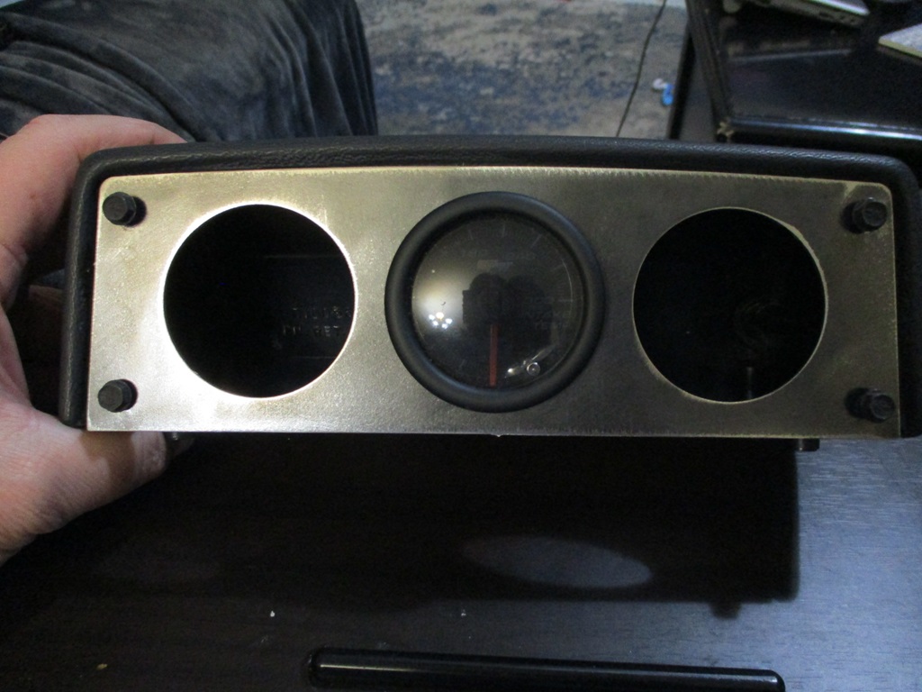
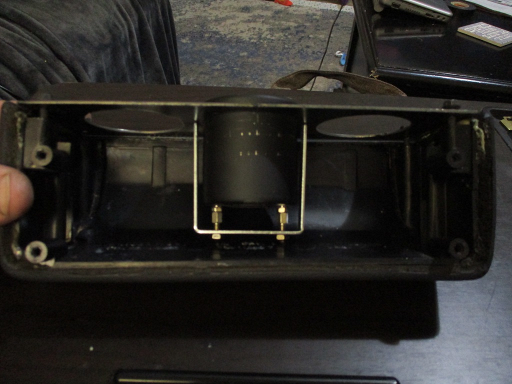
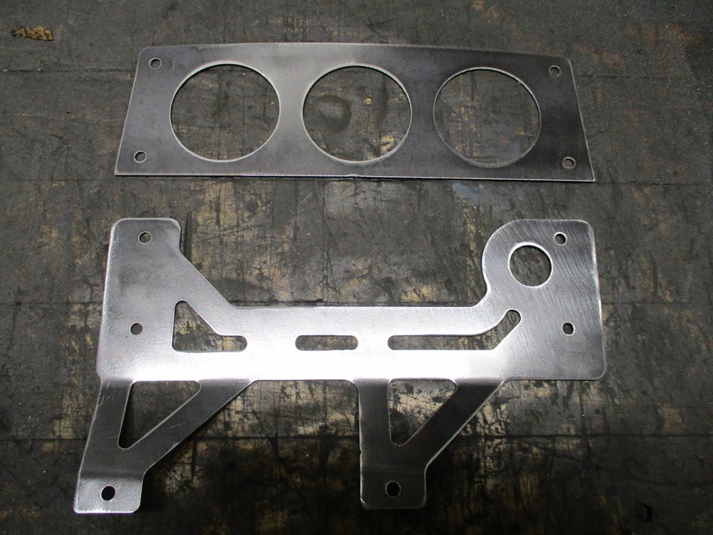
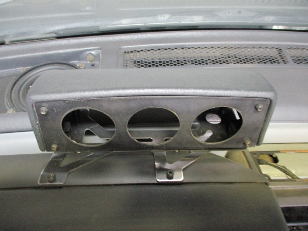
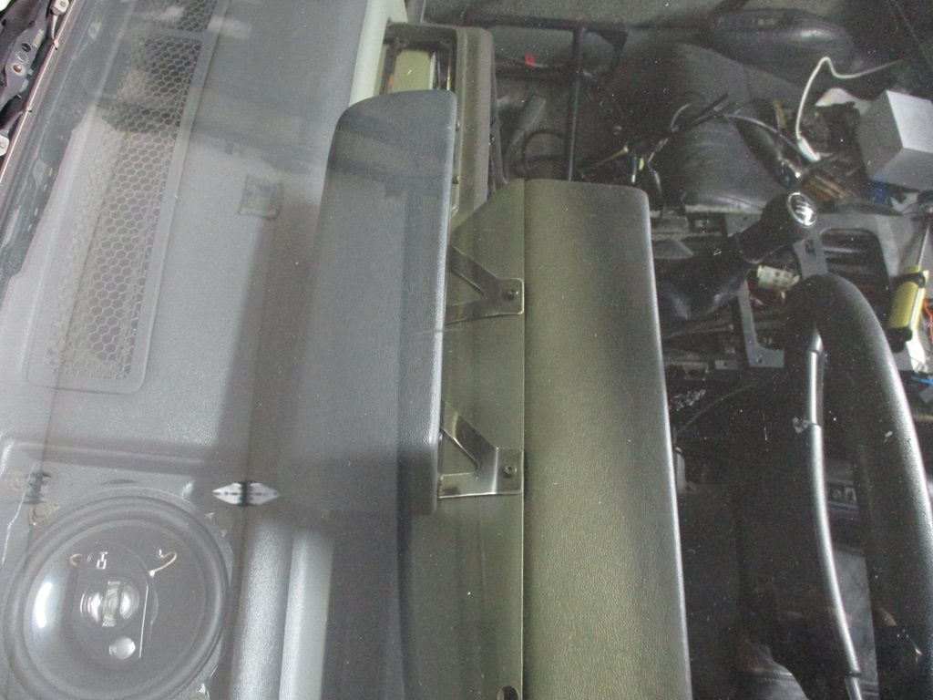
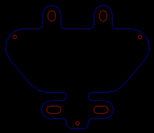
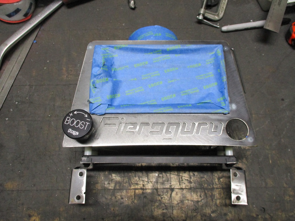
Before the dash comes out, I want to get the gauge pod better figured out. The current plan is to have the face of the gauge pod further forward, basically right at the seam between the cluster housing and the front cover. So brought the cover up from the basement and started taking some measurements and cut the first prototype out. This first part is very, very close to matching the cover contour: Here is the side that will face toward the front of the car:
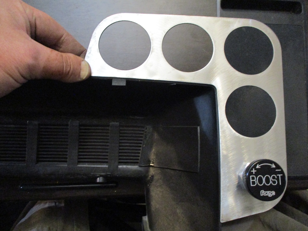
Here is the side that will face the driver (it also shows the location of the manual boost adjustment knob):
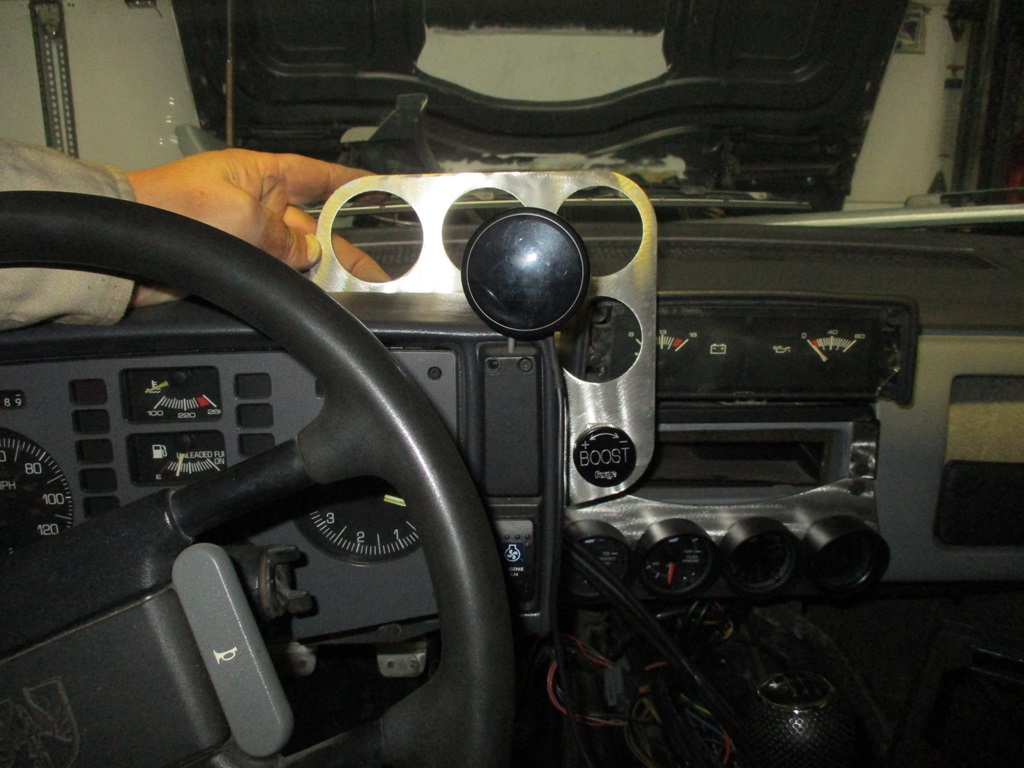
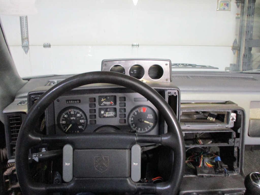
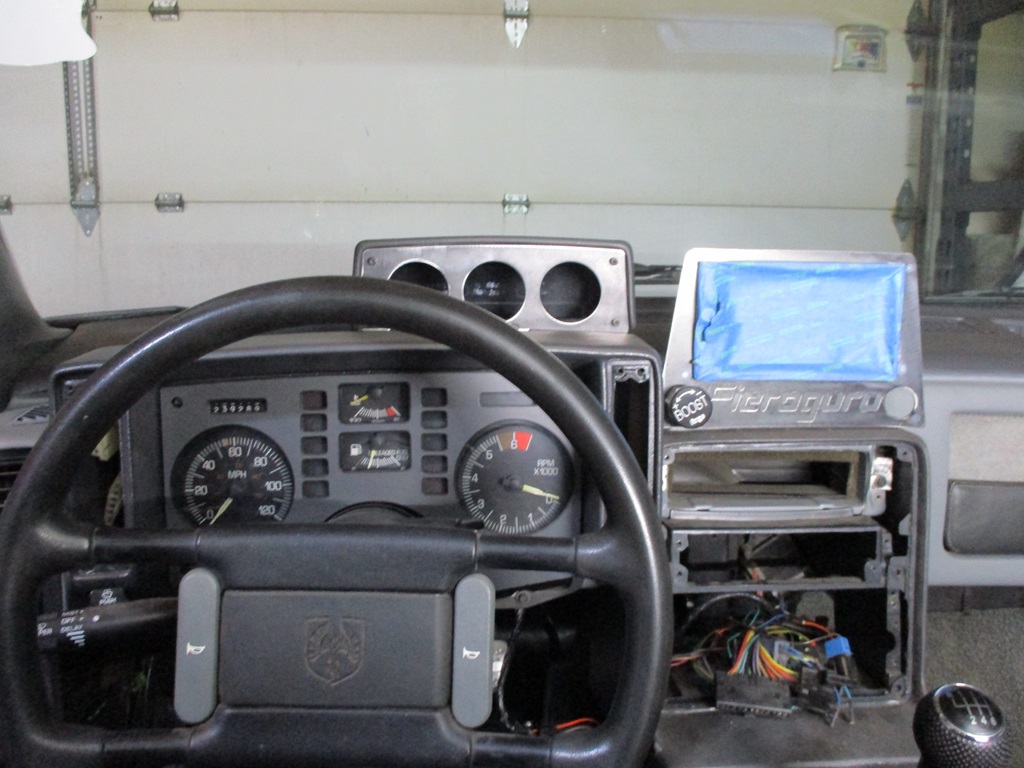
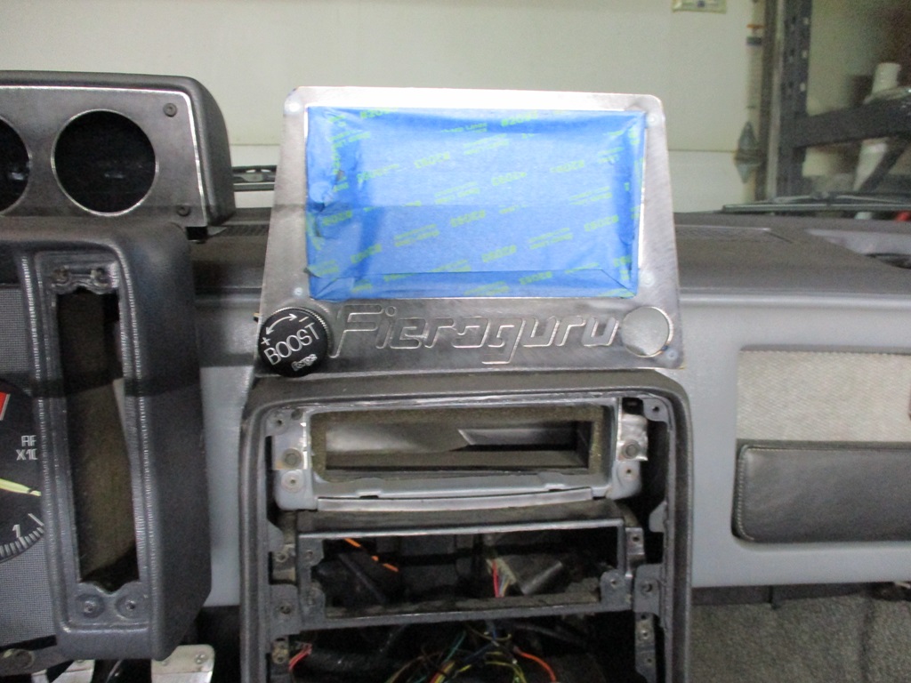
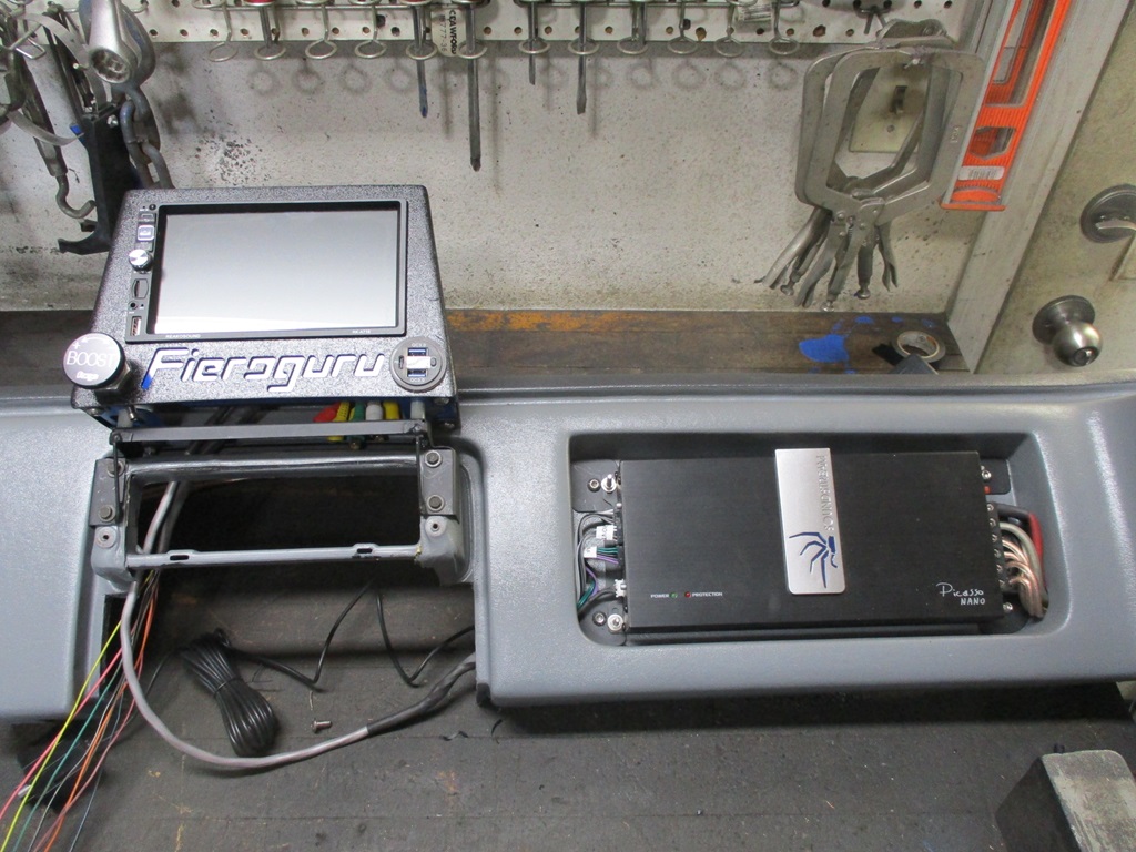
Here is a general look in the car. I need to set the seat back in so I can better mock up this gauge location from the driver seat to see how much of the new radio (mounted where the aux gauges are) will be obscured. I can shift the radio slightly to the passenger side if needed.
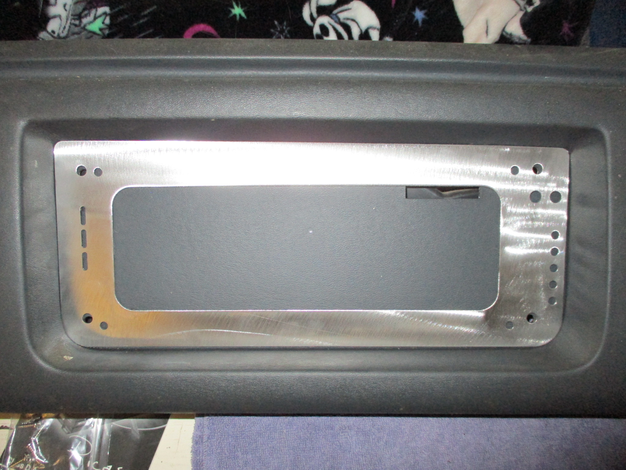
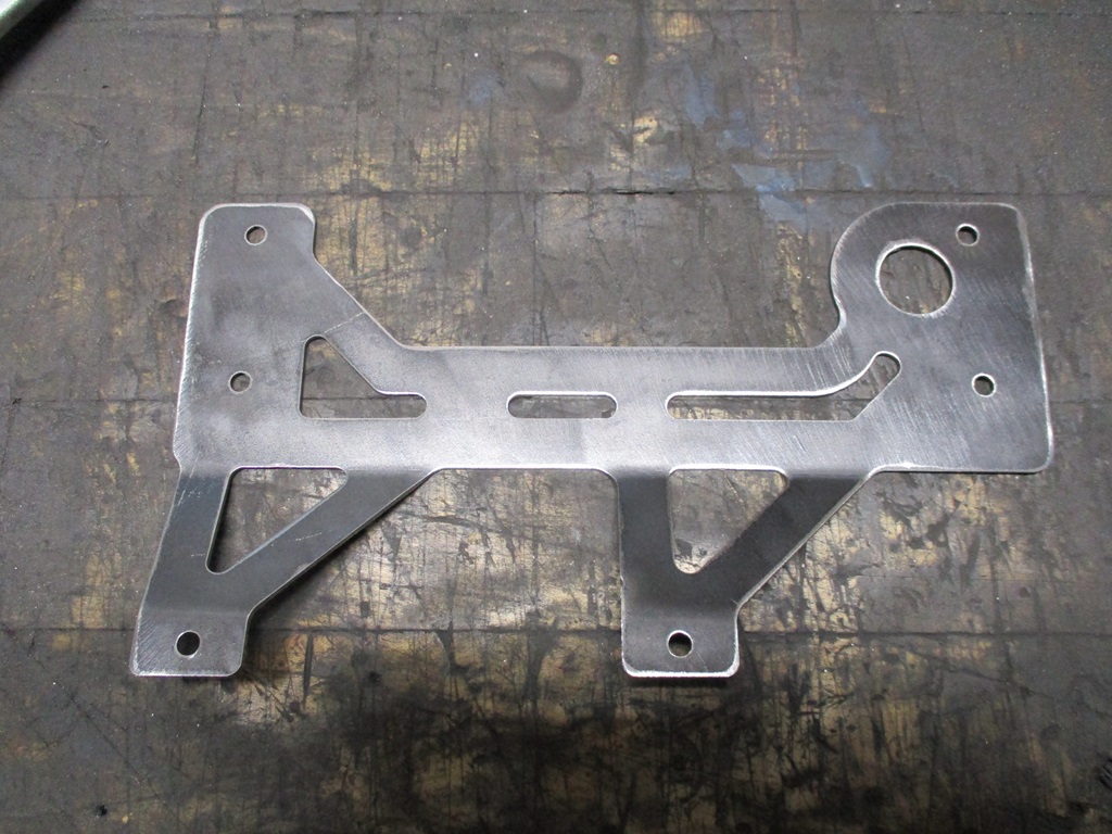
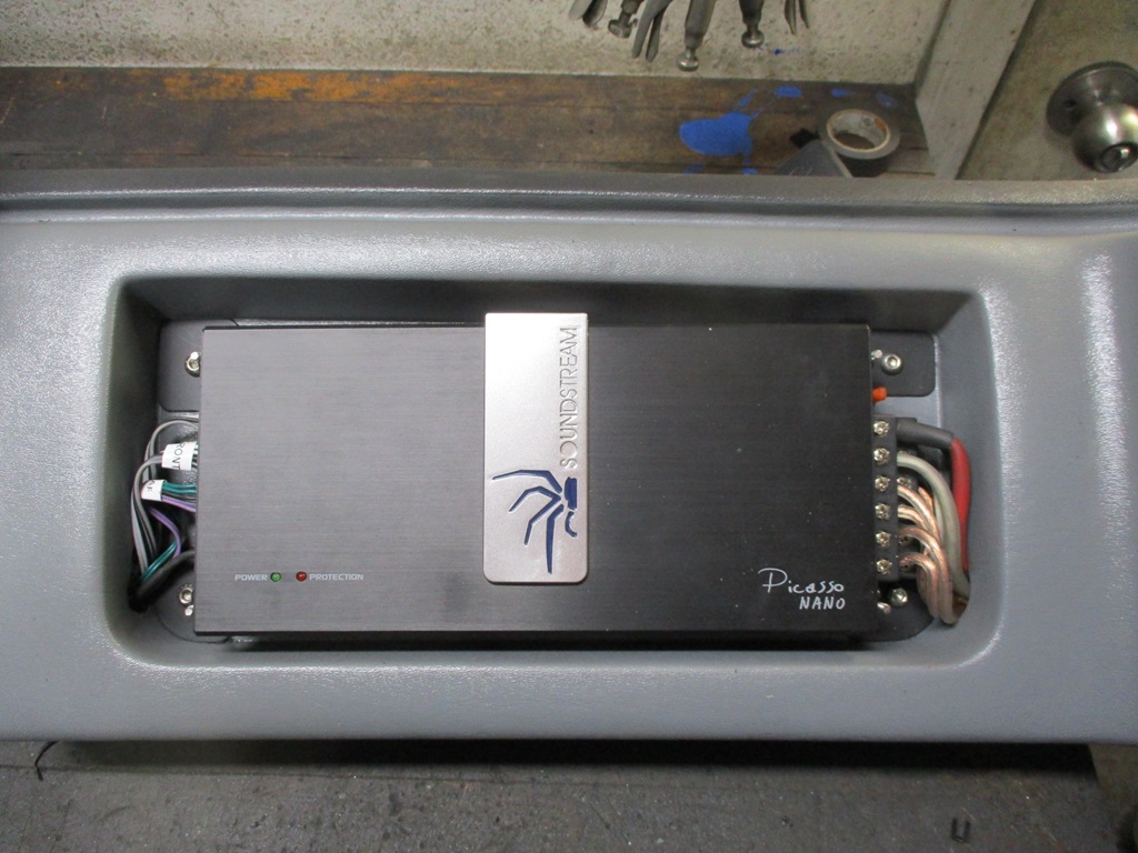
While I was drawing up the gauges, I also pulled the spare dash from the basement and started detailing out the base plate that will allow mounting the amp in the map pocket recess. This is the first one, so it still need some slight refinement (1/16" less length, sligntly larger radii at the bottom, move the location of the top mounting holes about 1/16" so significantly improve the fitment.
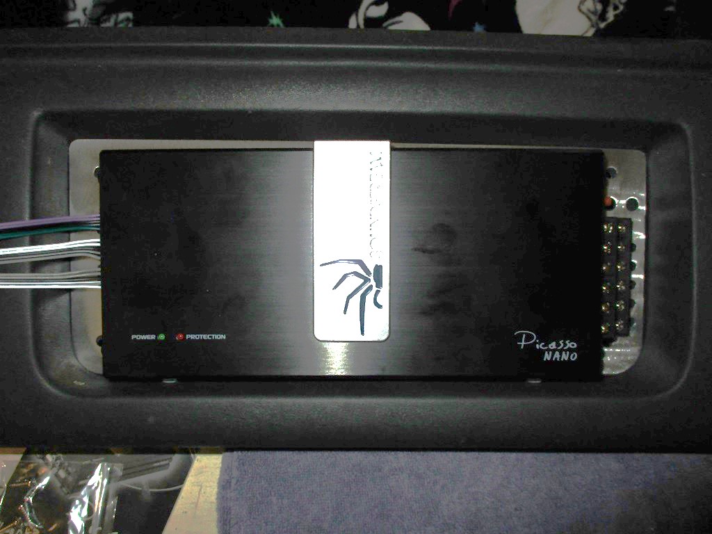
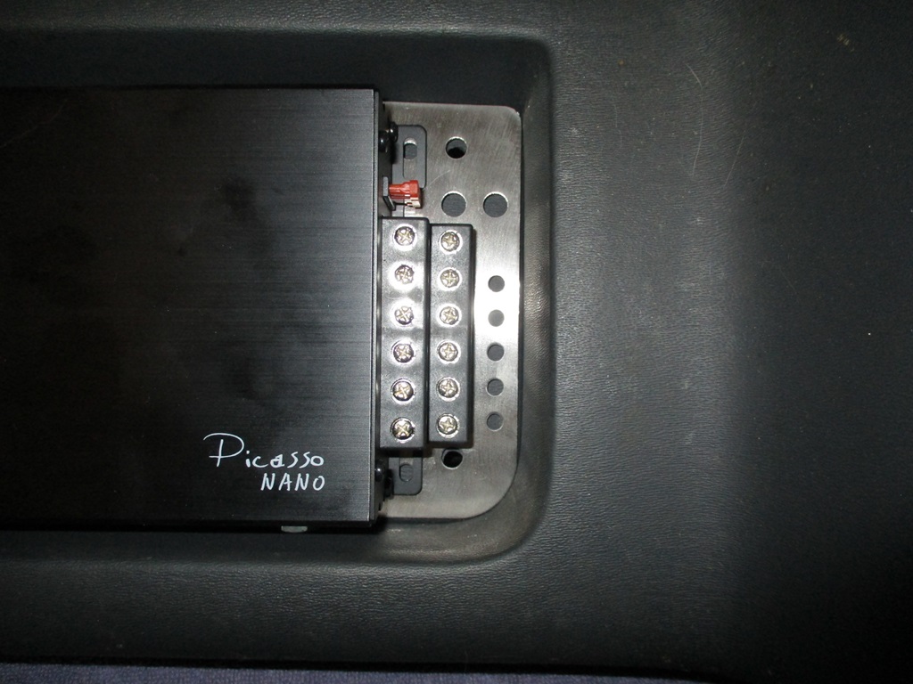
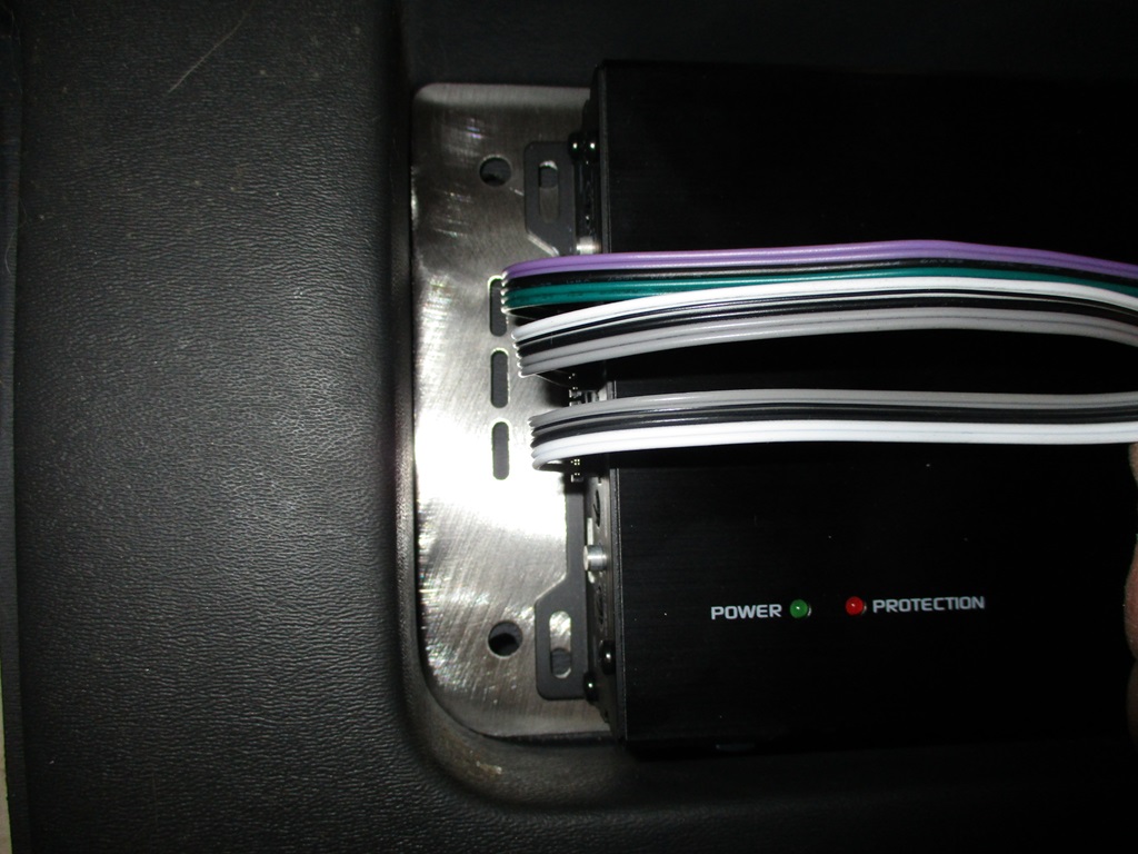
Here is the amp in the general location. All the wires will drop through the holes in the plate and exit out from the backside of the dash. I might even make a flush face trim ring to fill in the gaps...
Congrats on getting it running and out on the road!
quote
Originally posted by fieroguru:
Bled the clutch - twin disk clutch seems to be releasing and the HTOB didn't overextend, so that was good! Won't be able to test it further until the engine runs.
quote
Originally posted by fieroguru:
The twin disk clutch is smooth as stock. Easy to modulate, easy to slip, zero chatter or shuddering... I really like it!
Which clutch are you using? Is there a post where you discussed it?
Which clutch are you using? Is there a post where you discussed it?
McLeod RTS 91/2" twin disk clutch, organic disks, with some slight modifications. It is a super tight fit.
This post is on page 46.
quote
Originally posted by fieroguru:
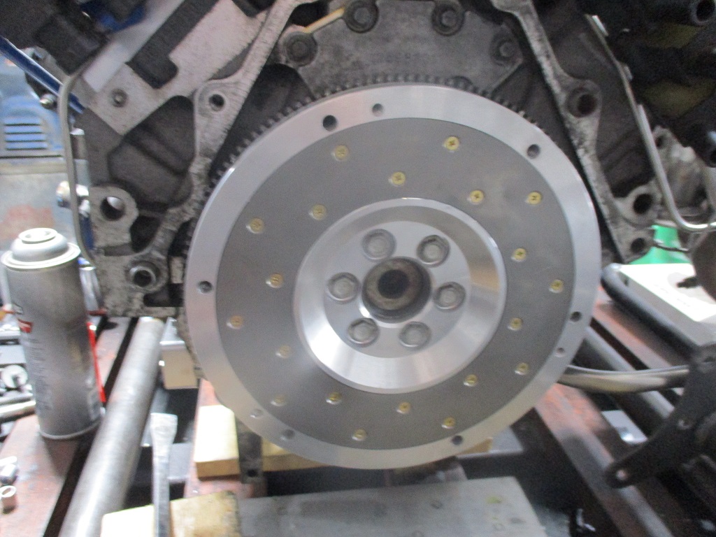
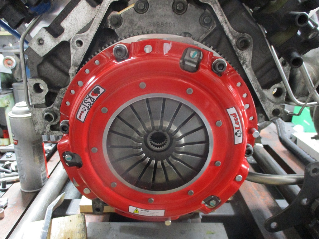
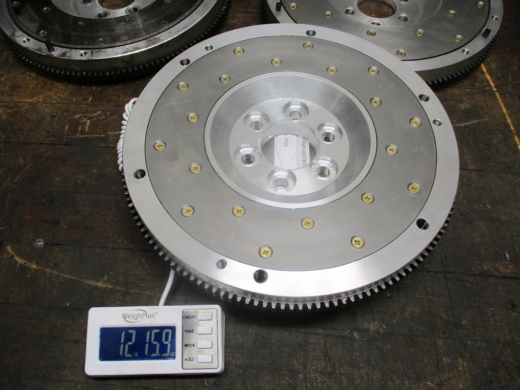
Flywheel and twin disc clutch are now done.
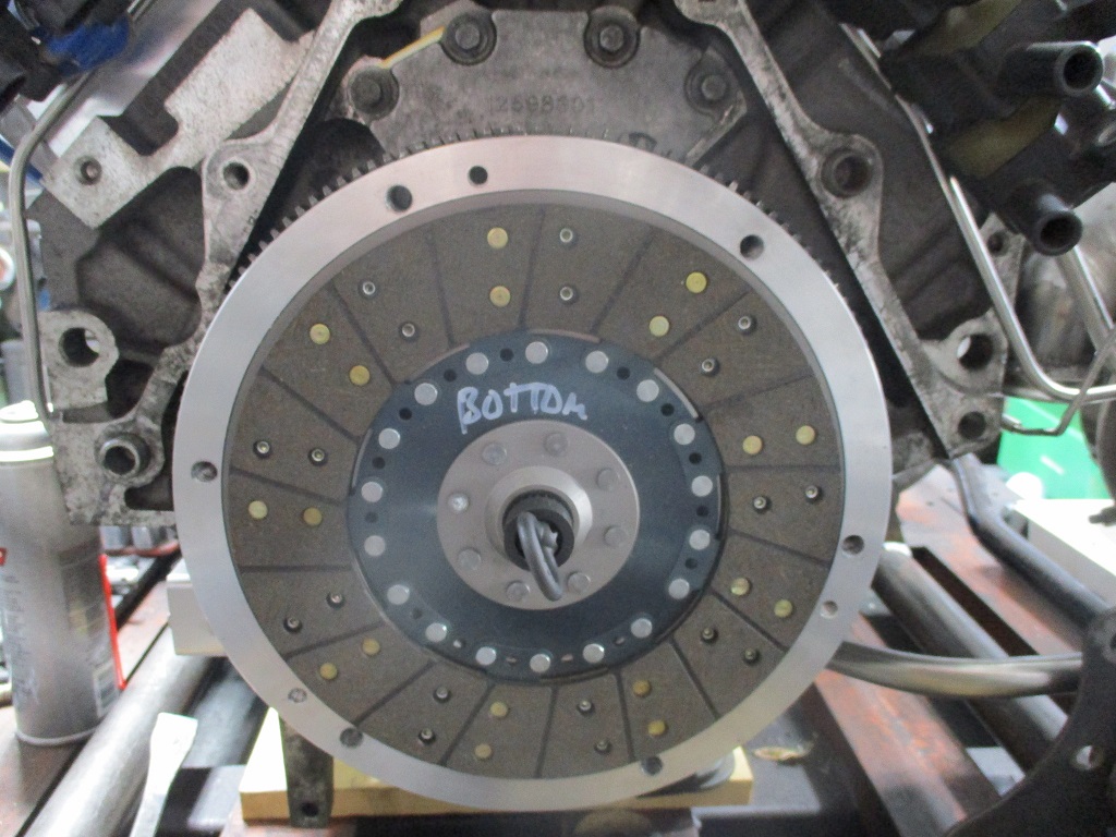
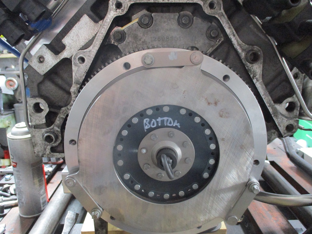
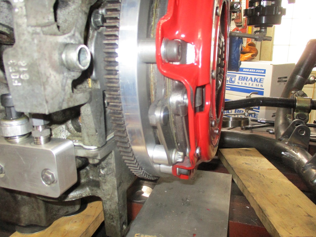
Sequence of installation Flywheel: Bottom Disc: Floater Plate: For some reason I missed taking a picture of the top disk.
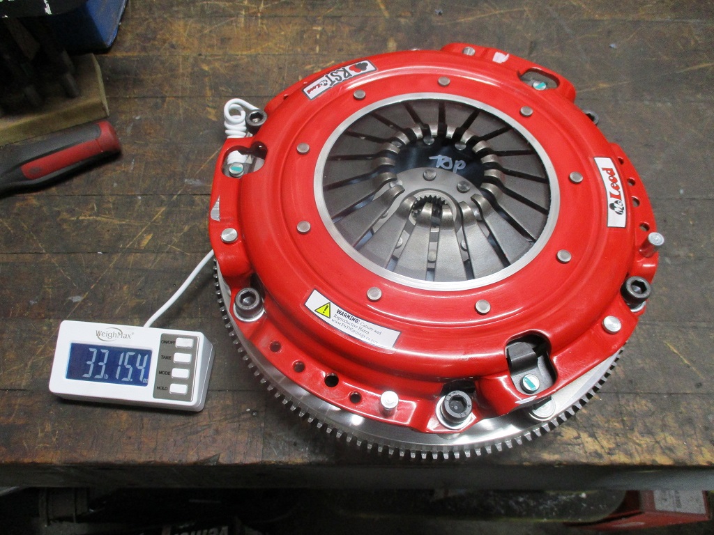
Pressure plate: Transmission installed:
With my quest for weight offsetting for the turbo bits, the twin disc clutch is definitely heavier than my last setup. However, like the turbo, the additional weigh is needed to hold up to 800 hp while keeping the car daily driver friendly, but the additional weight was still kept to a minimum.
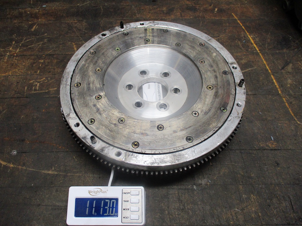
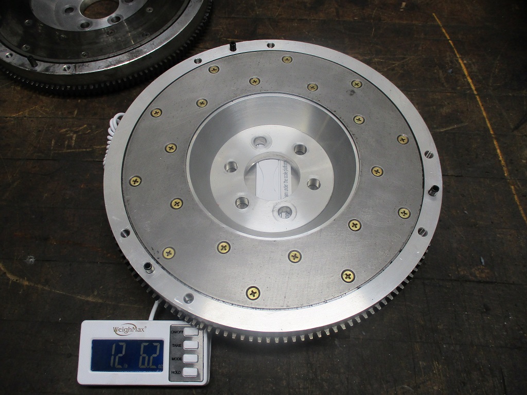
For comparison, a stock 2.8 fiero setup is about 15 lbs for the flywheel and 15.6 lbs for the clutch/pressure plate = 30.65 lbs. LS4/F40 Spec Stage 4+ combo is 11.2 lbs for the flywheel and 28 lbs total after 55K miles of use. Stock 2000 LS1 is 24 lbs for the flywheel and 32 lbs for the clutch/pressure plate = 56 lbs and this weight is spread over a 2" larger diameter. LS4/F40 flywheel/twin disc clutch combo is 13 lbs for the flywheel, and 21 lbs for the clutch discs, floater plate, pressure plate and all bolts. = 34 lbs So the setup will be about 3.5 lbs heavier than stock Fiero and 22 lbs lighter than a stock LS1 clutch setup.
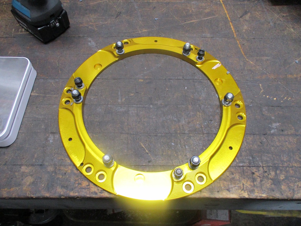
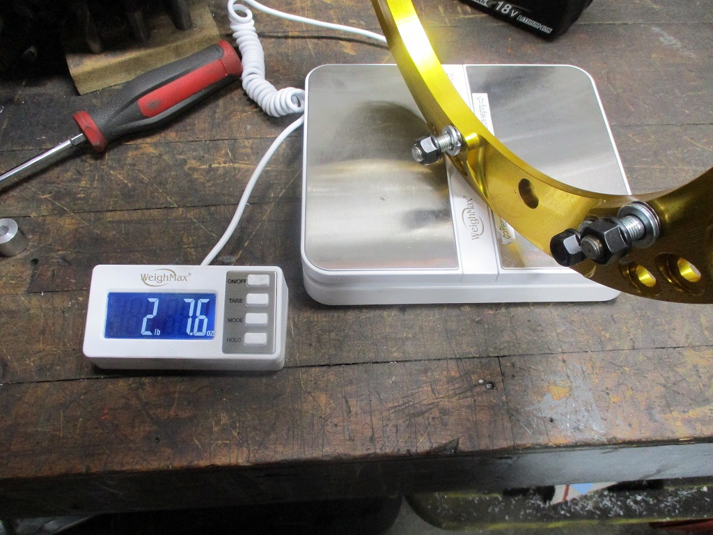
The clutch did come with this plate so that it could reuse the stock flywheel/pressure plate bolt patterns... I tossed it as it wasn't needed. This saved 2.5 lbs off the clutch kit as delivered.
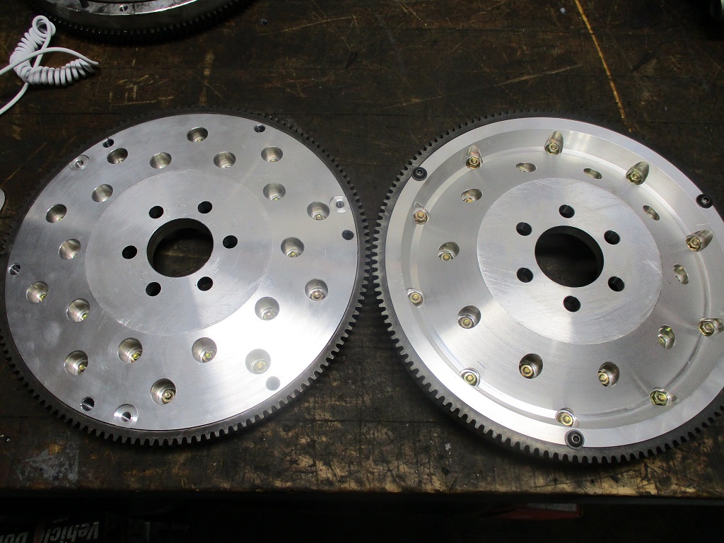
Here is a history of my LS4 flywheels: Original prototype (after 55k miles) - fabricated with manual lathe and mill:
CNC version of original from small batch run:
Protype of the twin disc version - fabricated with manual lathe and mill:
The twin disc version is heavier as there is minimal material taken off the backside:
Now it is pretty much time to start cleaning things, sand blasting them and starting to make then look pretty.
McLeod RTS 91/2" twin disk clutch, organic disks, with some slight modifications. It is a super tight fit.
This post is on page 46. [QUOTE]Originally posted by fieroguru:
Flywheel and twin disc clutch are now done.
Sequence of installation Flywheel: Bottom Disc: Floater Plate: For some reason I missed taking a picture of the top disk.
Pressure plate: Transmission installed:
With my quest for weight offsetting for the turbo bits, the twin disc clutch is definitely heavier than my last setup. However, like the turbo, the additional weigh is needed to hold up to 800 hp while keeping the car daily driver friendly, but the additional weight was still kept to a minimum.
For comparison, a stock 2.8 fiero setup is about 15 lbs for the flywheel and 15.6 lbs for the clutch/pressure plate = 30.65 lbs. LS4/F40 Spec Stage 4+ combo is 11.2 lbs for the flywheel and 28 lbs total after 55K miles of use. Stock 2000 LS1 is 24 lbs for the flywheel and 32 lbs for the clutch/pressure plate = 56 lbs and this weight is spread over a 2" larger diameter. LS4/F40 flywheel/twin disc clutch combo is 13 lbs for the flywheel, and 21 lbs for the clutch discs, floater plate, pressure plate and all bolts. = 34 lbs So the setup will be about 3.5 lbs heavier than stock Fiero and 22 lbs lighter than a stock LS1 clutch setup.
The clutch did come with this plate so that it could reuse the stock flywheel/pressure plate bolt patterns... I tossed it as it wasn't needed. This saved 2.5 lbs off the clutch kit as delivered.
Here is a history of my LS4 flywheels: Original prototype (after 55k miles) - fabricated with manual lathe and mill:
CNC version of original from small batch run:
Protype of the twin disc version - fabricated with manual lathe and mill:
The twin disc version is heavier as there is minimal material taken off the backside:
Now it is pretty much time to start cleaning things, sand blasting them and starting to make then look pretty.
[/QUOTE]
Ahh, cool. Thanks!
I have a PowerTrain Technology 7.25" dual disk. They list organic disks, but really don't want to sell them. It's weird. They steered me toward a unit with the thinner cerametallic disks. That's ok with me, as it let me package the assembly inside a 282 bellhousing without making a flywheel from scratch. We'll see how easy or otherwise it is to drive.
How does the throw out distance compare to the F40 HTOB range or to a stock clutch?
[This message has been edited by Will (edited 12-13-2023).]
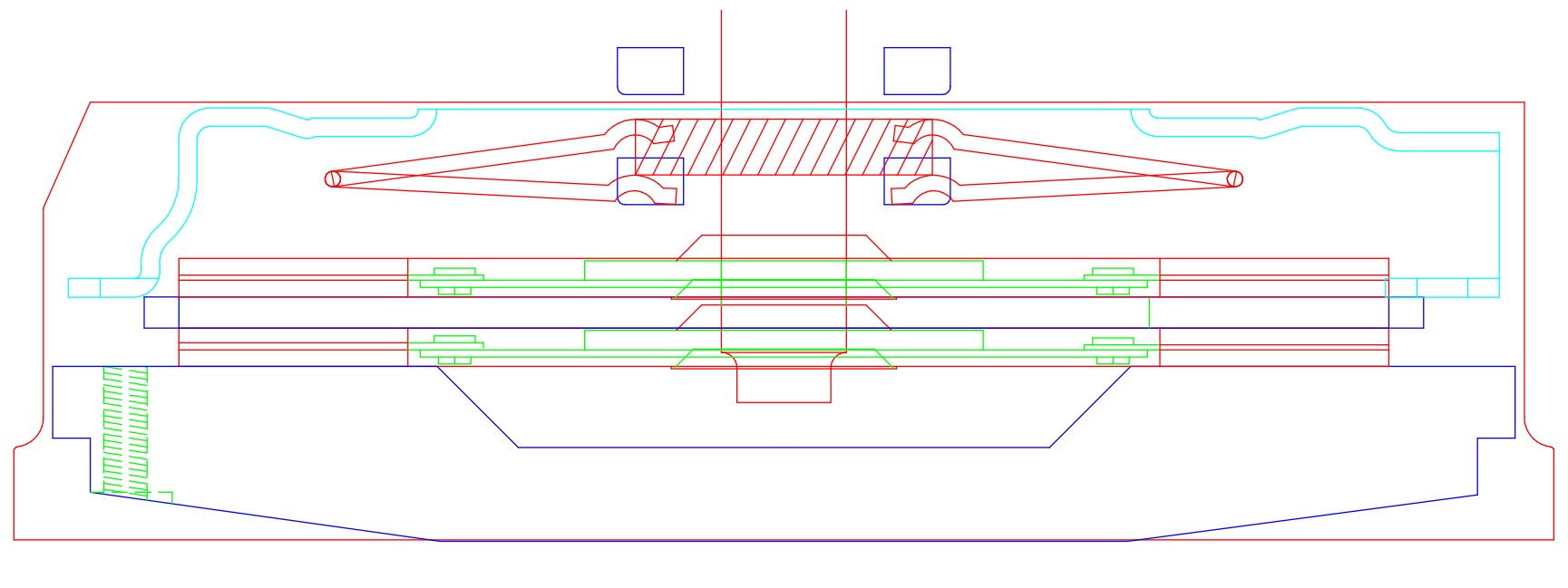
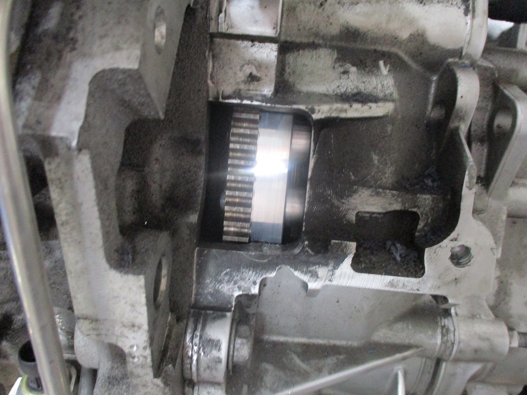
Originally posted by Will: How does the throw out distance compare to the F40 HTOB range or to a stock clutch?
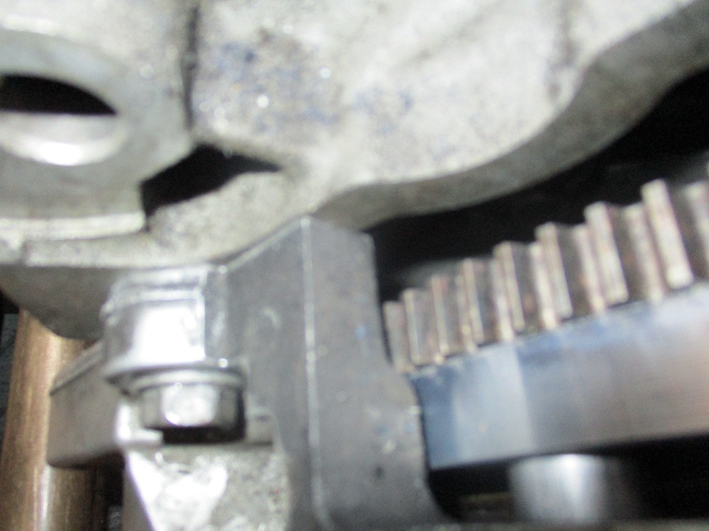
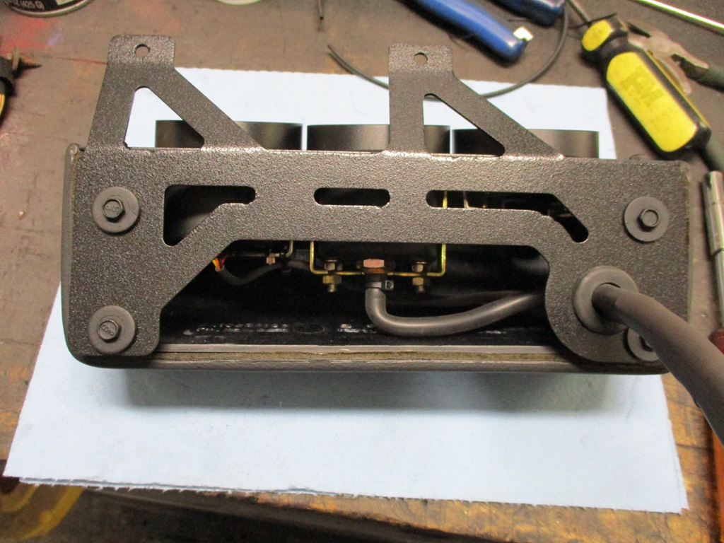
In this layout the 4 rectangular blocks in the upper center represent the F40 HTOB at full compression and full extension.
The positions of the pressure plate fingers are with the pressure plate bolted into position and the recommended throw to release the clutch. I spent a fair amount of time dialing in the thickness of the flywheel to ensure full spline engagement on the discs and in combination with the height of the flywheel to pressure plate spacers to position the pressure plate fingers optimally. Release is about 1/2 pedal travel and the clutch starts moving the car from a stop with the pedal about 1" off the floor. I have a Rodney clutch master with adjustable banjo and my clutch pedal is pretty much flush with the brake. I could adjust the clutch pedal higher.
When I start driving the car to work in the spring, I will likely have to leave my work boots at work and change into them at work. Size 13E work boots are a little snug with the pedals. Right foot barely fits past the brake pedal and console area to reach the loud pedal. Left foot on the clutch rubs the wheel well carpet quite a bit as well. My normal shoes work much better.
does the car smoke under hard acceleration while driving? Blue smoke? I'm just curious if the turbo can scavenge the oil without backing up. I love the way it sounds nice design.
does the car smoke under hard acceleration while driving? Blue smoke? I'm just curious if the turbo can scavenge the oil without backing up. I love the way it sounds nice design.
Thanks! No smoke (blue or otherwise) once I got the tune dialed in.
It will be a few more weeks before I am back working on the car... The Saturday before Christmas I sprained my left ankle really bad falling down some steps. Dr. says I need to let it heal and wear a boot for the next several weeks, which will limit my garage time for a bit.
I did need to finish something before Christmas, so I hobbled around in the garage long enough to finish this for Sara!
My ankle is getting better... On Wednesday this week the boot was trades for an ankle brace and now I am back wearing my normal shoes/boots.
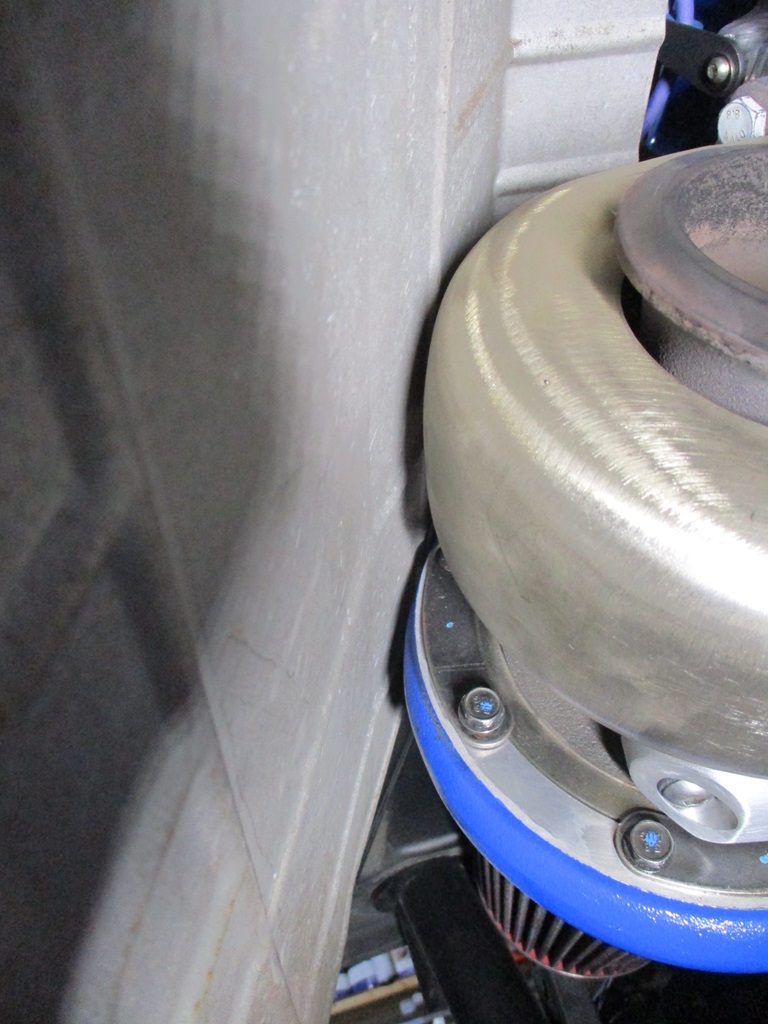
Here is a picture with the heat shield installed from last weekend. It has about 1/8" gap to the compressor as well as to the turbine heat shield.
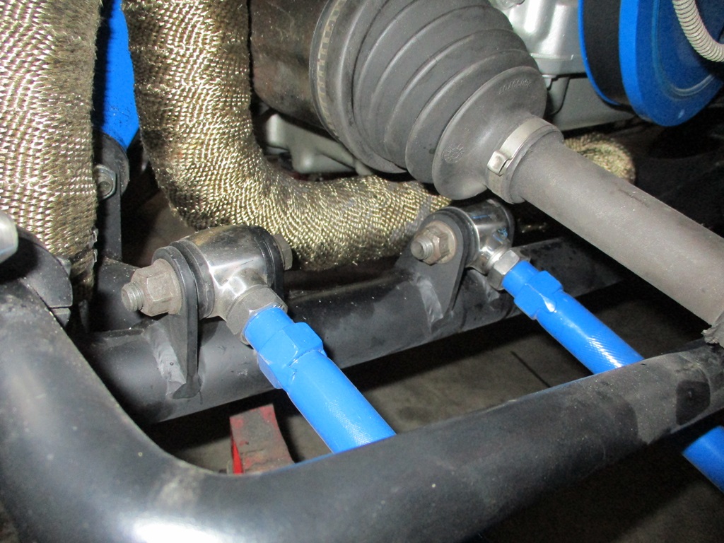
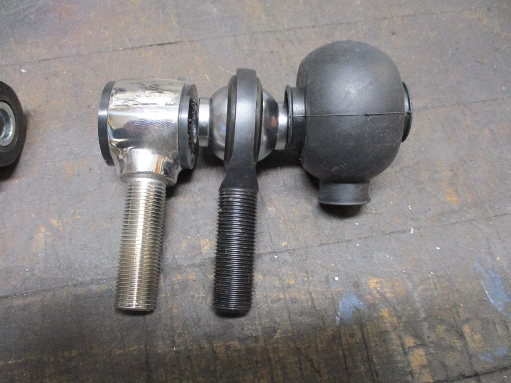
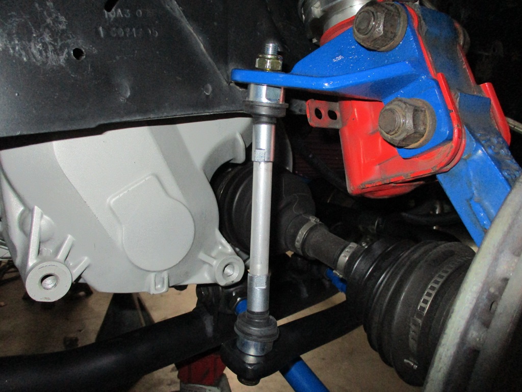
Worked on the lateral links and sway bar links this weekend. I tried some new poly ends from Speedway motors earlier this year. They looked awesome, but the lateral links move to much front to rear as the suspension cycles, so they were binding and needed to be replaced before one snapped. At least 1 of them was bent when removed, so perfect timing. The driver side ones were pulled and rod ends put back in, but with a rubber boot this time. We will see if I they last more than 10K miles this time.
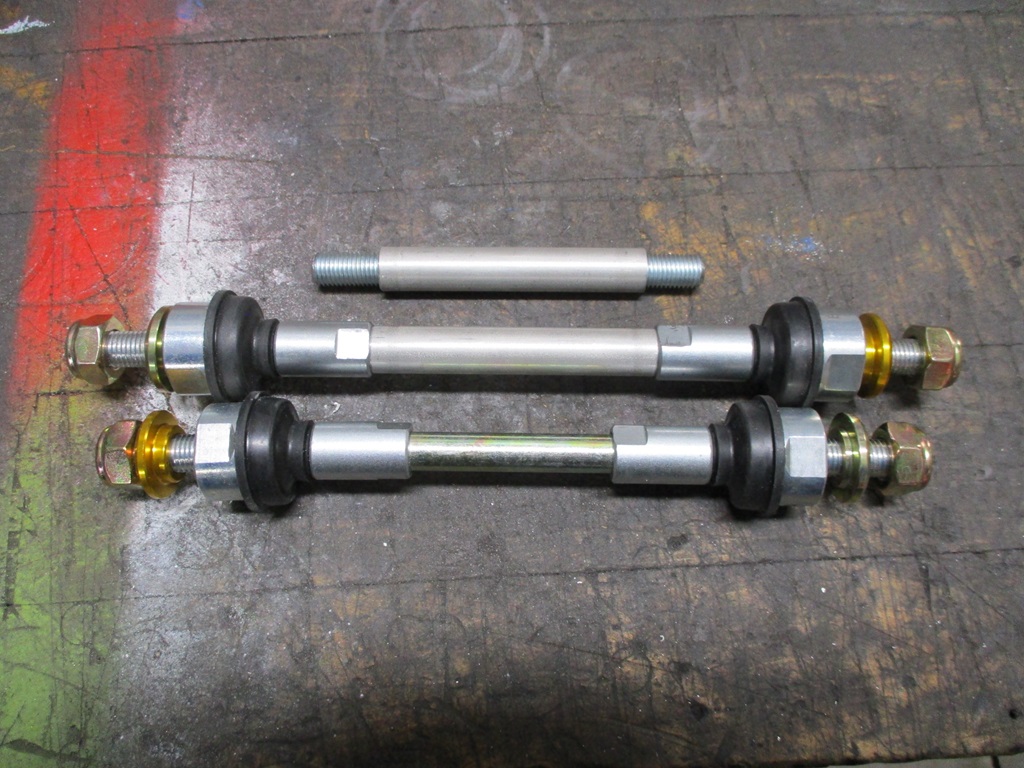
The zero-lash rod ends from the original swap are likely in a tote somewhere... The would have been too short anyway, so ordered the longest ones from Rodney. Once they arrived, they also were too short for the relocated sway bar, so took them apart and made them longer.
After Tuesday this week, the daily highs will be in the upper 40s and lower 50s for 2 weeks, so I would like to be done with the other side of the suspension by next weekend so I can take it for some more turning runs.
Last weekend I picked up 4 42x48 sheets of 1/8" steel to replenish my metal inventory. Then put the plasma cutter to work replenishing inventory of Lateral Link Relocation Brackets and the F40 Shifter Kit.
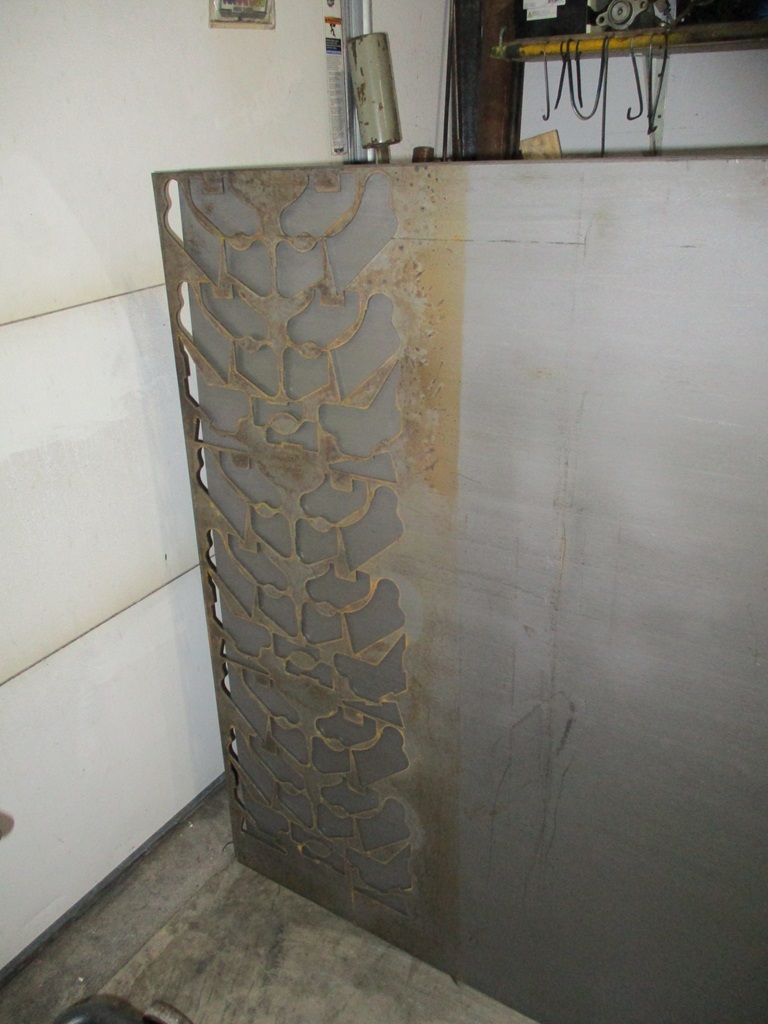
My youngest had some interest in the CNC plasma, so I walked them through the cad layout, sheet cam tool selection and g-code generation, then using Mach 3 to run the plasma table. Here is the end result. I am told it is some kind of video game.
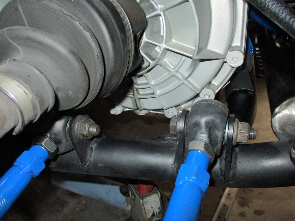
This weekend I was able to finish up installing the rod end lateral links and zero lash end links on the passenger side. From there it was time to align the car. 1/2" conduit with precise hole locations, 0.025" welding wire, some spare rotors to hold everything in place, then square the assembly to the wheel centers, then align. Only worried about rear toe and thrust angle this time.
Then I took the car out for a spin. My left ankle is about 80% and I am still wearing the brace, but didn't have any issues driving the car! Only put about 20 miles on it then put it back in the garage.
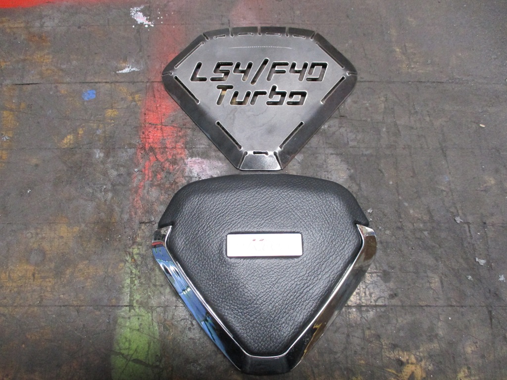
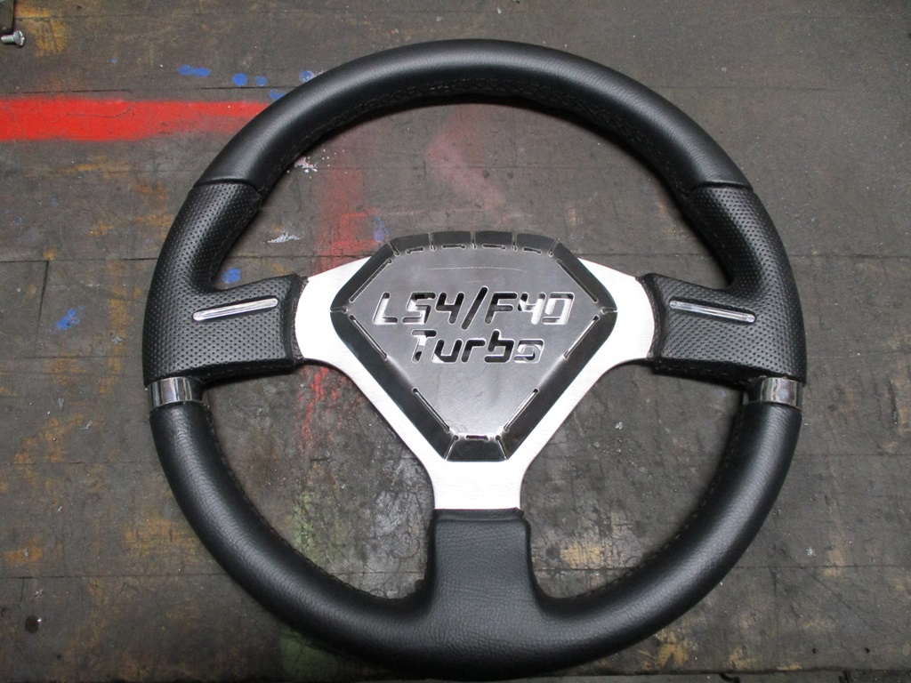
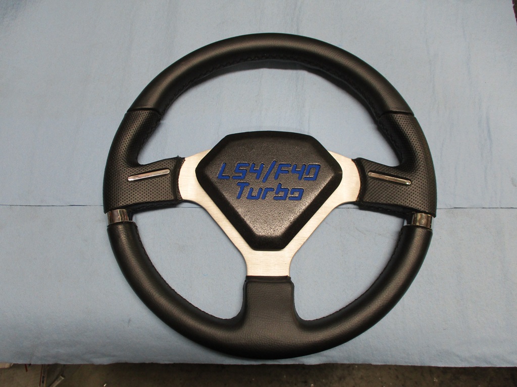
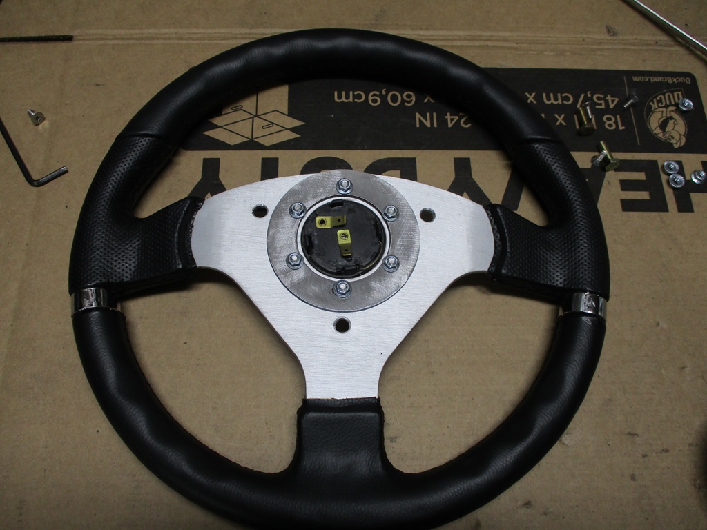
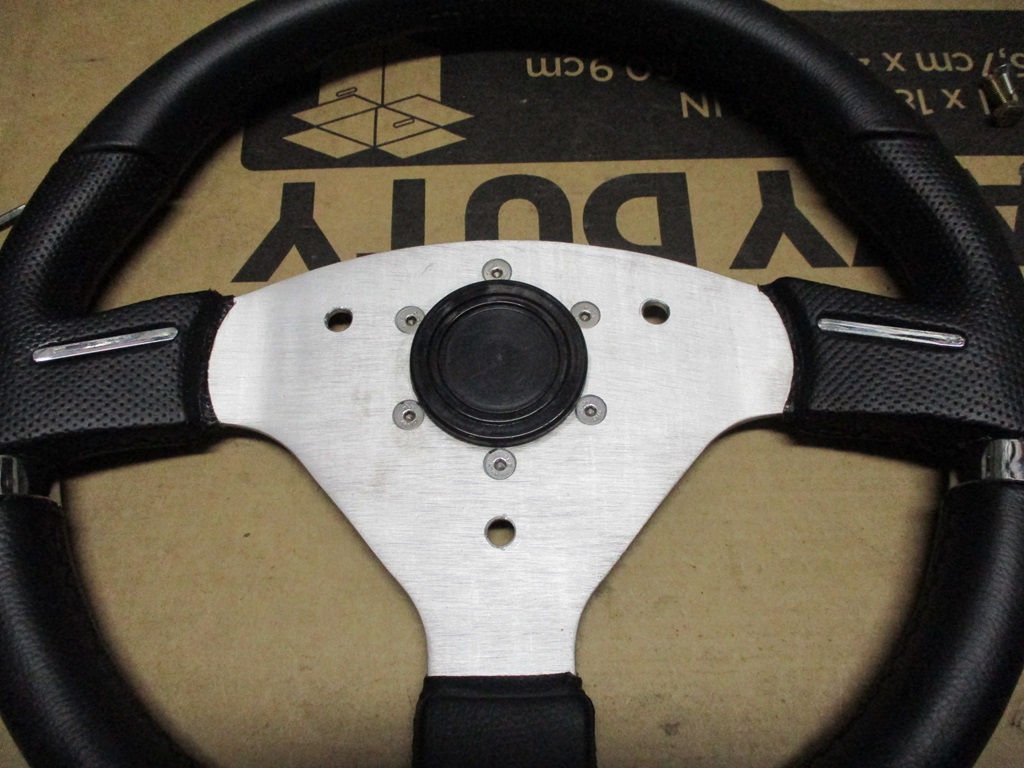
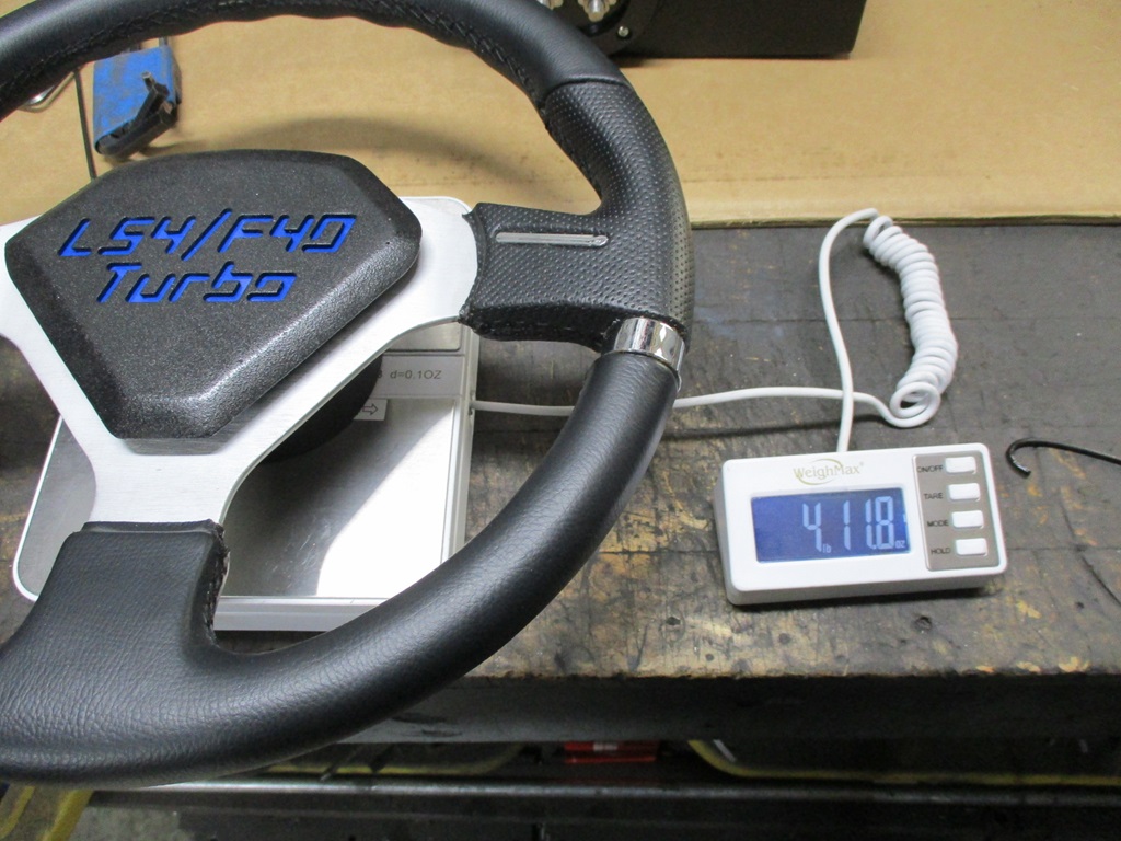
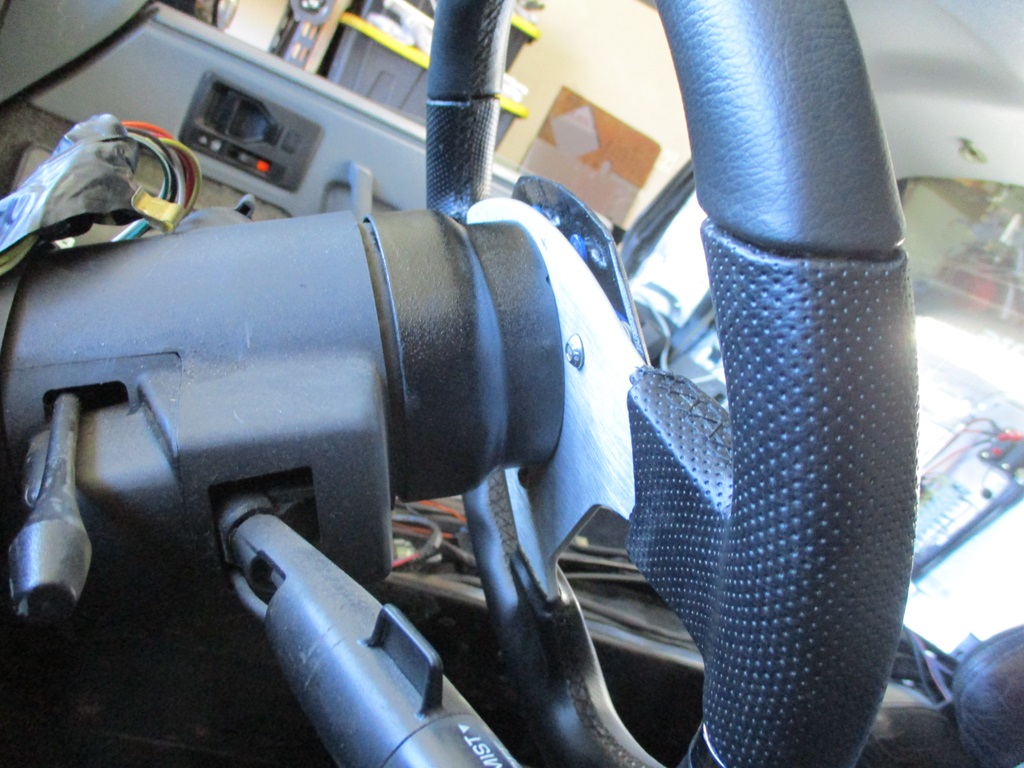
Back to working on the interior... I picked up a new steering wheel, but will have to modify it. I also wasn't feeling the center portion of the wheel and wanted something more custom. Here is the start too the new steering wheel center: Still need to weld up all the slots, smooth everything back down and then work on the insert.
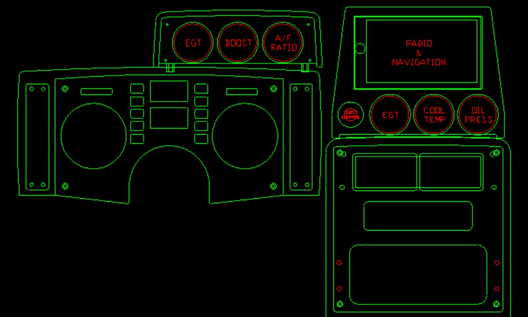
The current thought for all the gauges and 2din nav unit. Factory aux gauge housing with 3 gauges mounted over the instrument cluster and about 6-10" forward from the face of the instrument cluster. Then a custom housing where the aux gauges were to house 3 gauges, the manual boost control knob, and the 2DIN radio/nav unit.
[This message has been edited by fieroguru (edited 02-04-2024).]
Nice, and if I asked this before I apologize, did you find gauges small enough to fit in the GT gauge pod? I see you're making a customer fascia for it which is cool.
I have a transmission temp digital gauge that I took apart, and it will fit in the space and display 95% correctly through the stock fascia, just haven't figured out a way to mount it in there yet. So if there is a brand/series you can recommend and share how you'll mount the gauges in there, it would be appreciated it.
Vince, I cut out the prototype this evening. Just some slight modifications and it will be ready for install.
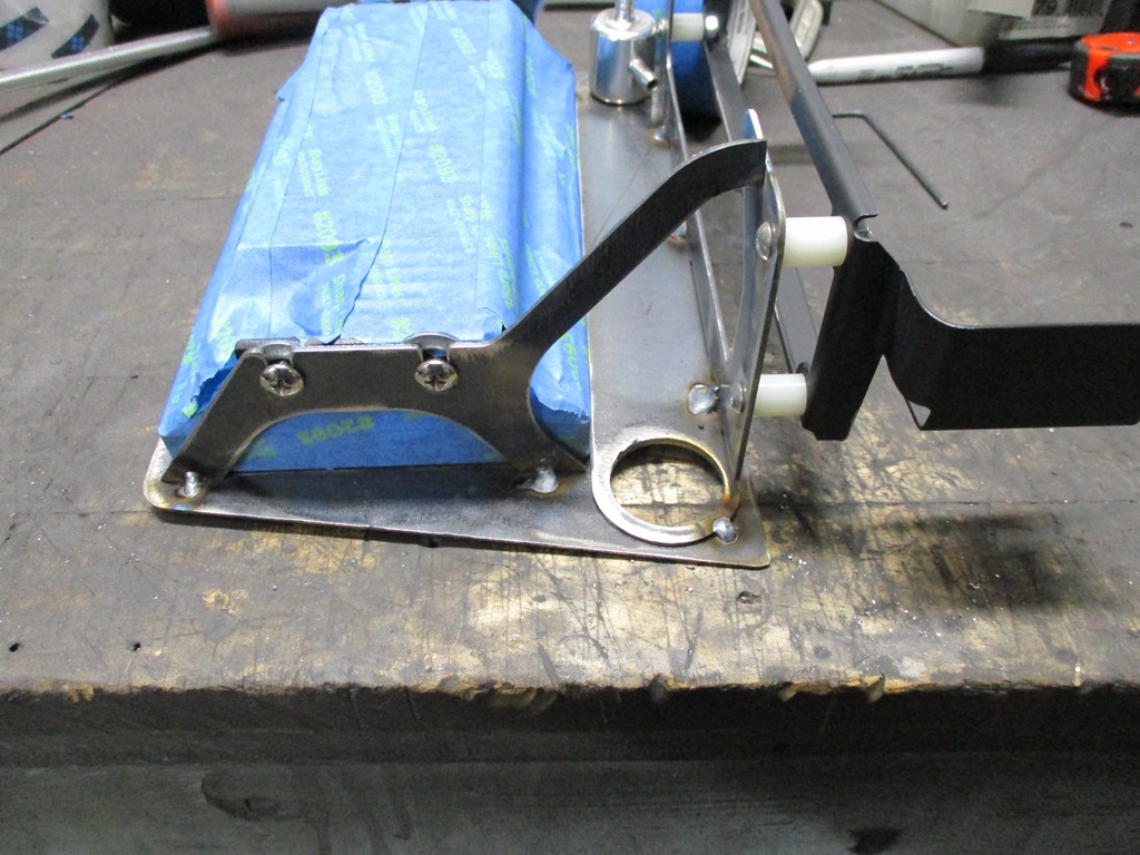
Most of my aftermarket gauges are the glowshift brand. They seem to barely fit, but fit they do. Most of these 2 1/16" gauges have a U bracket that bolts to the back of the gauge to hold it tight against the plate. I plan to install all the gauges on the plate, then install the plate in the housing. I will trim these U brackets down as they don't need to be as long as shown.
Thank you for the pics and info. I admit I am feeling a little dense here. I can clearly see the u-bracket on the gauge, with the 'arms' moving to the face plate you made. But I don't understand what's affixing the bracket to the faceplate?
At first I thought maybe the bolt system would expand to act like a tension rod to hold the bracket between the back of the housing and the face, but then it's putting all that pressure outward on the face, which is being held on by the factory screws in the factory plastic threaded holes. I would imagine you wouldn't want to do that, out of concern of the plastic cracking. So I'm stumped.
Vince, All 3 gauges will be clamped to the face plate with the U-brackets. The face plate is attached to the housing with the 4 screws in the corners of the face plate. The housing will be mounted to another bracket using the 4 bottom screw holes.
I am planning to have the gauges installed above the instrument cluster this weekend, so I can post some better pictures.
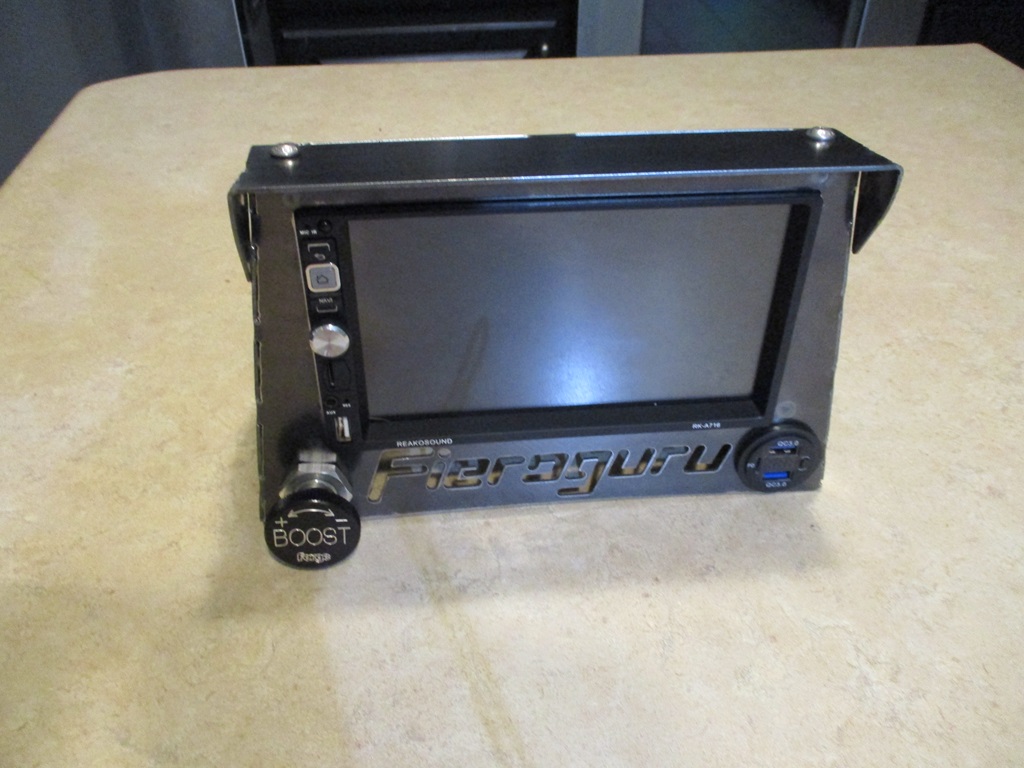
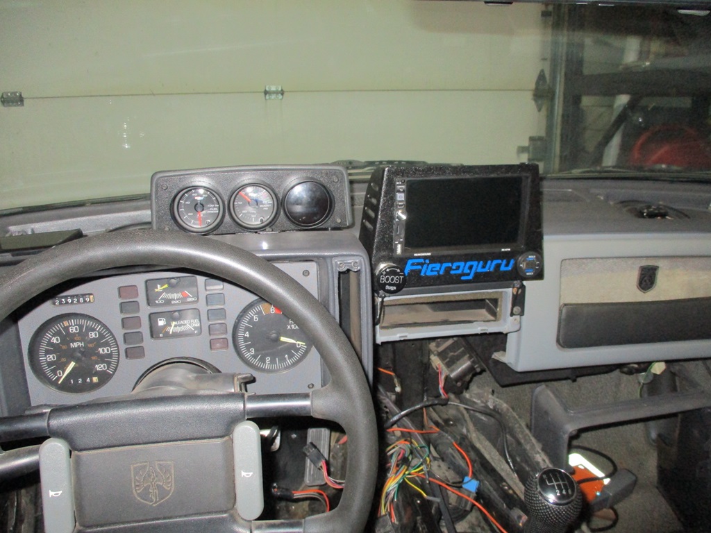
The GPS/NAV unit above the 2 1/16" gauges was too tall once it was mocked up... so it needed some reworking.
This is what I came up with:
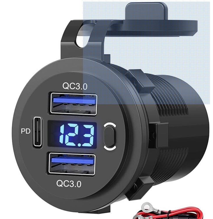
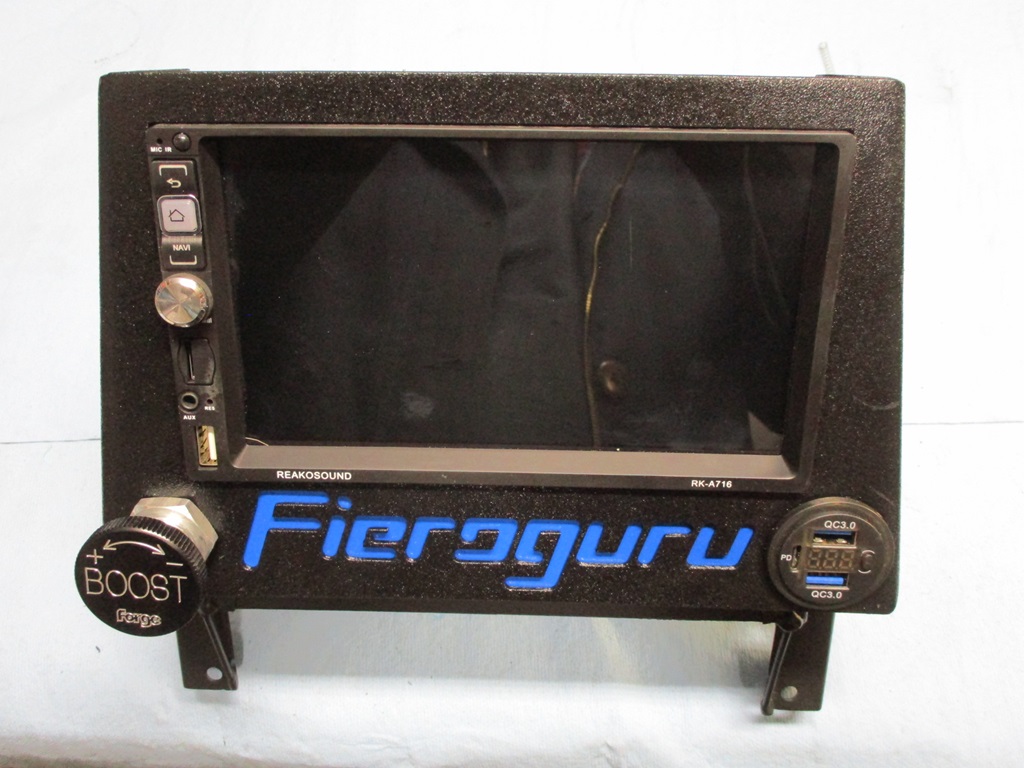
It kinda looks like an Etch A Sketch! It reuses the stock aux gauge bracket so it is a bolt in modification. The boost adjuster is on the lower left and on the lower right will be a 3 port USB charger with digital voltage display.
With this mock up, I was able to update the drawings so the next version should be the final one.
[This message has been edited by fieroguru (edited 02-11-2024).]
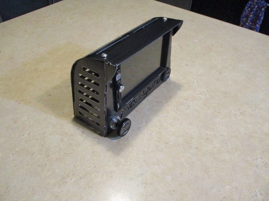
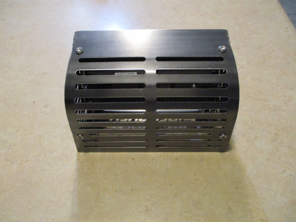
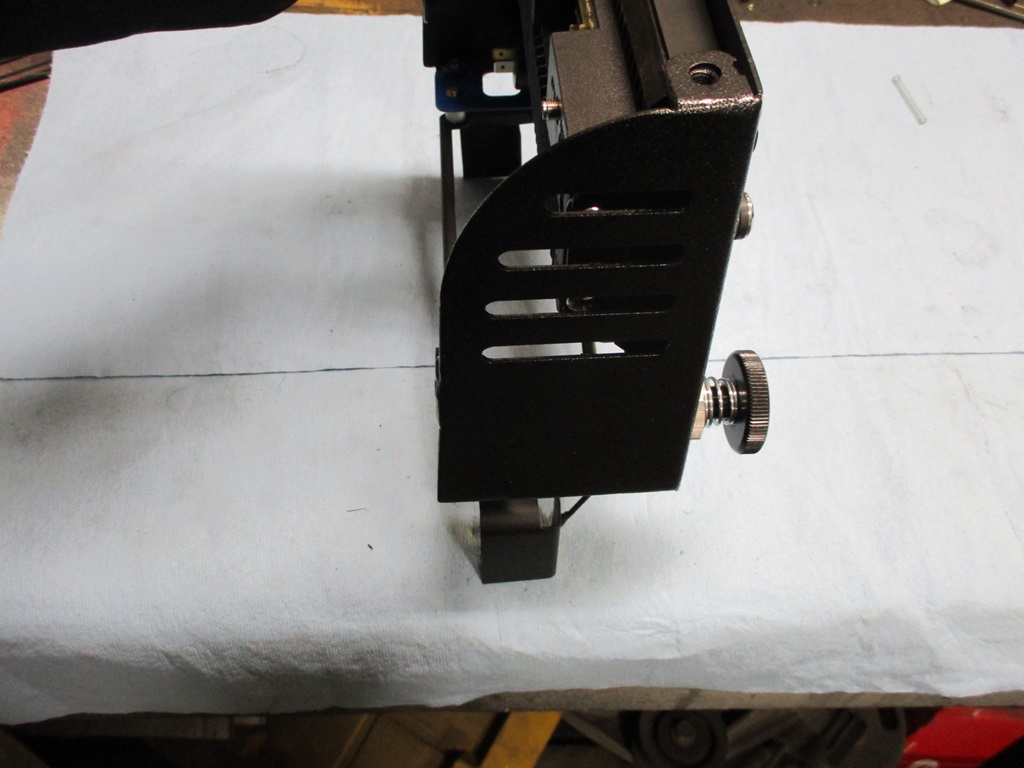
Playing around with options to enclose the radio...
The slots are for ventilation, lightness, and to access the 4 bolts holding the radio in place. The back panel/front sun visor bolts on and I need to dial in the shape of it a little more. Not really loving all the slots, but they are a start until I think of something more creative.
The steering wheel is getting closer. The center pod is finished. It is spring loaded and activates the horn puck that came with the wheel. Now I need to fabricate the adapter to allow it to mount to the Fiero column.
The new center piece reuses the same 3 bolts as the original center.
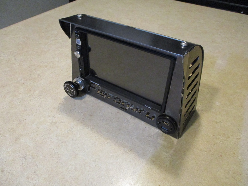
The radio/NAV face, sides and base are complete. Still need to finish the top/back panel. Thinking it will be aluminum.
I ended up removing the lower slots on the side and just kept the top 4 (2 are to access the bolts holding the radio in place).
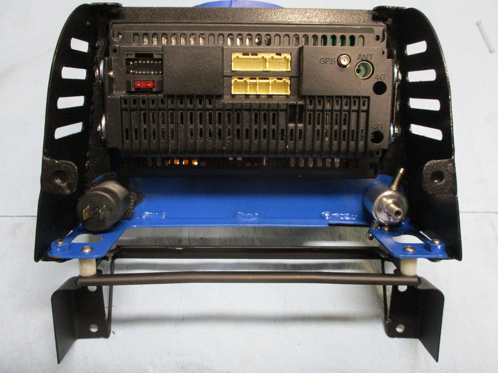
Here is the business side:
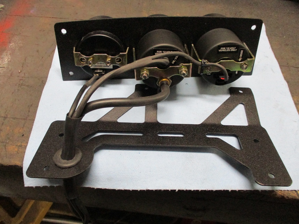
Also started looming up the 3 gauges - A/F ratio, Boost, and Fuel Pressure:
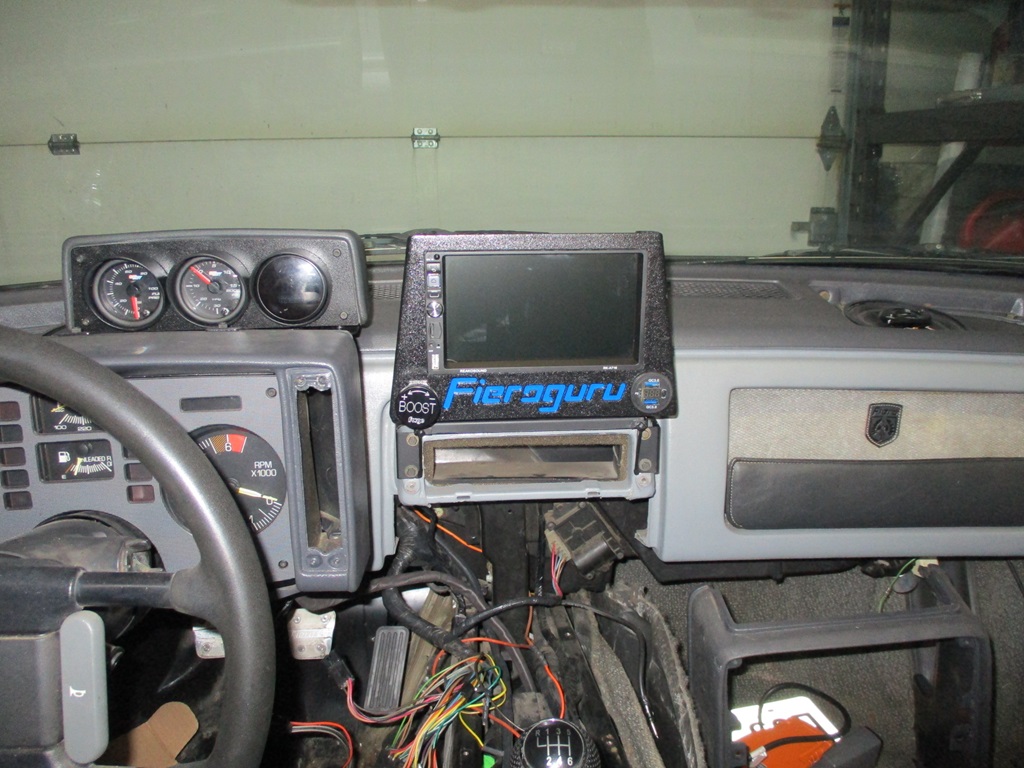
Gauge pod ready to be installed:
Gauges and Radio/NAV unit installed:
Now I can pull the dash and install the front speakers, the amp and wire up the radio...
You are indeed capable. All I want to do is wire my car for a TPI coil on plug like you did for Trinten and am entirely intimidated. On my behalf though I haven't seriously tried to actually figure it out. It appears daunting. Perhaps at one time it was for you also. Excellent work.
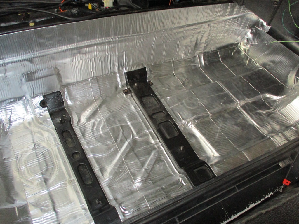
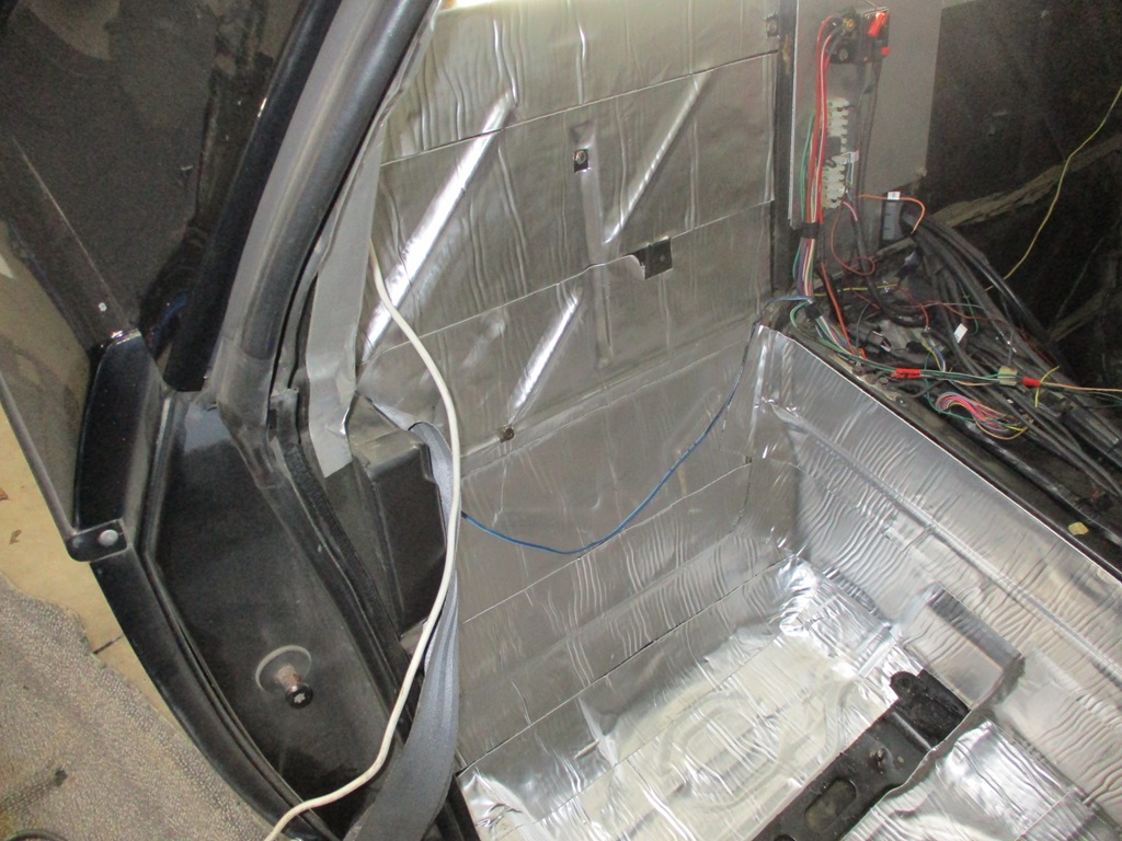
Currently have all the interior back out adding sound deadening. Passenger side is done:
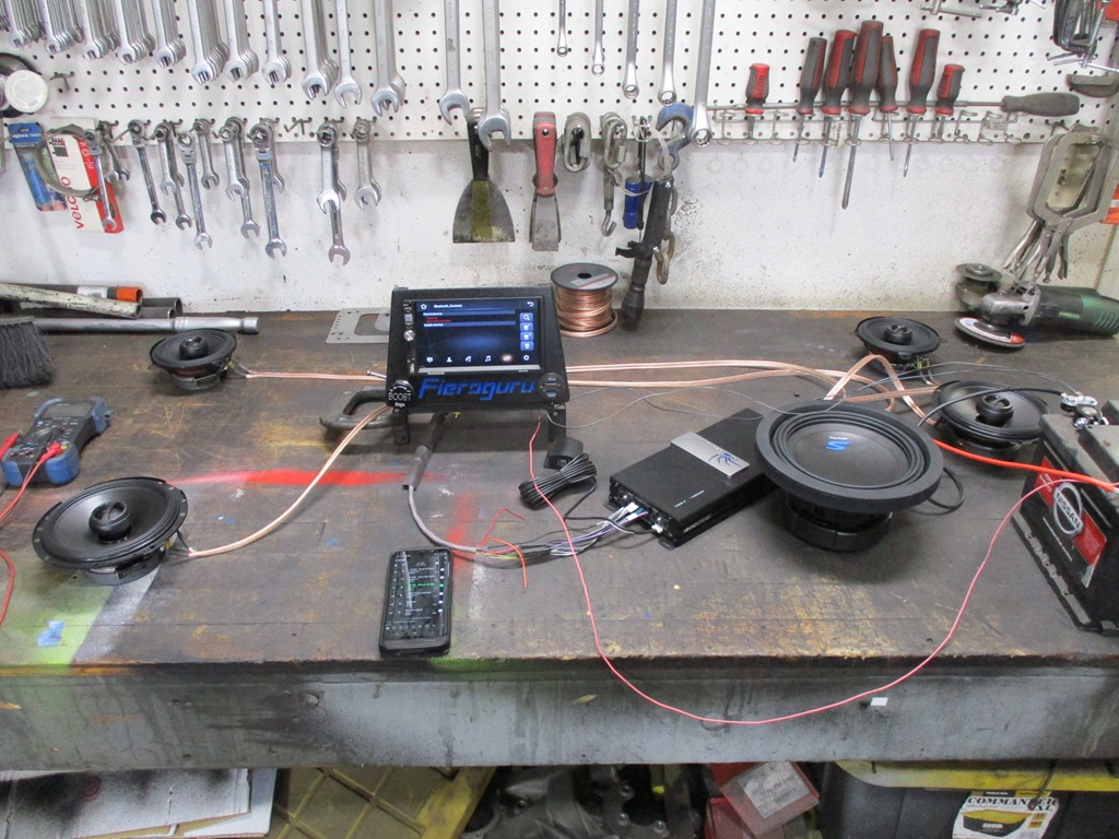
Also wired up the stereo amp and all the alpine speakers up on the bench to test them out.
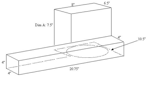
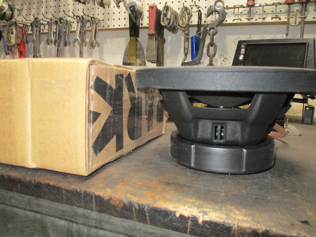
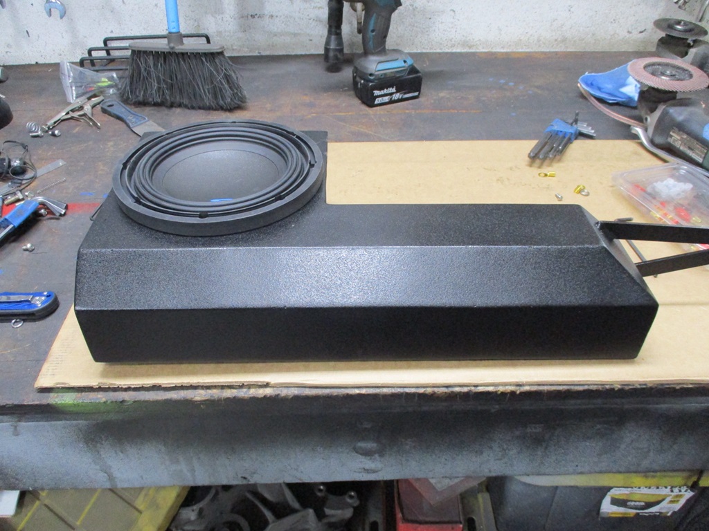
Also started measuring and drawing the sub box. Ideal size for this 8" sub is 0.30 cubic ft sealed box. I plan to make it out of 16ga steel on the plasma in 2 parts, then weld it up. Easily have room for it under the dash. It is amazing how much more interior volume you get with 16ga vs.1/2" MDF.
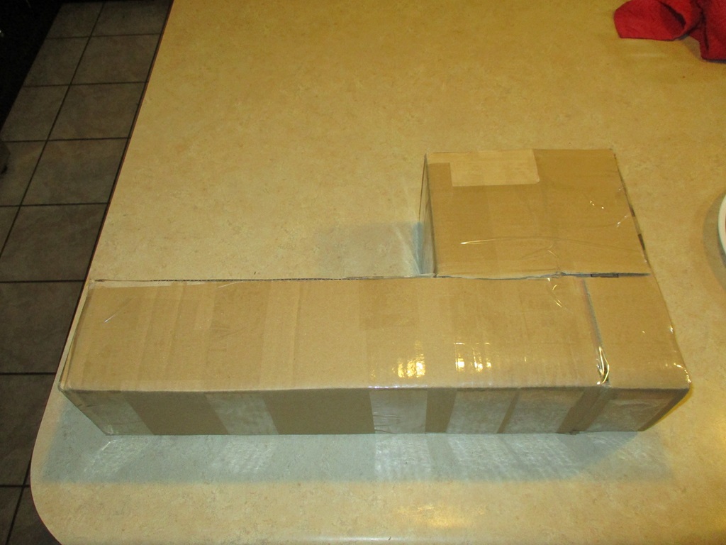
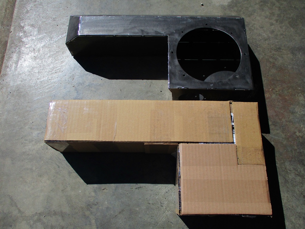
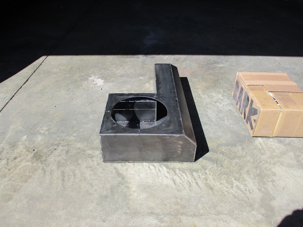
Played with some cardboard to mockup the box. This box is very similar to Alex4mula's, except it is 4.5" tall, the front tube is 4.5" deep, and the overall length/width is 20.75 x 10.5". I plan to make this out of 16ga steel vs. 1/2" MDF. Partly because the CNC plasma makes cutting these types of things easy and partially because it allows more air space in a smaller package. With the relatively small span I don't expect the box will flex much.
As for the weight, a 4x8 sheet of 1/2" MDF is 66 lbs and a 4x8 sheet of 16ga steel is 81.7 lbs. so it would be easy to say the use of 16ga vs. 1/2" MDF will have the box weigh about 24% more. However, with the dimensions of Alex4mulas box remaining the same, the 1/2" MDF has 0.248 ft^3 and using 16ga is 0.376 ft ^3 or about 53% more interior volume. So, when you build a box to a specific volume, the steel one can be smaller, use less material, and overall be lighter.
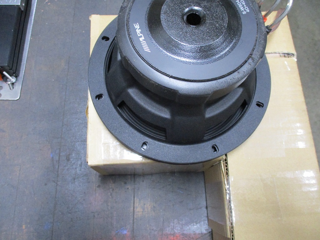
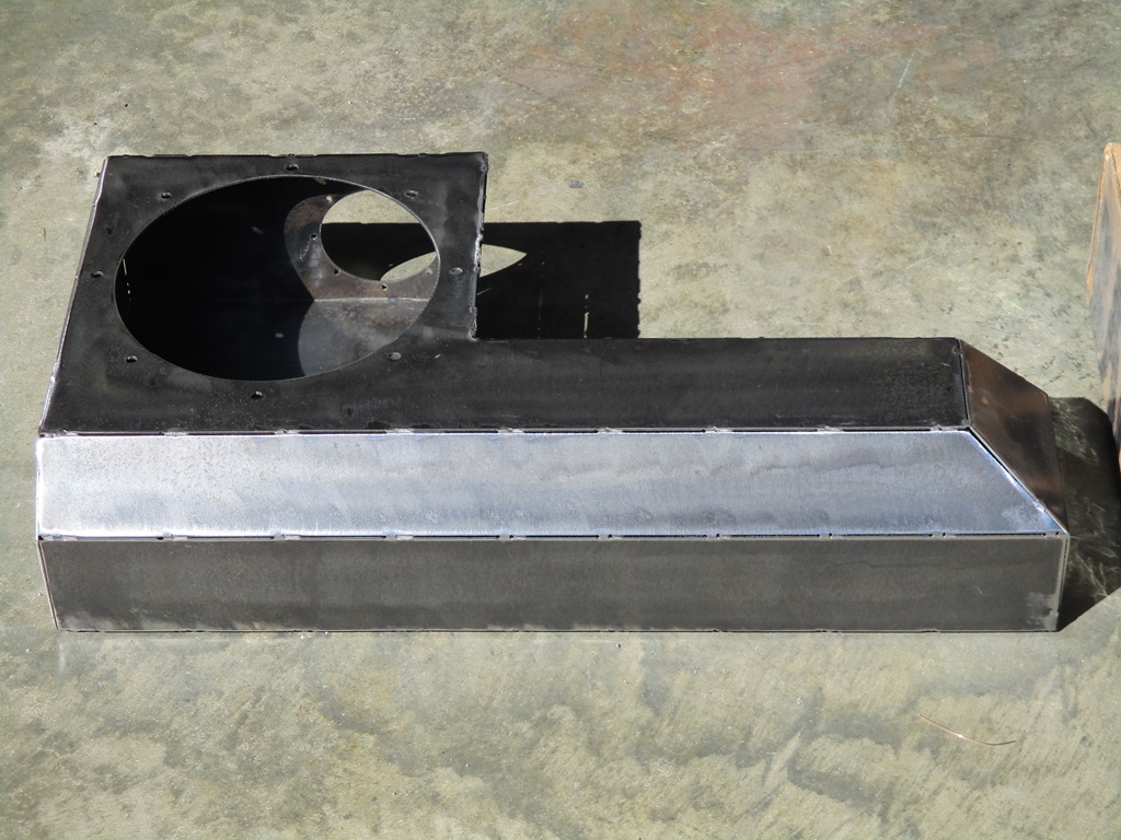
The 4.5" thickness easily clears the speaker magnet and subwoofer depth:
The 8" width portion has the sub flange hanging off the sides slightly, and from the mockup this could be wider as there is room on both sides - especially at the elevation of the sub flange.
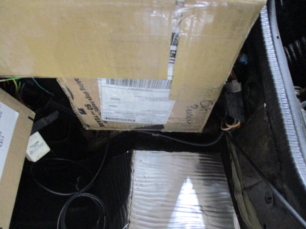
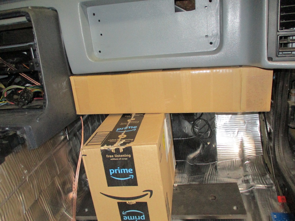
This is looking up from the floor to the box and the side where the sub would be mounted and there is a gap on both sides.
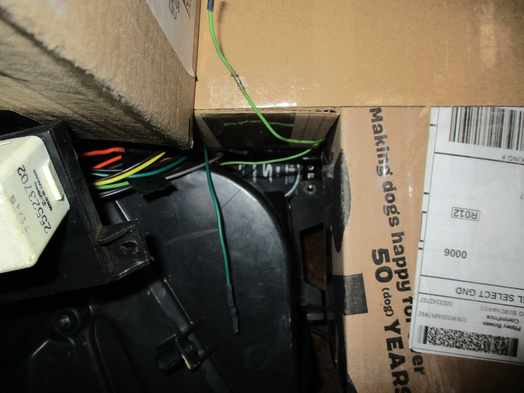
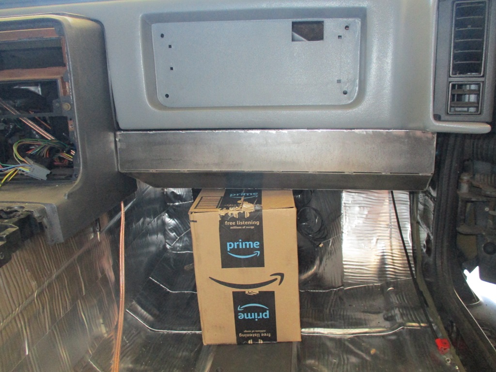
Here is the current clearance to the heater core. By removing the bracket, the box could be a little wider in the back:
Here is a pic of the box installed from the front:
The recommended sealed volume for my sub is 0.30 ft^3 and this mock up box is 0.345 ft^3 so I need to make it a little smaller. Current plan is to reduce the overall height by 1/4", reduce the front tube depth by 1/4", adding a 1 1/2" x 1 1/2" 45 degree taper at the lower corner of the front tube, and probably something along the outside edge as well.
The flat pattern is too large to cut as a single piece on the cnc plasma, but I can easily cut it in 2 pieces.
[This message has been edited by fieroguru (edited 02-26-2024).]
I have some concerns about the panels of the box having resonances (high Q resonance due to the steel material) in the low audio-frequency / subwoofer range being excited and resulting in the panels buzzing, but I guess you'll find that out; maybe internal panels can be used to tie opposing faces together, or dynamat or similar.
Are you able to perform a modal analysis on the box?
If you're interested, I could run a modal analysis on SolidWorks, using your dimensioned drawing to define the part.
I will know how it performs this weekend as I continue my testing on the bench and playing around with the oscilloscope . The panel at the top of the box directly above the sub will be the one to resonate if there is any as it has the longest span. If needed, that panel has lots of room for a support rib on the top side.
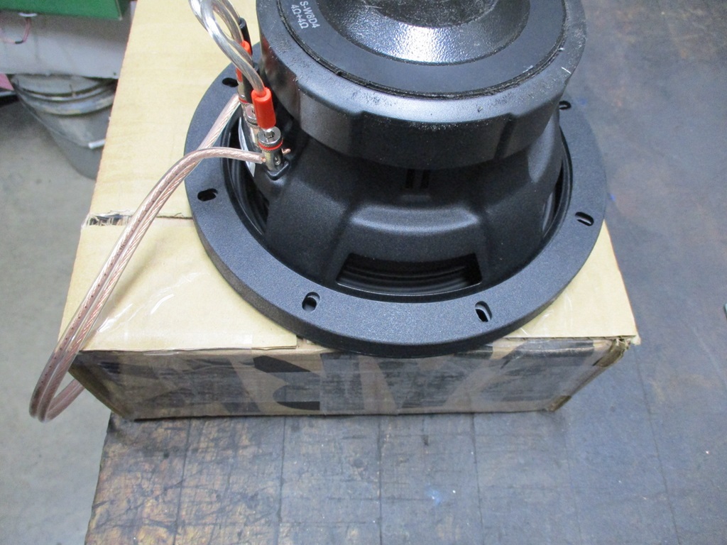
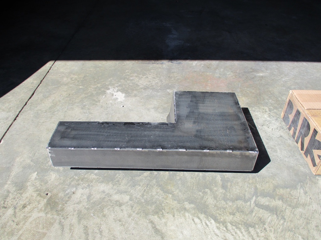
Then I taped up all the seams and the connector hole, installed the sub and did some testing. Sounded better than just the sub sitting on bench. No noticeable resonance or other tone changes when I touch different sections of the car.
Not shown in the pictures was the 2nd ring with nuts welded to it that welded on the inside of the box. This way I can bolt the sub in place with M6 bolts and not with just sheet metal screws.
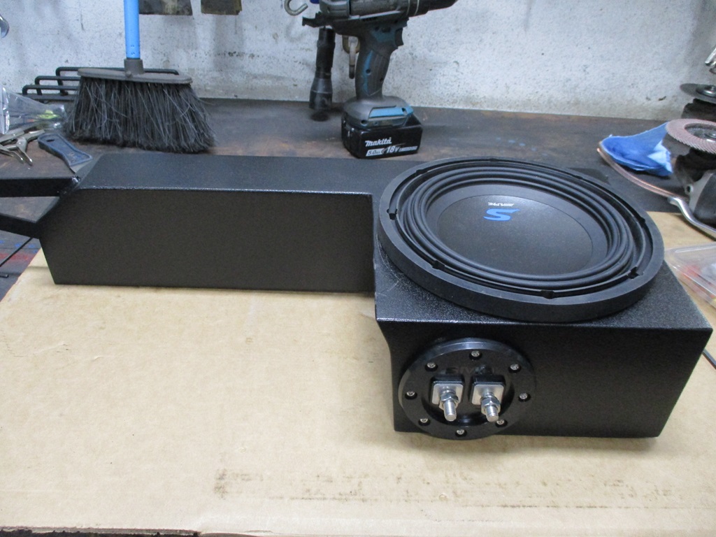
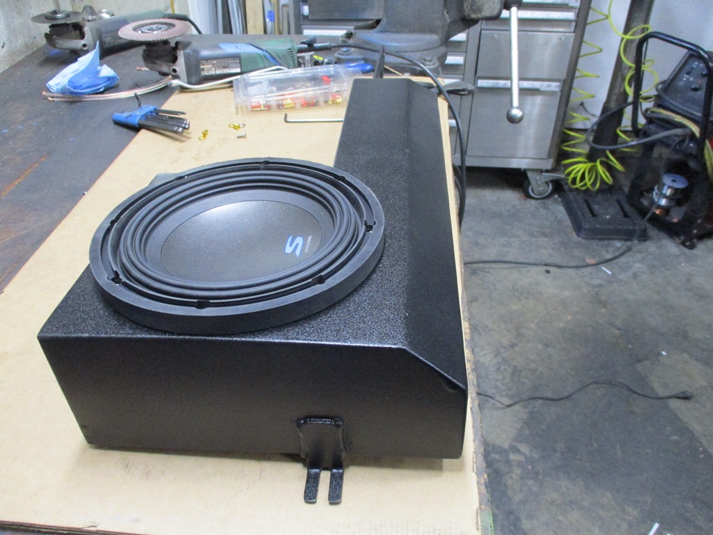
I now have about 95% of the sub box welded up (ran out of welding gas) and have started smoothing the welds. I think I have some flux core wire I can use to finish off the welding... or I could tig it.
On Sunday I would like to get the welds smoothed and the mounting brackets attached. I might even get to the point of painting and texturing it.
[This message has been edited by fieroguru (edited 03-02-2024).]
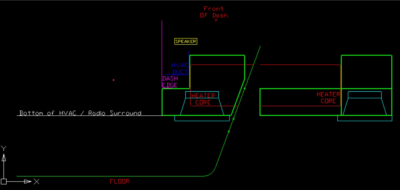
Originally posted by Will: From looking at this diagram, I didn't realize the box was just flat like that. Do you have something else in the volume used by the OE sub box? I had assumed, again based on the diagram, that you'd be using the OE sub box volume.
I could have made it taller, but that would just increase the volume beyond the sealed volume they recommend (0.30^ft), and make it heavier.
With the use of 16ga steel my flat box actually has more internal volume than Alex4mula's when made with 1/2" MDF.
I could have made it taller, but that would just increase the volume beyond the sealed volume they recommend (0.30^ft), and make it heavier.
With the use of 16ga steel my flat box actually has more internal volume than Alex4mula's when made with 1/2" MDF.
I was referring to using the vertical volume instead of the horizontal volume so the box would keep the target volume but not intrude into the footwell quite as much. So you've left the original sub box volume unutilized?
[This message has been edited by Will (edited 03-03-2024).]
When I measured out the space, originally I was trying to maximize the volume. The sub is 8", the flange is 8 3/4" diameter, and there is only 8" of clearance between the A/C Heater core housing and the dash bracket. So the sub has to be be some amount lower than the A/C Heater core housing. I could probably raise it about 1", but then the geometry of the box gets more complicated as the magnet would then be higher than the bottom edge of the dash, so in the end, I kept it a simple flat box that protrudes 1 1/2" lower than the A/C Heater core housing and the magnet has about 7/16" clearance to the inside of the box.
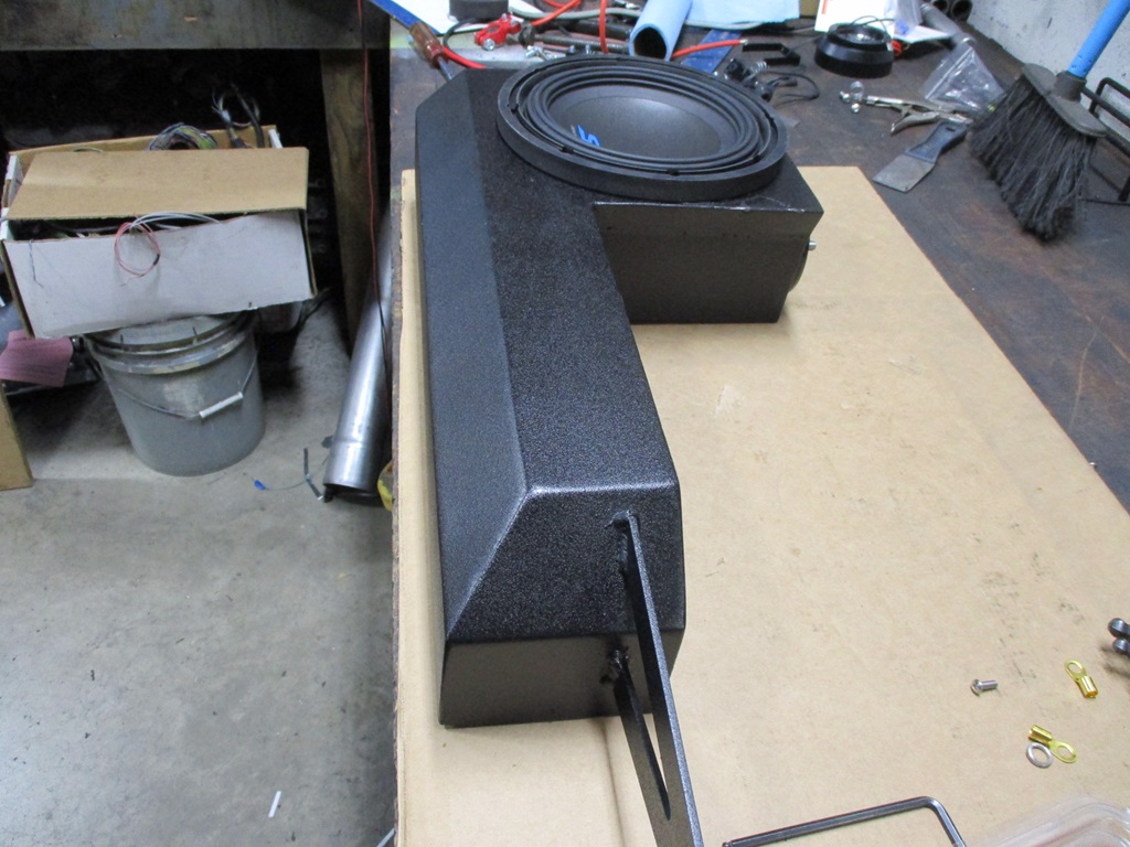
Smoothed all the welds on the sub box, then put it back in the car to start working on mounts for it. For the left side, I made a bracket that will bolt to the steering column support tube in the center console. It is far enough back to clear the console skeleton and surround.
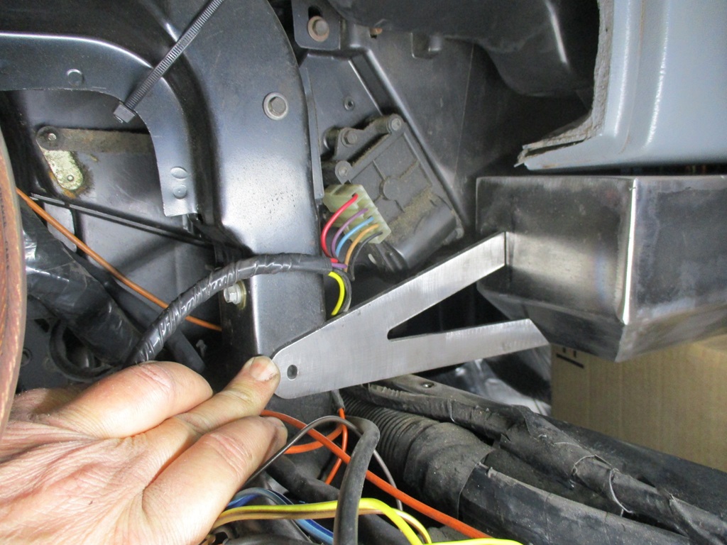
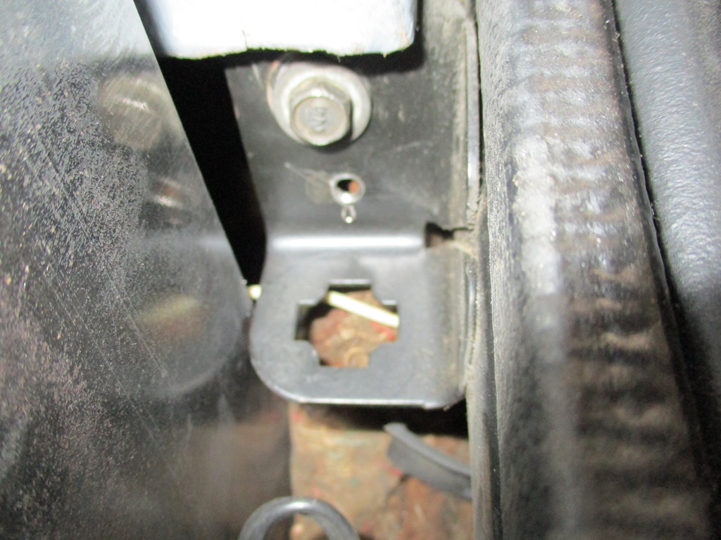
The bracket for the right side will just be a L bracket with a hole in it to pick up this bolt:
Put the welding gas bottle in the back of the truck so I can get it filled on Monday.
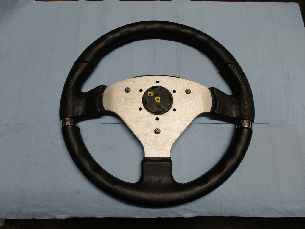
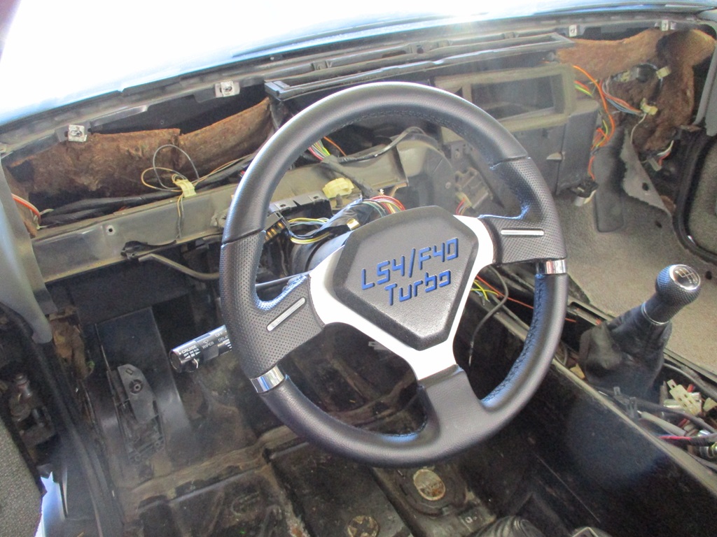
Then i went back to the steering wheel and the brackets needed for attachment.
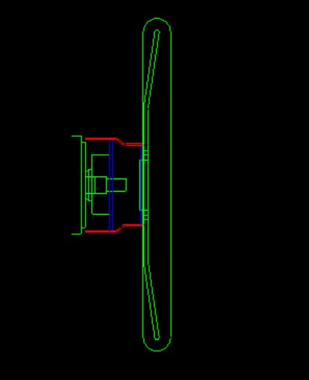
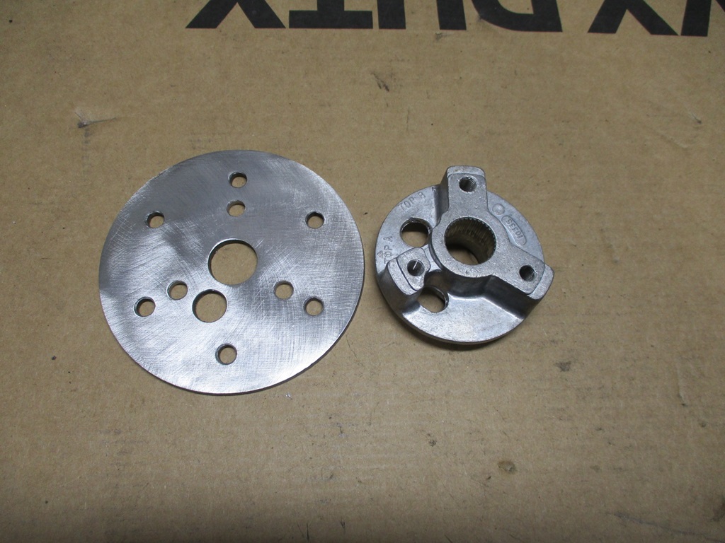
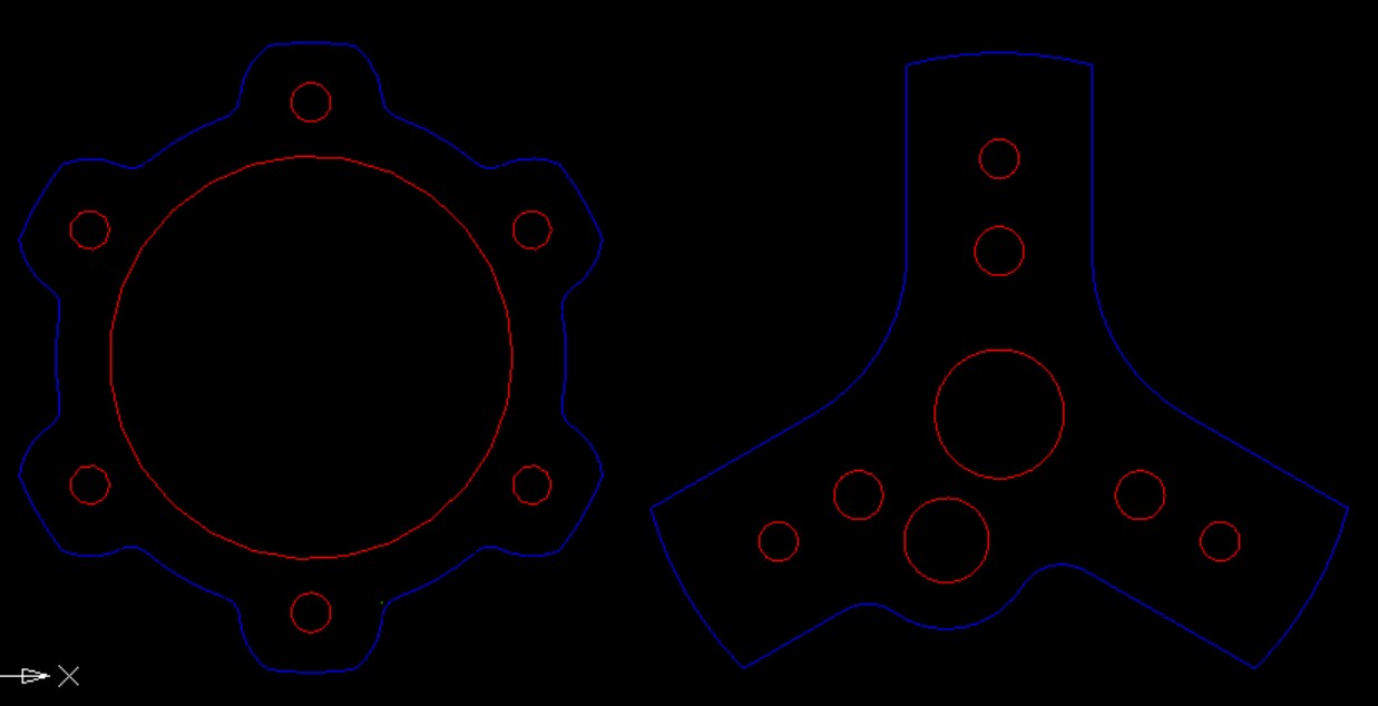
Here is a general mock up drawing showing the aluminum splined flange, two blue adapter plates and the red part is an exhaust reducer. The plates and the exhaust reducer will be welded together to make the steering wheel adapter mount.
Here are some of the older plates before the design was further refined:
This is what the final design of the two adapter plates will look like:
Grant makes the wheel adapter that bolts to that hub.
Does that wheel have a weird bolt pattern?
The wheel is a 6 x 70mm pattern. Most of the off-the-shelf adapters are about 1.6" deep and I need one that is just over 2" thick so the column nut clears the horn button puck on the wheel.
Another productive weekend doing small fiddly stuff, but it needed done.
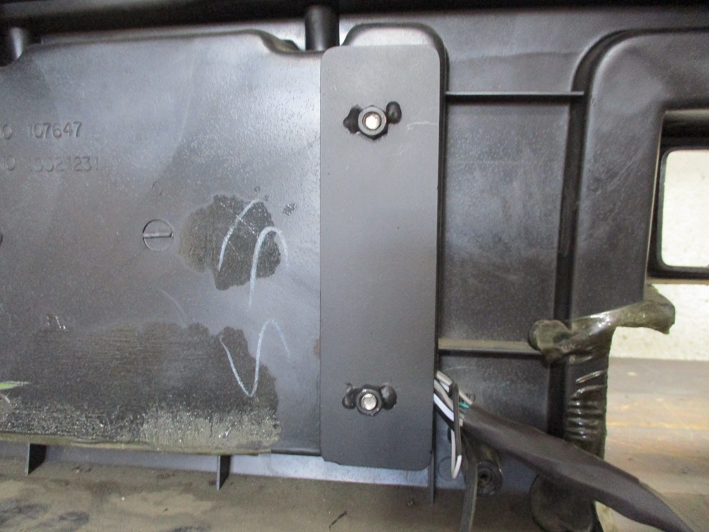
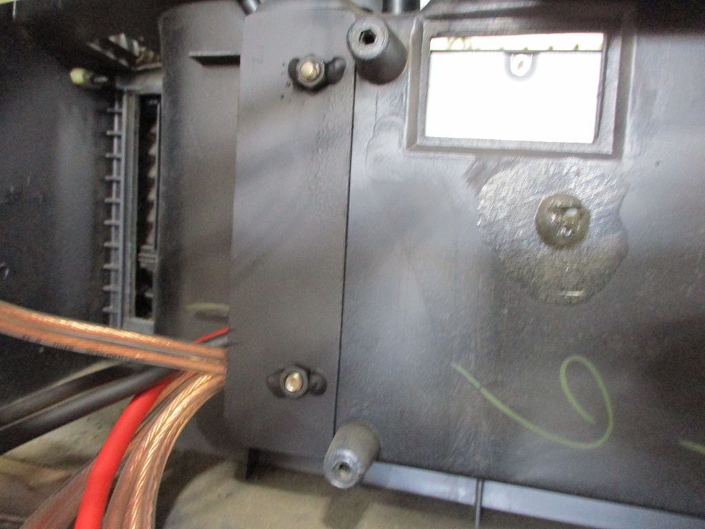
Mounted and wired the amp. The initial plan was to have to wires go through the wall of the pocket, but they would not clear the HVAC tube, so I made a wiring access hole in the bottom of each corner. The amp weighs 5 lbs, so I added support plates for the 4 bolt holes that secure it.
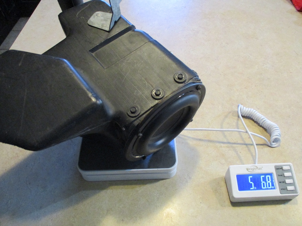
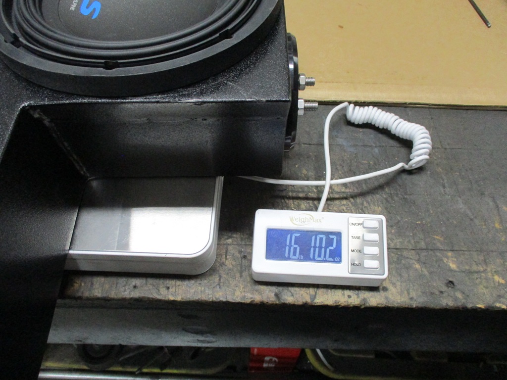
The sub box is also done. It weights 16 lbs 10oz and the stock sub housing with the the larger woofer is 5lbs 7 oz, so 11 lbs more for the sub and 5 for the amp, so all the stereo mods will be in the 20 to 25 lb range, which i am OK with.
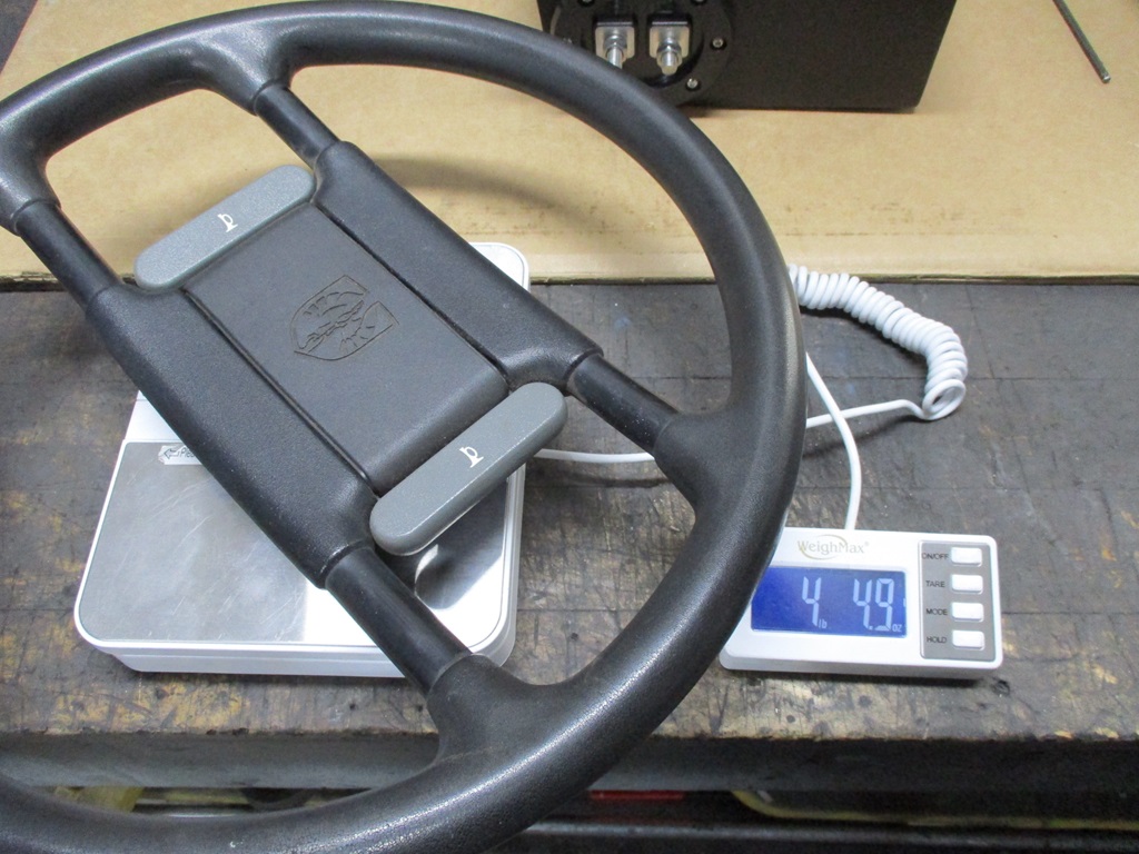
The steering wheel adapter is now done as well. It isn't fully tight yet, so the gap between the adapter and the column will be a little less. All the steering wheel custom-ness weighs 1/2 lb more than the stock steering wheel.