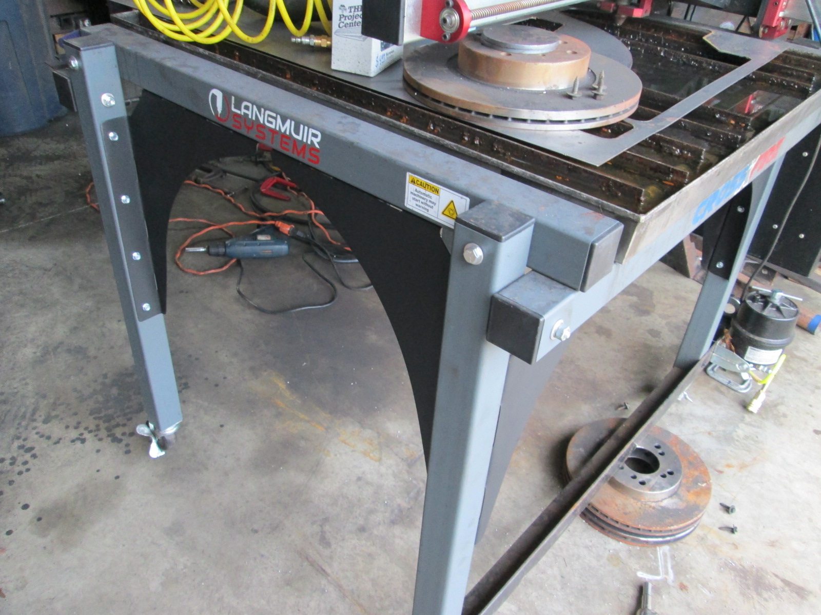
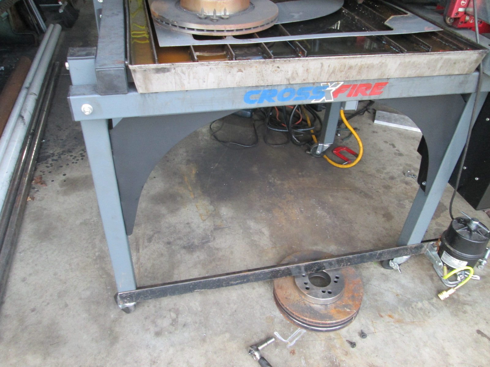
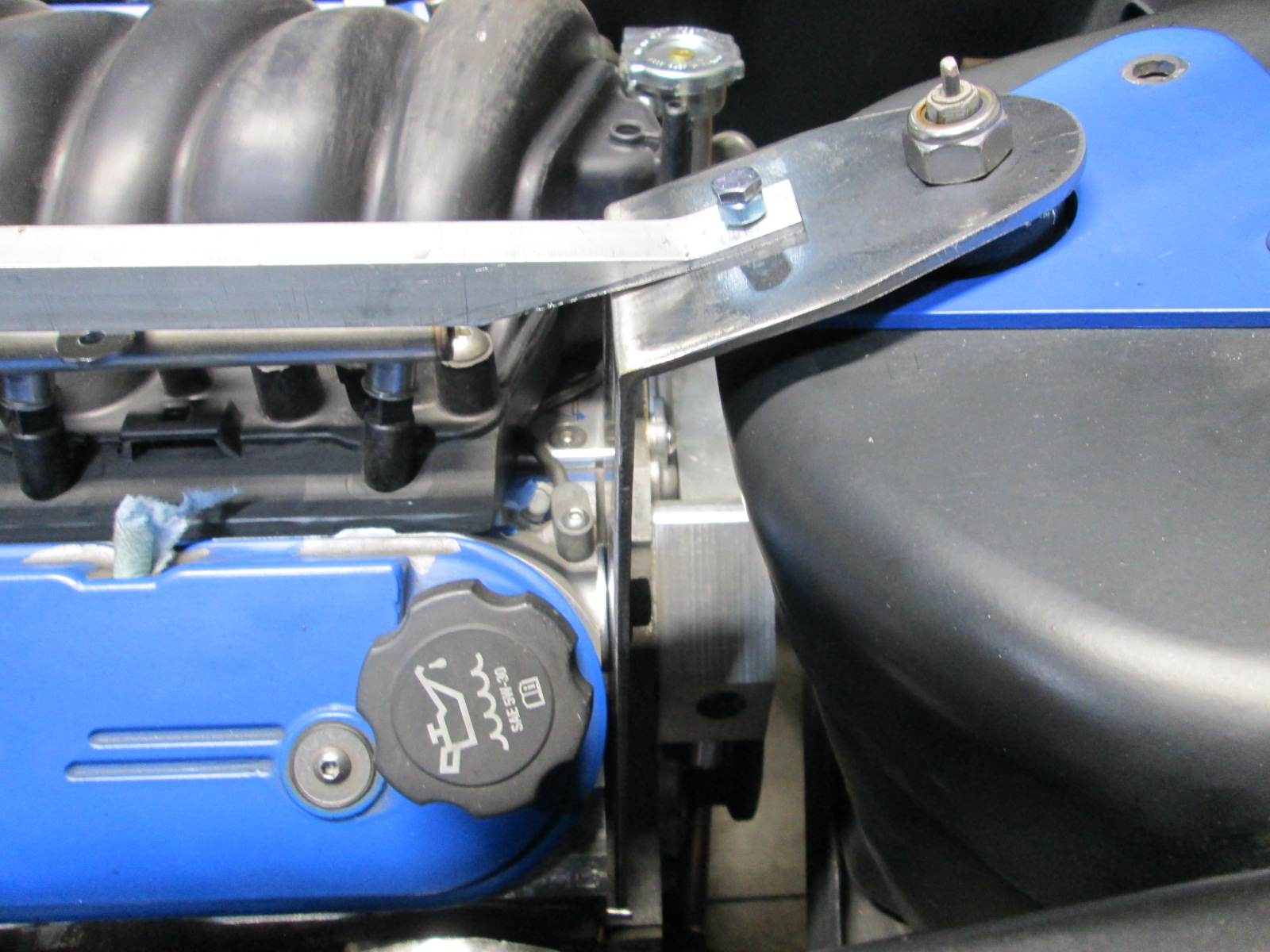
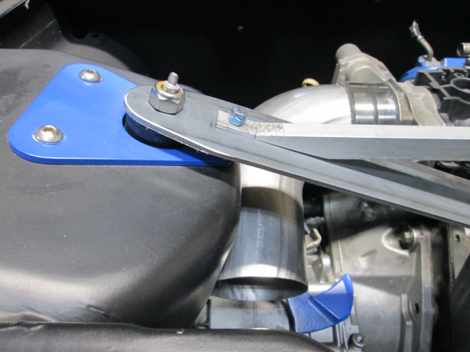
Here are a couple of finished pictures of the leg braces. I did order some leveling pad as well as some threaded couplers. I will weld the couplers to the cross brace and use the leveling pads to help keep the water table as close to level as possible.
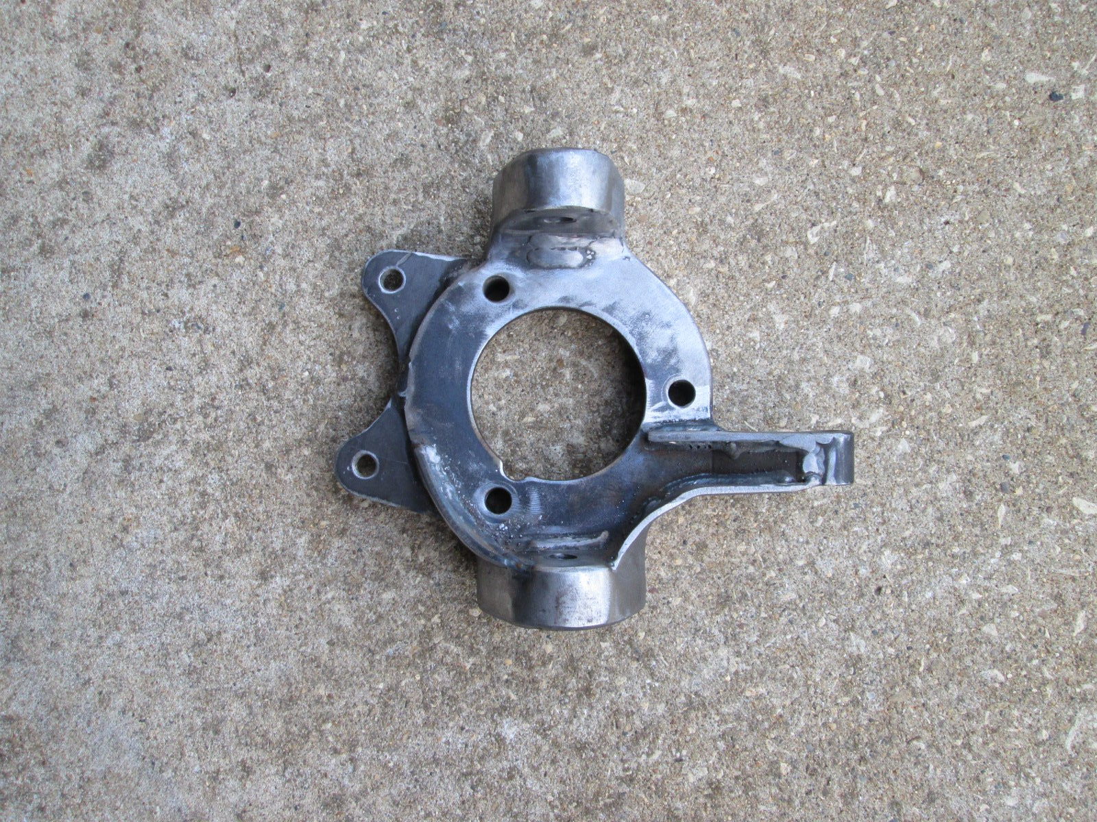
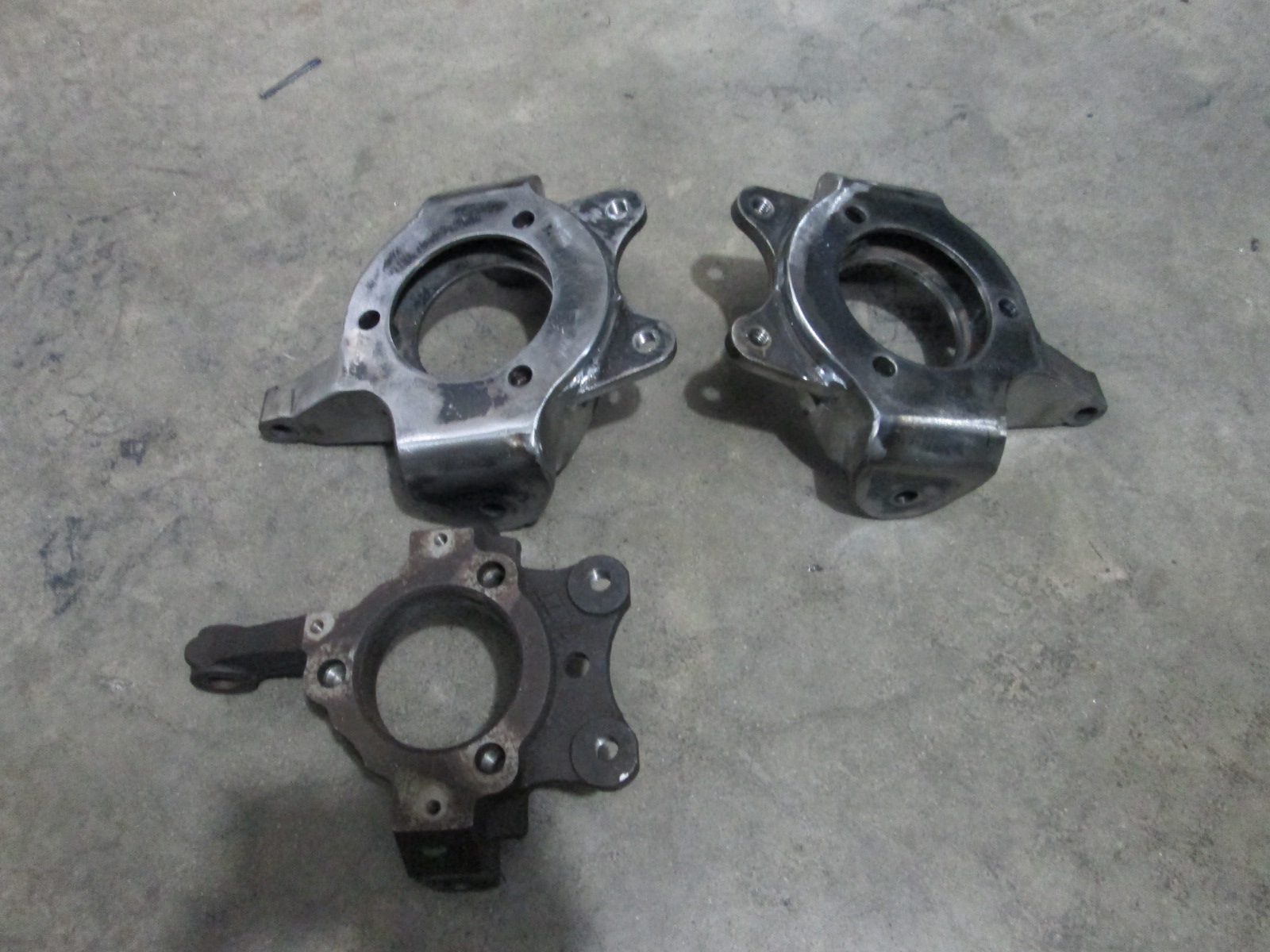
This is what the complete knuckle looks like. It weighs 6 lbs 7.3 oz, which makes is 1 lb 5 ox heavier than stock.
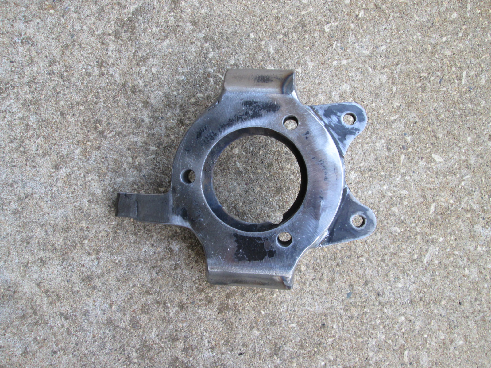
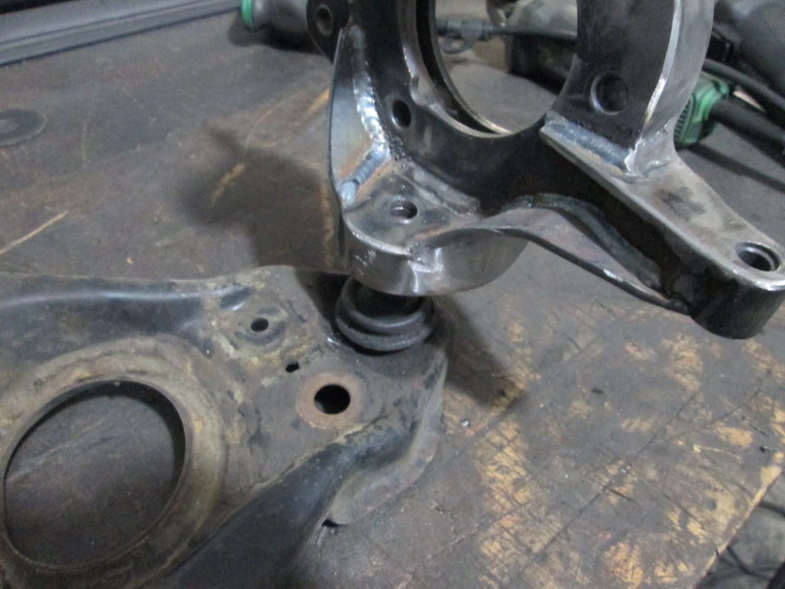
Here I just set it on the ball joint stud - I still need to clamp it in the mill and taper the hole.
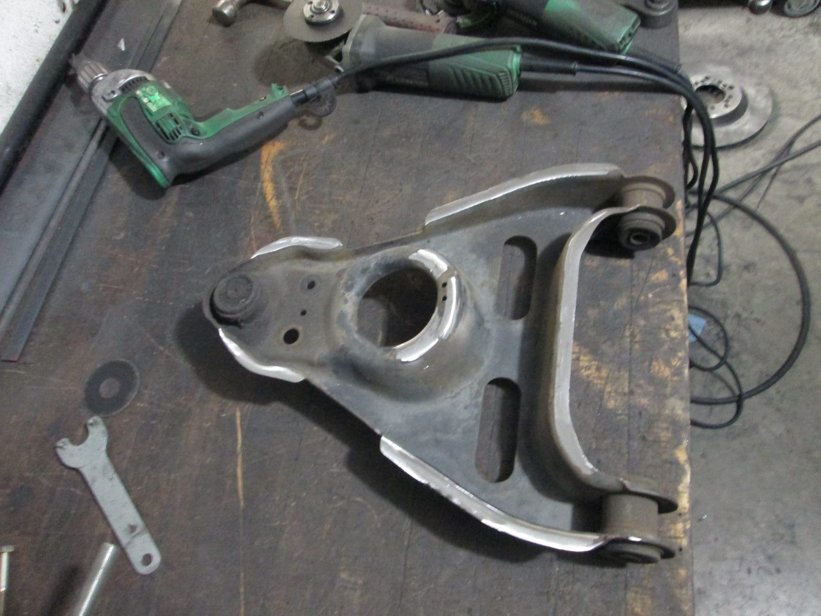
I went ahead and cut off all the welds holding the bottom half of the lower a-arm to the upper half.
Here I just set it on the ball joint stud - I still need to clamp it in the mill and taper the hole.
An additional gusset from the lower ball joint boss up to the inner end of the upper steering arm plate would be good. The way you have it, there's not a direct load path from this side of the LBJ boss up to the bearing mount hole.
[This message has been edited by Will (edited 10-03-2021).]
Originally posted by Will: An additional gusset from the lower ball joint boss up to the inner end of the upper steering arm plate would be good. The way you have it, there's not a direct load path from this side of the LBJ boss up to the bearing mount hole.
Looks like any additional gussets will be hard to add without compromising wrench clearance and room to insert and bend the cotter pin.
An additional gusset from the lower ball joint boss up to the inner end of the upper steering arm plate would be good. The way you have it, there's not a direct load path from this side of the LBJ boss up to the bearing mount hole.
if he did that, he may as well "box" in the side too.
Looks like any additional gussets will be hard to add without compromising wrench clearance and room to insert and bend the cotter pin.
I'm thinking of piggy-backing the gusset on the lower steering arm gusset, rather than "landing" it on the ball joint boss. It wouldn't affect tool clearance *much*.
Front knuckles are all complete except the tapers:
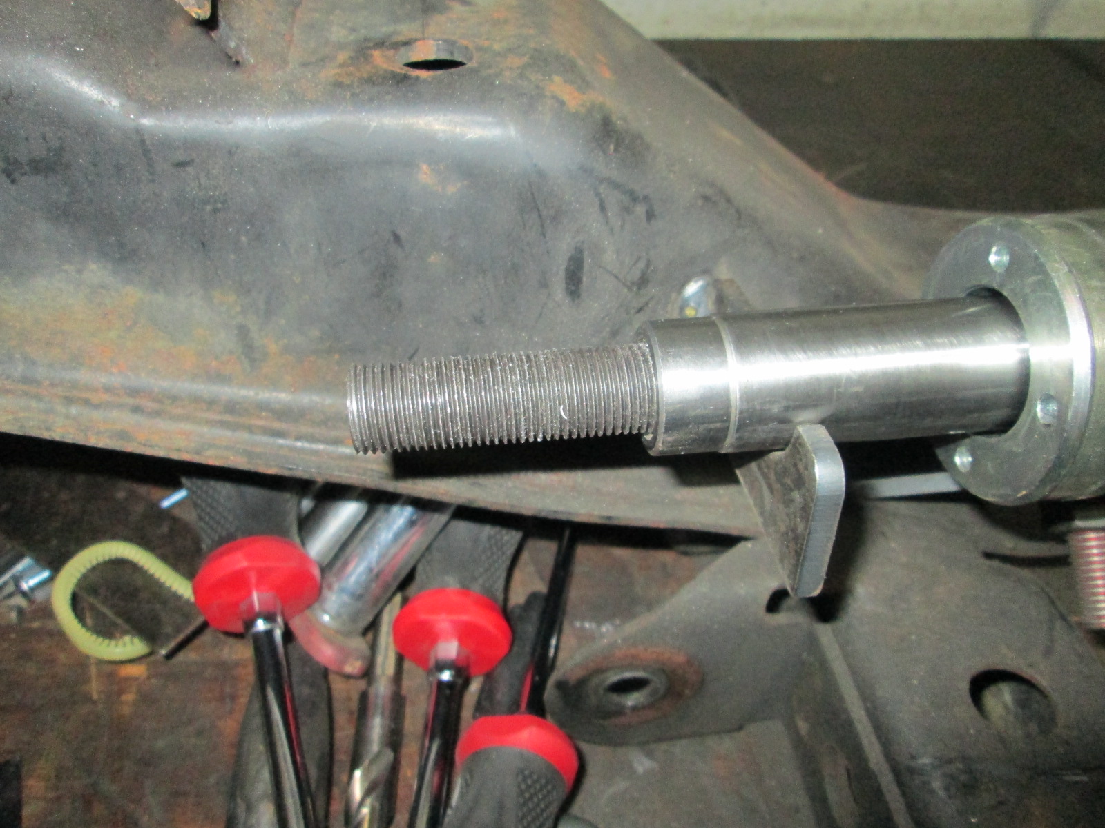
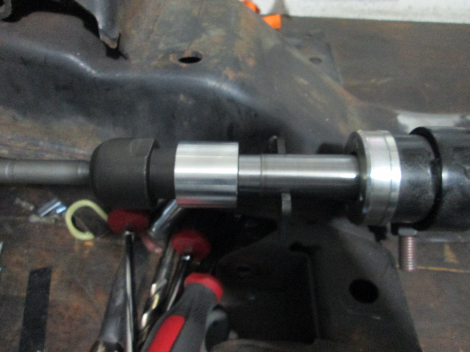
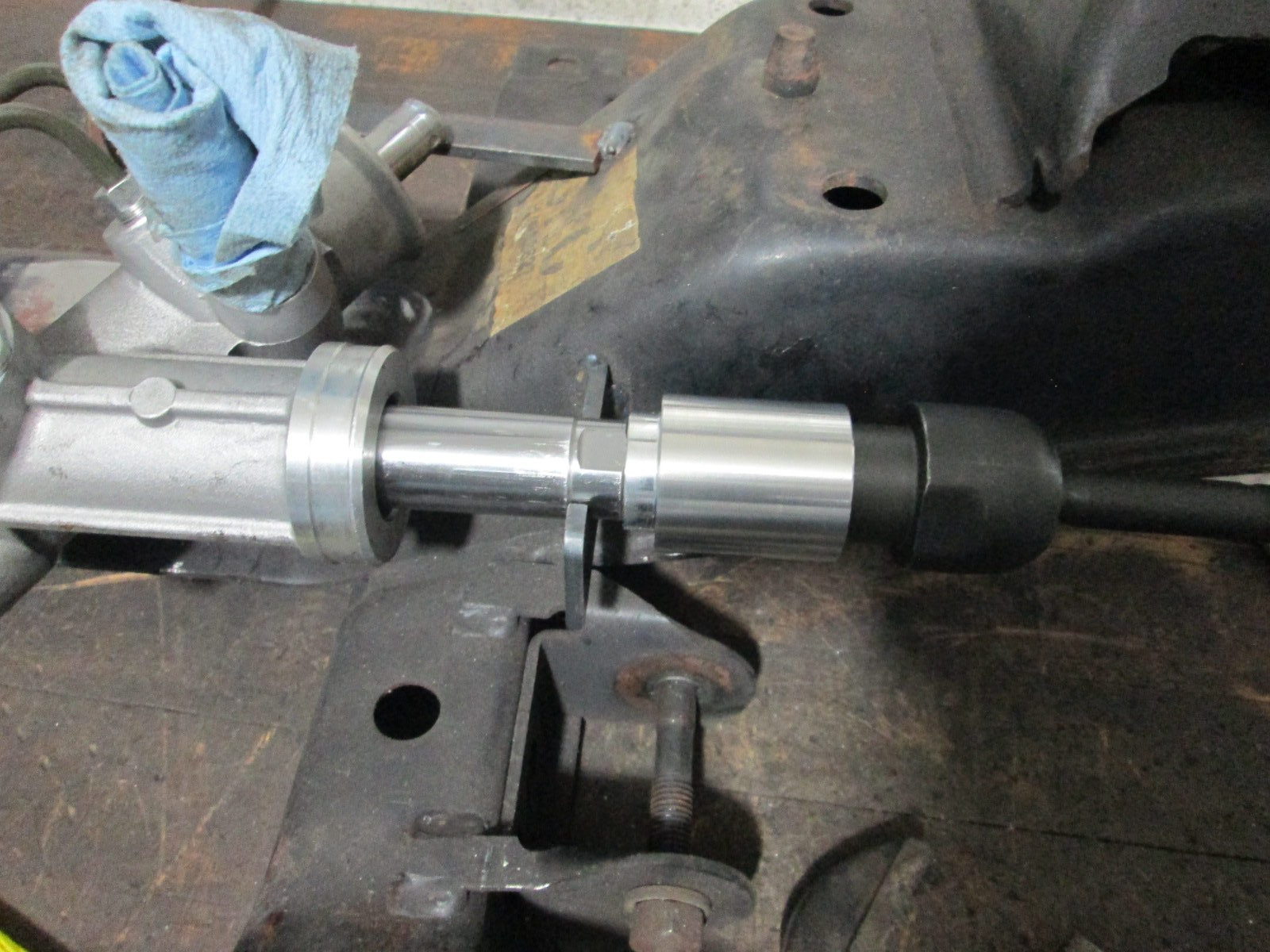
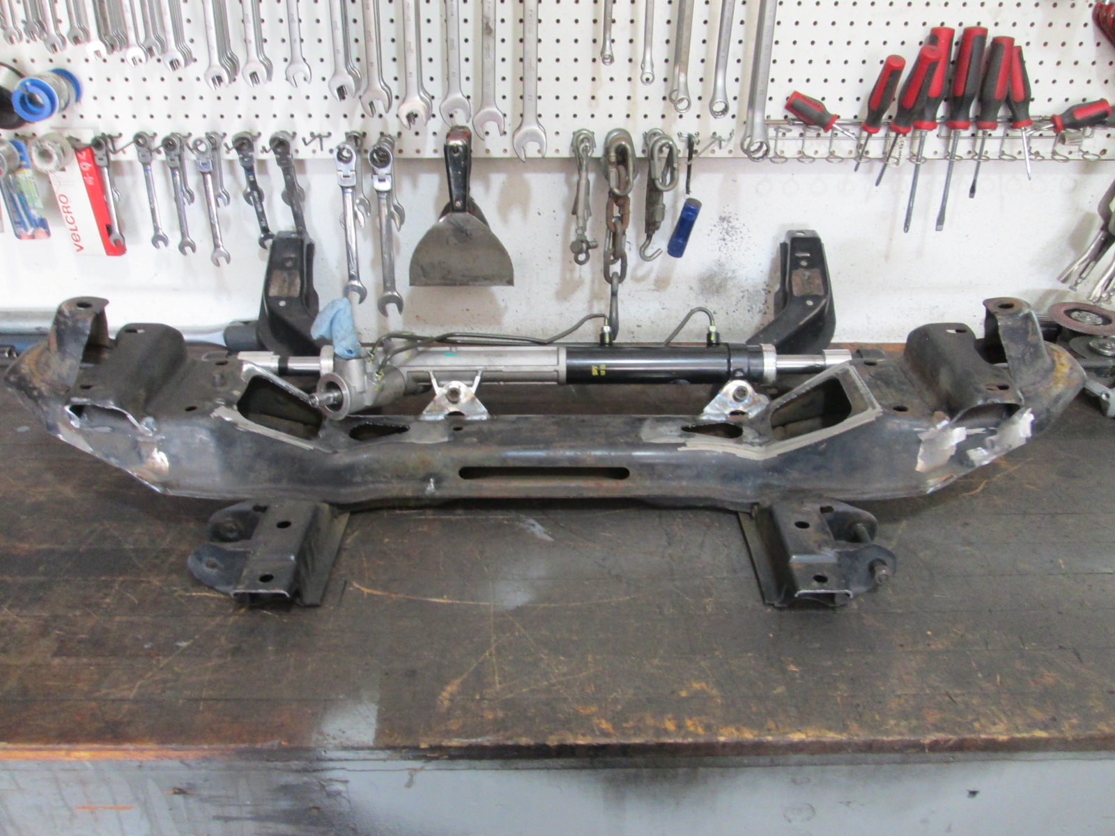
Steering rack extensions are 2 parts. Threaded rod to connect the rack and inner tie rods and aluminum tubes are spacers as well as rack stops. The aluminum stops allow a full 5" of rack movement side to side, just like the Fiero rack.
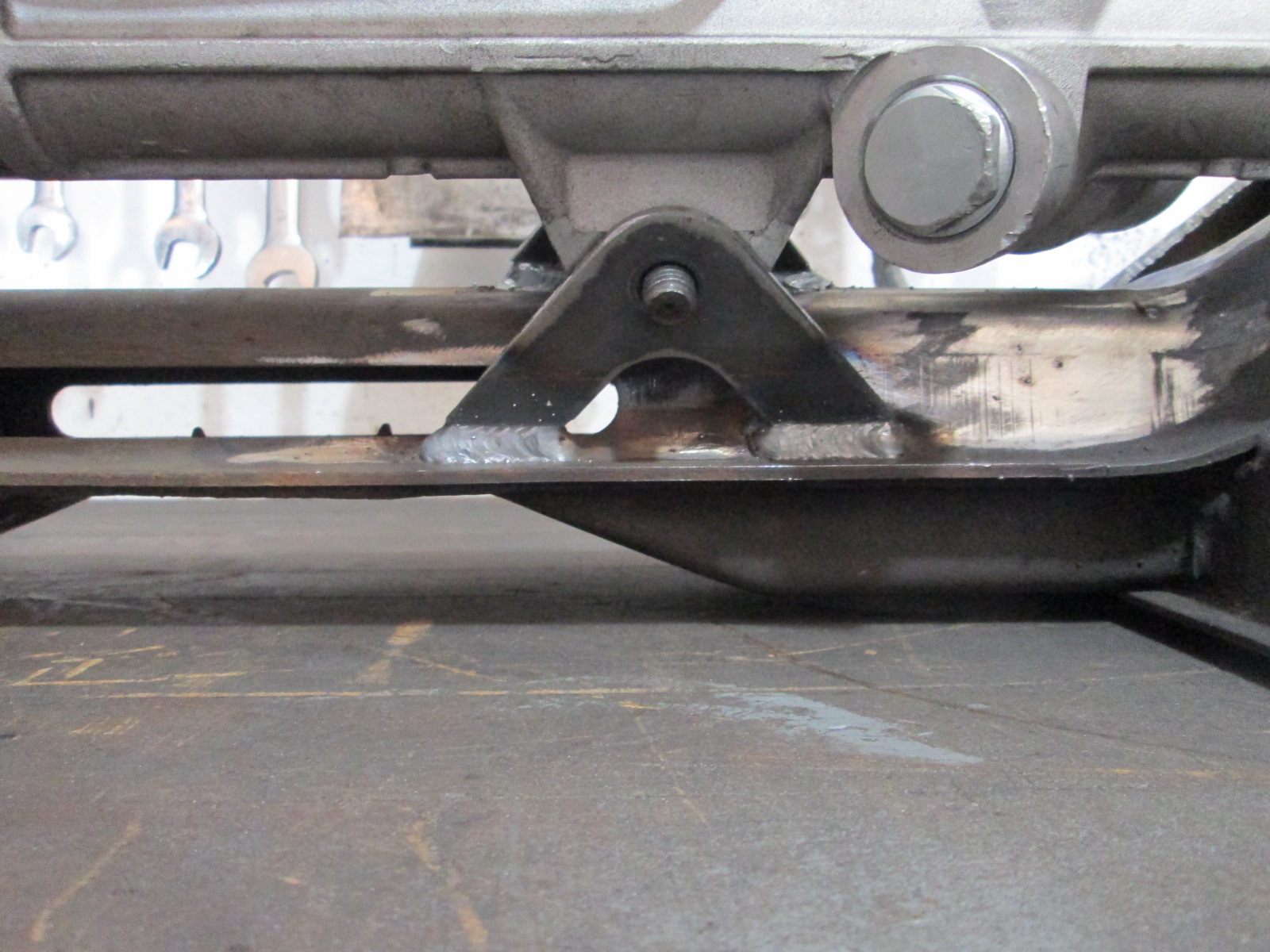
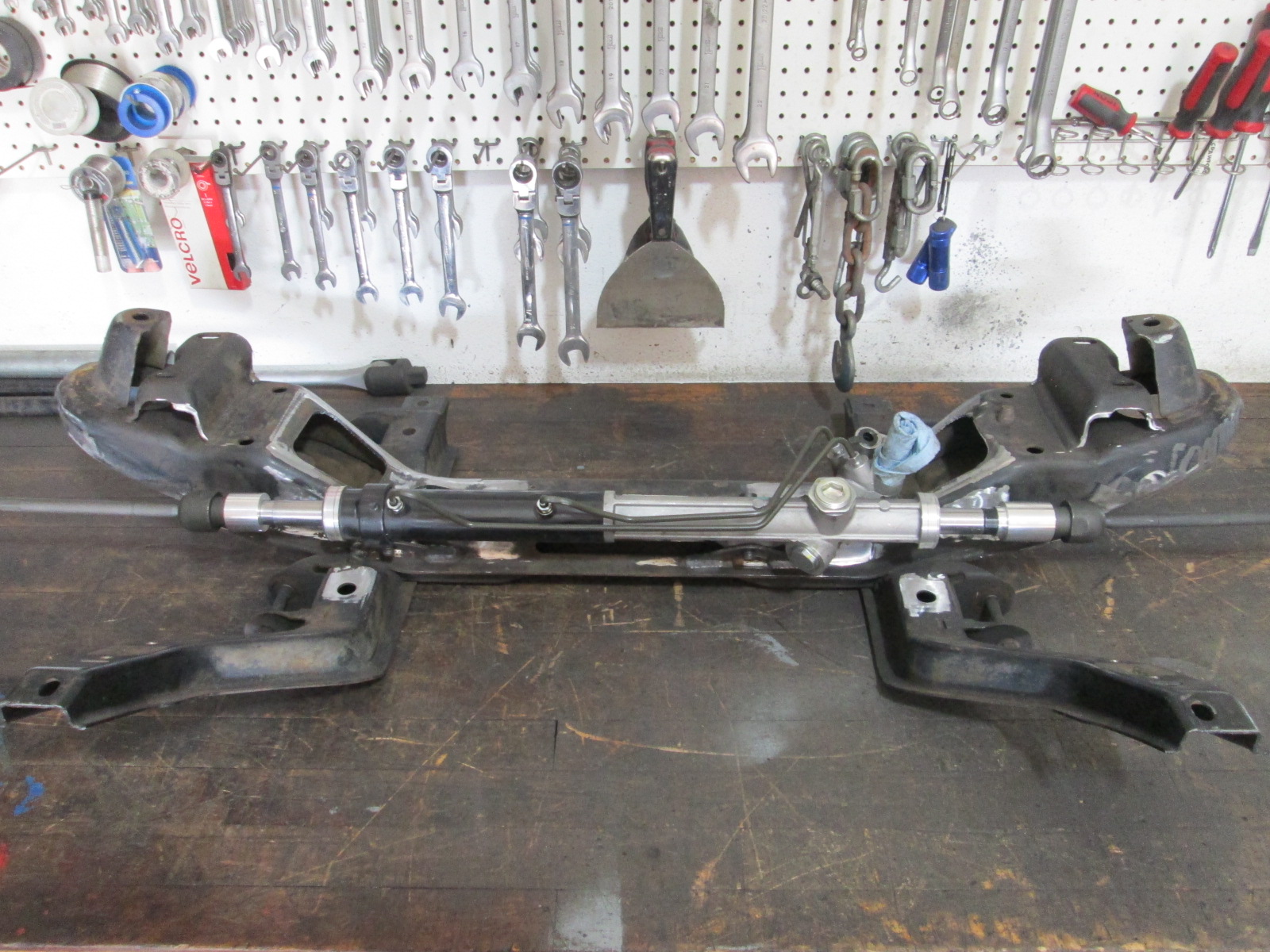
Finalized the side to side placement of the rack with it centered in its range of motion as well as the center between the inner tie rod pivots aligned with the center between the front lower control arm bolts. Remade the brackets one last time to take some weight out and welded them in place.
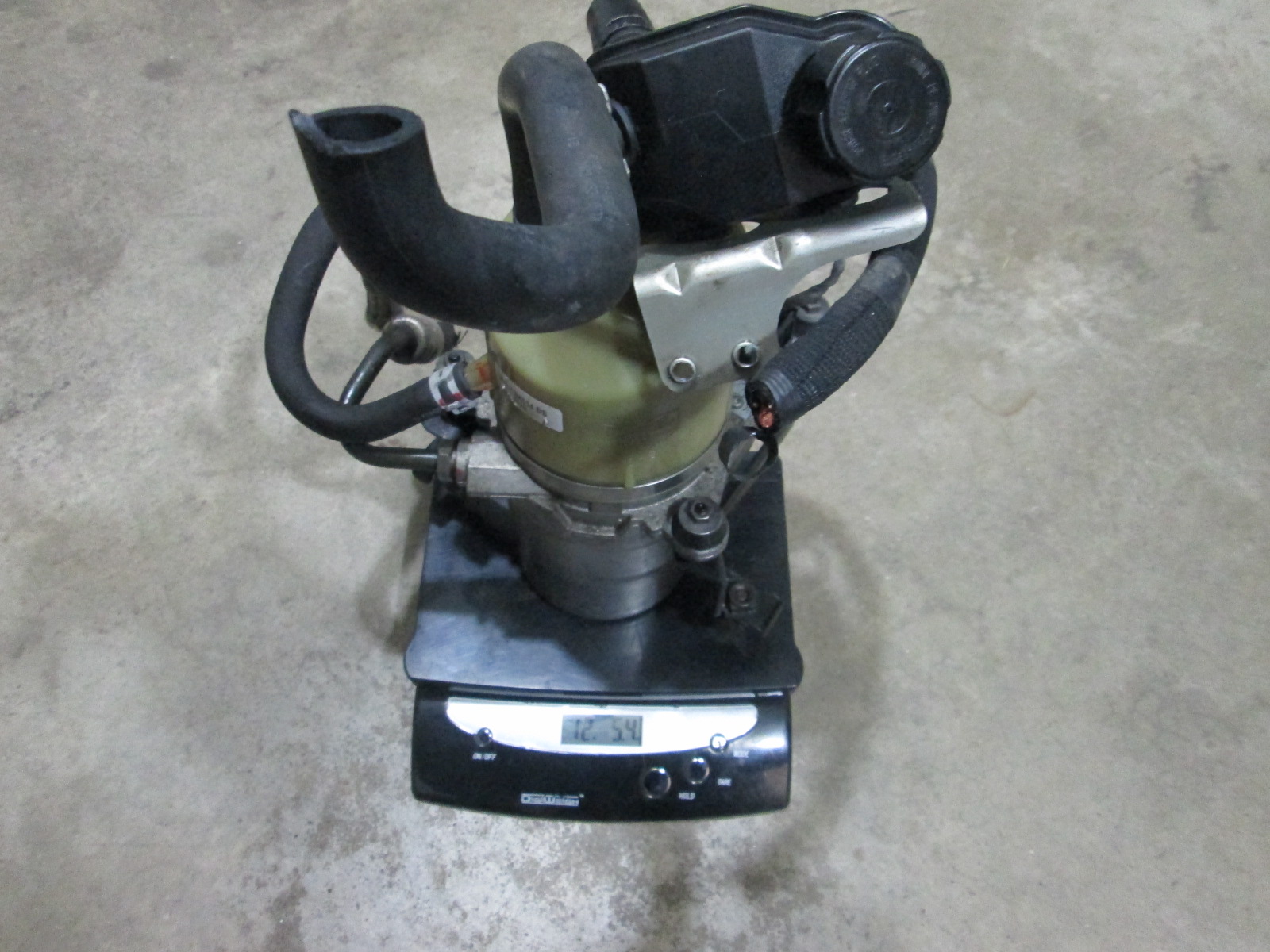
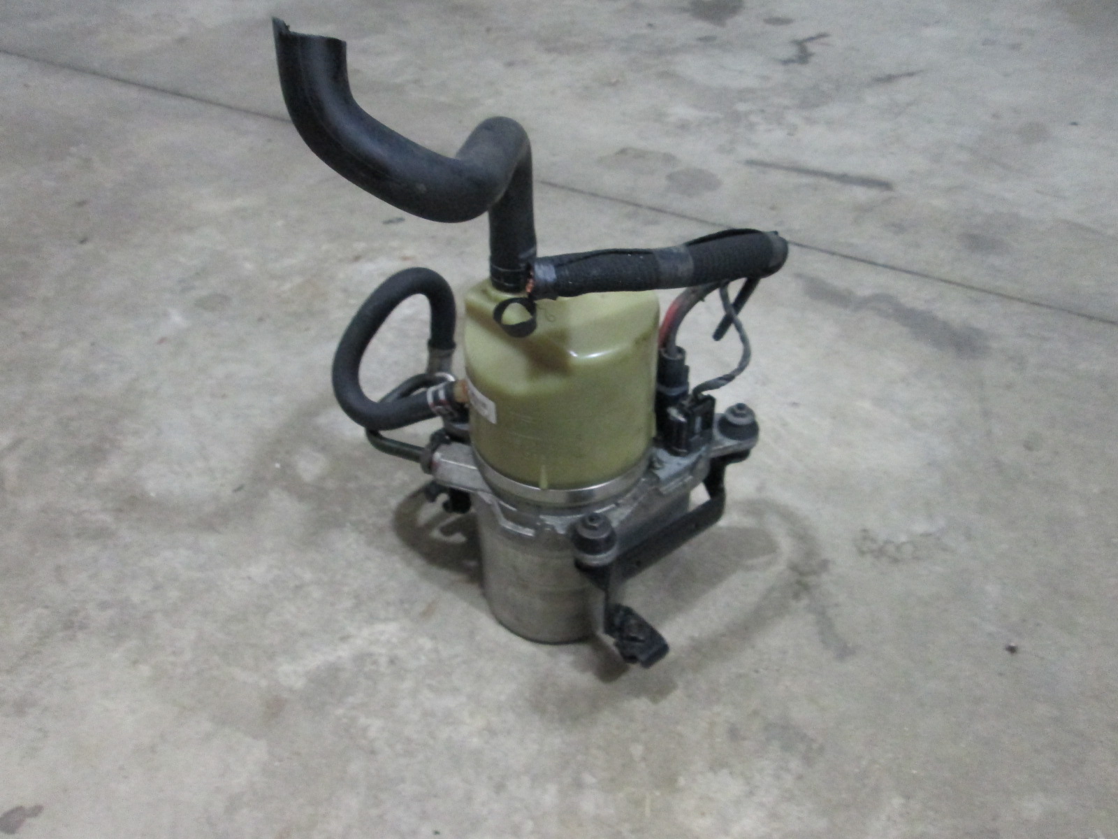
The power steering pump I have currently is the volvo unit that is commonly used for conversions. W/o fluid, it weighs in at 12 lb 5 oz. The power rack is also 1 lb 13 oz heavier than the Fiero rack, so the front will likely be about 15 to 16 lbs heavier with power steering.
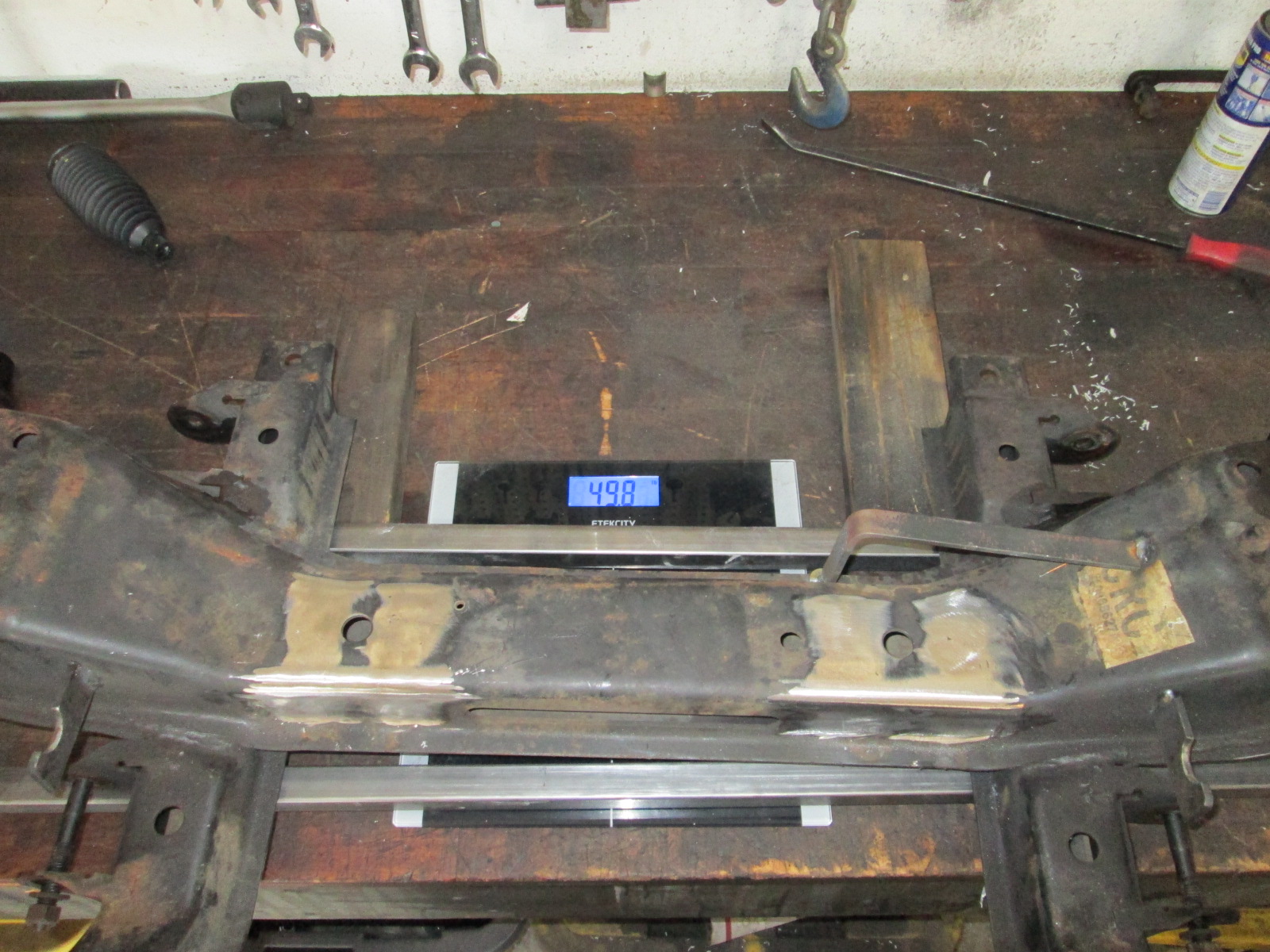
While the crossmember is on the bench and since it weighed 49 lbs 8 oz bare, I decided to use it to help offset the increase weight up front due to the power steering upgrade.
The spring pockets definitely were deeper than needed - so a nice angle cut to remove some of it was made. The upper a-arm stand had some excess metal on it as well, so it was trimmed back. I needed an opening for the front CVs for the future AWD project, so a couple of large openings were cut out.
There are several more sections of this crossmember that could have some speed holes added... so I an not done with this process yet. I might also cut the spring perches off entirely so I can run a lighter weight coilover setup.
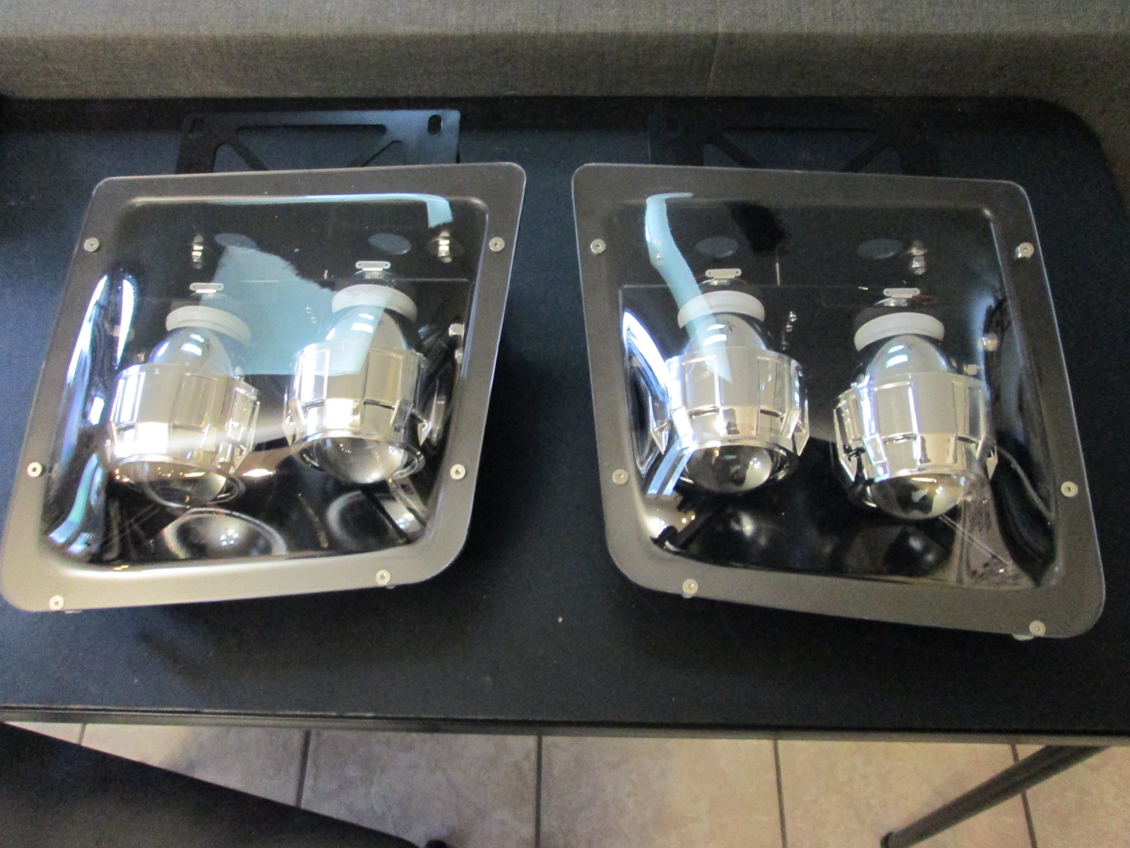
I also went ahead an picked up another headlight upgrade from doublec4... I already have a used original Fiero1Fan setup on the shelf, but figured I would pick this one up as well. I haven't weighed it yet, but it should be lighter than the stock fiero popup setup.
With the temps starting to drop and wanting to get the engine back in the work bay and out of the car for winter to finish everything, I diverted my efforts to the items I need to finalize at this stage of the drivetrain test fit.
Cold side... took some measurements and ordered some additional bends. It will be 2 1/2" out of the turbo, two 90s to offset the tube close to the strut tower, 2.5" to 4" transition, LS7 MAF, 90 turn before entering the throttle body and into the intake. Here is a very crude paint representation:
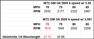
Also worked some more on the exhaust... When the car had the 3.55 final drive, it didn't have any noticeable resonance when cruising in 6th at 70 mph. When I swapped to the 3.091 final drive, the car was noticeably louder at 70 mph due to resonance and it dropped off as the car got to 80 mph. Since i am going with 3" exhaust, resonance will be worse, so I want to use a helmholtz 1/4 wavelength resonator and have used my prior observations of resonance rpm to help narrow down the expected length needed.
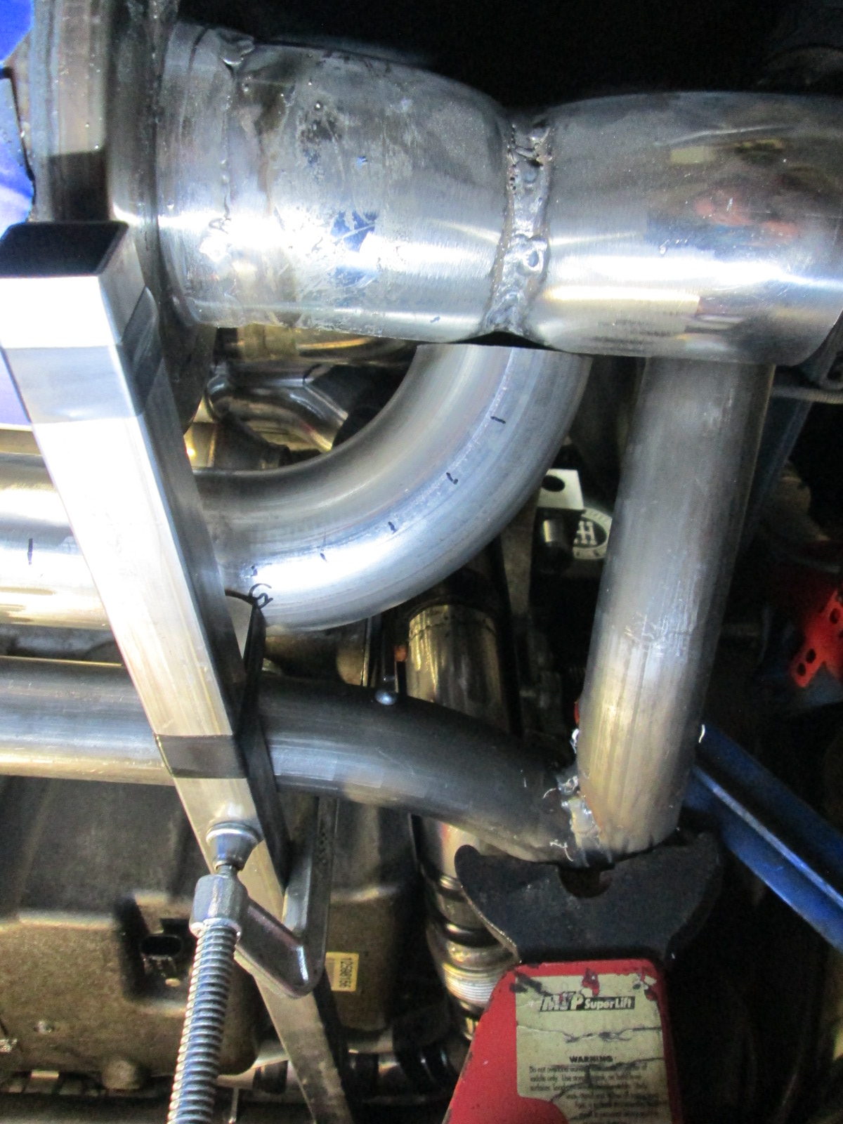
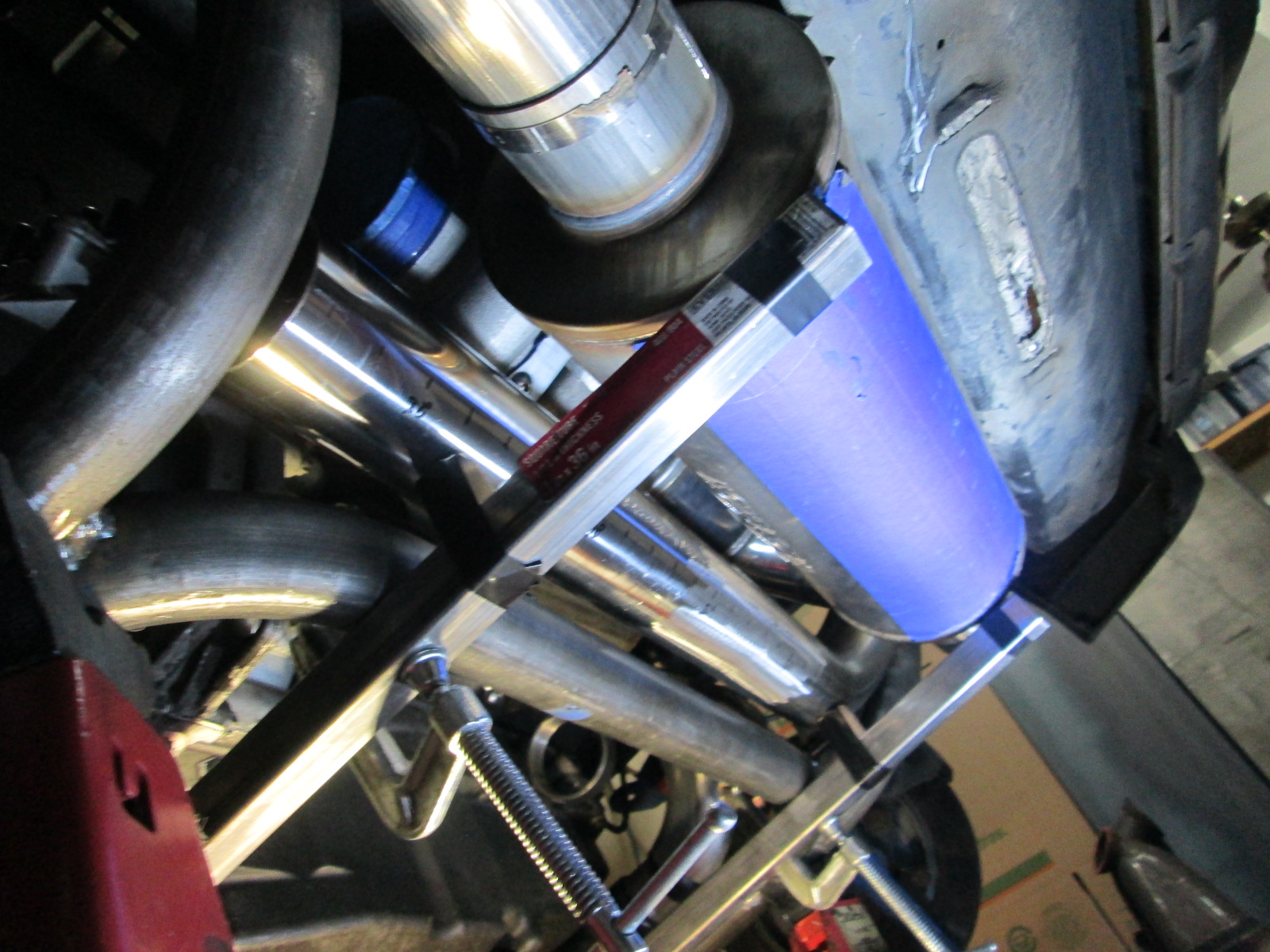
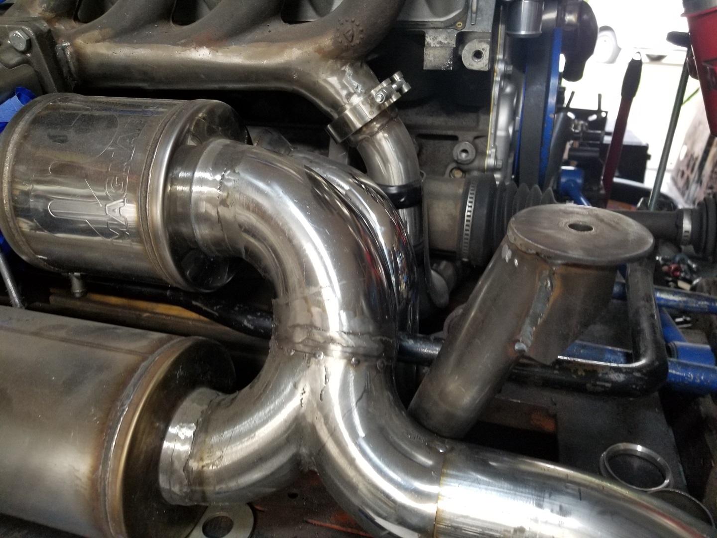
I had talked about using the cutout on the passenger exhaust tube to act as a resonator, but there is just too much pipe to fit in that area. Instead, I will route it parallel to the muffler between the muffler and cradle rail. Here it is setting in place. It is about 27 3/8" in length, which should work. It will come off the exhaust at the Y section where the 3.5" splits to dual 3" exhaust tubes.
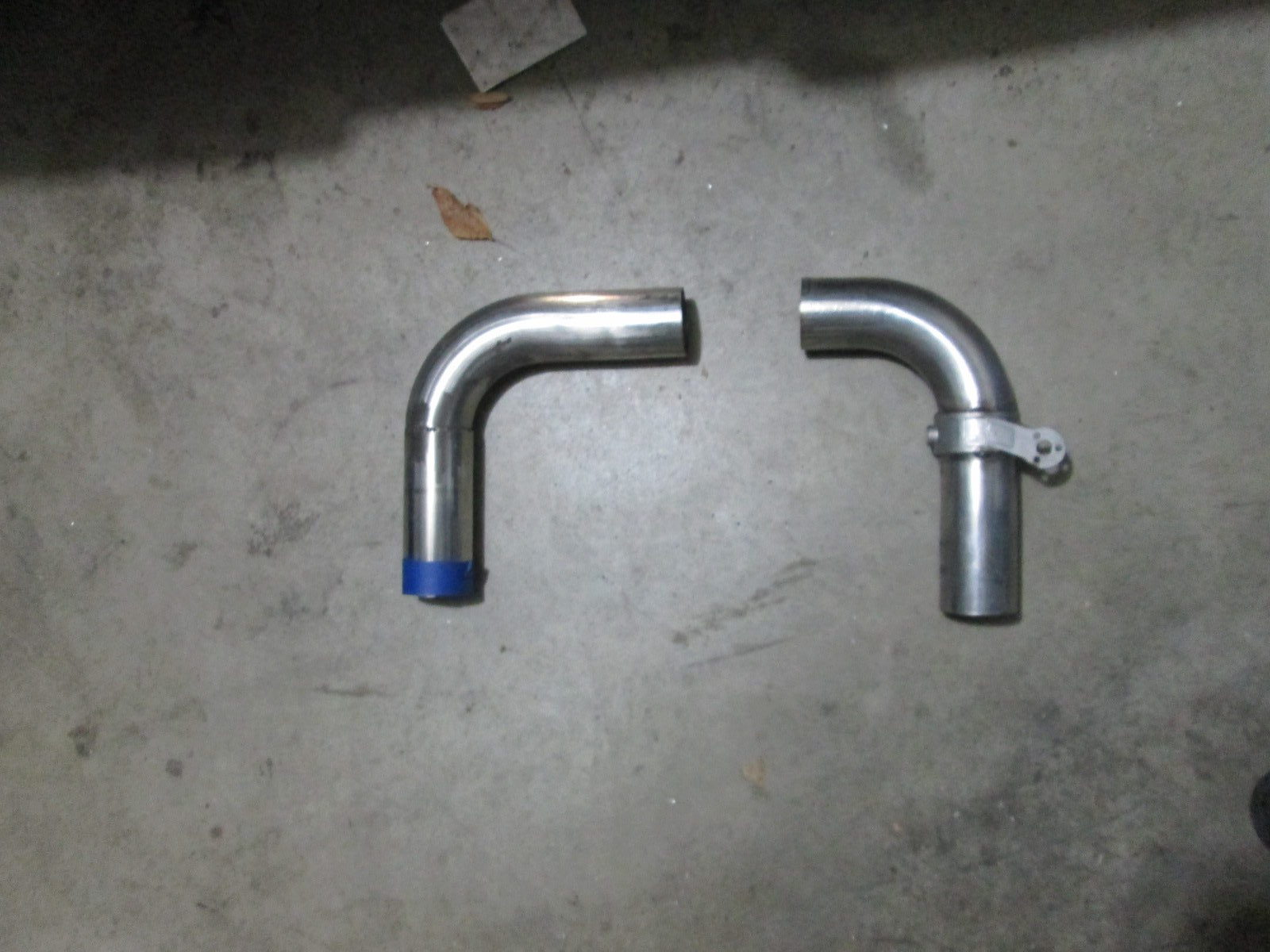
Now that the resonator plan was in place, I could started installing the cutout on the passenger side exhaust. The picture below shows the DS and PS exhaust pipes with the PS pipe having the cutout assembly. Still some final fitment and trimming needed, but things are starting to come together.
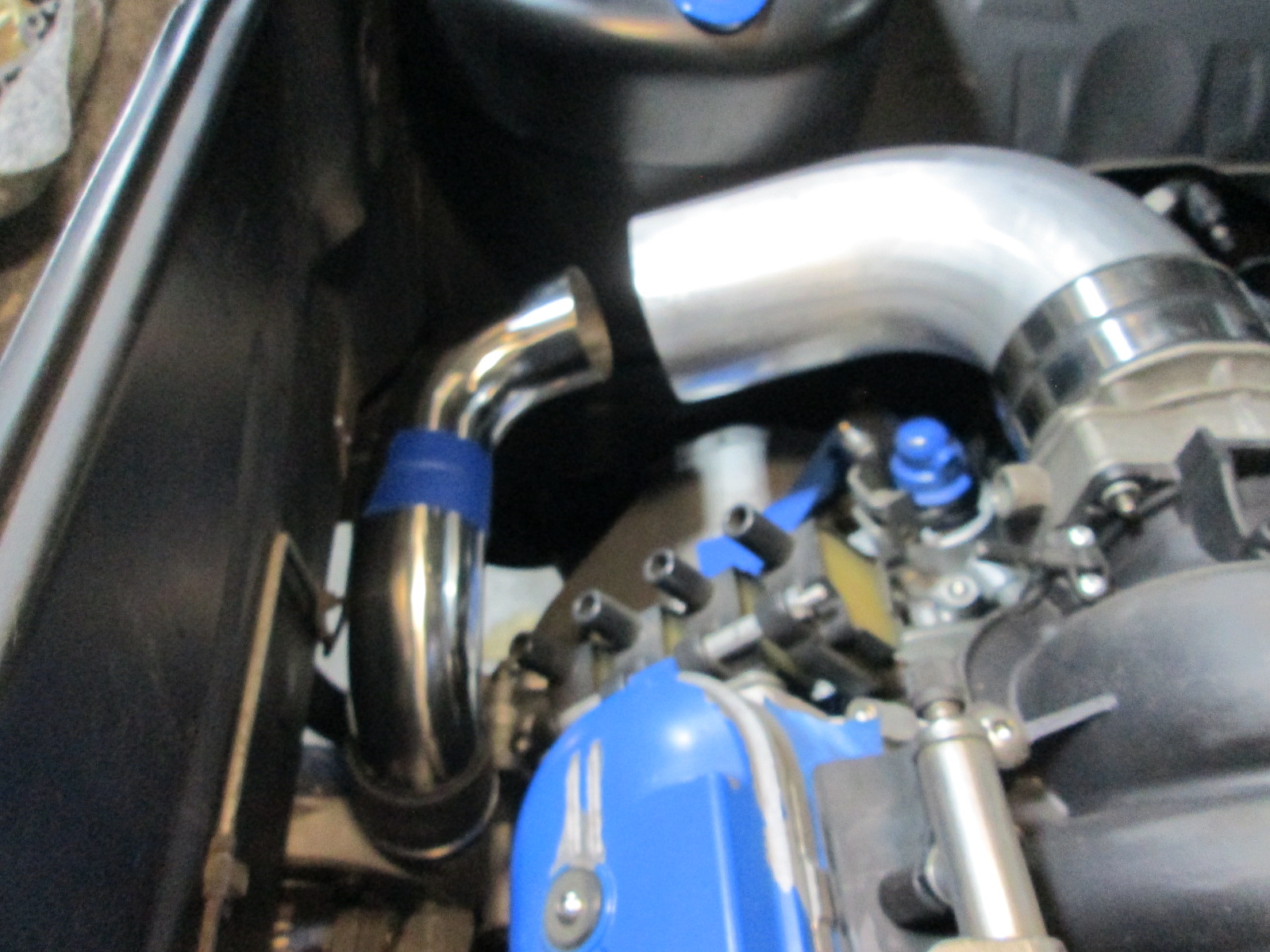
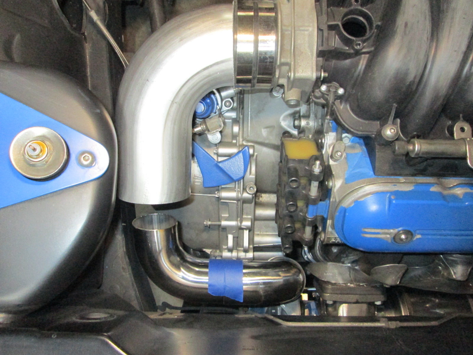
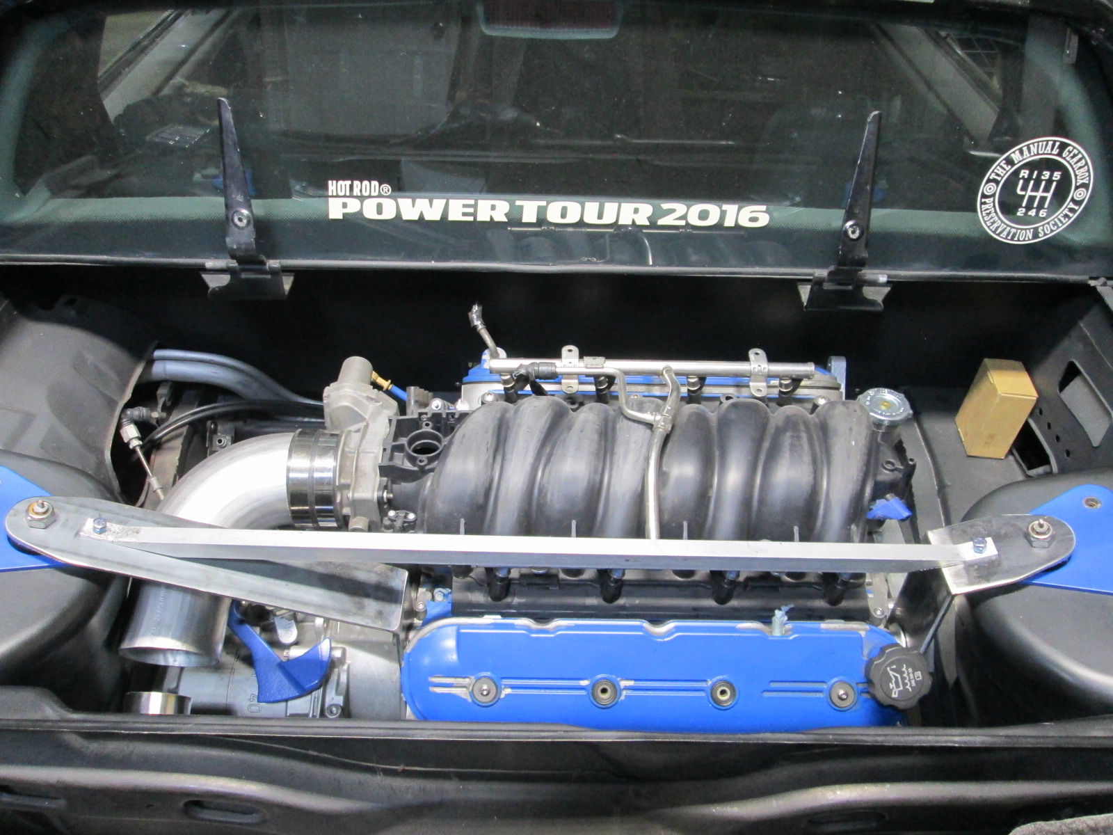
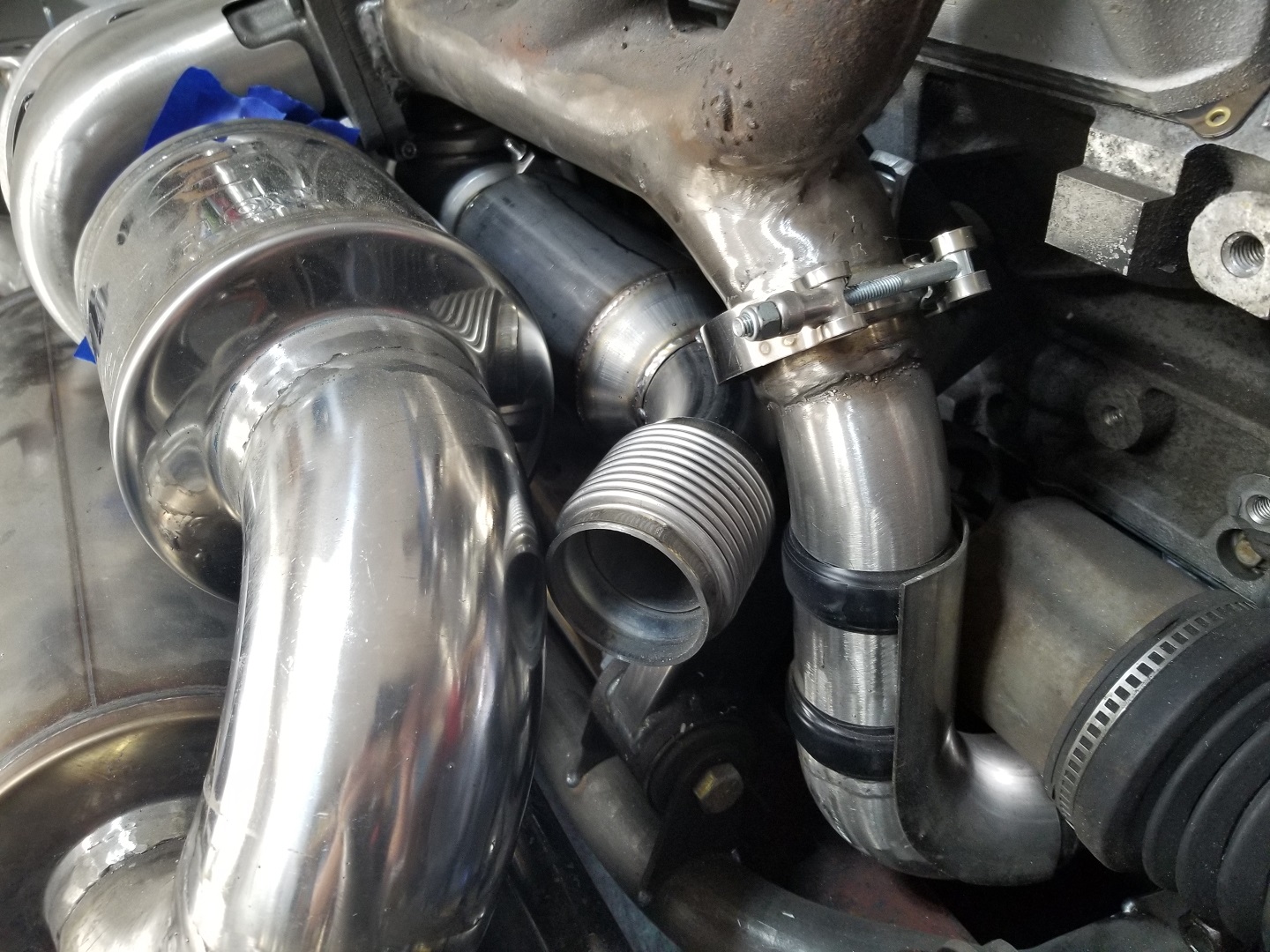
Mocking up the cold side. I think I will trim the hose barb off the turbo outlet and use a V-band setup on that end. This will allow me to lower the 2.5" side about 1.5 to 2", increase the incline angle from the turbo and throttle body tube and maximize the length of the 4" section.
This is mocked up enough to know 4" section will clear the strut tower (especially when angled down some more, so the rest of it can be finished on the stand.
I had a few hours today to accomplish more with the exhaust.
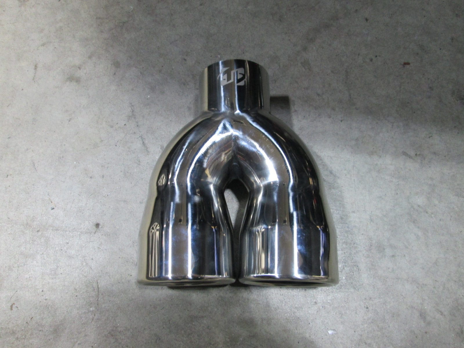
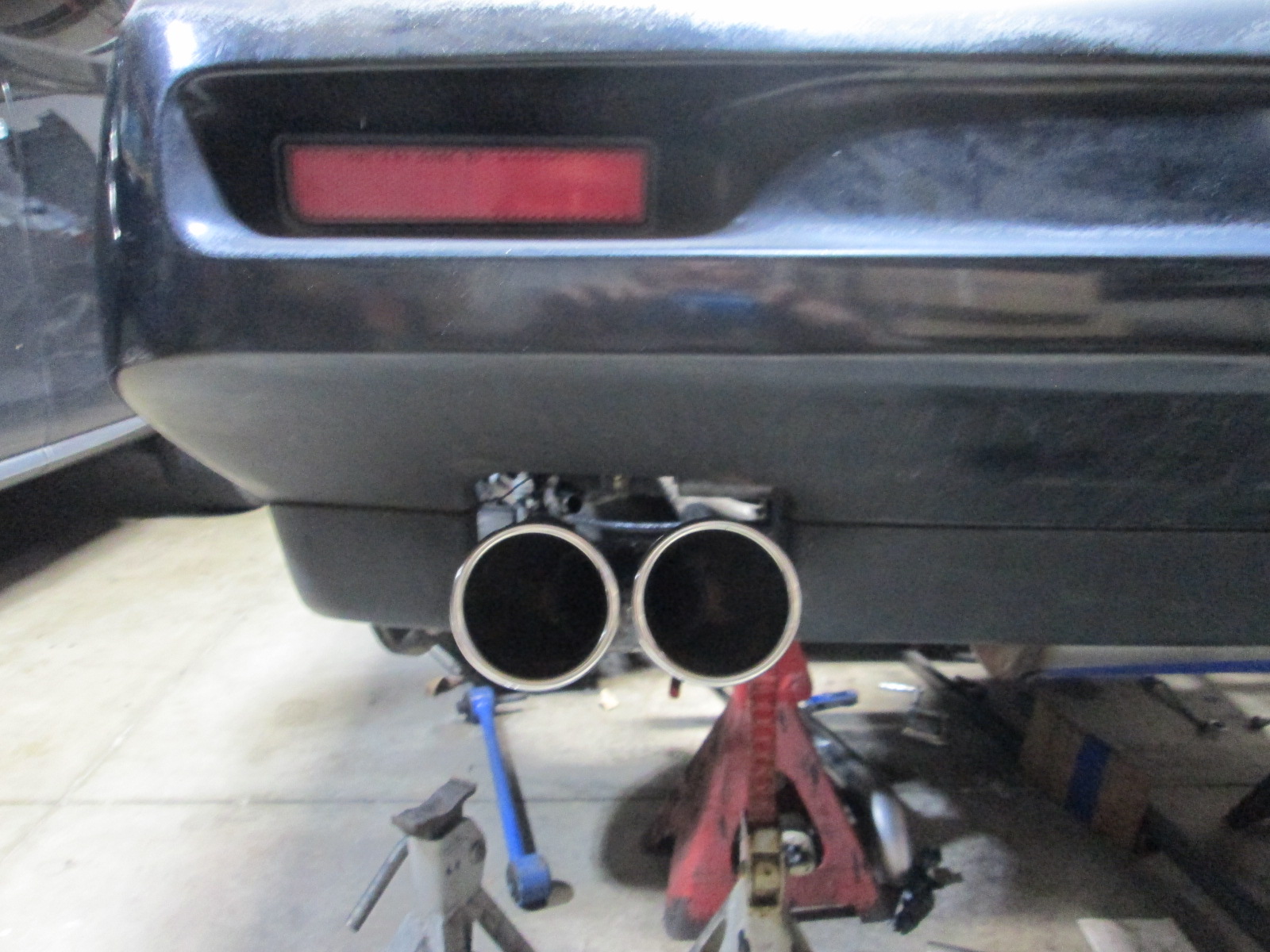
While I have always used the stock megaphone tips, they are only dual 2" tubes and would be a restriction for the 3" tail pipes. I found these stainless tips made from a 2.5" Y with dual 3" tips.
Cut the inlet off, oval the 3" tail pipe and some welding and it looks like this:
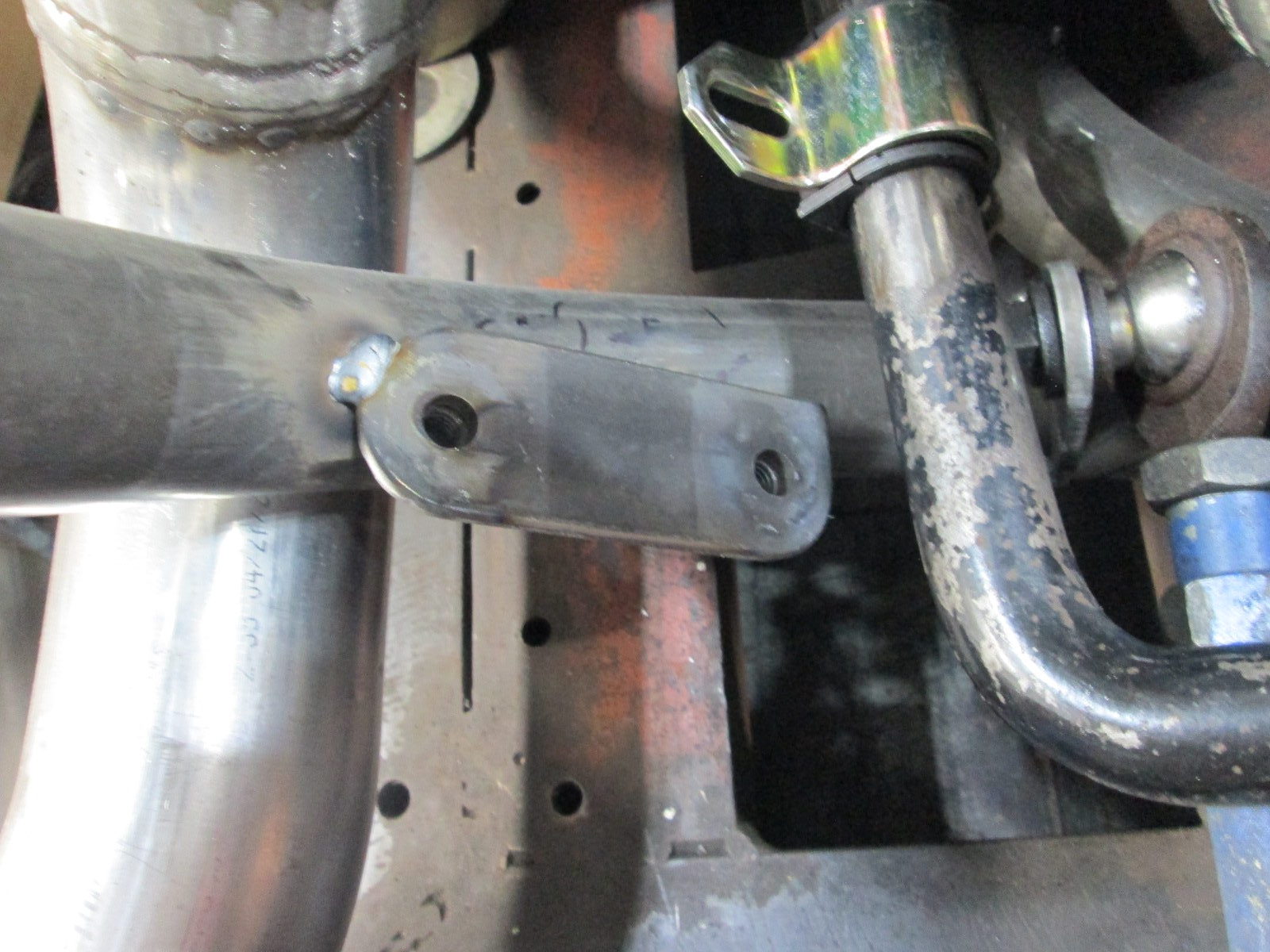
While the engine was in the chassis, I wanted to pickup the top of the struts so I could play around with sway bar placement.
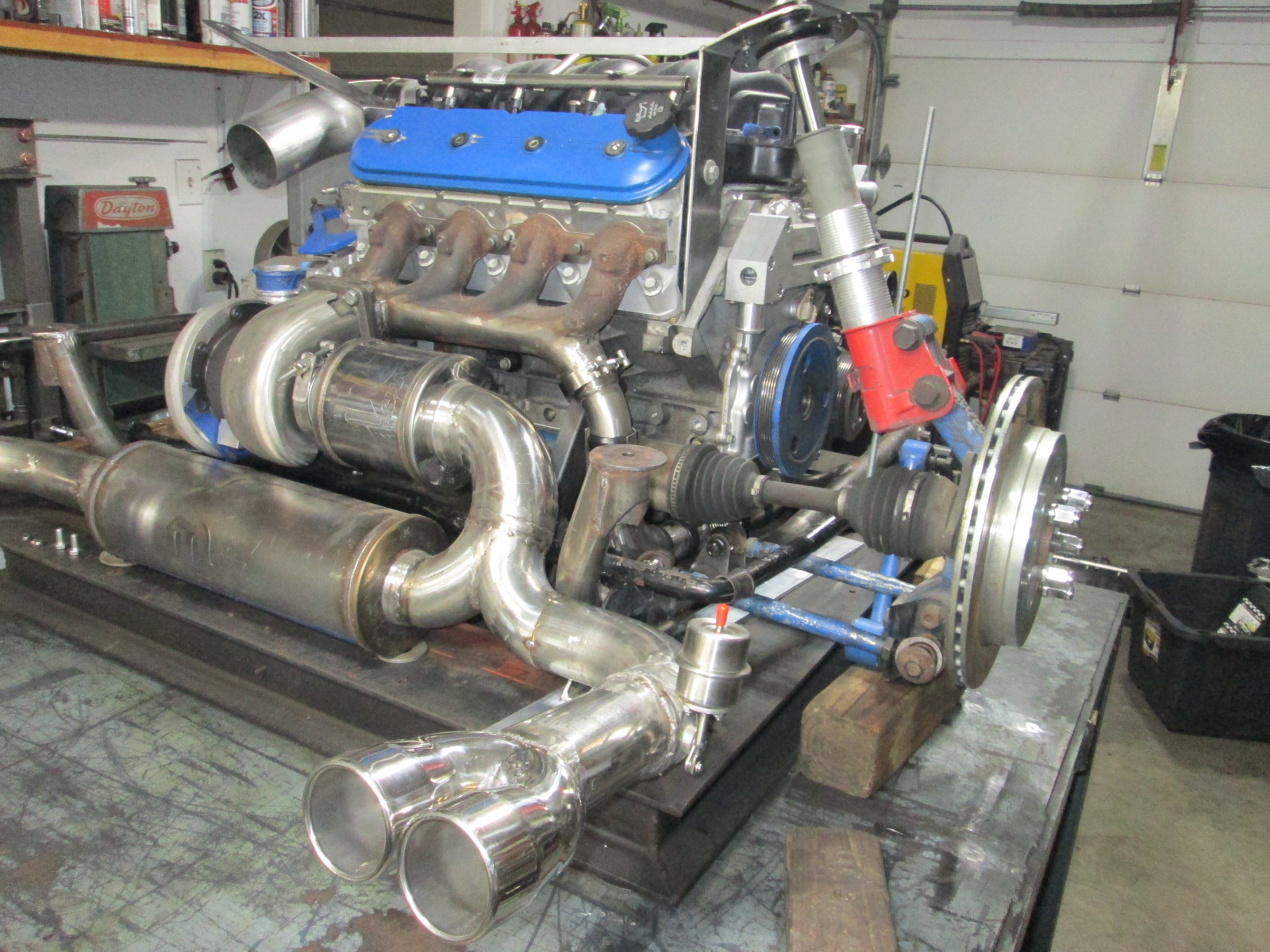
After those strut location brackets were done, it was time to put the drivetrain back on the table:
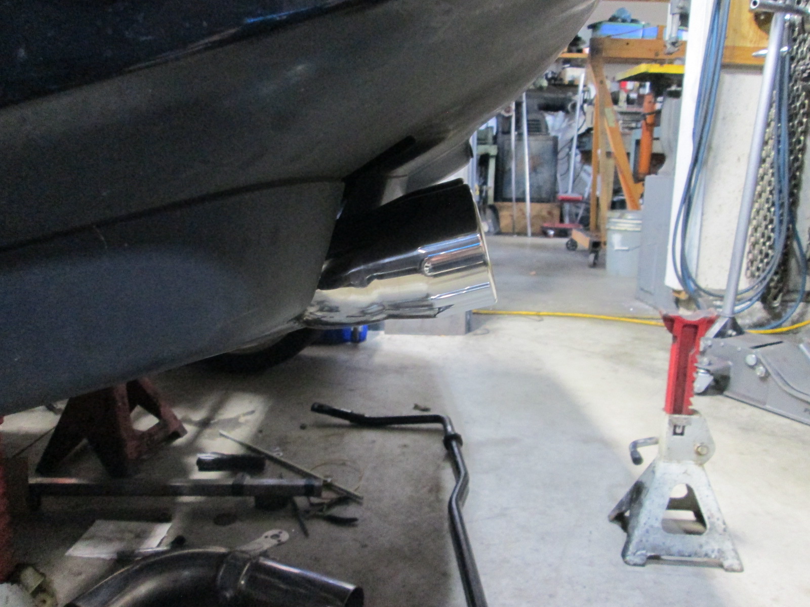
Here you can see the passenger side exhaust made with the vacuum activated cutout, as well as the suspension mockup at ride height.
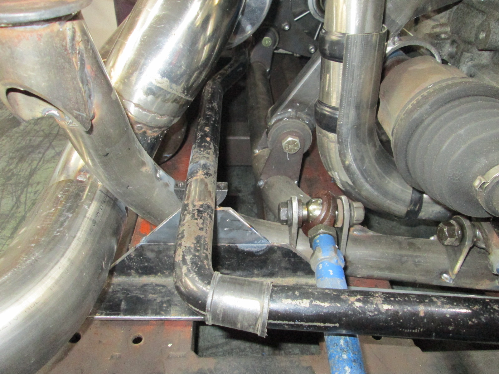
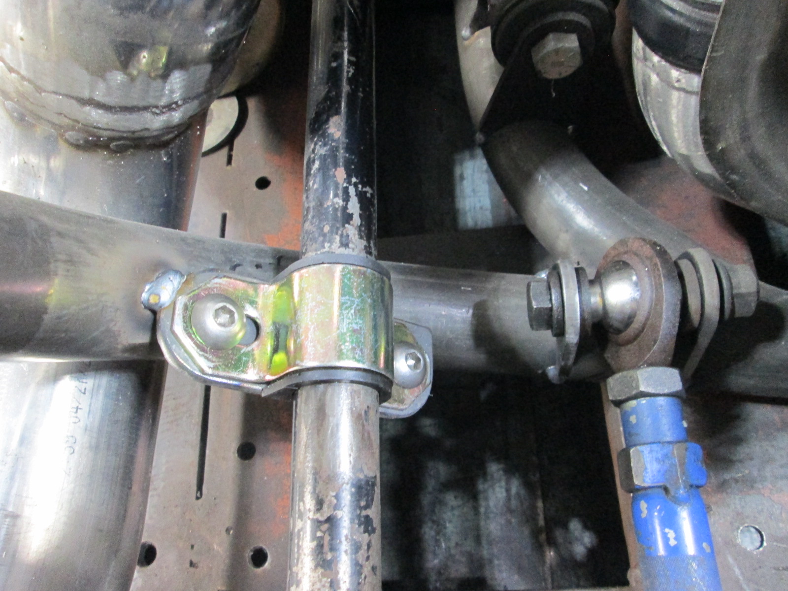
Since the turbo clearance required the tubular cradle for clearance to the rear crossmember, and the stock sway bar mounts above the rear crossmemeber, the turbo also requires the sway bar to be relocated several inches lower. This puts it too low to continue to go over the axle, so it was flipped over and positioned under the axle, but over the lateral links, which makes for a tight fit... but it does fit with adequate clearance for full compression and full droop!
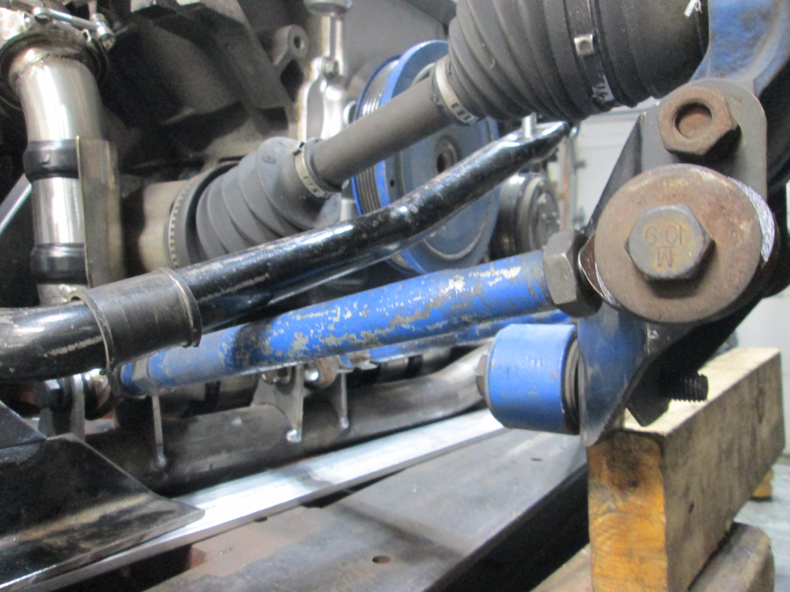
For the swaybar test fit, I quickly fabbed up a bracket to hold it in position. I will make another for the other side to fine tune the placement as well as verify with the driver side as well (it has a shorter axle, so geometry will be slightly different and will likely be the side the ultimately sets the final position and overall length of the end lengths.
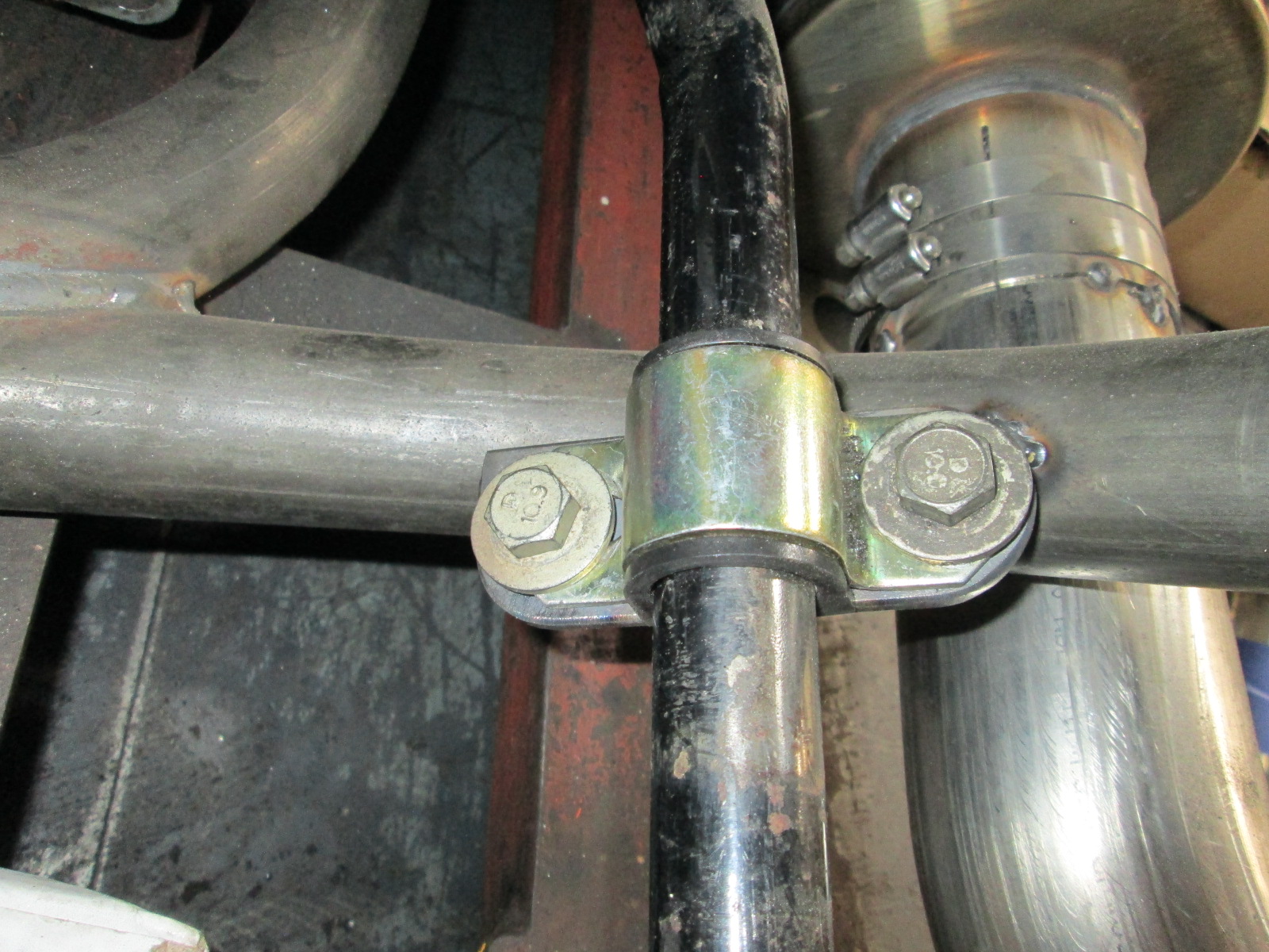
At full compression, the bar clears the lateral link and axle.
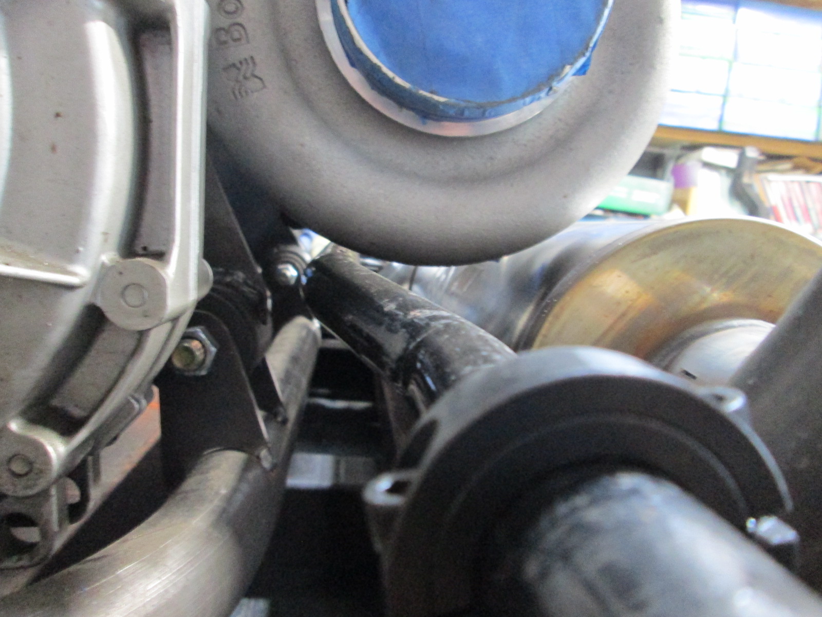
Here is the clearance between the sway bar and compressor housing:
So most of the time your exhaust will be going through the left side, which has an additional muffler, which will make things nice and quiet. When you jump on it, the cut-out will open up to make sure you don't have a exhaust choke. I get that. Your vacuum cut out, how will that work? Will it function off vacuum from the engine, or will you have a separate vacuum pump and a switch to operate?
Sorry if you posted that elsewhere already and I missed it.
I am not convinced on the drivers side actually being quiet... but I have tried to maximize the length of unrestricted muffling. I don't think I will be able to drive it to work daily. Neighbors probably won't like hearing it pull out of the driveway at 4:30 am.
There will be a vacuum reservoir by the cutout which will be maintained by engine vacuum when not in boost. A 12v dc mac valve will be used to apply vacuum to open the cutout on demand - it is spring loaded closed for 90% of the time.
I could use a pressure switch for condition based activation, but I think it would be really cool to have a go baby go button on the shifter!
Used the plasma table to make something nice for Sara. It is about 22" x 22', took 5 solid minutes of cutting and about 500+ lines of g-code. Definitively the most complicated part I have cut so far:
Nice! I made the first cut on mine yesterday, I think it is probably fairly recognizable around here! I ended up with the Crossfire Pro, and a Hypertherm Powermax 85. need to work on getting everything a bit more dialed, but it works. Thanks for your help and advice!
------------------ "I am not what you so glibly call to be a civilized man. I have broken with society for reasons which I alone am able to appreciate. I am therefore not subject to it's stupid laws, and I ask you to never allude to them in my presence again."
Nice! I made the first cut on mine yesterday, I think it is probably fairly recognizable around here! I ended up with the Crossfire Pro, and a Hypertherm Powermax 85. need to work on getting everything a bit more dialed, but it works. Thanks for your help and advice!
Congrats! The Pro and Powermax 85 will be a nice setup!
Once you get it dialed in and master the drawing/conversion to cut files, it will be a game changer.
It is one of my favorite tools now.
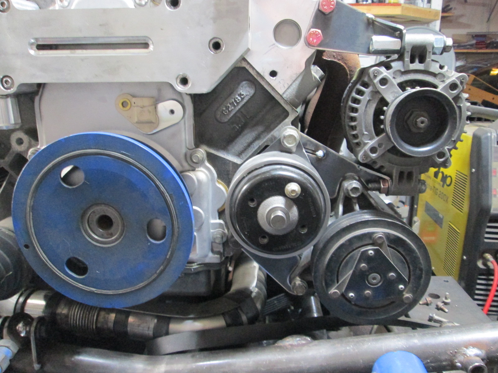
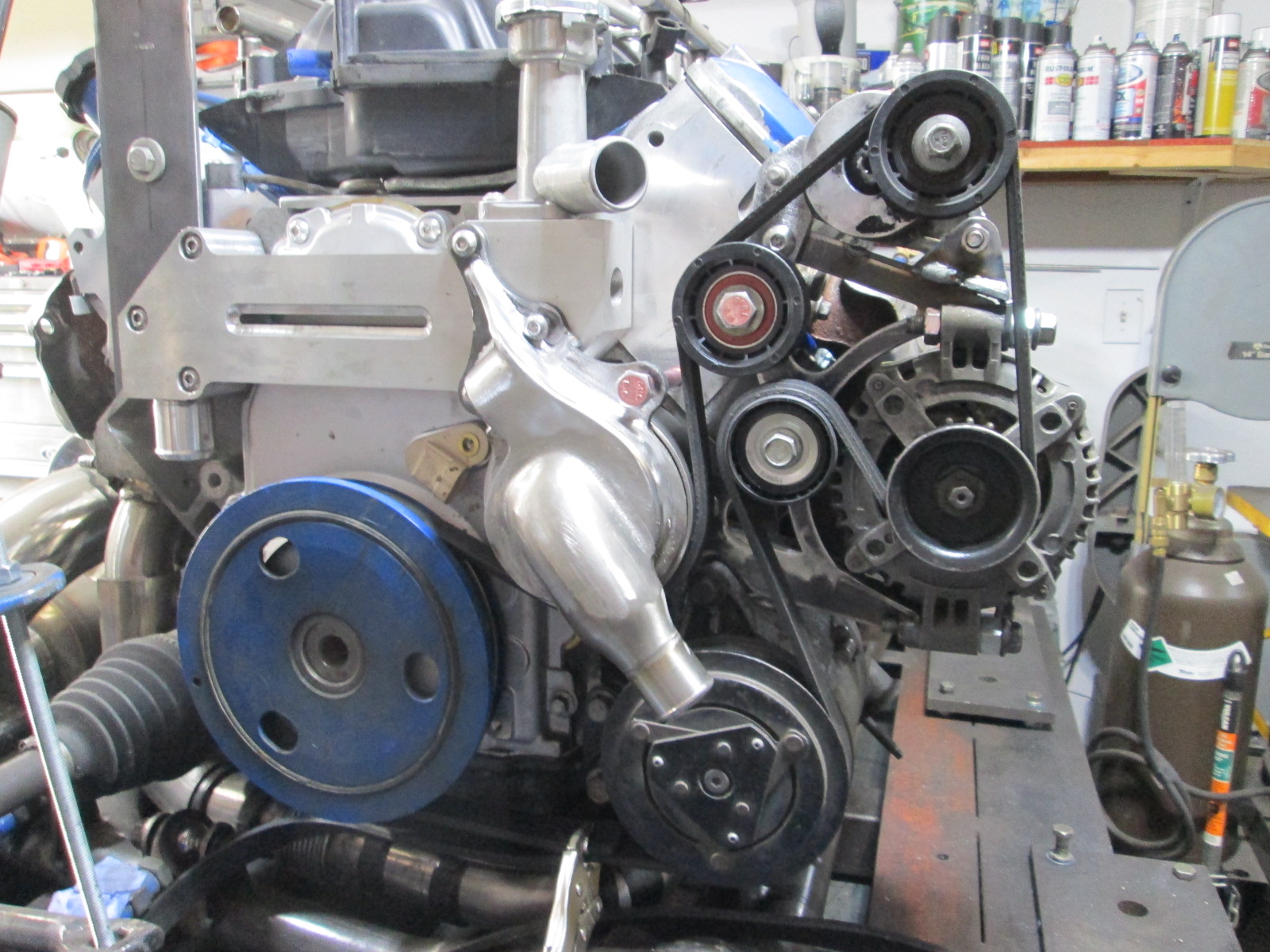
It is great to have drawings of parts, move them around in cad, make a cut file, and assemble the parts. Reworked the AC brackets to make room for the water pump (and the bracket to mount the water pump) in an hour or two this weekend. It is really making me change how I think about mount and bracket design.
Finally pulled the trigger on a new tig machine. I have been super pleased with my Lincoln Promig 175 (2007), so I am sticking with Lincoln for the tig as well. Not sure when it will arrive. https://www.harrisweldingsu...-for-a-limited-time/
Finally pulled the trigger on a new tig machine. I have been super pleased with my Lincoln Promig 175 (2007), so I am sticking with Lincoln for the tig as well. Not sure when it will arrive. https://www.harrisweldingsu...-for-a-limited-time/
when I started reading this, I was almost worried you would say "Diversion 165/180", I had one for a while, and it worked, but it wasn't working at what the $3000 price tag should have bought. I've heard really good things about the Lincoln Square wave machines! I recently bought a Primeweld Tig 225 to replace my broken Diversion, having the ability to adjust bias and frequency is a game changer on aluminum!
------------------ "I am not what you so glibly call to be a civilized man. I have broken with society for reasons which I alone am able to appreciate. I am therefore not subject to it's stupid laws, and I ask you to never allude to them in my presence again."
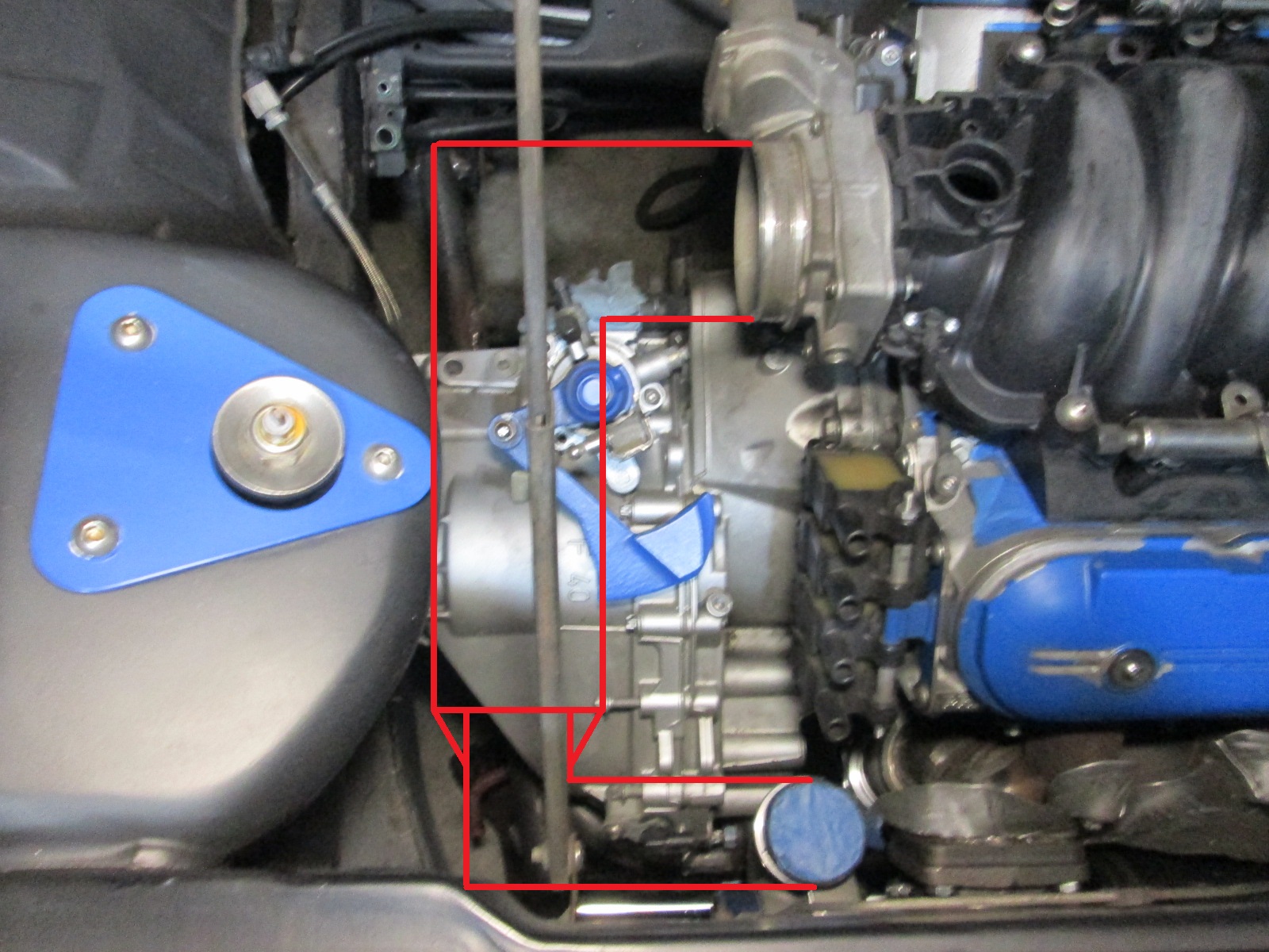
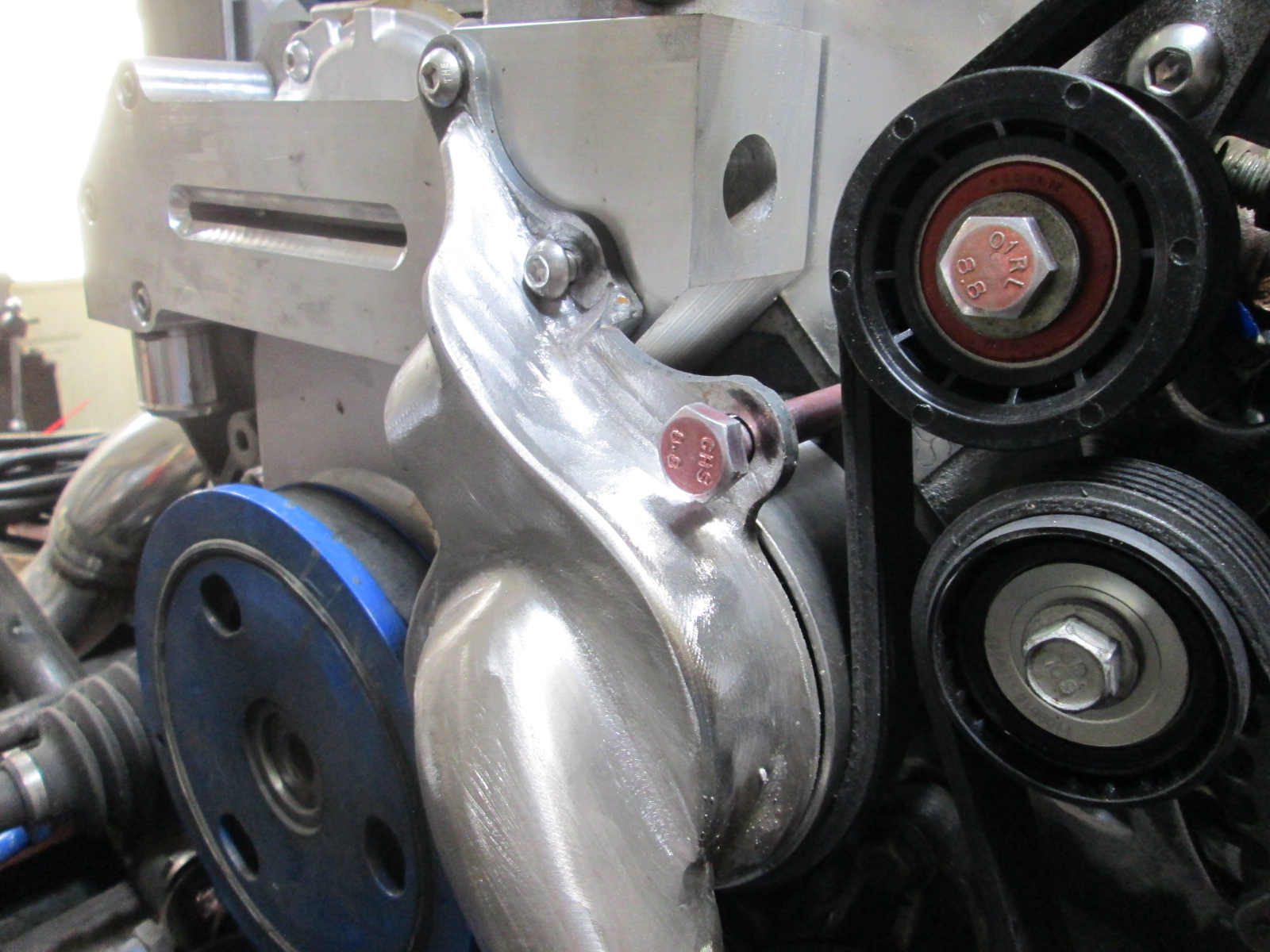
It is really hard to believe that I have been working on my LS water manifold since late 2017 (4.5 years). The manifold was the easier part, but the goal was always to have a mechanical water pump version for my car. This has probably been one of my most challenging swap tasks to date, as there is just not that much space to work within. I also kept myself restricted to the LS4 Alternator and AC compressor, which just added another layer of complexity with the Alternator mounting bosses. Lots of attempts, lots of scrapped metal and parts, and $$$ spent, but I finally figured it out and fabricated a workable mechanical water pump solution!
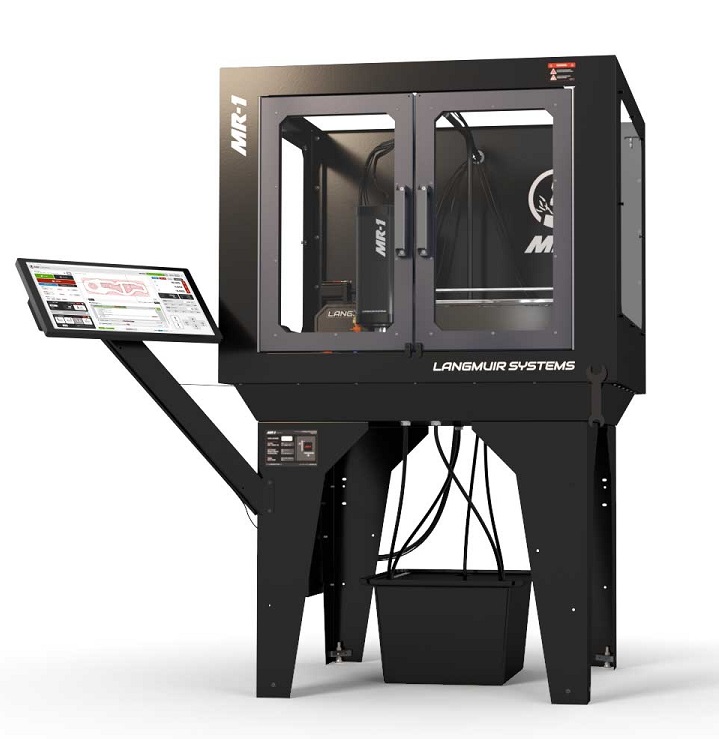
I am going to pull the trigger on the Langmuir MR-1 CNC Mill. It is 3.4 HP 220V single phase, has 22.8" x 21.8" x 6" machine travel, room for a 33" x 31" work piece, and a 48" x 55" footprint (with the enclosure) in the shop. I plan to get most of the options including the flood coolant, enclosure, 2 vices, some tooling, and tooling setting sensors, but will not get the touchscreen PC or the threading tooling (SAE and I would need metric).
This mill should be a good compromise between cost, capabilities, and shop space requirements. It should be large enough and capable of making just about any custom Fiero parts I could dream up...
[This message has been edited by fieroguru (edited 04-17-2022).]
Yeah, I think I see the number of rose-tinted glasses folks pinging FieroGuru with ideas and questions are going to go up quite a bit. ... I may or may not be one of those people.
FieroGuru, at this rate you're going to need to hire someone part time to help you keep up with your Fiero side hustle.
Yesterday was the pre-launch for the Langmuir MR-1. It opened at 3 PM Central and I placed my order/deposit at 4:30. Originally they were estimating the lead-times to start late August/early September, but my order is estimated to ship in the middle of December...
I am fine with the lead-time as it will let me get the wiring upgrades to the garage complete as well as give me time to reconfigure all the equipment to make the needed space.
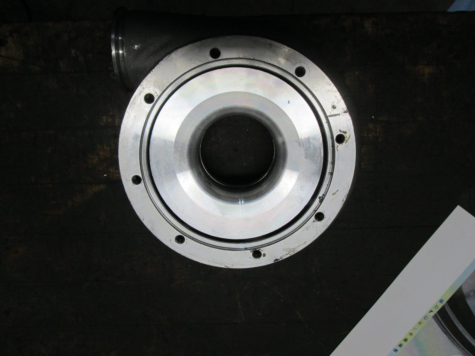
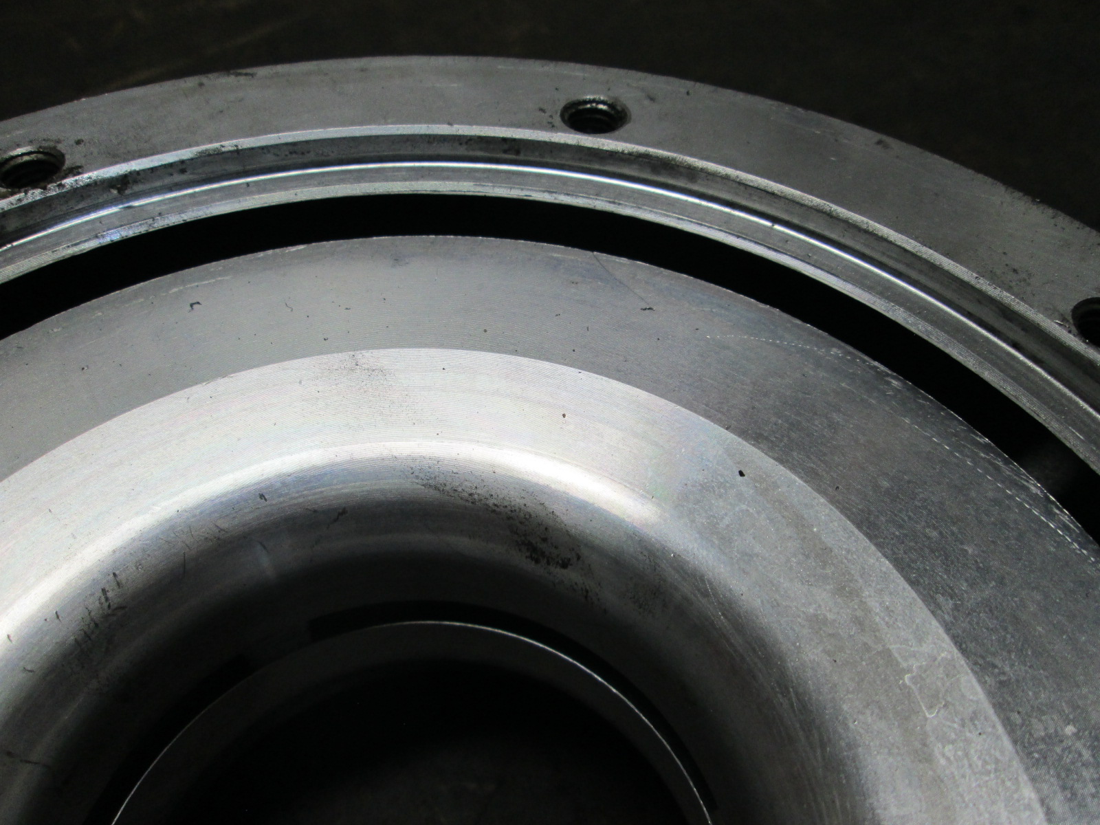
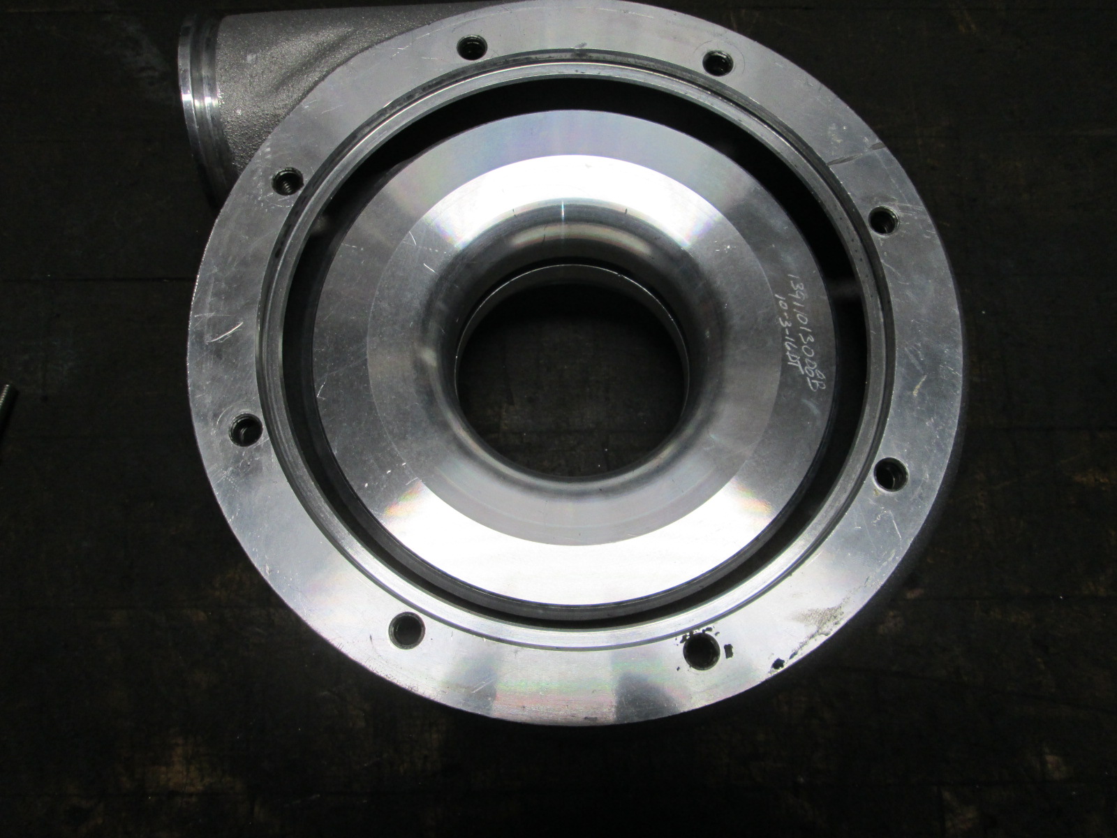
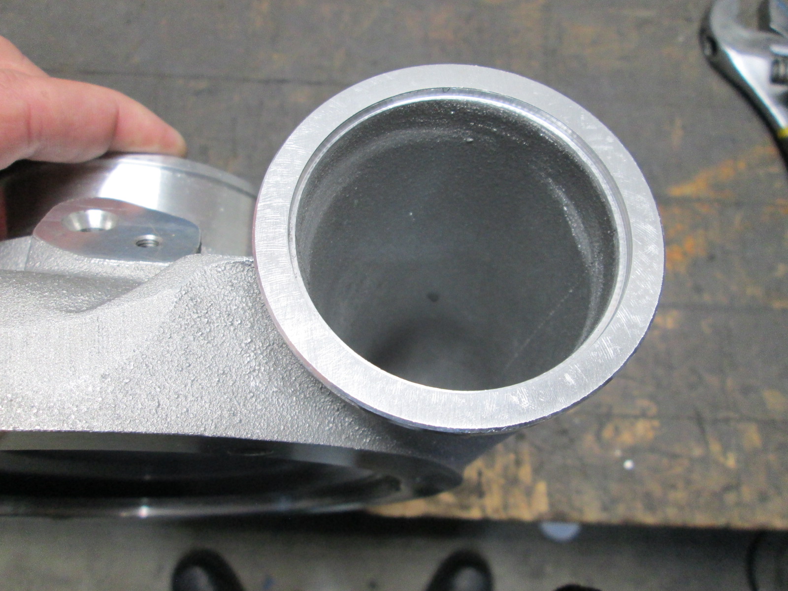
The 369SXE is said to be better suited for small cube, high boost applications. General internet theory is that it is due to the much smaller gap in the housing for the air off the wheel to exit. The gap is quite small being 0.225 to 0.25" and the older versions were about twice as large from other pictures.
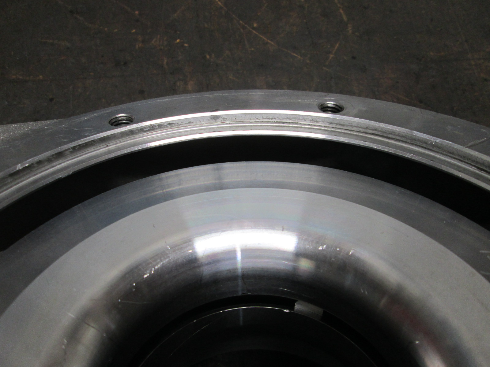
So while everyone thinks the main issue with the 369sxe is the gap, I haven't ever seen someone try to modify it. So why not... went ahead and opened that section of the compressor housing up to .350".
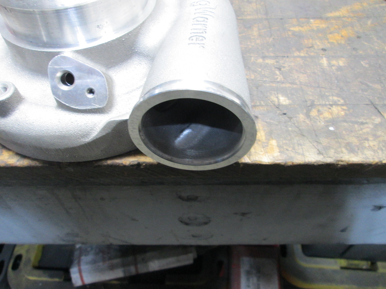
The cover also had the hose barb outlet section cut off and machined flat with a pilot bore to accept a V-band:
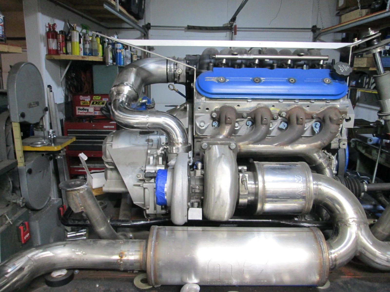
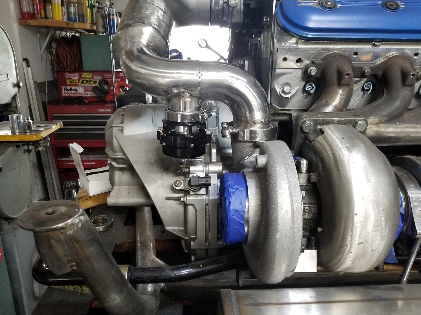
Last thing I did this weekend was tack together the cold (non-I/C = warm) side. V-band off the compressor, silicone coupler at the TB. There is a honeycomb airflow straightener about 1.5" after the diameter transition. The LS7 MAF will be after it and before the bend.
[This message has been edited by fieroguru (edited 05-01-2022).]
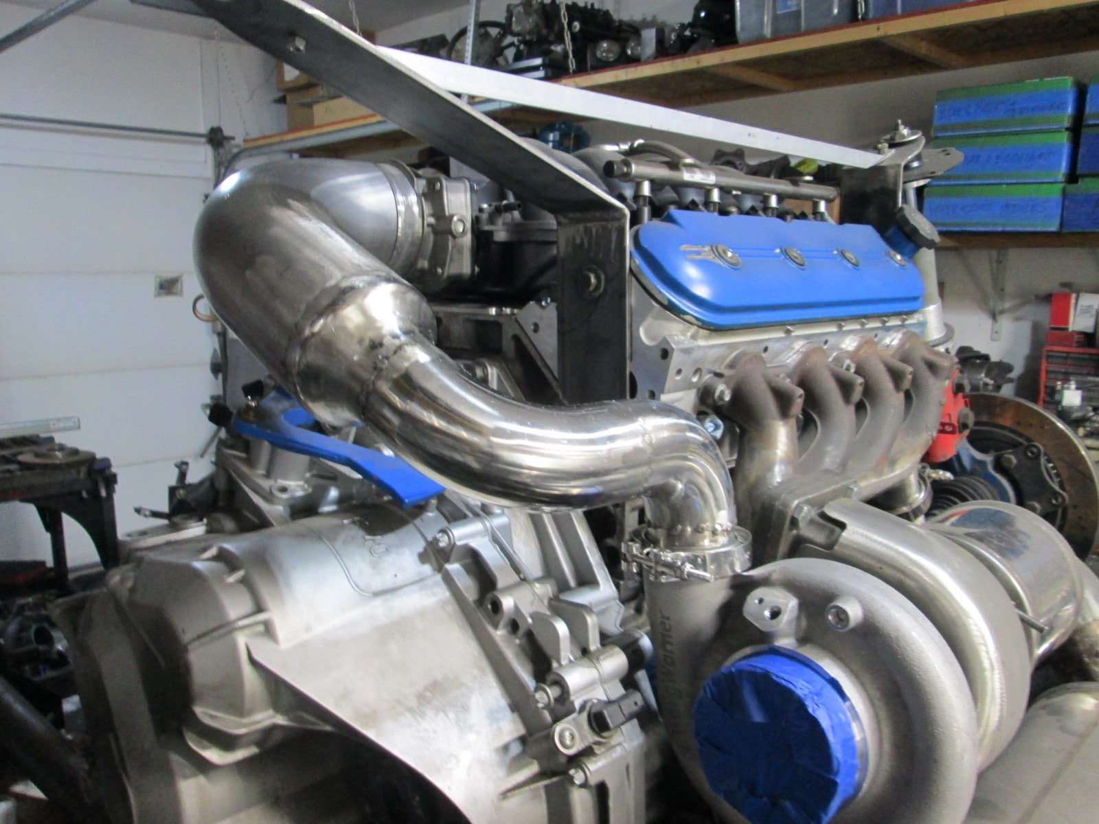
That's really impressive work, I really like how you've managed to install everything so well/proper in such tight spots.. looks amazing.
Thanks! Keeping things organized, compact and hidden is an obsession of mine. Lots of thought, trial, error and rework is involved to get to the final elegant solution.
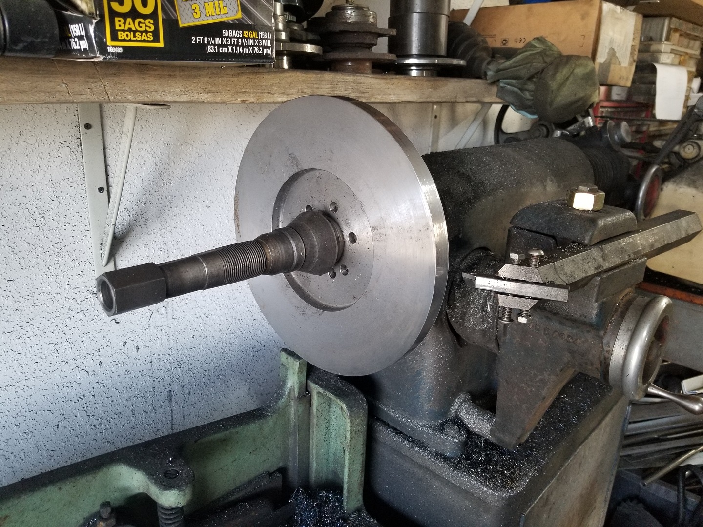
I have been working on adapting an off-the-shelf twin disc clutch to the LS4/F40 and to the point I need to actually check the depth and clearance to the differential bulge in the bellhousing. It will require some modifications to my existing aluminum flywheel, but I don't want to modify it until I know it fits... So I pulled the billet steel 168 tooth LS1 flywheel out from under the work bench and turned it down on my brake lathe.
It is now the same OD as my aluminum flywheel and a smaller OD than all the prior pressure plate bolt patterns. The next step is to drill the pressure plate bolt pattern.
I also started working to finalize the exhaust discharge from the wastegate. Disconnected the wastegate muffler to move it closer to the wastegate and make it parallel to the floor as well as to the muffler. Still pondering if I will connect it to the full exhaust of just run it down and dump it at the bottom of the cradle. I need to get some more 2" 16ga stainless mandrel bends.
[This message has been edited by fieroguru (edited 05-08-2022).]
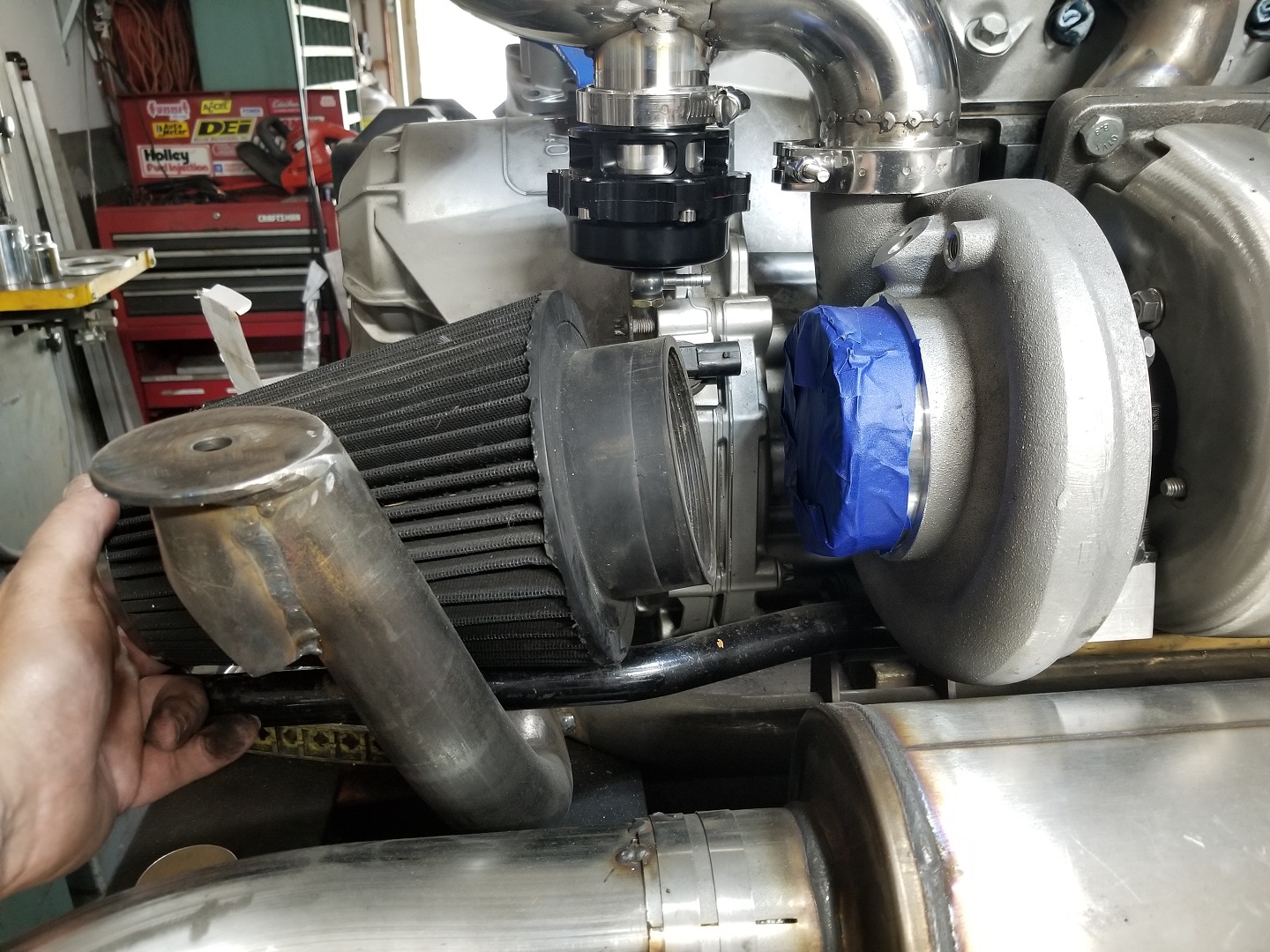
Only had about 1/2 day to work on the swap this weekend so focused on the cold side and waste gate plumbing. Removed about 2" of the 2 1/2" tube before the transition to 4" and added about 2" more of the 4" diameter tube after the transition. The longer this section of tube is before the bend the happier the LS7 MAF will be. Also mounted the 50mm blowoff valve and figured out the rough placement for the air filter.
Finished mocking up the wastegate exhaust dump. I decided to just dump it under the cradle vs. routing it into the main exhaust.
Still need to fit the resonator tube, fabricate all the support brackets for the exhaust, finish up the work with the heat shields for the hot side then lots of finish welding on the exhaust...
[This message has been edited by fieroguru (edited 05-15-2022).]
I hadn't given much thought to the exhaust getting the sway bar hot enough to impact its heat treatment. I might just add a couple more heat shields to keep it warm vs. hot
I hadn't given much thought to the exhaust getting the sway bar hot enough to impact its heat treatment. I might just add a couple more heat shields to keep it warm vs. hot
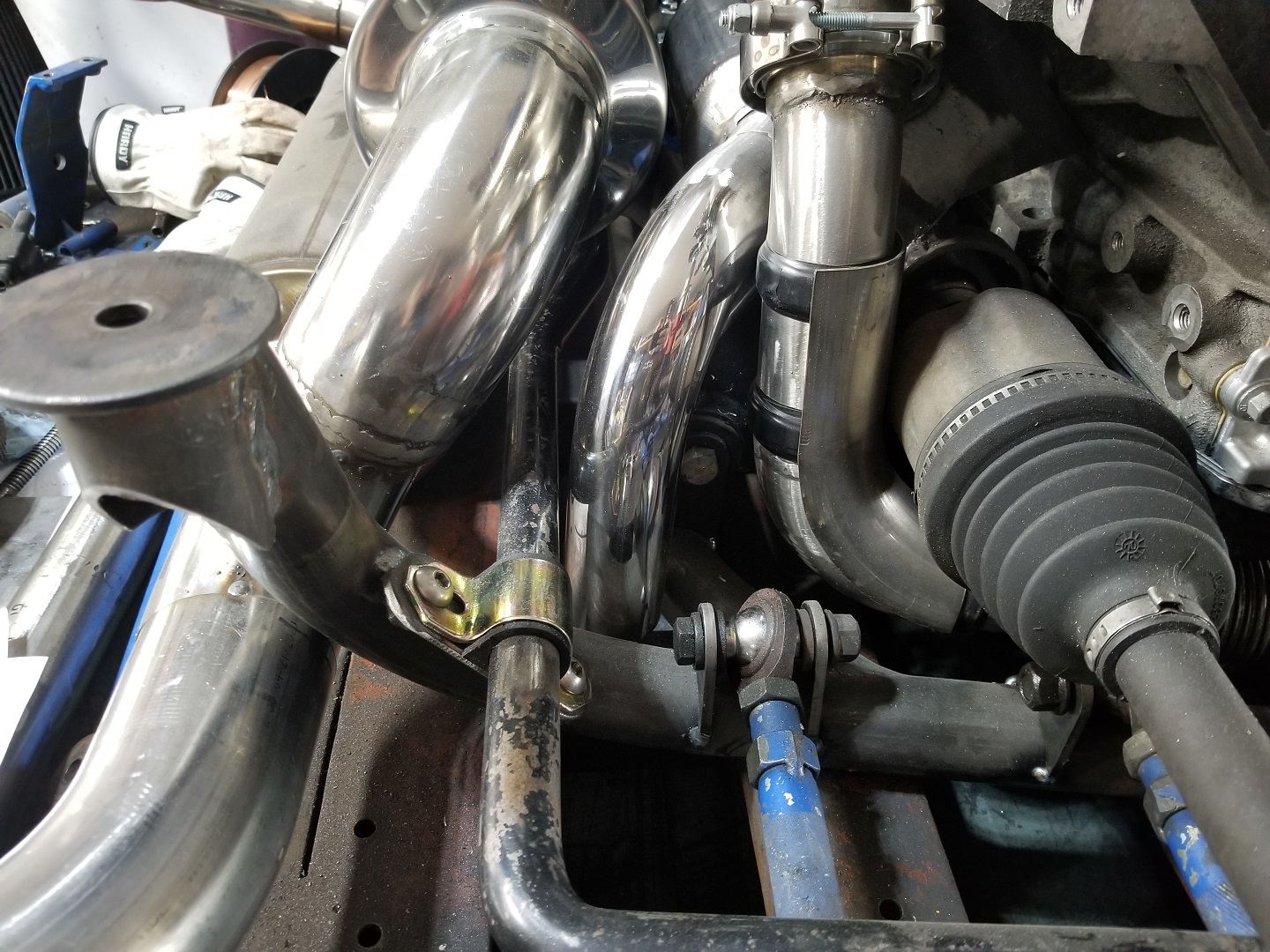
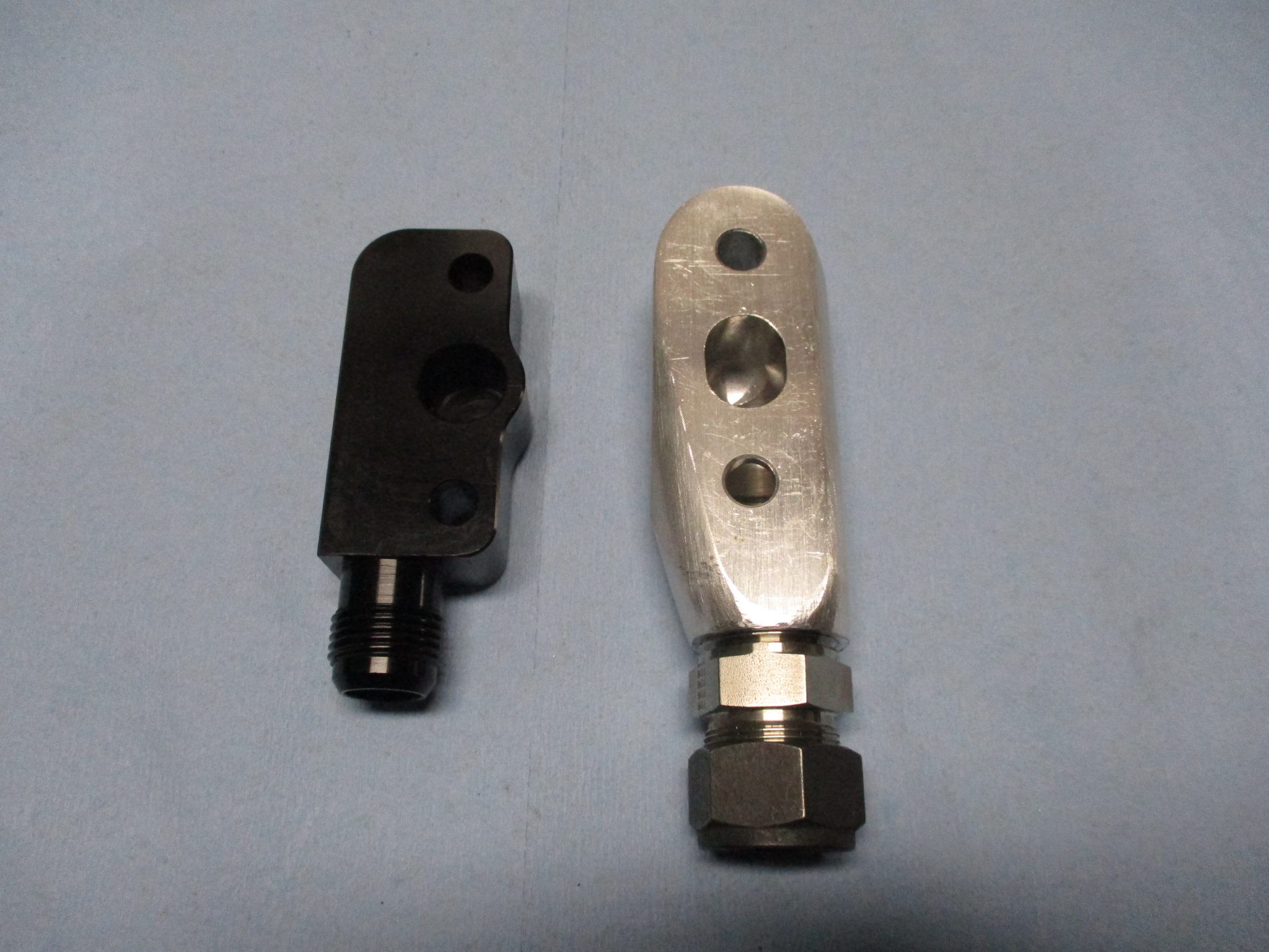
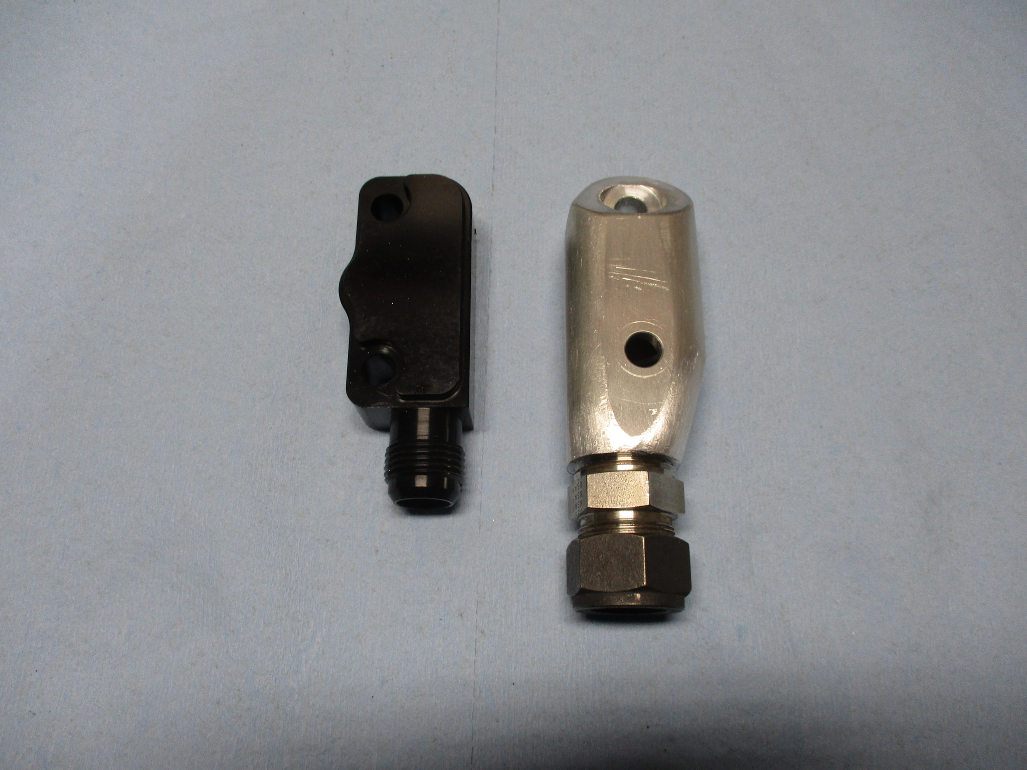
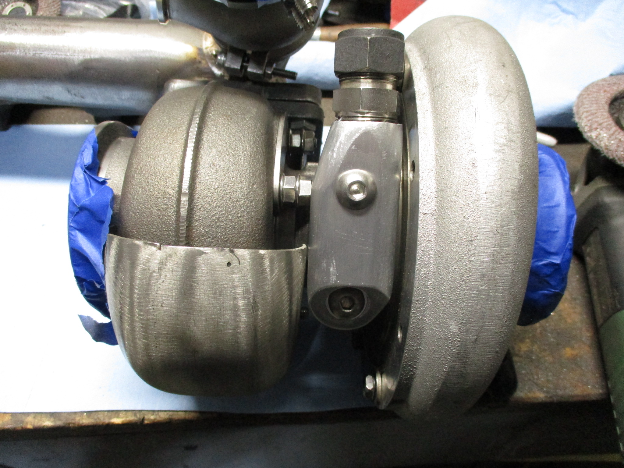
Since I won't have much time to play with the car this weekend, I just played around with the turbo oil drain fitting. I had picked up some off the shelf fittings to try, but they interfere with the heat shield and the internal passages are smaller... so I will stick with the one I made that uses a 3/4" drain tube and clears everything. Then I focused on making it look less blocky, but not 100% complete at this point.