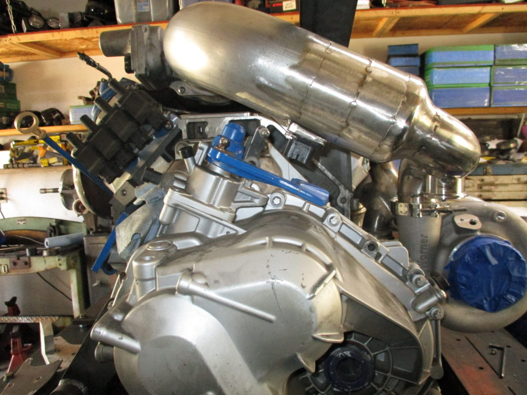
Locked down the MAF location. It is about 1" past the honeycomb insert and the connector harness will clear the range of motion of the shifter arm. Once I got it mocked up, I noticed that the intake tube is parallel with the shifter arm... didn't plan it that way, but a very nice coincidence!
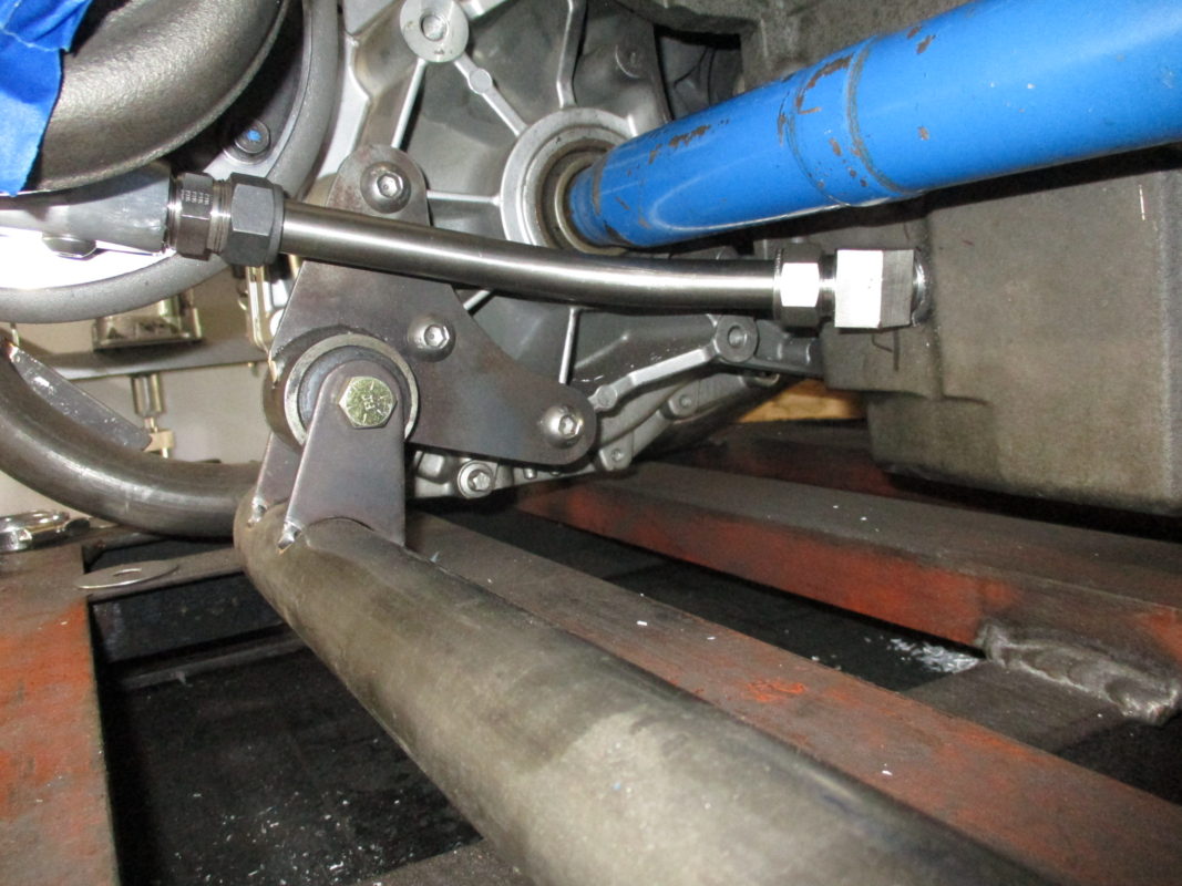
Put the finishing touches to the oil drain line (3/4" .028" tube).
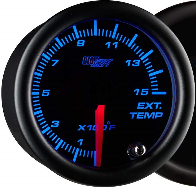
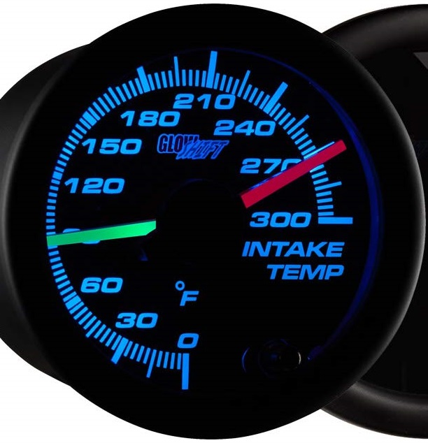
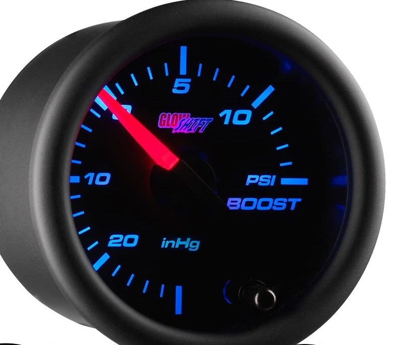
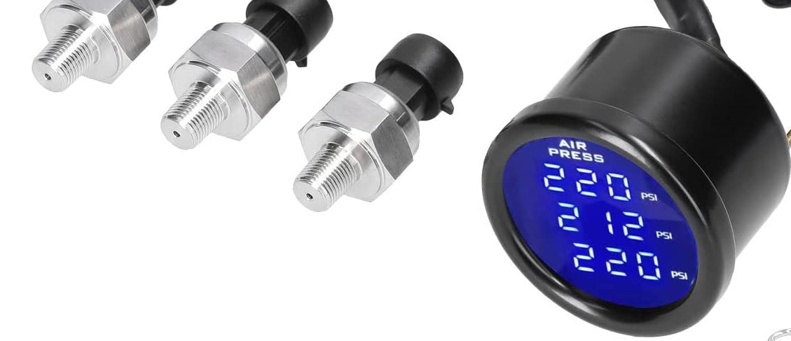
Started thinking about all the boost related plumbing and sensors... Since this is my first turbo and it is non-intercooled, I wanted to monitor some key parameters: EGT pre turbo, Air temp pre/post turbo, and boost pressure. Here are the gauges I picked up so I can monitor those items:
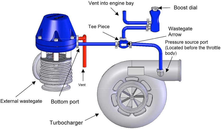
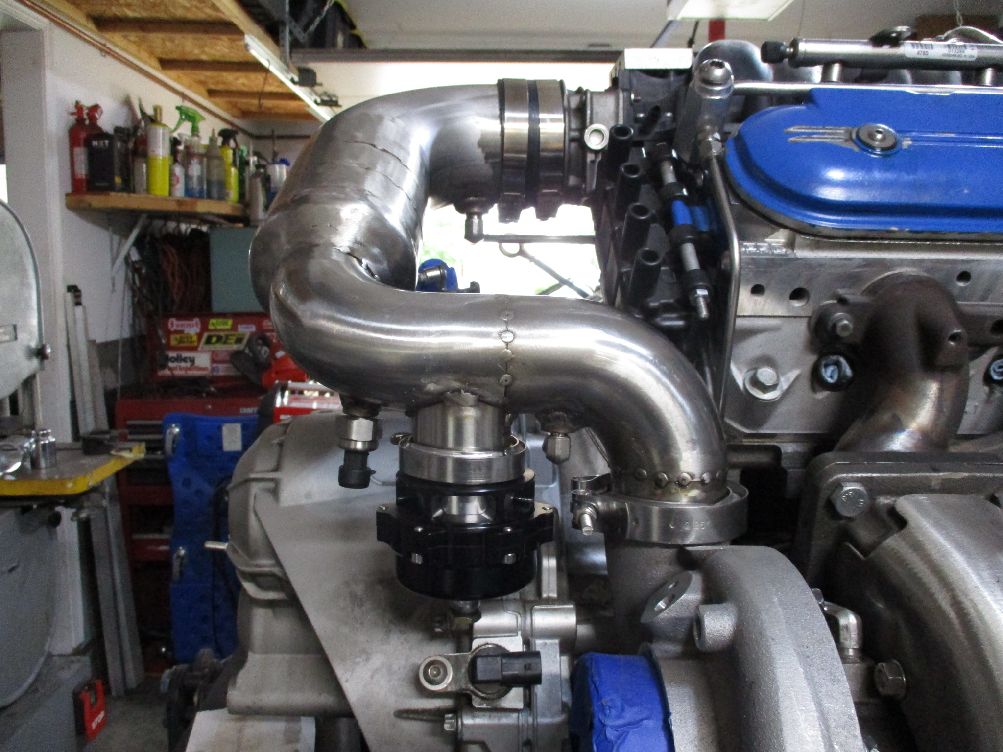
For boost control, I am going to keep it simple to start with. Manual engine bay mounted adjustable boost control valve plumbed like this:
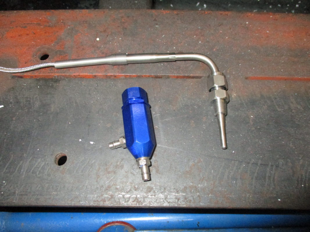
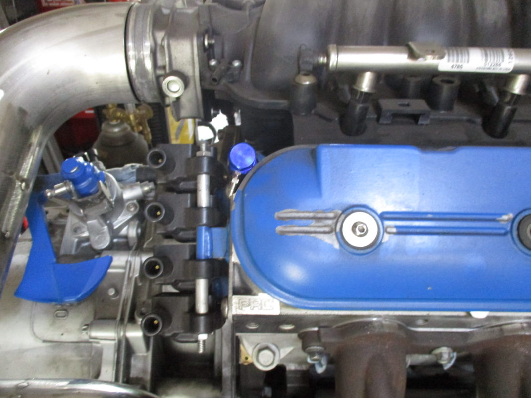
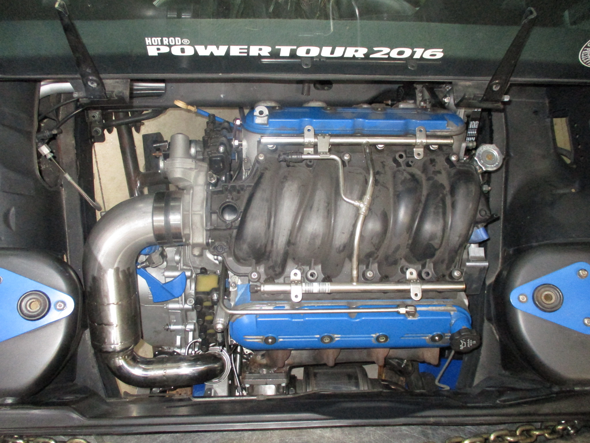
Here is the manual boost controller (and the EGT probe). Thinking of mounting it up by the valve cover and coils to keep the plumbing short (and hidden), but far enough from the turbo to not be 200+ degrees for when I want to adjust it.
[This message has been edited by fieroguru (edited 05-29-2022).]
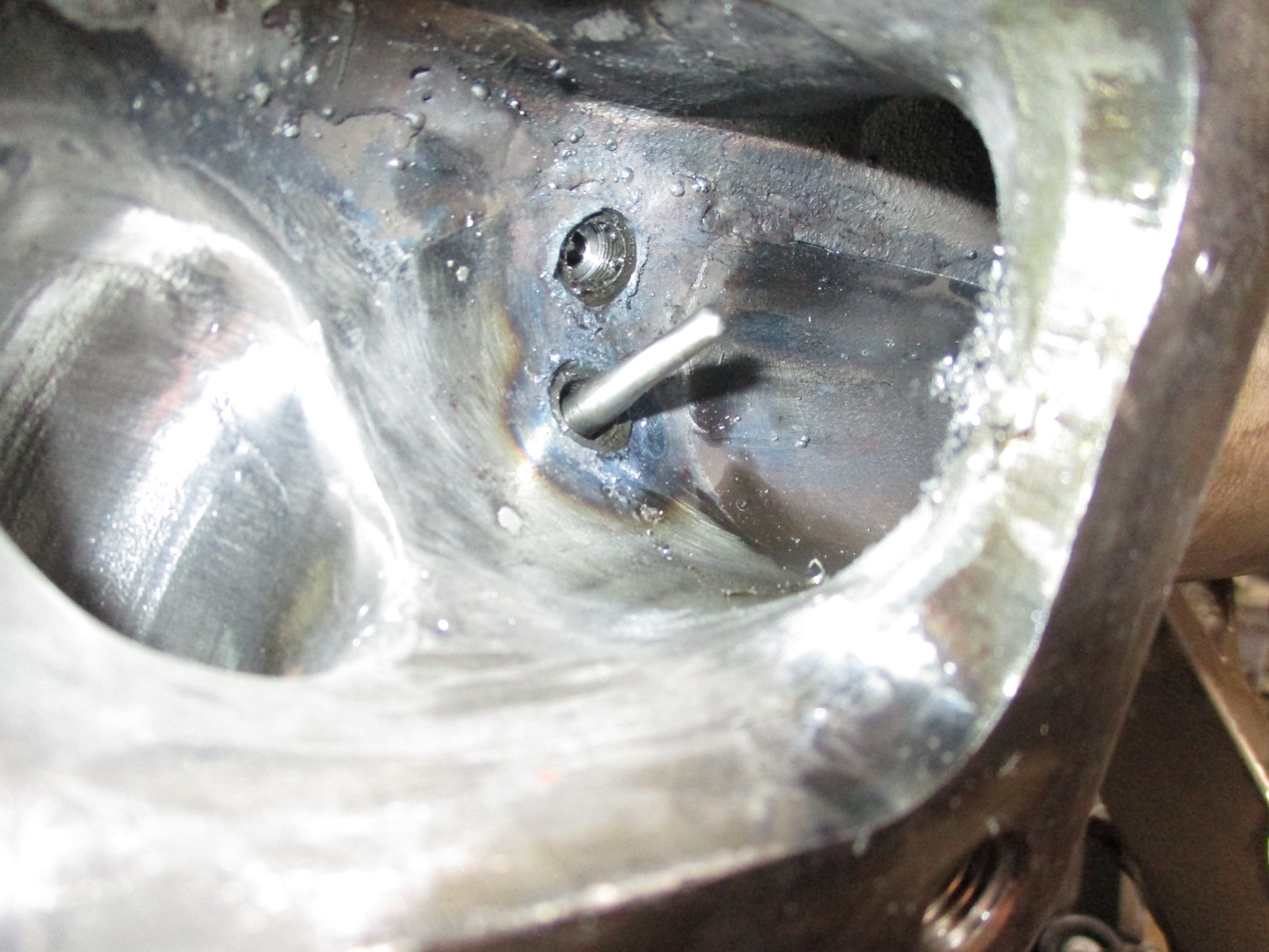
Started working on some of the more tedious aspects of the turbo setup... oil feed, reference lines, and data sensors.
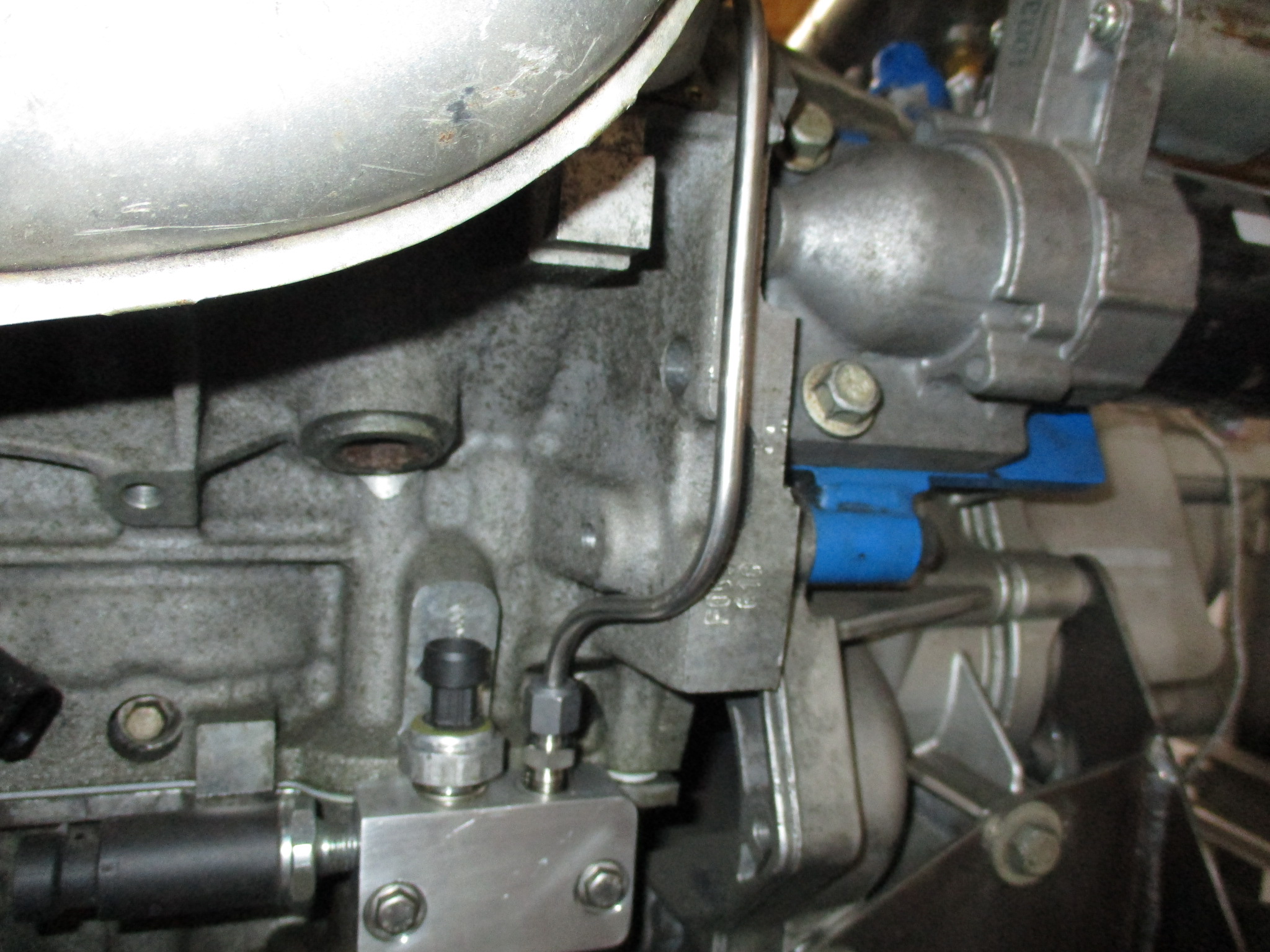
Here is the start of the oil feed line off the multi-port oil bypass:
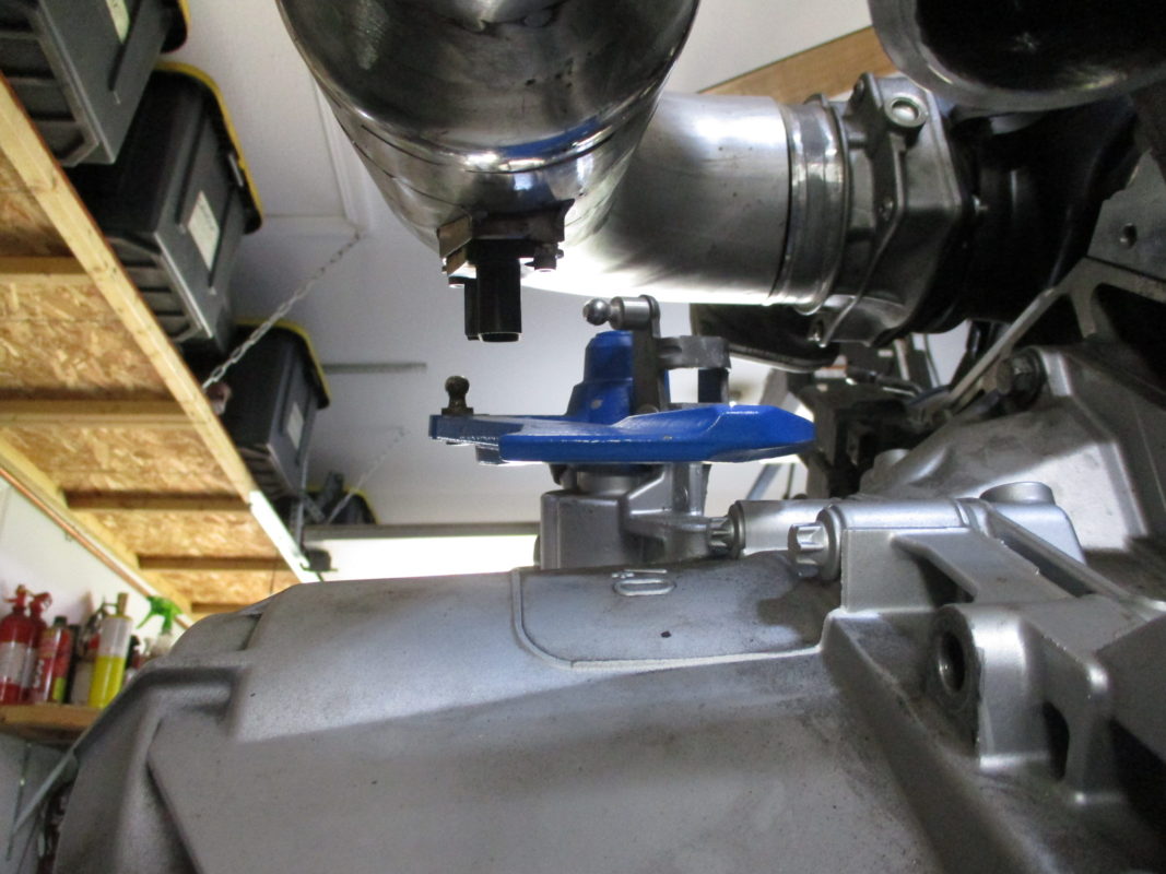
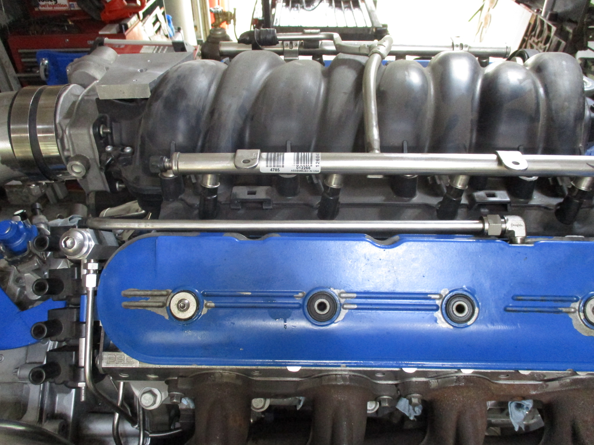
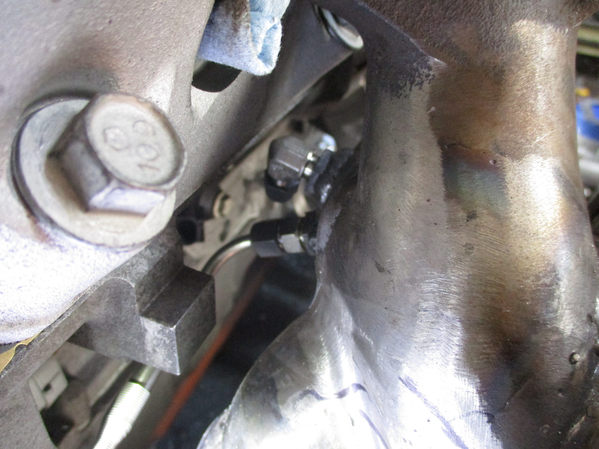
Here you can see the oil line going over the bellhousing. Also visible is the PCV hard line connection to the air intake tube (filtered & metered air)
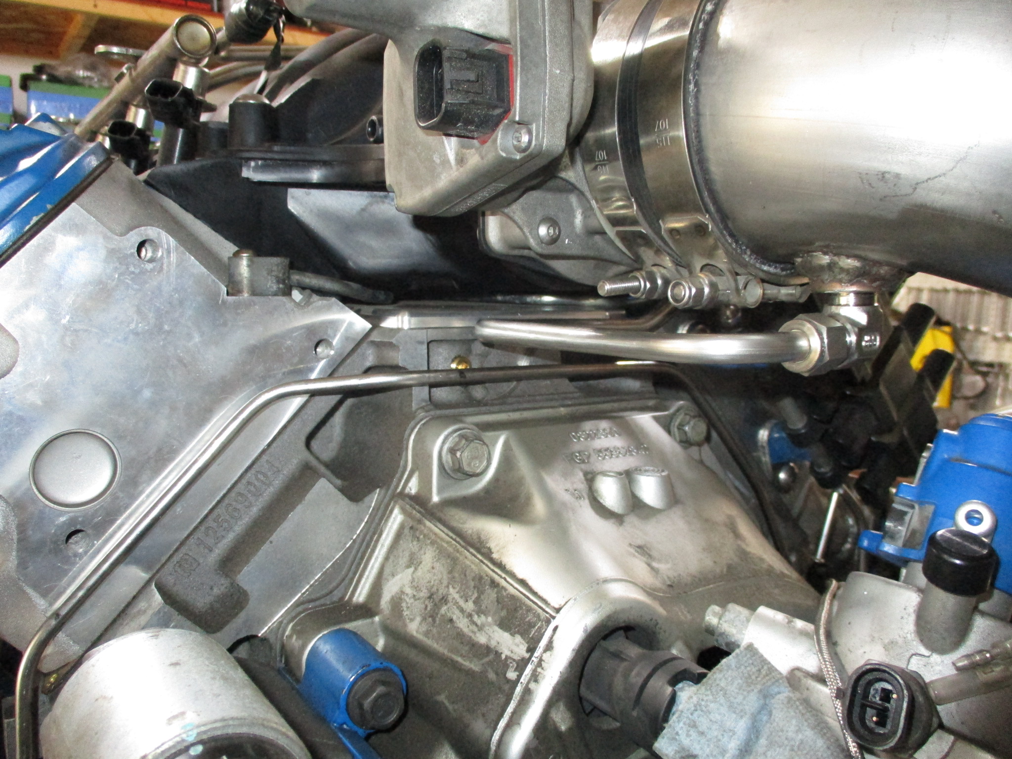
This is the end of the oil feed line.
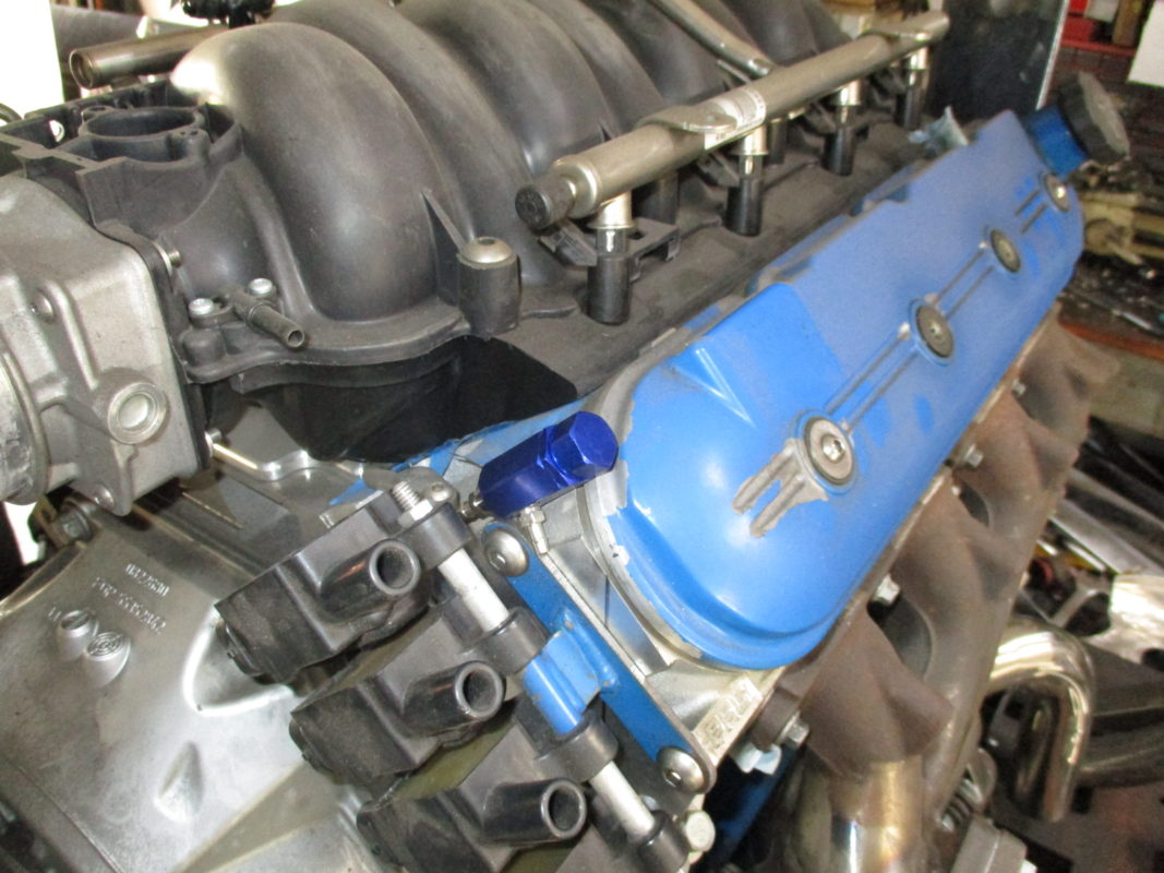
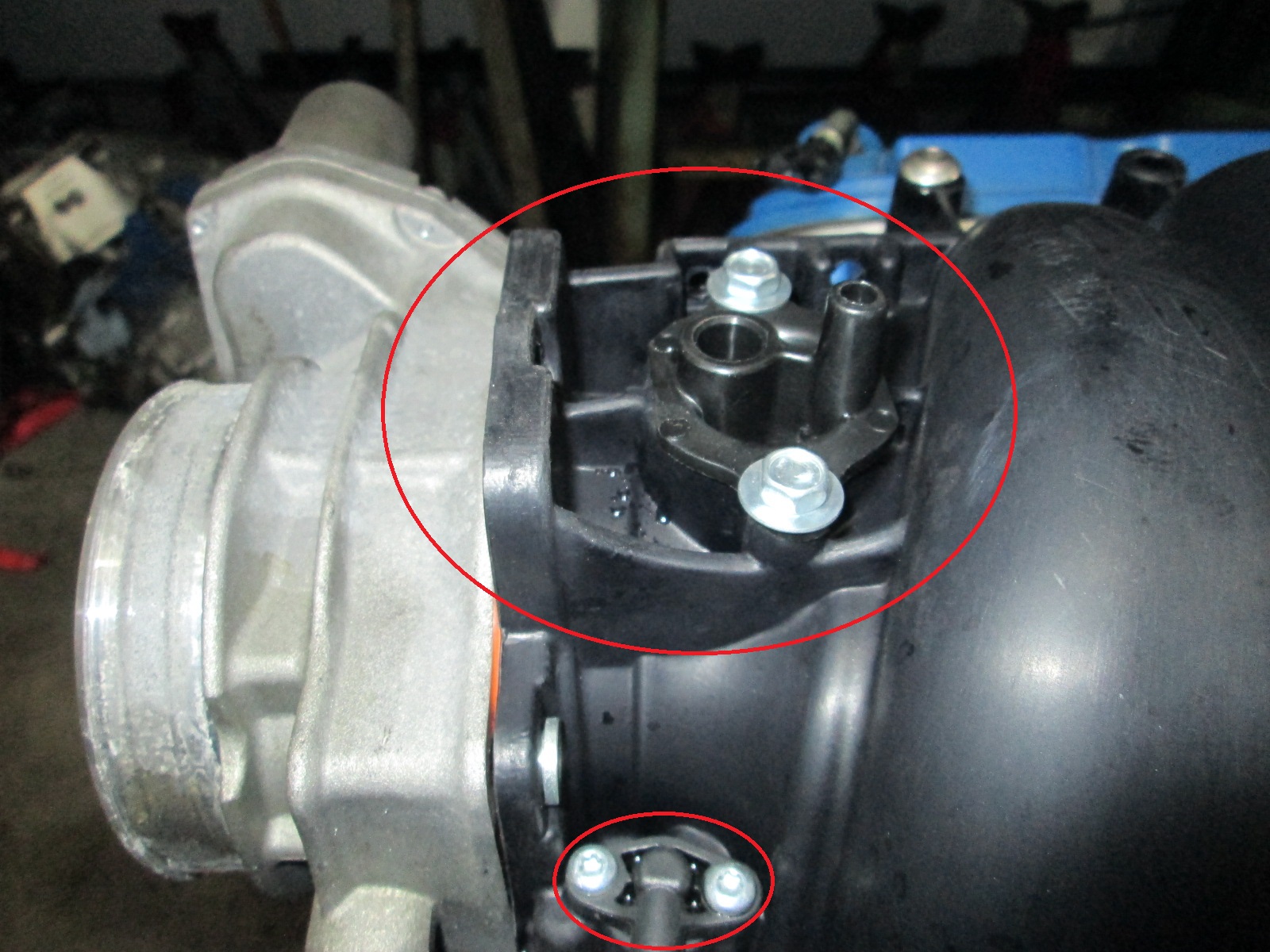
This picture has the connection of the PCV hard line to the valve cover. Also visible is the new adjustable boost knob (button head). I didn't like how small the blue one was and it wouldn't accept the hard lines, so I took the spring and ball and made a new housing from aluminum hex.
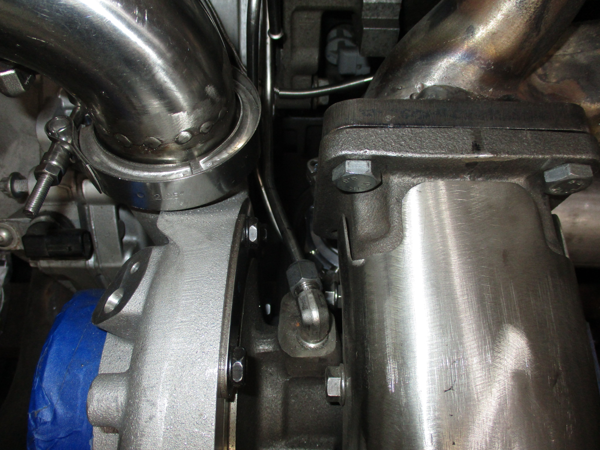
The warm side had a sensor boss (pressure), temp boss (not seen - it is downstream of MAF), and boss for the waste gate hard line.
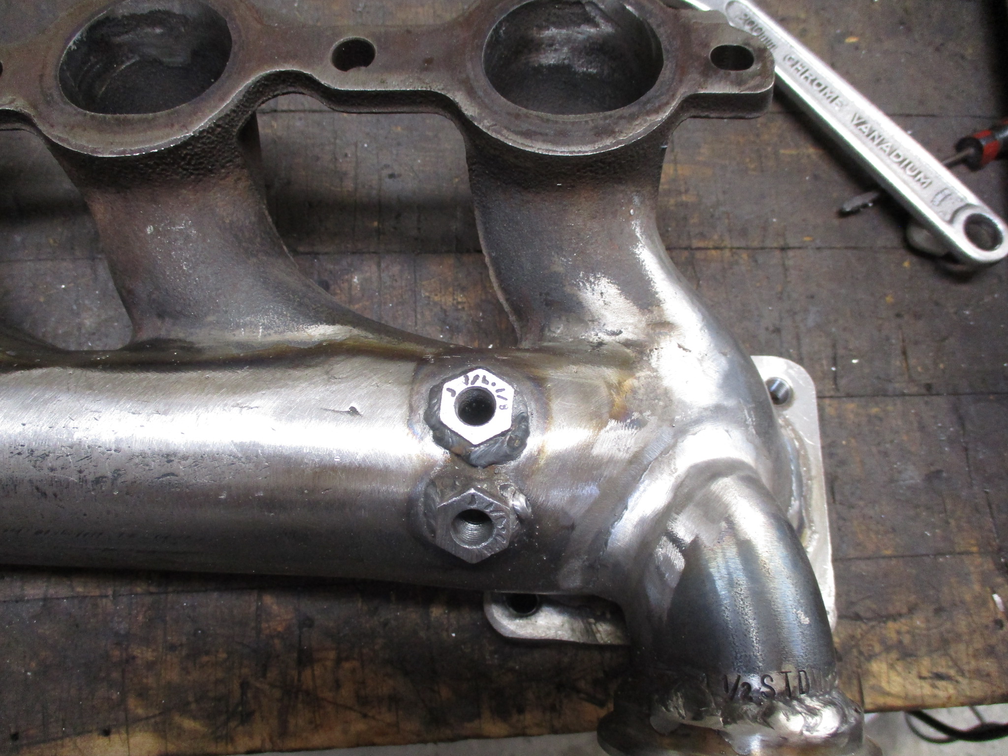
I also welded some bosses onto the turbo manifold back side for the EGT sensor and a hard line to a pressure sensor.
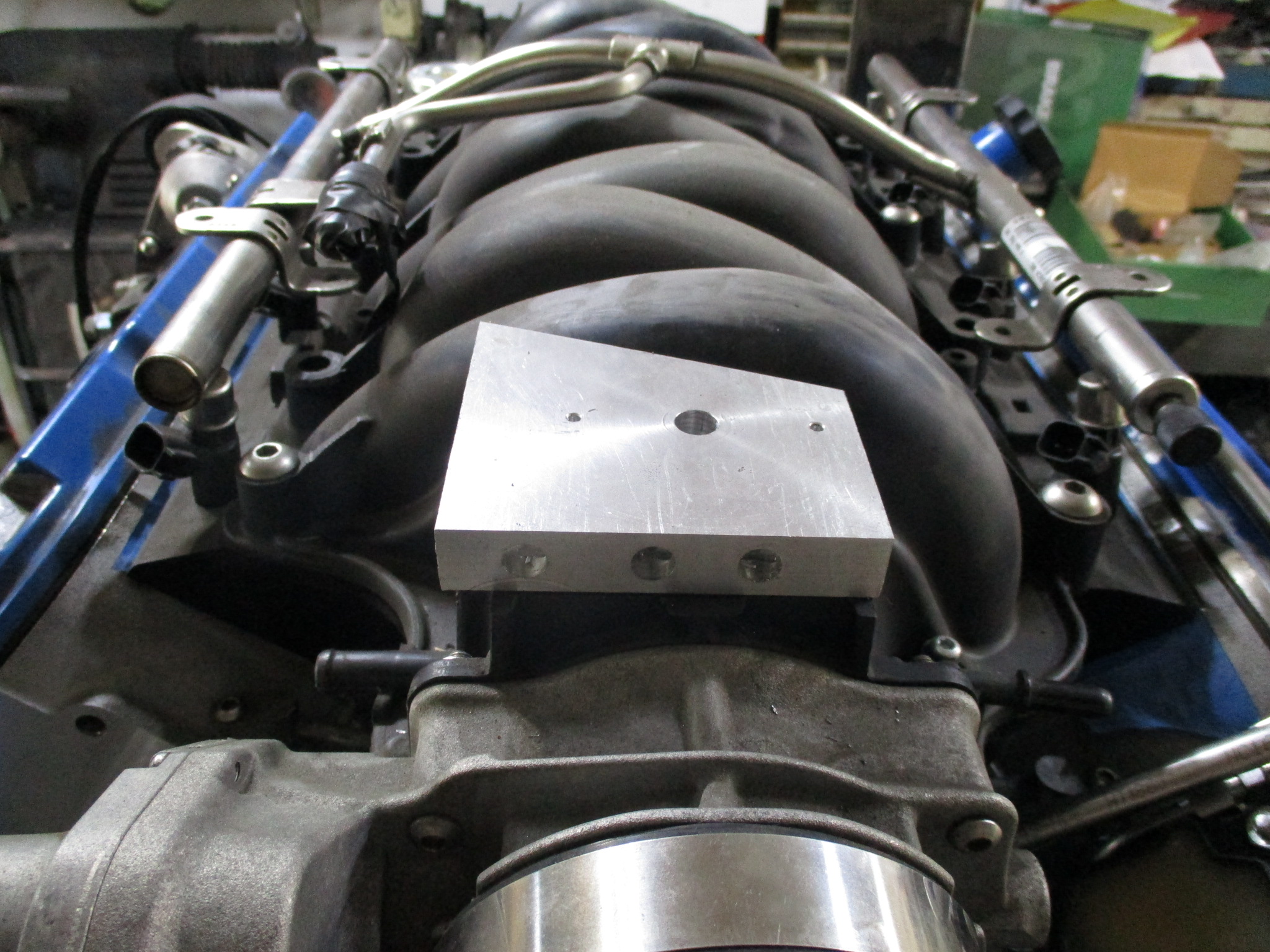
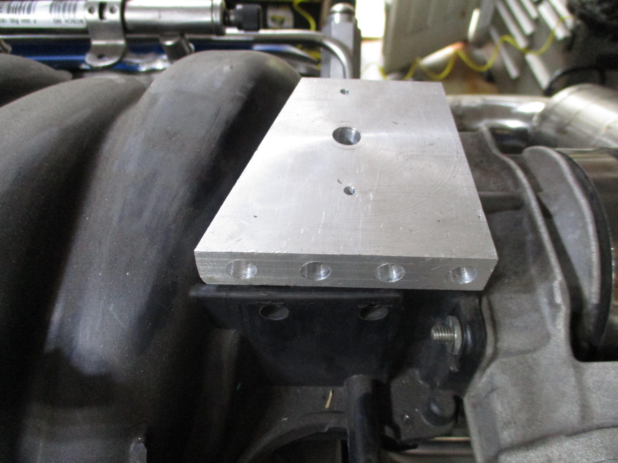
The intake manifold also has an ugly hole right behind throttle body and there are several needed reference lines from the manifold (BOV, PCV (dirty) MAF, vac tank for cutout). To address both, I started making vacuum/boost manifold that will cover the hole in the intake as well. It has a machined boss on the bottom side with an o-ring seal for the intake hole.
I want to get a feel for the pressure ratio of the pre/post turbo as well the exhaust back pressure with an without the cutout open. This 3 in one sensor will give be some visual data w/o needing to actual log it. It will be like the dual temp gauge for the pre/post compressor temp delta as well.
The goal is to have this swap at first glance look like the previous naturally aspirated swap with very little exposed wiring, hoses, hard lines. That will be a challenge as there are close to 20 lines and sensors added just for the turbo setup. A few weeks ago I added a page to my wiring file for the swap and detailed out all the extra lines and sensors. For the sensors I decided on what really needed to be logged and what only needed some basic visibility to (gauge only data). This is what lead me to find the dual temp gauge and the triple pressure gauge.
It is one of those things I will have to evaluate to know for sure. Worse case, I have to add a scavenging pump.
To help maximize the drain performance, it is hard line vs. rubber, 3/4" vs. 5/8 (or smaller), is positioned in the portion of the oil pan right behind the factory opening - which means the oil would have to slosh a bit to flow back through the drain, and most WOT runs should be limited 10 to 11 seconds.
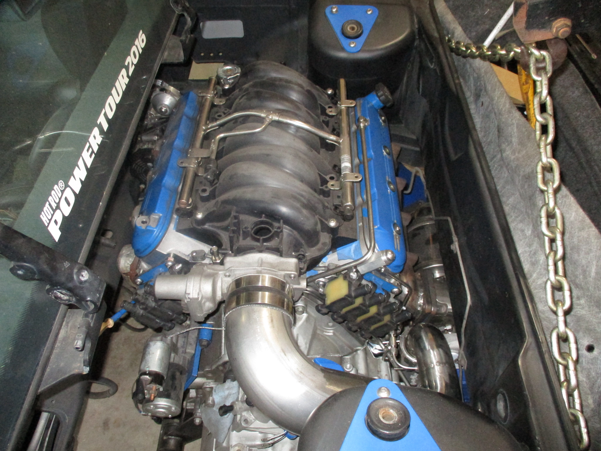
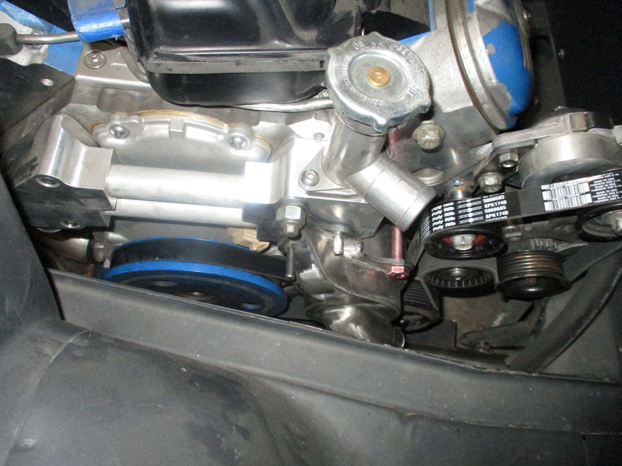
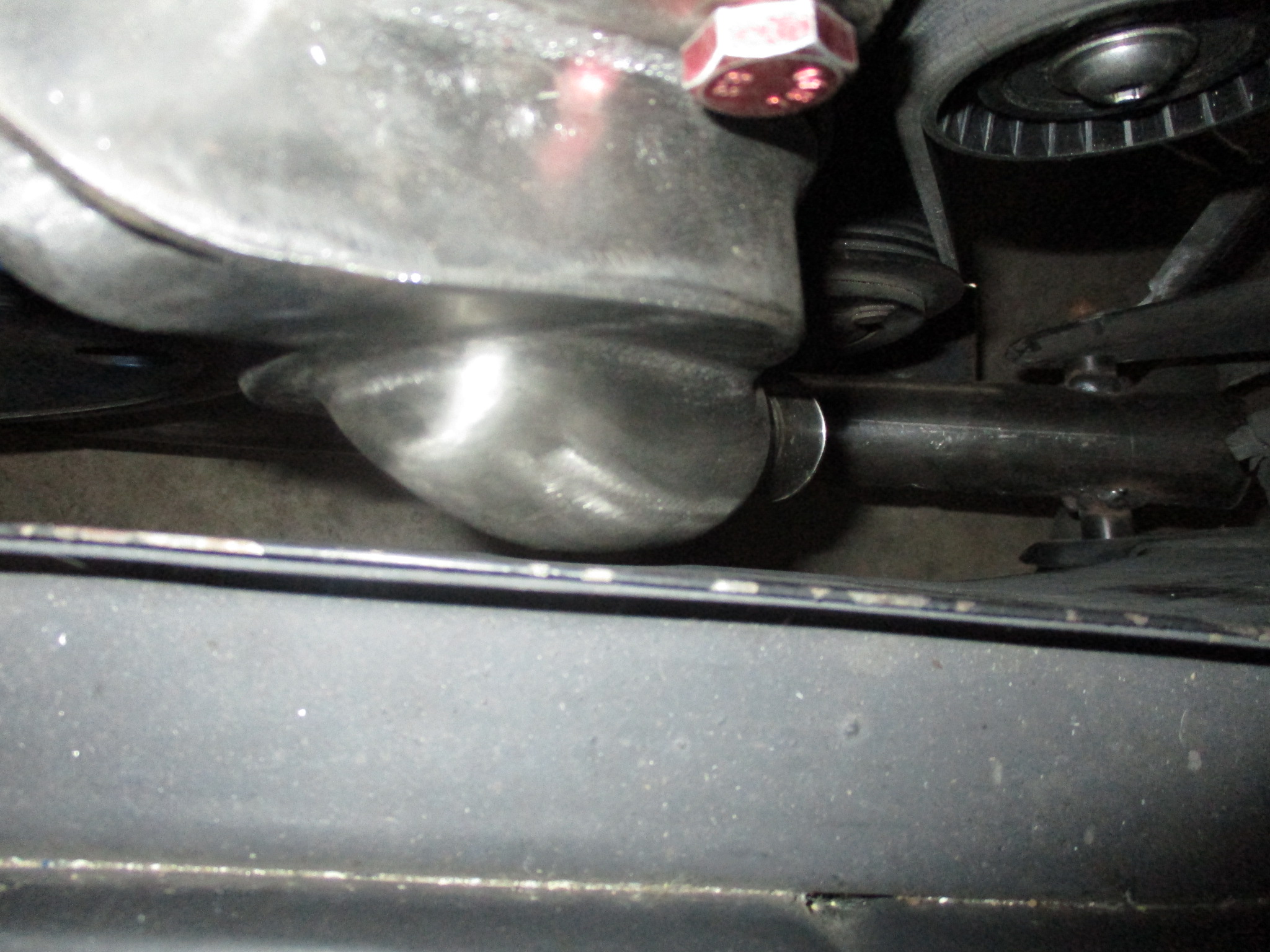
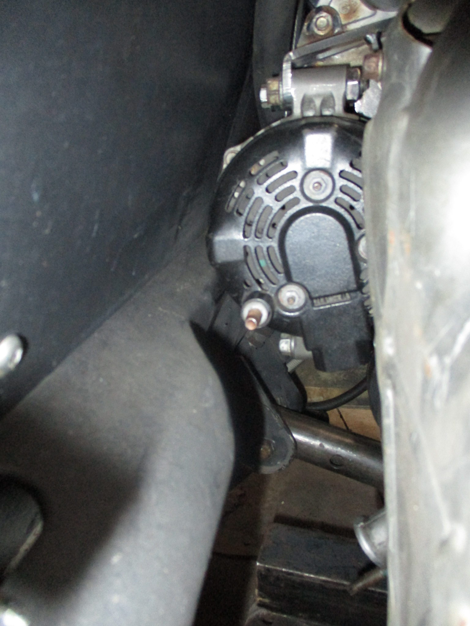
I have finally reached the end of the major fabrication for the engine/transmission/turbo and cradle. Finished up the alternator and ac brackets and put everything back in the car for one of the last (but probably not the last test fit). The alternator clears the cross support by about 1/4" and the mechanical water pump clears the side frame by about 0.1". Overall I am pretty pleased and looking forward to finishing up all the final welding on the cradle and exhaust and moving onto the wiring and plumbing.
I see you have no intercooler, are you planning on water/meth injection? a while ago "Engine Masters" on motortrend (or maybe it was Richard Holdner) ran a comparison of water/meth vs intercooling, the biggest issue they ran into was that it appeared the water meth distribution was very poor in their LS barrel ram intake. if I remember right, they installed probes in the intake tract to monitor performance. some people have run pre turbo water injection, I suspect the distribution would be much better, however I imagine a downstream MAF would hate that.
------------------ "I am not what you so glibly call to be a civilized man. I have broken with society for reasons which I alone am able to appreciate. I am therefore not subject to it's stupid laws, and I ask you to never allude to them in my presence again."
I invited Lou Dias to trash me in my own thread, he refused. sorry. if he trashes your thread going after me. I tried.
Originally posted by ericjon262: I see you have no intercooler, are you planning on water/meth injection?
No plans for water/meth, just E85. Boost will likely stay in single digits to reach my initial power goals, so I am not concerned with excessively high intake air temps at the moment.
Looking great as always. Any news on the LS4 water manifolds? I looked back and last I saw was a small batch last year, but sounded like there were some quality issues you didn't like.
Looking great as always. Any news on the LS4 water manifolds? I looked back and last I saw was a small batch last year, but sounded like there were some quality issues you didn't like.
That is still the case. I purchased a CNC mill for delivery in December and the long term plan is to bring all machining operations back in house. I probably won't dedicate time to fine tuning the mill until I get my car back on the road. It has been down for almost 3 years now...
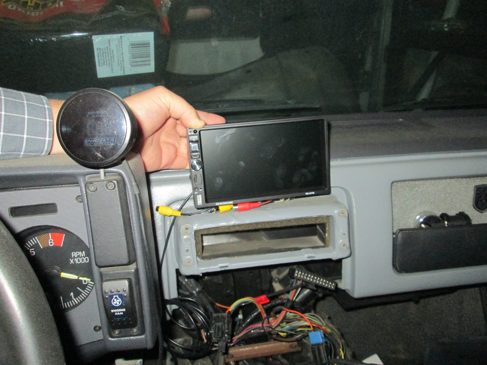
While I have the Fiero pulled away from the wall, I decided to play around with the stereo setup some...
Lets recap what the current plan is: Low profile 7" GPS/NAV/Rear CameraAndroid/Blue Tooth etc.. head unit to be mounted where the aux gauges normally are.
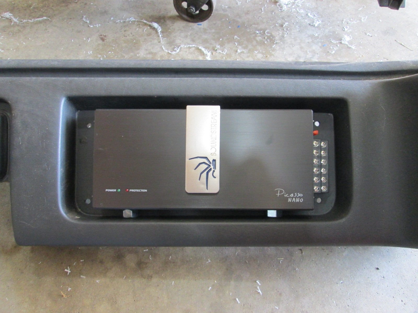
5 channel soundsteam nano amp mounted in the dash cubby.
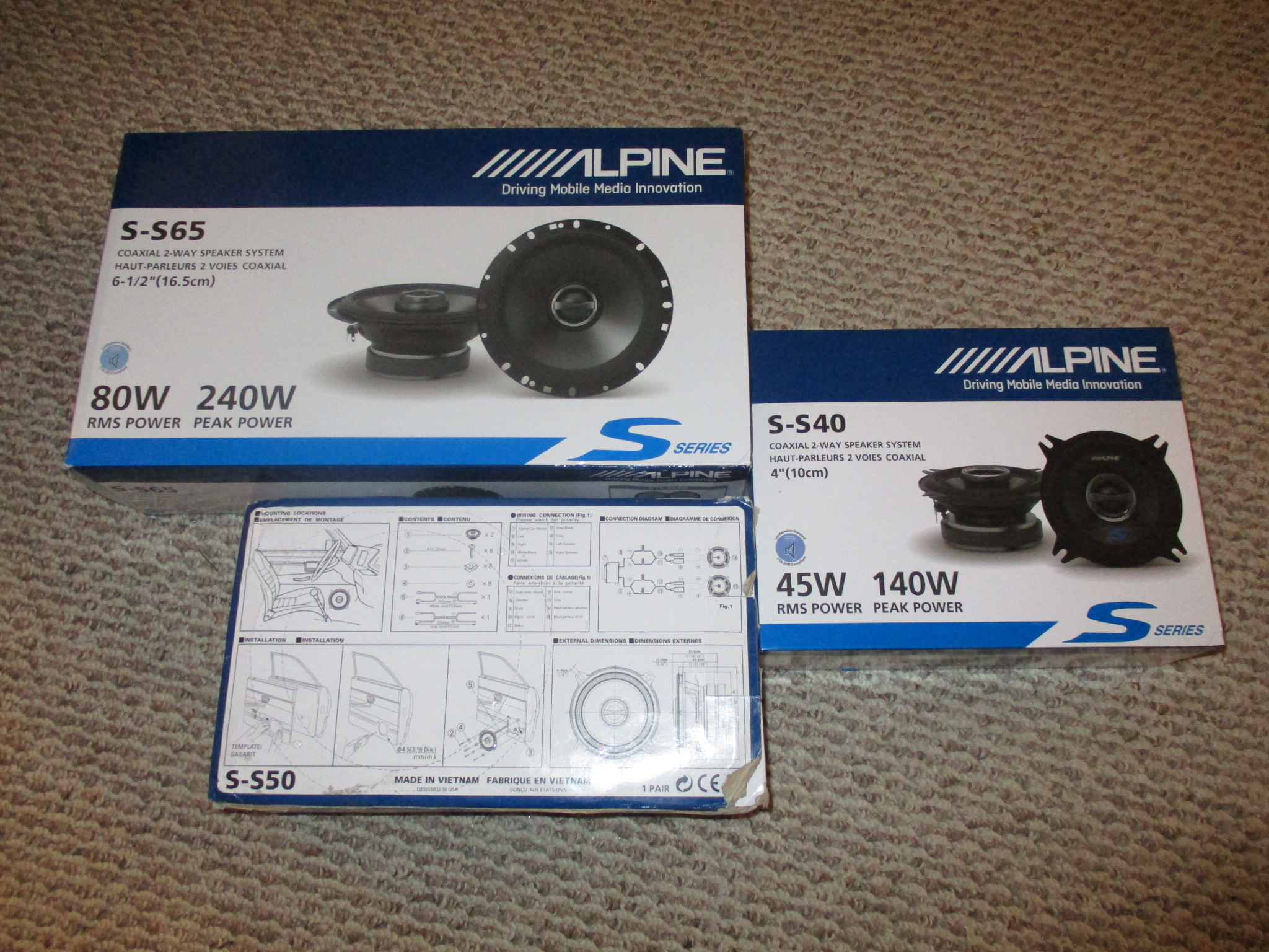
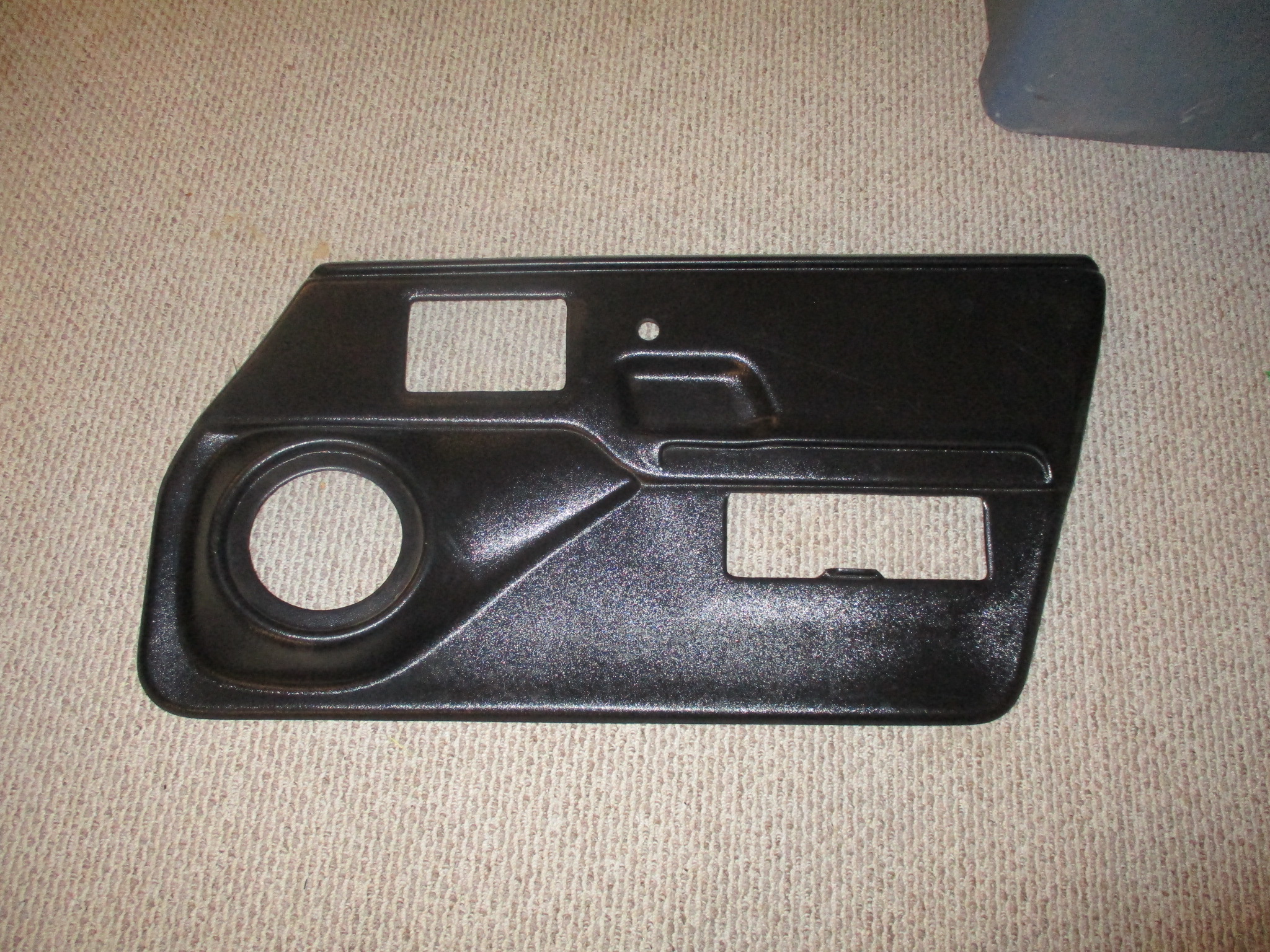
For the speakers, I went a little nostalgic and chose Alpine: 4" for the B pillars 5 1/4" for the Dash 6 1/2" for the Fiero Store door panels.
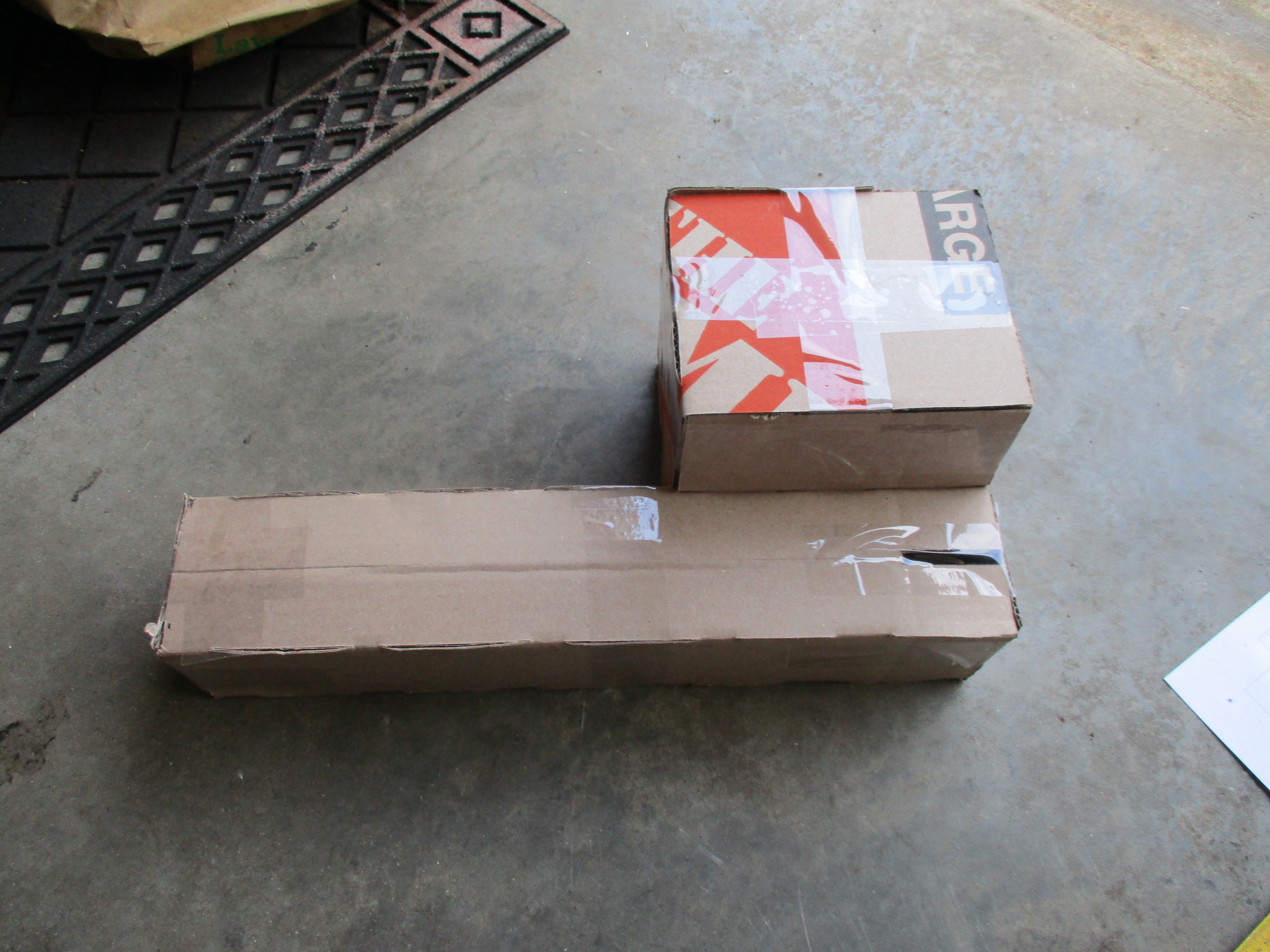
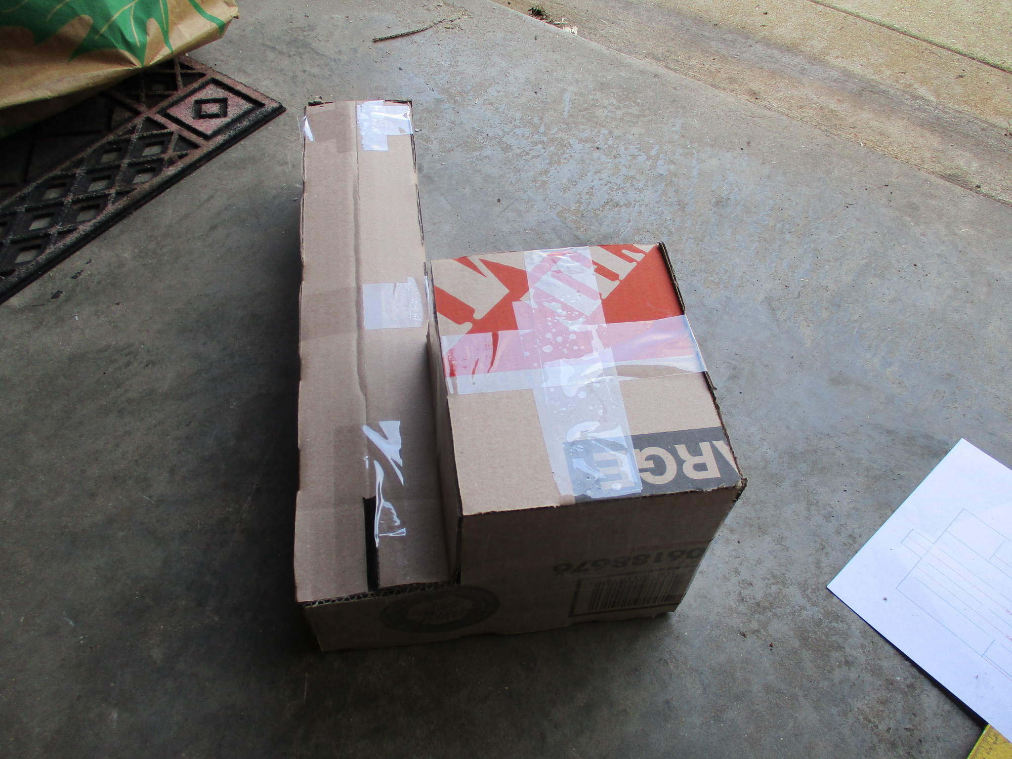
Then it came to the subwoofer... the under dash box that Alex4mula made would allow an 8" sub. I made a mock up from card board (1 single piece, lots of cuts, bend slices and tape). I took out the stock sub housing with the modified tang bang and started to test fit. I still need to remove a couple of brackets to get it fully into place.
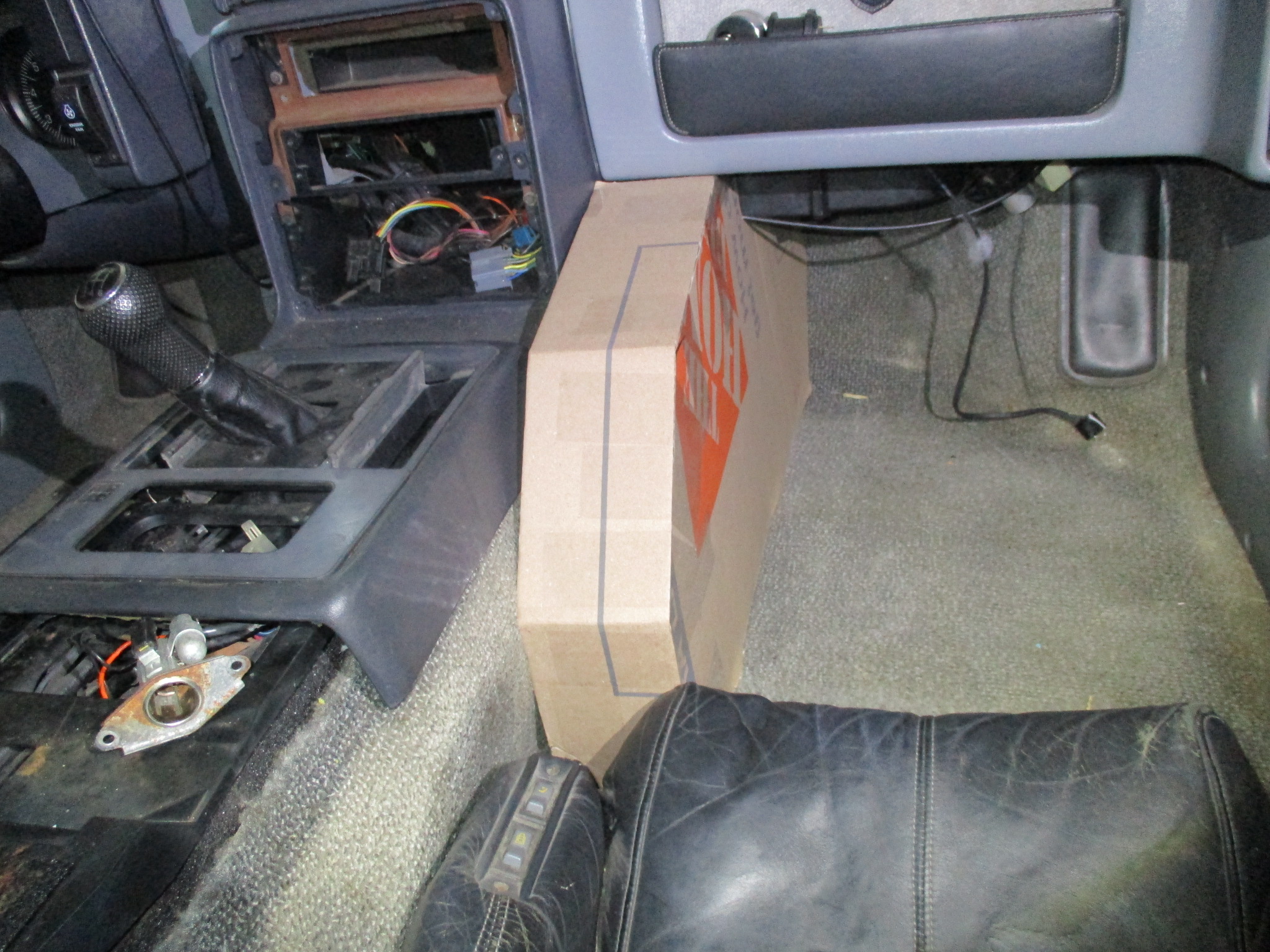
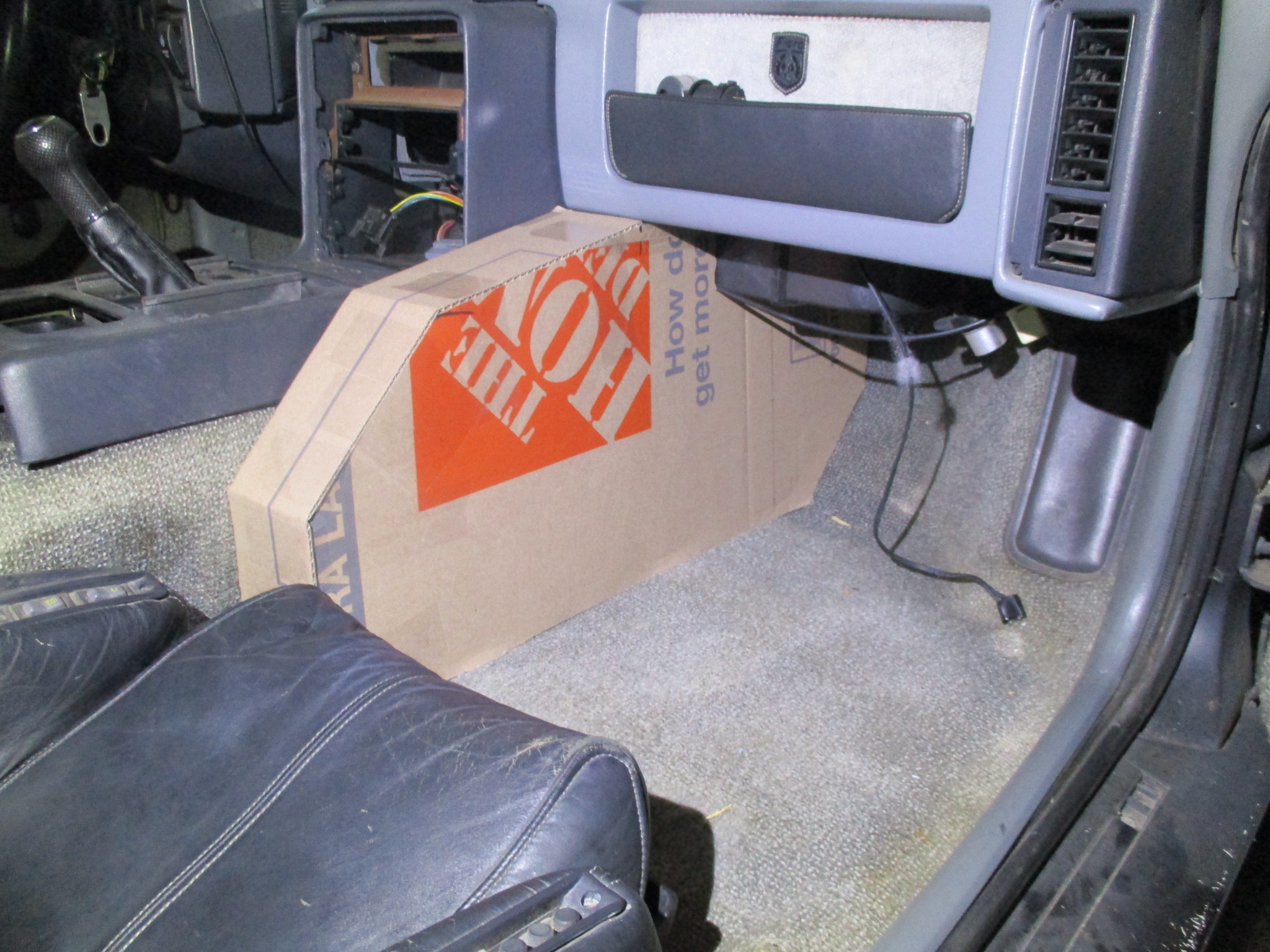
However, while I was messing with that box, I thought of another option... The passenger foot well has been done before, but this is a little different take on it. Basically the box hugs the side of the center console and extends from the face of the seat to the foot well at the very front. With it being 4" deep at the seat end, it ends up being about 5" deep in the foot well as the center console frame is tapered. This style box would allow me to run a ported 10" sub down in the foot well and under the dash with a port facing up right next to the HVAC control panel.
If I wanted the sub closer to the seat, then a 12" one will easily fit diameter wise, but the mounting depth would start to become a limiting factor.
Then it came to the subwoofer... the under dash box that Alex4mula made would allow an 8" sub. I made a mock up from card board (1 single piece, lots of cuts, bend slices and tape). I took out the stock sub housing with the modified tang bang and started to test fit. I still need to remove a couple of brackets to get it fully into place.
I made a mock-up like that a few years ago. It can be MUCH better by relocating the convenience center and blue dingy thingy--or rather the blue dingy thingy socket if you've properly removed the blue dingy thingy--somewhere else, allowing the box to occupy that volume in a more compact box shape. That results in better volume for an 8" sub.
If you gotta have a 10 or 12, your options in a Fiero are limited.
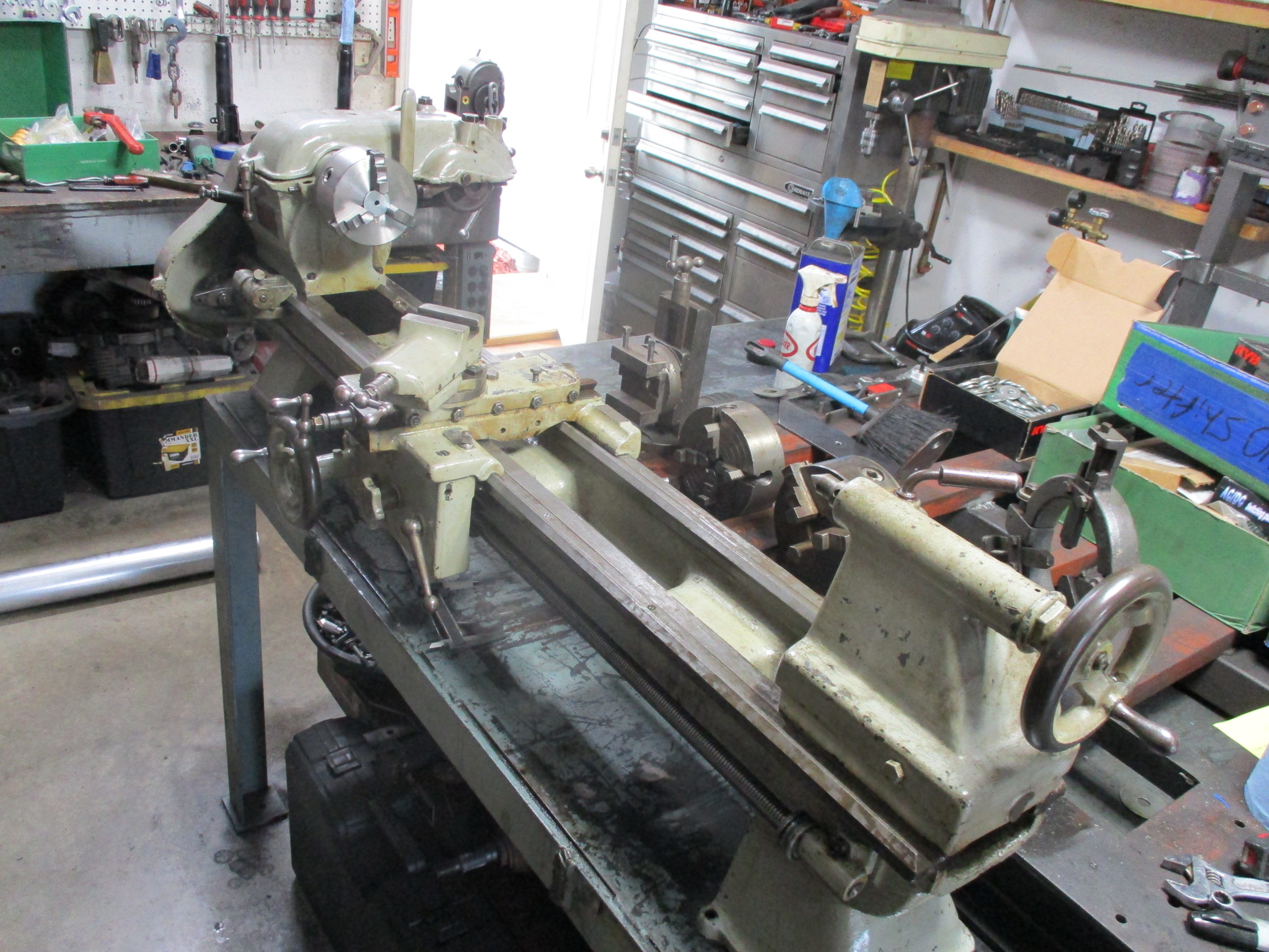
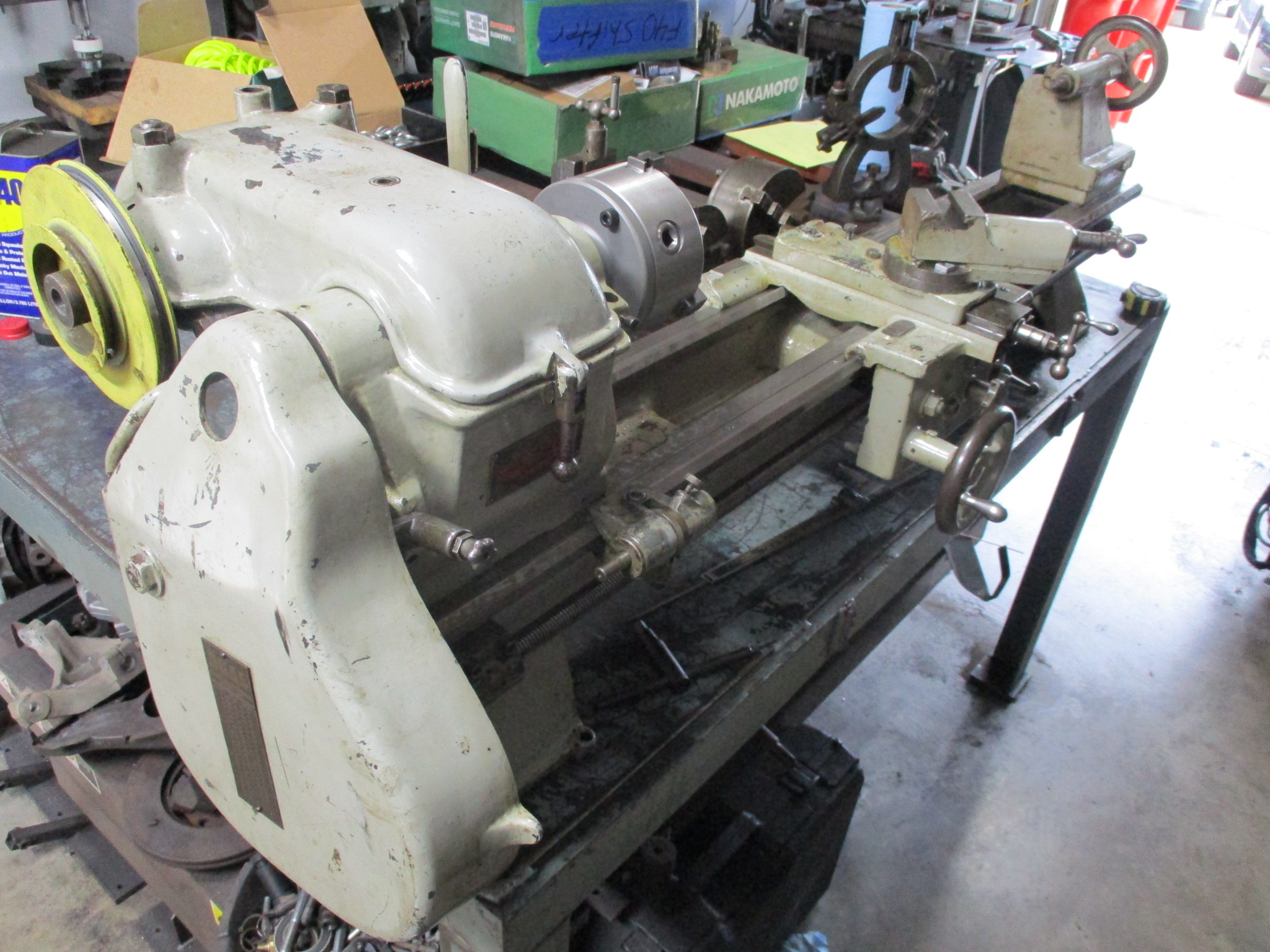
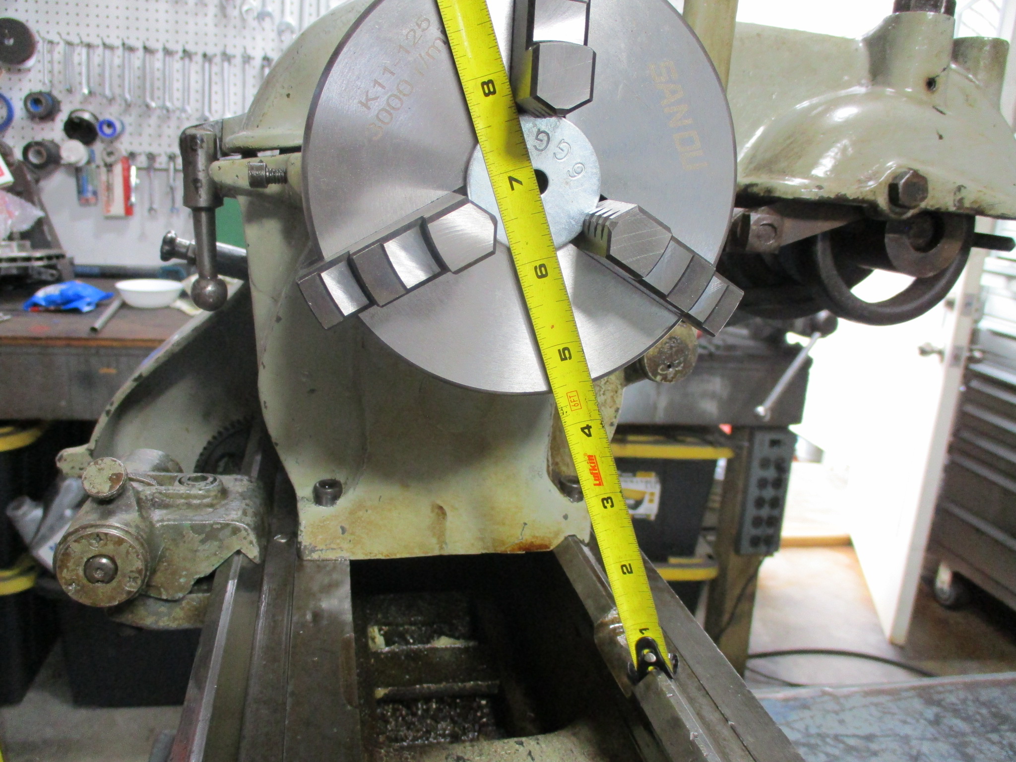
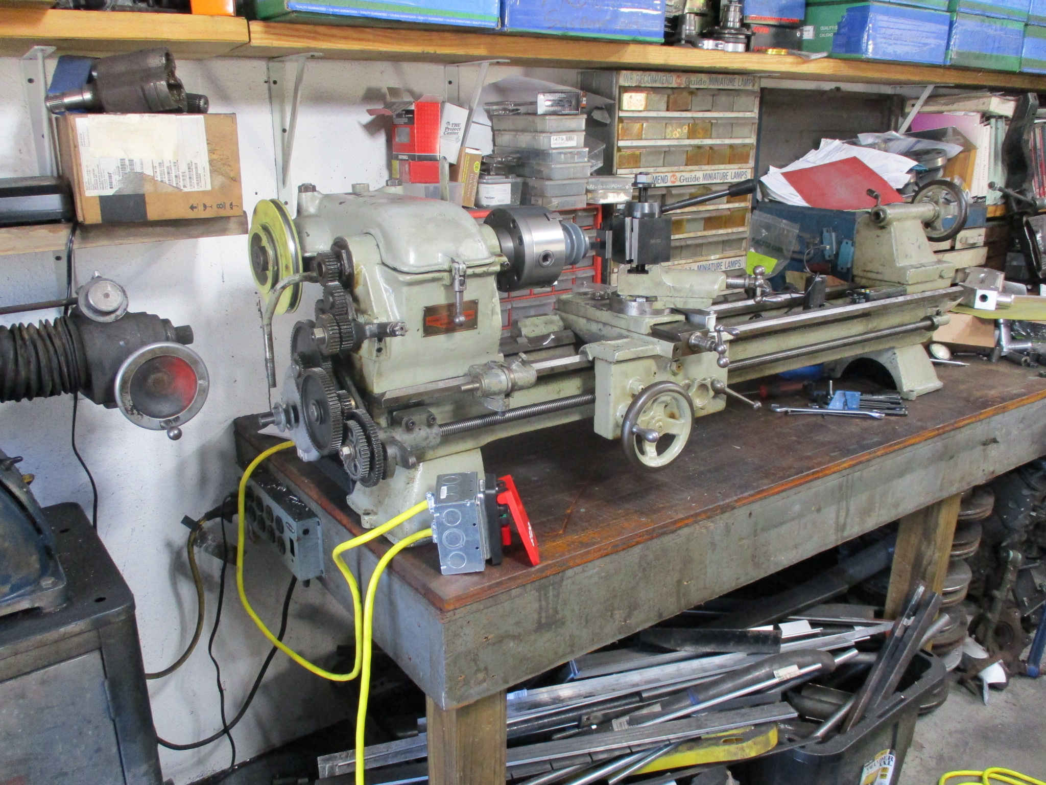
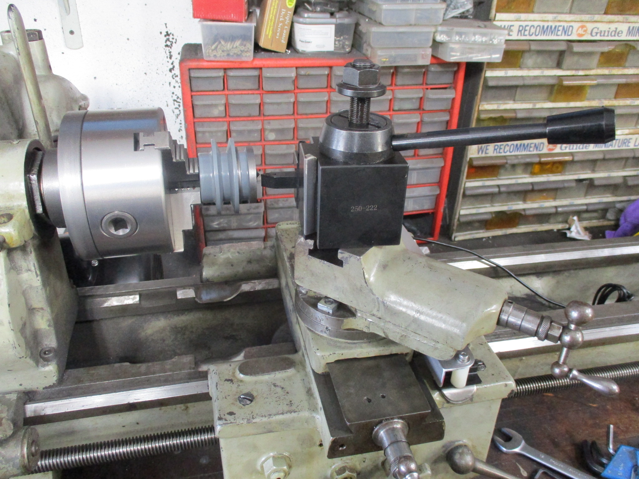
This past week a 12" Clausing 100 lathe popped up on Craigslist about 2 hours away. For some reason this 12" lathe is about 12 5/8" to the ways and a portion of the ways right by the chuck was modified to 13.5" (6.75" to the center). Since I was looking for one that would swing a thin 13 5/8 to 13 3/4 disk, I picked this lathe up and plan to use it to replace the 9" Southbend lathe and the Aamco 3000 brake lathe (working on freeing up space for the new CNC mill to arrive in Dec). I have already ordered the DROs for it and will pick up a new 120V 1ph motor for it (came with a 3000+ RPM 120v motor.
Picked up new 1750 RPM 120V motor Ordered dual pulley for motor (2" and 2 1/2") - this will give me 300, 500, 627, 833, 1045, 1741 rpm options Wired up motor to on/off switch Created captive nuts for the motor mount stands Mounted motor on mount stands and clamped them to the table Clamped the lathe to the table Test ran lathe Installed new chuck backing plate Trued up backing plate Installed chuck and verified trueness Installed cross side DRO (fabricated 2 brackets, drill/tap several holes) Modified the bed of the lathe in non-critical areas to fit a RWD LS flywheel
I still need to fab up everything for the main DRO and some chip guards for the DRO rails, then it will be time to start cleaning up the 9" one so it can find a new home.
After doing some tests with the Clausing, it was time to clean up the 9" Southbend and find a new owner. Here it is all cleaned up. I listed it pretty much as you see it here with everything shown.
I must have asked to little for it, had full asking price in cash in my hand in under 24 hours... It went to a good home.
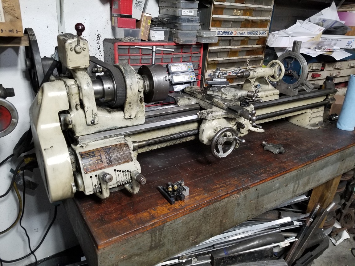
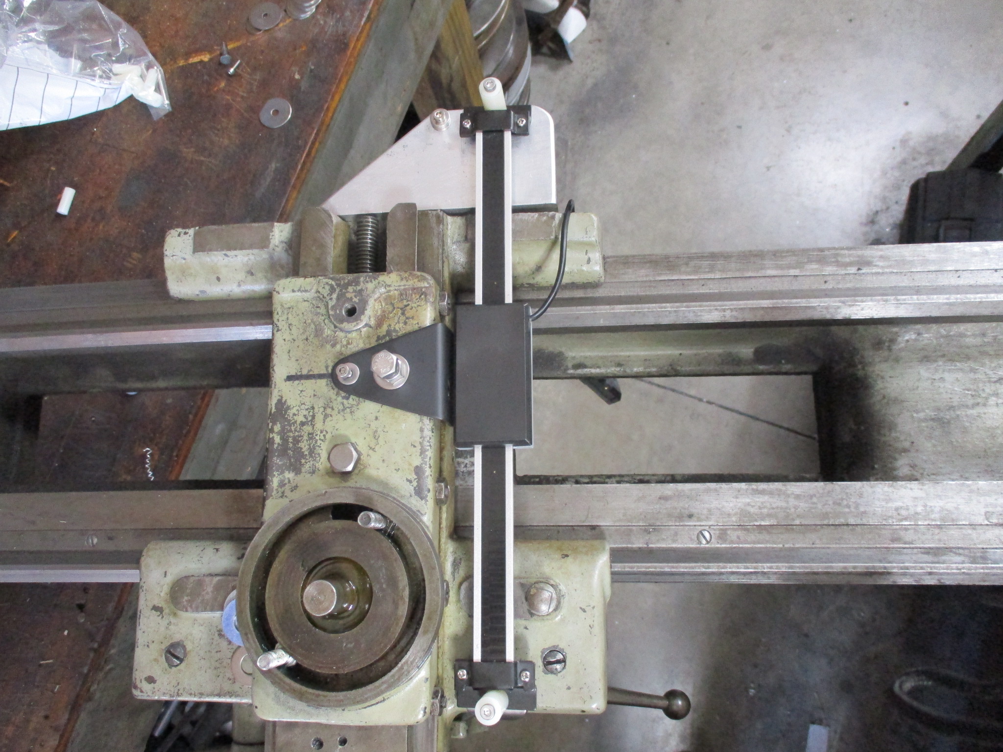
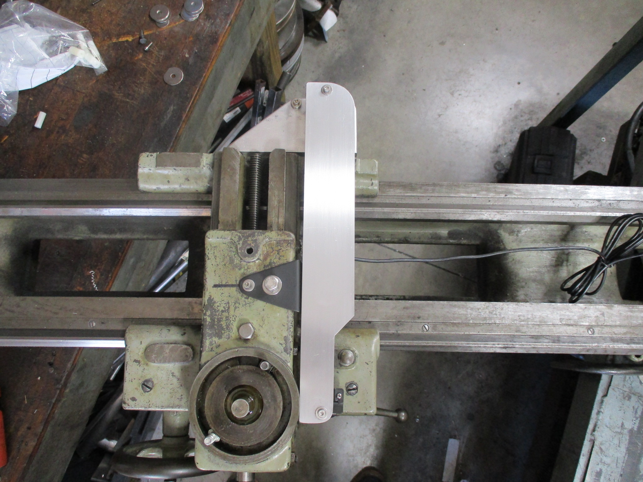
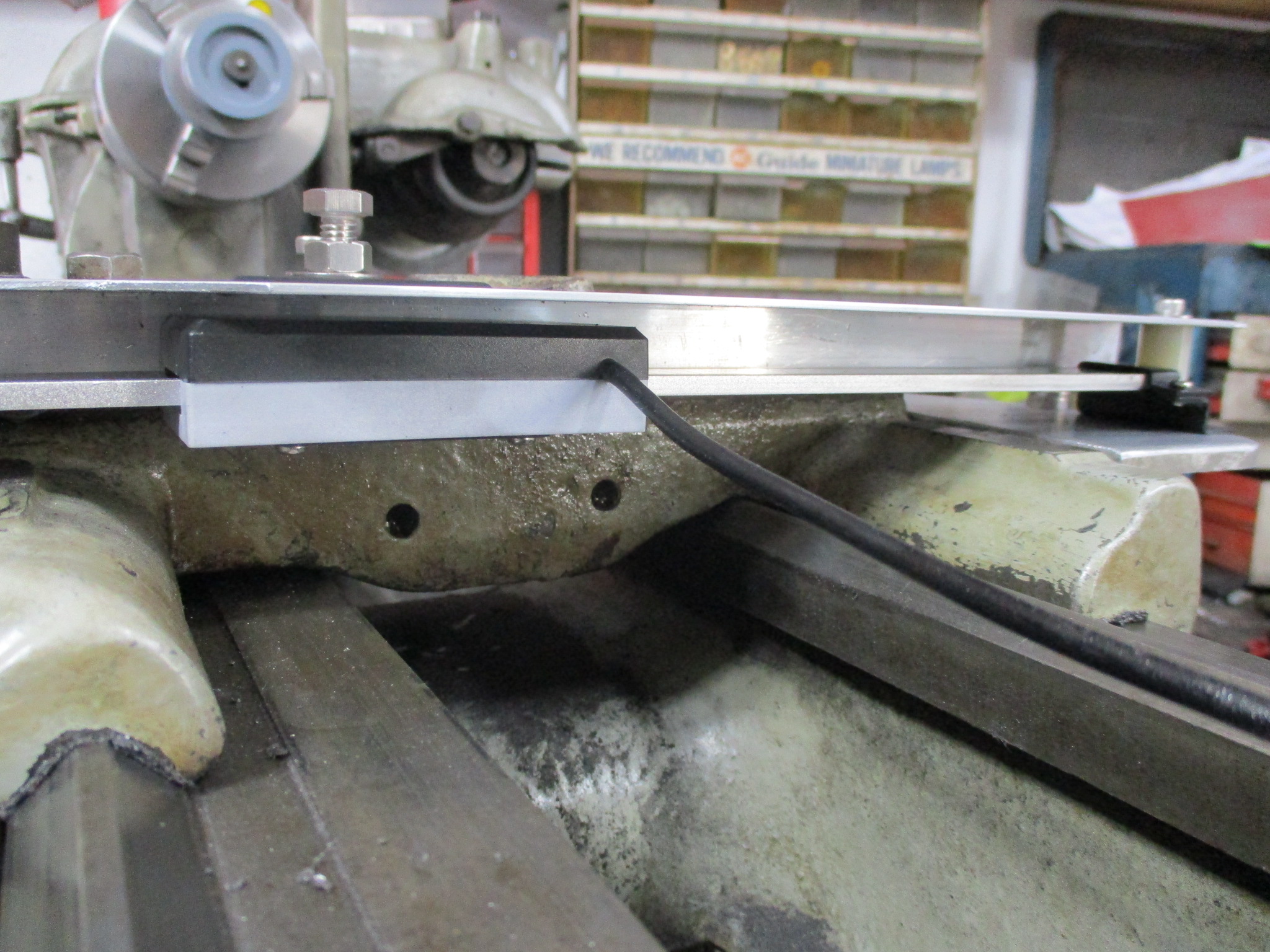
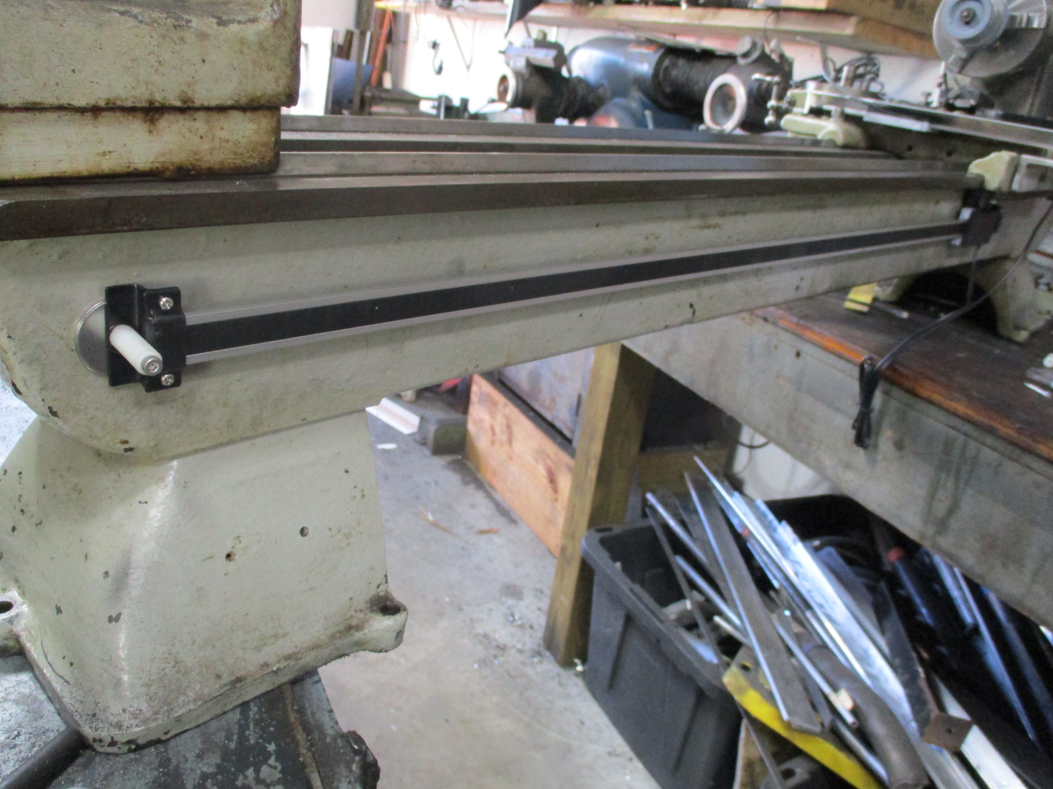
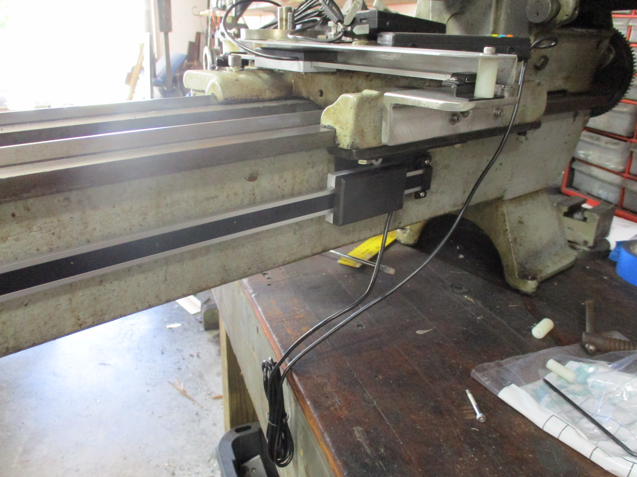
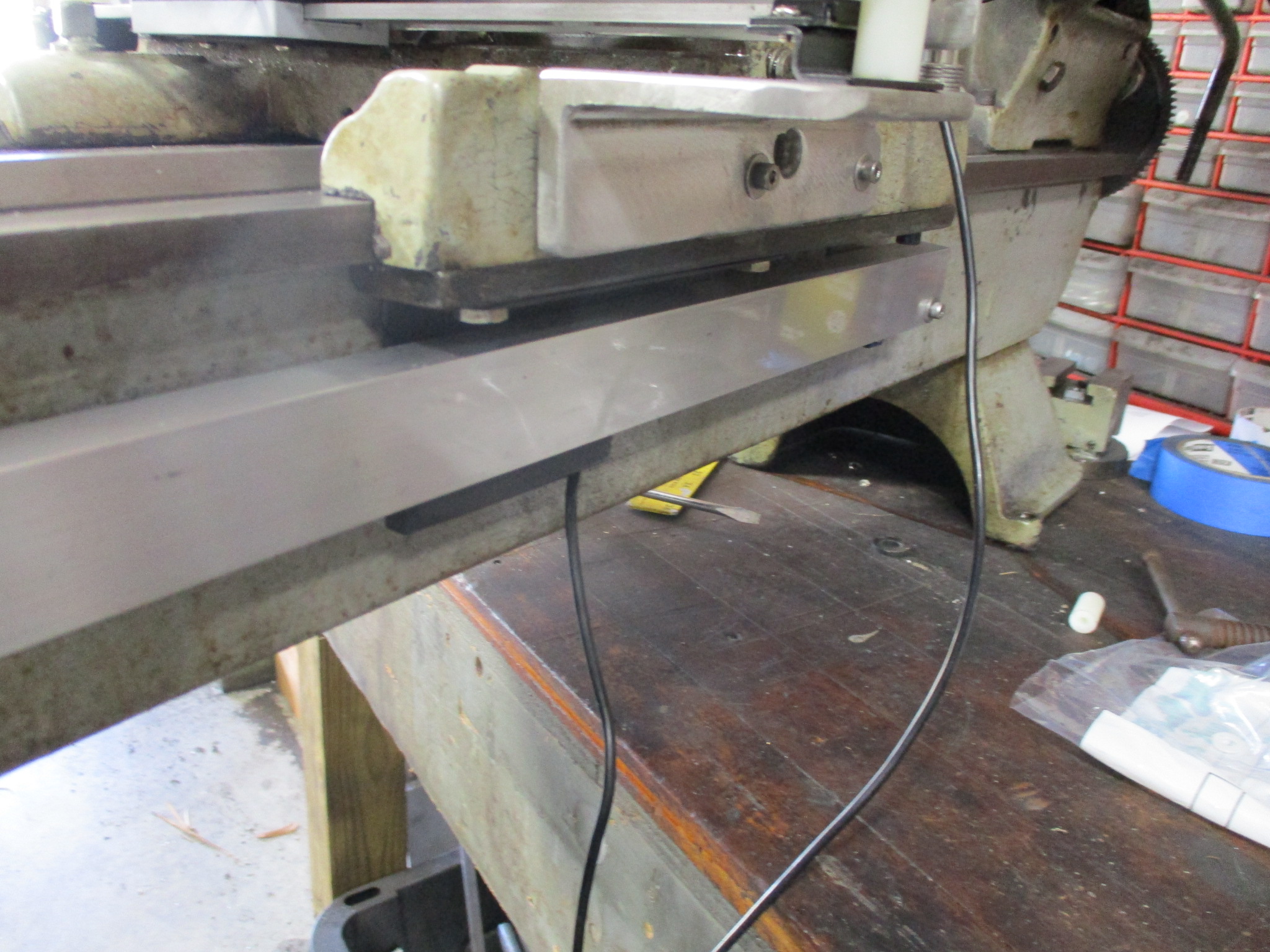
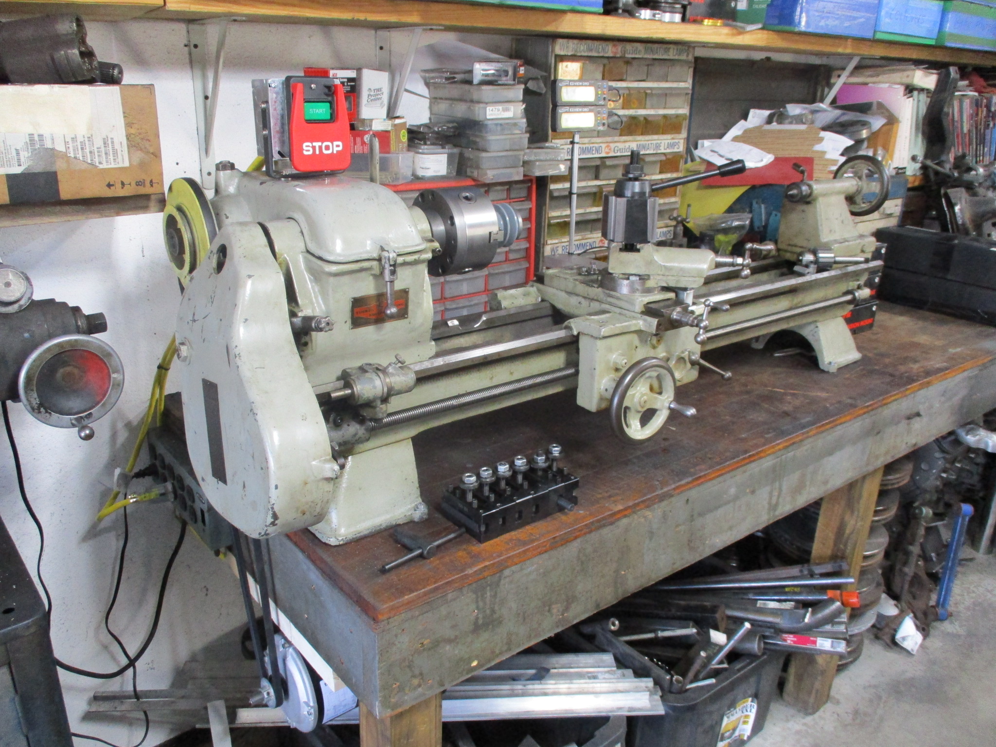
This weekend I finished up most of the DRO install on the Clausing. Similar install as I did on the Southbend, but took the extra step to add some chip shields for them. I found it easier to access both sides of the lathe with is spanning the walk way between the bench and the metal table.
After the DROs were mounted, The lathe was moved over to the work bench that would be its final home. I am still working through the final placement of the lathe as I would like to install a tool box for all the tooling against the wall and relocate the two sets of bins. The motor will be mounted under the bench (just shown on top so I could check belt alignment as well as where the mount holes would be), so I need to add some wood supports on the bottom side. I also need to find a spot to mount the DRO readouts as well as the start/stop button.
The new tool post and holder also arrived. A little larger than I needed, but all steel and will be very sturdy. You can also see I am in the middle of modifying a dual 2.6" pulley to a dual 2.6" and 2.0" pulley.
If everything goes to plan, I should be all done with the lathe replacement by the end of next weekend...
The lathe replacement project is pretty much done at this point.
Finished the motor mount frame under the table. Verified and purchased proper length of belt. Determined location of start/stop and fabricated a bracket to hold the box. Made tube/threaded rod to hold the DRO displays. Bolted the lathe to the table. Setup all my cutters in the new holders and set the holders to the right height. The 26x18 aluminum cookie sheets for chip trays came with lots of perforated holes, so I sent them back and order a new set.
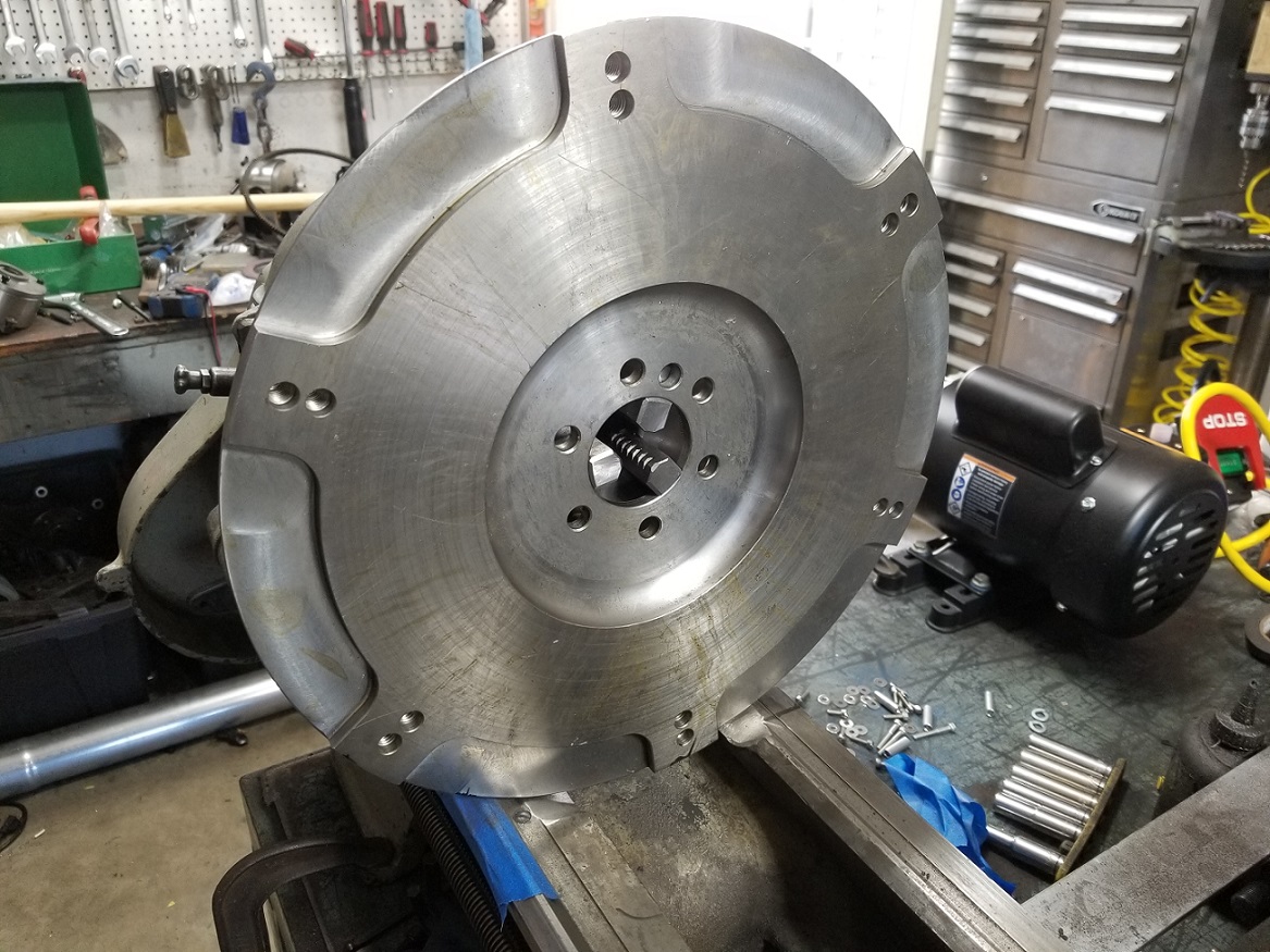
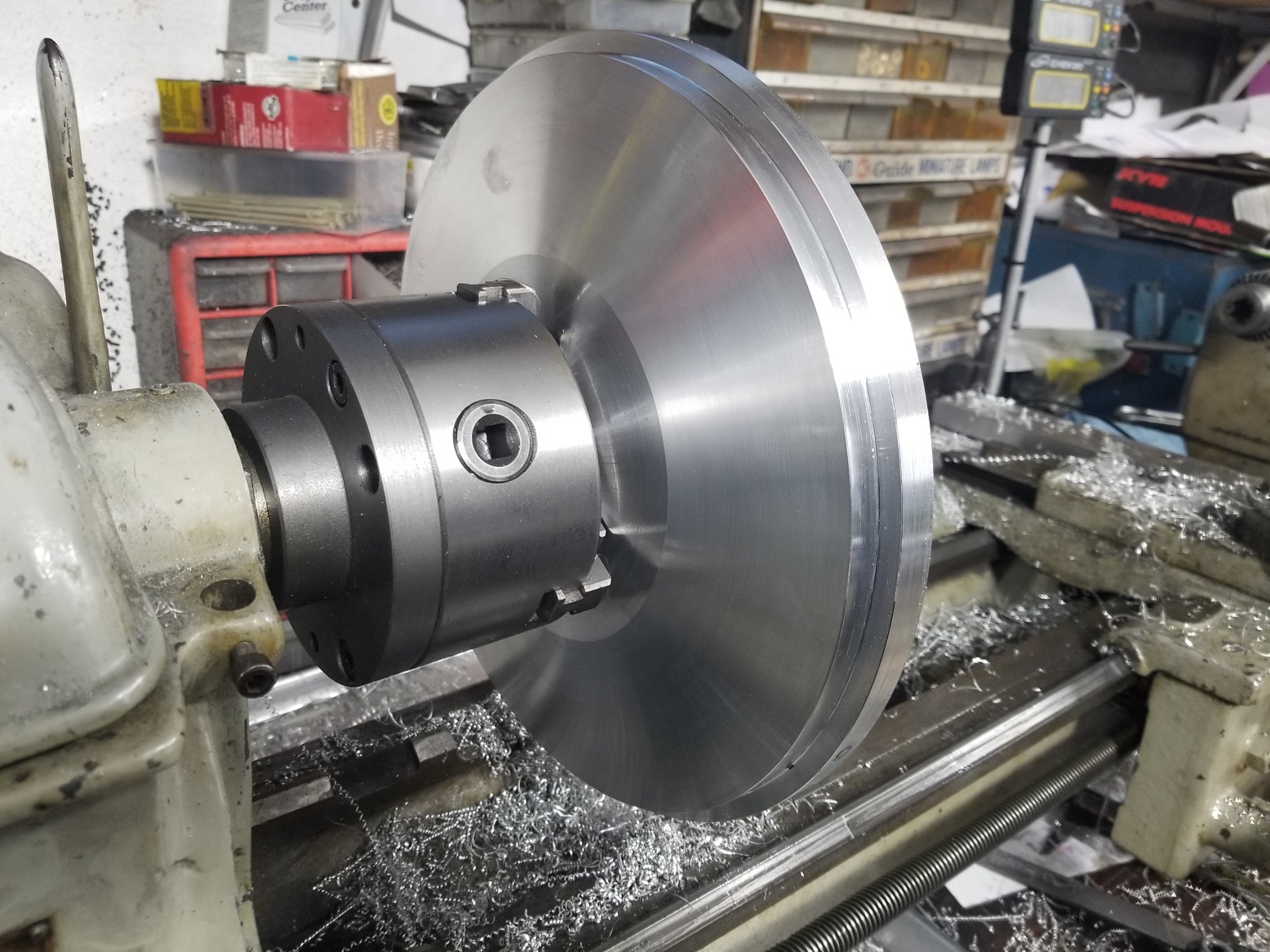
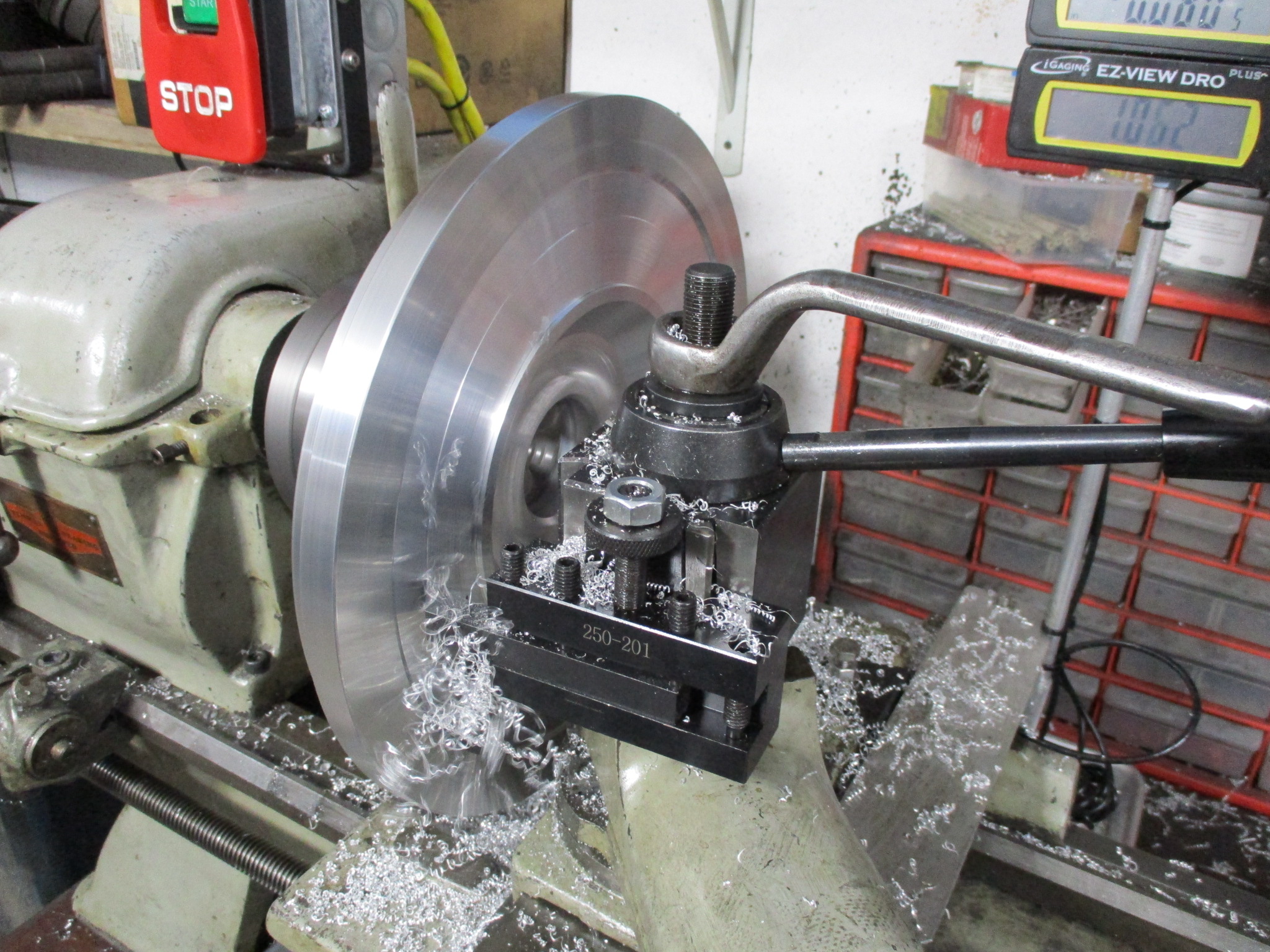
The 12" lathe has been busy - and this was a primary reason for upsizing...
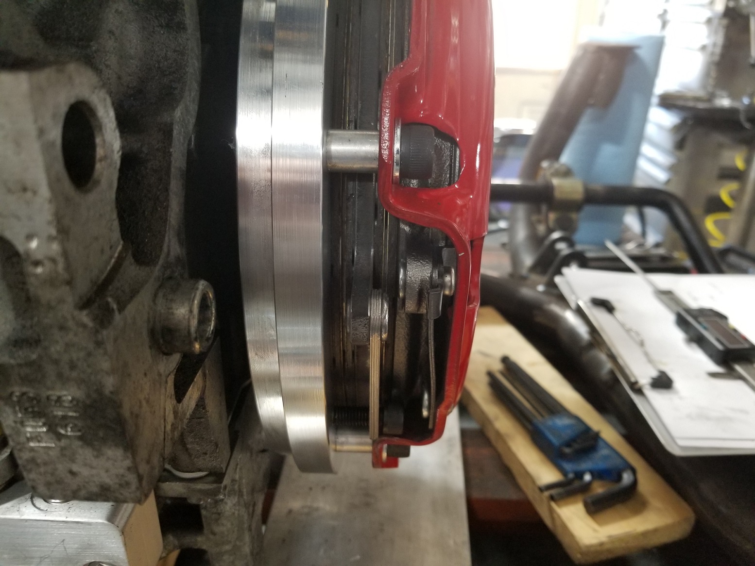
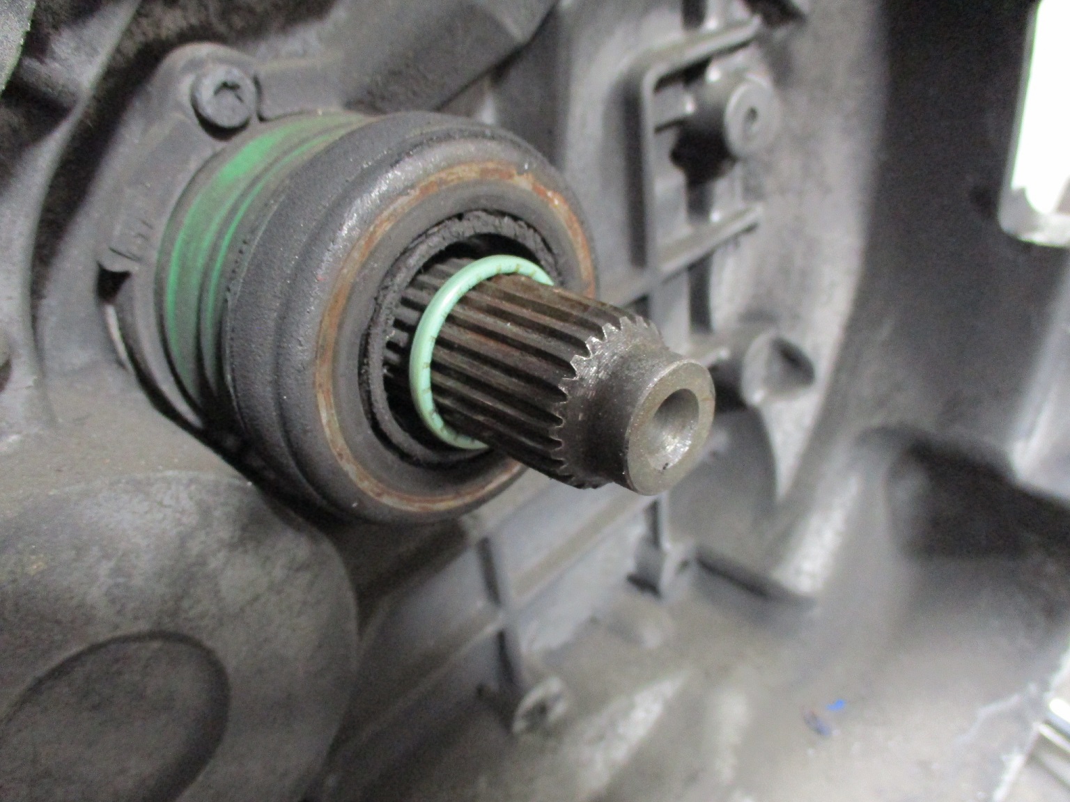
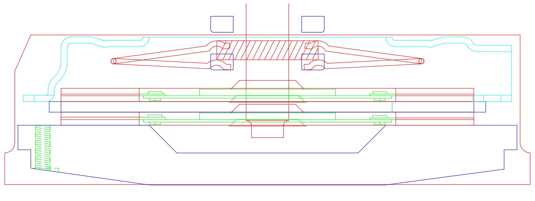
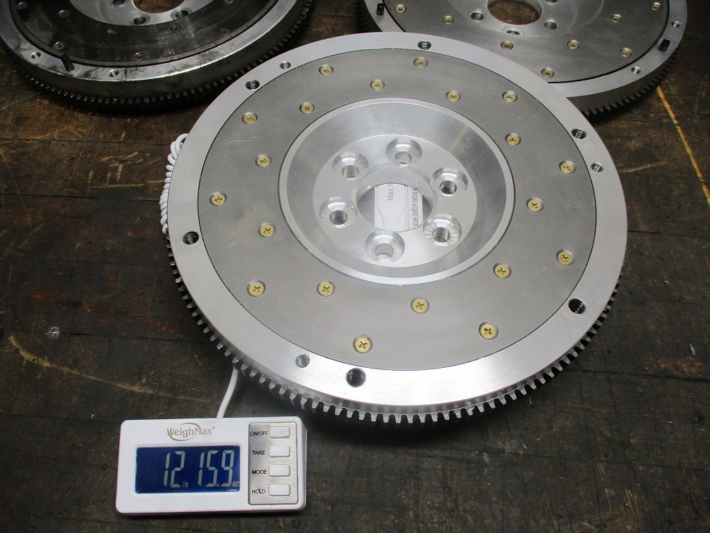
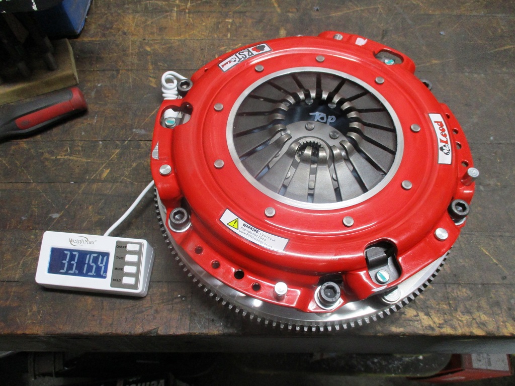
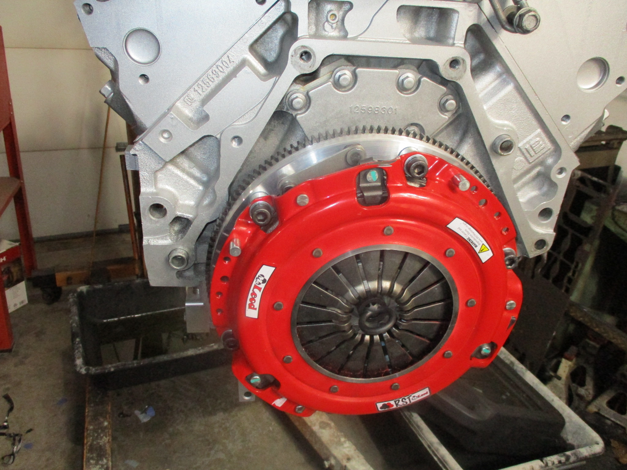
New custom flywheel for dual disc clutch. It is a super tight fit, but with a couple of minor modifications to the pressure plate, I was able to get full spline engagement on both discs as well as adequate finger clearance for wear. This clutch uses organic clutch material like OEM for good drivability and is rated for 800 hp, which should hold the 550+ rwhp I plan to throw at it.
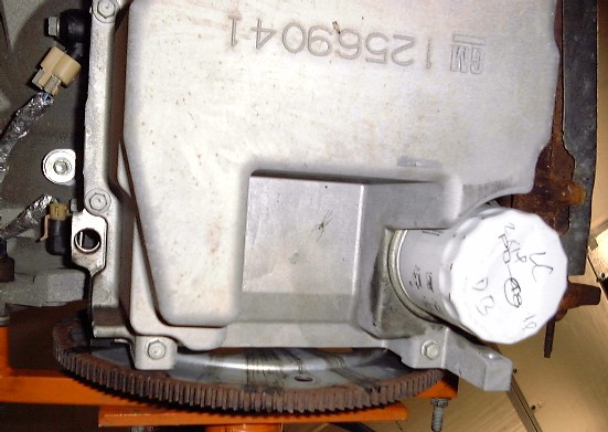
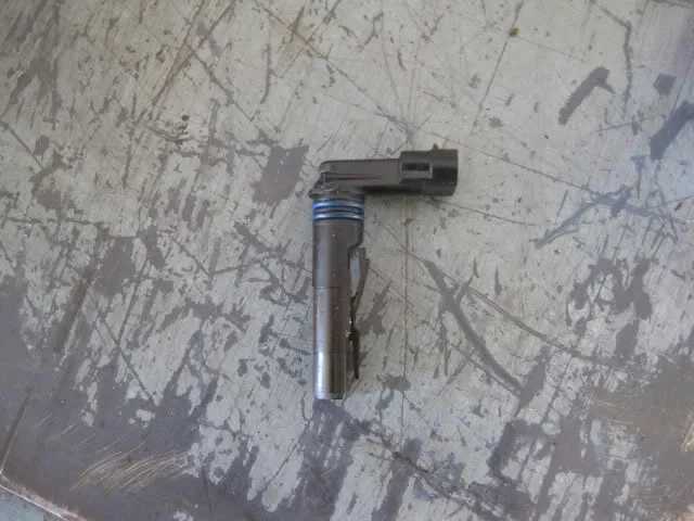
Wow. Go away for 10 years and they change everything around on you! I'm WAYYY back near the start after taking almost 10 yrs off my build due to life and work and other issues, but they're over now and I'm in shape to purse that - the 'straightforward' LS4/F40 swap. (No turbo - I need to get caught up on this, too!) Anyway, a basic question I hope nobody minds: I'm back nearly on page 1, adapting an LS2 intake over the DoD valley plate and (10 years, sigh) parts have somehow gone missing. I can't find THIS, and I can't come up with a name that Rockauto or Summit or anyone can source it by. Does anyone have a name/link etc for this please? It's 5 pin and I've tried all kinds of names. Any help appreciated!! And thanks to fieroguru, ongoing, for his impeccable documentation. Edit; not sure the image is showing. It's the pressure sensor that mounts under the TB end of the intake manifold. Guru did a fair bit of mods to get it to fit in that tight space.
[This message has been edited by 85-308 (edited 11-28-2022).]
That connector is part of the Valve Lifter Oil Manifold Assembly. I don't think gm sells it individually.
You only need it if you are planning to keep Displacement on demand. Lots of people delete displacement on demand and replace the valley cover with one from an LS2.
That connector is part of the Valve Lifter Oil Manifold Assembly. I don't think gm sells it individually. That explains much! Thanks.
You only need it if you are planning to keep Displacement on demand. Lots of people delete displacement on demand and replace the valley cover with one from an LS2.
Exactly what I am doing. Again, thanks for the prompt reply. Saved me hours (this AM) trying to figure out what it was/did/is named. Much appreciated! GP
PS: I'll be ordering a few more things as soon as I get a complete order together for you. The passage of time has made a few of the things I got 'lose' parts... sigh.
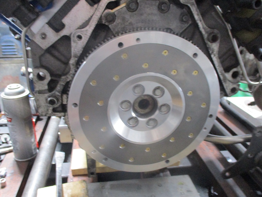
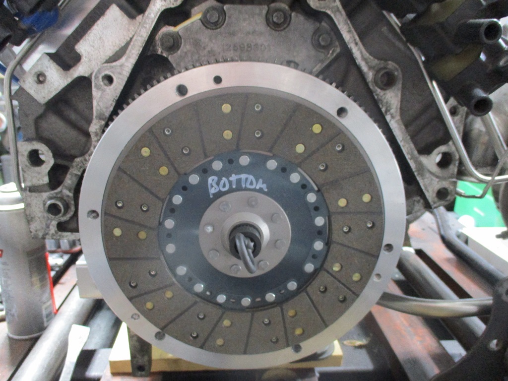
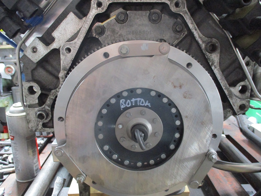
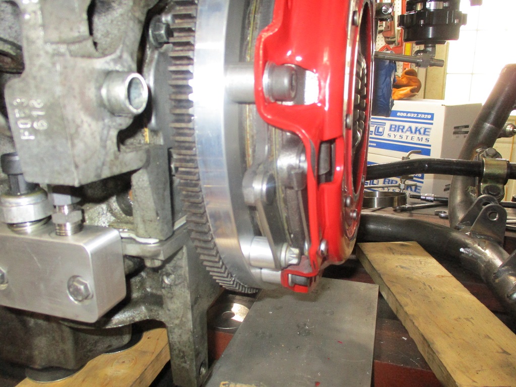
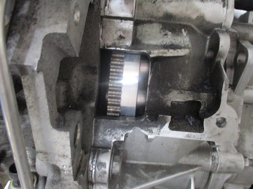
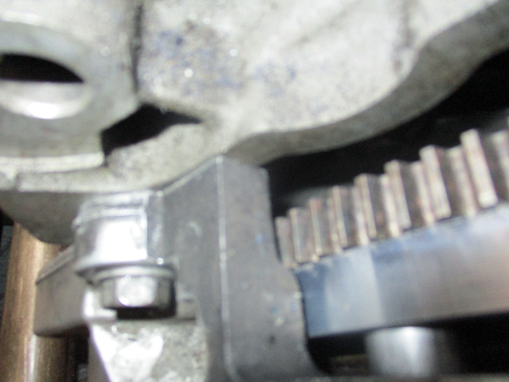
Sequence of installation Flywheel: Bottom Disc: Floater Plate: For some reason I missed taking a picture of the top disk.
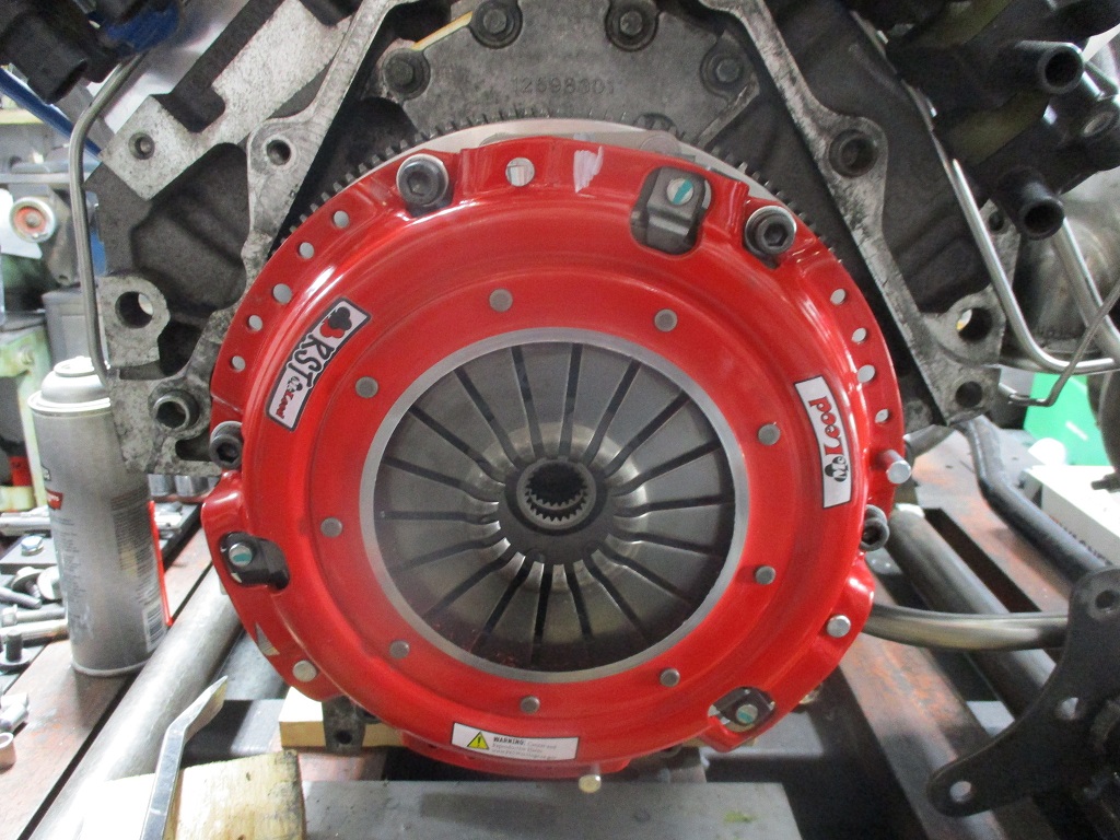
Pressure plate: Transmission installed:
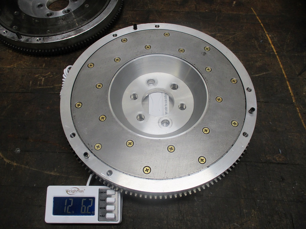
With my quest for weight offsetting for the turbo bits, the twin disc clutch is definitely heavier than my last setup. However, like the turbo, the additional weigh is needed to hold up to 800 hp while keeping the car daily driver friendly, but the additional weight was still kept to a minimum.
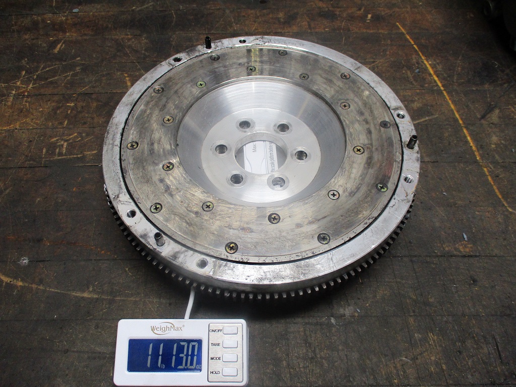
For comparison, a stock 2.8 fiero setup is about 15 lbs for the flywheel and 15.6 lbs for the clutch/pressure plate = 30.65 lbs. LS4/F40 Spec Stage 4+ combo is 11.2 lbs for the flywheel and 28 lbs total after 55K miles of use. Stock 2000 LS1 is 24 lbs for the flywheel and 32 lbs for the clutch/pressure plate = 56 lbs and this weight is spread over a 2" larger diameter. LS4/F40 flywheel/twin disc clutch combo is 13 lbs for the flywheel, and 21 lbs for the clutch discs, floater plate, pressure plate and all bolts. = 34 lbs So the setup will be about 3.5 lbs heavier than stock Fiero and 22 lbs lighter than a stock LS1 clutch setup.
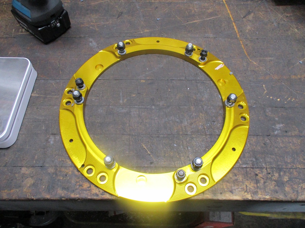
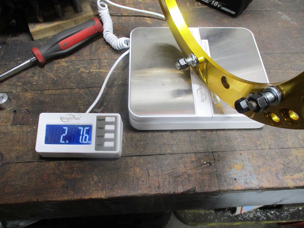
The clutch did come with this plate so that it could reuse the stock flywheel/pressure plate bolt patterns... I tossed it as it wasn't needed. This saved 2.5 lbs off the clutch kit as delivered.
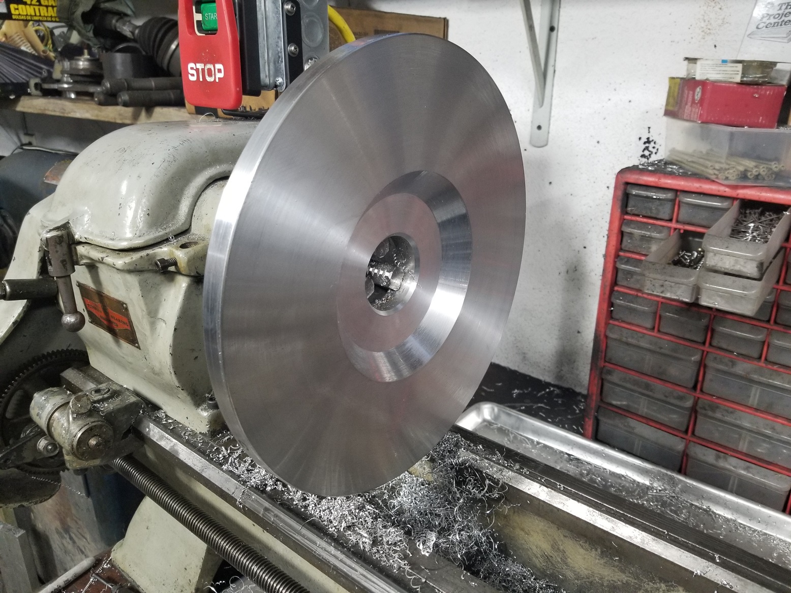
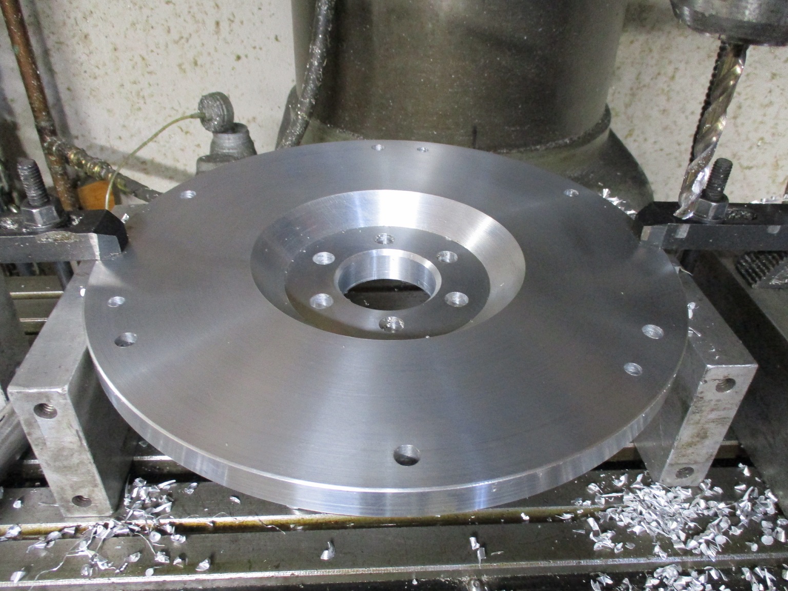
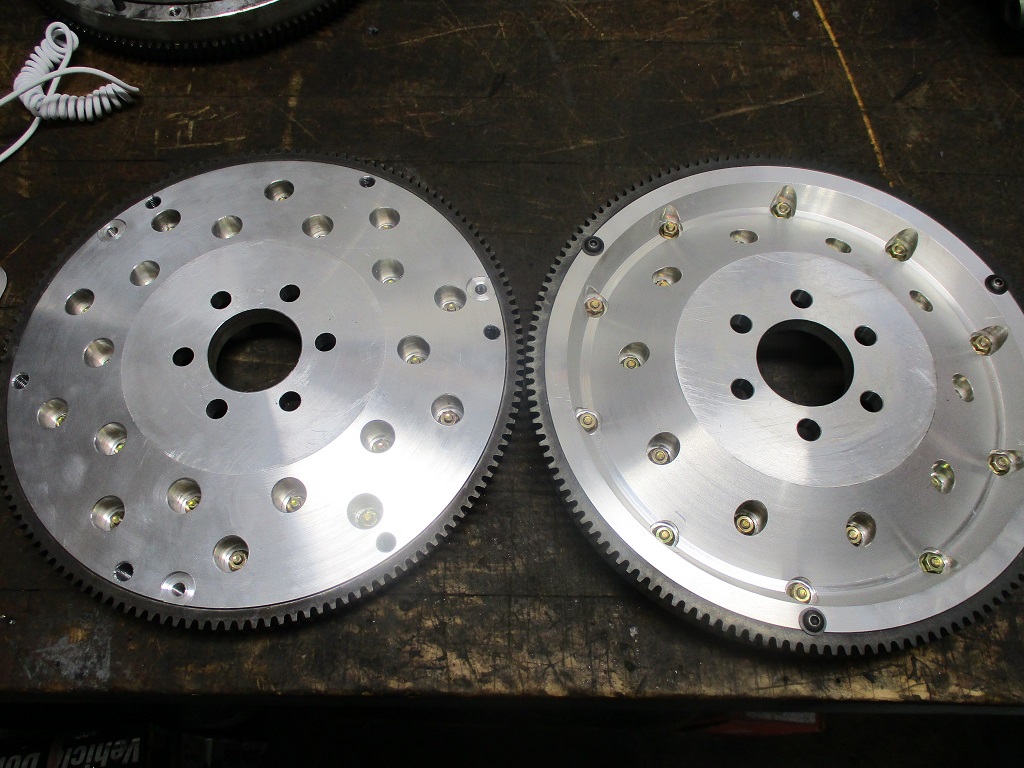
Here is a history of my LS4 flywheels: Original prototype (after 55k miles) - fabricated with manual lathe and mill:
CNC version of original from small batch run:
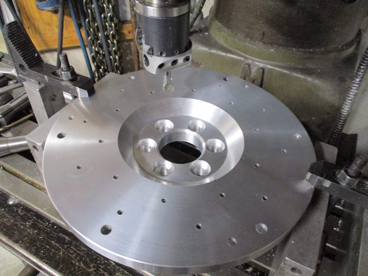
Protype of the twin disc version - fabricated with manual lathe and mill:
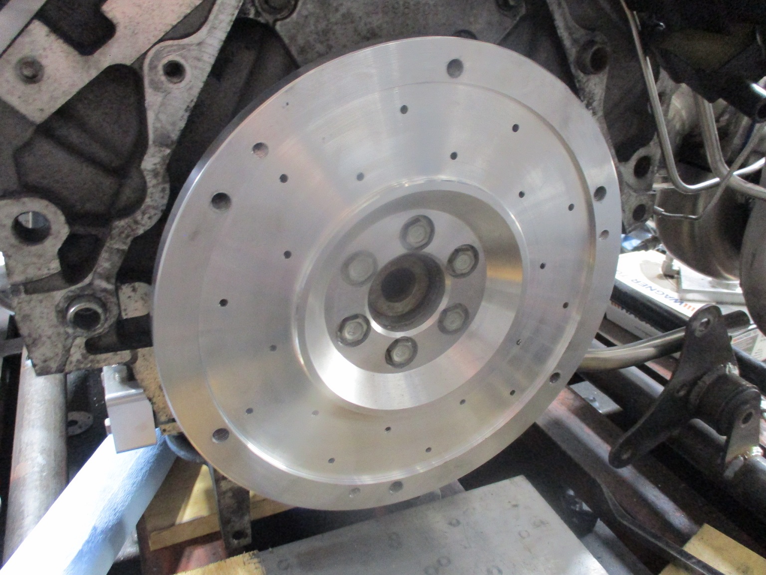
The twin disc version is heavier as there is minimal material taken off the backside:
Now it is pretty much time to start cleaning things, sand blasting them and starting to make then look pretty.
[This message has been edited by fieroguru (edited 12-18-2022).]
I'm guessing because of how particular dimensions are between engine/trans combos, this isn't something that would make it to your products page, except for LS4/F40 folks?
I'm guessing because of how particular dimensions are between engine/trans combos, this isn't something that would make it to your products page, except for LS4/F40 folks?
Vince, right now, my primary focus with this flywheel/clutch setup is getting something that will work (streetable and hold) in my car so I can get it back on the road in 2023. Finding a viable manufacturing plan for it is a rabbit hole I am not going down anytime soon. It will likely require a different pressure plate, which likely will require a flywheel redesign.
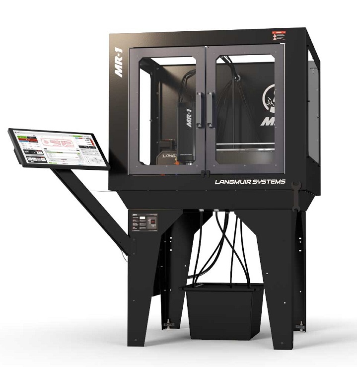
I was notified my mill is about 2 weeks from shipment and made the final payment. Started reading through the assembly instructions... going to take quite a bit of work.
out of curiosity, why didn't you get a CNC conversion for your existing mill?
------------------ "I am not what you so glibly call to be a civilized man. I have broken with society for reasons which I alone am able to appreciate. I am therefore not subject to it's stupid laws, and I ask you to never allude to them in my presence again."
I invited Lou Dias to trash me in my own thread, he refused. sorry. if he trashes your thread going after me. I tried.
Rebuilding and retrofitting my manual mill to CNC would have been too much of a project and the enclosure for flood coolant would have been very, very large. It basically came down to me wanting a newer more compact CNC unit.
That CNC looks sweet, is it able to recycle the coolant? Do you have to clean the chips out manually? I miss the days of being able to use the HAAS CNC mills at WPI.
That CNC looks sweet, is it able to recycle the coolant? Do you have to clean the chips out manually? I miss the days of being able to use the HAAS CNC mills at WPI.
Yes, there are drains in all 4 corners to drain the coolant back to the sump so it can be used again. Chip removal will be a manual process
Rebuilding and retrofitting my manual mill to CNC would have been too much of a project and the enclosure for flood coolant would have been very, very large. It basically came down to me wanting a newer more compact CNC unit.
I guess I was just thinking about the CNC Bridgeport style vertical mills I sometimes run at work, they don't have an enclosure. I can definitely understand wanting newer, better equipment, and wanting an enclosed unit, especially with minimal available space.
------------------ "I am not what you so glibly call to be a civilized man. I have broken with society for reasons which I alone am able to appreciate. I am therefore not subject to it's stupid laws, and I ask you to never allude to them in my presence again."
I invited Lou Dias to trash me in my own thread, he refused. sorry. if he trashes your thread going after me. I tried.
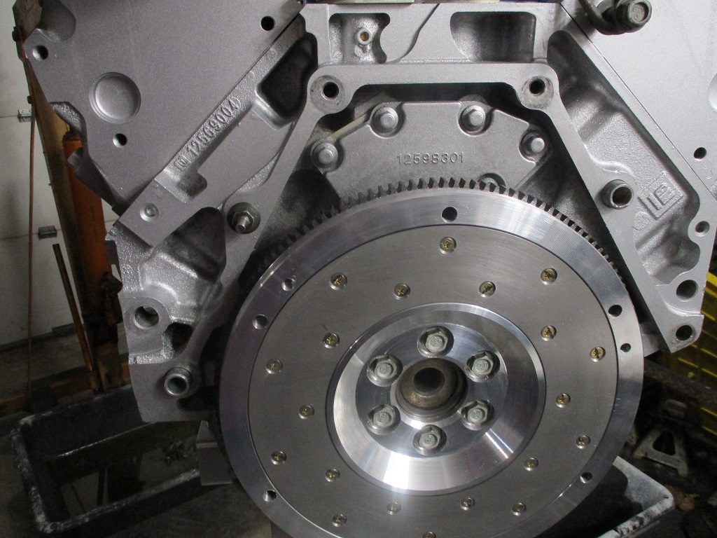
Spent the last few weeks cleaning and painting the engine and transmission, but it was time to get the engine/transmissions back together and back on the work table.
I installed the flywheel and clutch for the last time, applied Loctite and torqued all the bolts.
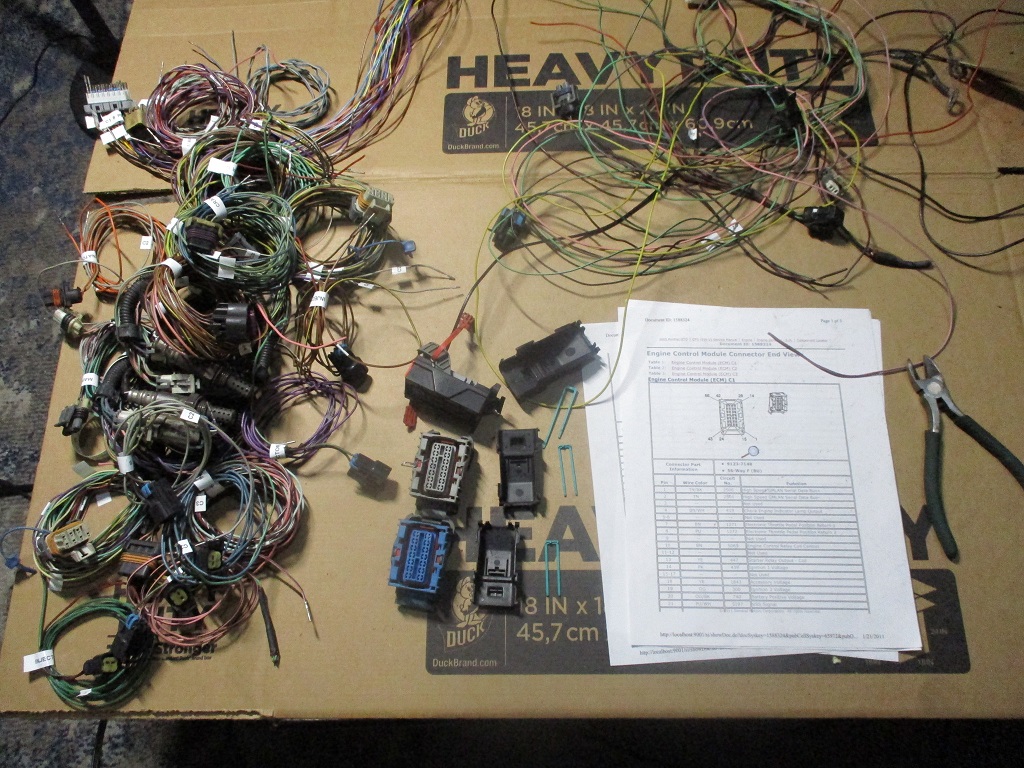
Also started the process of de-pinning the E40 ecm connectors (Sara is already asking how much longer this will be in the living room!)...
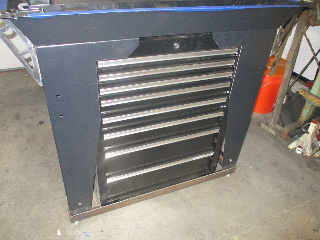
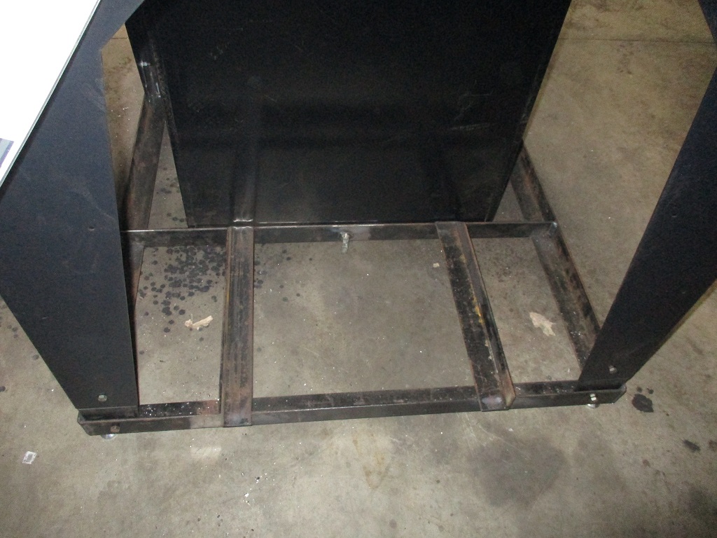
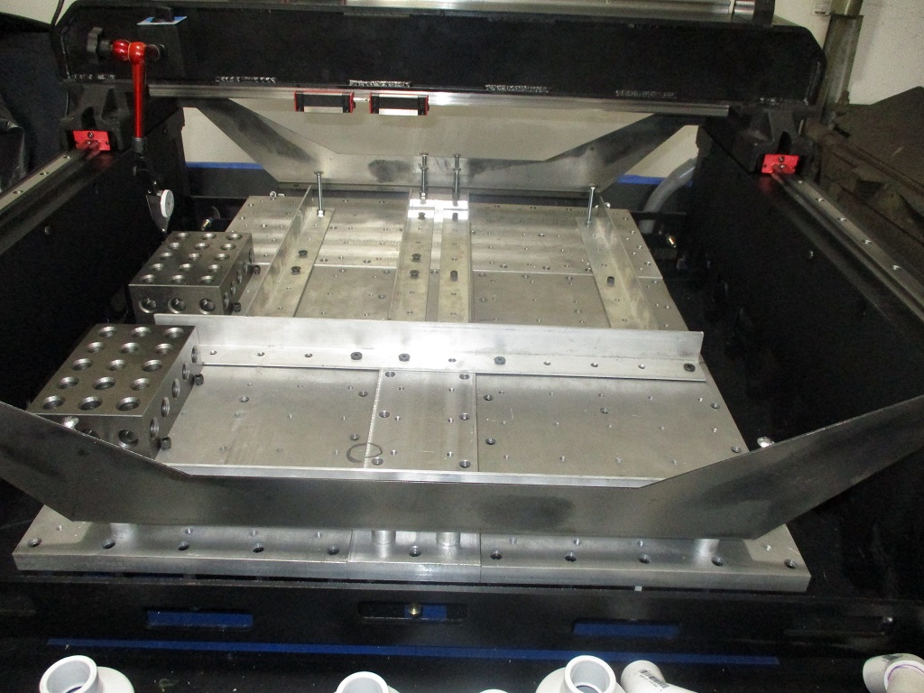
The MR1 mill arrives tomorrow, so assembling it (and modifying it) will be the major work for the next several weeks. I am going to enlarge the baseplate area (so there is room to add a 4th axis), raise & reinforce the X & Y rails up to 2" (so the vices and clamps don't use part of the milling window), extend the legs a few inches, incorporate a tool box to the bottom for all mill tooling and stuff, and some lifting points on the sides. It is going to be a fun project!
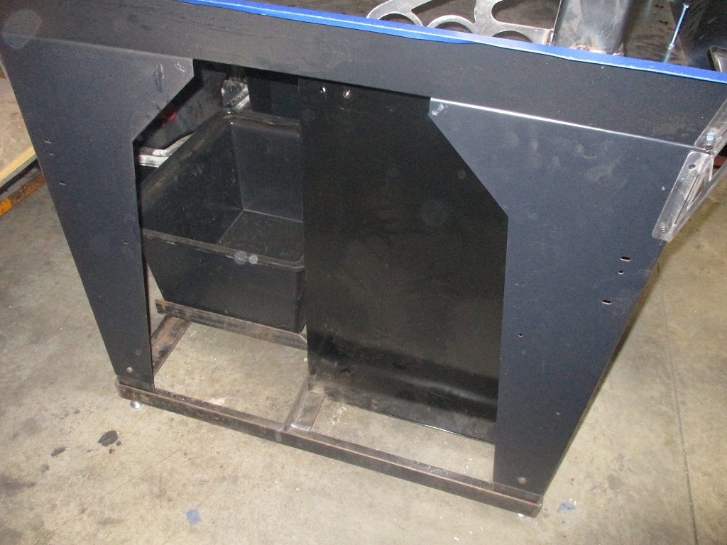
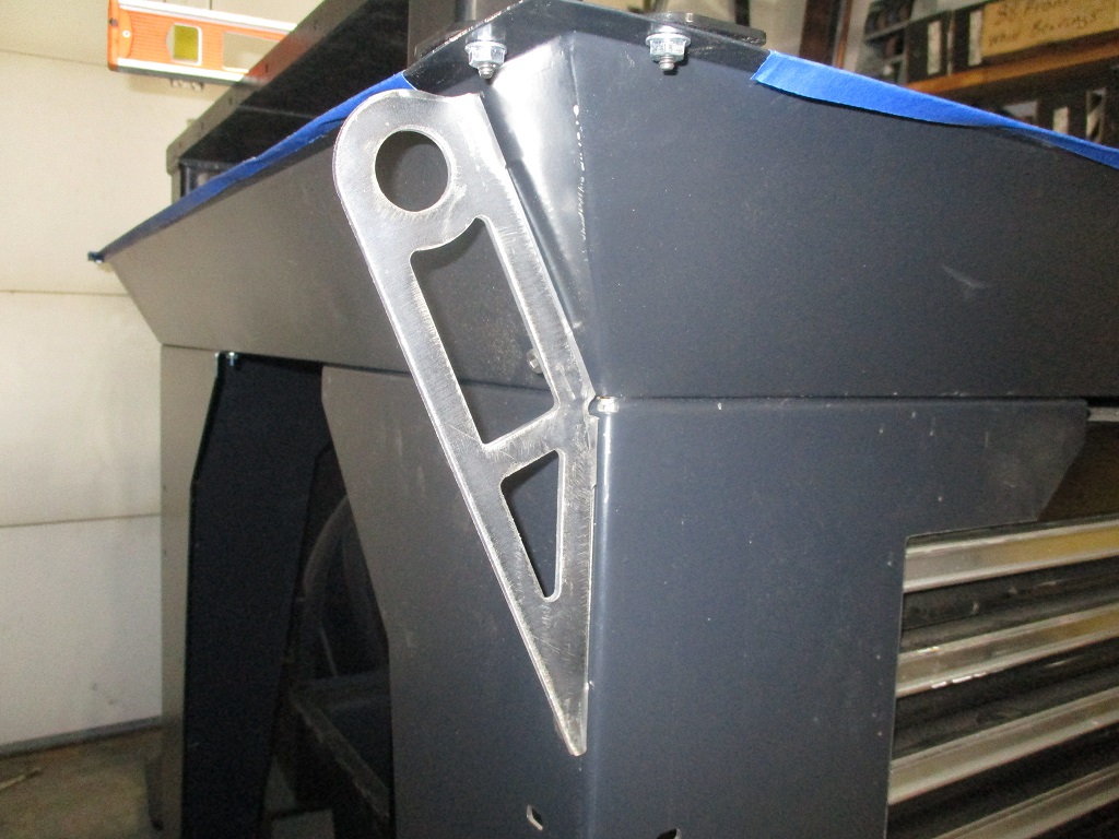
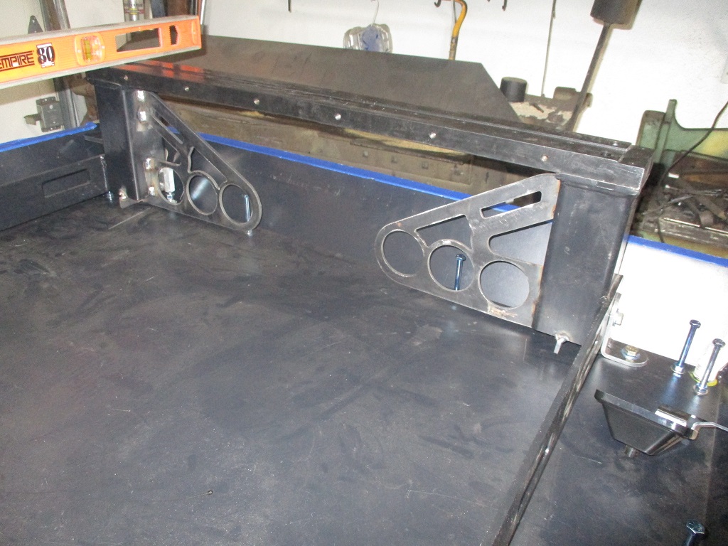
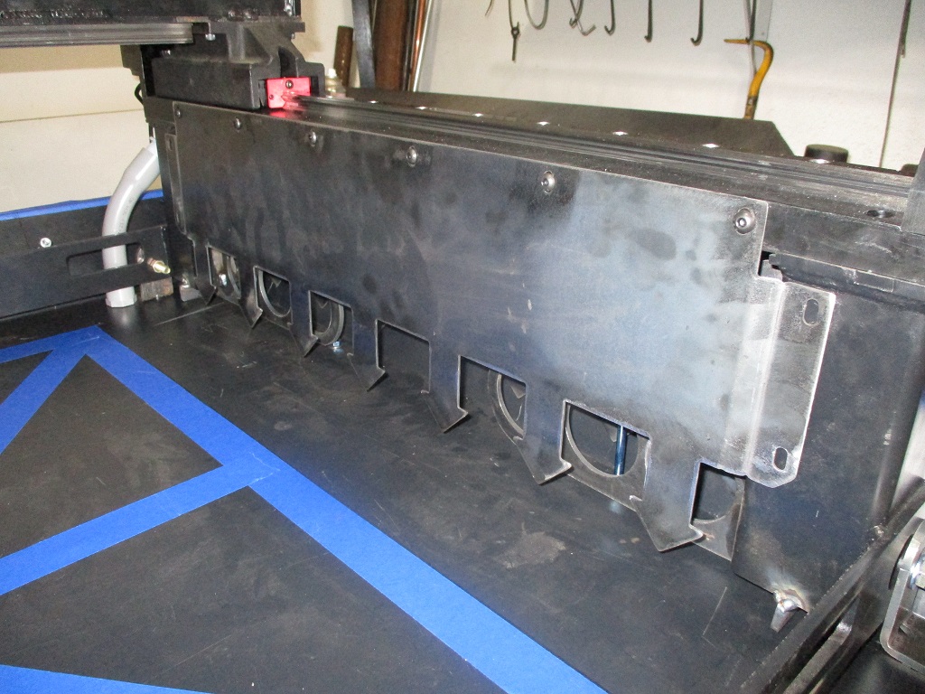
Added tool box Made brackets to extend legs Made 2x2x3/16 angle base for the legs, tool box and coolant flood tank Made lift brackets for the 4 corners Started raising the Y-rails - added jack bolts to level, brackets to hold the rails in place, and gussets to engage more of the concrete.
The y-rail side plates are now too short to seal at the bottom, so a new one was made that was 3/4" taller. It is also wider so the sides can be offset and bolt to the verticals of the Y rails. Bolting these side rails to the verticals is key to sealing the space under the y-rails as well as holding the verticals in position during the pour with the top of the Y-rails removed.
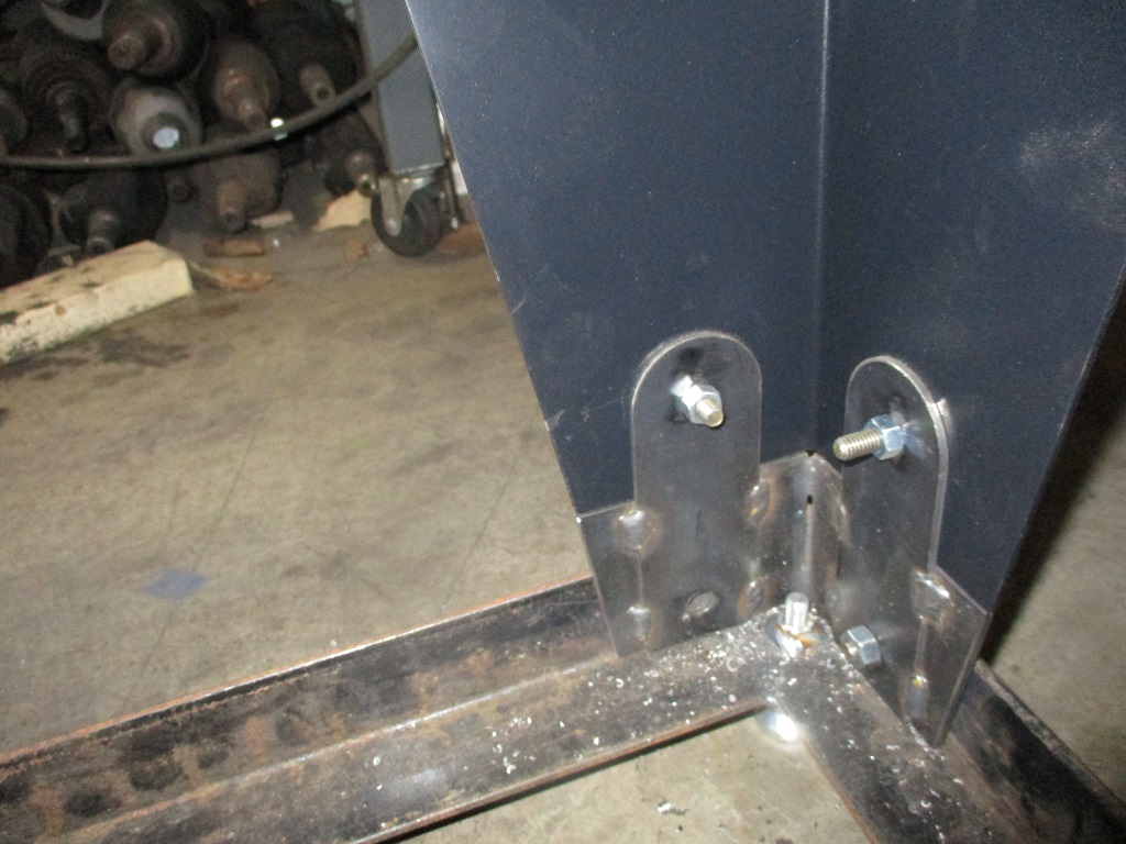
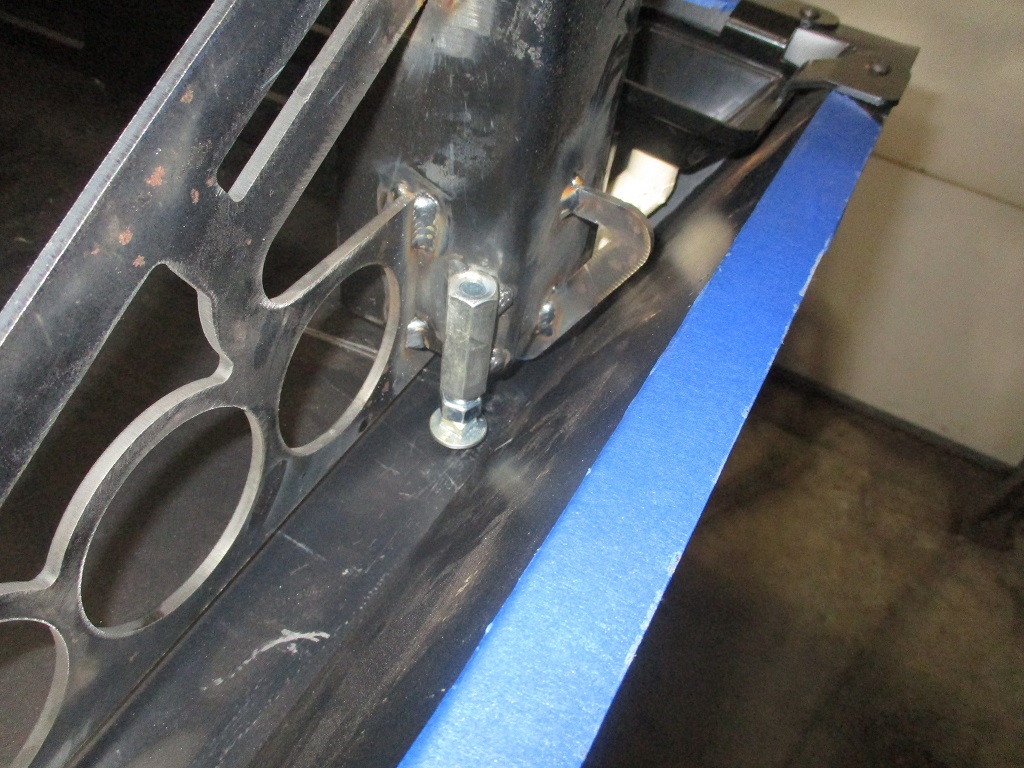
My machinist level came in so, I spent some time releveling the pan, then the Y-rails, and then added some brackets to hold the rails after I squared them up (picture of bracket a little later). I still need to double check co-planarity with the Langmuir tool, but suspect it will be close.
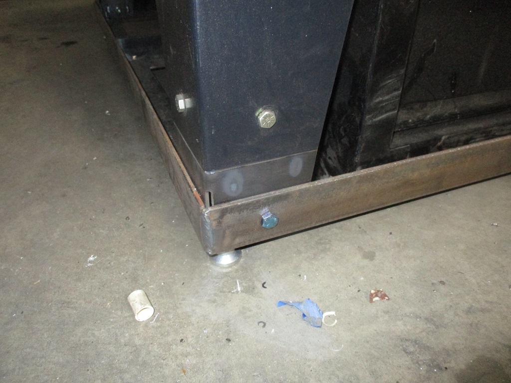
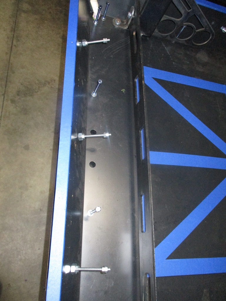
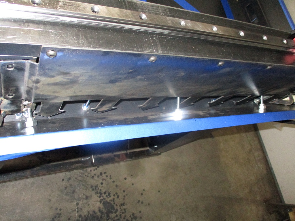
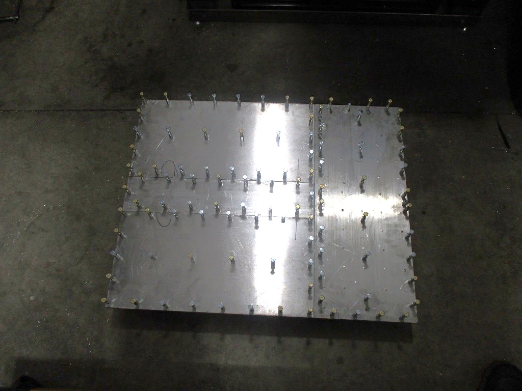
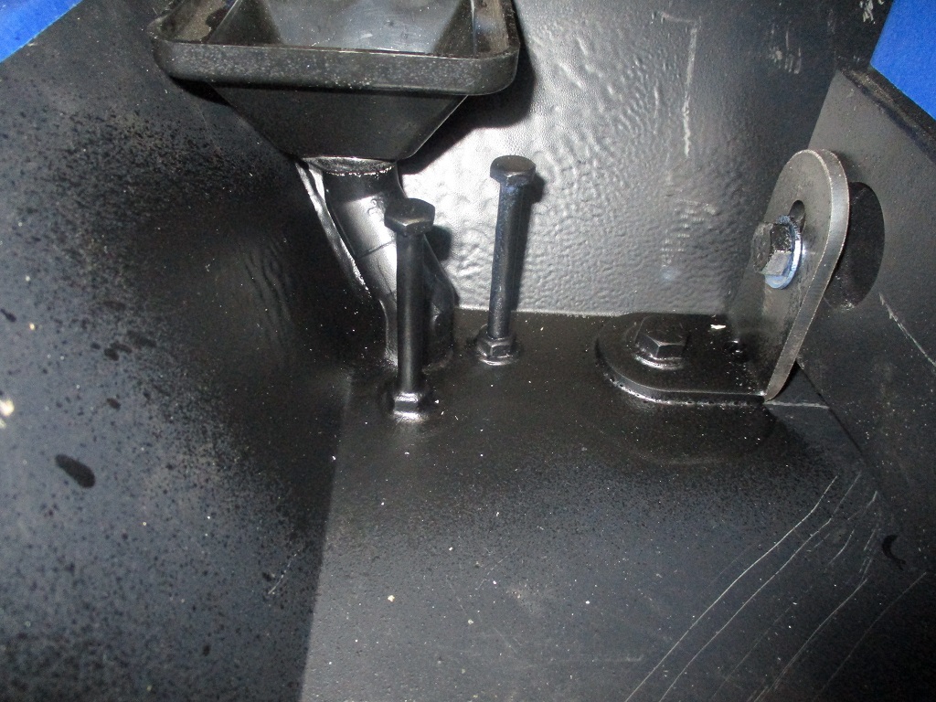
Added 3 more studs on each of the sides of the pan to help lock the pan to the concrete slab. Just some 3.5" long carriage bolts:
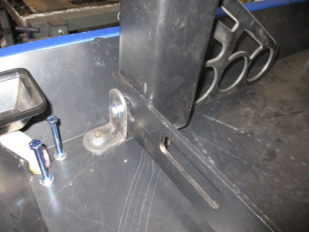
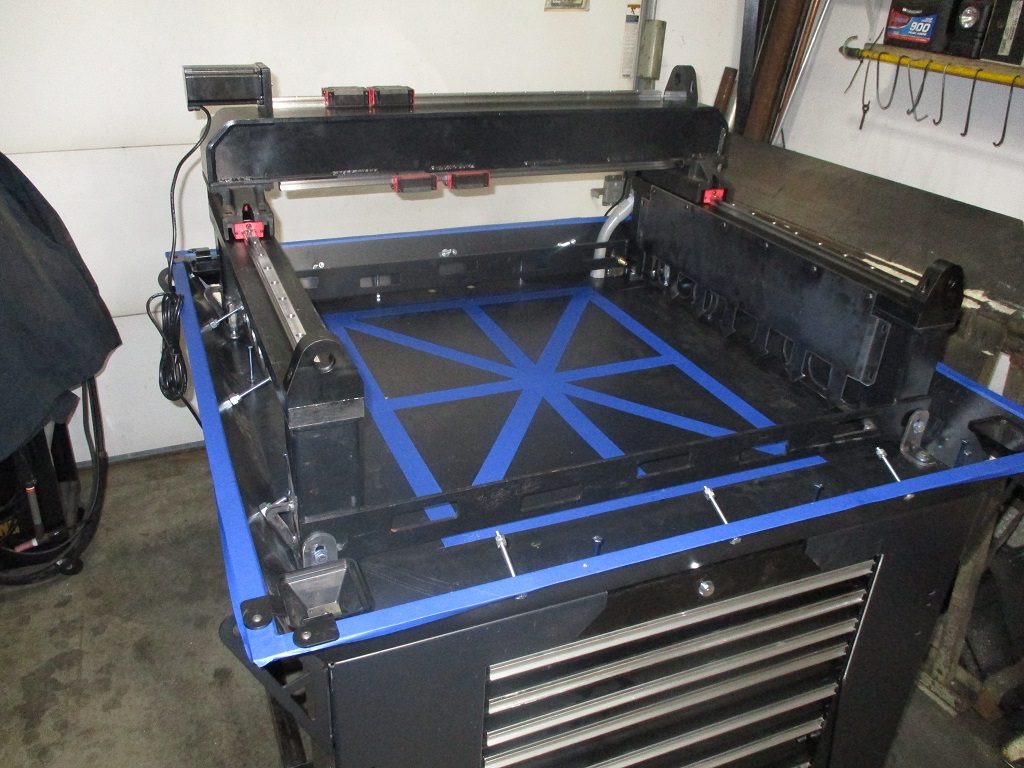
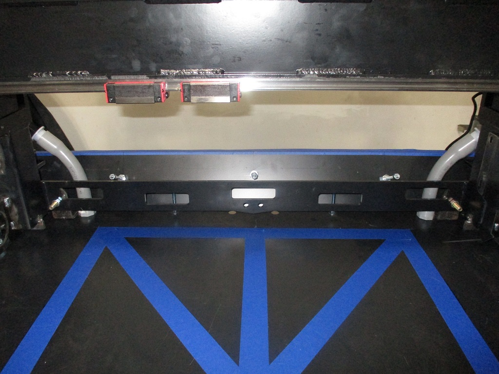
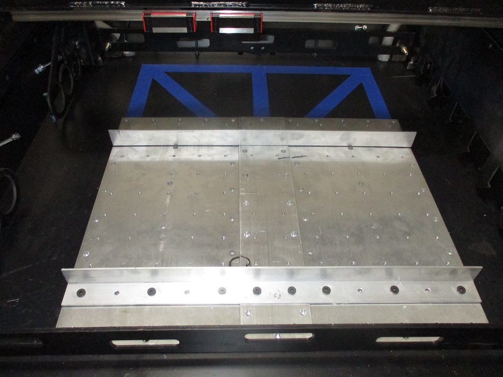
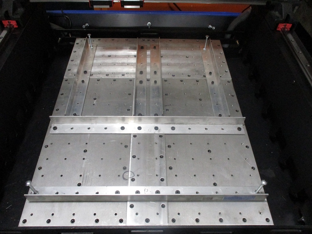
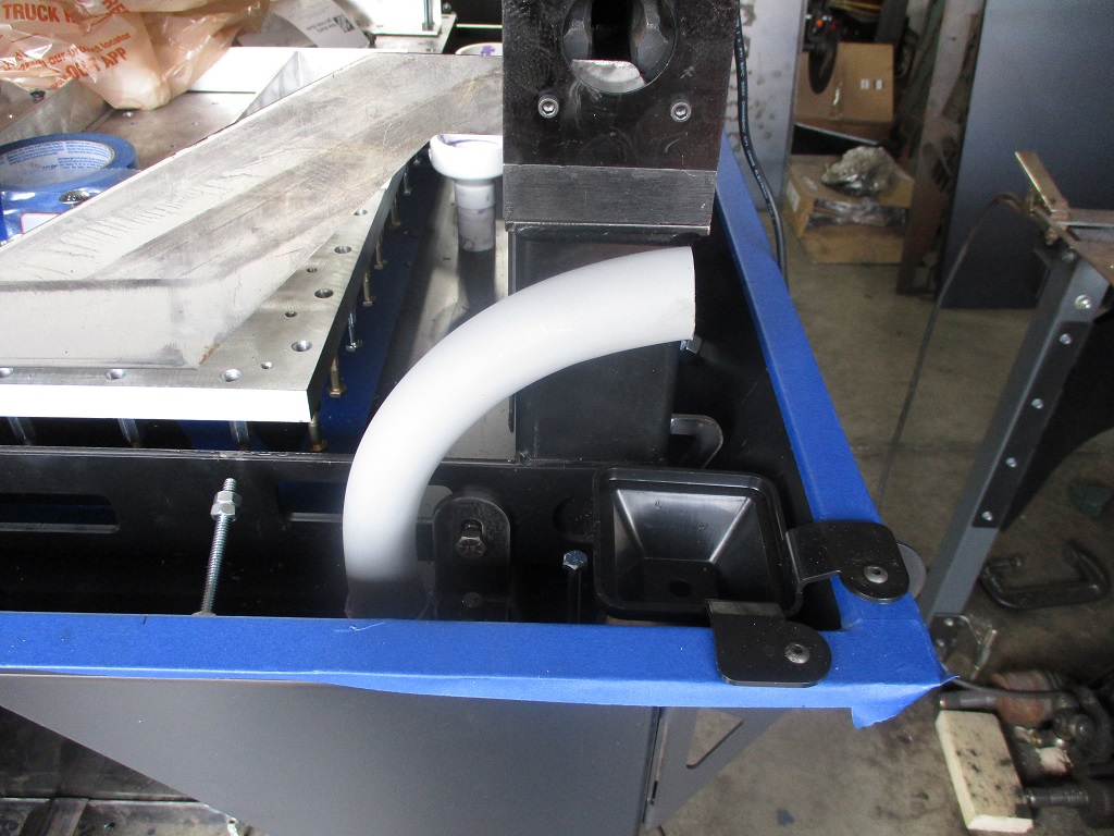
Then I started mocking up the Y and X rails primarily to start thinking about how I am going to run the cables. I was able to move the X-rail up and back the length of travel of the y-rail with my pinky finger. The blue tape in the center is my planned oversized 24x30 base plate.
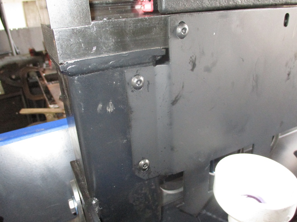
For the Y-motors, all cables will be routed through some PVC conduit under the motors and through the concrete base. I need up upsize at least the left side to 1" from 3/4" so that I can run the X rail cables through it as well. In this picture you can also see the bracket that holds the rear of the Y-rails (one per side).
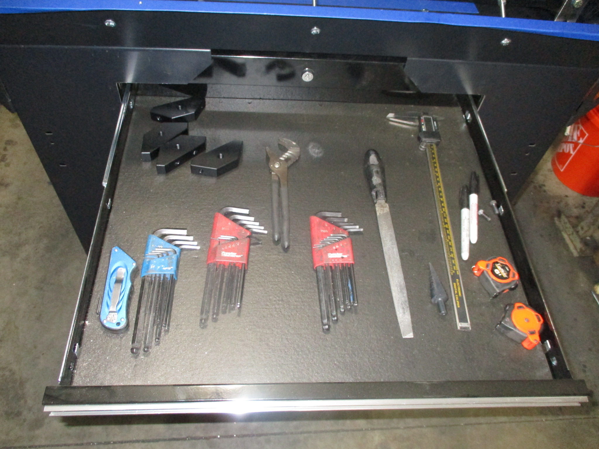
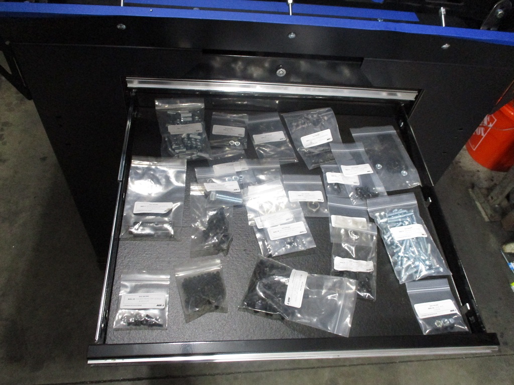
The tool box is already coming in handy…
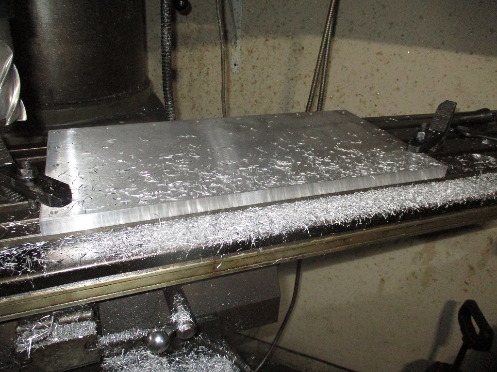
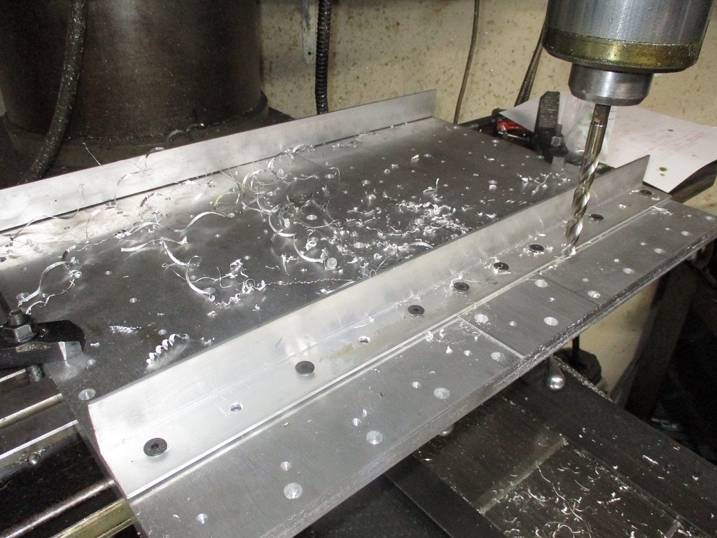
Started working on the oversized base plate. First thing I noticed was the rough cut perimeter of the base plates was not square with the 2x2 hole pattern, so I put them both on the mill to square all the sides to the 2x2 pattern.
Once they were square, I mocked up the 4" spacer piece and checked the hole centers… and needed to take about 0.095" off in total between the two inside surfaces to keep a constant 2x2 pattern across all the plates. Once that was done, everything was bolted/clamped and started drilling out the pattern on the 4" center plate. Once I had some locating holes for the 4" center plate and bolted it into place, I trued up both ends.
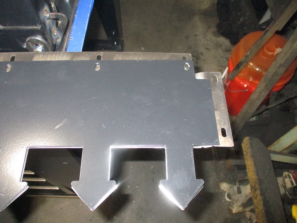
Here is the front portion of the enlarged baseplate setting in the pan. I need to do the same work to the 24x10 plate for the rear.
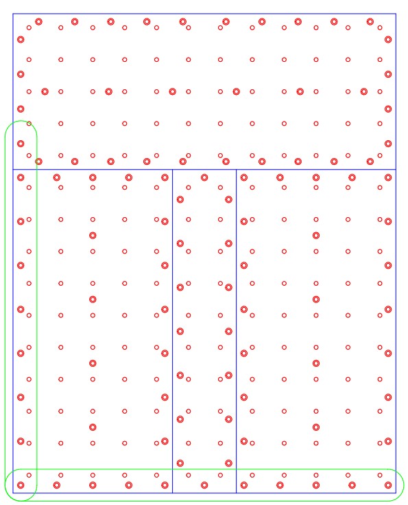
I did change up the anchor pattern on the 4" and 10" plates in my drawing. Originally the anchor pattern was mirrored from the current plates, but then I thought the anchors would be too close and might get hung up on the concrete rocks. So I offset them to increase the spacing between anchors.
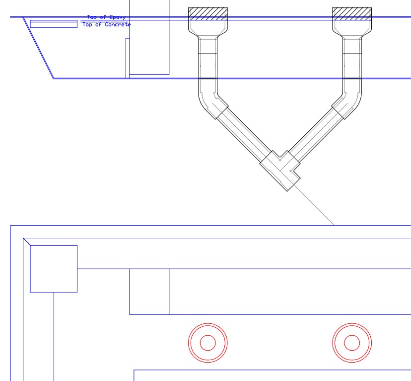
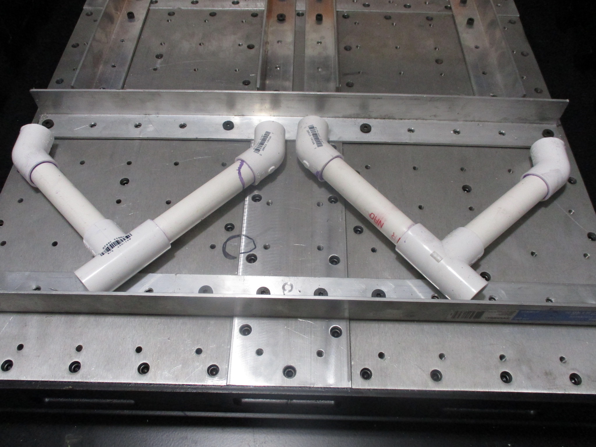
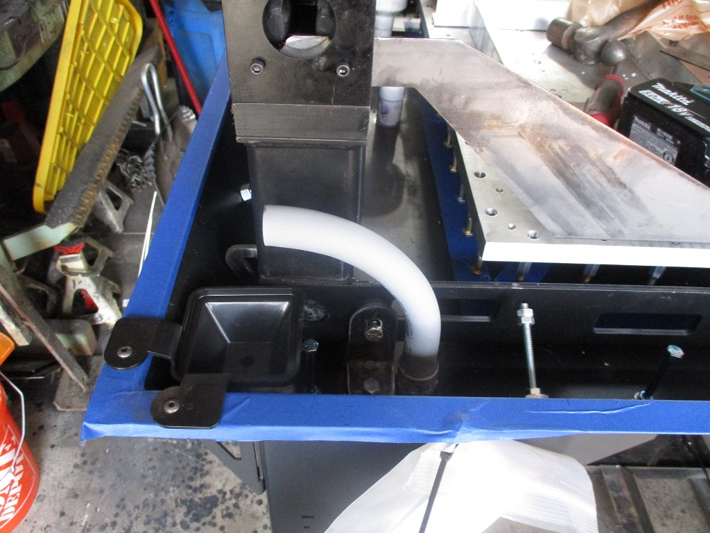
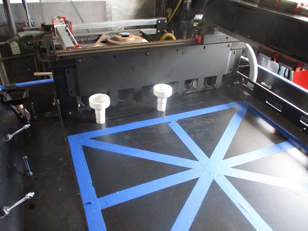
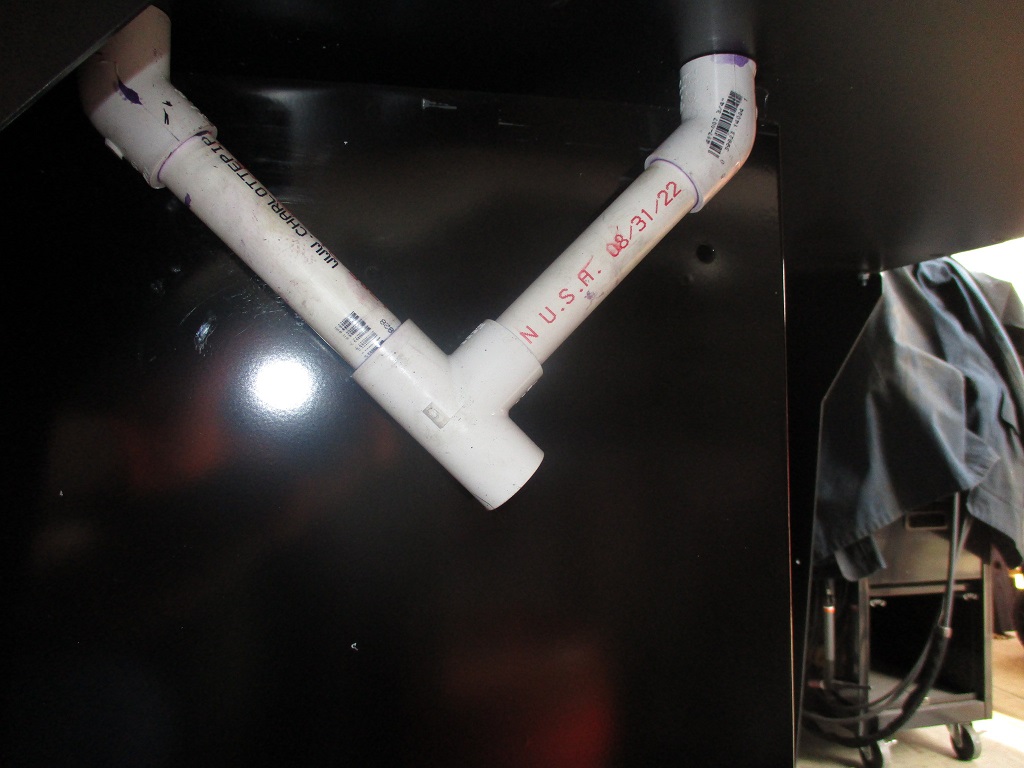
Finished up the cable PVC tubes. Kept the 3/4" on the right, but switched to a 90 and a 1" 90 on the left. The 1" is large enough to feed 3 motor cables through.
Installed the center drains after trimming down the overall height of the 3/4 to 2" reducers.
Drilled an tapped all the extra holes in the new Y-rail side plates.
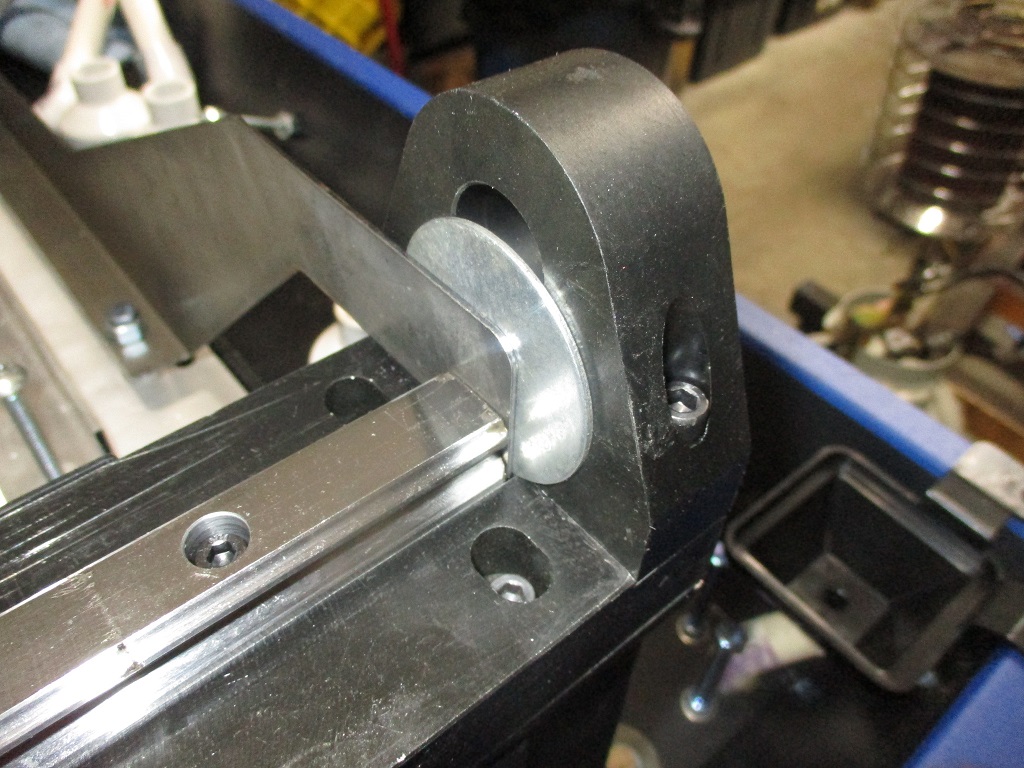
Also figured out how to properly locate the baseplate in the concrete and keeping the 2x2 pattern true to the left Y-rail. Used the supplied Langmuir baseplate brackets, with a 3/4" spacer to account for the raised rails. Then pulled the Langmuir brackets to the right so they are tight to the right side of the left rail. Then installed some bolts, 2x4x6 blocks, and ran a dial indicator down the length. Loosened the bolts holding the Langmuir brackets to the baseplate and squared it up.
While planning for this, I noticed there was room for the Langmuir brackets to fit between the linear rails and the end plates. I used washers to close the gap and doing the placed the front of the plate right at 8 9/16". I did have to offset the rear spacer about 7/8" to make the Langmuir brackets fit the rear gap.
Now it is time to take the top plates of the y-rails back off , reinstall them and make sure everything stays true and will go back together. It need to be able to do this to allow the area between the Y-rail side plates to be filled close to the top with concrete.
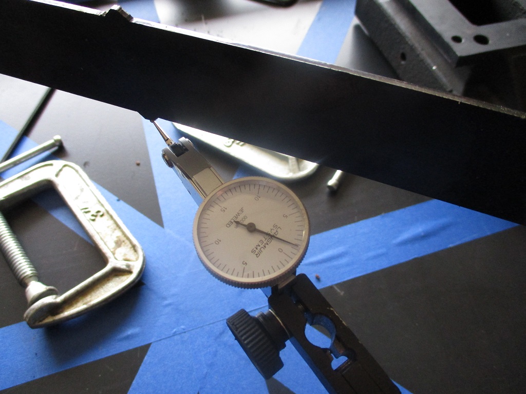
Took the top of the Y-rails off to verify everything stayed in place with them off. Everything checked out and once it was put back together I checked co-planarity and it came out about 0.0013 off between the two 45" diagonal measurements w/o any shims. Looks like my time with the machinist level, the jack bolts and hold down brackets paid off. After the concrete pour I will be able to shim it to get even closer.
Saturday is concrete day! Been thinking a lot about the concrete pour sequence…
I have 15 bags of concrete pharmacy set control to delay the setting on the concrete. I also ordered 10 bags of the concrete pharmacy flow control… but not sure they will be here in time.
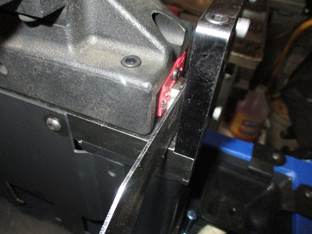
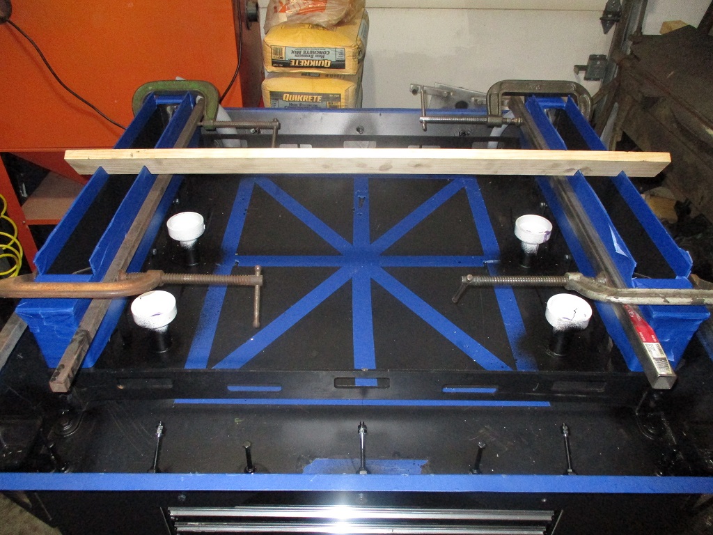
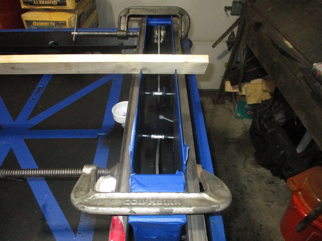
The Y-rails are now opened and taped off to protect them from stray concrete. The bottom has a couple of 1/4" bolts through them to keep them from spreading as the concrete is filled. To keep the top of the panels from bowing out with the concrete I have clamped some tubes to the sides.
The plan is to start the concrete by filling one y-rail at a time. Once the first one is filled, I will install the top Y-rail and all the bolts, then remove the clamped on tubes on the side.
Then do the same with the next Y-rail and install the top rail and remove the clamped on side tubes. Once both top rails are installed, then I will square them up and proceed with the concrete for the center section so I can get the base plate set and positioned early. Once the Y-rails and base plate are set, then I will focus on the corners and edges. This should help avoid any issues with the center setting up before the baseplate is set.
I also wanted to seal around all the drains and bolts in the base to keep any concrete water from seeping out during the pour and cure. I was looking for some Permatex red gasket spray at the parts store, but they didn’t have it, so I picked up a large can of flex seal. It pooled up nicely around all the bolts, tubes and brackets in the pan and should get the job done.
[This message has been edited by fieroguru (edited 03-03-2023).]