I may have asked this before... but is the reason you couldn't make the upper and lower tubes the same length conflict between the upper bolt holes and o-ring grooves?
Originally posted by Trinten: It looks good man... I really hope you aren't about to say they'll be ready for sale in a week or two... I took one of your recommendations from a few months ago and got one of those alternatives!
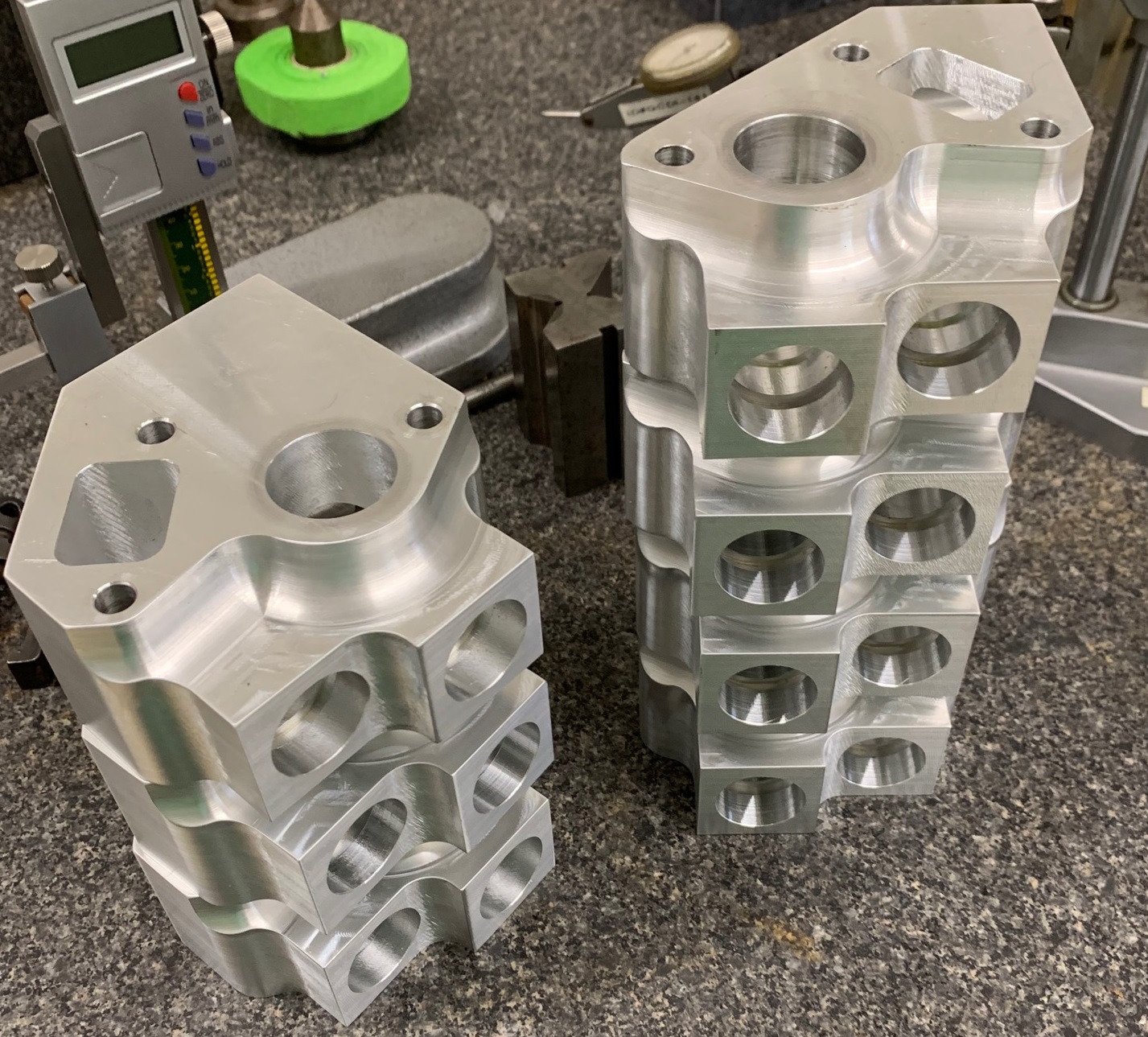
These won't be for sale anytime soon. The CNC shop still has some work to refine to get a better finish on the parts (they have chatter marks and I don't want them too). I also have to verify fitment and then send these out to some lucky people with running LS swaps that are already running an electric water pump for testing (after I smooth them up).
quote
Originally posted by Bob2112: Oh man oh man oh man. I can't wait until these are ready to buy.
Thanks! It will still be several more months at the earliest. The machine shop needs to improve their process and I need to get them testing/validated.
quote
Originally posted by Will: I may have asked this before... but is the reason you couldn't make the upper and lower tubes the same length conflict between the upper bolt holes and o-ring grooves?
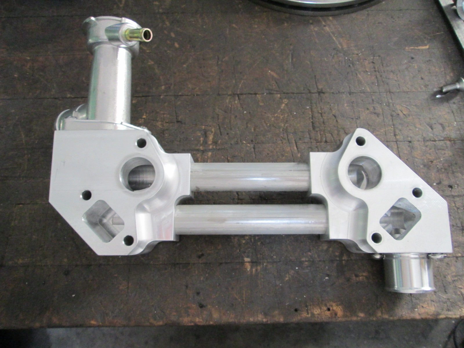
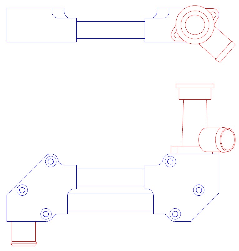
The stepped profile of the tubes is just for looks and lightness. When the blocks were cut flat on the end, they just looked too bulky.
quote
Originally posted by Steel: That looks tremendous... really nice work/design.
Thanks!
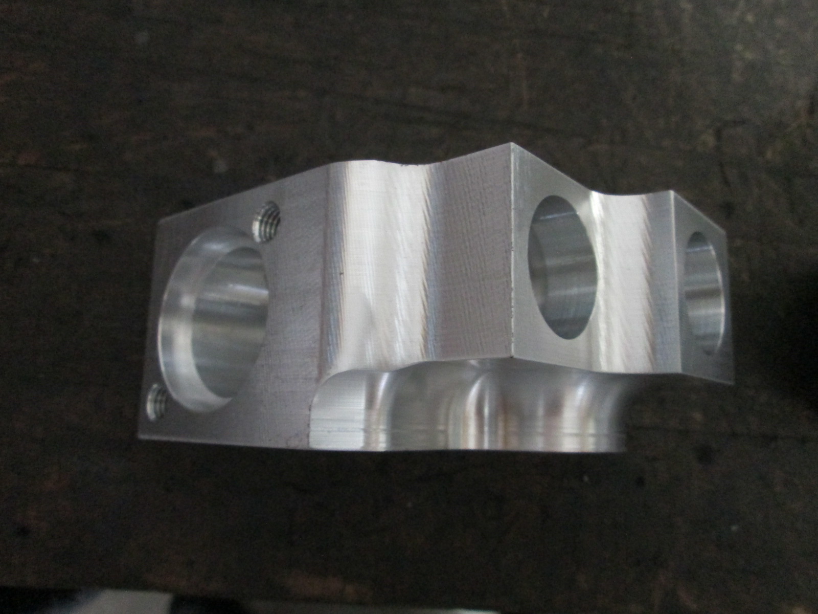
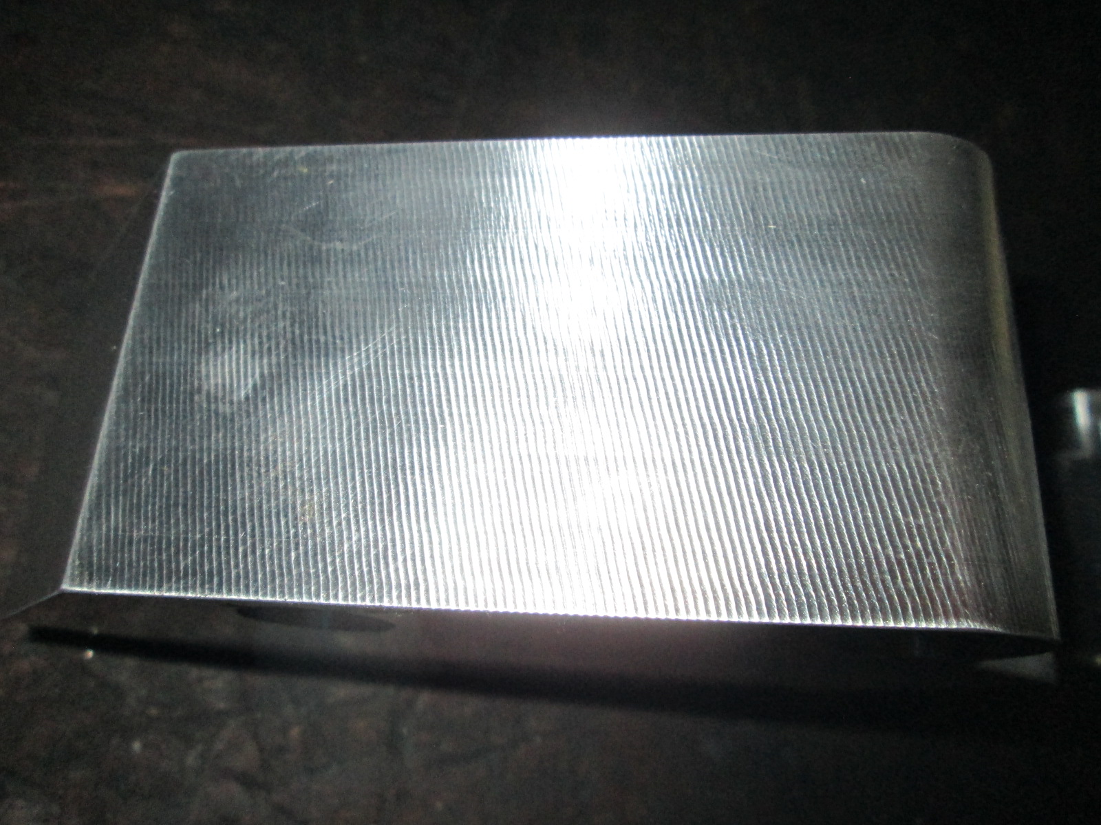
Here you can see the chatter marks that I will sand smooth:
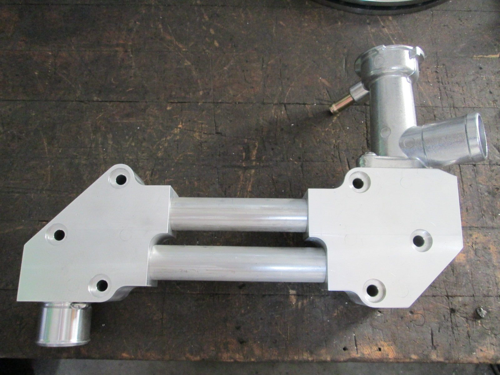
A fully assembled water manifold (I still need to polish the center tube - it is just mill finished):
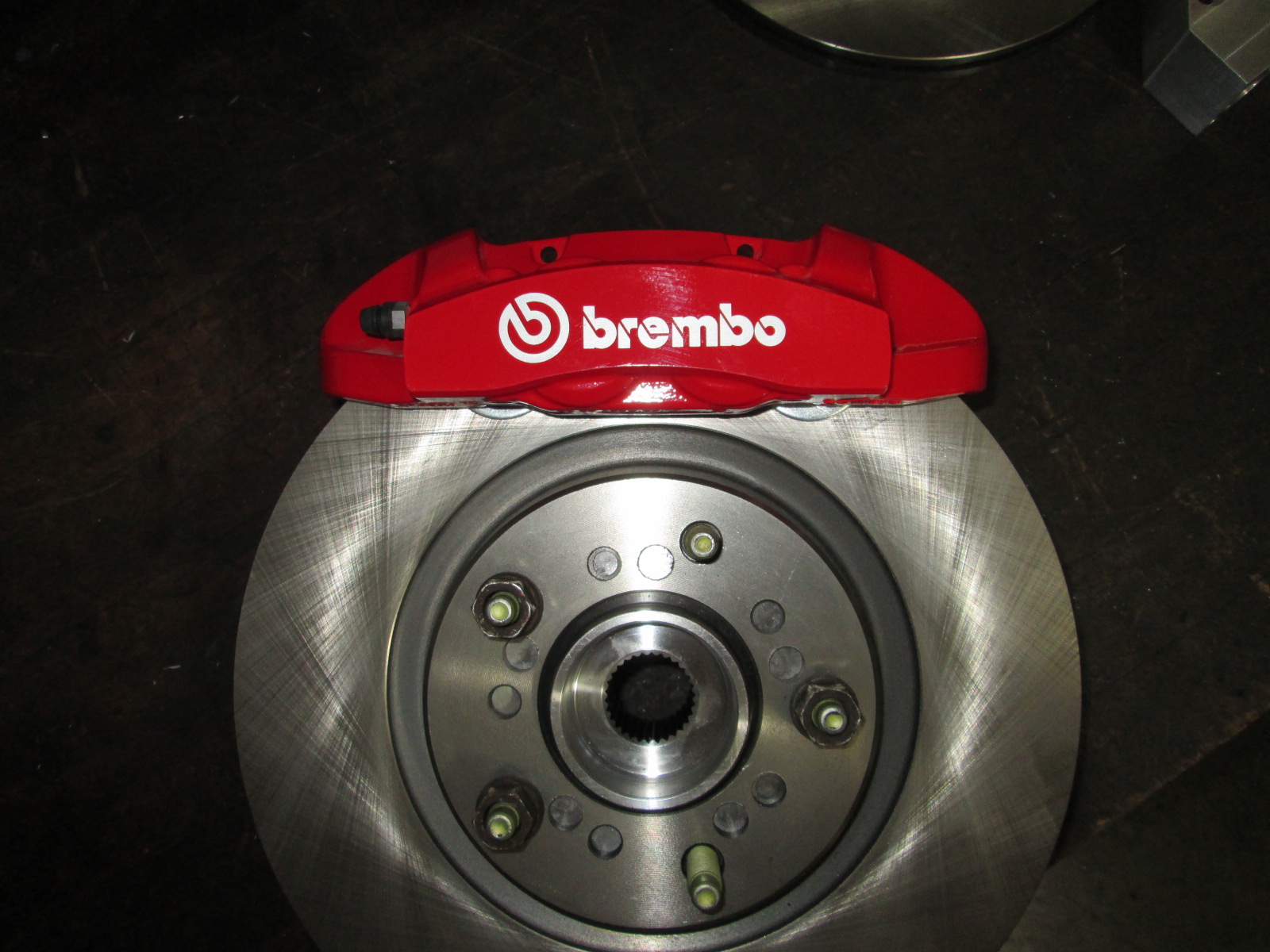
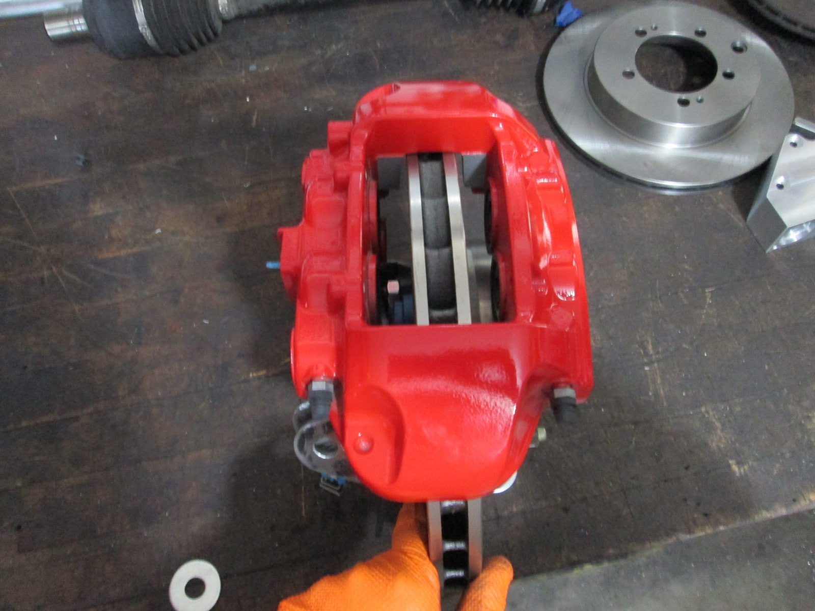
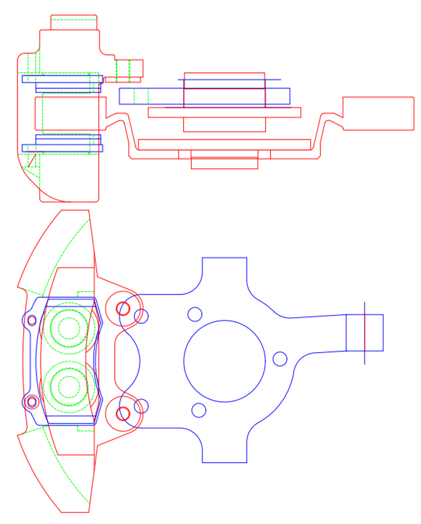
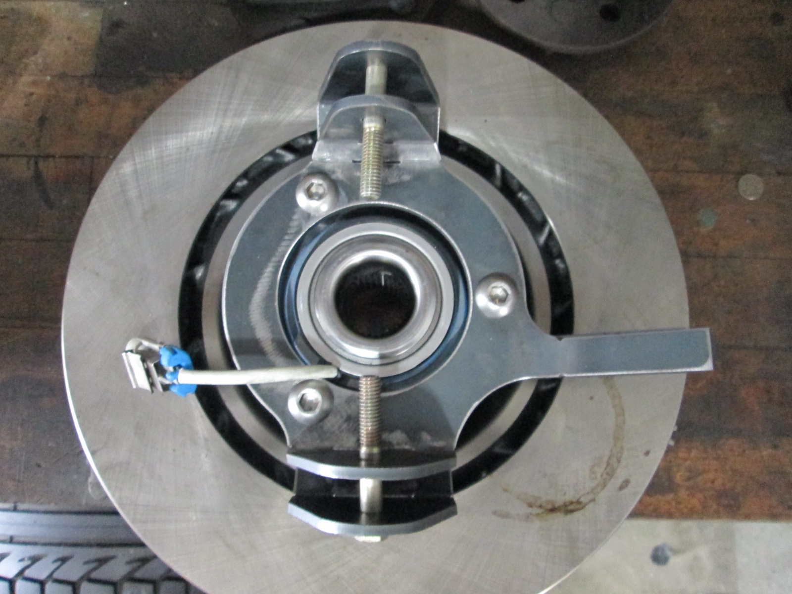
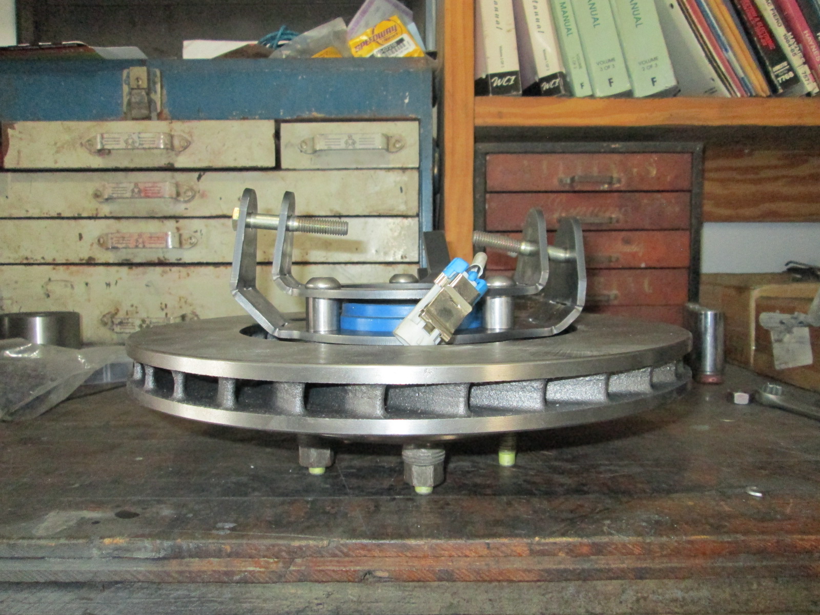
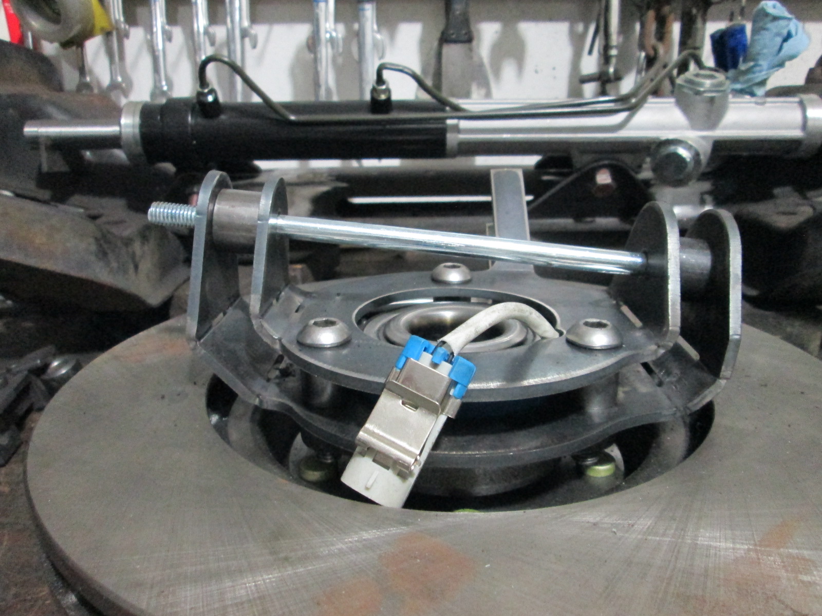
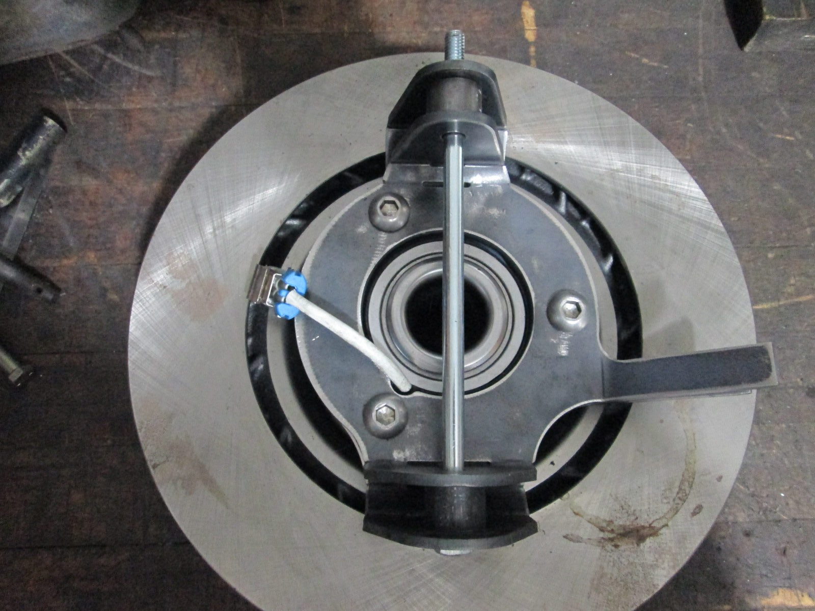
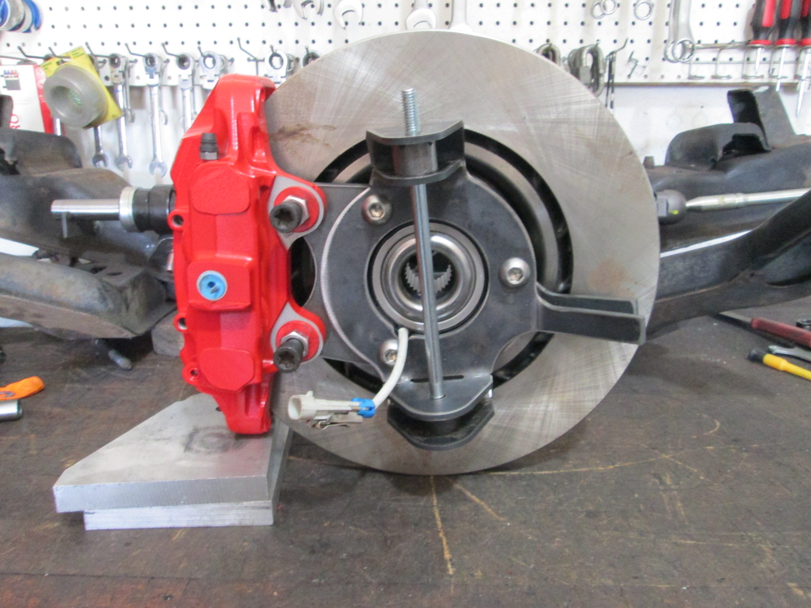
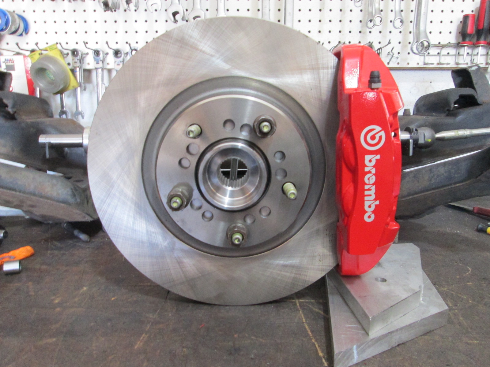
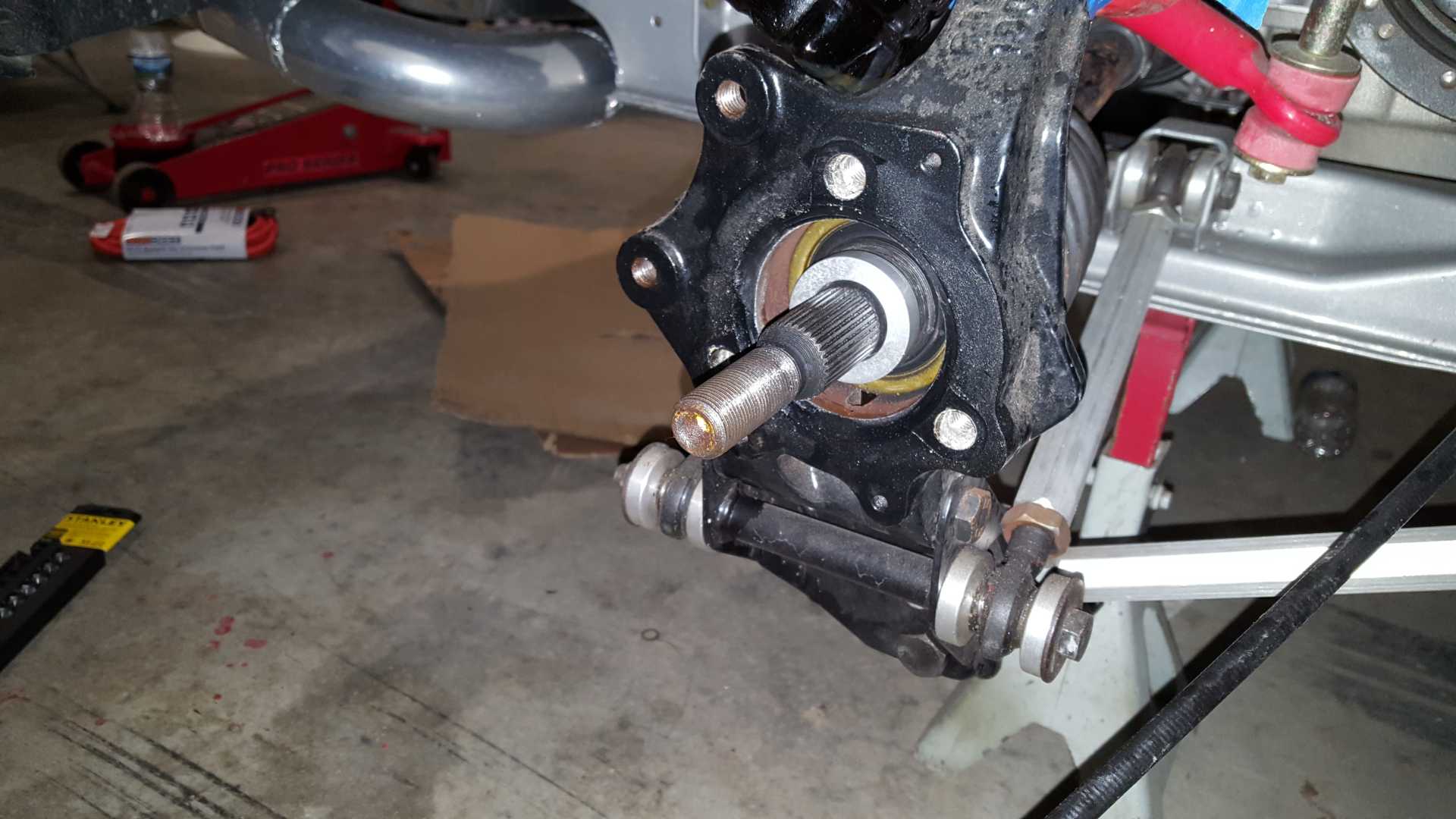
My new Brembo caliper also showed up (it won't stay red...). Looks like there will be just enough room for the brake bracket to bolt to the wheel bearing bolts and have the bolts clear the C5 CV.
Originally posted by fieroguru: Over the last couple of months, I have been working with a local CNC shop to start making several of my parts...and we have finished the redesign of the LS water manifold.
quote
Originally posted by fieroguru:
Thanks!
A fully assembled water manifold (I still need to polish the center tube - it is just mill finished):
Another one I may have asked before... Was there something preventing both connections from being on the forward block? I would expect that would be easier to plumb, since the lower connection doesn't have to make its way around the belt drive.
I thought about mounting the inlet to the forward block, but could not find a good hose connection to mount on the front w/o having issues with the mounting bolts.
The other concern I had with that is flow distribution between banks. With the inlet and outlet on the same side, the easiest flow path would be in and out that forward bank and might bias that bank. With the inlet and outlet on opposite banks, any inherent flow restrictions in the manifold are largely balanced.
My new Brembo caliper also showed up (it won't stay red...). Looks like there will be just enough room for the brake bracket to bolt to the wheel bearing bolts and have the bolts clear the C5 CV.
Any chance we can convince you to make up some brackets to allow those awesome looking Brembo's to bolt up the the stock front/rear spindles??? Those would look great with your 13" rotors already drilled for the 5x100 pattern.
Originally posted by qwikgta: Any chance we can convince you to make up some brackets to allow those awesome looking Brembo's to bolt up the the stock front/rear spindles??? Those would look great with your 13" rotors already drilled for the 5x100 pattern.
quote
Originally posted by fireboss:
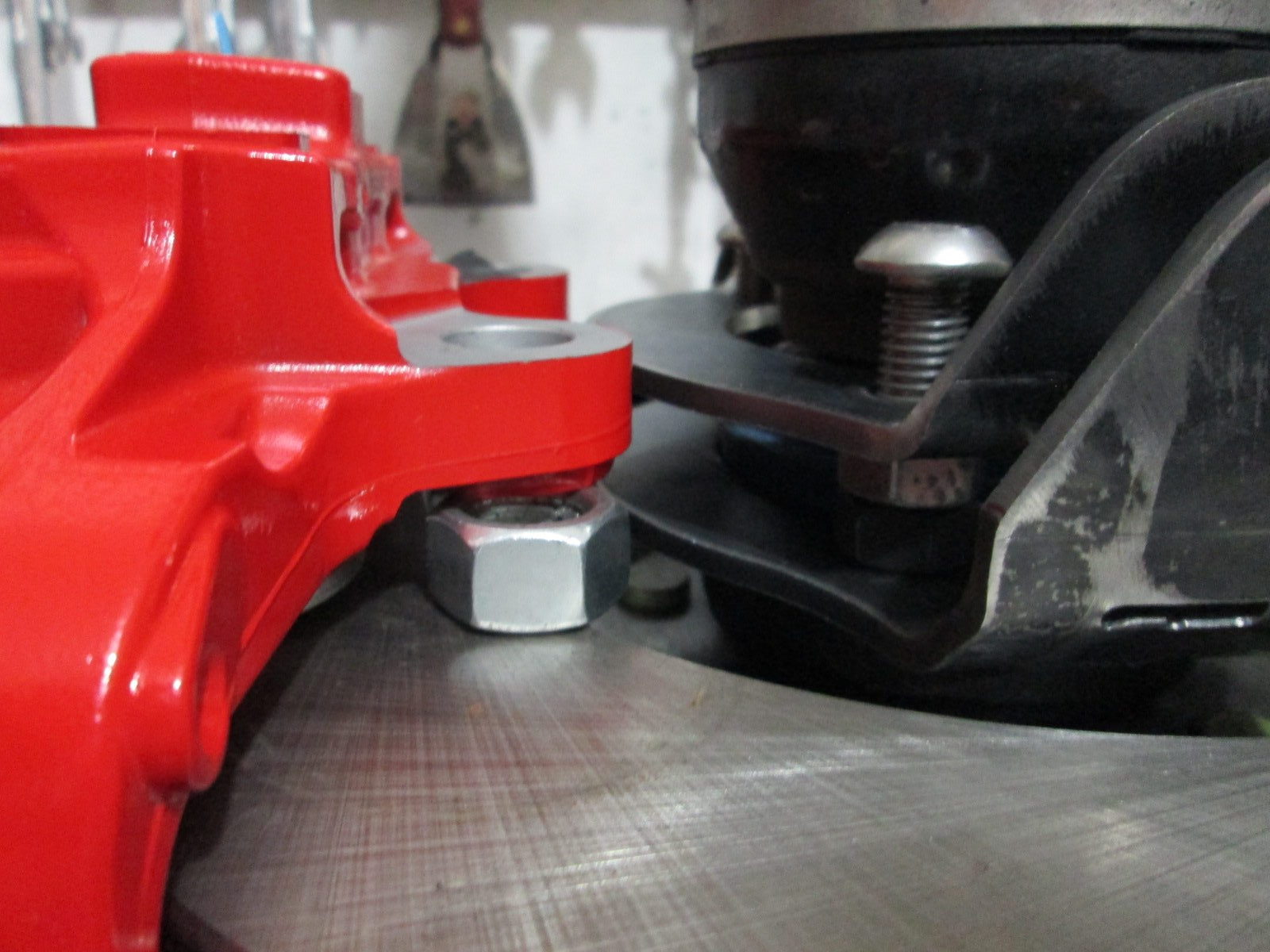
Sadly, I haven't even tried to mock them up with the stock knuckles... I do know the Brembo calipers will not fit my current 13" rotors, but they will fit the 12.8" rotor shown, and this rotor does fit the stock 88 knuckle.
Edit... I was able to move some of my AutoCAD geometry around and put the Brembo caliper on an 88 knuckle with the 12.8" rotor. There are a few challenges, but nothing is a show stopper yet. The Brembo will need the pressed in threaded sleeves removed to allow the adapter plate to be of sufficient thickness. Length of the bolts will need to be limited unless there is room to rotate the caliper upwards some.
[This message has been edited by fieroguru (edited 08-22-2021).]
I am on vacation for the next week - originally it was to take the Fiero on the 2021 HRPT, but it isn't anywhere near ready. So I get to spend the week working on it. Friday the HRPT is 4.2 miles from my house, so I will spend that day looking at all the cool cars. This also means the HRPT in 2022 should start in my town as well...
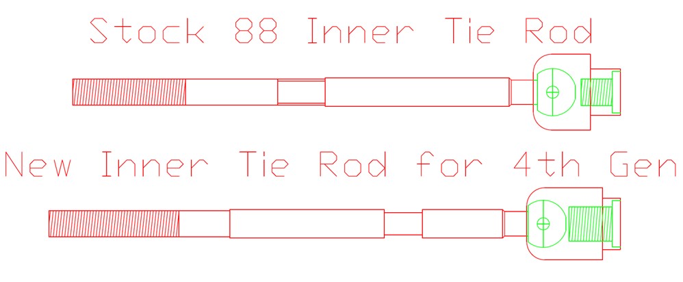
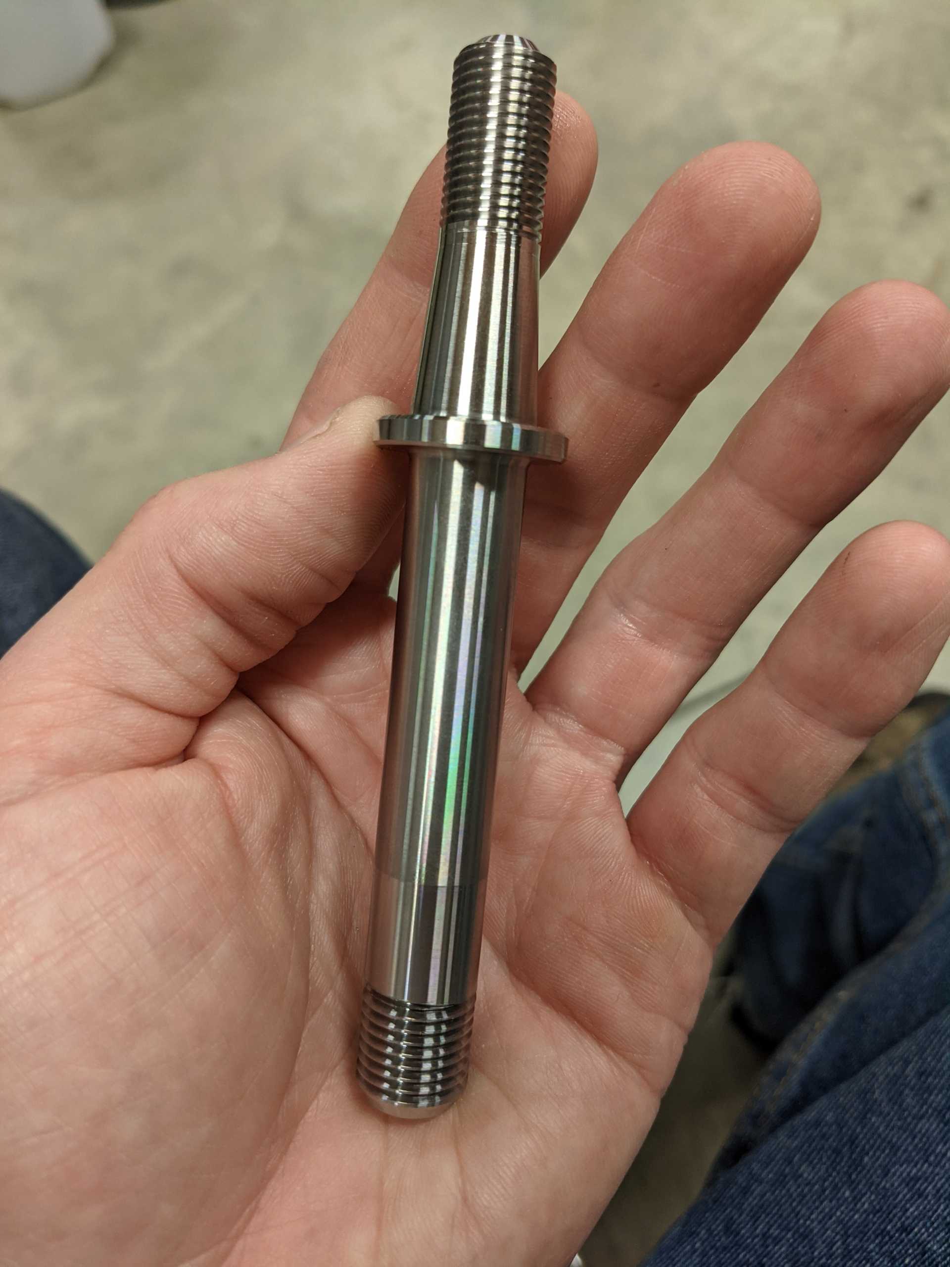
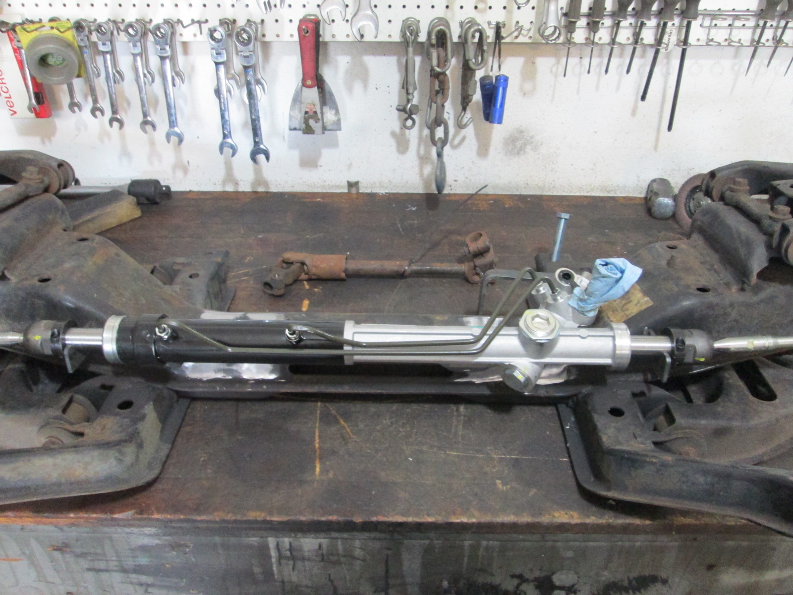
Had some scope creep while thinking about dialing in the front knuckle tie rod placement... Gen 4 Camaro 2.25 steering rack for quicker steering ratio than the 3.38 88 Fiero rack.
The Gen 4 rack is narrower than the 88 rack, has about 4.70" of travel vs. 5.06", and uses female M18 threads vs male M14 threads at the end of the rack.
The travel is a non-issue as the passenger side has a 1.3" deep recessed bore before the seal that allows the rack to have more travel when the inboard tie rod is spaced out. The inner tie rod I found makes it easy to address the width issues and the thread differences. The trick is the inner tie rod has M18 female threads as well, so just a length of threaded rod and some simple spacers will get everything in the right position... no custom machined parts needed.
Here is the comparison between the stock inner tie rod and the one I found for the 4th Gen rack:
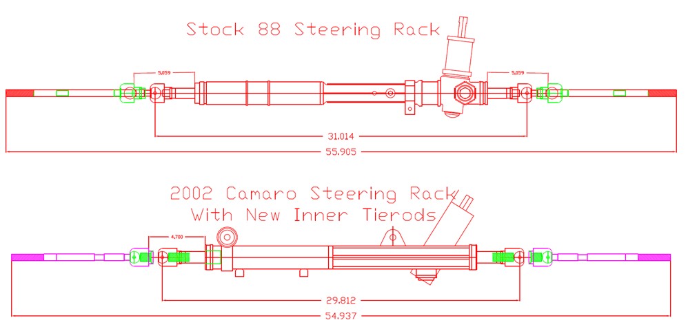
Here are the two racks.
Notice that with the new inner tire rods, the inner pivots are about 1.2" different and the total lock to lock distance at the outer ends is also within 1". The current plan is to shim the passenger side about 0.3" to get the full 5" of travel, then put the about .9" on the driver side so there will be more clearance of the steering tube and the frame rail.
[This message has been edited by fieroguru (edited 08-21-2021).]
That looks like it would increase the radius of the arc (spindle to steering rack connection) on either side, which would reduce bump steer changes. Only possible issue might be the taper for an 18mm tie rod matching the one on the spindle. Or you could always go this route and use a heim joint. Would let you adjust the bump steer directly, and account for lowering the ride height about an inch. Hopefully the picture works.
Actually, it is. Bump steer is the movement of the X component of the arm during a given amount of travel (typically 1"). More X movement equates to toe in or out (depending on whether the connection is forward or rear of the spindle ball joints). This picture makes it pretty clear.
I haven't done the math on how much difference it would make on his setup yet, but any difference the length of the arm makes is less important than getting the arms closer to level and minimizing it in the first place, or toeing out on the front.
Edit: Decided to draw my own picture. Stuff found on the internet generally sucks.
[This message has been edited by SRF13 (edited 08-21-2021).]
I think what Will is trying to say is that bump steer is a byproduct of the combined pivot locations for the upper/lower ball joints, inner/outer tie rods, and upper/lower a-arm bushings. For any given set of pivot locations changing the overall tie rod length longer or shorter will result in increased bump steer. The length of the tie rod swing arm (between the tie rod pivot points) can't be looked at in isolation, it has to be evaluated along with all the other pivot points.
The issue with any steering rack swap (and keeping the rest of the suspension stock), is the X-Y-Z location of the inner tie rod pivot points vs the stock location. Keep these the same, geometry (including bump steer) will remain unchanged.
I am likely going to do this twice, once for use of all stock suspension parts with a 1" lowered stance and again for my specific application where I am changing just about all the pivot points.
The outer tie rod conversion to rod end allows for elevation changes in the pivot point, but I would rather do all the math and testing up front and build the changes into the design. The end product will be lighter, stronger, and not look like an afterthought.
[This message has been edited by fieroguru (edited 08-22-2021).]
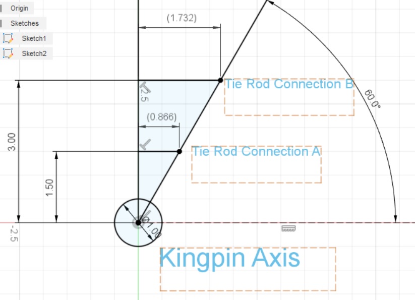
Agree with almost everything you said. Keeping the outboard connection points unchanged and changing the steering rack alone (that results in a longer arm) was the case I was talking about with my above posts. That's the case that it appeared you were detailing with your picture. If the different rack with longer arm is the same height and fore/aft location as the stock one, the resultant rate of change in bump steer will be less. Bump steer is the rate of change of toe for a given amount of suspension travel. In the end, that rate of change is dependent on 2 major factors: 1. Rate of change in the X component in the outboard connection This is dependent on 2 factors itself; mainly where in the arc the arm starts (picture below) and how long the arm is (my previous post picture) 2. How far (fore/aft) from the kingpin axis the tie rod connection is This is really only applicable when changing/redesigning the spindle. Attached picture shows this (looking down at the connections from above)
Regarding what you're doing; designing it out is definitely the best choice and is all that's needed in nearly all cases. Having an adjustment available at the outer end (like the adapter I posted) is mainly only applicable to track cars.
Actually, it is. Bump steer is the movement of the X component of the arm during a given amount of travel (typically 1"). More X movement equates to toe in or out (depending on whether the connection is forward or rear of the spindle ball joints). This picture makes it pretty clear.
I haven't done the math on how much difference it would make on his setup yet, but any difference the length of the arm makes is less important than getting the arms closer to level and minimizing it in the first place, or toeing out on the front.
Edit: Decided to draw my own picture. Stuff found on the internet generally sucks.
Bumpsteer is much more complex than this. The zero bumpsteer condition happens when the line extending the tie rod intersects the instant center created by the control arms throughout the entirety of suspension travel. This is very difficult to build and minor changes, like aligning the suspension to different caster angles, can throw it off. Bumpsteer does not come simply from the arc of the steering arm. It comes from the *difference* between the arc the steering arm traces and the arc the tie rod boss on the knuckle wants to trace.
quote
Originally posted by fieroguru:
I think what Will is trying to say is that bump steer is a byproduct of the combined pivot locations for the upper/lower ball joints, inner/outer tie rods, and upper/lower a-arm bushings. For any given set of pivot locations changing the overall tie rod length longer or shorter will result in increased bump steer. The length of the tie rod swing arm (between the tie rod pivot points) can't be looked at in isolation, it has to be evaluated along with all the other pivot points.
The issue with any steering rack swap (and keeping the rest of the suspension stock), is the X-Y-Z location of the inner tie rod pivot points vs the stock location. Keep these the same, geometry (including bump steer) will remain unchanged.
I am likely going to do this twice, once for use of all stock suspension parts with a 1" lowered stance and again for my specific application where I am changing just about all the pivot points.
The outer tie rod conversion to rod end allows for elevation changes in the pivot point, but I would rather do all the math and testing up front and build the changes into the design. The end product will be lighter, stronger, and not look like an afterthought.
I was starting to say that some additional education needs to take place
The small favor the geometry gives hot rodders with regard to steering rack swaps is that bump steer is much more sensitive to the elevation of the inner tie rod than it is to the length of the tie rod, and is actually relatively insensitive to the length of the tie rod. A builder can deviate from the original tie rod length by an inch or two without much down side, but he really needs to gnats @$$ the vertical position of the new rack.
BMW E30's with E36 steering racks are a case study in this. The E30 rack mount tabs on the crossmember are wider vertically than the thickness of the E36 rack mount bosses. Using spacers solves the mismatch, but you'd better put them in on the correct side of the rack! Installing the spacers on the wrong side of the rack is immediately obvious the very first time you drive the car. Fortunately, it's easy to fix.
That looks like it would increase the radius of the arc (spindle to steering rack connection) on either side, which would reduce bump steer changes.
quote
Originally posted by SRF13:
Keeping the outboard connection points unchanged and changing the steering rack alone (that results in a longer arm) was the case I was talking about with my above posts. If the different rack with longer arm is the same height and fore/aft location as the stock one, the resultant rate of change in bump steer will be less.
You can not make the blanket statement that a longer tie rod results in less bump steer. Well... you can make the statement, as you did, but it won't be correct. Starting from a zero bumpsteer configuration that I described above, lengthening the tie rod will increase bumpsteer. This happens because the longer tie rod traces a flatter arc than the rest of the suspension.
quote
Originally posted by SRF13:
2. How far (fore/aft) from the kingpin axis the tie rod connection is This is really only applicable when changing/redesigning the spindle. Attached picture shows this (looking down at the connections from above) http://images.fieroforum.co...nnection.jpg
This is Ackerman, not bumpsteer
quote
Originally posted by SRF13:
Regarding what you're doing; designing it out is definitely the best choice and is all that's needed in nearly all cases. Having an adjustment available at the outer end (like the adapter I posted) is mainly only applicable to track cars.
It's almost impossible to "design out" because even alignment adjustments will change bumpsteer a little bit. Having the adjustment available to minimize it after dialing in alignment settings just so is handy.
[This message has been edited by Will (edited 08-22-2021).]
Originally posted by SRF13: If the different rack with longer arm is the same height and fore/aft location as the stock one, the resultant rate of change in bump steer will be less.
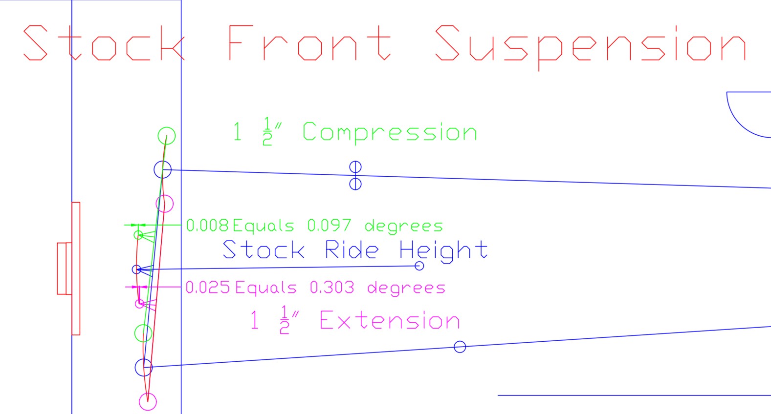
No it is not... especially when we are specifically discussing the 88 Fiero front suspension. There is no need to discuss in generalities, I have the actual measurement data from the change. Here are the actual bump steer numbers for the stock 88 suspension at ride height measured at the outer tie rod pivot for 1.5" of compression and rebound... it isn't perfect, but these are the stock values
All I did here was move the inner tie rod pivot 0.601" inboard, which is what the Gen 4 rack with the new inner tie rod w/o any spacers will do. Notice the bump steer in compression is 50% higher than stock, with much less of a change under extension. The two numbers off to the left are the arc differences due to the longer tie rod link - this is pushing the steering arm out, but the upper and lower ball joints are always getting closer to the chassis at 1.5" compression and rebound, which is why for this application, the longer tie link length Increases bump steer in both compression and rebound.
I will say that the change in bump steer is only about 0.05 degrees, which is very minor, but it definitely isn't in the direction of being an improvement.
[This message has been edited by fieroguru (edited 08-22-2021).]
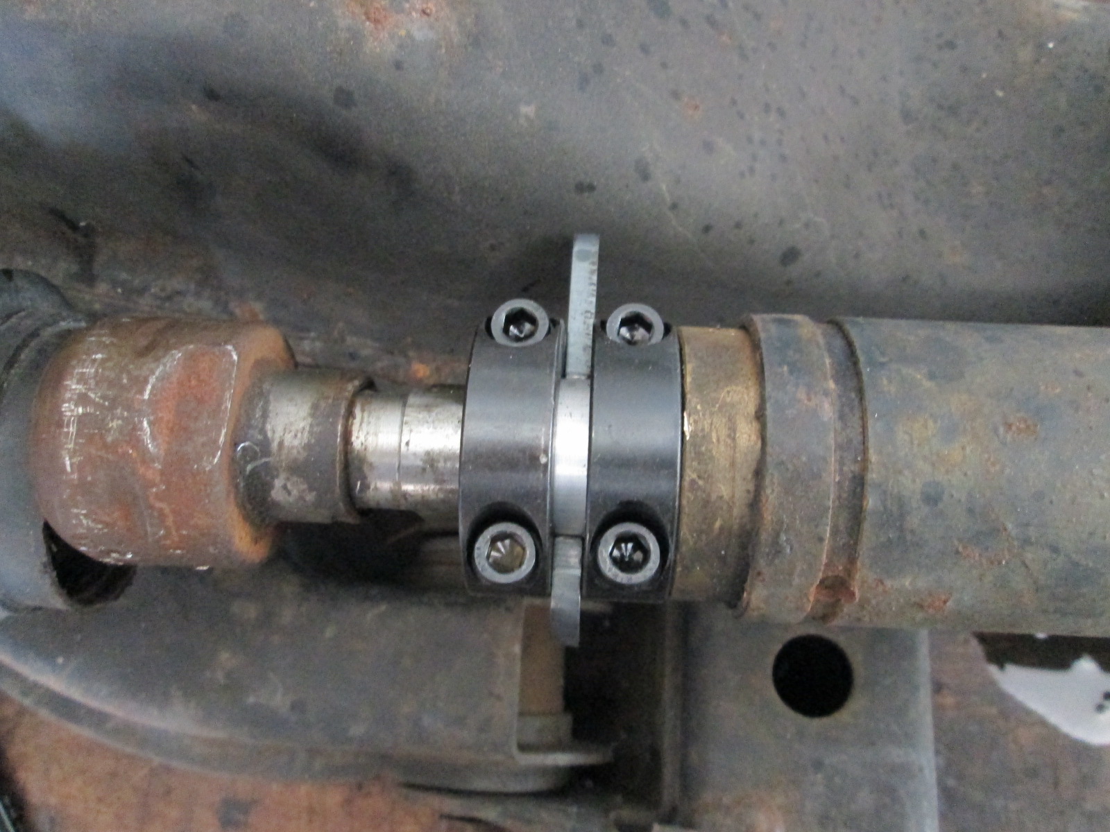
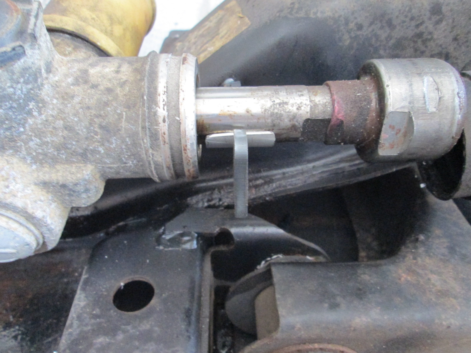
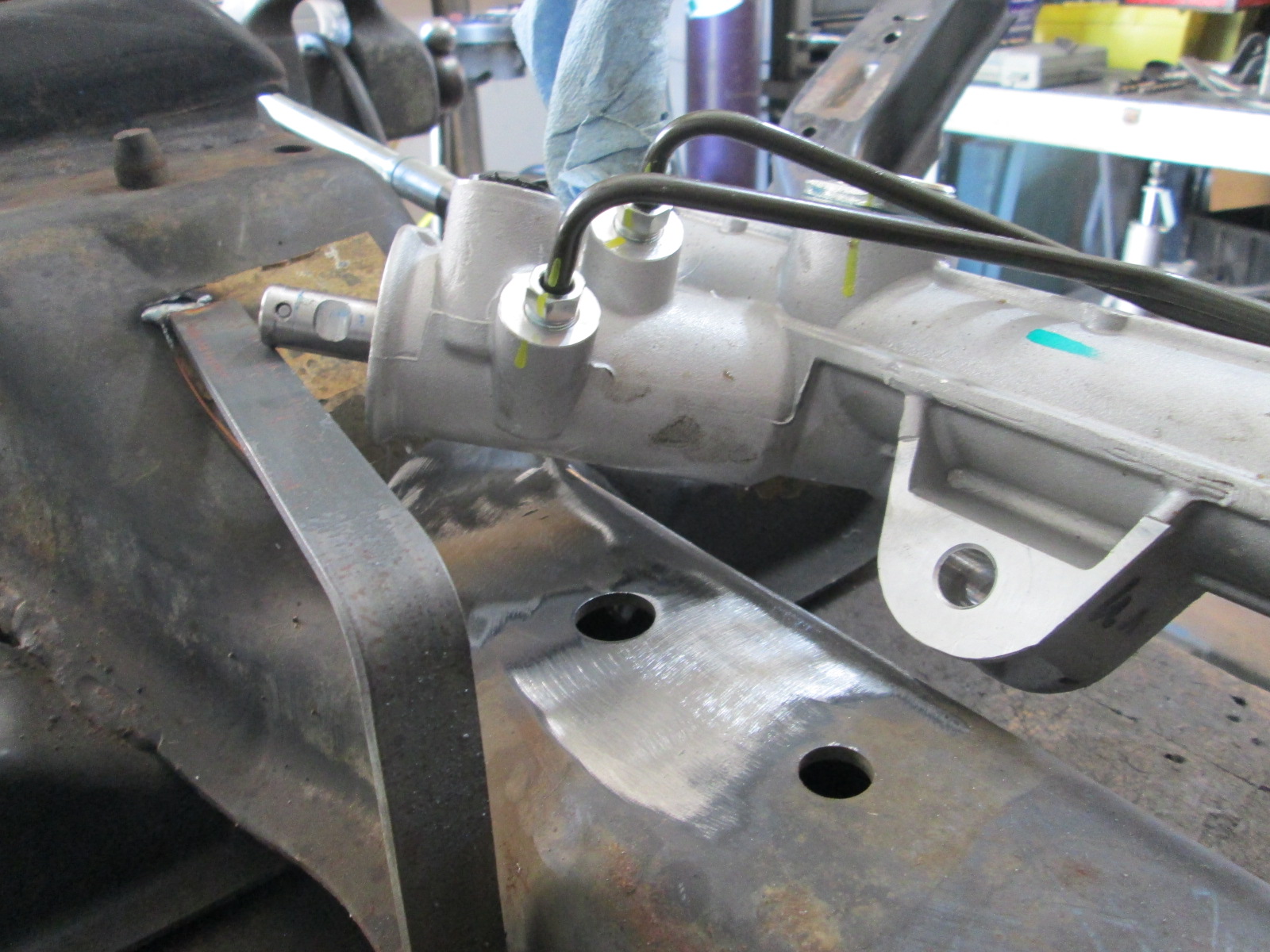
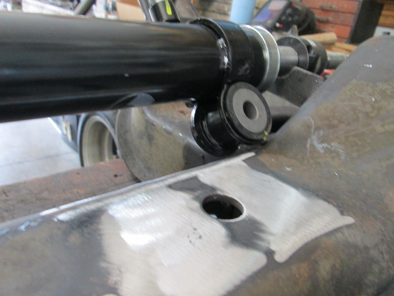
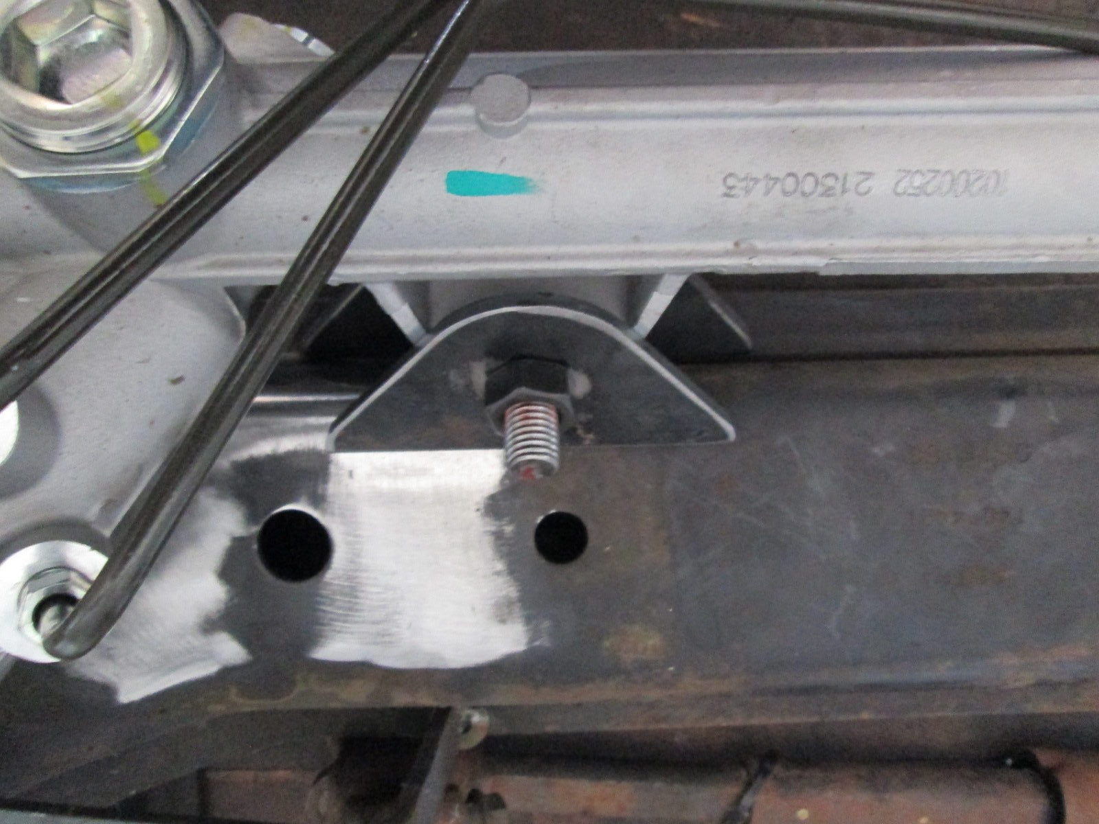
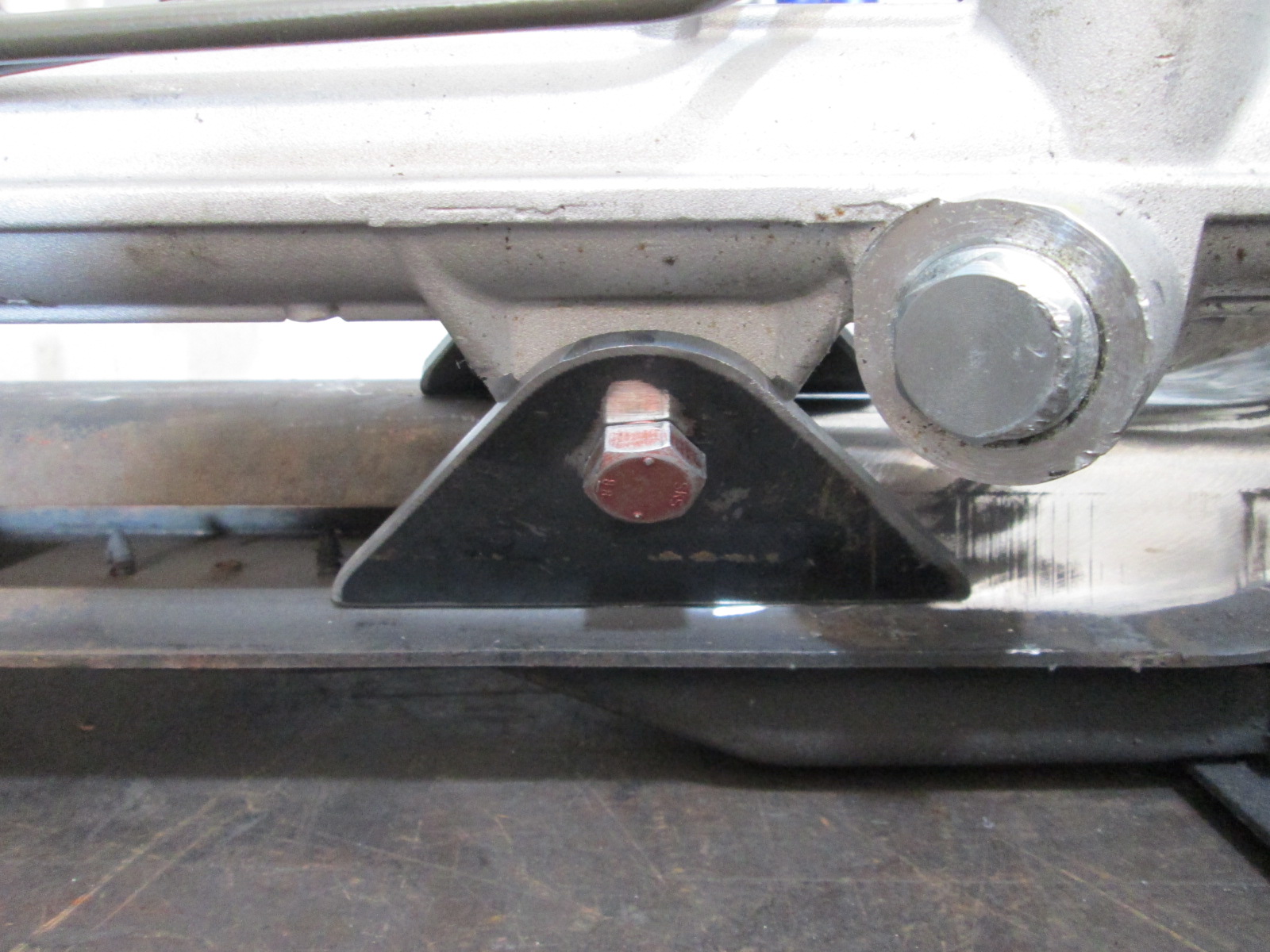
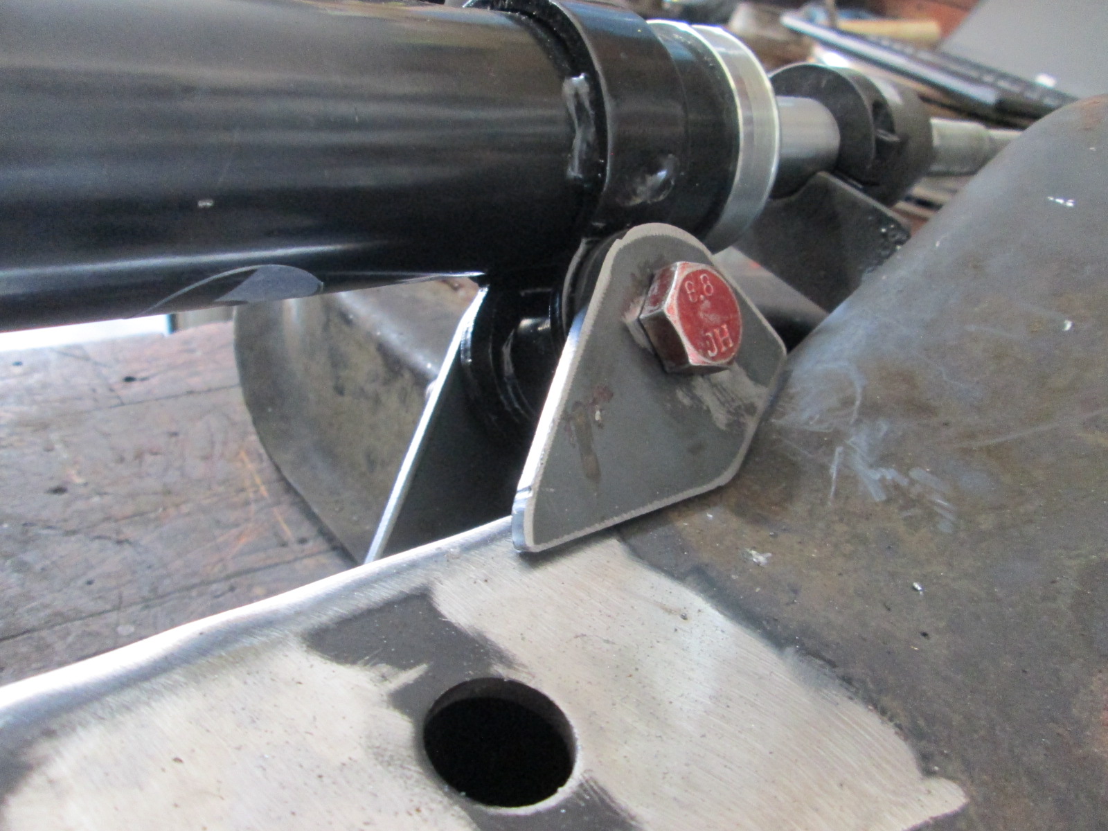
Made some brackets to support the rack as well as define the center point and welded them to the cradle:
The Fiero rack is smaller diameter than the Camaro, so if you use this method, remember to install some shims to account for the larger Camaro rack to keep the center of the rack the same.
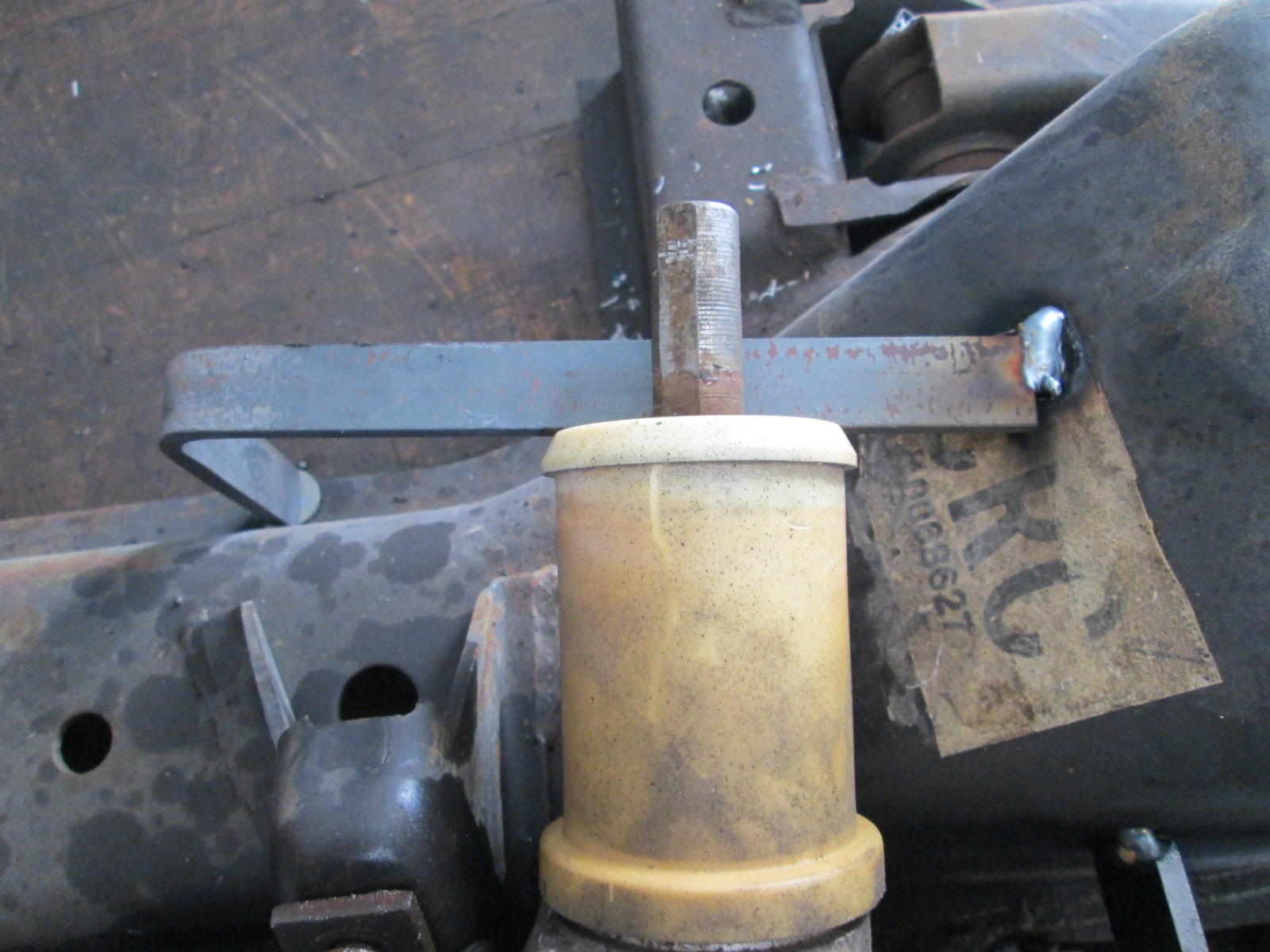
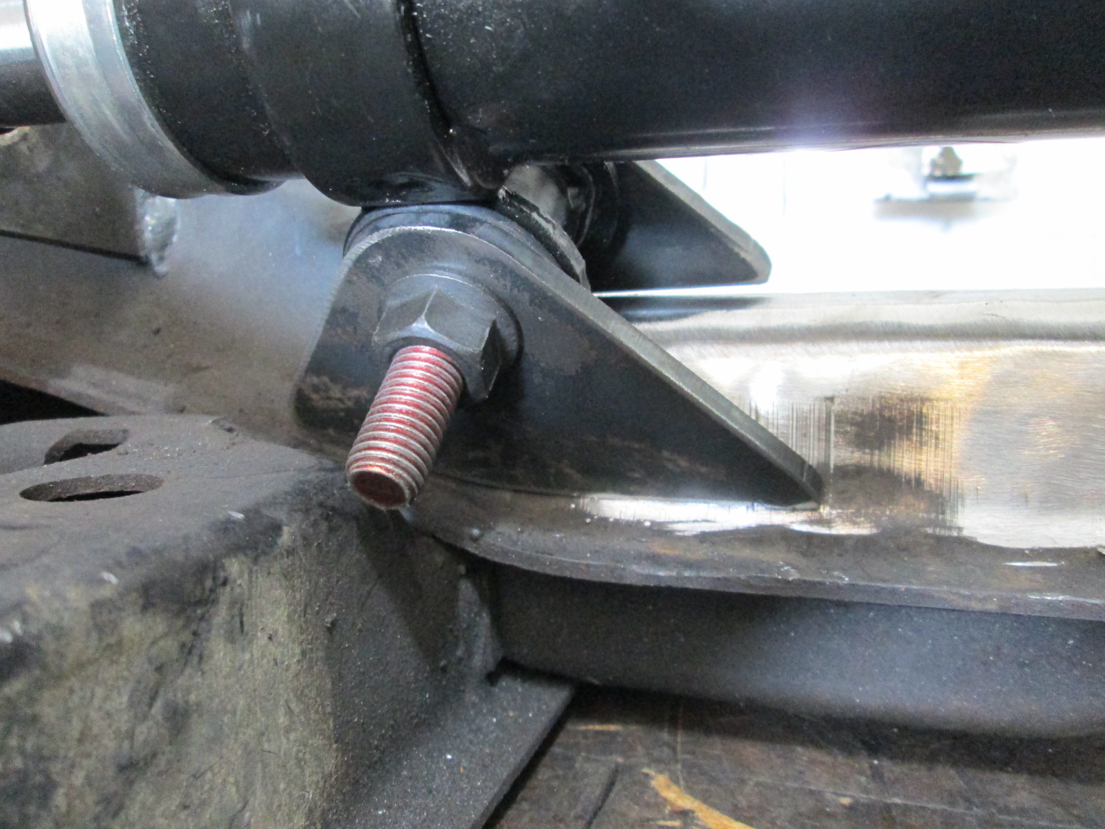
I also put this bar on the back side to define the outlet angle of the rack:
Took the Fiero rack off and first failed test fit of the Carmaro rack... Driver side Fiero rack mount in the way, so I took both mounts off.
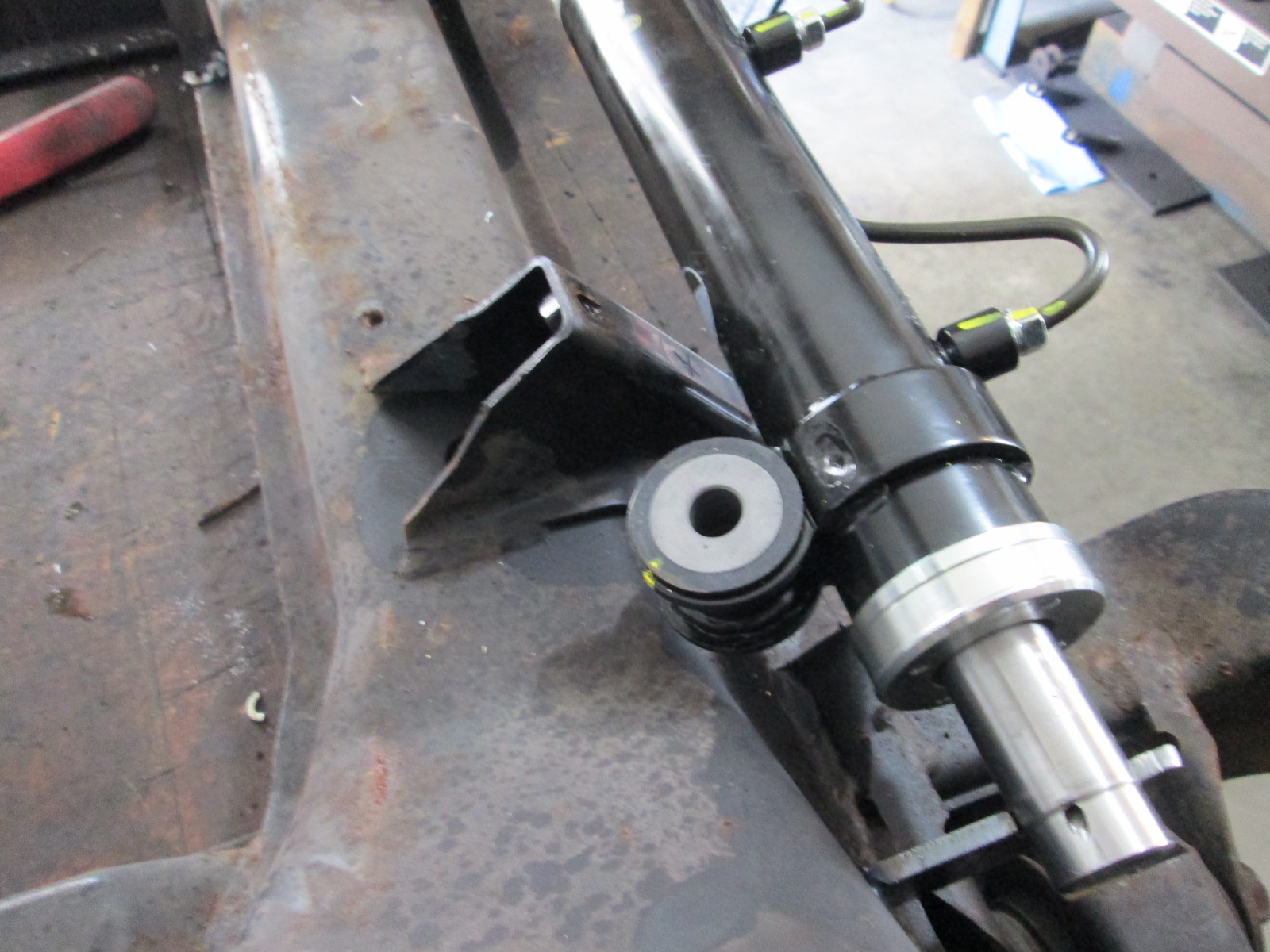
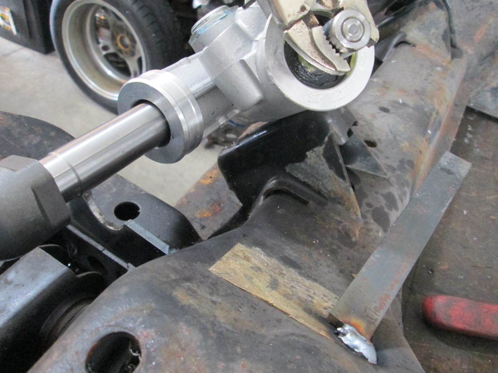
That allowed the Camaro rack with the OEM inner tie rods - these will not be used, to be set on the locating brackets.
Still waiting for my M18 bolts to show up so I can hack them up... but I have plenty of other things to work on until they arrive.
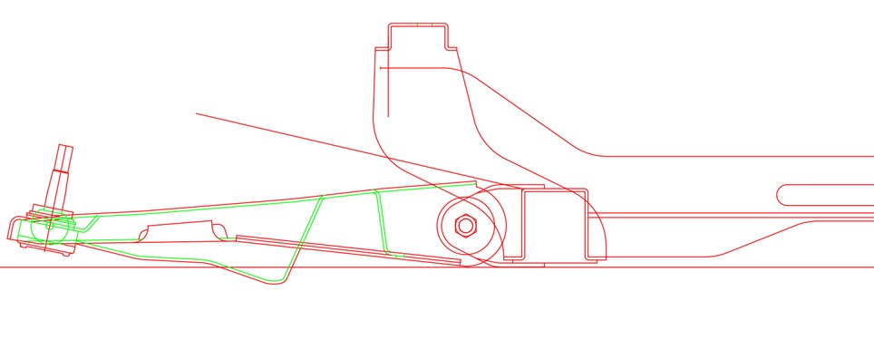
First draft of the rack brackets is done. I need to lock in the side to side rack placement to fine tune the passeger side brackets, but at this point is is simply a matter of shifting geometry in the file.
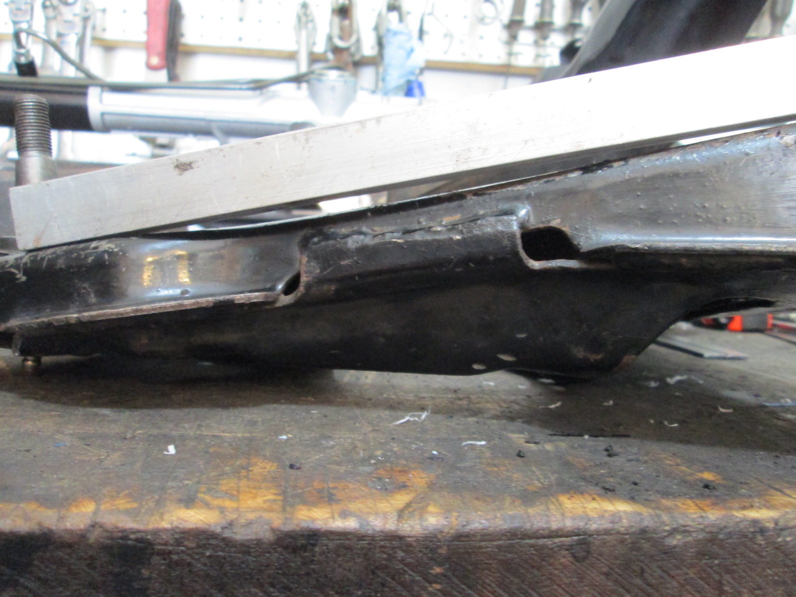
Not much real world progress today... I did tear down the crossmember so it would be easier to get measurements.
The a-arm I measured (and detailed) yesterday had a distinct bow in the center of it... close to 1/8" gap in the center, when I eventually checked it against Blooze's drawings, his didn't show any bow, so I checked another less abused a-arm and sure enough, the black one is bent. This is an a-arm that was modified for use with a RCC coilover kit. I suspect the shock didn't have enough travel and was being the suspension stop vs. the bump stop, which put very high loads in the center of the spring area, right where this one is bent down. Just another reason I was woefully unimpressed with that kit...
Bent 88 lower a-arm:
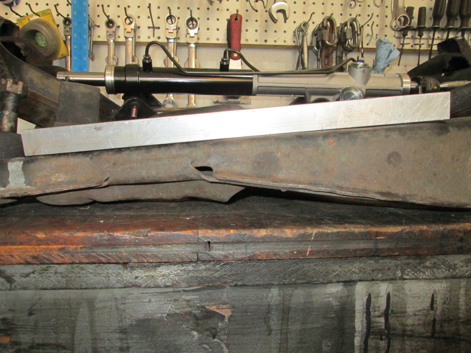
Good 88 lower a-arm:
Today was mostly detailing more of the crossmember, an un-bent lower control arm, the 88 knuckle, etc. Laptop and I spent most of the day at the work bench doing lots, and lots, and lots of measurements.
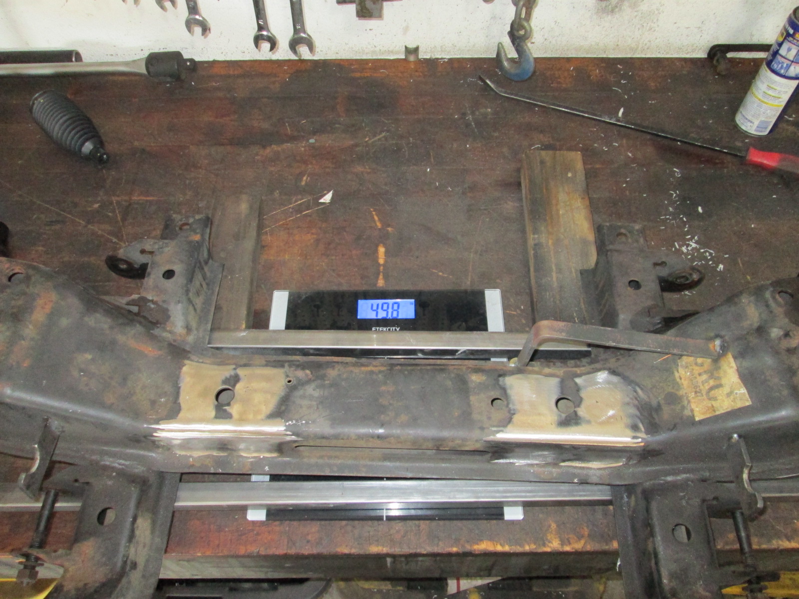
While the crossmember was bare, I did measure it on a scale that was zeroed with the 1" tubes. I think some quick work with the plasma cutter can shed a few excess lbs...
Not sure when the last time this was calibrated, but it definitely was a hot one.
[This message has been edited by fieroguru (edited 08-24-2021).]
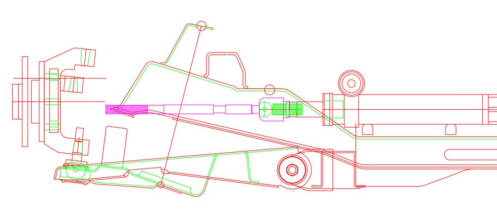
I didn't spend much time in the garage today, just long enough to cut open upper and lower ball joints and inner/outer tie rods to get precise pivot details. Also detailed out the outer tie rod and upper ball joint. Some work creating blocks of the geometry and started playing around with the stock setup.
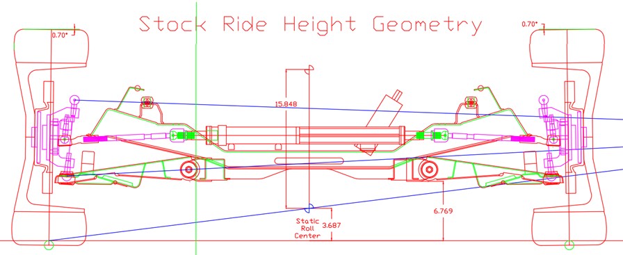
The stock 88 front suspension is pretty good overall - especially at stock ride height. If I can get my custom knuckle/Gen 4 rack setup to be close to the stock 88, I would be very happy.
Stock Geometry with 0.7 degrees of static negative camber:
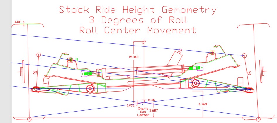
With 3 Degrees of Roll:
With 1.5" of bump:
[This message has been edited by fieroguru (edited 08-28-2021).]
Here is where I am at with the custom knuckle, adjusted tie rod placement, 8 degrees caster, 1 1/2" lowered stance, and a 1/2" spacer under the inboard upper a-arm pivot.
Is your custom knuckle going to be taller than the stock one? Extending the lower ball joint boss to lower the car? Raising the UCA inner pivot is not normally complimentary to good geometry.
How much lateral migration do you have with the roll center at 3 degrees body roll?
[This message has been edited by Will (edited 08-26-2021).]
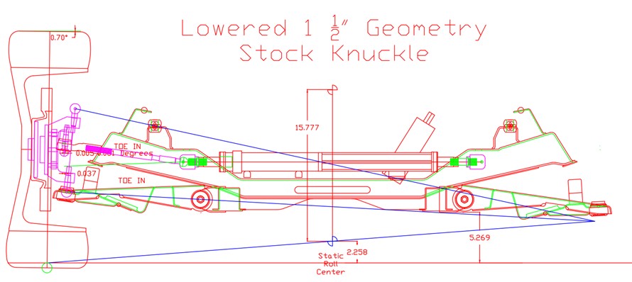
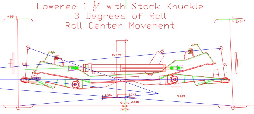
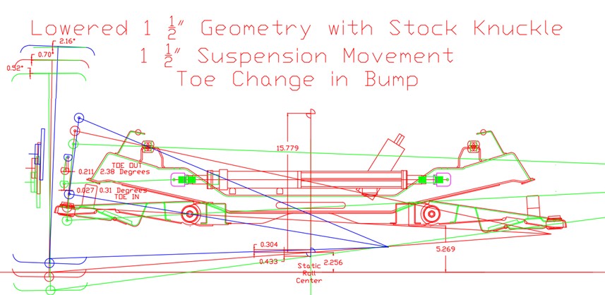
Here is a stock suspension lowered 1.5 inches with lowering springs:
CG is lowered 1.5" and distance between the CG changes to 15.78" from 15.85" so no significant change in roll resistance, because the roll center dropped about as much as the CG changed.
Notice improved camber gain, but at the expense of the roll center moving 2.35" laterally.
Definitely more bump induced toe change.
Most 88 Fieros running autocross or track days with a stock based suspension that have been lowered, are running a geometry setup like above, or worse (geometry gets worse as you lower it further). It works, but definitely not ideal.
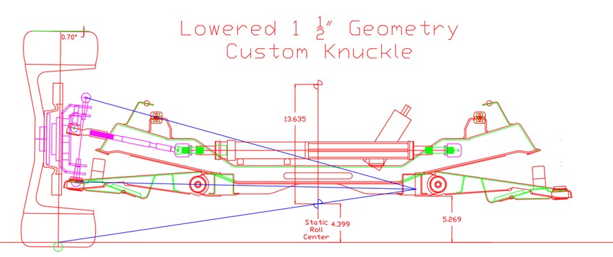
Here is the current geometry for the modified knuckle. The CG was lowered 1.5" and the RC was raised, so the distance between the two becomes 13.64 vs. 15.85 or a 14% increase in the resistance to roll.
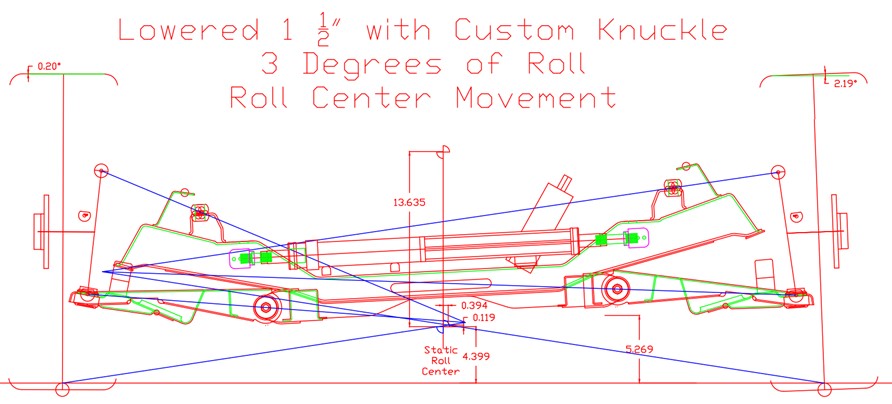
With 3 degrees of roll, the loaded wheel still has a smidge of negative camber, the unloaded wheel has just over 2 degrees positive camber and the roll center only shifted 0.394" vs. 2.35" with lowering springs.
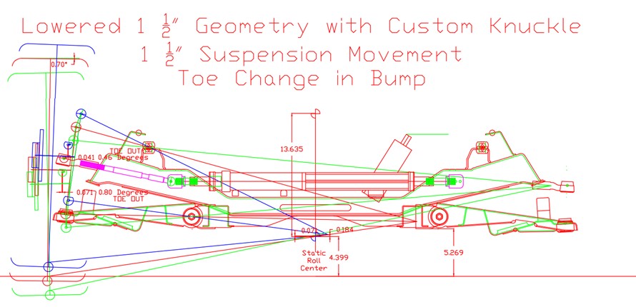
Toe change with bump is slightly better than stock with compression, worse than stock with rebound. I still have some options to refine outboard tie rod height, lateral position of inner tie rod pivot, as well as changing the elevation of the rack position.
quote
Originally posted by Will: Is your custom knuckle going to be taller than the stock one? Extending the lower ball joint boss to lower the car? Raising the UCA inner pivot is not normally complimentary to good geometry.
How much lateral migration do you have with the roll center at 3 degrees body roll?
The knuckle is about 1" taller split between the upper and lower ball joint positions. The lower ball joint was to assist with the drop and get the lower a-arm back to within 1" of stock. The top was largely done for ball joint stud/nut clearance to the C5 CV (AWD in the future).
With the new/reworked layout, the spacer isn't used anymore.
From the updated graphs above, it looks like the custom knuckle has a little more lateral migration of the roll center than stock, but still about 75% less than what you get with a stock suspension lowered 1 1/2" with lowering springs.
[This message has been edited by fieroguru (edited 08-28-2021).]
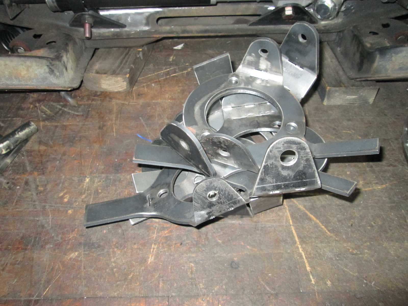
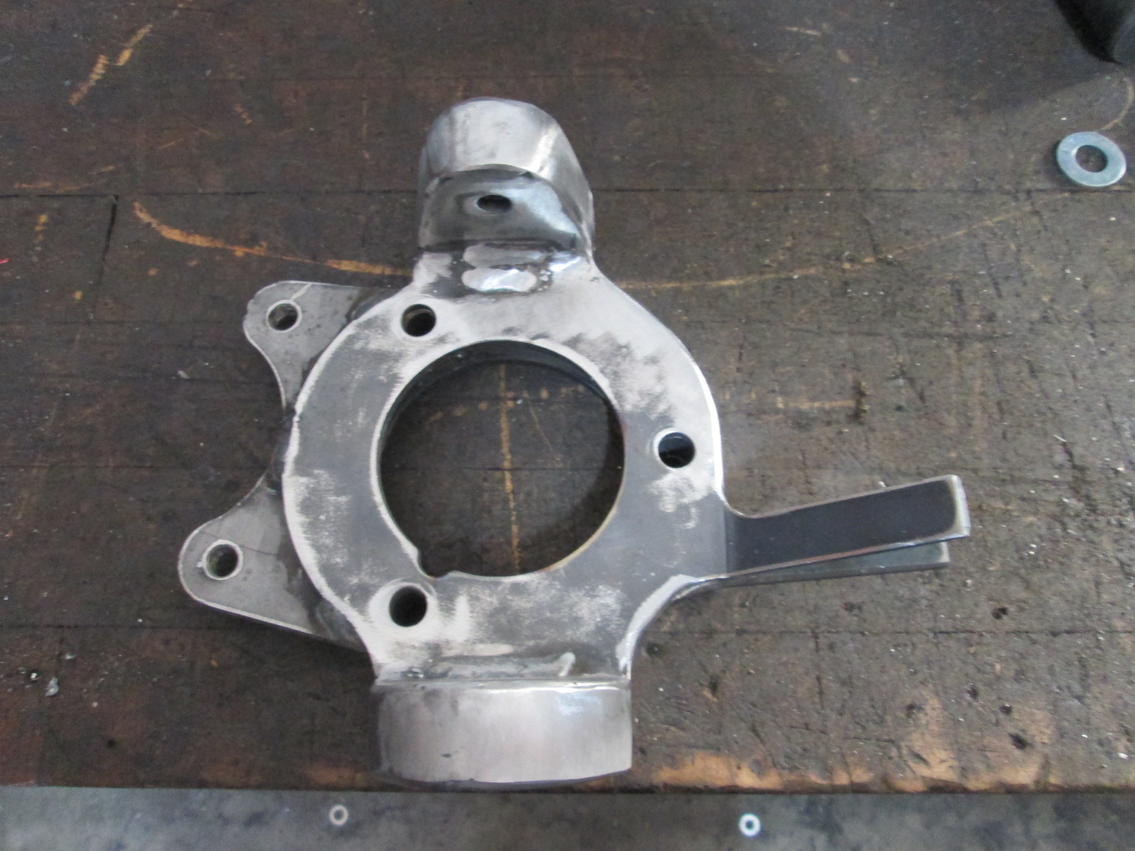
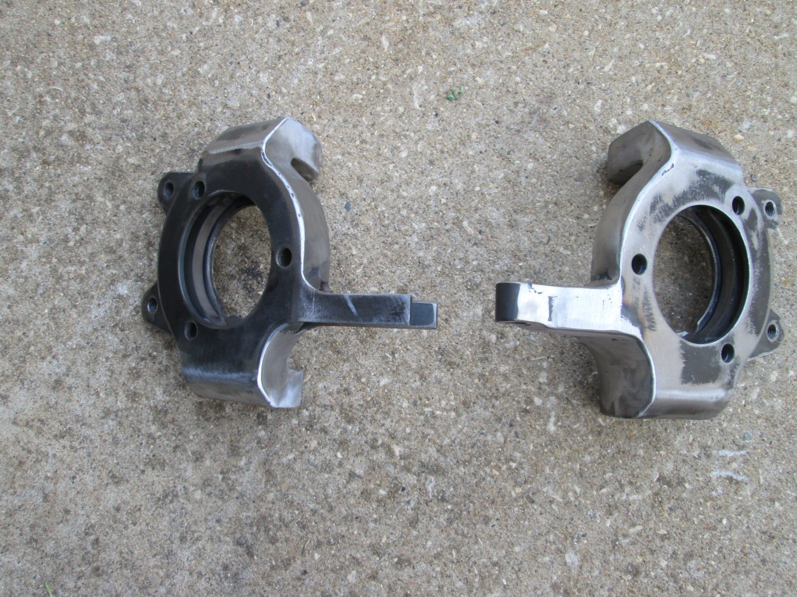
After some more tweaking the tie rod placement, I took the geometry from the drawing and transferred it to a file for the plasma cutter and made the next set of test knuckles... getting pretty close. I need to measure the lower ball joint sections and compare them to the the drawing to see what changes are needed to align the upper and lower ball joints at 6 degrees.
These two pictures make it look like I know what I am doing!
These are the ones for fine tuning the process:
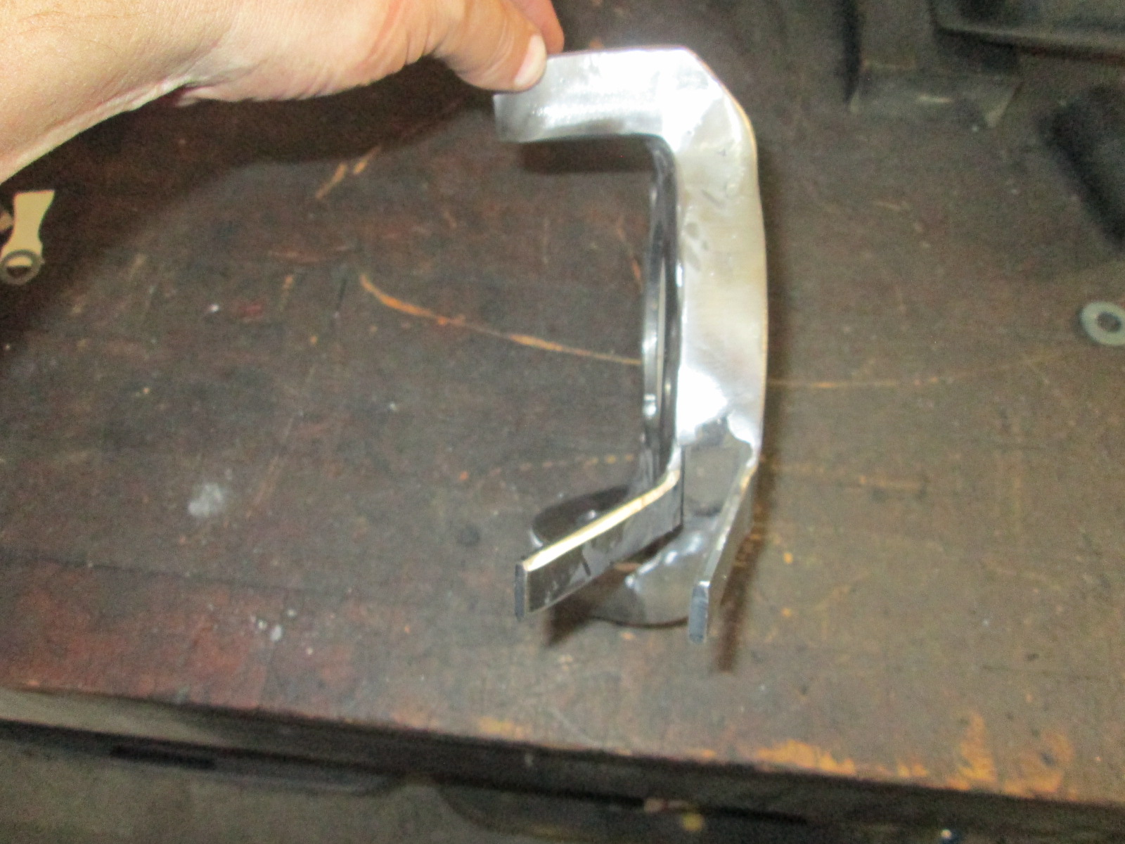
I have the Brembo caliper bracket designed and just need to burn it out. It is rotated up 8 degrees so the caliper will be perfectly vertical with the knuckle set for 8 degrees caster... assuming it will clear the upper a-arm.
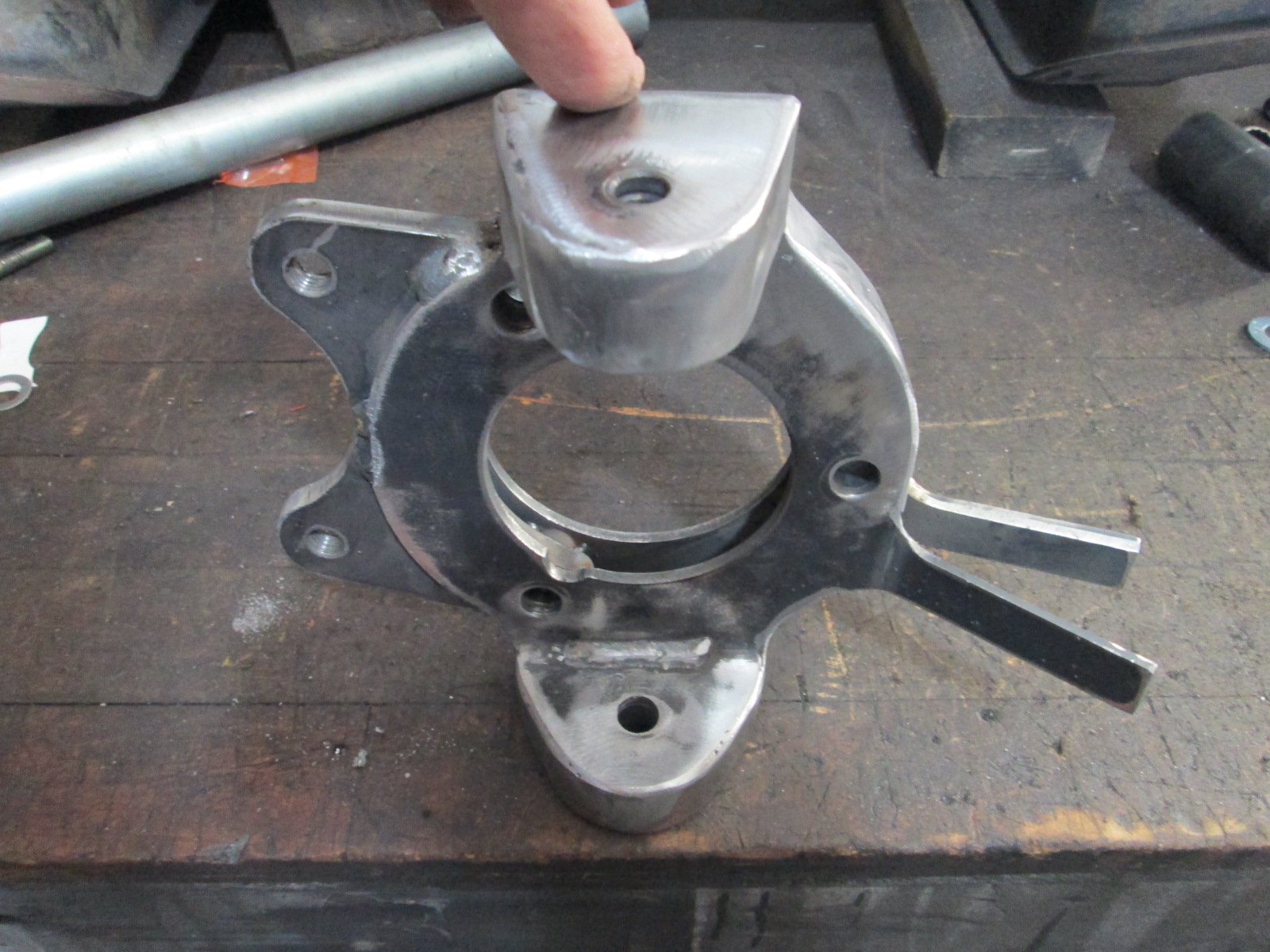
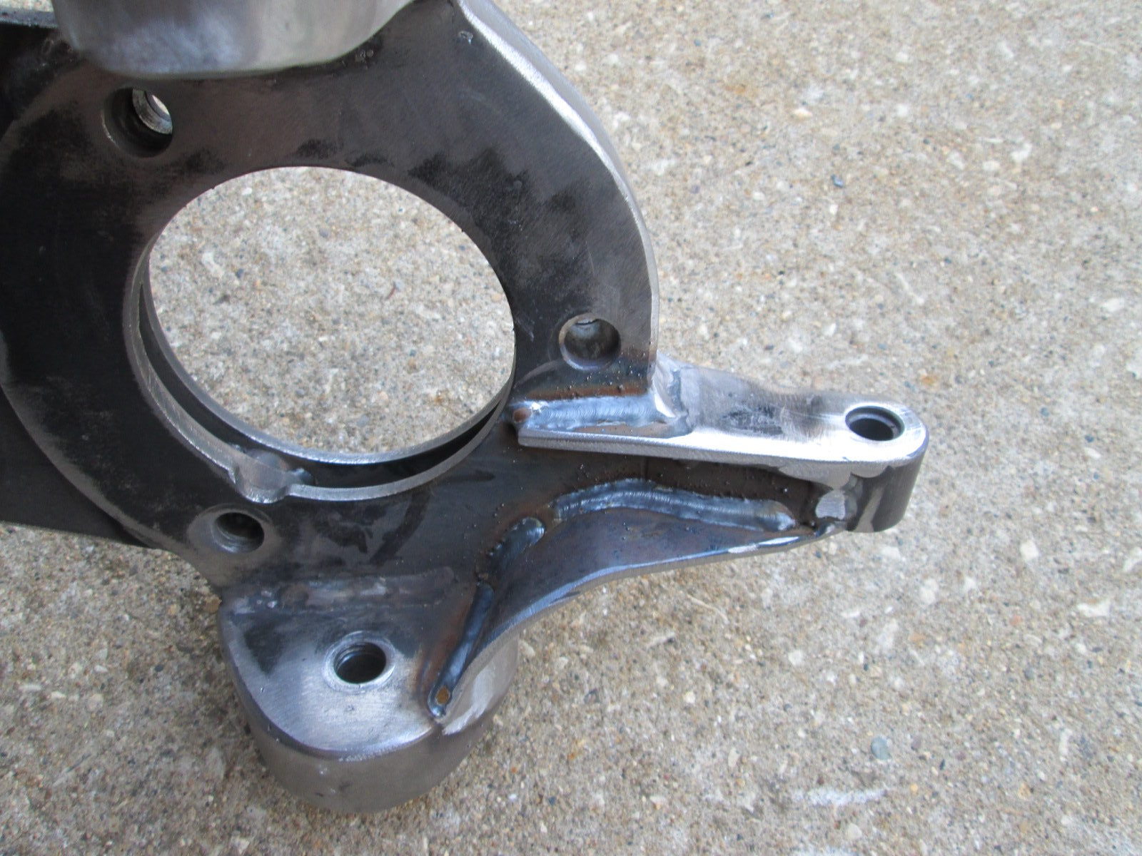
Getting a little closer at looking like a proper knuckle with the brake bracket added.
The brake bracket is held in place by 2 of the 3 wheel bearing bolts. I just need to machine the proper spacers front/rear to perfectly center the caliper. It doesn't look like it in the pictures, but I only need to take about 0.030" from the inboard spacer and add it to the outboard one.
Edit... I was able to move some of my AutoCAD geometry around and put the Brembo caliper on an 88 knuckle with the 12.8" rotor. There are a few challenges, but nothing is a show stopper yet. The Brembo will need the pressed in threaded sleeves removed to allow the adapter plate to be of sufficient thickness. Length of the bolts will need to be limited unless there is room to rotate the caliper upwards some.
Well, if you find that after you finish your project, and you want to make some more money with side projects, i'd love to get rid of all my Arautt Motor Sports brake stuff and install the 12.8"/Brembo stuff on my stock 88 knuckles. (both front and back). Even if you just make brake brackets and we have to source the Brembo's and rotors, i'd still take two sets. I just don't trust the Arautt MS stuff on my 88. I really don't like the rear b/c of the 3/8 spacer you need to install on the axle/hub. IMO that's a lot of spline i'd like to have back.
Knuckle about 80% welded... starting to look like something.
Right now it is about 6 oz heavier than the stock 88 front knuckle, which is 5 lbs 2 oz. The finished knuckle will be 1-2 lbs heavier than stock, which I am OK with.
[This message has been edited by fieroguru (edited 09-06-2021).]
Lots of cutting welding and grinding but the other side is about 80% build and the original side now has the tie rod arm complete. I still need to ream the holes and fit the ball joints to the proper depth, but maybe one more weekend and the front knuckles will be done. Then I get to move onto crossmember and a-arm mods.
These knuckles are one of only a few sets of fabricated knuckles I've seen, and so far, the only ones I've seen that I would be comfortable with being on a car. IIRC, you were going to use C5 wheel bearings, FWIW, your design should support several other drop in and go wheel bearings, including "Dustbuster" minivan bearings, and Jeep bearings, which are both 5X114.3(4.5") and opens up the wheel options significantly.
If I were to guess, you're a step or two ahead of me on that though, especially if you're considering any kind of production run.
------------------ "I am not what you so glibly call to be a civilized man. I have broken with society for reasons which I alone am able to appreciate. I am therefore not subject to it's stupid laws, and I ask you to never allude to them in my presence again."
These knuckles are one of only a few sets of fabricated knuckles I've seen, and so far, the only ones I've seen that I would be comfortable with being on a car. IIRC, you were going to use C5 wheel bearings, FWIW, your design should support several other drop in and go wheel bearings, including "Dustbuster" minivan bearings, and Jeep bearings, which are both 5X114.3(4.5") and opens up the wheel options significantly.
These are great work. Since they are stressed skins, I'd gusset the lower ball joint up to the bearing bolt circle. Without that gusset, the failure mode for the 90 degree bend would be to buckle.
The Jeep bearings have a larger housing and mounting bolt circle than the GM bearings, so they'd need specific knuckles.
Thanks guys! These knuckles have been quite the project, but I am pretty happy with how they are coming out. I do agree about adding another gusset to the lower ball joint area and that was the original plan with the blue tape mockup a page ago. There are some very slight differences between the C5 and W-body wheel bearings, but they both fit the knuckle, which is an added benefit.
I am planning to finish them up this weekend and start working on the lower a-arms. Most of the parts to finish up the rack mounting and inner tie rods are in, so I might be able to finish that up as well.
I finished all the welding on the first knuckle, but didn't take any pictures...
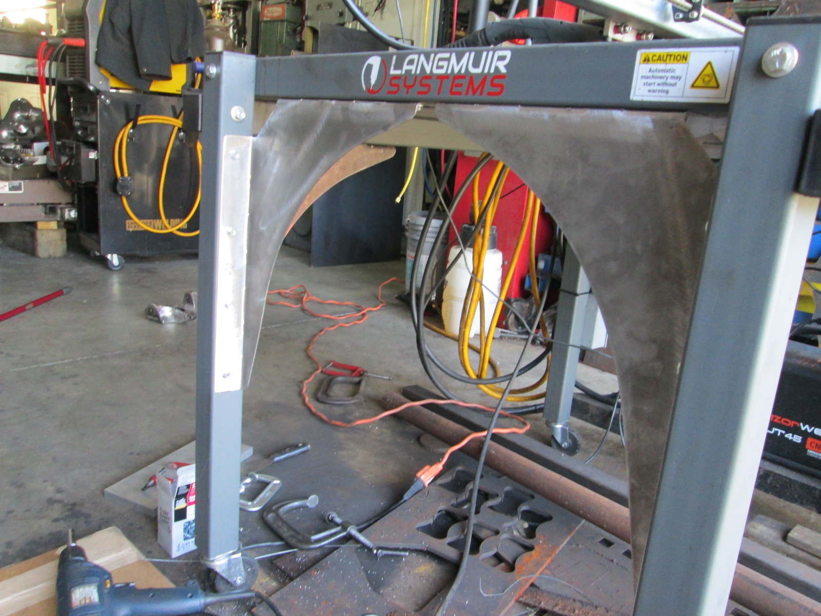
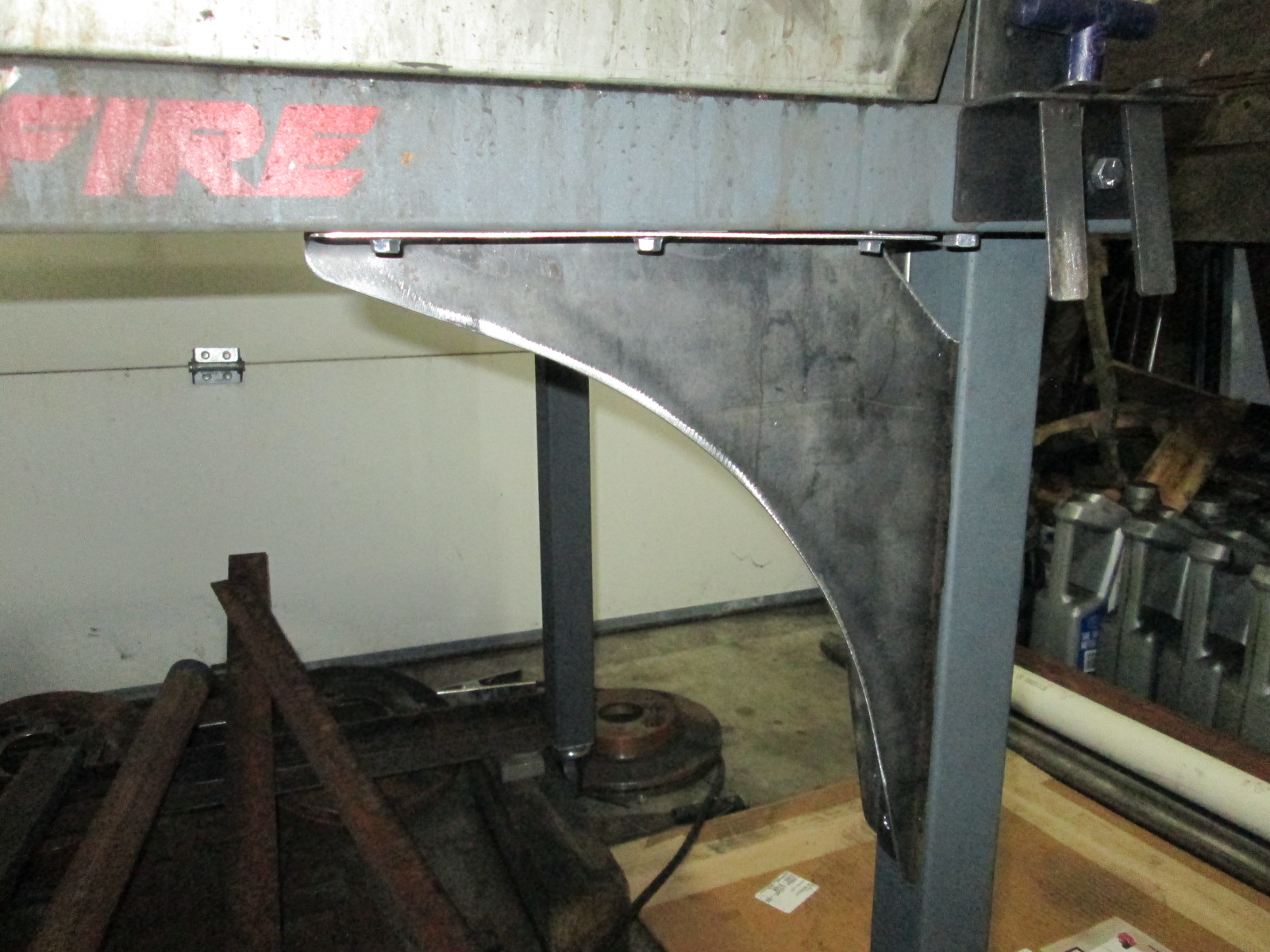
Then I started to play around with making some leg braces for my plasma cutter. Its big brother from Langmuir comes with something similar, and I was never a big fan of the bolted bar method for the legs.
The inspiration:
My version:
I did have to finally breakdown and buy the official license for sheetcam. I forget how many lines of G-code the free version is limited to, but this little side project took more than that... It is 22" long, I need to refresh my memory of the limits of the table and made one over 30" so I can mount it over my work bench. I did have to make a few tweaks to the logo to keep it all together, but overall I think it looks pretty good.
Are you going to destroy a knuckle (hydraulic press setup?) to see what it takes to break it, or are you confident enough to run it based on analysis only?