Been slowing making progress on the LS4 engine work.
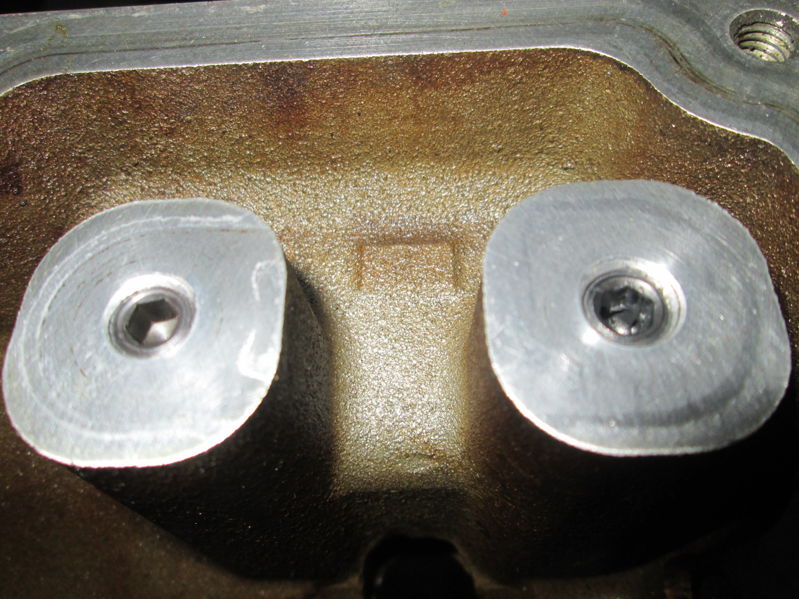
Since I am deleting DoD/AFM and had the engine torn down, I went ahead and tapped the DoD oil feed ports and capped them. While the non-DoD valley cover had o-ring seals for these I will feel better knowing they are capped.
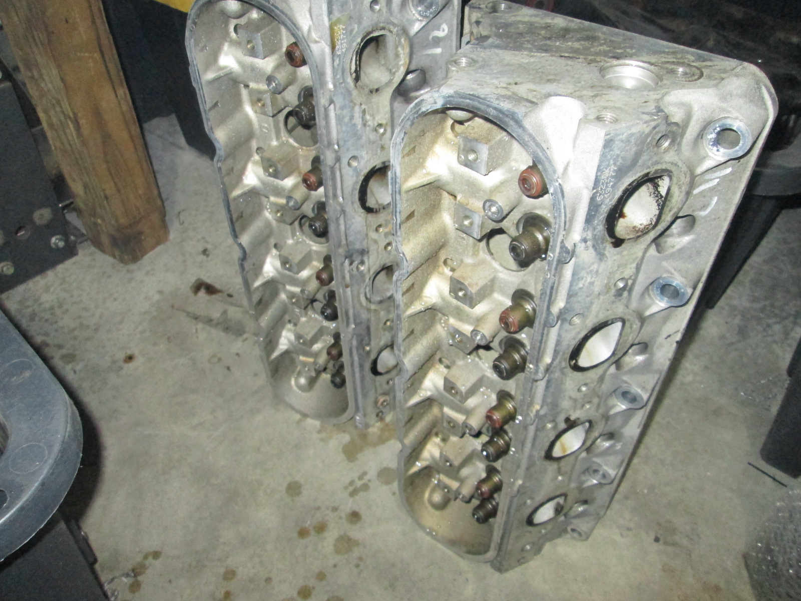
I also tore down the heads and started cleaning them. They still have a couple more rounds of cleaning.
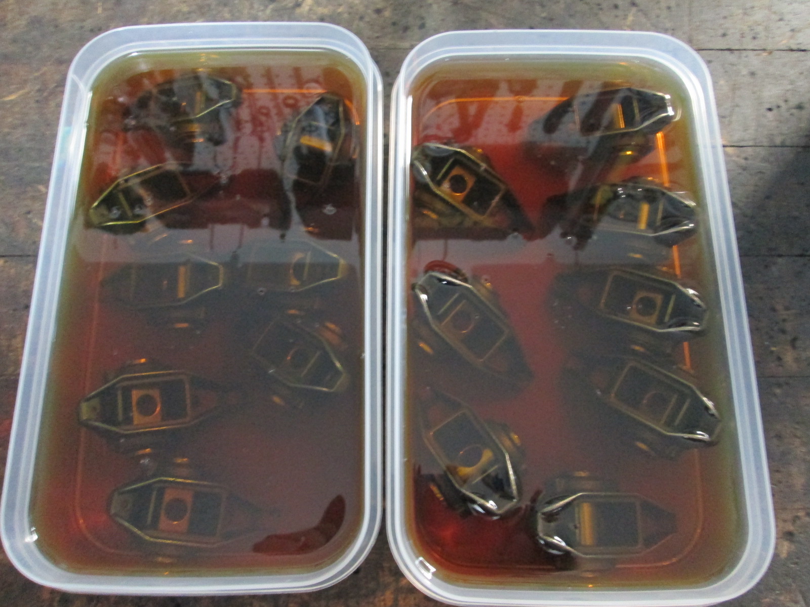
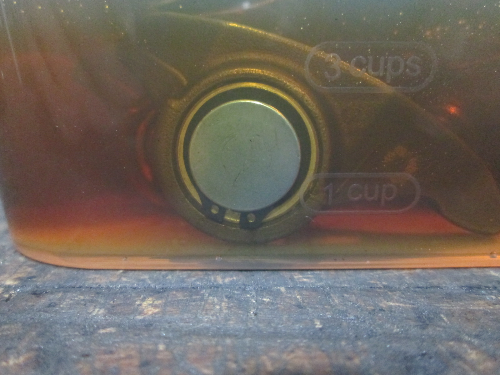
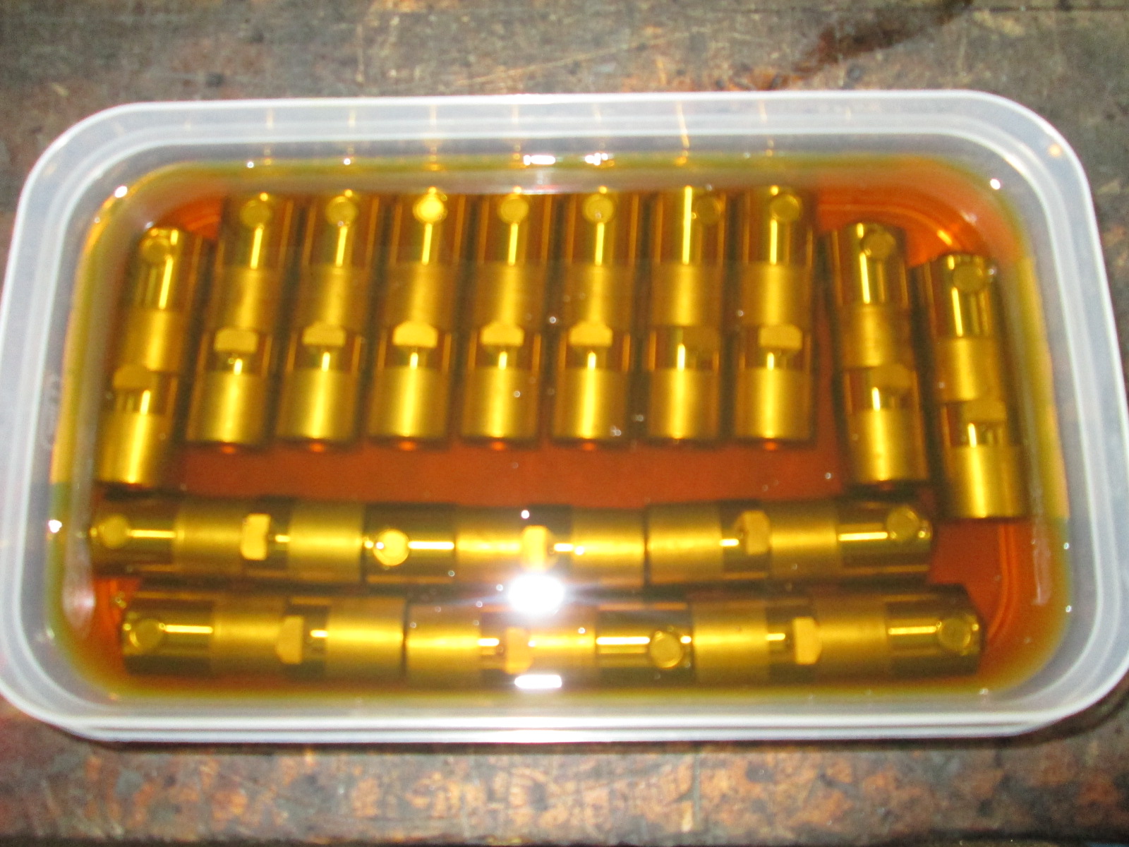
Installed the Smith Bros (no relation) bronze bushing upgrade for all the rockers. Then put them in an oil bath until they will be installed:
Also, pulled the new LS7 lifters out of the new parts stack and put them in an oil bath until they are needed as well.
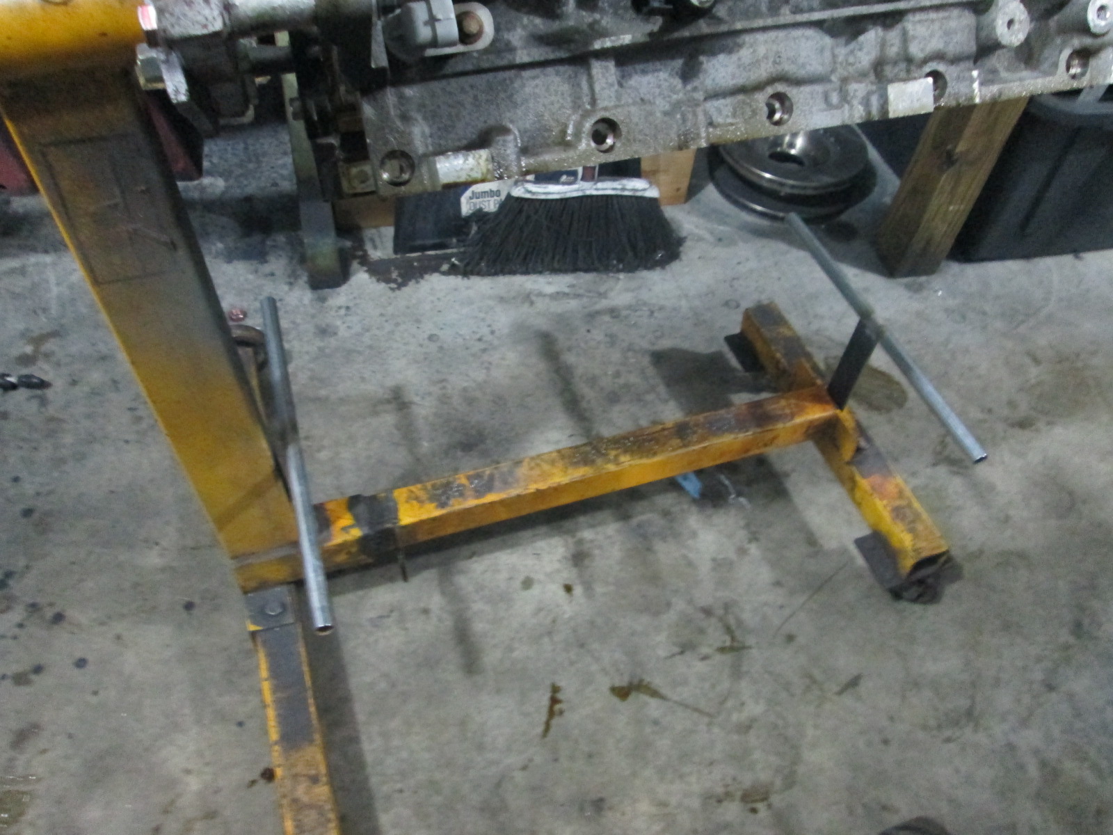
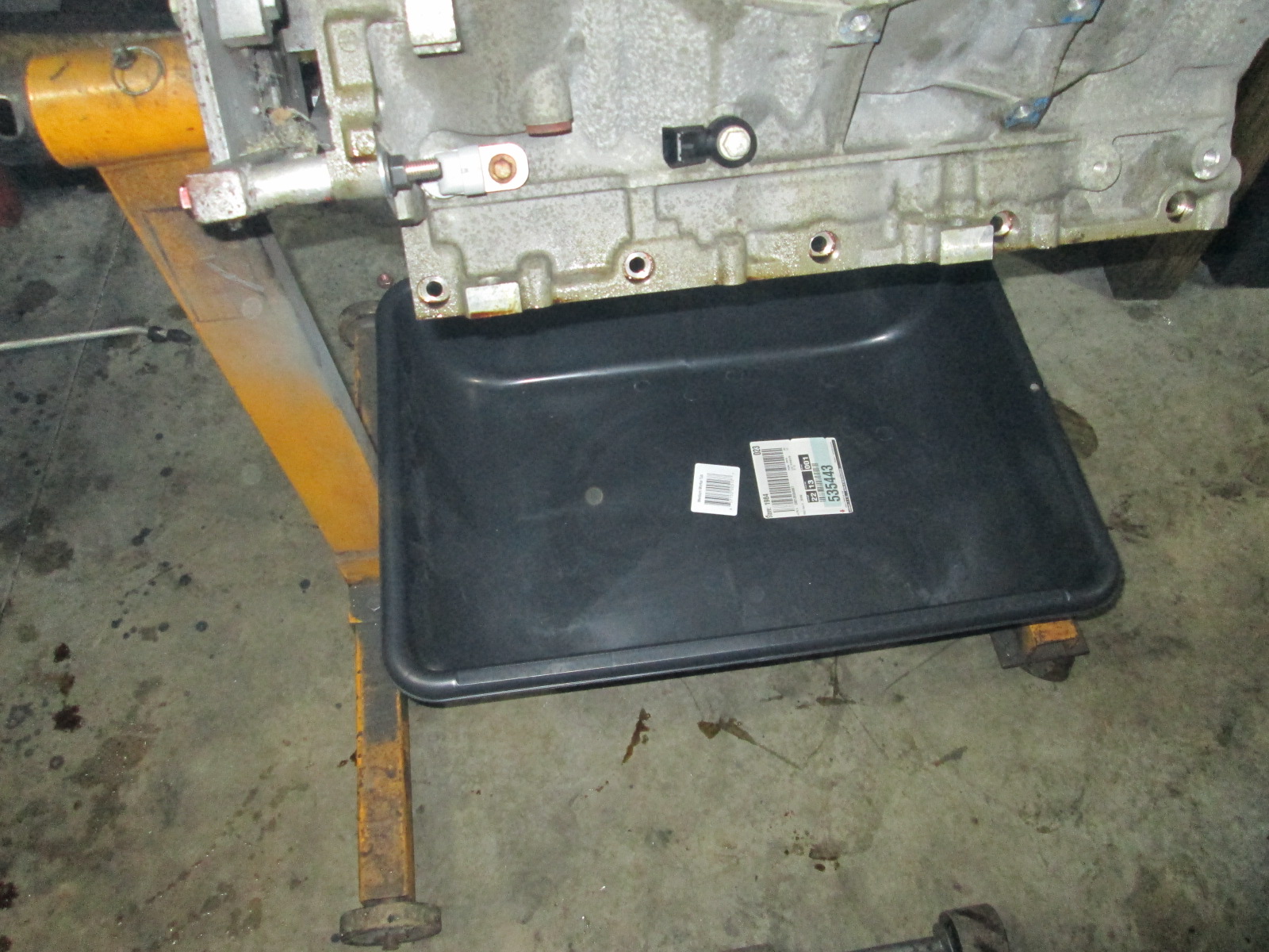
I am not sure what took me so long... but I finally make a couple of braces to mount a drip pan to the engine stand.
The next several things I need to do are: Finish cleaning pistons, heads, and block Verify top ring gaps... need 0.022" minimum Lap valves, install new valve seals, install BTR dual springs Install new bearings
I have been pondering multiple paths forward from an ECM perspective. I am seriously considering swapping in a 24X reluctor on my crank so I can run the E40 ecm. Sad to say that in the 6 years since I did this swap, development on adding basic features to the E67 ecm (like direct wired AC request, cruise, and VSS input for manual transmission) haven't happened. Even the add on modules are still hit and miss.
If I stay with the E67 ecm (58X), I have 3 primary paths: Keep the LS4 calibration (auto only), continue to use the TCM for the VSS signal, continue to use the AR module for cruise, and continue to run AC w/o the AC request... just like I have been doing that last 6+ years. This is by far the cheapest and easiest. Switch to the TBSS calication (LS2/auto), use the TCM for VSS signal, direct wire the cruise, and run AC w/o the request signal. Switch to the CTSV calibration (LS2/manual), eliminate the TCM and direct wire the VSS, use my AR cruise module, and run AC w/o the request signal.
Switching to the E38 ecm (also 58X) gets me to the same spot as the CTS-V option above.
If I go with the E40 ecm (24x), I could: Switch to the SSR calibration (LS2/manual), eliminate the TCM, direct wire the VSS, direct wire cruise, and run AC with the request signal. It will still allow my flex fuel conversion and it still uses a traditional VE table vs. the coefficient equations in the E67/E38, which makes tuning easier and more precise. Overall this would be a cleaner factory install, allow removing some add-on modules, simplify the wiring, and save some weight. Cost to do the conversion is about $70 for a new 24X reluctor and 1X timing gear. I will have to fabricate a fixture to install the reluctor in the proper position (a tool is available, but is over $200). I will also have to get an E40 ecm loaded with the SSR calibration. Overall it will be more expensive and more work, but I think it is the best path forward...
[This message has been edited by fieroguru (edited 01-01-2020).]
Originally posted by fieroguru: I have been pondering multiple paths forward from an ECM perspective. I am seriously considering swapping in a 24X reluctor on my crank so I can run the E40 ecm. Sad to say that in the 6 years since I did this swap, development on adding basic features to the E67 ecm (like direct wired AC request, cruise, and VSS input for manual transmission) haven't happened. Even the add on modules are still hit and miss.
If I stay with the E67 ecm (58X), I have 3 primary paths: Keep the LS4 calibration (auto only), continue to use the TCM for the VSS signal, continue to use the AR module for cruise, and continue to run AC w/o the AC request... just like I have been doing that last 6+ years. This is by far the cheapest and easiest. Switch to the TBSS calication (LS2/auto), use the TCM for VSS signal, direct wire the cruise, and run AC w/o the request signal. Switch to the CTSV calibration (LS2/manual), eliminate the TCM and direct wire the VSS, use my AR cruise module, and run AC w/o the request signal.
Switching to the E38 ecm (also 58X) gets me to the same spot as the CTS-V option above.
If I go with the E40 ecm (24x), I could: Switch to the SSR calibration (LS2/manual), eliminate the TCM, direct wire the VSS, direct wire cruise, and run AC with the request signal. It will still allow my flex fuel conversion and it still uses a traditional VE table vs. the coefficient equations in the E67/E38, which makes tuning easier and more precise. Overall this would be a cleaner factory install, allow removing some add-on modules, simplify the wiring, and save some weight. Cost to do the conversion is about $70 for a new 24X reluctor and 1X timing gear. I will have to fabricate a fixture to install the reluctor in the proper position (a tool is available, but is over $200). I will also have to get an E40 ecm loaded with the SSR calibration. Overall it will be more expensive and more work, but I think it is the best path forward...
I am actually in a similar situation. Since my '93 Northstar block requires honing, which then requires new pistons and rings, I have been looking at upgrading to a 2006+ block. This gives me the chance either to keep my current 0411 OR upgrade to a 58x controller. I don't have the 24x option. My big concern is drive by wire. I'm don't think that's accessible to me with the 0411, even though in theory it has the hardware to operate a DBW throttle. I currently have direct wired VSS, direct wired A/C and can switch to transducer-based compressor control in order to skip the Fiero safety switches using the Cadillac compressor. If I switch up to a 58x computer, I can get DBW, but it sounds like the best I can do for the other functions is direct wired cruise via the TBSS OS. Didn't the Pontiac G6 have a VSS in the F40? Is that not direct-wired to the ECM? Is that OS not adaptable to an 8 cylinder engine?
[This message has been edited by Will (edited 01-04-2020).]
I am actually in a similar situation. Since my '93 Northstar block requires honing, which then requires new pistons and rings, I have been looking at upgrading to a 2006+ block. This gives me the chance either to keep my current 0411 OR upgrade to a 58x controller. I don't have the 24x option. My big concern is drive by wire. I'm don't think that's accessible to me with the 0411, even though in theory it has the hardware to operate a DBW throttle. I currently have direct wired VSS, direct wired A/C and can switch to transducer-based compressor control in order to skip the Fiero safety switches using the Cadillac compressor. If I switch up to a 58x computer, I can get DBW, but it sounds like the best I can do for the other functions is direct wired cruise via the TBSS OS. Didn't the Pontiac G6 have a VSS in the F40? Is that not direct-wired to the ECM? Is that OS not adaptable to an 8 cylinder engine?
I have tried those ready build pans, but for some reason they fit like crap on my engine stand and eventually got tossed. If I remember right, it has to do with this stand being a 4 wheel setup and the angle that attaches the front wheel crossmember to the main stand won't allow them to rest properly on the main lower tube. I probably could have done some cutting/welding to the the stand to make a $45 pan work, or do about the same to make a $7 pan fit. Given that every time I turn around, I am buying more parts and LS specific tools for this upgrade... I went the cheap route.
Unfortunately with the E67 (and E38) you basically have to choose what you want direct wired and what you want as a work-around.
The TBSS calibration will get you direct wired ecm controlled cruise control, but it doesn't have a direct wired VSS, and isn't a factory manual transmission calibration. The pin locations for VSS input from the other E67 manual calibrations have been verified to not work. So on a manual transmission applications you either run w/o vss input or keep the TCM wired up for the VSS signal (which is what I did originally with the LS4 calibration).
The CTS-V has a factory manual calibration AND you can direct wire the VSS, but it doesn't accept direct wired cruise. There are some cruise modules that plug in between the DBW pedal and ECM, but they are $300+ and very hit and miss. Old school AR module pulling the pedal works, but isn't as refined as the ECM controlled cruise.
None of the E67s (or E38) allow a direct wired A/C request, but given the processing speed of the ecm you can make some changes to the airflow and RPM settings to keep it from stalling the engine at idle.
I was hoping someone would come up with a can bus module that accepted the AC request, cruise signals, and VSS input for the E67 swaps... but so far that does not exist.
Interdasting. So without the A/C request line, the A/C has to be wired to be completely independent of the ECM? IE, if the ECM never understands it's receiving an A/C request, it never activates the compressor control output, right? So in addition to lack of idle compensation, you also have to manually turn off the A/C when you run the engine out.
Without a VSS, there's no DFCO, which can have a significant impact on fuel economy.
I was hoping to ditch the cruise module and servo by going DBW.
I have the red/blue 0411, which means no DBW via that path.
Fudge.
If I am remembering right, Ryan was able to come up with a way to drop out the AC at WOT on Tom Slick's car (with E67). I would have to go digging way back in the PMs to find the info. I didn't bother and just turned it off before doing WOT runs.
If you stay 24x, you could switch to the P59 series of ecms with the green/blue connectors or E40. Both are twice as fast at the 0411 and both will support DBW and electronic cruise.
I don't have the 24x option now.
For all years, the Northstar crank wheel is in the middle of the engine and integral to the crankshaft.
The '93-'99 Northstars use a 32x crank wheel with 2 crank sensors on the forward side of the block, a few degrees above and below the crank centerline. The cam sensor is on the right (rear) bank exhaust cam and reads a single peg on the cam sprocket. The 4 coil ICM reads these sensors and sends multiple 0-5V logic signals to the PCM. Those signals are: 4x crank reference, 1/2x cam reference and 24x constant pulse width misfire detection reference. The PCM sends back the timing control enable (I'm blanking on GMs name for it right now) and actual timing signals. The ICM delivers static ignition timing at 10 degrees until the PCM drives the timing control enable, then the ICM fires the appropriate coil when the PCM drives the actual timing signal low. The interface is actually similar to the 4.9's distributor interface, which is why a '7730 can run a Northstar in batch fire. The '0411 I have uses the "1998 Oldsmobile Shelby" .bin from the Shelby Series 1 to run a '93-'99 Northstar.
The '00-'05 Northstars use the same sensors and locations, but with a different trigger wheel, different cam sprocket, a Siemens controller and a coil-on-plug style coil pack on each bank. The coil packs and crank triggering systems are unrelated. This is the hardest type of Northstar to swap. The cam sprocket uses a raised ridge on 50% of its circumference to make a sensor signal that is high for one crank revolution then low for the next crank revolution.
The '06+ FWD Northstars have a 58x trigger wheel and a single crank sensor in the valley. That crank sensor is NOT directly above the crank. The cam sensor is in the same place, but I don't know what that sprocket looks like. I should be able to swap it to my heads, though.
What's the PN for the GM 24x wheel? Maybe I can machine a Northstar crank to accept it, and then orient it to work with the old style LS sensor in the valley of a '06+ block. Did the LS9's use a different wheel? They use a sensor that has a longer "snout" than other LS sensors. Do you have the OD of the GM wheel handy?
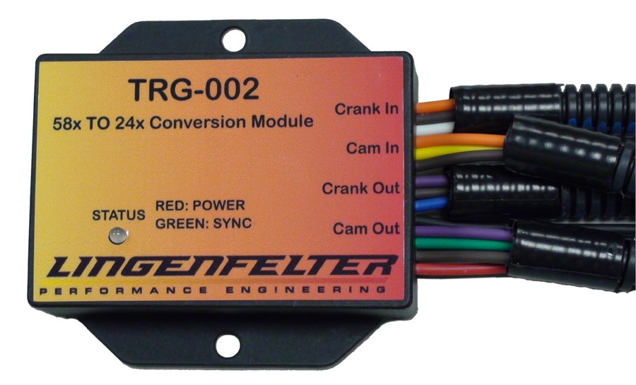
This converts a 58x crank sensor and 4x cam sensor into 24x LS crank sensor and 1/2x LS cam sensor pulse trains. I can build a 58x Northstar and then run any 24x LS controller with this.
[This message has been edited by Will (edited 01-09-2020).]
The 24X reluctor wheel is #12559353 and has an ID of 3.965 and an OD of 7.128"
The lingenfelter converter box will work, but for my swap I am trying to eliminate all the add on modules to work around issues.
Totally understandable for you, but the Lingenfelter box will work for *MY* swap!
I was looking up LS trigger wheels on the internet yesterday, and the ID is WAY too small to work on even a modified Northstar crank. I'd need something that looks more like a starter ring gear in order to modify a Northstar crank. The wiring is going to be super fun because the Northstar is right bank forward, while the LS is left bank forward... They have the same firing order, but all the cylinder pairs are reversed.
[This message has been edited by Will (edited 01-09-2020).]
I posted a link to your mount in that post (on the private sloppy page), he didn't take too kindly too it. personally, I like yours much better, but as he pointed out, it only works with some transmissions.
------------------ "I am not what you so glibly call to be a civilized man. I have broken with society for reasons which I alone am able to appreciate. I am therefore not subject to it's stupid laws, and I ask you to never allude to them in my presence again."
To be fair, there are uses for the pan beyond just transverse swaps. There are some swaps, like Datsun 240/260/280Zs that have difficulty with clearance for both headers and starter on the right side of the engine. This oil pan would make those installations easier.
The FWD bellhousing also fits better into some transmission tunnels, although there's no reason the Moroso pan couldn't be used with any other LS.
E30's have the clearance problem as well, but the crossmember location requires a front sump pan.
Having the weld beads intrude on the edges of the starter bolt holes is a pretty terrible design, but I didn't spec it. I'm surprised Moroso built that, though. I thought they knew better.
And WTF is up with that drain plug? That's a disaster poised and ready to pounce.
[This message has been edited by Will (edited 01-17-2020).]
Pistons & Rings - pulled everything apart, cleaned the pistons and rings, then checked the top ring gaps. All were just above 0.022", which should avoid them binding under boost. Then put them all back together so they can be reinstalled in the engine.
Block - did a light hone to the cylinders to remove any glazing. The bare block is light enough to carry, so took it to the car wash for some deep cleaning. Once back, I oiled up the cylinders.
Crankshaft - decided to switch to 24X, so I have been working on a locating fixture to properly index the 24X reluctor. I hope to have this fixture made tomorrow and swap the reluctor wheels.
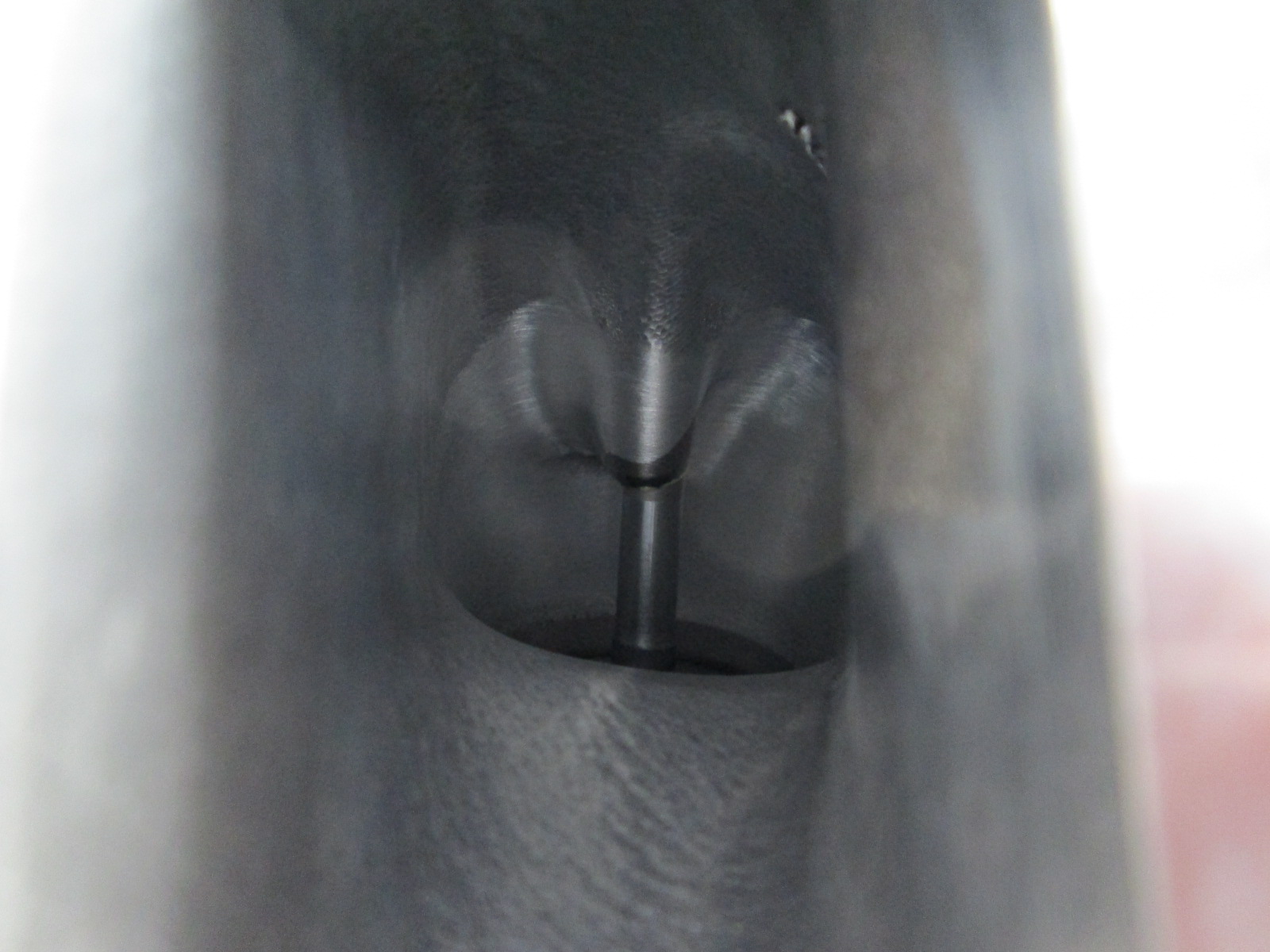
Heads - fully disassembled. The intake runners were a mess with carbon/oil build up. Lots of work and soaking to get them cleaned, but now they are clean. I am going to do some bowl work to them before I start putting them back together.
Intake - use my fine tooth file to start knocking down all the text that was case into the runners on the dorman intake. Firing order, map location, made in the usa... I don't need any of that and just want the intake runners to be smooth.
Harness - picked up another E40/T56 harness, 200 ecm pins, and lots of other harness/connector bits.
I would like to start assembling the short block tomorrow afternoon...
another great thread from the Guru. Thanks for sharing. Just out of curiosity, what do you use for engine assembly lube? I've seen everything from thick paste to thin oil recommended over time and of course, all it takes is rotating the crank twice to wipe the cylinder walls clean and very likely squeeze most lube off of rotating bearing oil clearances, etc.
Did you or do you need to degree-in the cam (unless I missed it) etc?Check piston crown-to-deck height or similar?
It's just one of the things that 'bugs' me when doing an engine reassembly, and not having a dry sump pump or accumulator that I can pre-oil with (never used either). Yes, the engines seem to survive but I almost wonder if the whole 'engine ass'y lube' marketing strategy is made up....
Originally posted by Trinten: Man... I am envious that you have the equipment, and skill, to machine, check, and assemble your own engine(s).
I still need to 'outsource' that stuff! lol
Engine building is more about cleaning, checking and keeping clean than anything. Especially when the parts are still in good shape. If I needed to have the crankshaft turned, I would have farmed that out. I love my shop equipment, but they can'g hold the precision for internal engine machine work. The hone was done with a dingle ball hole and a hand held drill, which is pretty common practice for hobbiest.
quote
Originally posted by 85-308:
another great thread from the Guru. Thanks for sharing. Just out of curiosity, what do you use for engine assembly lube? I've seen everything from thick paste to thin oil recommended over time and of course, all it takes is rotating the crank twice to wipe the cylinder walls clean and very likely squeeze most lube off of rotating bearing oil clearances, etc.
Did you or do you need to degree-in the cam (unless I missed it) etc?Check piston crown-to-deck height or similar?
It's just one of the things that 'bugs' me when doing an engine reassembly, and not having a dry sump pump or accumulator that I can pre-oil with (never used either). Yes, the engines seem to survive but I almost wonder if the whole 'engine ass'y lube' marketing strategy is made up....
Thoughts? Again, thx for sharing!
All internal engine components that have moving parts (Pistons/rings/wrist pins, rockers, lifters, timing chain, etc) are soaked in 5W30 engine oil to make sure they are fully saturated with oil and won't have any dry surfaces. Cam and crank bearings I use 90 wt synthetic on them. Once I get close to starting the engine, I will prime it with 5w30 dino oil... I still need to build the pressure bleeder for that!
I will be degreeing in the camshaft just to verify it was made properly. The camshaft I removed was off ALOT when I degreed it in. Ended up moving the dowel pin location on the timing gear to get it where is needed to be.
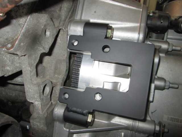
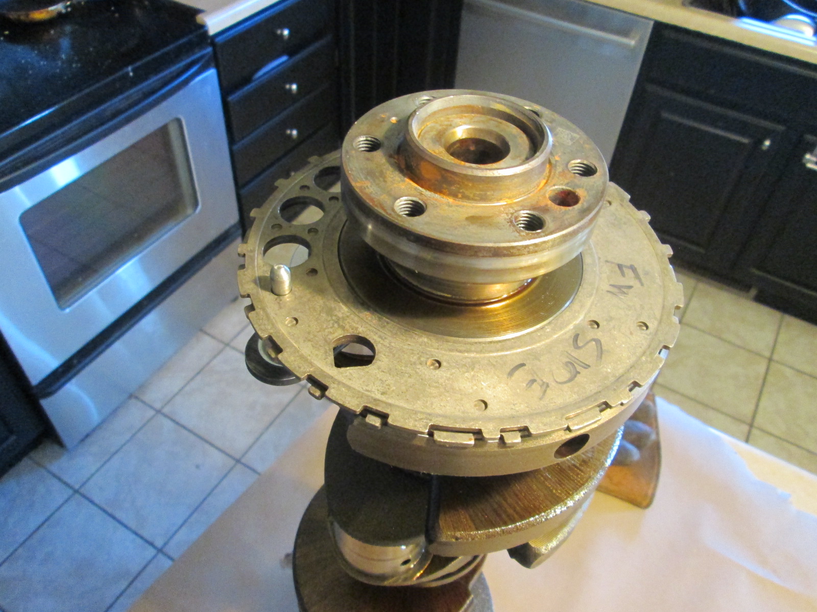
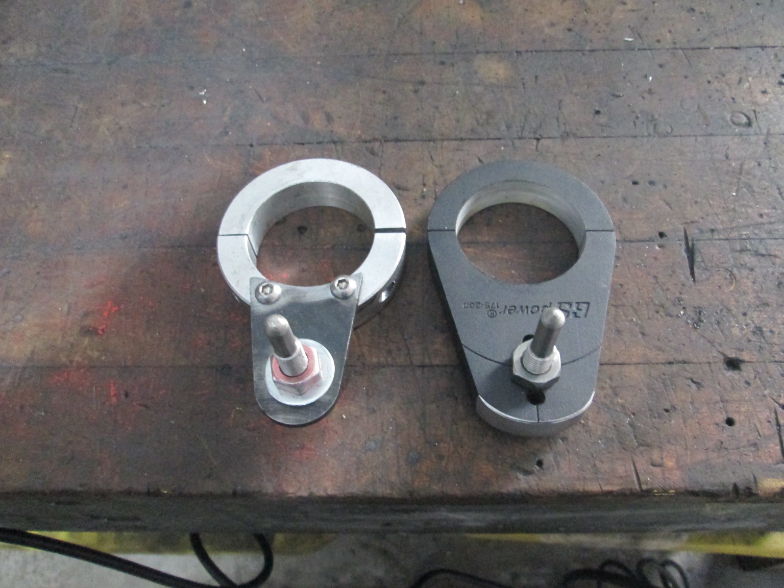
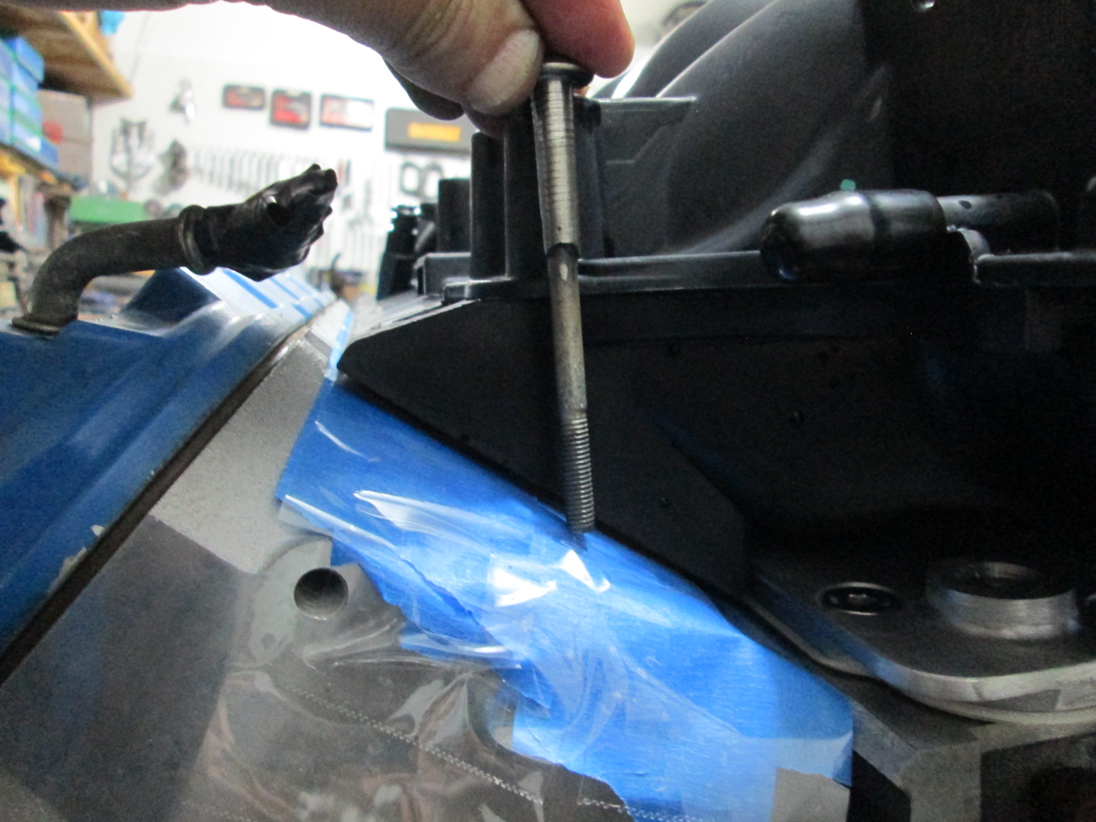
The reluctor wheels are press fitted to the end of the crankshaft, so a little heating and tapping will remove the old one. Installing the new one means heating it up in the oven and setting it in place. The challenging part is that its orientation to the crankshaft is critical. The tool below is the only known tool to facilitate the reinstallation. Besides it being over $200, I really don't like how it does everything from the end of the crank and uses the dowel pin location for alignment. Think about how I would need this to work... pull the reluctor out of the oven, set it into place, before it cools enough to keep it from spinning, I have to position this tool to the dowel location in the crank as well as the hole in the reluctor...
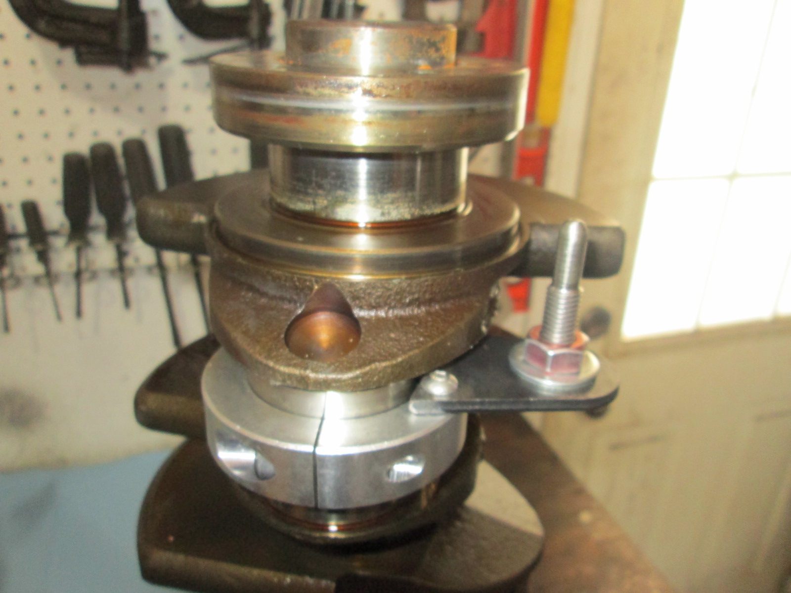
So I made my own tool using an aluminum shaft collar, bracket tab, and a bolt. I turned the ID of the shaft collar to just over 2.10", drilled & tapped a couple of holes. Shaped and drilled a roll cage tab bracket, and turned down a bolt so it has minimal clearace to the hole in the reluctor wheel... I have about $35 and an hour of my time into this tool. The placement of the dowel pin was determined using the 58X wheel that was still on my crankshaft from an 85K mile engine.
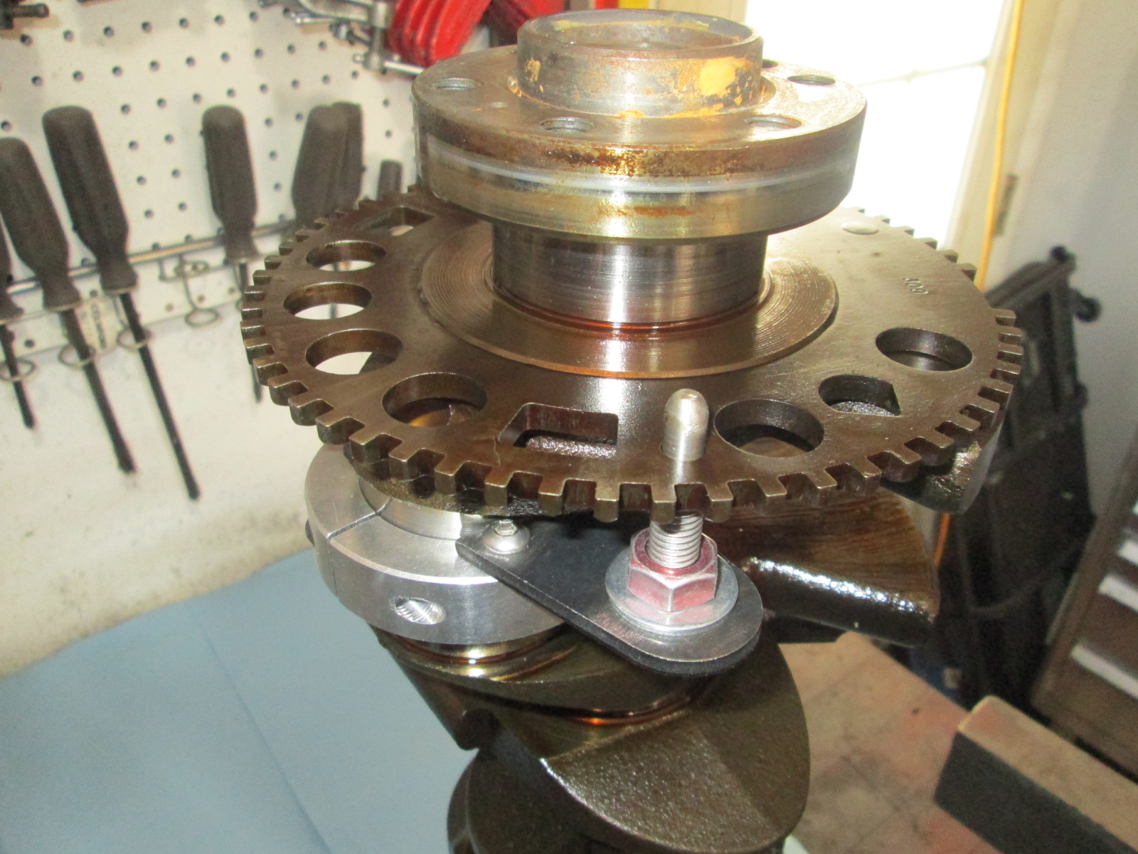
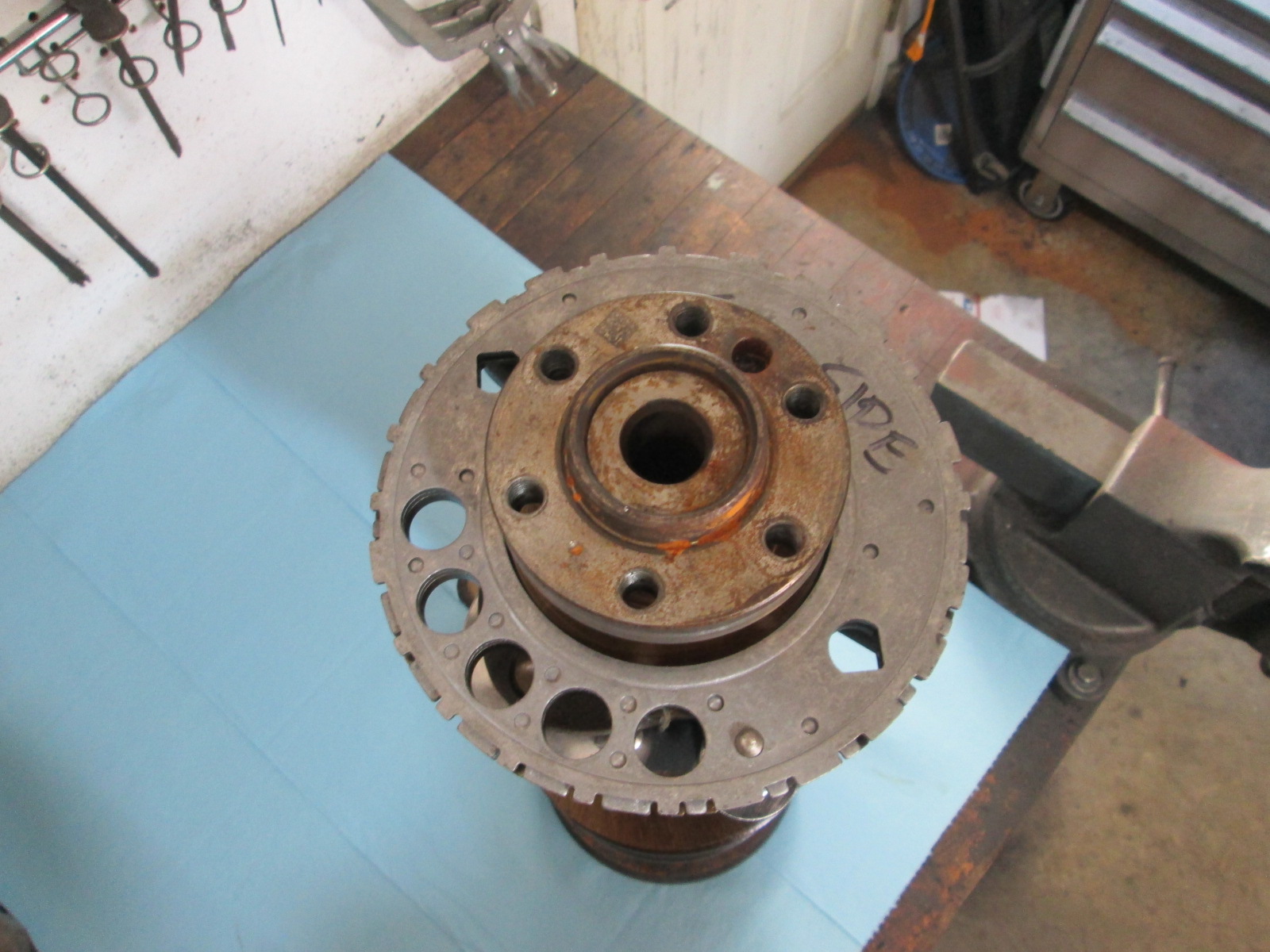
Install the tool to lock down the dowel location using the existing 58x reluctor:
Set new 24X one in place to make sure the dowels and arrows line up, then mark the flywheel side of the wheel (so you don't put it on backwards!):
Heat the old reluctor with some map gas and gently tap it off the end:
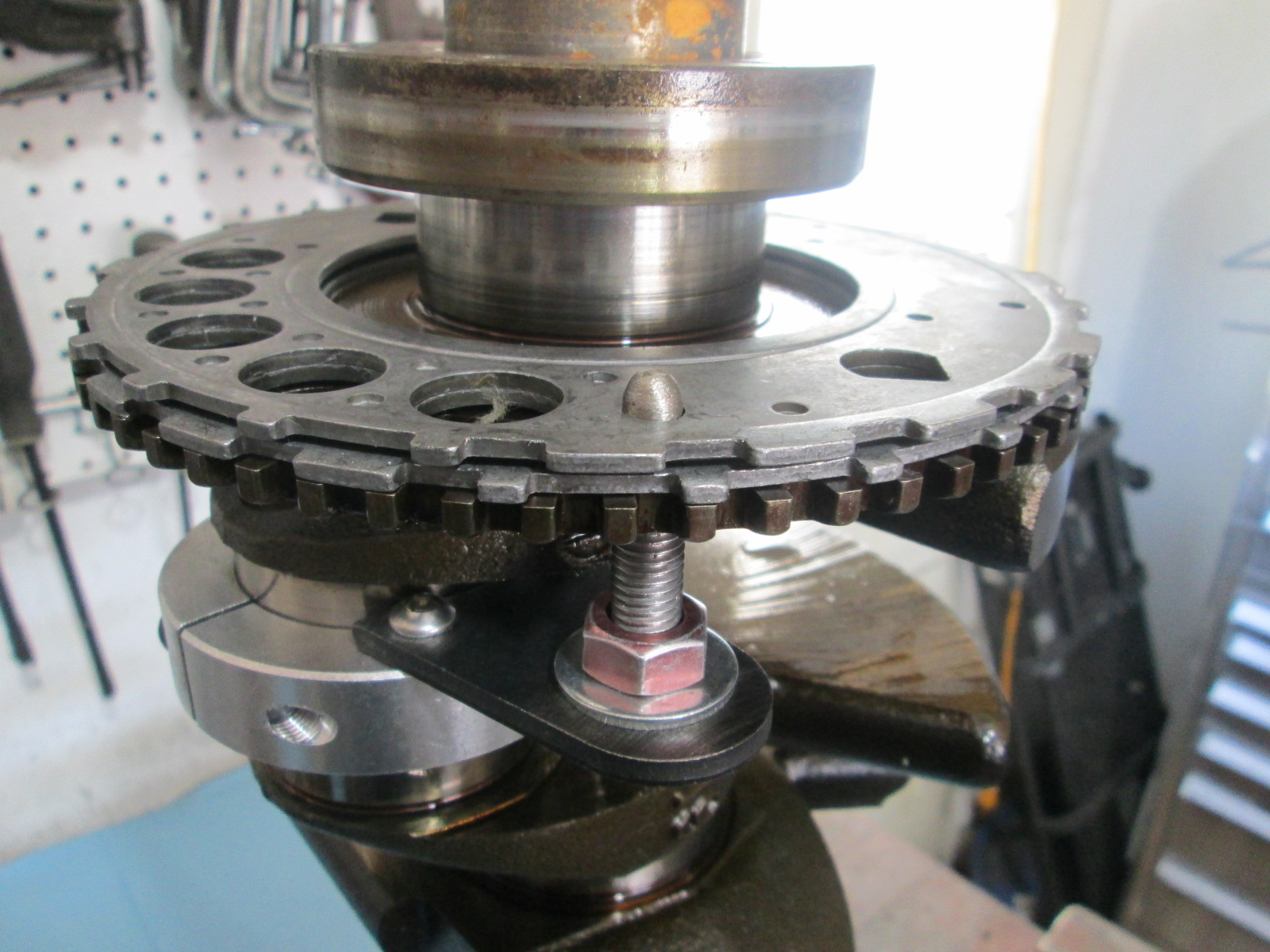
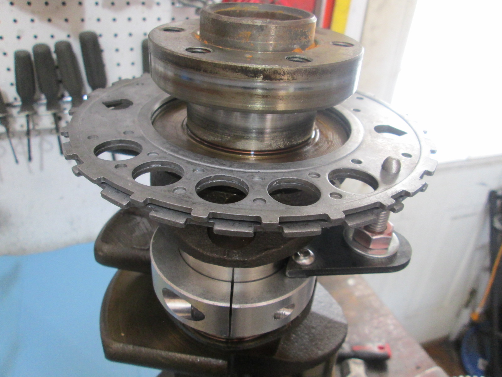
Here you can see the new reluctor will not fit the crankshaft due to the press fit:
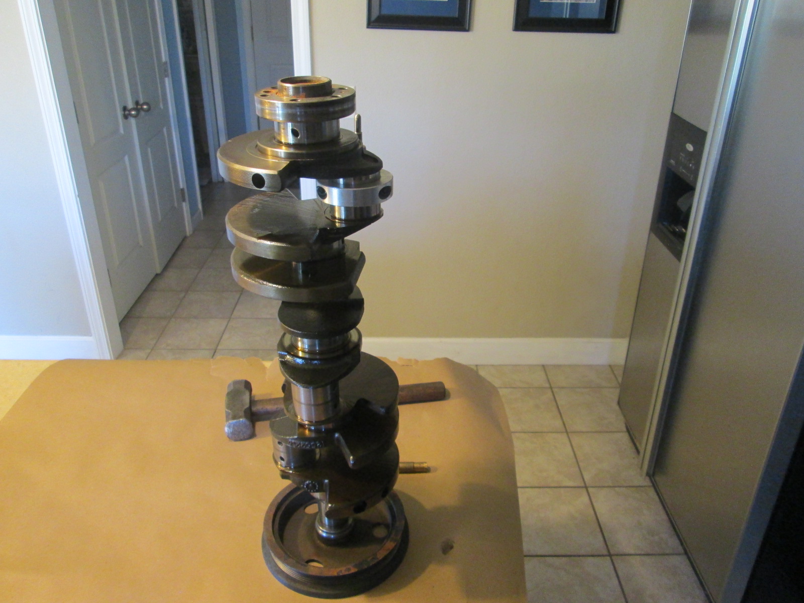
Set the new 24X reluctor with the flywheel side face up in the oven (so you don't need to flip it while hot), set the over to 500 degree broil and wait 20+ minutes. It was lunch time, so I cooked some pizza at 450, then swapped the pizza and reluctor wheel. Left the oven @ 450 while eating pizza, then turned it up to 500 broil while bring the crankshaft to the kitched and setting everything up for the hot placement.
Ready for the hot reluctor install:
I checked the temp of the wheel with a hand held IR temp tool and it was fluctuating between 510 and 525 degrees F. Using my welding gloves, pulled the wheel, lined up the reluctor hole with the pin from the tool and set the wheel down on the crank. It was plenty hot enough to set down on the crank fully w/o using any tools (literally just dropped into place). Took some pictures while letting it cool.
Set the new 24X reluctor with the flywheel side face up in the oven (so you don't need to flip it while hot), set the over to 500 degree broil and wait 20+ minutes. It was lunch time, so I cooked some pizza at 450, then swapped the pizza and reluctor wheel. Left the oven @ 450 while eating pizza, then turned it up to 500 broil while bring the crankshaft to the kitched and setting everything up for the hot placement.
Ready for the hot reluctor install:
The most important step is wife prep, which must be undertaken prior to moving any engine parts into the kitchen.
Will, great suggestion for those that have already gotten that modification in place. I've opted to stick with my factory-original SOH (single-overhead-household).
Originally posted by Will: The most important step is wife prep, which must be undertaken prior to moving any engine parts into the kitchen.
True! I did the wife prep a long time ago (Sara and I have been together for 20 years), so she is very used to me bringing parts into the kitchen for washing in the sink or baking in the oven.
quote
Originally posted by Bob2112: Your tool looks way better - genius! I hope if I decide to do this in the future, I can buy/borrow that tool from you.
Thanks! For the prototype the aluminum shaft ring cost $30 and I had to bore it, drill/tap 2 holes, and modify the metal tab. It worked, but I wanted to refine it a little before it takes up residence in the tool box. So I found some cheap ($9ea) aluminum bracket clamps that only needed to be bored, drilled and the end reshaped. Much nicer part to put in the tool box...
Haven't made much progress since last week due to other things needing my time. Heading to Indy today for Monster Truck Jam and hang out with my brother and nephews. Might make some progress on Sunday.
That is pretty cool! I will have to do more research on ratio and rotation to know if could be adapted for the AWD project.
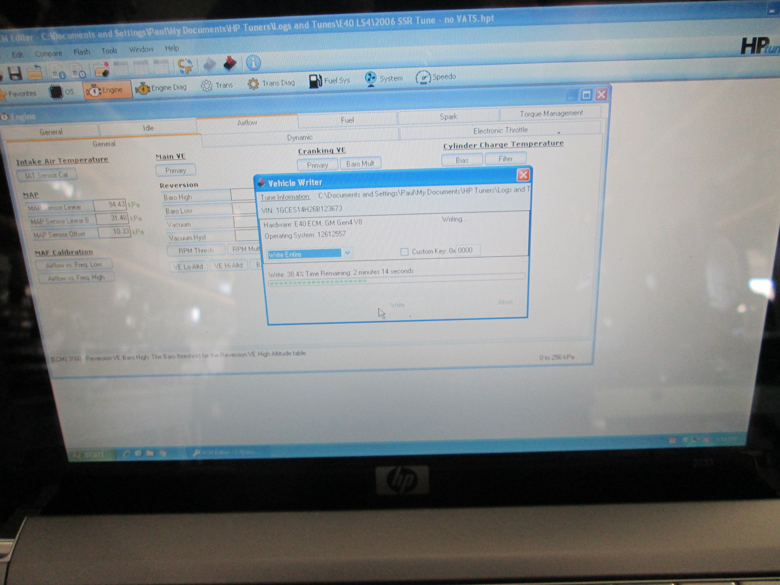
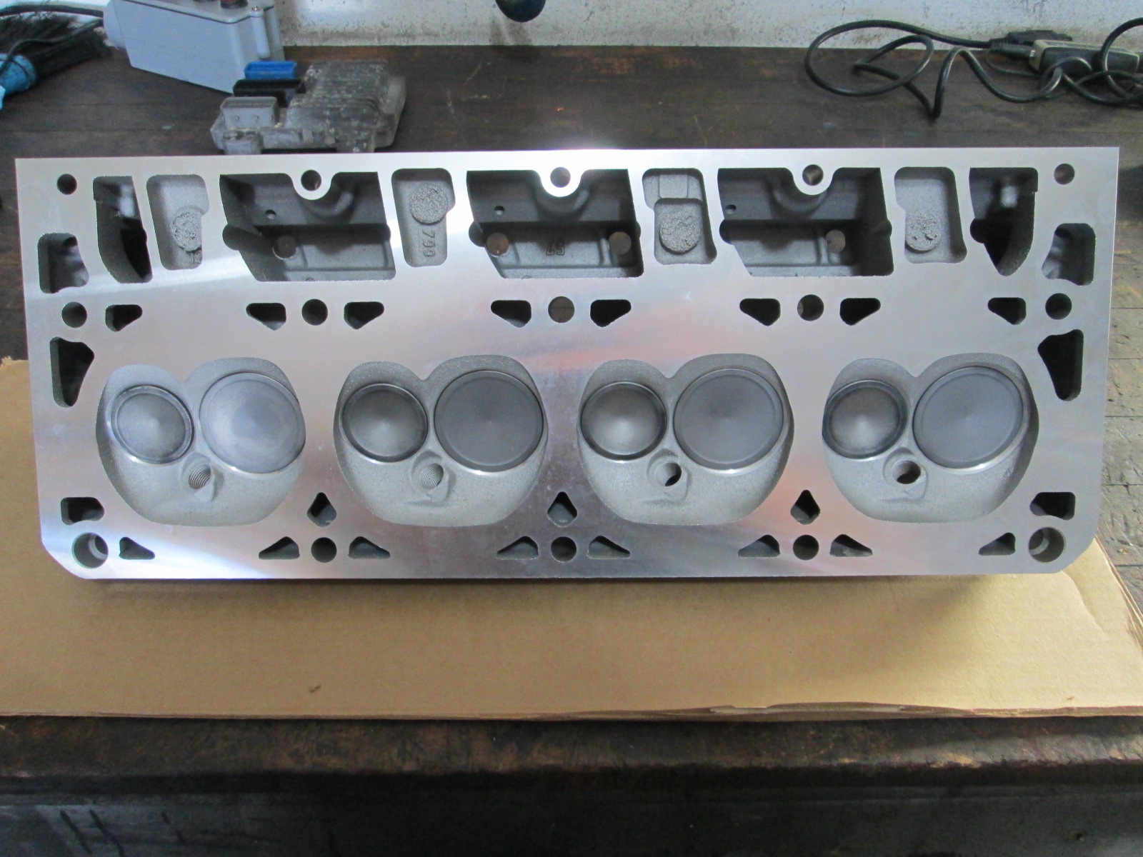
As far as progress on getting the LS4 back together... not much. Decided to send the heads off to TSP for stage 1 CNC porting to maximize NA performance in case I don't finish the turbo stuff in time. Did get the E40 loaded with the stock SSR LS2/T56 calibration, and have collection of E40 engine harnesses to start tearing apart.
I want to make a bench tune harness so I can start the programming work before the engine is in the car. I also want a simplified harness to allow running the engine on the cradle fixture. Then the harness for the engine in the chassis... I have plenty of parts/materials for all 3, but am forever short on time it seems.
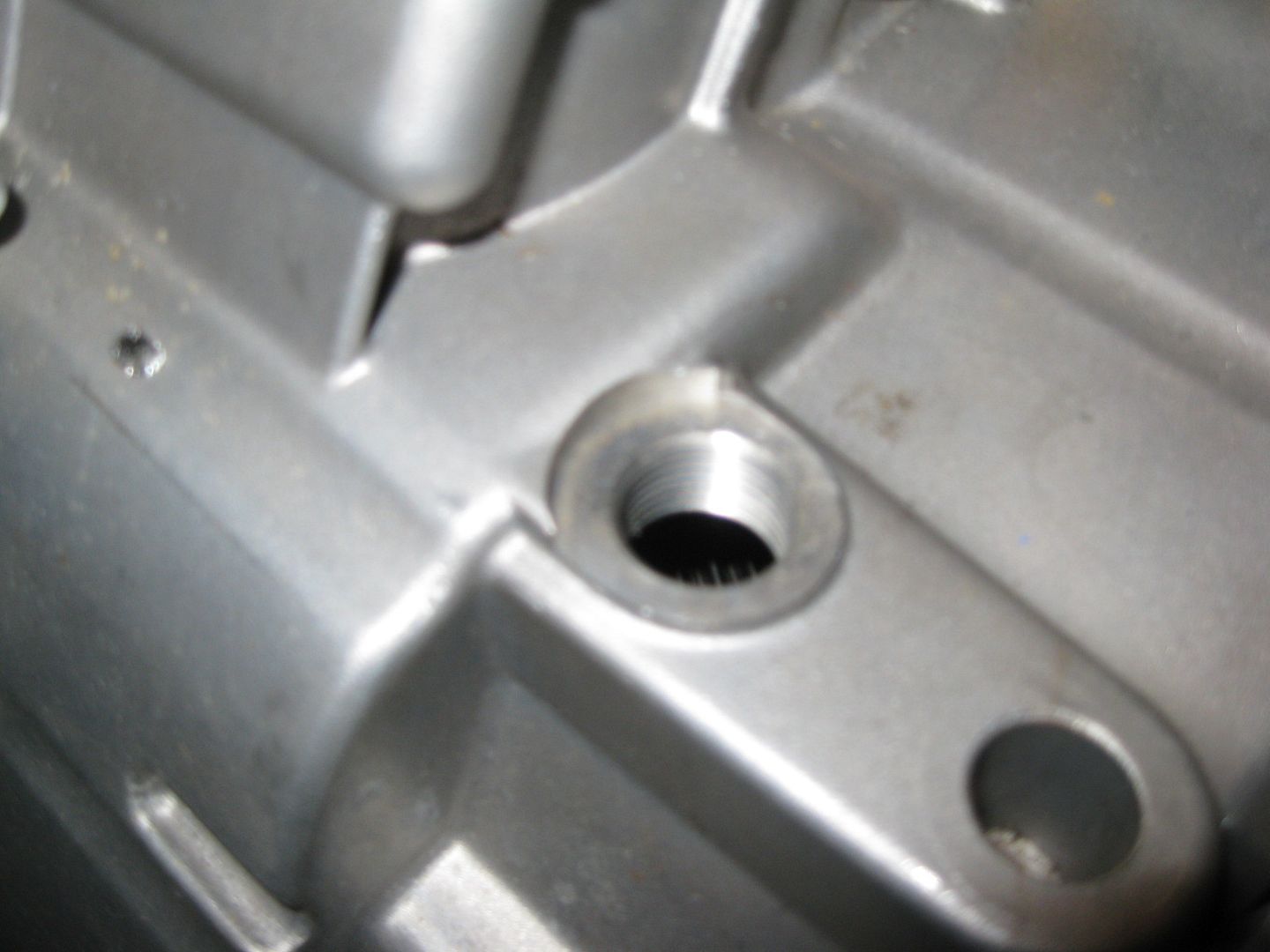
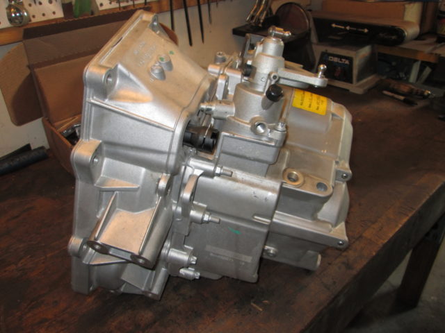
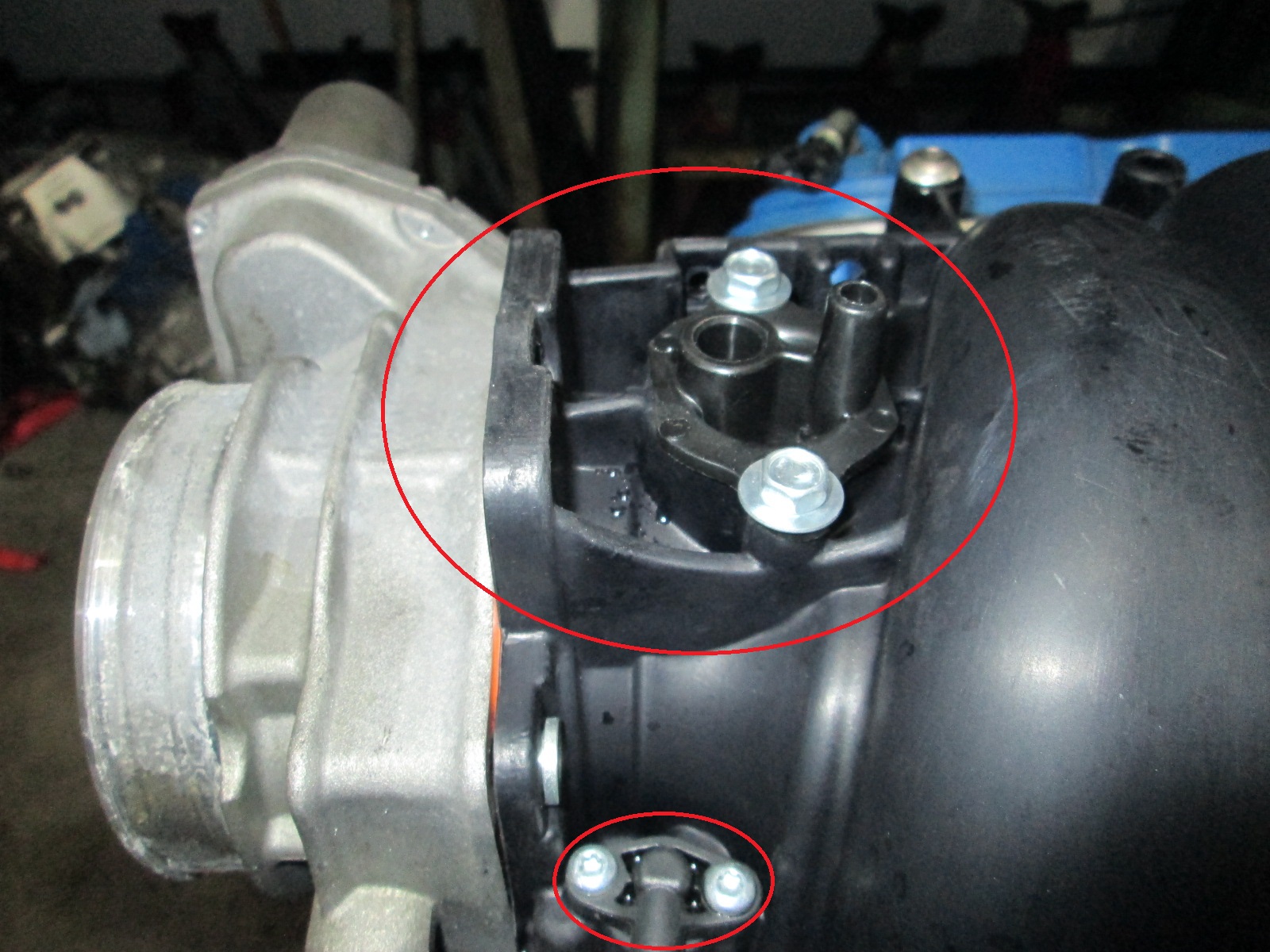
The oil fill hole in the F40 is threaded for a M18-1.5 plug... just like an O2 Sensor plug.
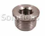
So I ordered 2 stainless steel ones ($12 shipped) like this to confirm:
I was thinking about this when I looked at my F23, and I thought it was worth mentioning, that the stock will caps typically have a vent path that allows for pressure equalization as temperatures go up and down, by installing an O2 sensor plug there, you remove the ability to relieve pressure, which could result in reduced seal life, and/or have oil leaks.
Just food for thought.
------------------ "I am not what you so glibly call to be a civilized man. I have broken with society for reasons which I alone am able to appreciate. I am therefore not subject to it's stupid laws, and I ask you to never allude to them in my presence again."
Originally posted by ericjon262: I was thinking about this when I looked at my F23, and I thought it was worth mentioning, that the stock will caps typically have a vent path that allows for pressure equalization as temperatures go up and down, by installing an O2 sensor plug there, you remove the ability to relieve pressure, which could result in reduced seal life, and/or have oil leaks.
Just food for thought.
The F40 is vented through a port w/ cap on the shifter assembly, so the the use of the stainless O2 sensor plug is a non-issue. The actual GM part is the same, just coated steel vs. stainless.
Originally posted by fieroguru: The F40 is vented through a port w/ cap on the shifter assembly, so the the use of the stainless O2 sensor plug is a non-issue. The actual GM part is the same, just coated steel vs. stainless.
10-4, that's good to know.
------------------ "I am not what you so glibly call to be a civilized man. I have broken with society for reasons which I alone am able to appreciate. I am therefore not subject to it's stupid laws, and I ask you to never allude to them in my presence again."
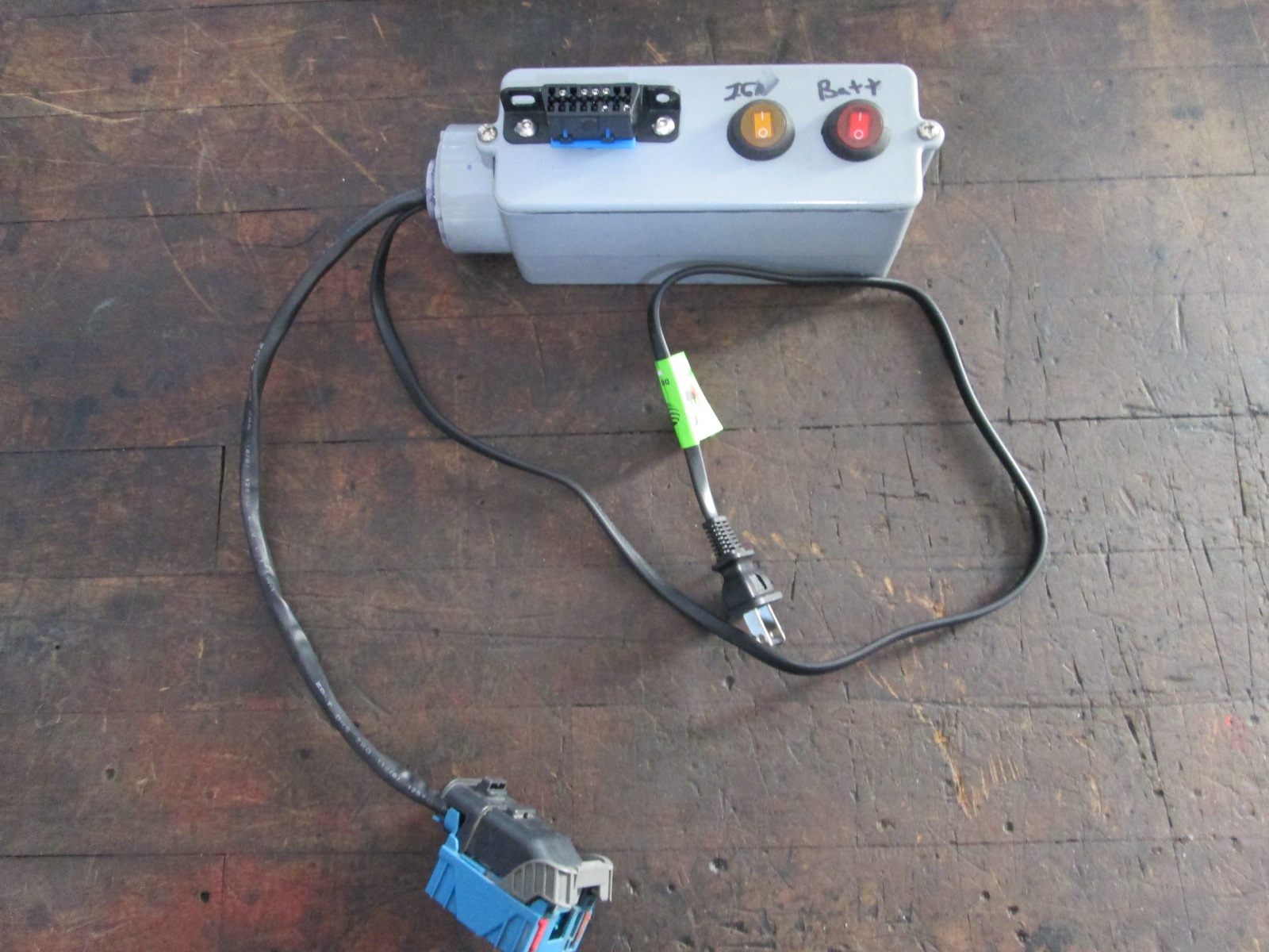
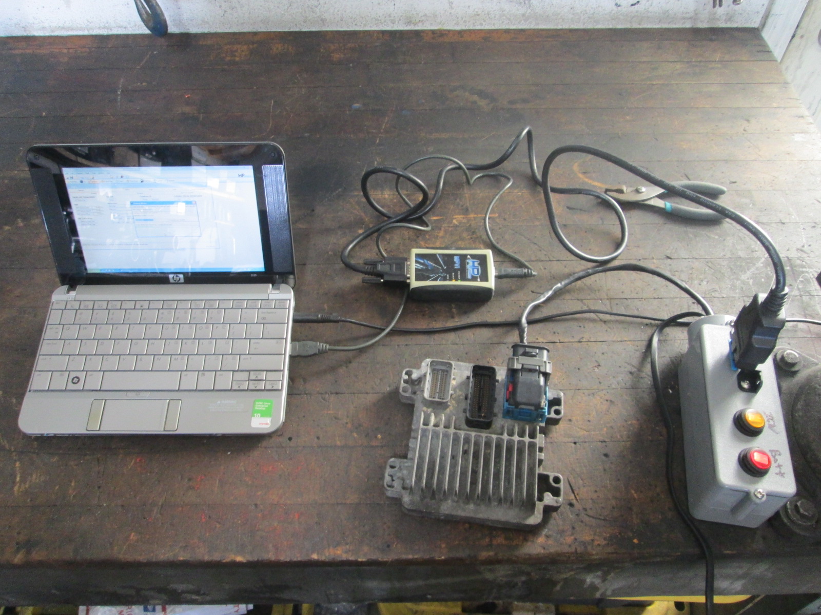
I finished making my bench tune harness. I used a Direct TV 12V power supply, 3A fuse, switch for Battery and Ignition, OBD2 connector, E40 ecm connector and a plastic conduit pull box. I probably have less than $50 in it. This download has all the wiring details for all the common ecms: https://download.efilive.co...rness%20Tutorial.pdf
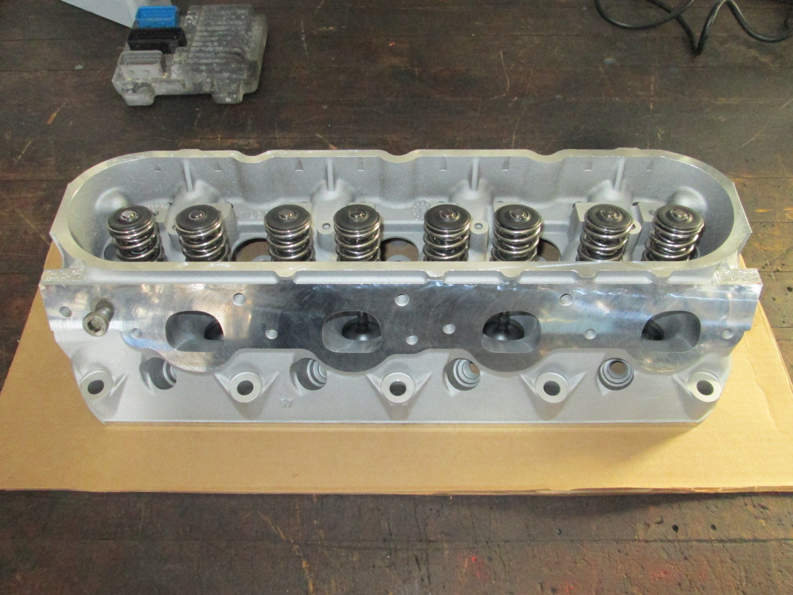
My heads also came back from Texas Speed with the stage 1 porting. The springs are BTR platinum dual springs for 0.660" lift.
I am planning to degree in the camshaft install the front and rear covers, and install the heads this weekend...
[This message has been edited by fieroguru (edited 04-10-2020).]
Originally posted by 85-308: I'd be interested in seeing your experience with degreeing-in the cam; also what size valves did the manage to fit? Thx for posting, as always. GP
Very first page of this build thread shows when I degreed in the DoD camshaft. The process this time will be very similar.
Stock LS4 camshaft specs: 197/197 .486/.486 @ 114LSA IVO (BTDC): -18 IVC (ABDC): 35 EVO (BBDC): 31 EVC (ATDC): -14
Previous 224/232 .564/.575 @ 113 LSA DoD camshaft IVO (BTDC): -3.5 IVC (ABDC): 47.5 EVO (BBDC): 46 EVC (ATDC): 5.5
New 219/222 .617/.596 @ 114 LSA camshaft. IVO (BTDC): -1.7 IVC (ABDC): 40.6 EVO (BBDC): 48.9 EVC (ATDC): -5.7
The TSP stage 1 CNC porting keeps the stock valves (2.00/1.55). Going larger on a 5.3 isn't recommended.
Heads installed and torqued down - I stuck with factory 5.3 head gaskets and GM bolts. Torqued to 22 ft lbs, 90 degrees 2nd pass, 70 degrees final pass.
Rockers installed and torqued. The CNC porting opened up the base of the rocker bolts in the intake ports, so I had to shorten the bolts (removed the unthreaded nubs from the ends) and installed the bolts with sealant.
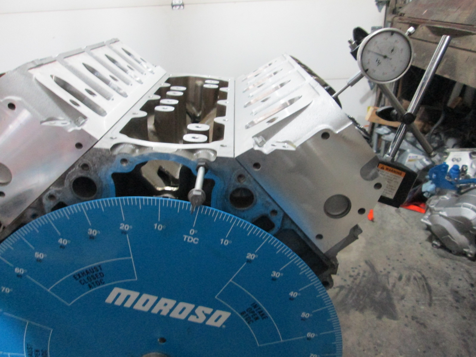
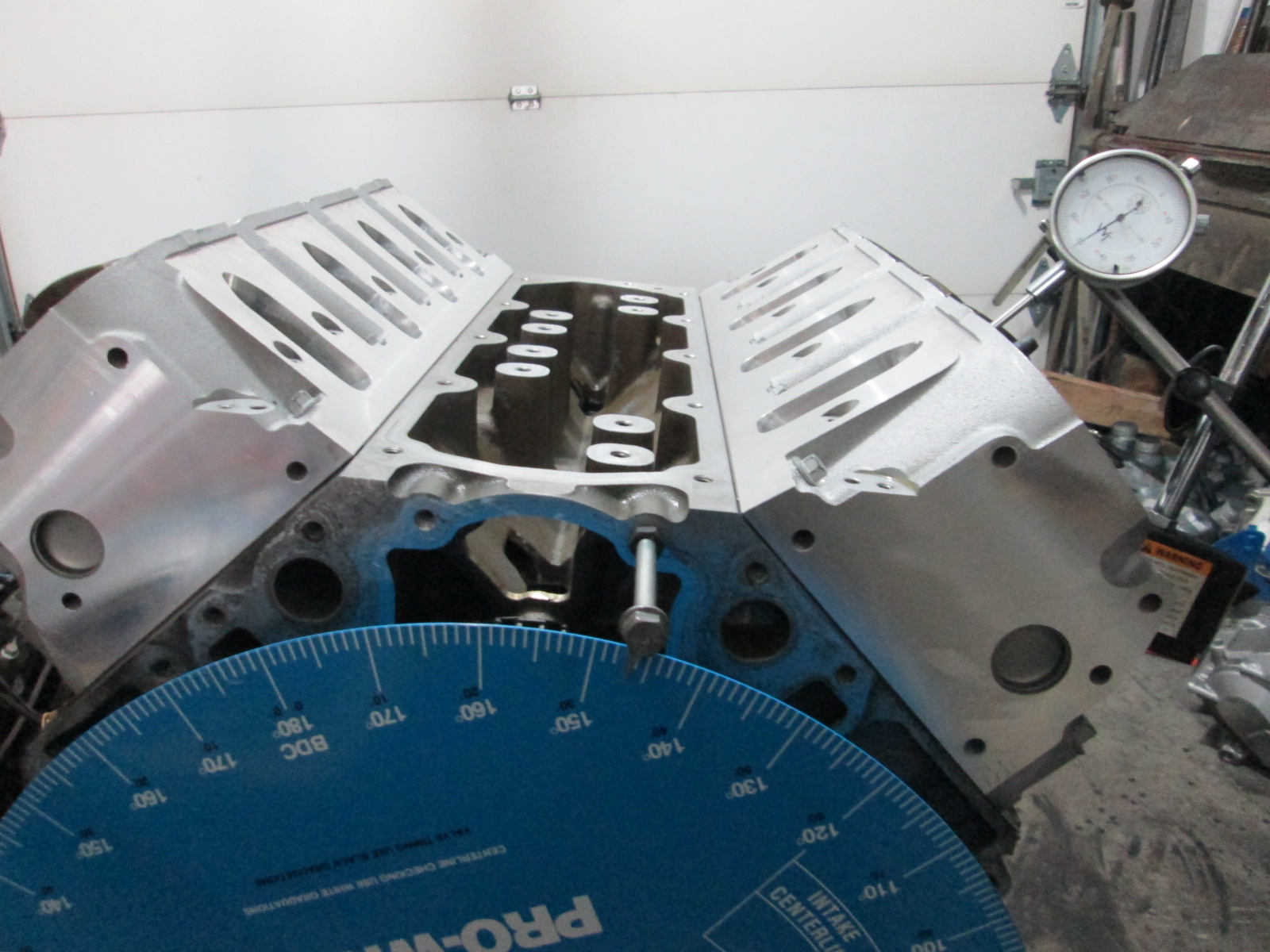
Camshaft degreed in with it installed dot to dot. The valve events were right where they are supposed to be. I will say the springs and lift are noticeable with hand turning the engine, lots of little spring pulses are each lobe goes to peak lift. Here are a couple of reference pictures showing the setup. Intake valve open @ .050" Exhaust valve open @ 0.050":
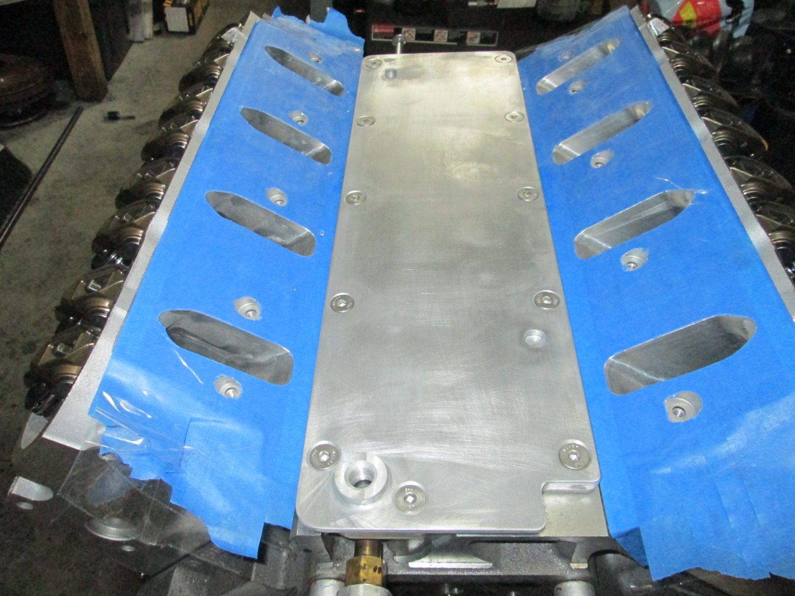
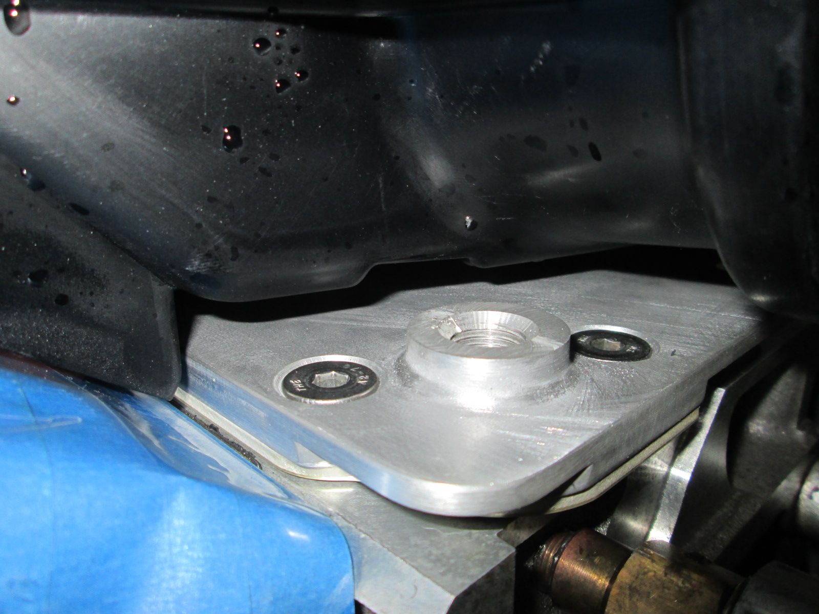
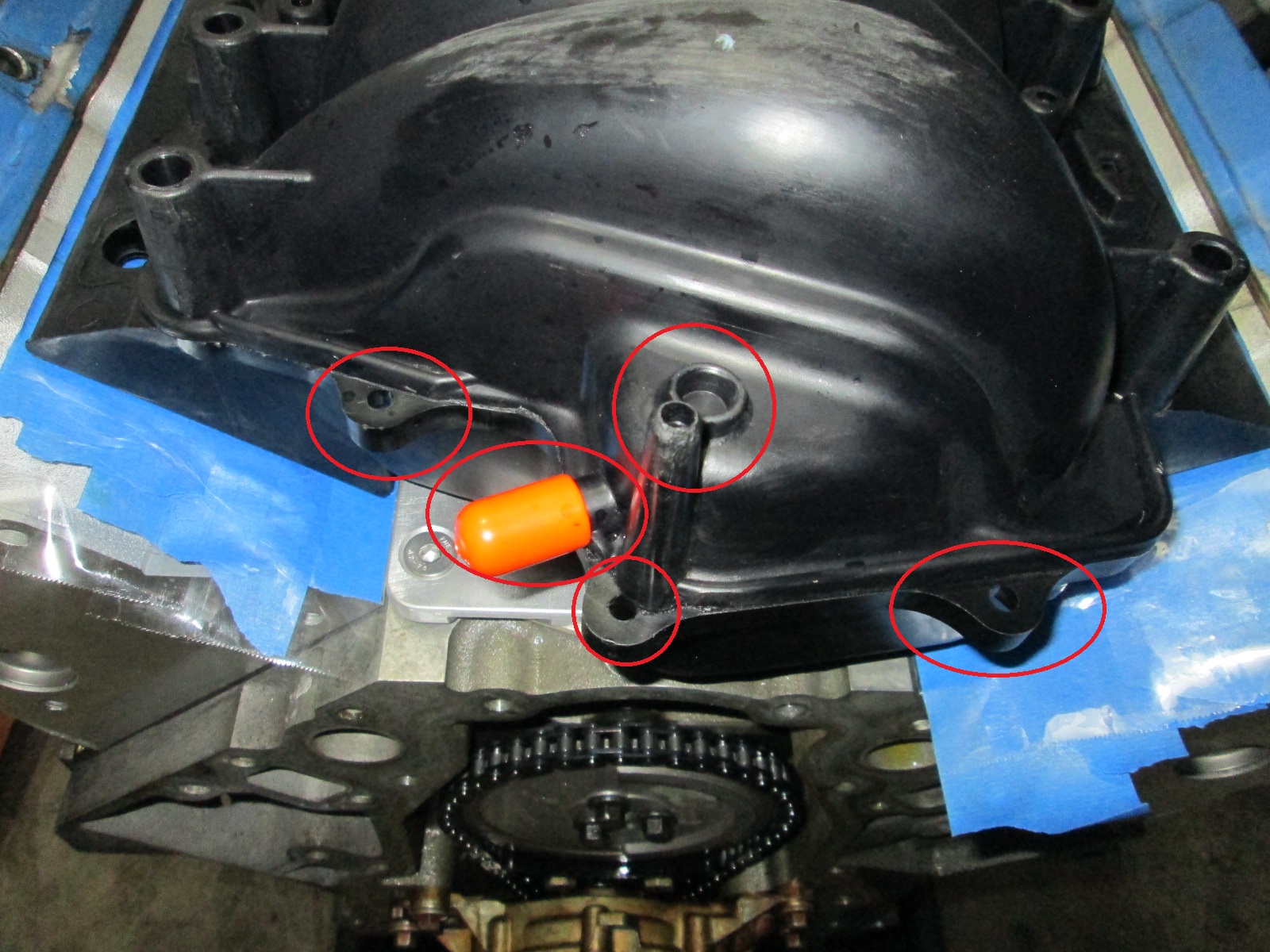
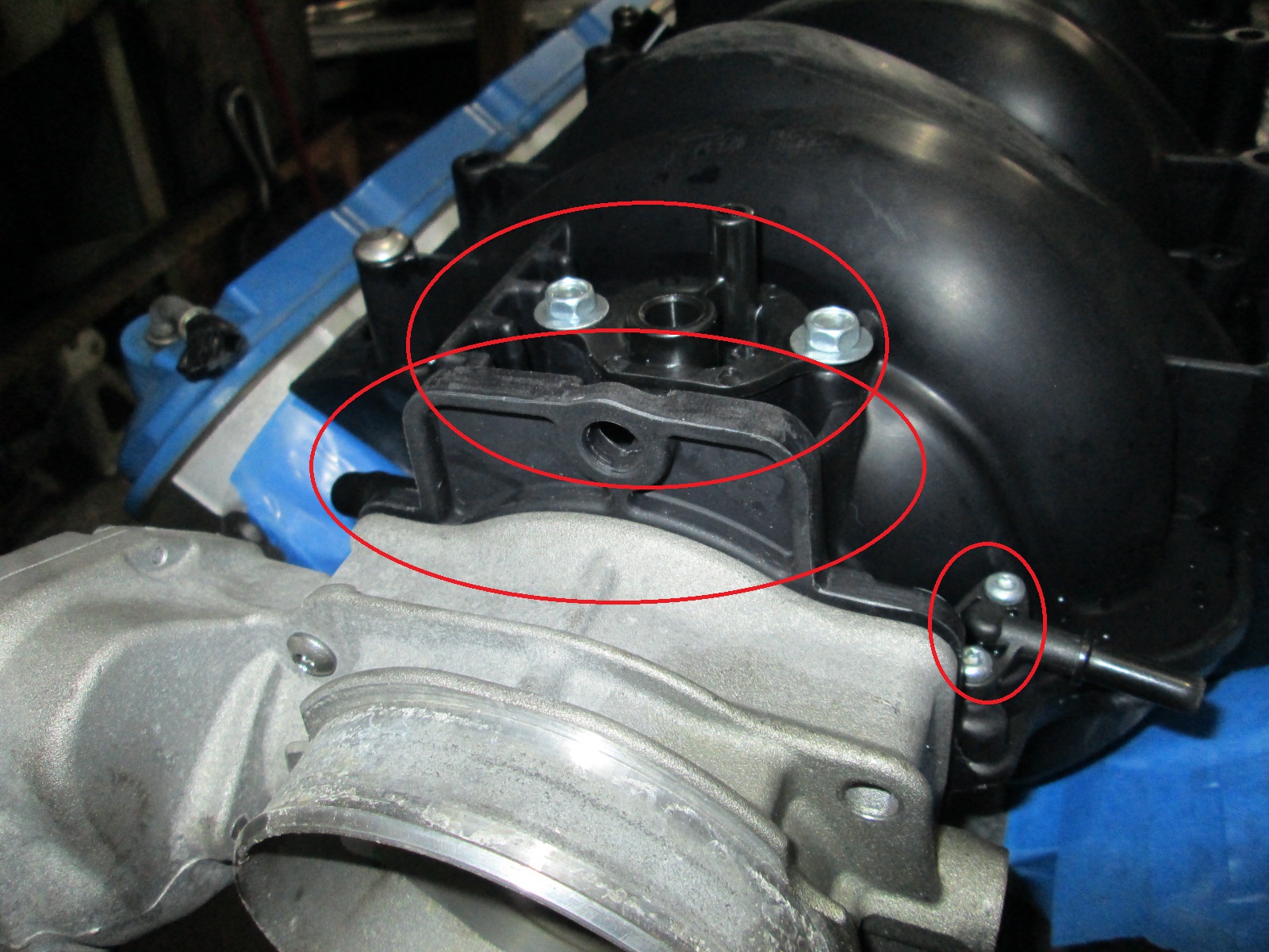
Since DoD was eliminated, I went with a factory LS2 valley cover, but I just had to make a few tweaks to it. First I cut down the OPSU boss about an inch and tapped it (might just plug this hole or use it for an oil feed to the turbo). The second modification was counter sinking all the bolt holes and adding stainless steel hardware, last modification was sanding down the sides to smooth the casting parting line flash. Not sure if this will be painted blue or aluminum at this point, so consider this a temporary install. This picture also shows the tape on the heads and the ports cut out. I will eventually used these to help verify port alignment with the intake.
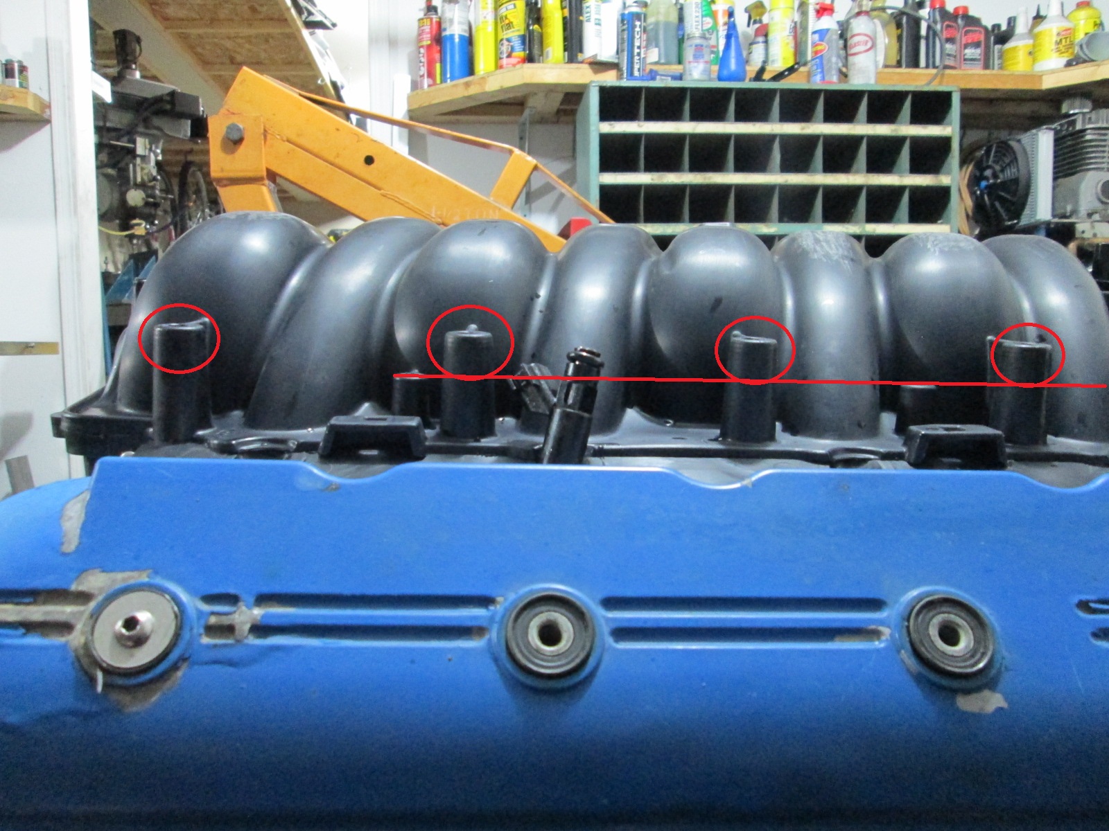
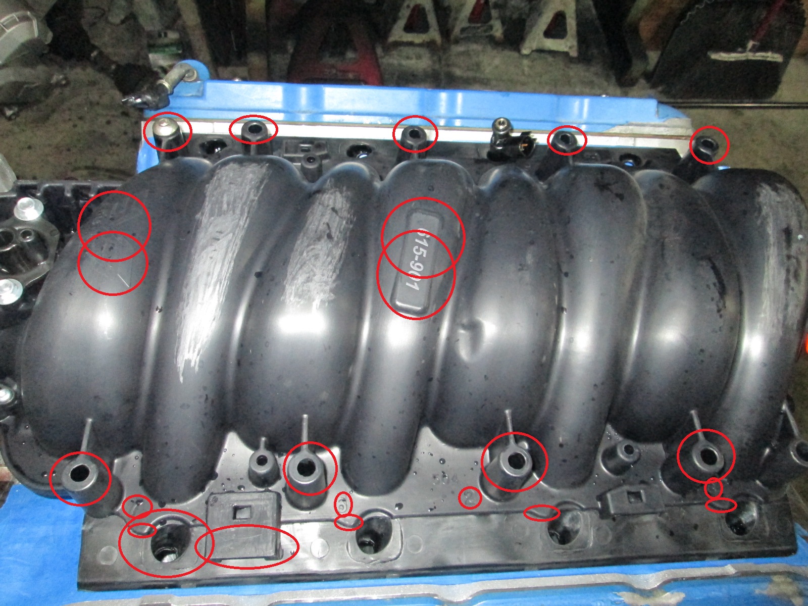
Then I started playing with the Dorman LS2 intake and making mental note of all the areas it will be modified, most of these are just to improve the visual appeal of the intake. There are several groups of modifications: 1. Intake bolt boss shortening. This needs done to reuse my modified bolts from when I did this to the original LS2 intake (they are too short with the stock height boss). The aftermarket fuel rail also wont fit on the injectors as it hits these bolt bosses as well.
2. Dorman probably figured that everyone runs an engine cover, so they literally wrote a book on nearly every surface of the intake they could. All of this has to go. There are also some areas were material extends and it doesn't have a purpose, so those need to go as well. Then there are some areas that would look better with the casting flash removed. Overall there just is a lot of smoothing in order. The scuffed areas on the runners have already had some text removed.
3. Universal usage fugliness... This intake is for the LS1 and LS2, so it has mounting provisions for the LS1 throttle body, the egr port, and alot of ugliness... All this will be cut down and cleaned up.
Once I address the aesthetic issues with the intake, then I can focus on some minor porting...
It was good to have some time away from work and customer orders to actually make some progress on my own Fiero!
I take it you are not concerned about boost going through the Dorman intake? I know it's my paranoia, just seemed like a bad idea to have something that normally saw ambient to negative air pressure to see positive pressure.
I take it you are not concerned about boost going through the Dorman intake? I know it's my paranoia, just seemed like a bad idea to have something that normally saw ambient to negative air pressure to see positive pressure.
People do it all the time, and push a ton of boost through them. the only failure I've seen, was a truck intake that all of the reinforcements were shaved off of.
------------------ "I am not what you so glibly call to be a civilized man. I have broken with society for reasons which I alone am able to appreciate. I am therefore not subject to it's stupid laws, and I ask you to never allude to them in my presence again."
Originally posted by Trinten: I take it you are not concerned about boost going through the Dorman intake? I know it's my paranoia, just seemed like a bad idea to have something that normally saw ambient to negative air pressure to see positive pressure.
I am only planning to run 7-10 psi boost. There has been 1 reported failure on the LS6 version (earlier version) at 15 PSI. It separated right behind the throttle body area at the seam. So far, I haven't seen any failures reported on the LS2 version, but time will tell. I want to keep the stock sleeper look and most of the other intake options either hurt low RPM toque, have also been popped, weight too much, or are too expensive.
The intake on my ecotec came from an NA 2.4 ecotec. People have boosted it to 20psi. Pretty good for a piece of plastic. After that, they may split open. Way more boost than I will ever use, I usually run at11psi max.
------------------ 86 GT built 2.2 ecotec turbo rear SLA suspension QA1 coilovers on tube arms
The 996 front diff includes a viscous coupling in the driveshaft. SOME type of center diff is necessary, as the Saab gear train does not include any. I've heard things that the 996 doesn't do a very effective job of putting power to the front tires... like YouTube videos of AWD 996's stuck in the snow without the front tires spinning... although the front diff is open so the video might not catch the other side spinning.
Originally posted by Will: The 996 front diff includes a viscous coupling in the driveshaft. SOME type of center diff is necessary, as the Saab gear train does not include any. I've heard things that the 996 doesn't do a very effective job of putting power to the front tires... like YouTube videos of AWD 996's stuck in the snow without the front tires spinning... although the front diff is open so the video might not catch the other side spinning.
My plan has always been to run a 1 way clutch in the drive shaft to the front diff. With the smaller front tires, the front will always over run (rotate faster than) the rear. When there is zero slip at the rears, the front just spin as normal w/o any power applied (they are effectively being pushed faster than the engagement RPM of the power). When the rears do slip (on hot dry pavement), and try to rotate faster than the fronts, the 1 way clutch will engage and send power to the front wheels. The fronts will then try to put an end to the wheel spin while helping to pull the car in the right general direction. One the rear slip subsides, then the fronts go back to their free wheeling... that at least is the thought/theory... Simple 100% mechanical AWD on demand w/o the typical binding in parking lot maneuvers.
Great looking setup, love the attention to detail. A few questions for my own LS4 build, I noticed you tapped and plugged the holes used for the DoD lifters. Is that required? When I remove my setup, will I have to tap/fill those as well? what about the o-rings that would normally be there, do I need to worry about oil flowing out of the holes?
Also, noticed you still have the oil fitting on your valley cover, do you need this if your using your oil adapter, the one that installs near the oil filter? I was under the impression that I could use a valley cover without the oil fitting by using your adapter?
Thanks in advance.
Rob
Rob, there are a lot of things I do that are definitely not required, some are to get a specific look (like all the mods to the dorman intake) and some are for personal preference.
Tapping the DoD pedastal port is one of those. As long as you get a valley cover with the built in o-rings to seal those passages, you will be good. There is another potential modification that might require me running a thinner valley cover, which might not be able to apply enough pressure to seal the DoD o-rings. Since I had the camshaft out, tapping them seemed like the practical thing to do and it avoids any potential o-ring failure 10-15 years down the road.
Keeping the OPSU boss is another one. You don't need to keep it. There are billet versions that have it completely blocked off, but I like using GM parts as much as possible, and pretty much every one of them has the OPSU. I shortened it so it doesn't get in the way anymore, but left enough material I could either put a NPT plug in it or use it for the oil feed to the turbo... not sure which way I am going, but left myself options for either path. If I need a thinner valley cover, then I won't even use this one...