When are you going to get the paint shining like it deserves? The car is a labor of love and it should look the part.
Who knows...
I would like to get it painted, but I still have 3 more body mods to complete. I also don't want it to be locked up in body shop jail for a year or more either.
So for now, I will just continue with more modifications/refinements and drive the wheels off it!
Long Hauled with Marty, his son Steven, and Jack & Joe. Also met up with several other Fiero owners and showed Alex4mula some pictures of the sub box he inspired from his build. Spent a fair amount of time talking about my car, and Marty and Joe helped field the many questions as well.
Only issue was some debris on the road between Indy and Joliet damaged the sidewall on one of the rear tires. They were 8 years old and needing to be replaced. Fortunately, from Joliet, we were headed to Ft. Wayne and Tire Rack has some rear tires in stock. So we nursed the car to South Bend, got new tires, and made it to the Ft. Wayne venue about 3 PM.
Also met up with some of the Haltech guys that were participating in the tour with their personal cars and they really liked the Fiero as well.
Overall is was a 1200 mile trip and the best tank of gas was 27.6 mpg. I checked the weight again as the same grain elevator, and it is still 2920 lbs, so more work needed on that front.
Now that the HRPT is over, I started with the WOT tuning. After about 6 WOT runs with the boost controller set at 15% duty cycle I am seeing about 3.5 psi boost. I should be within about 1-2% on the fueling with the latest tune revision. Now I can bump the duty cycle, and start coorelating % duty cycle to overall boost pressure, and dial in the fueling at higher boost levels. Not planning to go over 8psi.
The car has been to work 1 time this year, but I will be drving it daily for the rest of the summer.
Just been driving the car daily the past 2 weeks (truck hasn't moved).
Adjusted the End Of Injection Timing (EOIT) and saw a 2% reduction of fuel usage at idle - should be similar at cruise.
Part throttle VE is within +/- 2%, but can swing up to 5% between morning and afternoon driving (fuel and air temp caused), so I disabled closed loop & LTFT below 160 degrees (it was set to 32 degrees as delivered) and lowered the LTFT gain to 5% so the STFT can take care of changes due to fuel temperature w/o having the wrong LTFTs stored the next time the car is started.
I still need to insulate the hot air tube from the turbo to the intake. It is heat soaking too much and I see about 125 degrees in city driving - granted it was a 95 degree day.
Cut the cold start enrichment in half, since it is now running open loop and the supplied gains were much too high.
With the change of the cold start enrichment and the raising of closed loop to 160 degrees, I can start the car in the morning and go. Before I needed to let it warm up about 60 seconds, and feather the throttle more on the first 2-3 accellerations from a stop.
Roughed in the max throttle opening by RPM x Gear so that 1st and 2nd gear hook vs. spin (atleast at 15% wastegate duty cycle)
The car now has about 8,500 miles on it with the turbo, and about 2000 miles this year.
Waiting for a 195 thermostat to come in, then I will swap out the 180 in the car. Warmer engine temp should help with fuel economy and my quest to get to 30 MPG.
Still need to work on the cruise, front wheel speed sensor, and flex fuel... but free time has been limited.
I accepted a promotion to the Asset Manager (Plant Manager) position and will be covering my duties as the Engineering Manager until that position is filled. Anyone with significant engineering exxperience looking for an Engineering Manager position with a public utility in the middle of IL and surrounded by corn/soybeans, please send me a PM.
Just been driving the car daily the past 2 weeks (truck hasn't moved).
The car now has about 8,500 miles on it with the turbo, and about 2000 miles this year.
Waiting for a 195 thermostat to come in, then I will swap out the 180 in the car. Warmer engine temp should help with fuel economy and my quest to get to 30 MPG.
Still need to work on the cruise, front wheel speed sensor, and flex fuel... but free time has been limited.
I accepted a promotion to the Asset Manager (Plant Manager) position and will be covering my duties as the Engineering Manager until that position is filled. Anyone with significant engineering exxperience looking for an Engineering Manager position with a public utility in the middle of IL and surrounded by corn/soybeans, please send me a PM.
Where is the Tstat on your setup? is it under the filler neck?
edit:
I think I answered my own question. I'm guessing it's in here.
congrats on the promotion. Not so much on the dual responsibly. You're not selling anyone on being surrounded by corn.
[This message has been edited by KissMySSFiero (edited 06-30-2025).]
Originally posted by KissMySSFiero: Where is the Tstat on your setup? is it under the filler neck?
THe thermostat rests inside a rubber o-ring type seal and fits in the machined groove right under the coolant fill point. When the coolant fill is bolted down, it compresses the seal for the thermostat. This means that my LS4 coolant path is now like the SBC with the thermostat on the hot coolant exit from the engine vs. the cold coolant supply to the engine that typical LS engnes use.
quote
Originally posted by KissMySSFiero: congrats on the promotion. Not so much on the dual responsibly. You're not selling anyone on being surrounded by corn.
I have been covering 2+ postions for most of the 3 years I have been at this location, so it isn't anything new... I just know that a local food mfg has been posting for an Engineering Manager for 6+ months and my last 2 engineer postings took about a year to fill, so it will be a slow process.
If being in the corn doesn't sound appealing, how about no emissions testing within 2 hrs.
[This message has been edited by fieroguru (edited 06-30-2025).]
I have been covering 2+ postions for most of the 3 years I have been at this location, so it isn't anything new... I just know that a local food mfg has been posting for an Engineering Manager for 6+ months and my last 2 engineer postings took about a year to fill, so it will be a slow process.
If being in the corn doesn't sound appealing, how about no emissions testing within 2 hrs.
I live in Florida. No emissions anywhere around, and you may taking a beating if you suggest it. Nowhere in FL is more than 74 miles from the ocean. Negative: We have a few crazy people and hurricanes. We have 7-8 engineering req's open for my program alone. We're always understaffed. But at least we're not underpaid, most of FL is. My last job took a year to find a suitable replacement for a Communications systems engineer.
How's product development for your water pump and accessory drive coming? Is it something you're still considering selling?
I'm currently running the SC3800 in my choptop but I'm wanting another 100HP.
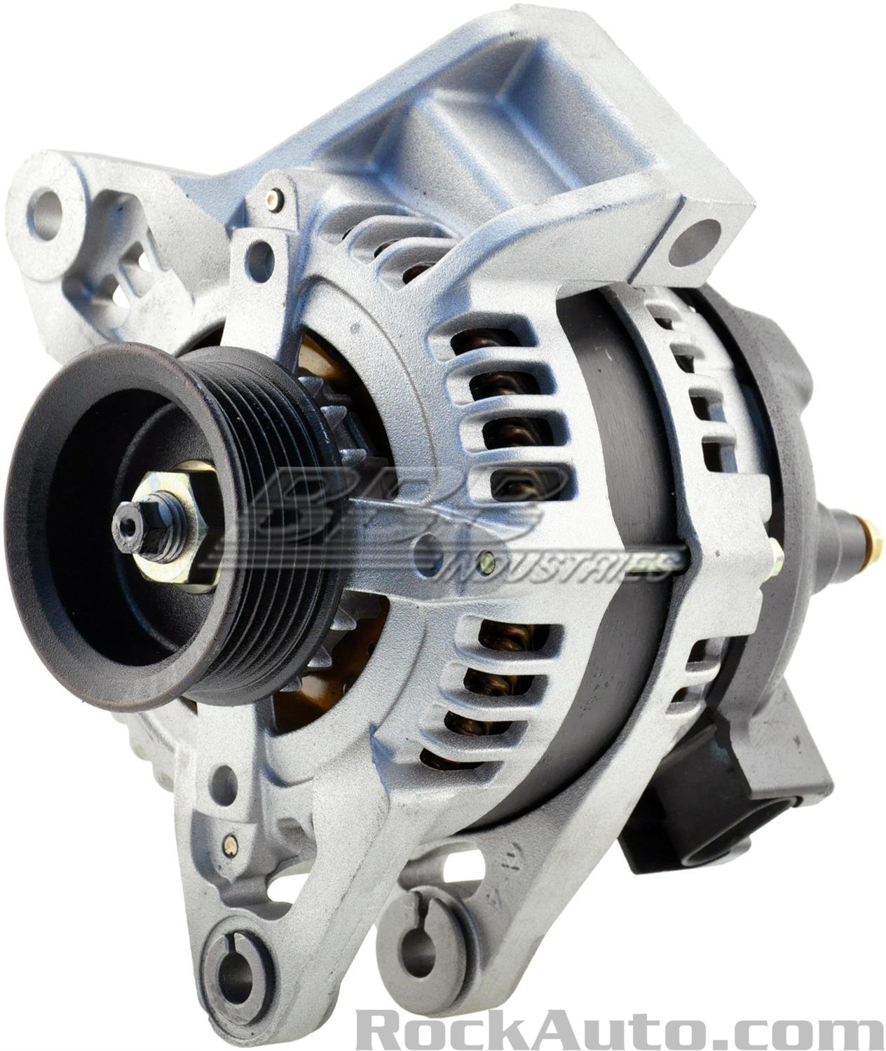
I found an alternator that may work for a flipped cantilever setup for the LS4 but I'm not a big fan of the look and worry about belt squeal.
I think I can use aluminum plate and spacers welded together. I should be able to pivot the alternator for tension.
Originally posted by KissMySSFiero: How's product development for your water pump and accessory drive coming? Is it something you're still considering selling? [/IMG]
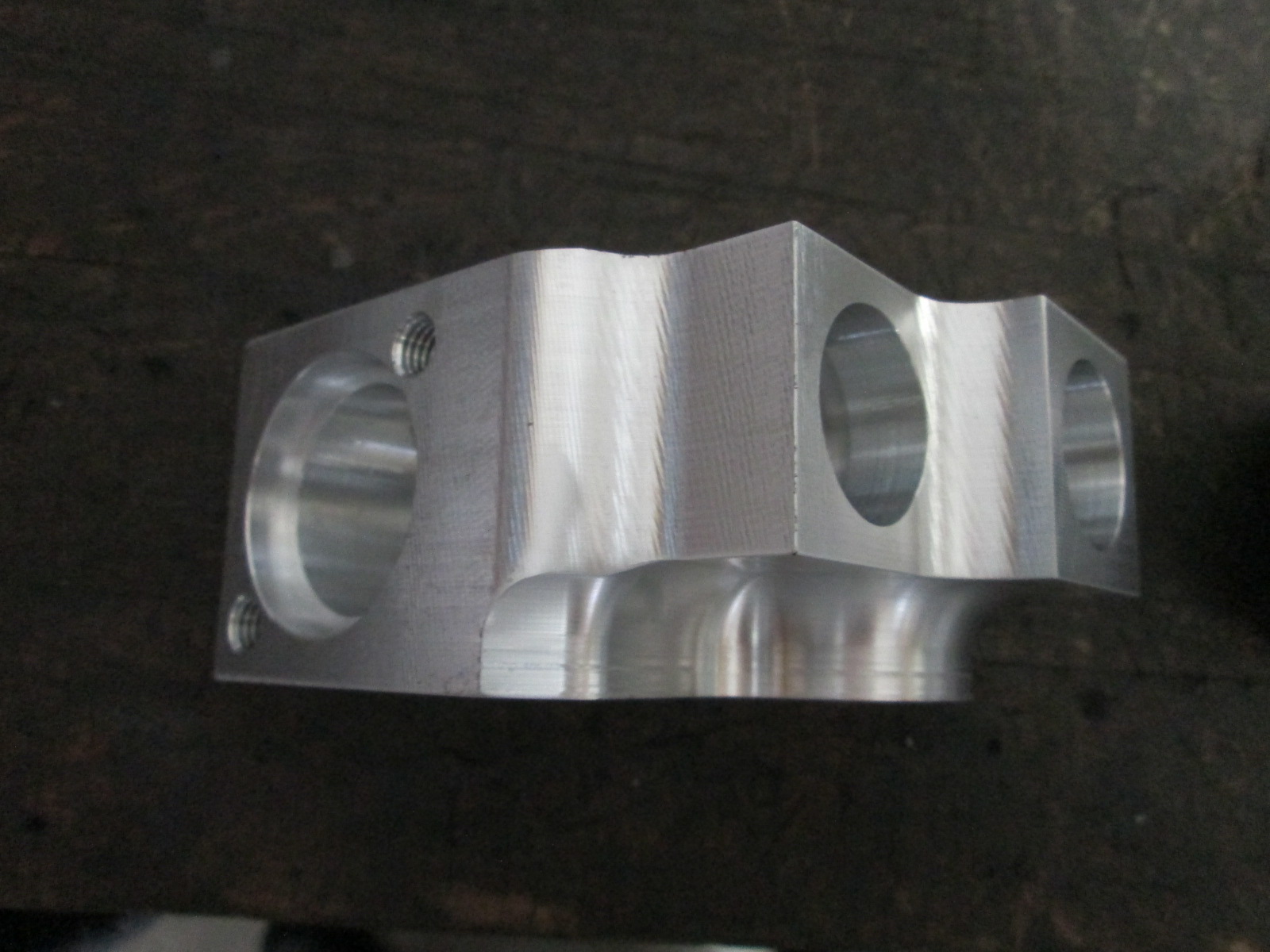
Slooooooooooooooooooooooooooowwwwwwwwwwwwww. I need to finish my CNC mill and learn 3D CAD to bring it to market.
The likely price point for the water manifold will be in the $500 to $700 range and the Summit Racing version is $199. Add in another $500 to $700 for the custom water pump, and the market starts to become very, very small. So these parts might just be something that makes my personal swap unique.
Once the CNC mill is operational and I can design parts in 3D CAD, I am sure my motivation will be more towards custom knuckles front and rear as I want them for my car.
quote
Originally posted by KissMySSFiero: I found an alternator that may work for a flipped cantilever setup for the LS4 but I'm not a big fan of the look and worry about belt squeal.
I think I can use aluminum plate and spacers welded together. I should be able to pivot the alternator for tension.
Yeah, after having the AC and Alternator down low and hidden for 12+ years, I am not a fan of the cantilevered alternator setup, but it is by far the most common method utilized for the LS4 swaps. In this thread I played around with the concept and found a tensioner solution so the alternator could be rigid mounted. https://www.fiero.nl/forum/...1/HTML/094409-2.html
Just make sure you can install the belt without having to remove the alternator supports.
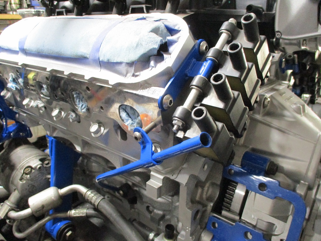
Cruise control now works through the stock 1988 Pontiac Fiero cruise stalk!
Several must haves that are burried across several Haltech technical guides:
DBW
Vehicle Speed - from a wheel speed input
Brake Switch wired into ECU
Gear detection or neutral switch
If Manual Transmission - Clutch Wired into ECU
1 or 2 input wires, must carry all the signals, voltage or resistance must vary based on resistors for each circuit
Now my Fiero did not have stock cruise, but I added the stock cruise stalk. So all the wiring terminations start at the clutch switch, brake switch, cruise stalk, 203, and Haltech ECU and Haltech 12 I/O Expansion module. For all the Haltech connections, I list the pin location. It is starts with an A or C it is the Haltech ECU, if it is IO12 then it is a pin location the expansion module - many of these could originate at the ECM depending on how many I/O you have:
Now there are a couple gotchas in this chart.
VSS Input: You will need to know the teeth count per 1 revolution for your VSS (F40 3.091 Final Drive = 68 teeth) You will also need to know the rotations per mile for your drive wheels (275/35/18 rear tires = 815 rotations per mile) The field for DriveShaft RPM Sensor - Number of Teeth is maxed at 50, so just enter 50 as it really does not matter.
The key is the Drive Train Sensor - Pulses/Mile = this is # VSS Teeth for 1 rotation x # Tire rotations per mile. For my setup with the 3.091 final drive it is 68 x 815 = 55,420. From there you can bump it up and down to make the ECU match GPS.
Now you have the Vehicle Speed into the ECU, but it needs to get to the Fiero Speedometer.
VSS Output: The Rebel LS does not come with a VSS output, so you have to make your own using one of the Generic Outputs. ON this page, you give the output a name = "Speedometer Output", select the signal type = "Frequency", and set Mode = "Table"
Next is to setup the "Frequency" table. We need to know the frequency (cycles = pusles per second) for a 4000 pulses per mile (most older electronic GM speedometers need a 4000 PPM input) @ 100 miles per hour.
4000 cycles/mile x 100 miles/hour / 60 minutes/hour / 60 seconds/minute = 111.11 hz @ 100 mph. This output is linear for all speeds, so some simple math and you get this table:
Now we have to assign the "Output" to a pin location and configure it:
Working Speedometer: Now that everthing is done in the Haltech for the speedometer output, it still didn't work for me. So I added in the typical speedometer buffer circuit that is needed for any OBD2 ecm to drive the Fiero speedometer. It is shown at the bottom of this schematic. With this circuit between the Rebel LS Speedo output and pin G on the 203 connector, the speedo will now work:
Once you have a working speedometer, now you can start working on getting cruise to work.
Cruise Speed Reference: From what I gather, the drivetrain speed within the ECU is not good enough for the Haltech speed signal for cruise, so I enabled a Left Rear Wheel Speed Sensor. You don't actually need to install a wheel speed sensor, you can "T" off the VSS Output signal going to Pin G of the 203 (and your speedometer) and send it back to the Haltech ECU once you have setup a SPI input for it.
LR Wheel Speed Input: Basically just turn on the Left Rear Wheel Speed toggle and enter "4000" pulses per mile since that is what we set the output driving the speedometer to.
I used an SPI input, set it for "Digital - Frequency", Edge Select = "Falling", Sensor Type = "Hall Effect", Pull Up = "Disable"
This should get you a working wheel speed for cruise.
Gear Detection: Since the F40 is a manual transmission, I need to enable Gear Detection: First thing to note is that the FWD F40 6 speed manual didn't make the cut in the available lists of transmissions (neither did the 2005-2009 LS4 for that matter - L33 FTW), so I used a T56 manual. Transmission Type = "Manual" Gear Detection Type = "Gear Ratio" Funtions = Toggle "Gear Ratio" to the ON state
Since the F40 has the VSS on the differential teeth, I went ahead and chose the km/hr per 1000 Engine RPM. From there you then have to calculate (or use the calibrate function for each gear) Formula is: 1000 RPM /(Gear ratio * Differenial Ratio) * (Tire Dia (in) * 3.14 / 12 / 5280) * 60
Now the ECU should know what gear the transmission is in.
Brake Pedal: The brake pedal is easy as the brake wire in the pedal harness just needs spliced into the +12V from the brake switch on the brake pedal.
Clutch Switch: The clutch switch is an available function, so it needs turned on and assigned to an input. I chose to use an AVI input for this. Since I was using a 5V feed for the clutch and cruise inputs, the clutch sends a 5V back to the ECU when it is pressed. This could have just as easily been a 12V circuit. Input Mode = "State/Switch/Button Input", Switch On Voltage = "4.0V", Switch Off Voltage = "2.0V", Pull Up = "Disable"
Cruise Control: Now at long last we are ready to setup the actual cruise control inputs. This takes some pre-planning and some trial and error (at least for us non-electrical engineering types).
You can use either 1 or 2 inputs for the cruise commands. The 2nd input can only be to Engage/Disengage cruise All other cruise commands need to share the same input and have varying voltages based on which button was pressed. Since I was using 5V for the cruise commands, I used the 2nd input for Engage/Disengage as it was one less resistor and voltage splits I would need. Here is the first Cruise table, most of this is pre-populated. The one thing I did change was the Maximum Wheel Speed Difference = 100 mph. This was due to troubleshooting my front wheel speed sensor for traction control. If you have any other wheel speed sensors that are not working (and calibrated), then you need to include this setting or Cruise will not work.
The cruise buttons page really had me stumped for a while. For a mid 80s Fiero, Input Type = Analogue - Voltage Then you need to setup available cruise commands. Typical 80s GM application will just have 3: Set/Coast -, Resume/Accell +, and Resting Position. Resting position really isn't a command, but an absence of a command. Now Set/Coast - & Resume/Accel + will need to come in on the same wire, so before they join, you need to add in a couple of resistors. Since I have 5V to work with, I installed a 220k Ohm resistor on the Set/Coast - wire and a 1M Ohm resistor on the Resume/Accel + wire. Once wired up, you press the lever for the command, then press calibrate. Then move to the next. Last while not pressing anything calibrate the resting position.
Here are the input configurations. The separate input toggle is switched on. Input (these are the cruise commands on the buttons page), is an AVI, Pull Up = Disable. The Separate Engage Input = AVI input, Switch ON Voltage = 4.0, Switch OFF Voltage = 2V, Pull Up = "Disable", Button Mode = "Momentary"
It was a fair amount of work to get figured out, but having working cruise is AWESOME!
[This message has been edited by fieroguru (edited 07-09-2025).]
Thanks for much for posting all of this. I probably won't be using Haltech now that I've spent a lot of time learning MegaSquirt on my Mustang. But, the logic should be very similar for other systems. This should be a huge help to me and I'm sure several others. Great work as always! And I'd be in that small market for your mechanical water pump solution for the LS4.
Haven't been doing much but driving the car. Took it to WI for a work trip a couple of weeks ago. This past weekend increased the boost duty cycle to 35% and did about 4 WOT runs between 2nd and 3rd gear and dialed in the 130 to 150 kPa and 3000-7500 RPM range.
I had ordered this a couple weeks ago and today spend 10hr in the truck picking it up.
Laser cut, 5/16" thick, 4'x6' Fixture/Welding table, with 5/8" holes on 2" centers, and alignment tabs between all the pieces. Going to be a lot of clamping and welding to fully assemble this. Probably will add a tool box and some shelves between the legs.
I have been wanting one of those for years. I envy you Guru.
Me too! I was stalking several sellers and narrowing down my selection for the past couple of years. I am in the middle of an equipment change in the garage for better space utilization and nicer equipment, so this was an opportune time.
Deciding factors for this specific table ($2,300 for the kit) + 10 hrs of driving:
1/4" or 3/16" thick was a lot cheaper, but 5/16" was a thin as I wanted to go.
Single piece top - many of the cheaper options would have required bolting 2 or 3 tables together.
Creative/artistic design - many others just used blocks with rounded corners.
This table only has the locating tabs along the outside edge and are flush. No welding is needed on the top of the table, and all assembly welding is on the bottom side.
4' x 6' table is a custom size for most, so needed a supplier to that would do custom sizes
Today I picked up a variety of clamps, all-thread and other parts to clamp the supporting strutcture to the table top. I will likely start the welding this week.
This table will replace my current 63 x 57 x 36" tall metal table as well as my old 4" I-beam cradle fixture.
The 36" pexto shear I had for 30 years and 48" brake I had for 20 years have already found new owners:
Looking to sell this 6,000 lb scissor lift:
Also, looking to sell the LS4 4T65e-hd that has been hanging around the garage for 10 years. It is a factory rebuild, but unknown condition or miles (I have another one, so I don't need 2).
Back to the engine, I thought you might want to extend your dipstick tube to make it easier to read. I installed a Saturn S car dipstick tube into the LS4 tube and extended it about 18" and massaged it around toward the back of the car and up under the throttle body to make it easy to reach since I have a fastback with a hatch from Archie that made it almost impossible to reach. I used a Motoforti Engine Oil Dipstick Indicator, Oil Dipstick Replacement, for Chevrolet Express 2003-2014, Metal Plastic, Yellow from Amazon and had to shorten it a couple of inches but it makes checking the oil a breeze now. Just thought you might want this info. It looks factory made.
Back to the engine, I thought you might want to extend your dipstick tube to make it easier to read. I installed a Saturn S car dipstick tube into the LS4 tube and extended it about 18" and massaged it around toward the back of the car and up under the throttle body to make it easy to reach since I have a fastback with a hatch from Archie that made it almost impossible to reach. I used a Motoforti Engine Oil Dipstick Indicator, Oil Dipstick Replacement, for Chevrolet Express 2003-2014, Metal Plastic, Yellow from Amazon and had to shorten it a couple of inches but it makes checking the oil a breeze now. Just thought you might want this info. It looks factory made.
The stock LS4 dipstick works quite well with a slight relocation of the bracket. I like it exiting where the coils are. Plus is less parts you have to buy for an already espensive swap.
Lots of welding on 90+ degree days, but now all the welding on the table and bottom supports is complete. Then started working on the leg modification. Space is always tight around the garage and while these base plates for the legs are nice and will allow casters to be installed, they take up too much space since I do not plan to us casters.
Here is the new simplified design:
The plan is to run an adjustable foot with a 5/8" threaded rod through a threaded coupler that is about 2" long.
The threaded coupler is going to have the hex turned off about 1/8" from both ends, then sandwiched and welded between these two plates, then the two plates will be welded to the leg.
All the welding for the table is complete. Here are pictures of the legs:
All the legs have one of these adjusters:
On Sunday I am going to pick up a new DA sander (foam pad disentigrated on my old one), sand the sides of the table, and then paint the bottom and sides to help keep rust to a minimum. The top will stay bare metal and I will likely put a skim coat of oil on it.
Also, the 63" x 57" x 36" tall metal table went to a new home today, so atleast there is room for the new one now!
[This message has been edited by fieroguru (edited 08-23-2025).]
For a few more days, the 6,000 lb scissor lift will be the shop table. Hoping to move on the scissor lift to a new home about the same time the table is dry and the legs are back on it.
[This message has been edited by fieroguru (edited 08-30-2025).]
Fab table is right side up and fully assembled now!
Not a show quality paint job, but good enough for a work table. I still need to use the DA sander on the top to remove some over spray and surface rust and then coat it with some oil. It is 39" from the floor to the top at the lowest setting. It also weighs 620 lbs.
[This message has been edited by fieroguru (edited 08-31-2025).]
Here is the caliper, bracket, and mock up rotor installed: Now waiting for drilled/slotted rotors to be delivered.
Within my rotor database, there are close to 350 different rotors. If I filter with a rotor thckness that allows retaining stock 88 calipers and overall rotor diameter between 12.0 and 13.0", there are 22 applications.
The lightest is the 12" 88 C4 front rotor @ 13.5 lbs and has 1.12 lbs/inch of diameter. The nearly 12.5" rotor I am switching to is the 2nd lightest @ 14.0 lbs and has 1.13lbs/in of diameter. The 13" traverse rotor currently on the rear is 1.39 lbs/in of diameter.
With this change, I will drop some rear, unsprung & rotational weight, and likely allow fitment of a 16" wheel (without needing to modify the calipers) for drag racing.
While I have the car down (no longer than 2 weeks), I am mocking up some intercooler options. I have both A2A and A2W setups to play with. The A2A is the most weight efficient, but likely less effective than the A2W setup.
Below is one location for the A2W. It will require some sheet metal trimming/denting to get it level. I will have to add another bleeder port to get all the air out of it. It is also the absolute shortest length of charge pipe. Doesn't really go with my stealthy vibe, but I could paint it black (and insulate it) so it blends into the engine bay and is less obvious. After a 2 hr drive at interstate speeds on a 70 degree day, both decklid vents are 119 degrees. On the same trip the IAT was showing 105 degrees most of the time, so a slightly cooler location would also help.
Originally posted by fieroguru: Below is one location for the A2W. It will require some sheet metal trimming/denting to get it level. I will have to add another bleeder port to get all the air out of it. It is also the absolute shortest length of charge pipe. Doesn't really go with my stealthy vibe, but I could paint it black (and insulate it) so it blends into the engine bay and is less obvious.
The car wasn't fast enough without the intercooler?
With a 3D-printed plastic insulating case, this could be made to look like an air filter enclosure.
Originally posted by pmbrunelle: The car wasn't fast enough without the intercooler?
Just trying to max out the combo. Already have 450 walbro, 1050cc injectors, and a 9 1/4 twin disc clutch. With the current rear wheels/tires, at 7200 rpm the car will top out at 135 mph in 3rd gear. I have reached this level many times while tuning, I just want to get there quicker. Not really a 1/4 mile enthusiast, but I do have the opportunity a couple times of year to run w/o normal NHRA tech requirements.
1st and 2nd gear are traction limited (and I will be limiting boost by gear and throttle opening by RPM), so to minimize ET it needs to pull as hard as possible in 3rd gear from 85 to 135.
4th gear would only be needed for standing mile events, but within an hour is a 2000hp dyno capable of 200 mph, and 7200 in 4th is 187 mph. I can rent this for 4 hrs for $500, which is my plan when I am ready.
quote
Originally posted by pmbrunelle: With a 3D-printed plastic insulating case, this could be made to look like an air filter enclosure.
Not generally a fan of "covers", but that might be a good compromise. I might start looking for OEM plastic air filter housings that could be used as a cover.
Originally posted by fieroguru: 1st and 2nd gear are traction limited (and I will be limiting boost by gear and throttle opening by RPM), so to minimize ET it needs to pull as hard as possible in 3rd gear from 85 to 135.
I am dissapointed that the Haltech is not "torque-based", in the sense that the accelerator pedal doesn't request a torque, and then the Haltech would figure the required throttle opening and boost pressure.
I'm working on a (non-Fiero) naturally aspirated project with a Haltech Nexus, but I want the accelerator pedal to roughly represent torque, so (in conjunction with a MAP vs. RPM vs. TPS correlation) I need to do some calculations in Excel beforehand to populate the pedal-to-throttle table.
[This message has been edited by pmbrunelle (edited 09-11-2025).]
Originally posted by pmbrunelle: I am dissapointed that the Haltech is not "torque-based", in the sense that the accelerator pedal doesn't request a torque, and then the Haltech would figure the required throttle opening and boost pressure.
I'm working on a (non-Fiero) naturally aspirated project with a Haltech Nexus, but I want the accelerator pedal to roughly represent torque, so (in conjunction with a MAP vs. RPM vs. TPS correlation) I need to do some calculations in Excel beforehand to populate the pedal-to-throttle table.
The feature I wish the NSP had was misfire detection. For my application there are several options to match power to available traction. I just need to take the time to play more with them.
Fiero is back together and I drove it for about an hour today on a couple of shakedown runs.
It is 8 lbs lighter with the work on the springs, lateral link brackets, and rear rotors. The drivers side axle is back to being leak free as well. The next area for weight reduction is the smooth firewall panel. It is 16ga steel and should weight around 13-15 lbs. Switching to aluminum and 18 or 20 ga should net a 10 lb reduction.
I still need to do more mock up and ciphering on the intercoolers and head exchangers... but I was already 2 days past my 2 week limit for having the car non-running. I will continue this in a few more weeks.
Thursday and Friday this week I am scheduled off for a Route 66 car show in Springfield, IL but looking at the limited events and the 3.5 day time committment, I think I will continue with the clean up/reorg of the shop. I might go there on Saturday just to check it out and take the Fiero on another road trip, but the awards are not till noon on Sunday, it isn't worth staying the night and hanging out for that.
Took my spare 88 front crossmember and started mounting it to the table.
Verifed the height of the crossmember and wheel center from the ground on my car so I know their relative placements at my current ride height.
Verified the wheel is currently centered in the front wheel well with 5.5 degrees caster.
Shimmed crossmember 2" from the table (allows me to lower the new one if I wanted to and have better access for welding)
Designed, cut, and welded up some hub bearing supports with -0.7 degrees of camber build in.
Installed the hub bearing supports. They are nearly perfectly centered on the long side of the table and squared to all edges of the table (so current toe setting is 0 degrees). Each is held in place with 3 tabs and 5/8 bolts and nuts.
Adjusted the upper a-arm for 5.5 degrees caster.
I need to reference some GM and other documents to better understand the relative elevations of the cradle attachment points and the relative angles bottom of cradle side rails, cener attachment of crossmember to frame - as when I measure both of these, they are about 1.5 degrees off. From most of the suspension design books, the lower a-arms are supposed to be parallel with the ground front to back, which would I am going to continue to use the pyramid structures to pick up the front and rear cradle mount locations from the top side.
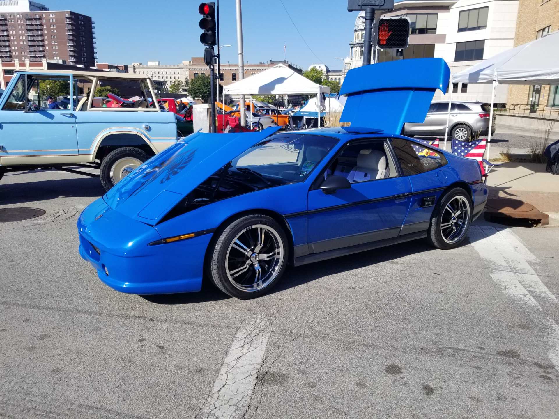
Cleaned the Fiero up some for the car show in Springfield on Saturday:
Spent a few hours detailing the stock cradle in AutoCAD. All the suspension points are within about 0.005", but some of the crossmember shapes are appoximates. This crossmember I modified to remove the bump stop pad and trimmed the area around the spring perch. The main reason for this is to document the stock suspension setup for comparison to the new setup once I design it.
I have to be out of town Monday night to Tuesday night and have some orders to process, so it will be a few more days until I can get back to this.
Slowly working on making more fixturing items for the front suspension:
With the precise fixturing table, variations in fabrication of the stock front cradle are starting to be obvious. There is 1/4" difference front the wheel flange face to the frame rails side to side. The picture above is the Driverside placement, the one below is the passenger side with the fixture in the same relative location. I need to do more measuring to understand where the difference is coming from and if it is designed in or just sloppy GM fabrication.
I have a front member that I plan on modifying and I can see that it is also either bent or poorly fabricated. I don't even have a surface plate to measure it on. This one is noticeable with a measuring tape. I don't remember exactly what part of it is off though, it was several years ago that I last measured it for a C4 rack.
I need to take the front wheels off the Fiero for some new tires. While I have it up in the air, I will likely remove the two rear bolts for the front crossmember and see where the chassis side holes are.
From some preliminary measurements, the wheel flange face to the lower a-arm cross bolts were off slightly, but close. I think the a-arm to crossmember brackets are longer on the PS than on the DS.
It it wasn't "designed in", then the bolt on the chasiss would be off to the side of the hole.The rear holes are large enough for M14 bolts, but that is much too larger for some stamped steel brackets. They are likely M12 to M8 which would give them some sloppiness to accomodate this issue.
The real question is can I fix this as I design my new crossmember. At a minimum, I could add a slot to the passenger side that would allow the current hole as well as the hole that matches the drivers side.