.... and it came out about 0.0013 off between the two 45" diagonal measurements w/o any shims. Looks like my time with the machinist level, the jack bolts and hold down brackets paid off. After the concrete pour I will be able to shim it to get even closer.
Some emphasis added by me in the quote. If you get that any closer to 0, NASA will be able to contract out small jobs to you! lol
I think you are already exceeding most tolerances for standard machining work? The few times I've been involved with white papers and contracts on machining (which, has been only 3 times that I can think of, so limited experience), the tolerances were listed as 0.002.
Originally posted by Trinten: Some emphasis added by me in the quote. If you get that any closer to 0, NASA will be able to contract out small jobs to you! lol
I think you are already exceeding most tolerances for standard machining work? The few times I've been involved with white papers and contracts on machining (which, has been only 3 times that I can think of, so limited experience), the tolerances were listed as 0.002.
As always man, impressive stuff.
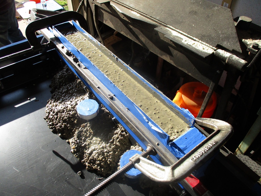
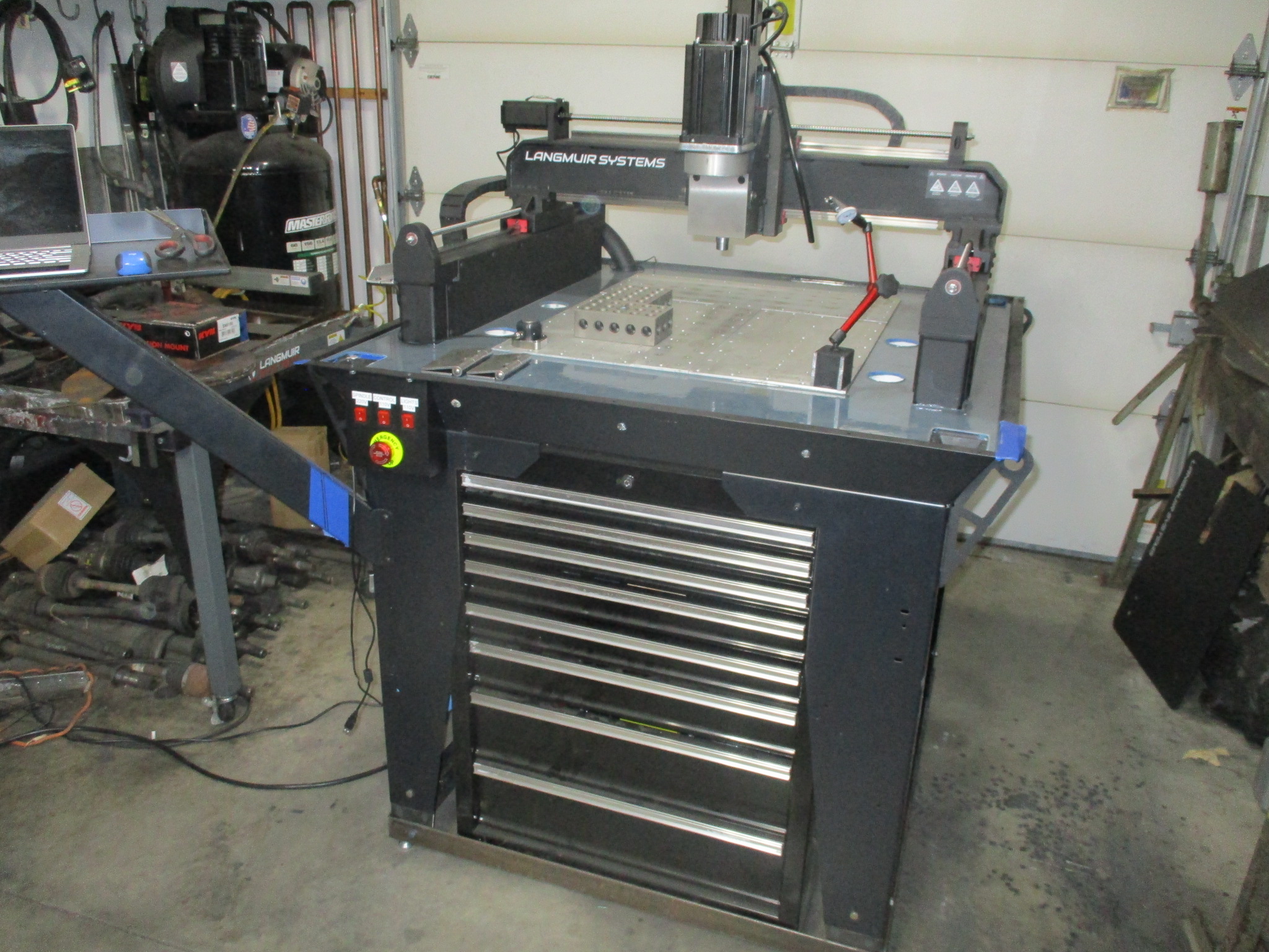
Thanks! Langmuir suggests the for the rails to be within 0.010" before pouring the concrete and then once cured shim to less than 0.005". I am not a fan of lots of shims, so I wanted to get it as close as possible before concrete. Just like my Fiero swaps, I am putting my own spin on the assembly to make it my own.
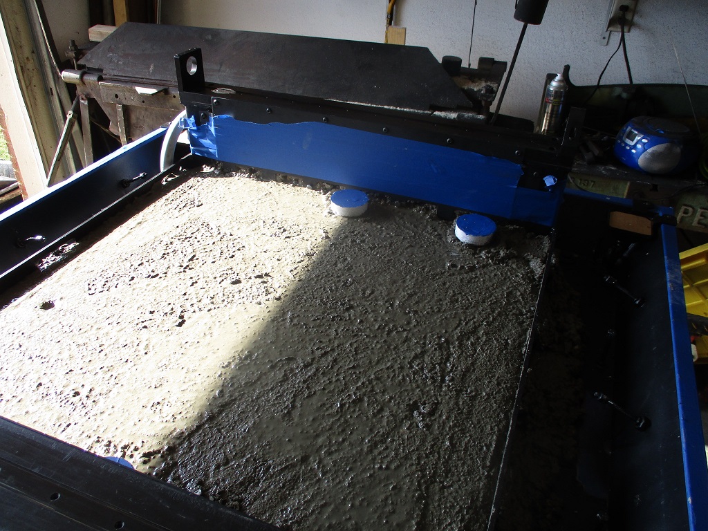
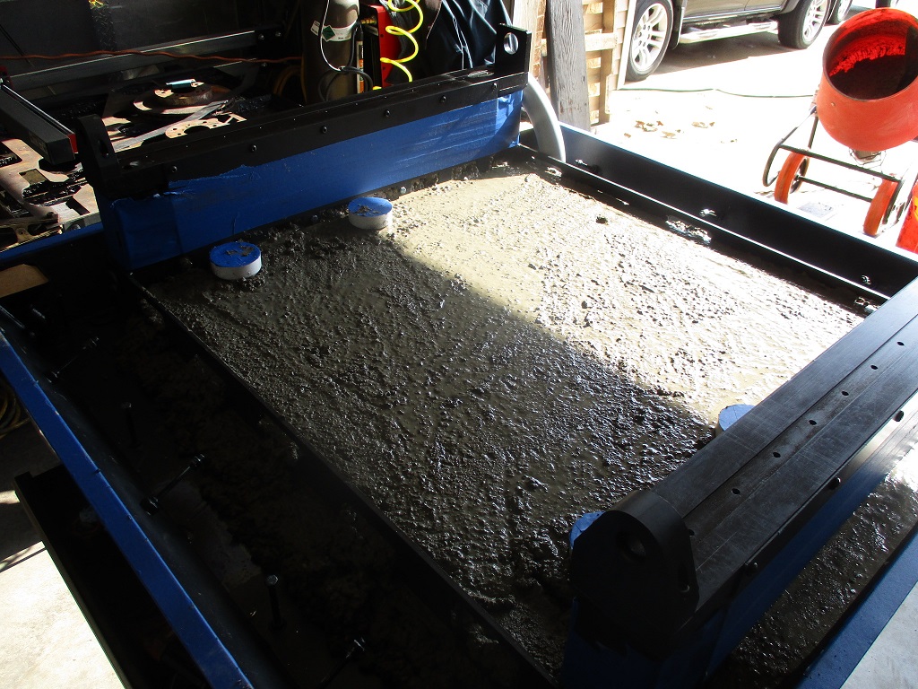
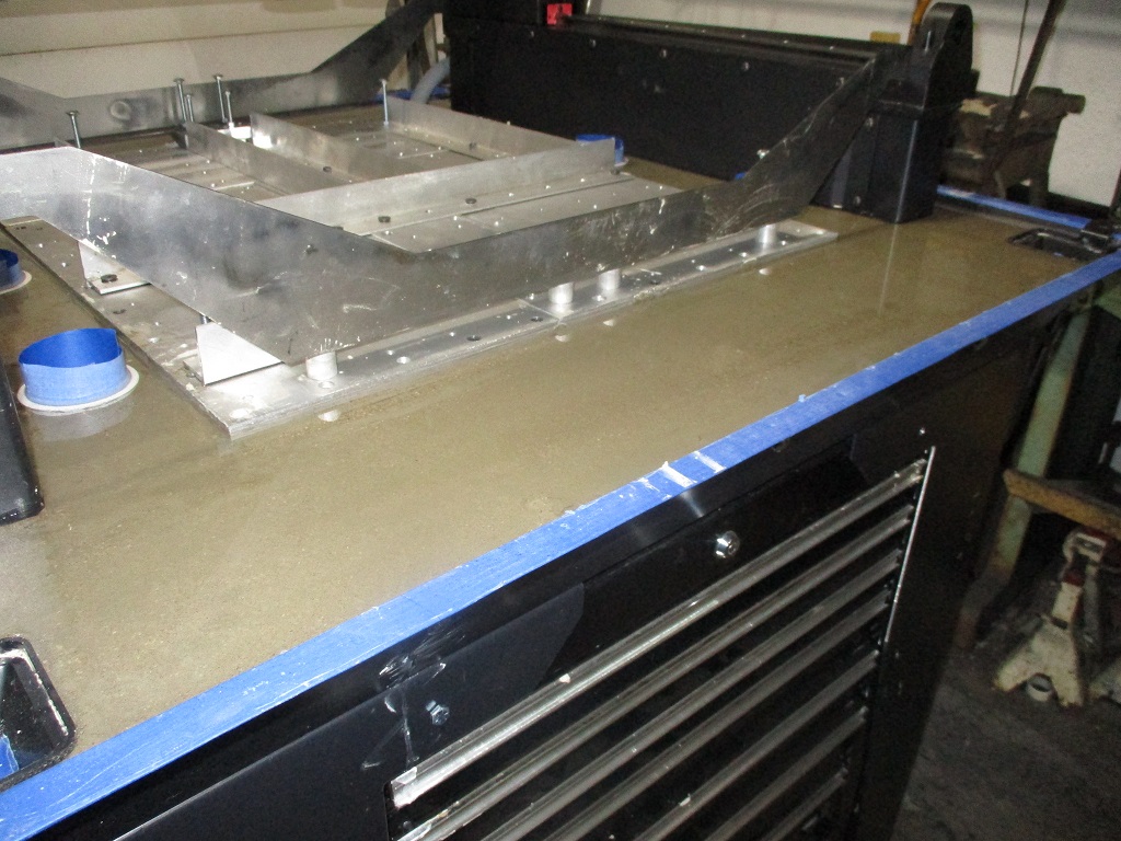
Concrete is done! Used 80 lb bags and mixed 2 at a time in a rental mixer. Used a 5 gallon bucket to transfer the concrete to the tray. My modified concrete pour sequence worked like a charm and the baseplate went in without much fuss.
Filling the Y-rail cavities (this is a modification unique to my install):
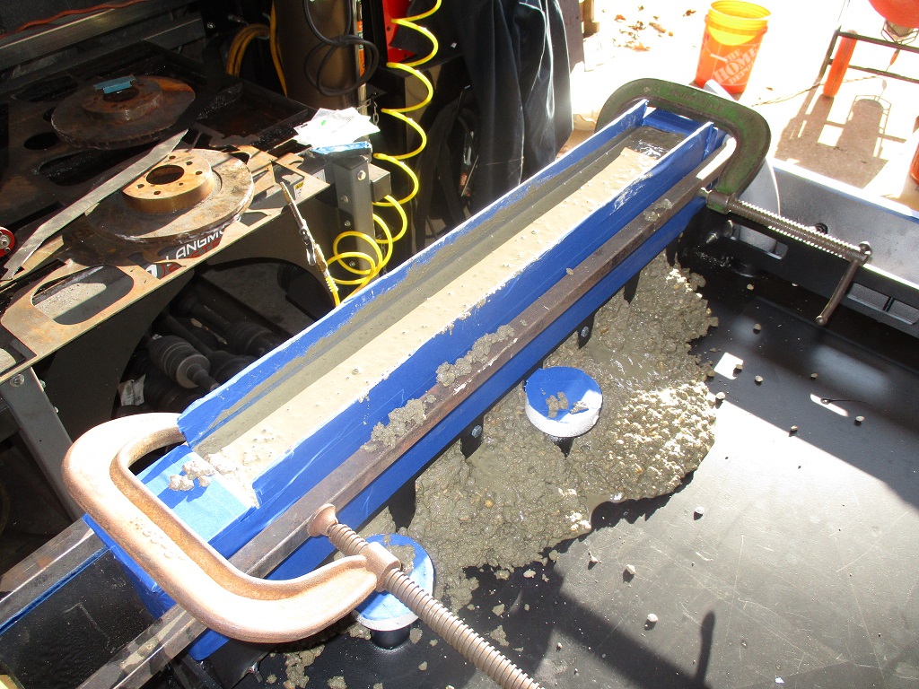
Removed the tape, installed the top rails, and bolted the side plates to the top rail. Then squared the assembly and tightened all the bolts.
Then started filling just the center section of the pan:
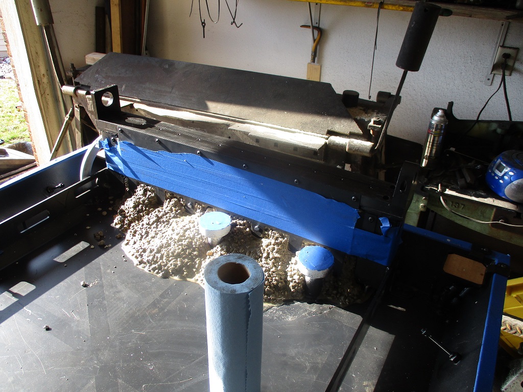
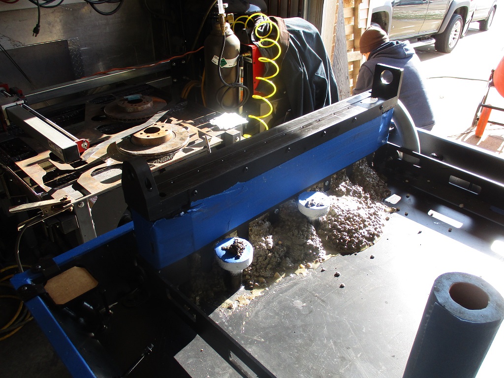
Added another couple of buckets of concrete and installed the base plate and positioned it tight to the right side of the left rail. Then filled in the outer perimeter of the pan, leveled everything off and started to remove all the tape and wipe things down. Once everything was clean, then the linear Y-rails and the X-bridge were installed so I could make the Y-rails parallel.
I am going to let everything cure until the morning and then I will add more water for a pond cure for at least 14 days.
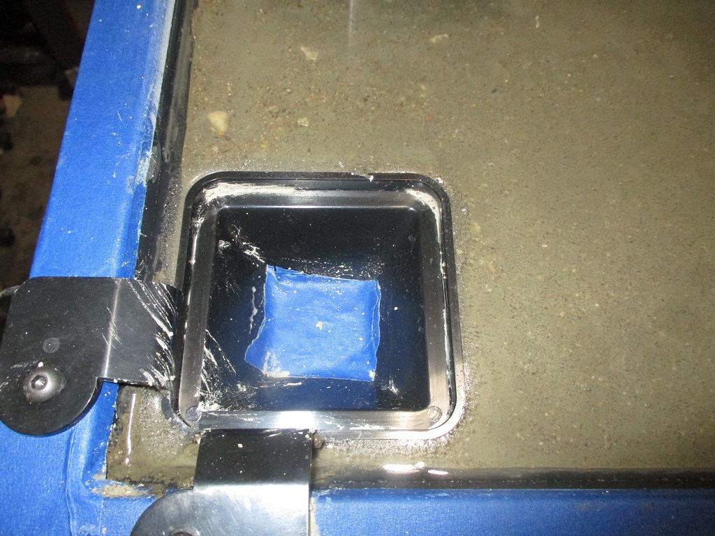
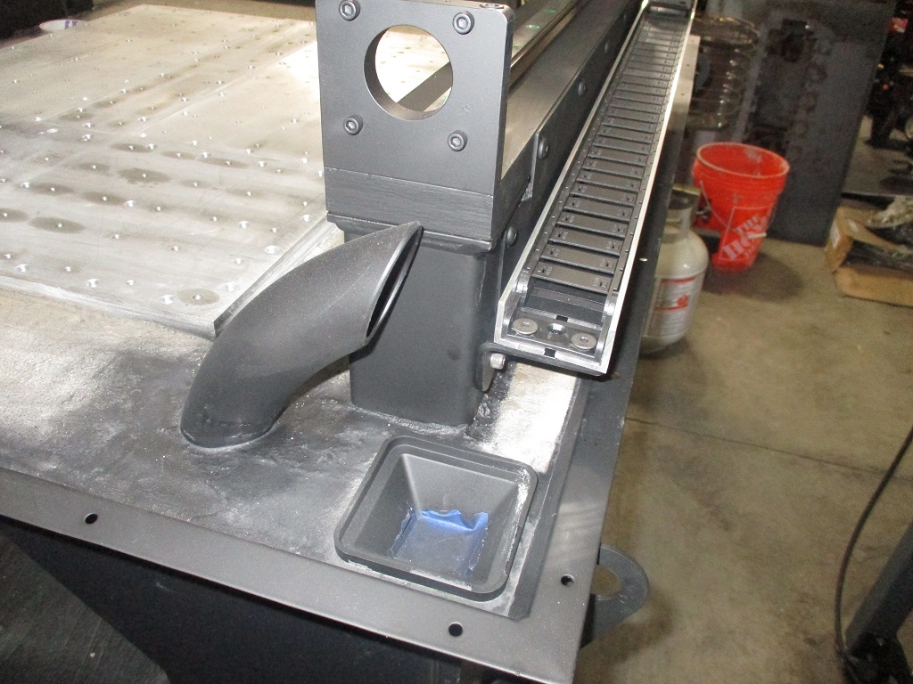
Started the pond cure this morning. Took about 1.25 gallons, so I will need to get a little more epoxy while I wait. 3 of the 4 corner drains are almost perfectly flat and level with each other, The one in the left rear seems to have popped up about 1/16". I think I will trim the sides of this one down prior to the epoxy. The new center drains are about 1/8" lower than the corner ones, so I will use tape like shown to create an edge dam for the epoxy on all the drains.
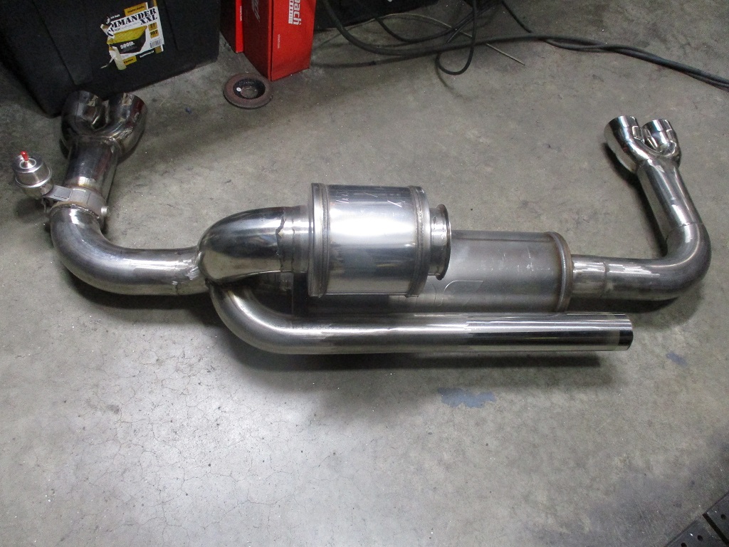
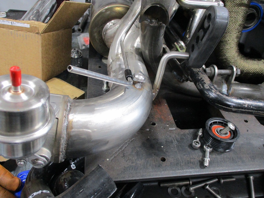
Now that I am in a holding pattern for the mill, I started to do some more work on the Fiero. Today I completed all the finish welding on the cold side and the exhaust. I also swapped out the vacuum activated cutout with one that is boost activated.
I spent the last week on vacation out in AZ and spent a couple of days in Phoenix, Sedona, and the Grand Canyon.
The concrete base for the mill is still pond curing the concrete (14 days in), but I was able to start removing the support brackets between the baseplate and removed the brackets from the corner drains - they just snap off. I will give it another couple of days and drain it. This coming weekend I plan to do the do the epoxy coat.
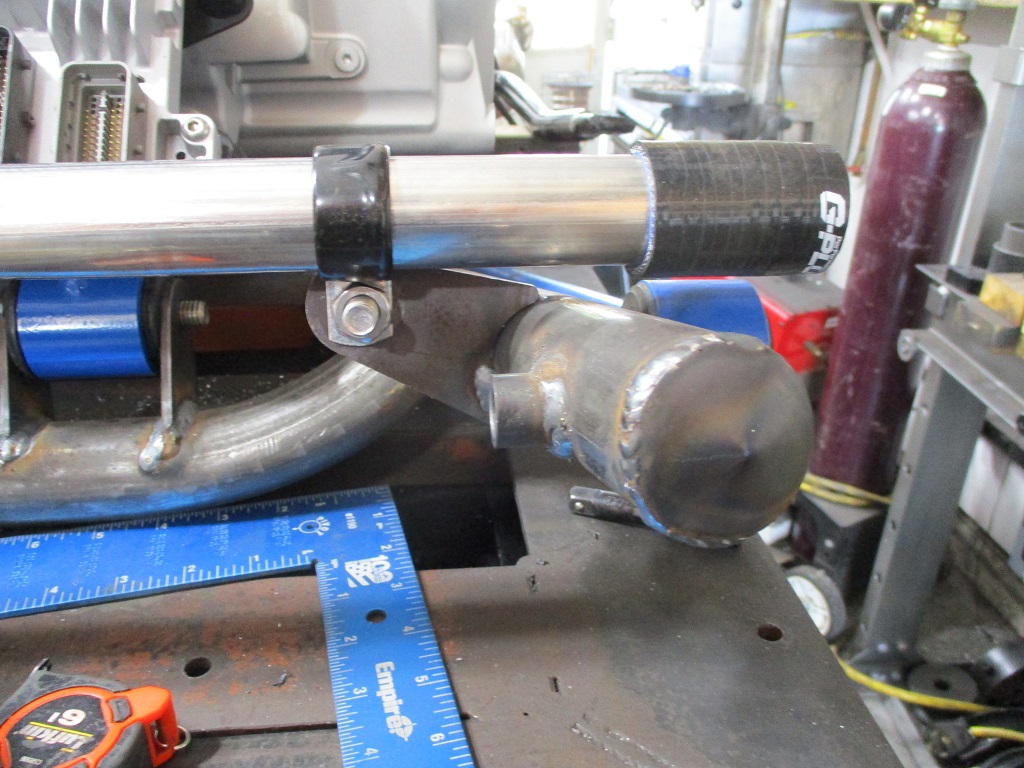
I was also able to finish up the resonator tube for the exhaust.
[This message has been edited by fieroguru (edited 03-19-2023).]
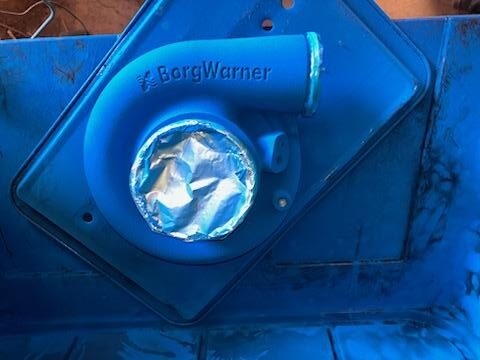
The mass airflow meter is on the wrong side of the turbo. It needs to be on the intake side after the filter before the turbo and it also needs to be in a smaller tube about 3" so it can read the actual flow of incoming air, Not pressure! I don't think you will be able to get it to even start where you have it and if it did the boost would break it and send shrapnel directly into the intake.
The mass airflow meter is on the wrong side of the turbo. It needs to be on the intake side after the filter before the turbo and it also needs to be in a smaller tube about 3" so it can read the actual flow of incoming air, Not pressure! I don't think you will be able to get it to even start where you have it and if it did the boost would break it and send shrapnel directly into the intake.
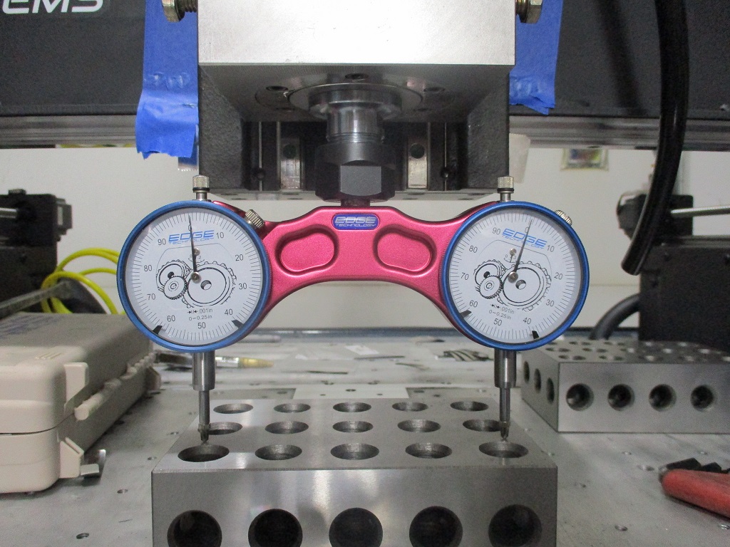
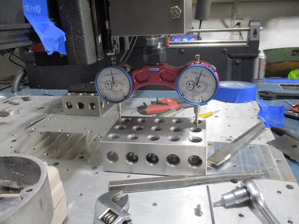
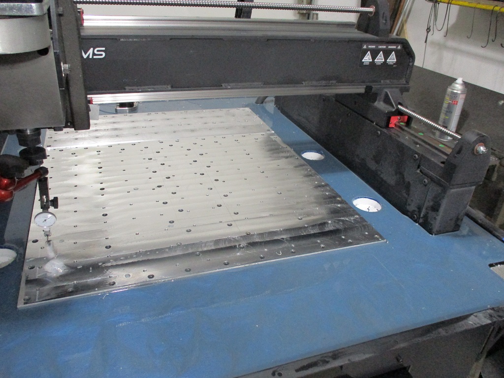
Nothing really picture worthy... Drained the water from the pond cure on the concrete for the mill base. Roughed up the surface for the epoxy coat. Checked the Y-rail co-planarity and got it within 0.001 across over 40+ in using Langmuir's tool and verified it with my machinist level. Gave the Y-rails and cable tube a fresh coat of paint.
Next weekend I should be able to pour the epoxy top coat.
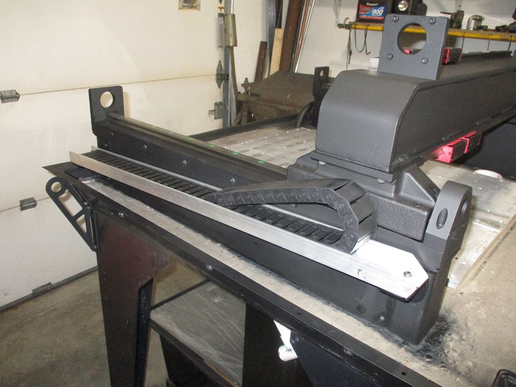
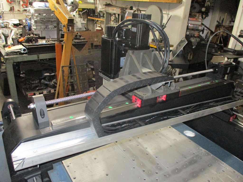
Today I did some more touch up painting and installed a flexible cable tray for the Y-axis. There will be another one similar to this for the cables running down the X/Z axes.
The epoxy is done. I wanted a brighter blue, but the flakes I had kept the epoxy clear, which I didn't like. So I added in the grey tint from Langmuir and it made it more a slate grey. I am just glad to be done with that step so I can continue on with the assembly.
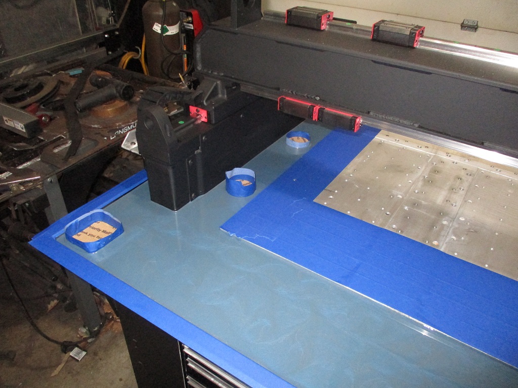
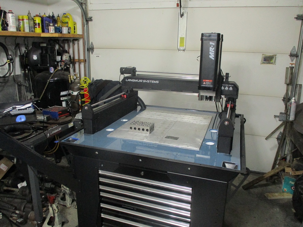
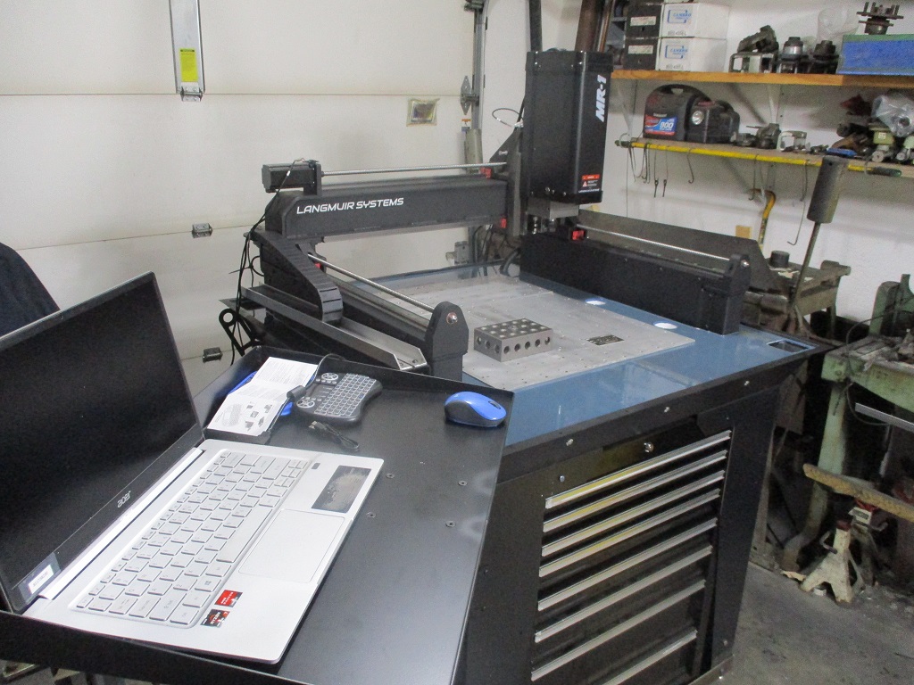
The mill continues to take shape. It was under power today and I was jogging it around squaring up the X-axis, setting limit switches, and having it complete the homing cycle.
Still have several more modifications to complete before I start installing the enclosure.
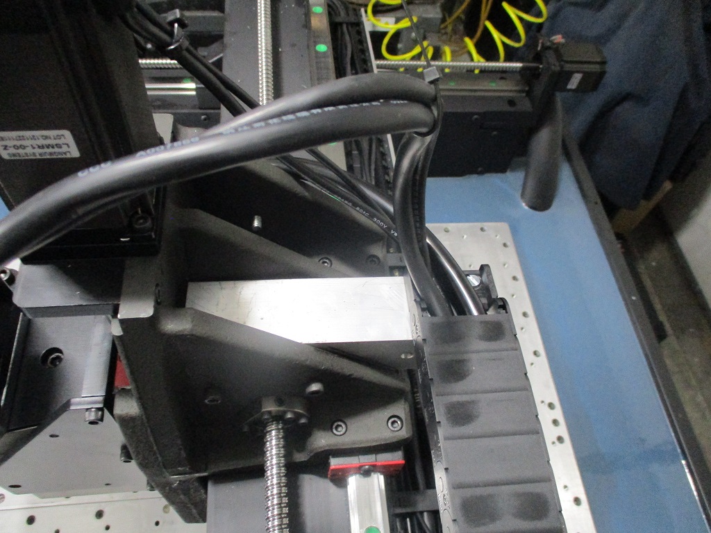
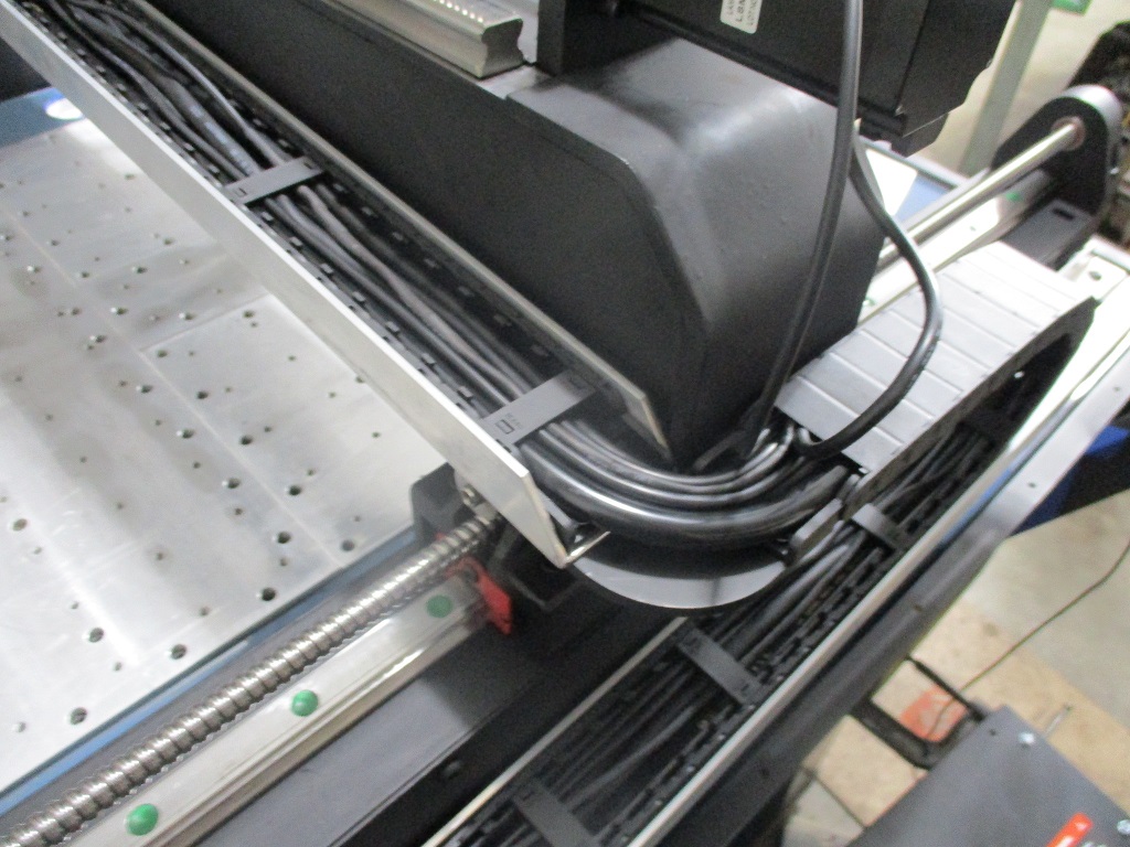
Finished with the fabrication of the cable control rails. I did end up extending the Z limit switch cable about 4’, but once that was done, everything else fits like it should. There is ample cable length to tuck the controller box up under the left hand side. All the cables are currently in place, but I left most of the covers off for fine tuning lengths at each motor/switch/device.
Here you can see the probe and flood coolant hose. Both are longer than they need to be:
Here is the backside of the spindle:
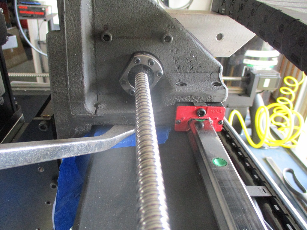
Here is the backside of the X-rail:
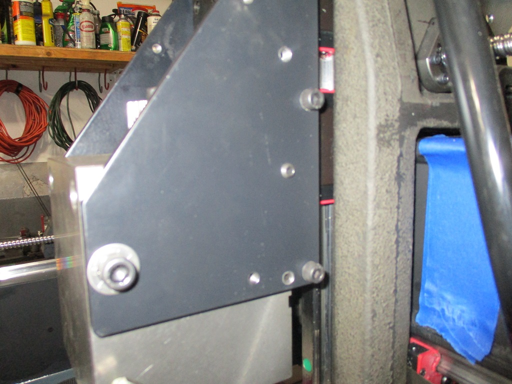
Here is the X to Y cable transition on the remade 3/16" plate:
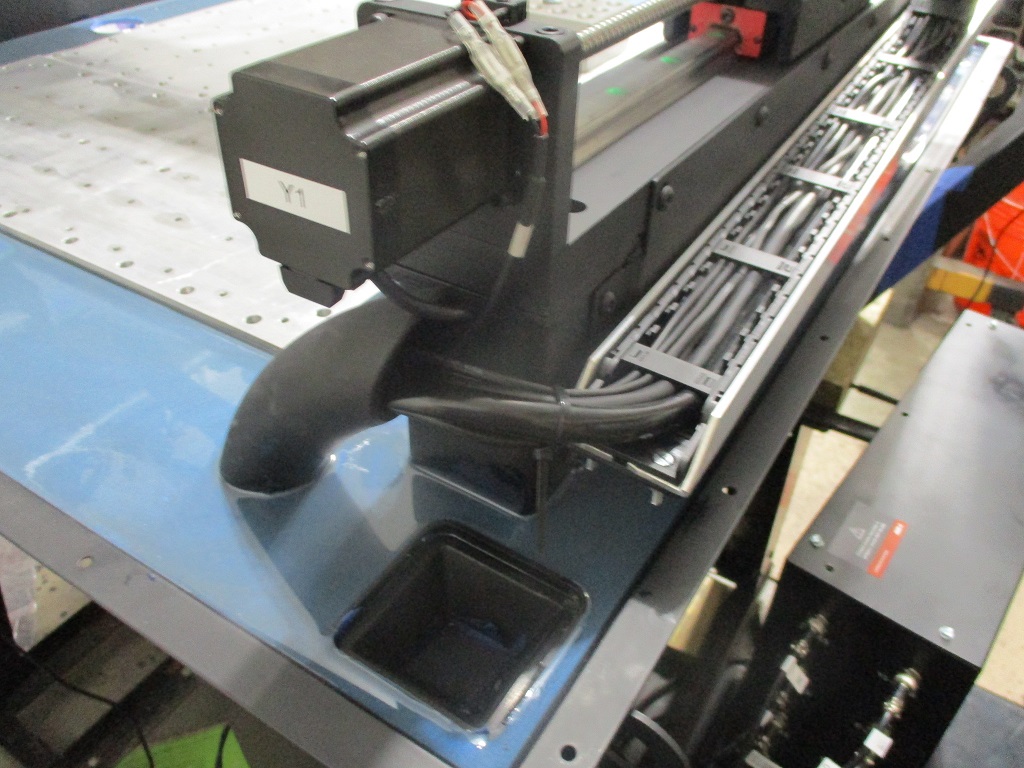
Here is the Y1 to conduit transition:
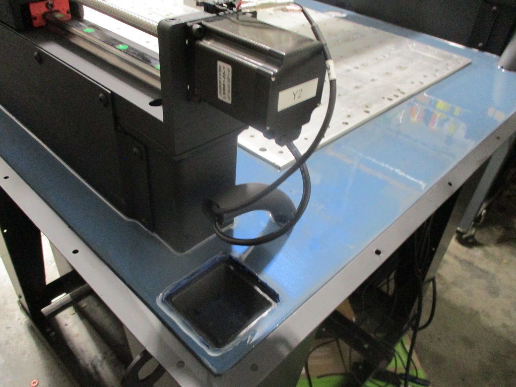
The Y2 to conduit transition:
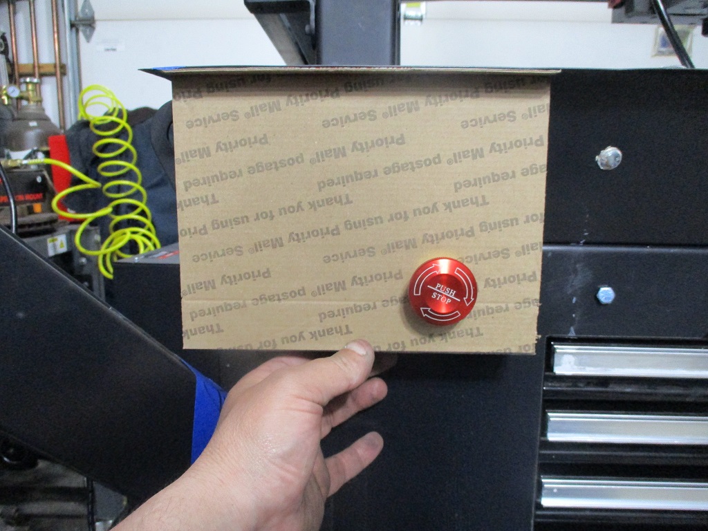
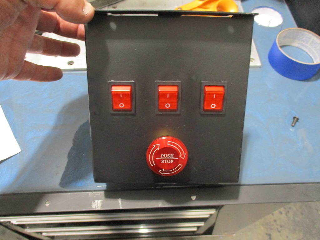
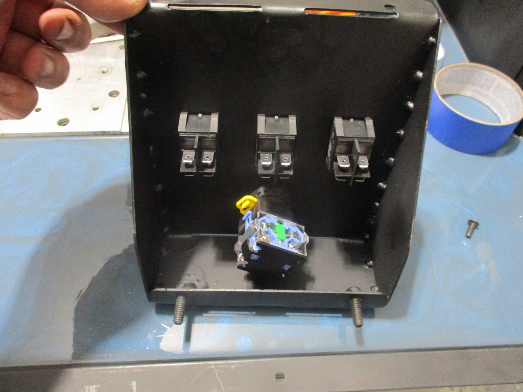
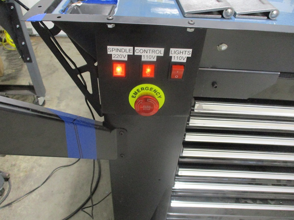
Here I am getting started with the relocate the E-stop, 120v switch and 240V switch to the front of the machine:
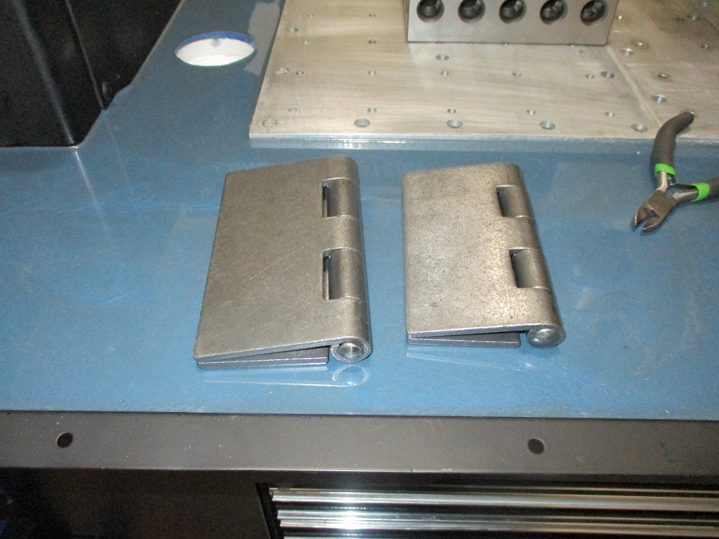
Here are the hinges for the computer stand. One to swing the arm out of the way, one to drop the laptop tray vertical.
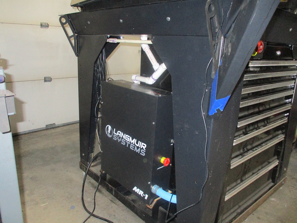
The fabrication of the auxiliary control box is done. It has the e-stop and switches for the 240V spindle, 120V control power, and 120V for the lights. The wires will pass through the leg into flexible conduit back to the control box.
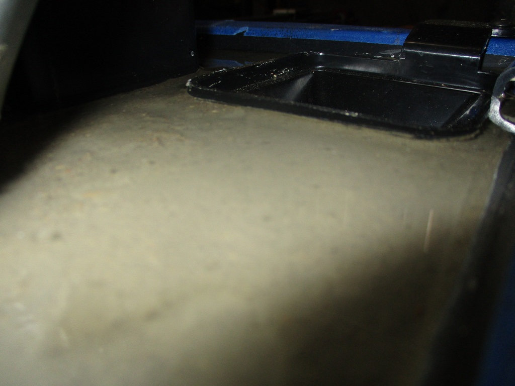
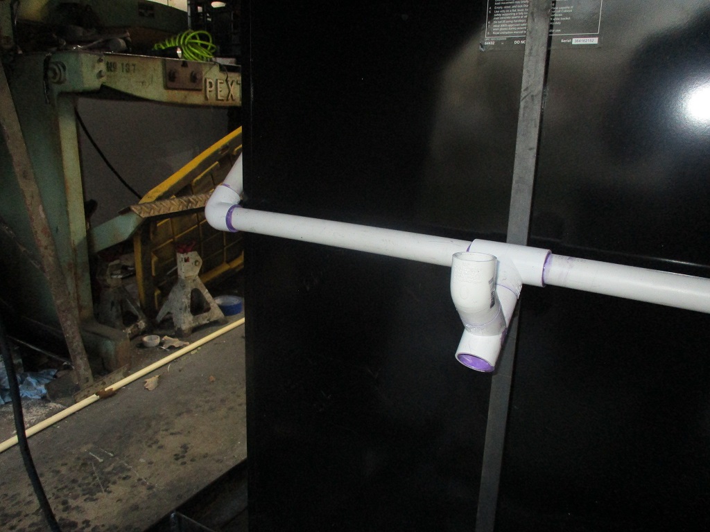
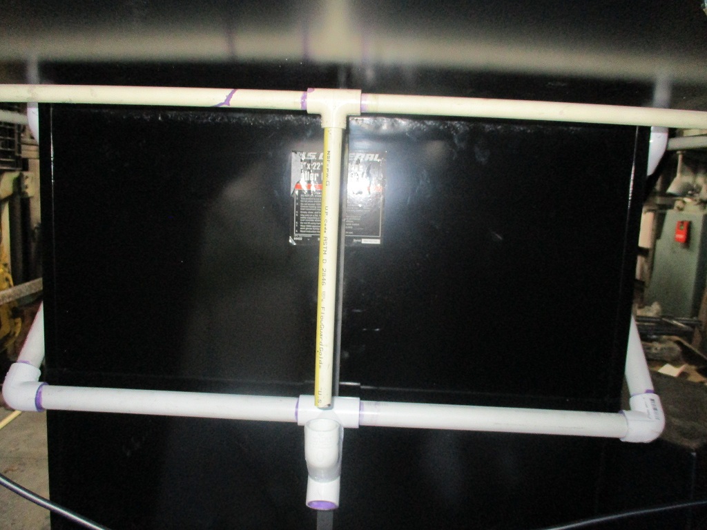
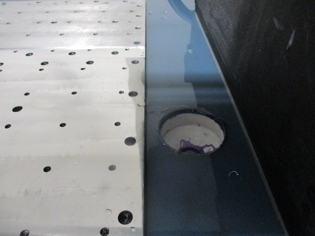
Last weekend I thought I had finished out the drain plumbing from all 8 drains to a single tube going back to the flood coolant tote.
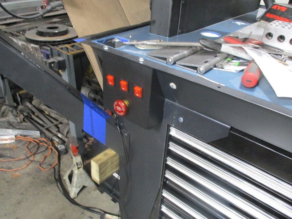
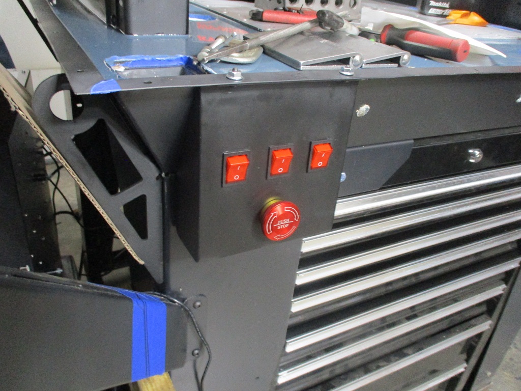
This weekend I finished up the wiring for the relocated switches and e-stop. Made a new stand to mount the control panel, which required a slight modification to the drain path on the left side, and tested everything out. Also complete the spindle break in procedure.
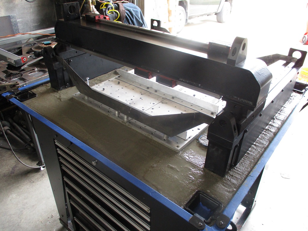
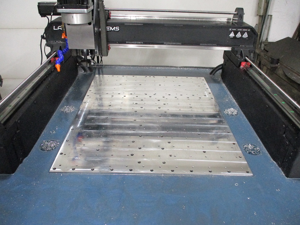
Sometime this week I will likely start surfacing the base plate so I can tram in the Z-axis.
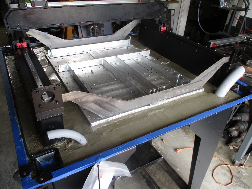
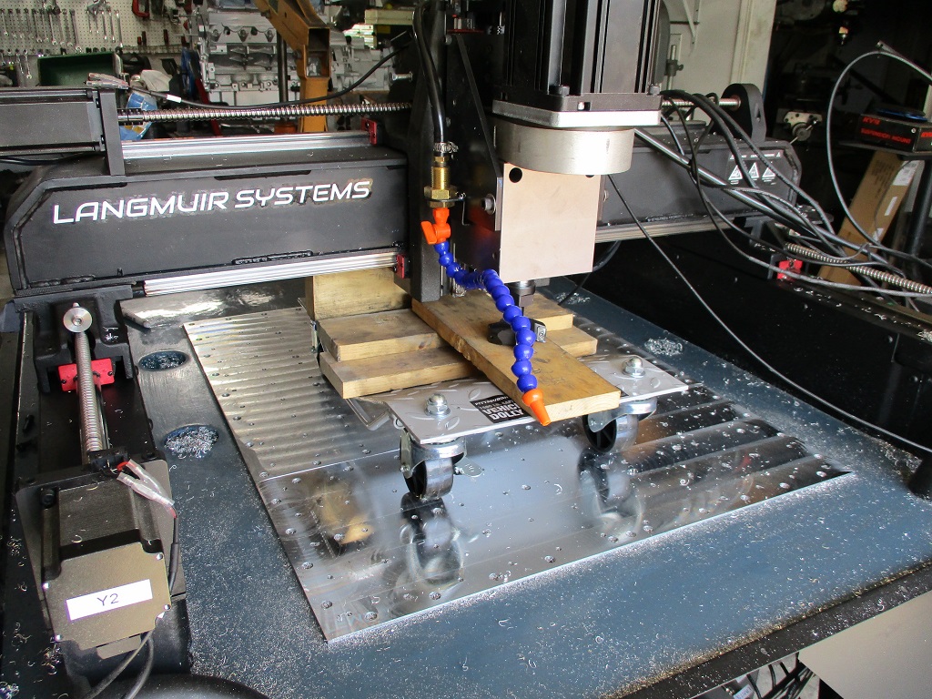
Started the first couple of passes on the thicker portions of the base plate. I use my 2.5" flycutter with the Langmuir bit holder and insert, set the rpm to 1500, feed to 15 IPM and used a 1" step over, and in manual mode.
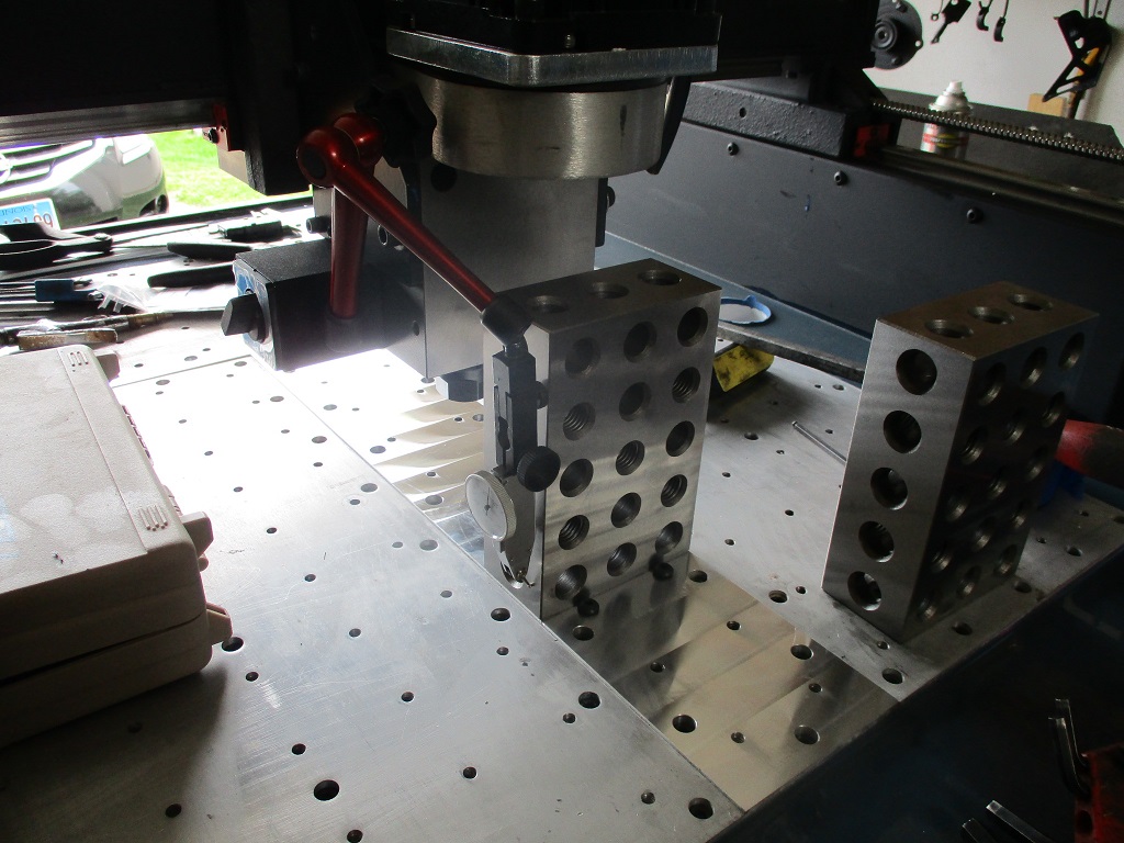
From there I stood one of my 2x4x6 blocks on end and ran the indicator down the side. This showed the Z out to the point I needed to add some shims to the top right (no shims installed during assembly).
To install the shims, I loosed the 3 large horizontal bolts on the bottom, loosened up 6 of the 8 top bolts to the bearing block - leaving the two on the far left tight, put some tape on the gantry, then used my prybar to raise the right side to slide in the shim, rerun the indicator, add/remove shims, until it was within 0.0005" across 5.5". Then I pushed the spindle carriage to the rear and tightened up the loosened bolts.
Then I turned the 2x4x6 block 90 degrees and ran the indicator up and down the front. I needed to bring the bottom out and the long horizontal bolts were already loose, so I added more tape to the gantry face, pried the bottom out to added shims to the bearing/block face. Rerun the indicator, add/remove shims to get within 0.0005" over 5.5".
Then I put the 2x4x6 block on its back and pulled out my 5" tram tool and zero’d it. I took the side plates off and drilled and tapped three 1/4-20 holes on each side. The holes are 3/4" from the back of the plate. The two bottom ones are 1/4" from the bottom of the plate and 1/4" below the top of the spindle block. The top hole is 2" from the middle hole.
With the side set screws, I was able to loosen the two 1/2" bolts on the back, the front bolts through the plate, and use the 4 set screws to jack the spindle so it was level side to side (within 0.0005" over 5") after tightening all the bolts.
Then I spun the block and tram tool 90 degrees just to check… expecting it to be good to go (machined block, on machined plate…). But it was out too. The top of the spindle block needed to come away from the back. At that point, I decided to take off the motor and offset housing so I could have better access to the back of the block to install some shims. Some trial and error, but able to tighten everything back down and get within 0.0005" over 5".
Now of course when I installed the block shims to address the front/back spindle tram, it messed up my side to side tram, so I had to go back and do that again… but it was super easy to do the 2nd time.
On Sunday I am planning to surface the remainder of the front of the baseplate and check for any variations along the X and Y axis.
I am about 90% done surfacing the front of base plate. There are still 2 low spots in the front left and rear right.
This was a worn spot in the Langmuir plate and not all of this will clean up, but anything past the 1/4-20 mounting holes will not matter anyway.
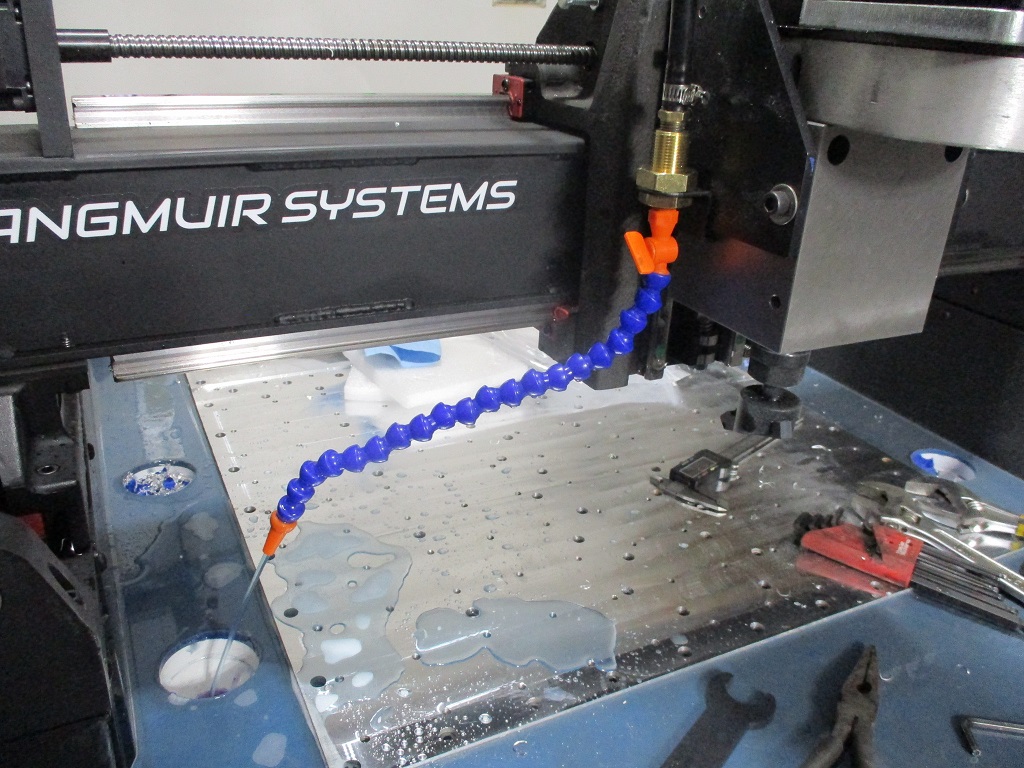
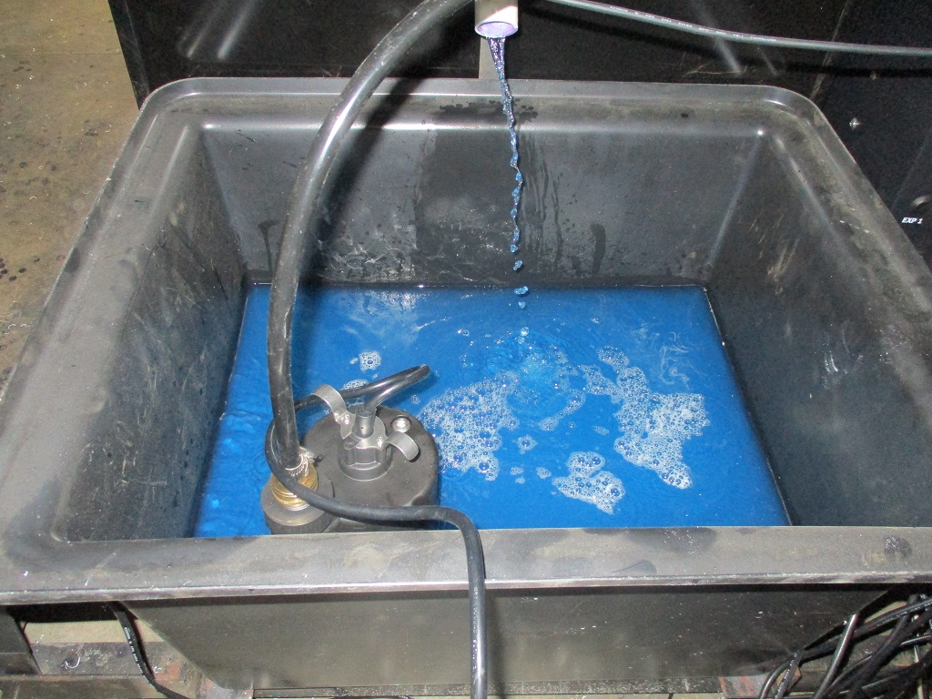
I wanted to have the flood coolant operational for the finish passes so I took some time today to get everything hooked up and mixed up about 5 gallons of the fusion coolant.
I had to reread your previous posts to understand what you were doing and why but I see it now. That is some heavy and sturdy machine!
I know now it takes a lot of steps before you have a cnc'ed part in your hands. I recently finished my hobby cnc router that never worked when I got it 15 years ago. It is a less accurate and cheaper machine but the working principle is the same. Replaced all drivers, wiring and BOB, made a nice control box and got it tuned up in Mach3. It was quite a learning curve and a lot of things to sort out. Then there is the workflow from design to gcode and the actual part. My workflow for 3D printing didn't cut it (!) for the router so I started using Freecad and already made some parts. It is incredible how much time I spend to get this far. But it is priceless to have machines that can make parts without spending hours sanding and using handtools to get a part that is maybe right. Good luck on making parts!
Yeah, my CNC plasma was a game changer for all my metal brackets and paid for itself in the first year. I can now use more creative and lighter designs and cut them out much, much faster. I am expecting the same from the CNC mill. It will open up the ability to machine many of my current parts I outsource as well as some new parts I have in development.
It has been a lot of work to assemble and modify the machine to maximize its capabilities, but it should be worth it in the long run.
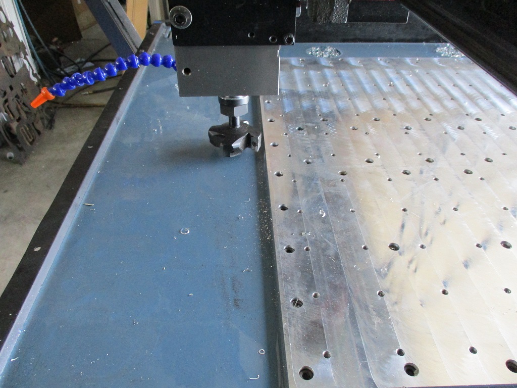
Finished surfacing the front of the baseplate and flipped the X-axis 180 degrees to the spindle is on the rear. This will allow me to surface the rear base plate.
Also spent some time sand blasting the various brackets and parts I fabricated for the swap. Still have several more parts to sandblast and then it will be time to paint or powder coat.
The baseplate is now fully surfaced and the X-axis is back in the proper orientation. Some things I learned... don't be surprised to see around .005" difference between the X-carriage and the baseplate when you flip it due to some tolerance stacking. I used some of the shims to true it up so the front and rear baseplates would be parallel with each other.
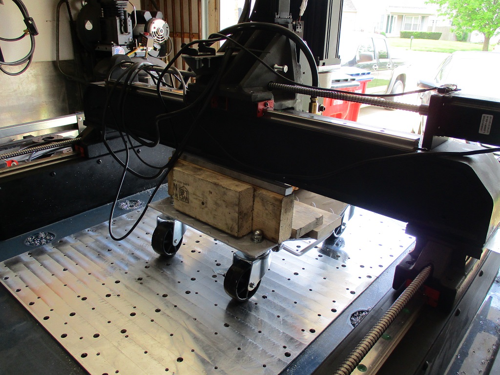
The wheel dolly worked great to flip the X-Axis around. The 3/16" spacers came in handy as I could pull them out and then the X/Z-axes would rest on the dolly and clear the Y-rail carriages
The one regret with all my mockup before concrete, I didn't install the Z-axis to verify where the spindle ended up along the Y-axis. With the flycutter, I could have easily made the baseplate 32 " and used this space at the front. I used the specified spacing from Langmuir, bit this was a missed opportunity.
For the 2 center drains, I used some thick & coarse scotchbrite to act as a filter. Just cut them in slightly oversized circles and pressed them into place.
You would probably kill it if you had a youtube channel that follows your work, I bet lots of people would be super interested. A retirement possibility?
Looking forwards to seeing chips fly, and also seeing the turbo setup fire up.
From the 3 forums I post stuff on, I get a lot of positive feedback and lots of views on my threads. I possibly could do more on Youtube, but that really isn't my thing. I would rather spend my limited free time doing what I love to do vs. cutting it in half to make, edit, and post videos. Sure it might be able to make some $$, but between my day job and LLC, I don't really need to make more. I have 19 years to go before retirement, so who even knows if Youtube or its replacement will be a thing then. My retirement plan is to have a full function machine shop in the garage that I can spend my days making parts and building things, some will be for customers but most will be for my projects, which is why I continue to expand and upgrade my garage equipment.
From the 3 forums I post stuff on, I get a lot of positive feedback and lots of views on my threads. I possibly could do more on Youtube, but that really isn't my thing. I would rather spend my limited free time doing what I love to do vs. cutting it in half to make, edit, and post videos. Sure it might be able to make some $$, but between my day job and LLC, I don't really need to make more. I have 19 years to go before retirement, so who even knows if Youtube or its replacement will be a thing then. My retirement plan is to have a full function machine shop in the garage that I can spend my days making parts and building things, some will be for customers but most will be for my projects, which is why I continue to expand and upgrade my garage equipment.
you may want to look into this, my kids tell me that those with a lot of followers, make serious $$$$ off youtube.
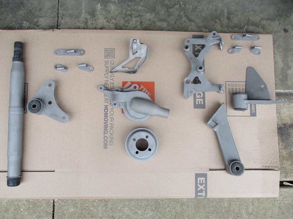
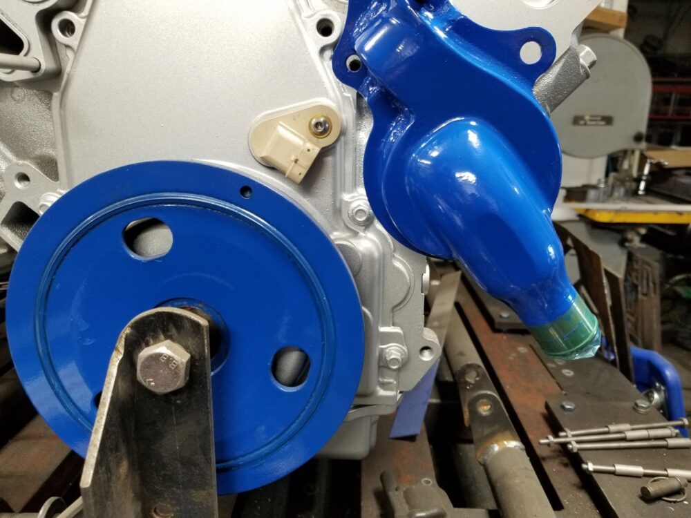
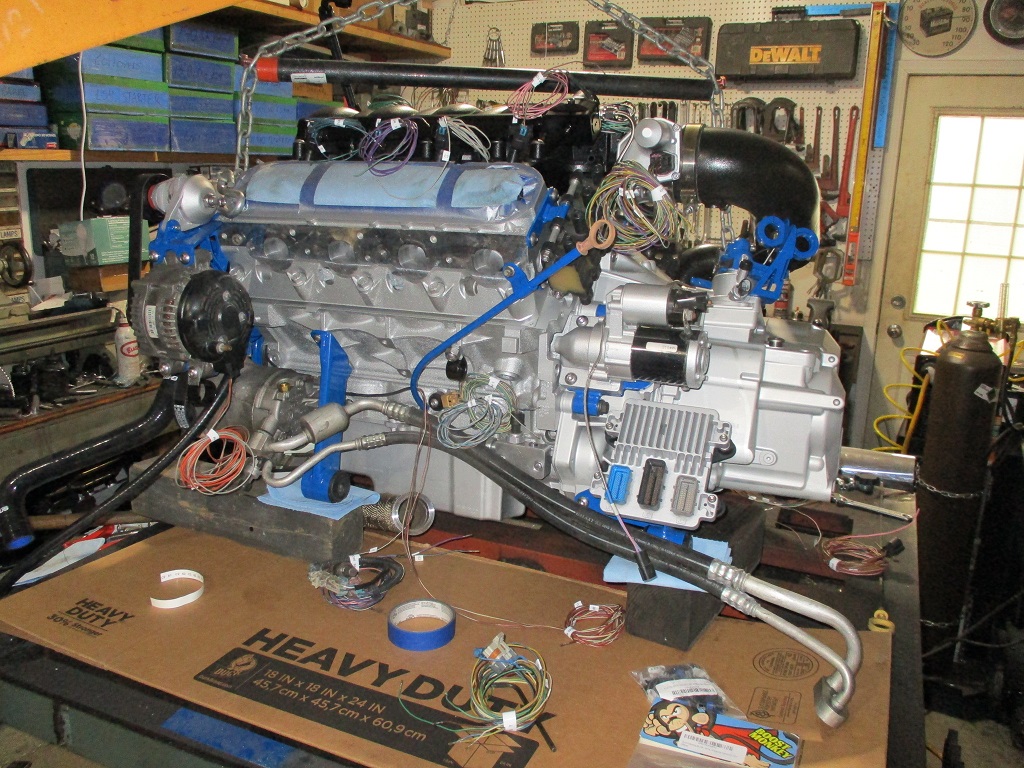
Haven't messed with the mill in the last 2 or so weeks as I have been focused on getting my engine ready to go back in the car. Lots of sand blasting to prep for powder coating. Over the holiday weekend with Marty's help we were able to get about 60-75% of the powder coating done. Here are a few sneak peeks.
Here is a comparison of the powder coat (water pump) color and the paint (harmonic balancer) I had been using:
[This message has been edited by fieroguru (edited 05-30-2023).]
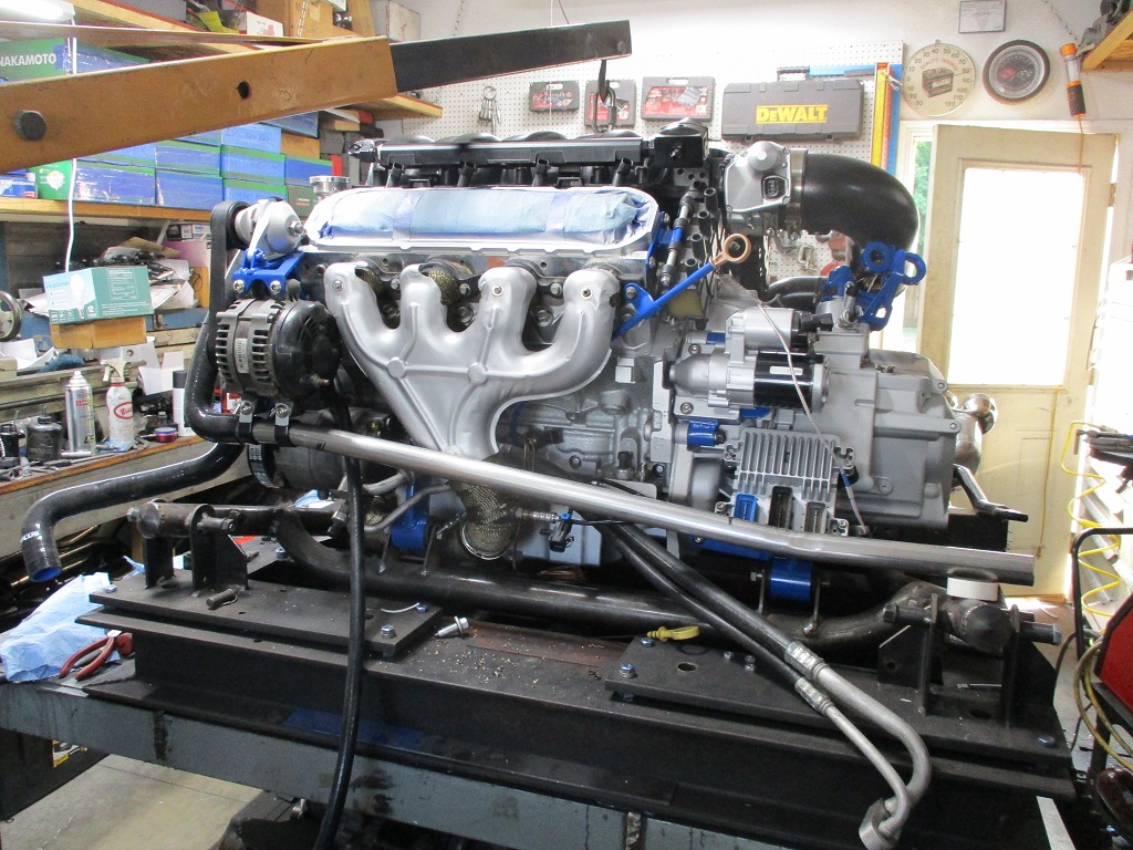
Marty and I both took Friday off so we could get the rest of the engine/transmission parts powder coated. So today I started putting things together for hopefully the last time.
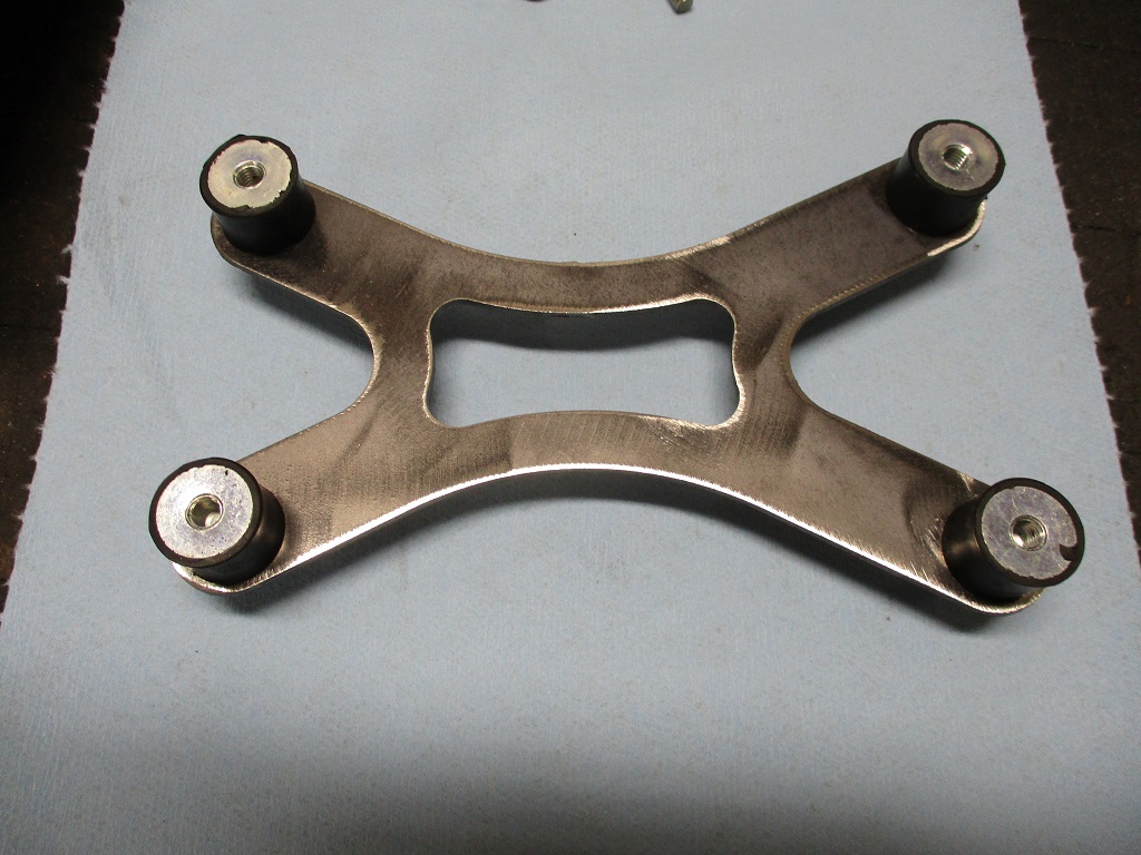
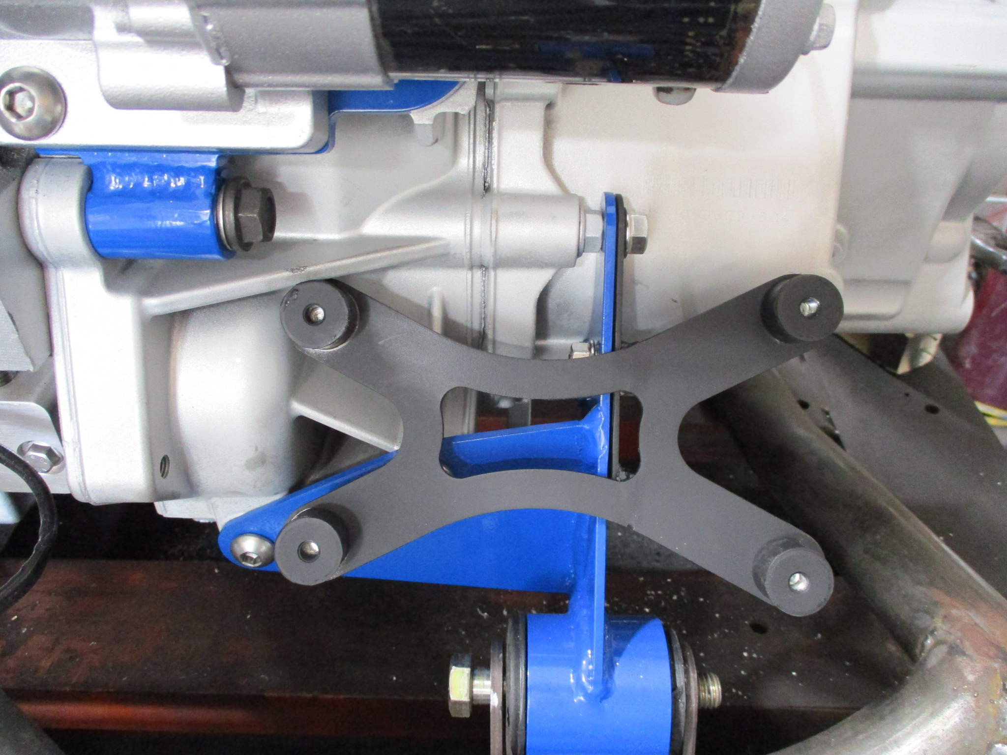
Front Transmission Mount: Clearly this was made before I got the CNC and I never bothered to rework it to add lightening openings.
LS4/F40 Starter mount - this is my new style that uses a 5/16" plate with less material in non-critical areas, so it is lighter. Side note, I have a small length of flywheel ring gear that I put in the starter pocket to lock the crankshaft for tightening and removing the balancer bolt. Today, I tightened the balancer bolt with a 3' long 3/4" breaker bar.
Front bank coil bracket - this used to have a large 1/8" plate that covered the end of the head. Everything except the bolt locations and tabs were cut away to save weight. The 1/4" all thread is also aluminum to save weight.
Modified LS4 dipstick - cut the stock bracket off, bend the dipstick to exit the rear, reshape the bracket, then weld it back together.
One of my LS4 Multi-Port Oil Bypass plates with the stock LS4 and Fiero oil pressure senders.
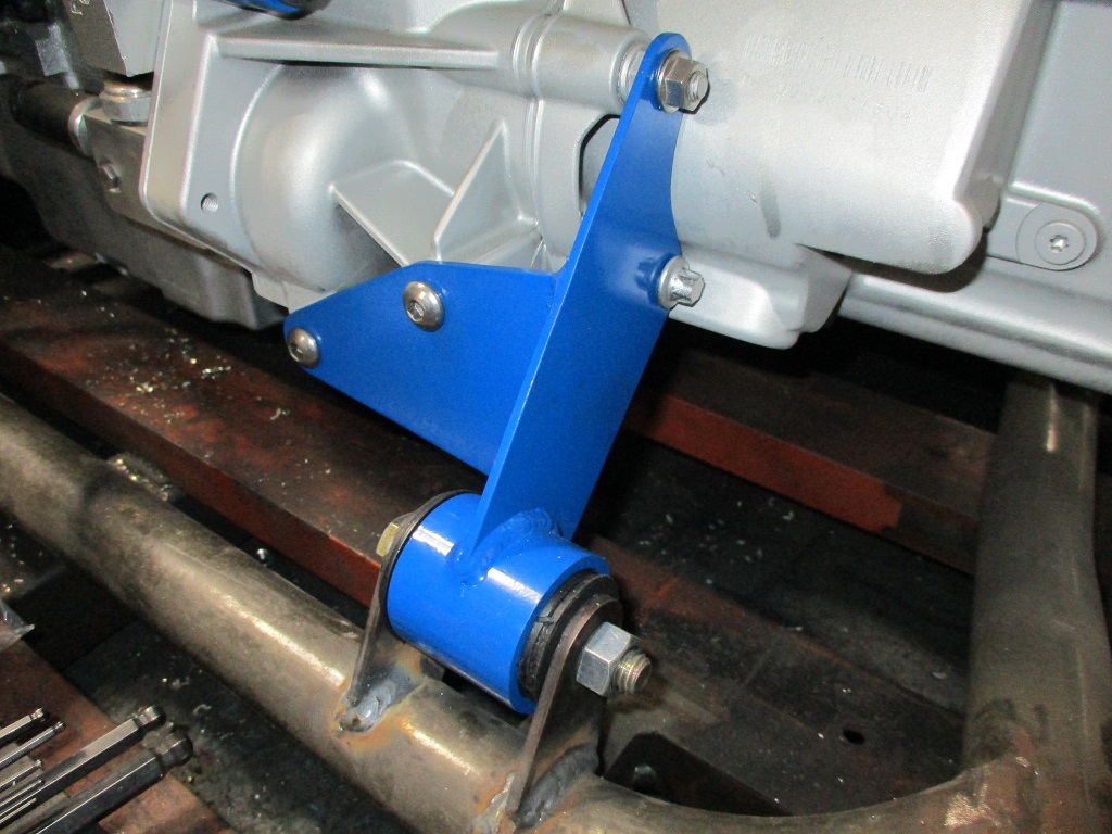
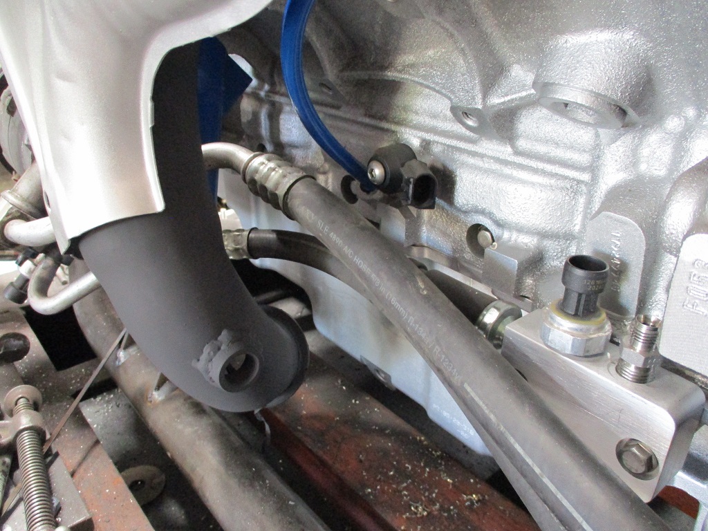
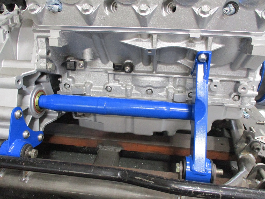
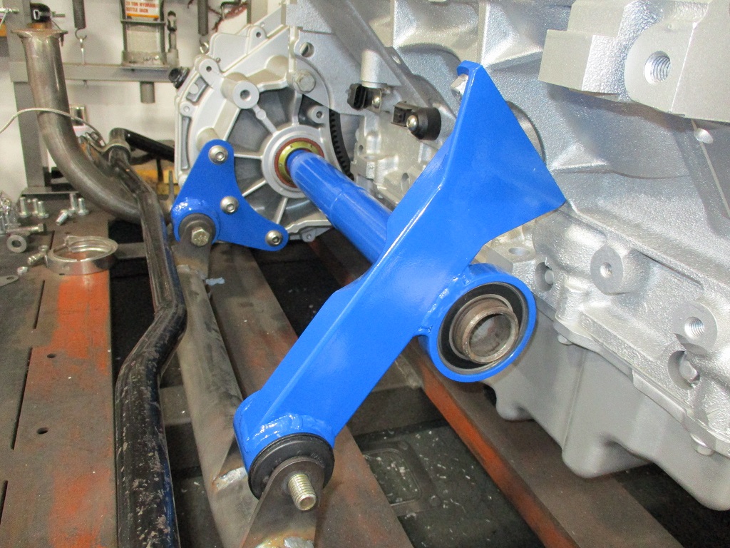
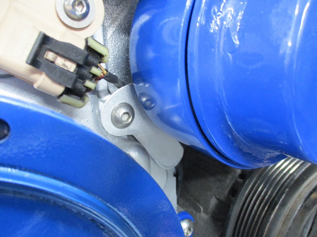
Here is the front engine mount with the integrated rear AC compressor support and the AC hose.
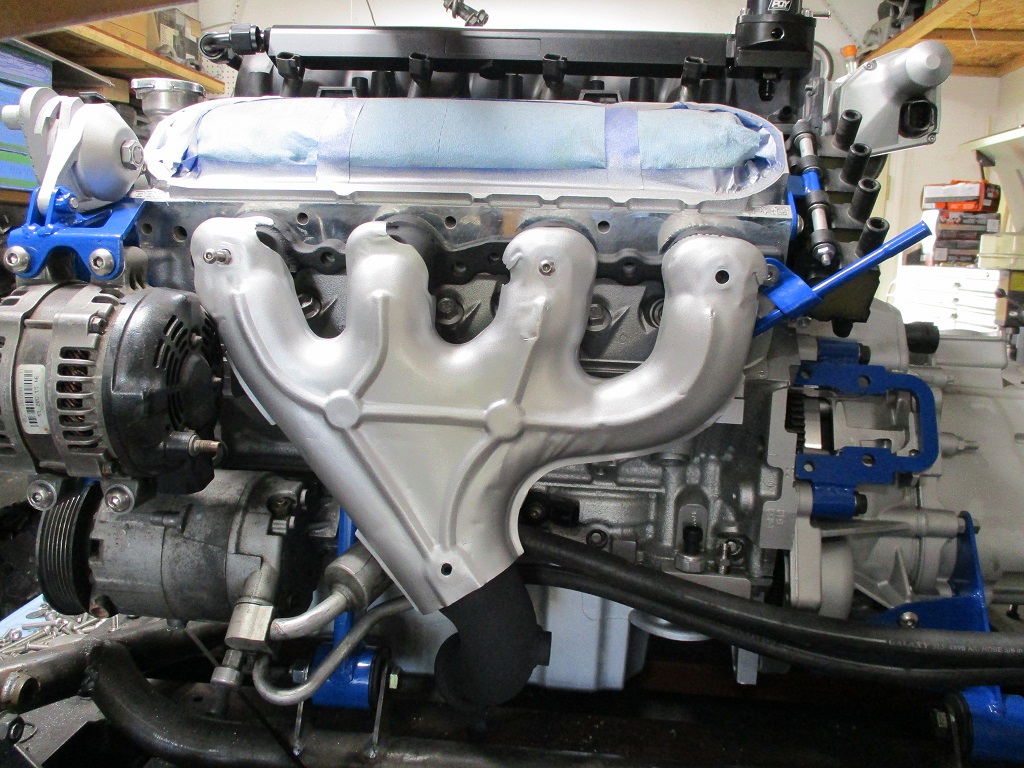
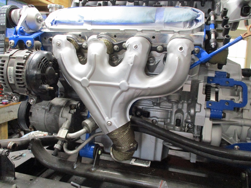
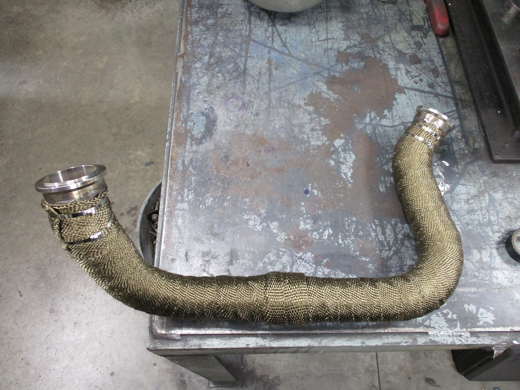
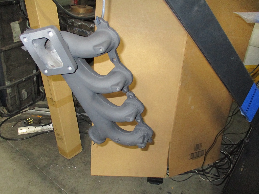
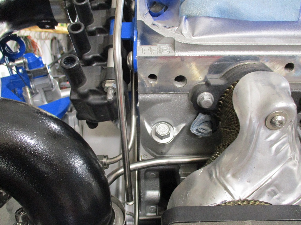
The front exhaust manifold with heat shield. This is a modified and ported LS6 exhaust manifold. I added the O2 sensor bung today, blasted it, primed and painted with some 2000 degree ceramic paint. The head shield was blasted as well and painted with aluminum engine paint. This will come off a couple more times as I will be using some exhaust wrap in a couple of locations (by the alternator and down by the AC hose).
Here is the clearance of the AC hose behind the exhaust manifold:
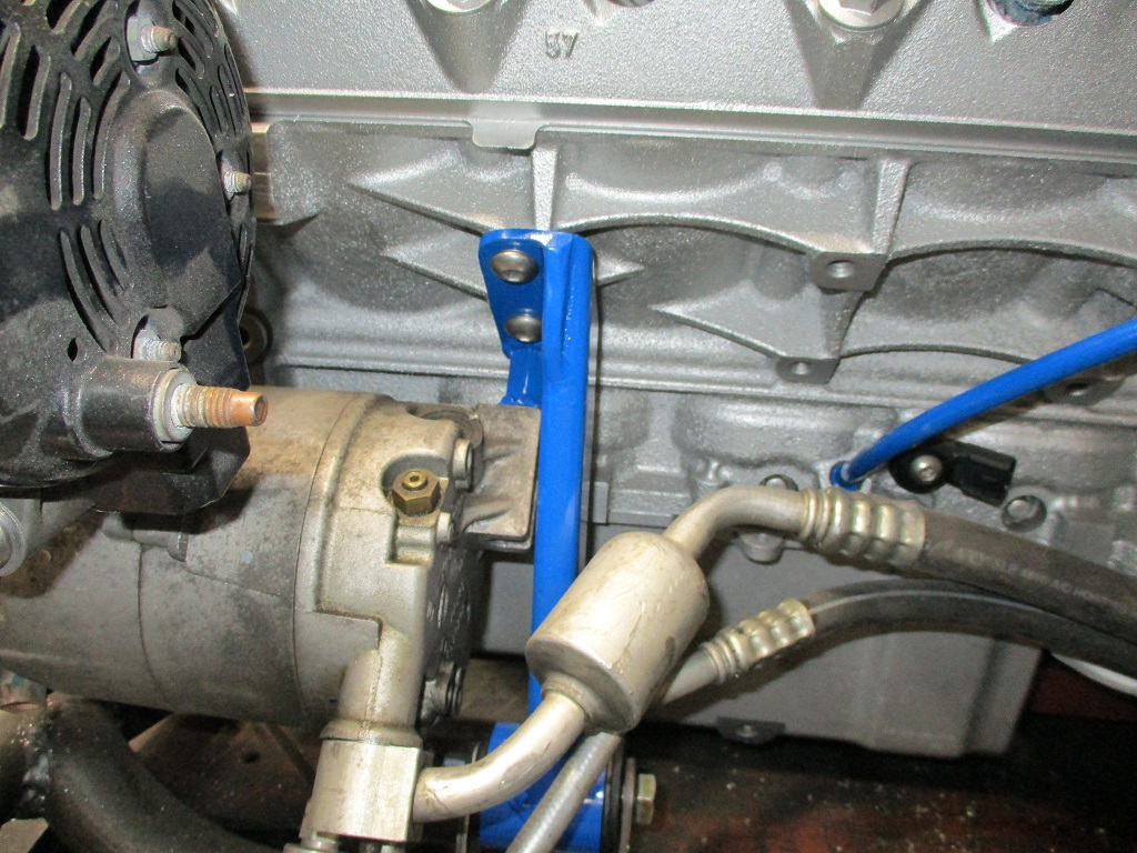
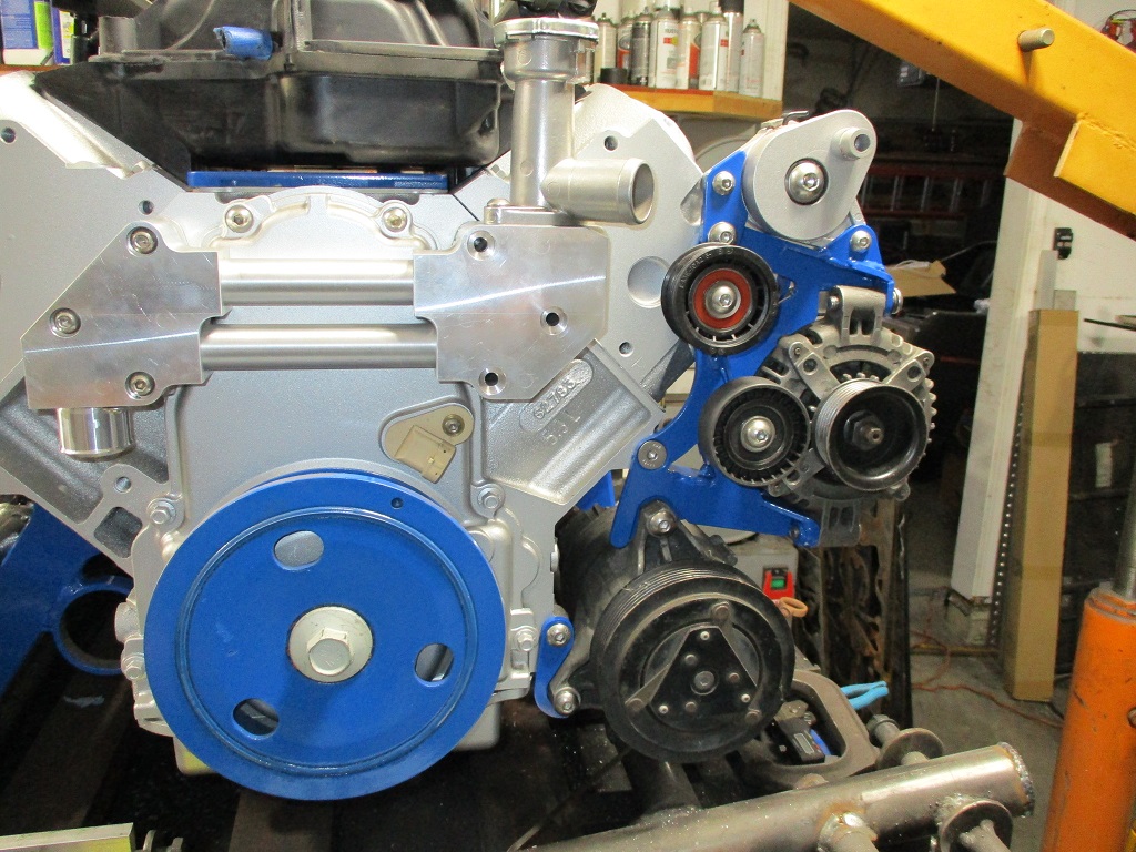
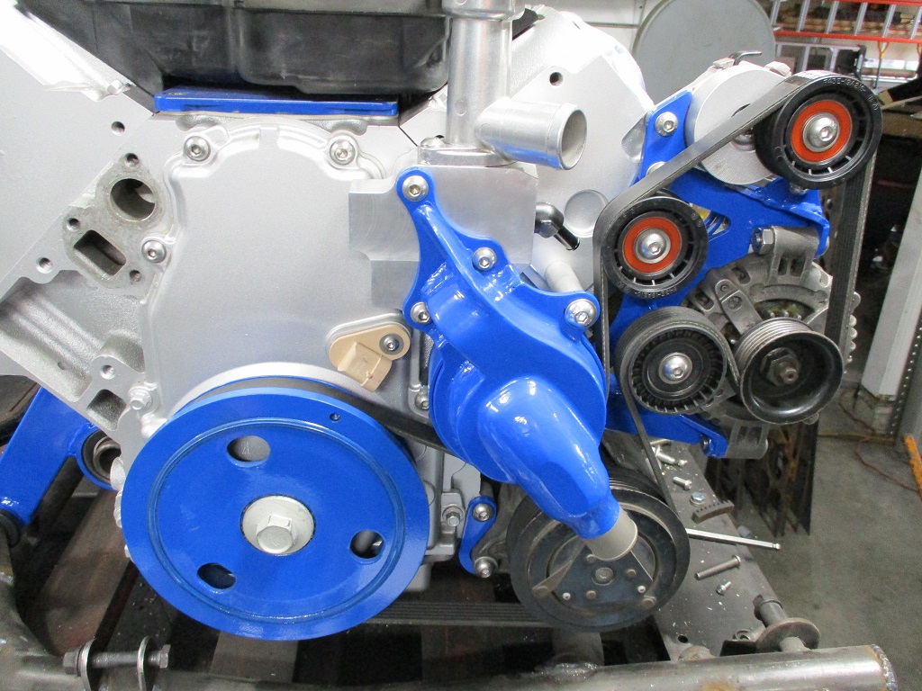
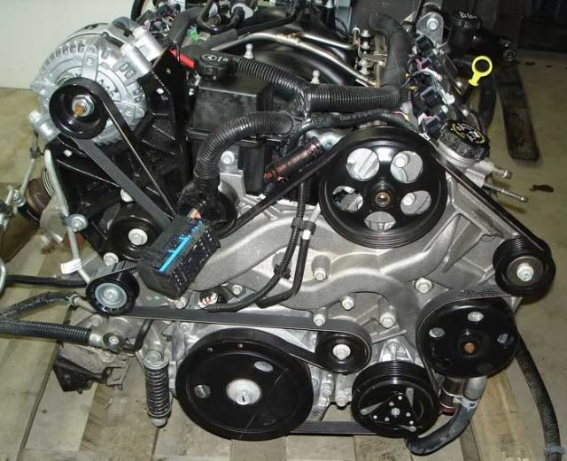
Here is the Tensioner, Alternator and AC bracket - this uses the stock LS4 alternator and LS4 AC compressor and the bracket was refined after I got the CNC plasma, so it has lots of speed holes and bracing.
The tensioner was disassembled cleaned and painted aluminum. Still waiting for all new pulleys to arrive.
Tomorrow I will continue to work my way around the engine...
Spent a fair amount of time on the water manifold today. Turned some press in plugs for the counter bored holes. Faced the plugs and front surface to make everything smooth. Milled the coolant passage from the water pump into to the coolant manifold. And turned a plug to cap replace the coolant housing input port.
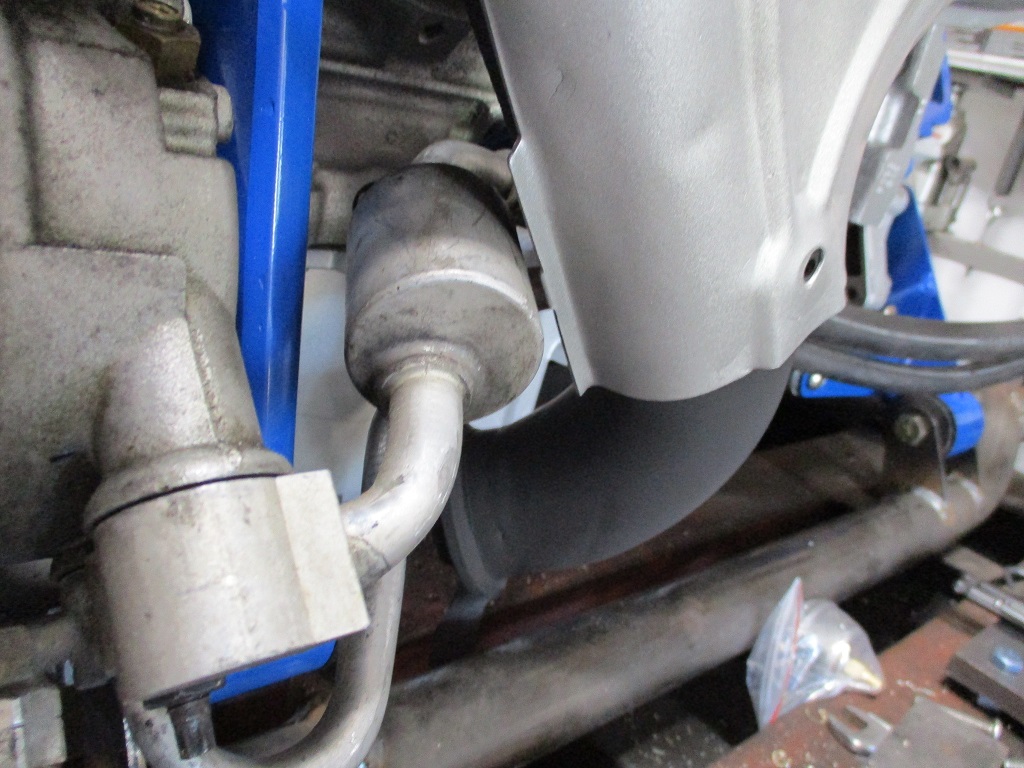
Then I did a little work on the exhaust, capped the Helmholtz tube and added in the two O2 sensor bungs.
I plan to keep knocking out tasks during the evenings this week.
I sandblasted the manifold, washed it with dawn dishwashing soap, then sand blasted again. I used the 2000 degree primer from the same brand, and followed the instructions. Time will tell if it lasts or not. I will be doing the other manifold this week.
FWIW, these manifolds were painted with VHT exhaust paint from Orielly's.
I applied it in March of 2019, following the instructions as closely as possible, and cured them in an oven. The truck has been driven tens of thousands of miles, literally across the country, it's been to Alaska, Key West, and almost everywhere in between, I also didn't have access to a sand blaster to get them really clean first, just wire brushes. all weather, rain, snow, sun, you name it. it's been on salted roads, and even spent the night at Bonneville once. it is worth mentioning though, it's a suburban with a TBI 350, Maybe if I'm lucky it makes 200 hp. your results may vary, but I'm pretty happy with mine.
Pictures of the initial installation, along with the full build are on RFT in the "other cars" section.
http://www.realfierotech.co...php?p=157628#p157628 ------------------ "I am not what you so glibly call to be a civilized man. I have broken with society for reasons which I alone am able to appreciate. I am therefore not subject to it's stupid laws, and I ask you to never allude to them in my presence again."
I invited Lou Dias to trash me in my own thread, he refused. sorry. if he trashes your thread going after me. I tried.
[This message has been edited by ericjon262 (edited 06-07-2023).]
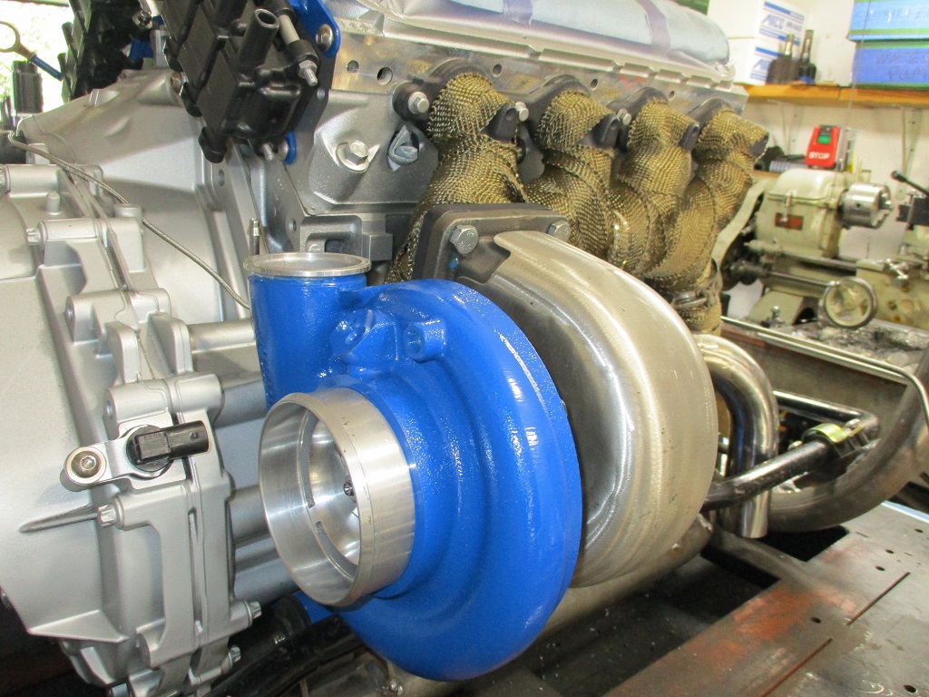
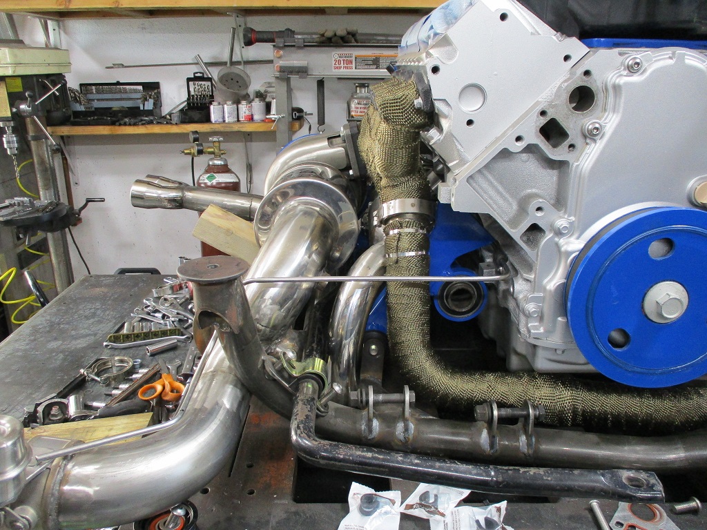
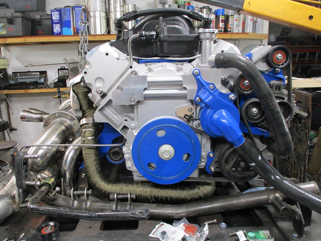
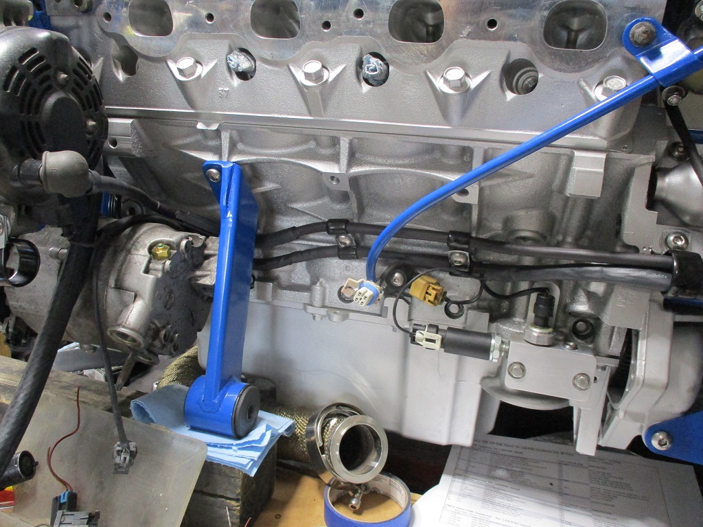
Made more progress... On the front of the engine: wrapped the front manifold under the heat shield, installed a new o-ring on the dipstick, and bolted the heat shield in place.
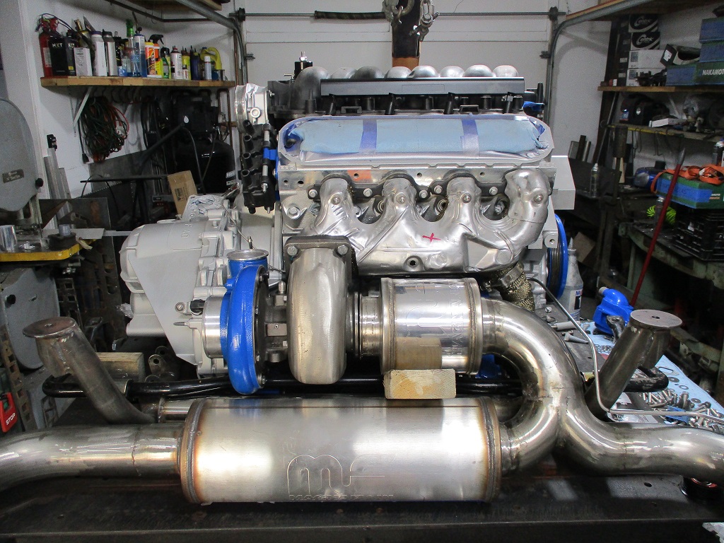
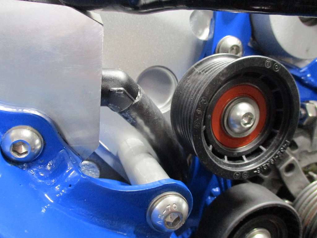
On the right side of the engine: installed new grooved idlers, heater hose nipple, made water pump support spacer and installed the bolt, swapped out the cam sensor for the 24x version, installed the thermostat, and installed the belt, and wrapped the crossover pipe.
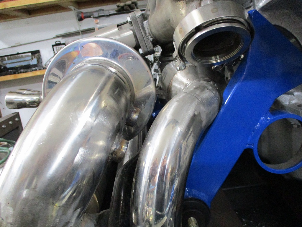
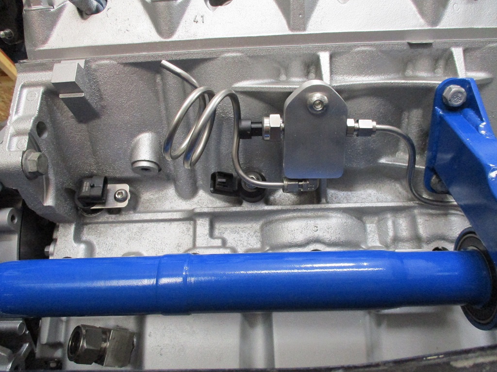
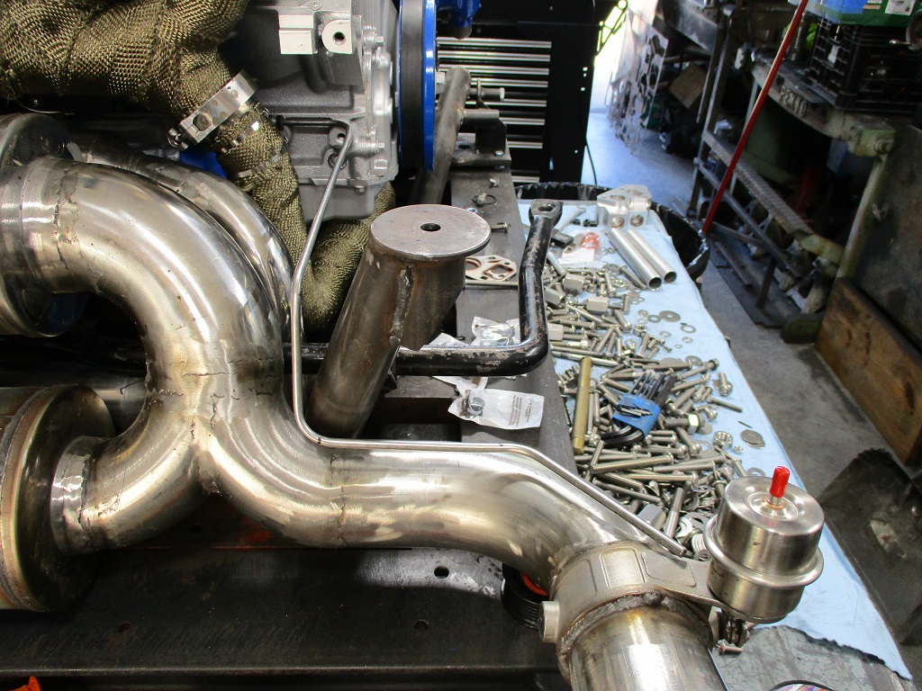
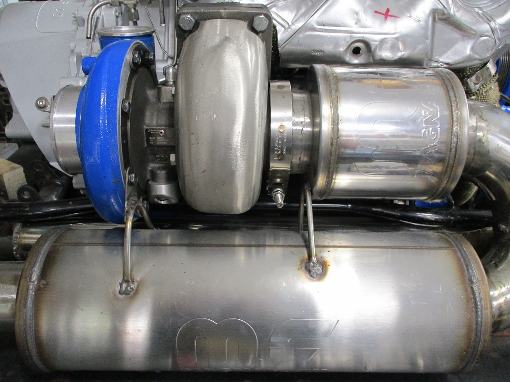
On the rear of the engine: Installed new axle seals in the transmission, 24X crank sensor, the intermediate shaft with a new intermediate support bearing, sand blasted and painted rear manifold, installed the compressor housing back on the turbo, and started to make an exhaust pressure manifold block.
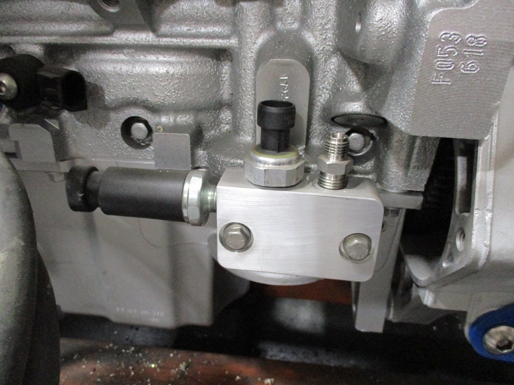
Finished the exhaust pressure manifold, installed the pressure sensor, ran the hard line from the exhaust manifold, and ran the hard line to the boost activated cut out.
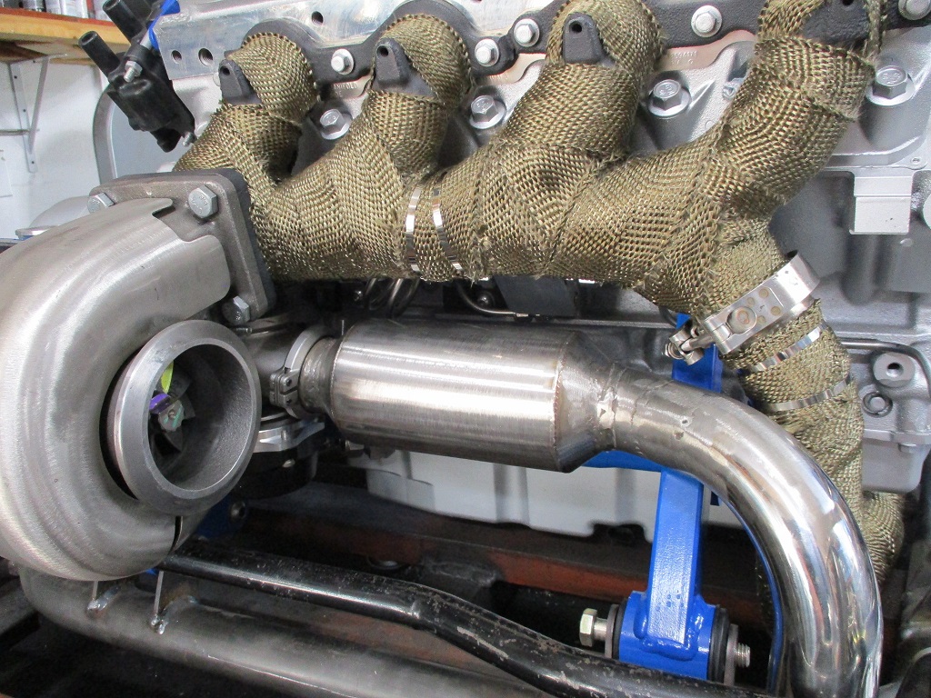
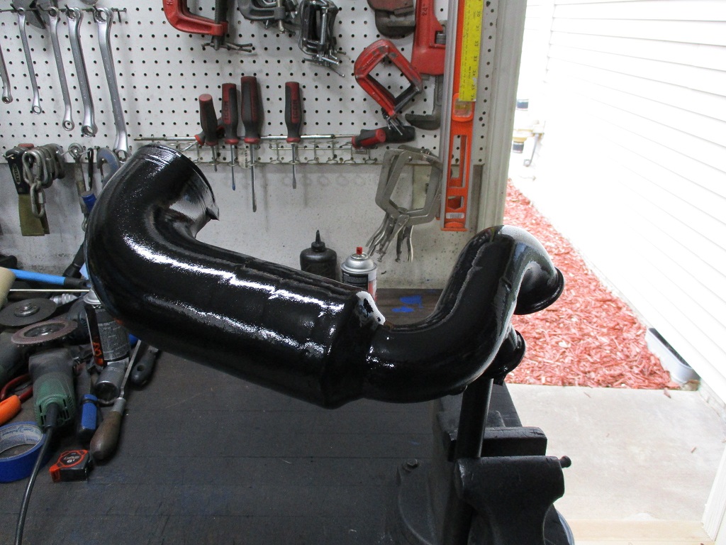
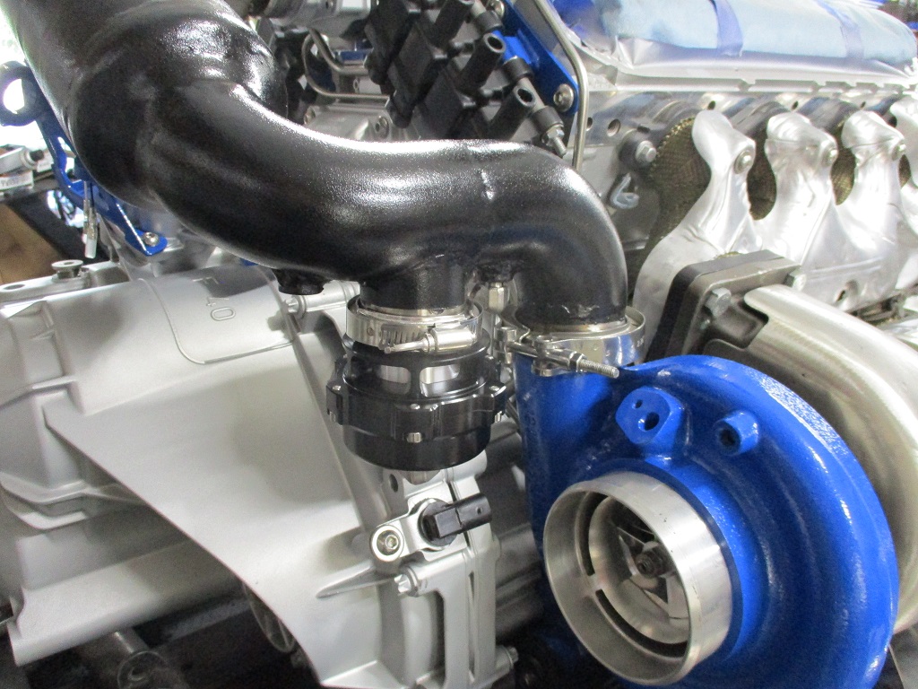
Then I wrapped the rear manifold, installed the manifold, crossover pipe, wastegate & wastegate muffler pipe, and turbo:
Set the exhaust in place and installed the manifold heat shield. Here you can also better see the route of the hard line to the cut out.
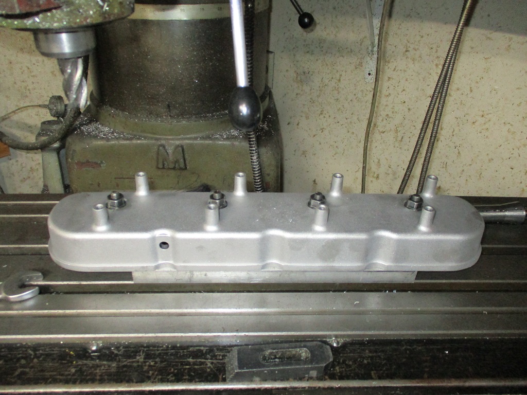
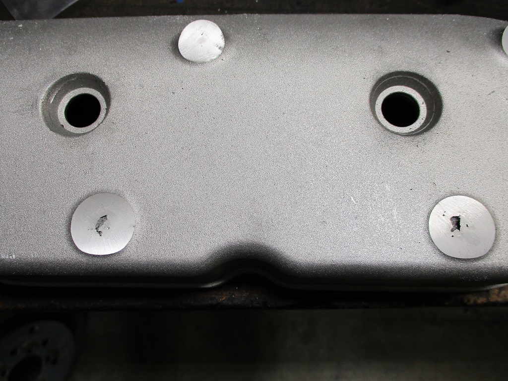
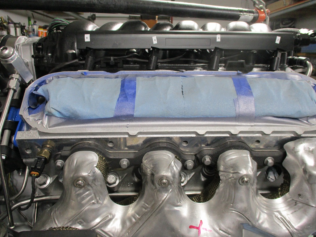
Started removing the coil bosses from another set of valve covers:
Several of the studs had porosity, so I am going to need remove a little more material and tig them up before the final smoothing.
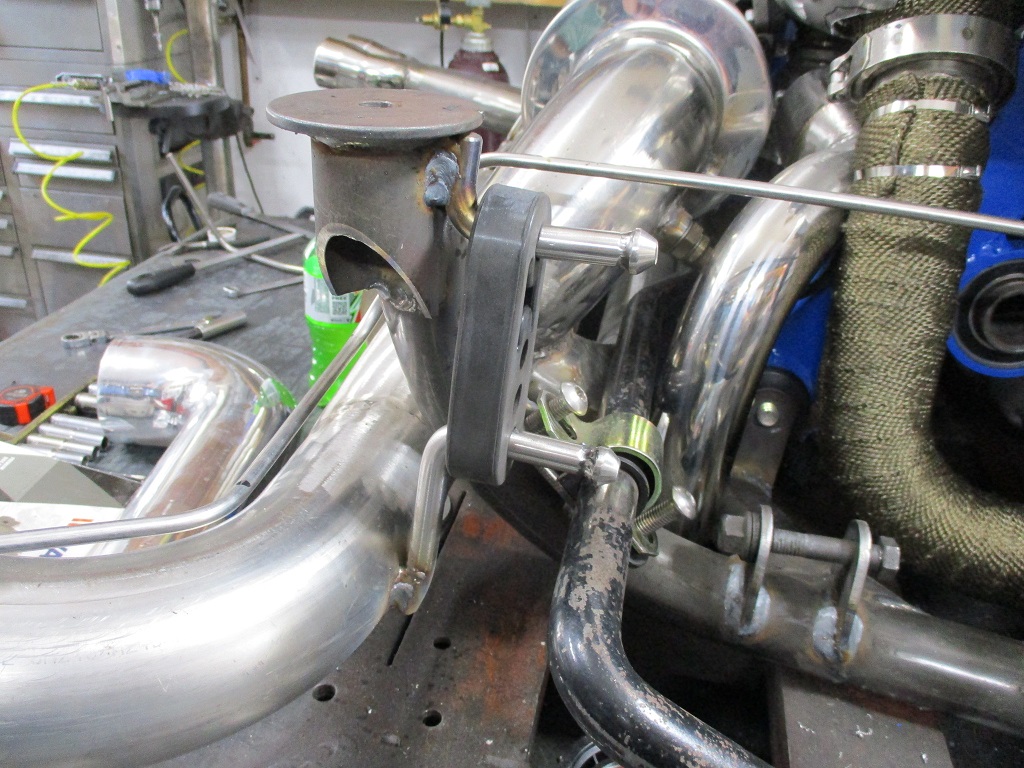
Fabbed up some hangers for the exhaust (still need a couple more to the cradle). Also installed the oil drain line:
Hooked up the oil feed line:
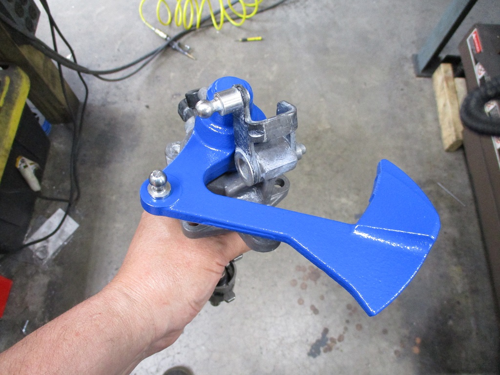
Started connecting the manual boost controller:
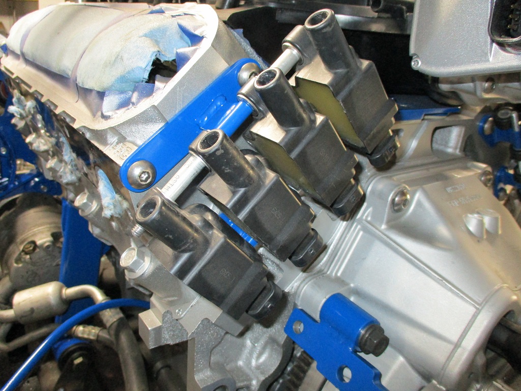
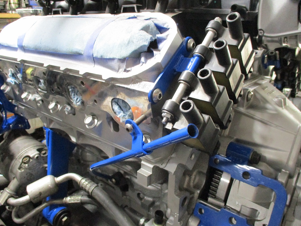
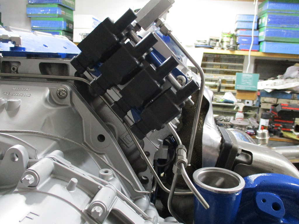
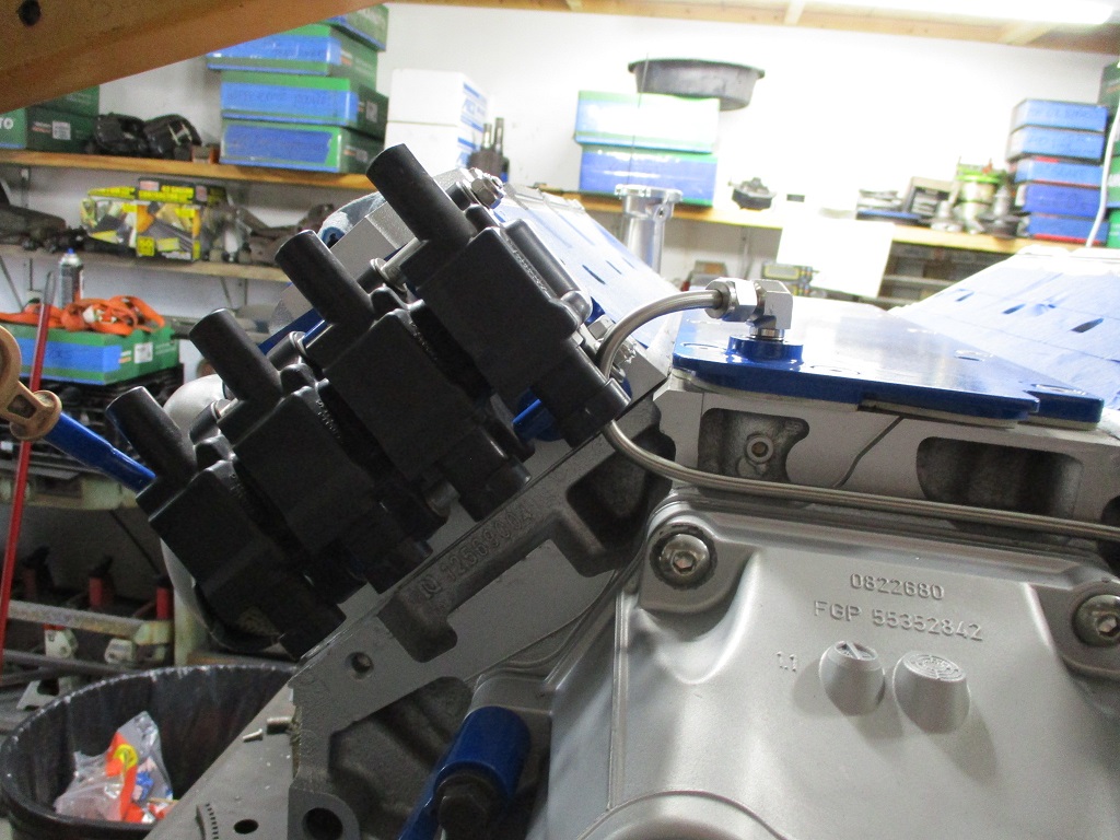
All coils mounted:
Started undercoating the warm pipe:
Spent a fair amount of time stripping all the paint off the shift lever. Got the shift lever painted, tomorrow will mask off and paint the lower section aluminum.
Getting the warm pipe and shifter done will allow me to install the shift bracket and the various sensors, lines and BOV, then I can move on to the intake, fuel rails, regulator, ect.
[This message has been edited by fieroguru (edited 06-13-2023).]
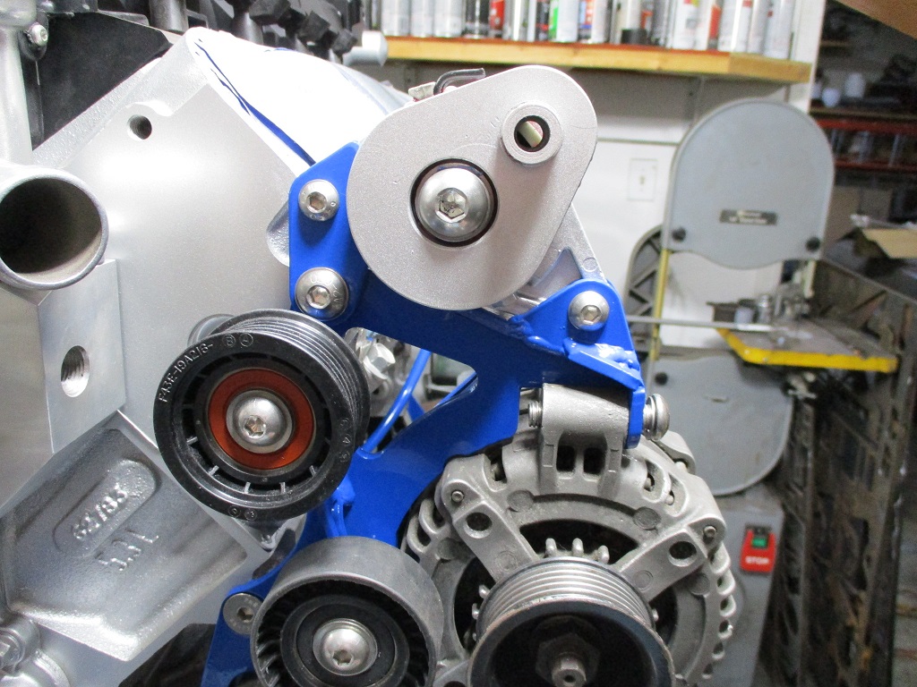
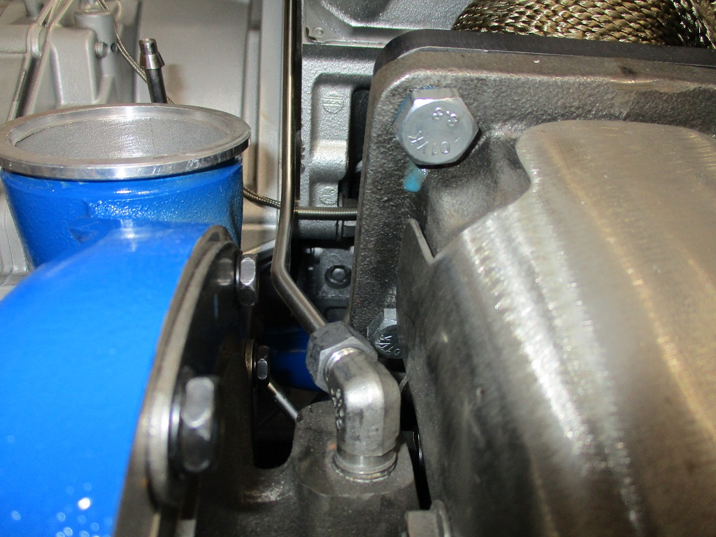
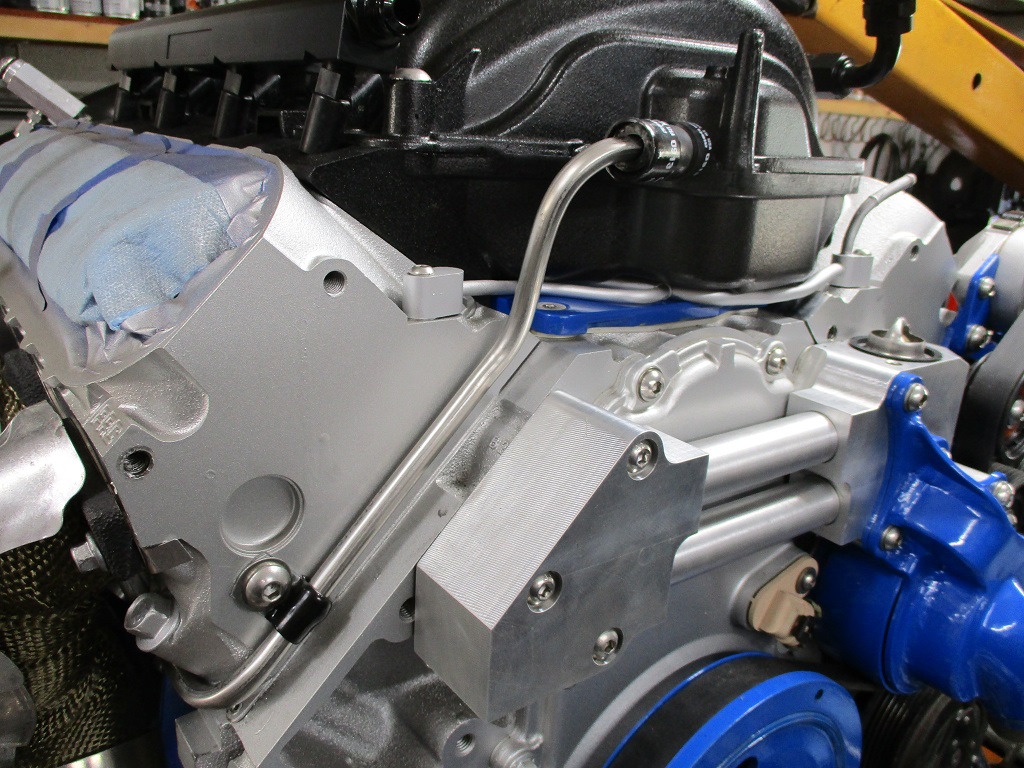
Routed the wire to the cam sensor and was planning to use a loop clamp, but ended up making a small aluminum guard to protect the wire from the belt and pulley.
Routed the heater hose and it clears the belt and pulley as well:
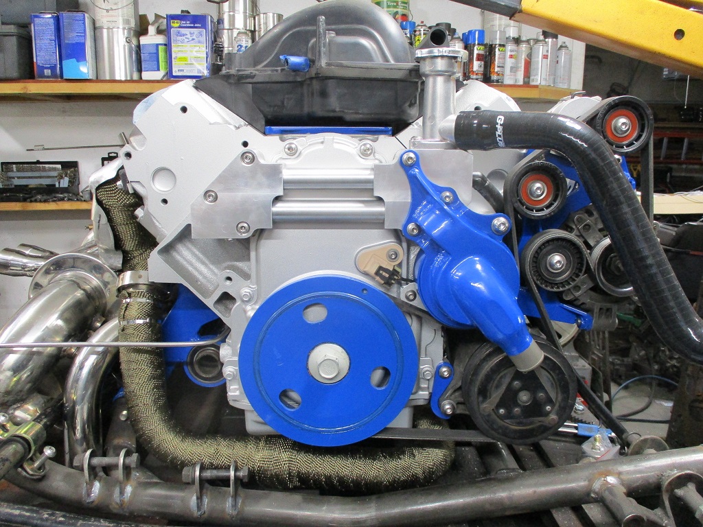
I am really happy with the visuals for this:
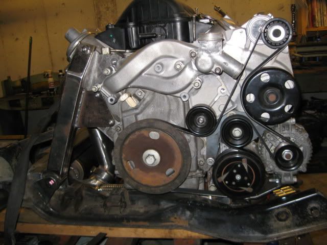
Compared to 12 years ago when I first reworked the accessory drive:
Compared to stock LS4:
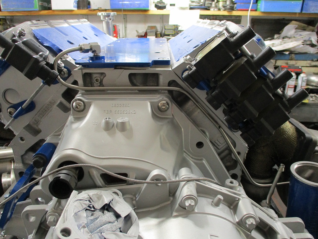
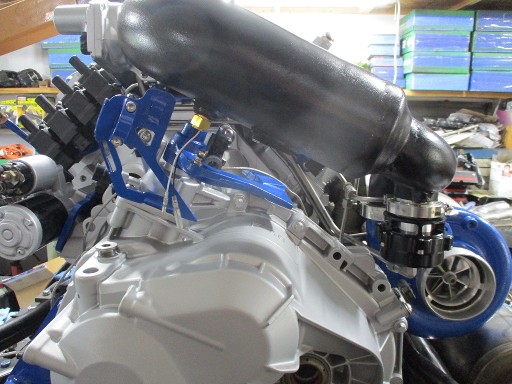
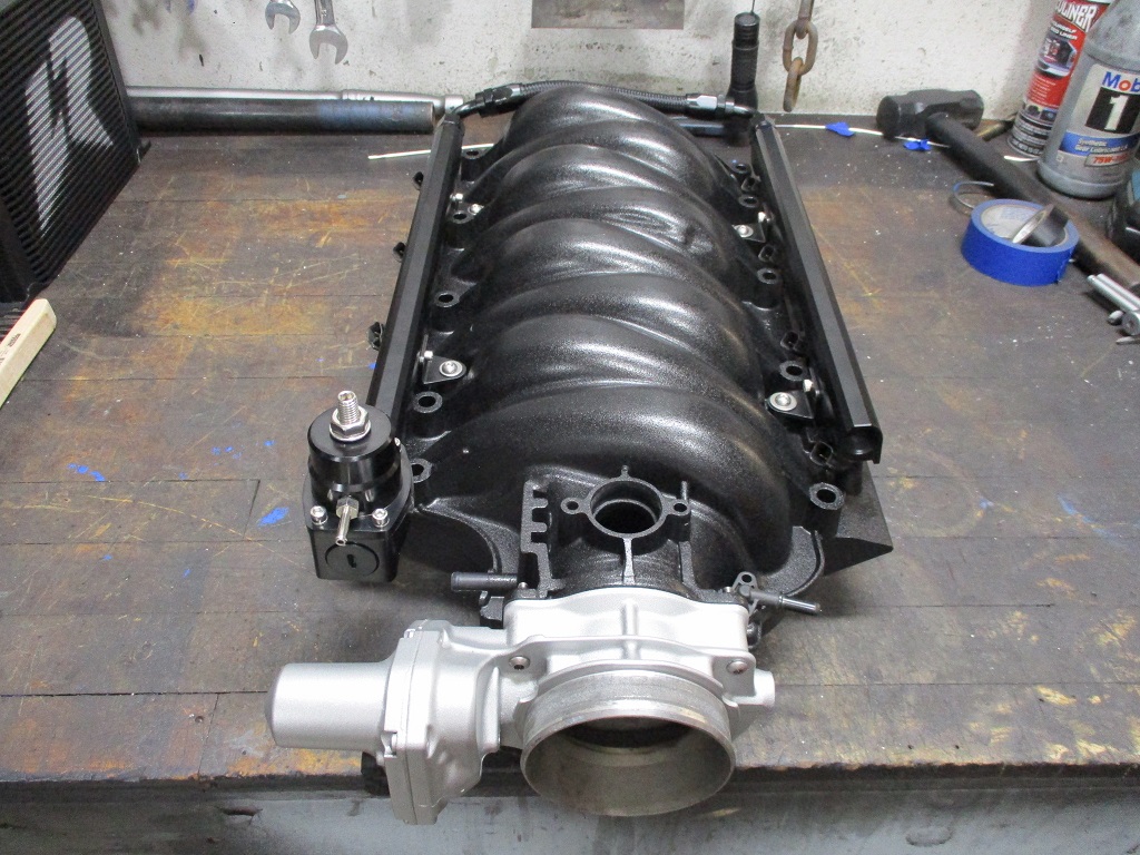
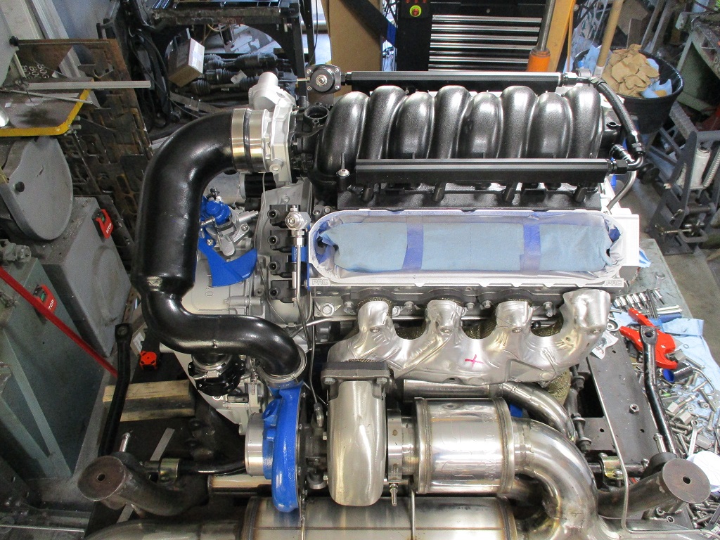
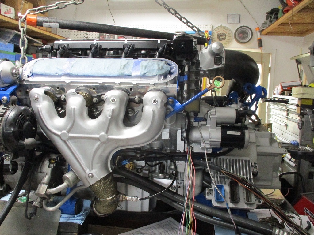
Installed the warm intake tube, blow off, temp sender, and boost reference line:
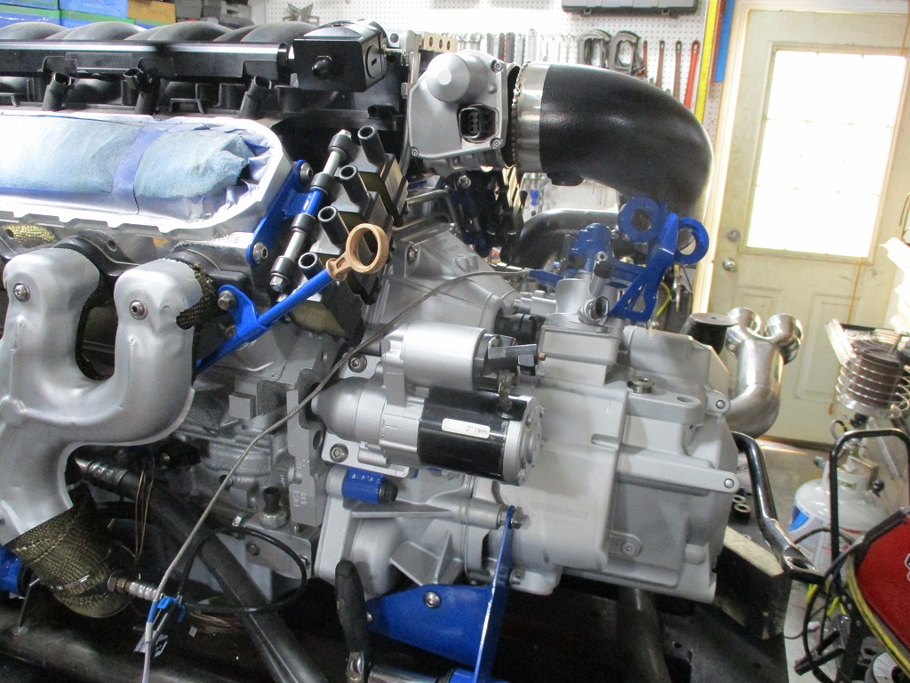
Installed the shifter assembly, shifter bracket, and starter:
Tomorrow is going to be a clean up the shop and fab day. I need to do some intake manifold modifications, fuel rail bracket modifications, make an ecm mount, weld some braces to the cradle, and try to tig up the valve covers.
I remember there was some issue with the one that came on my donor engine -- might have been interference with the intake. Looking awesome, as always man!!
I remember there was some issue with the one that came on my donor engine -- might have been interference with the intake. Looking awesome, as always man!!
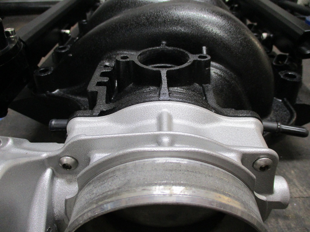
It is not a stock LS4 piece. The LS4 had the rear two blocked off and only used the front two steam ports. The 4 port version was from an early model, and I always though it was better to use all 4 corners. This one was massaged a bit to clear the DOD valley cover on my original swap and then some more to clear the LS2 dorman intake.
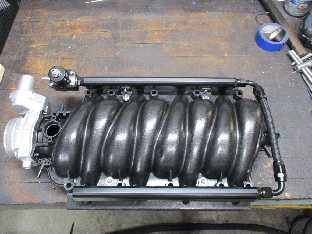
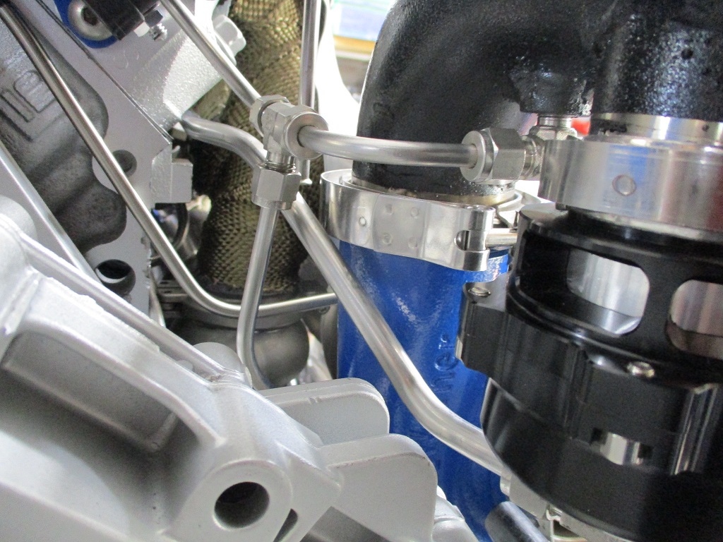
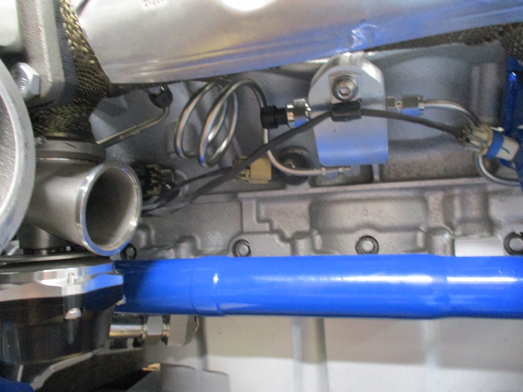
Went down a rabbit hole with the manifold like to the BOV... Wasn't happy with the plate on top and there was an unused vacuum port at the rear of the intake, so ran a new line under the rear manifold to the vacuum port:
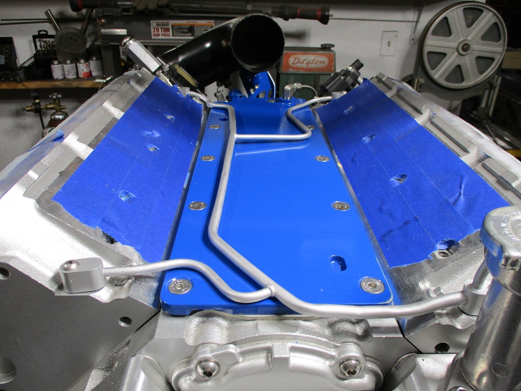
Then worked on the coolant crossover tube:
As you could see from the other pictures, the intake is now on as well:
Welded a nut to the exhaust to support the cutout boost line:
Welded a tab to the cradle to support the driver's side of the coolant crossover pipe:
Took the engine/transmission off the cradle so it could be cleaned and painted (also cleaned and painted the coolant crossover tube but didn't take a picture):
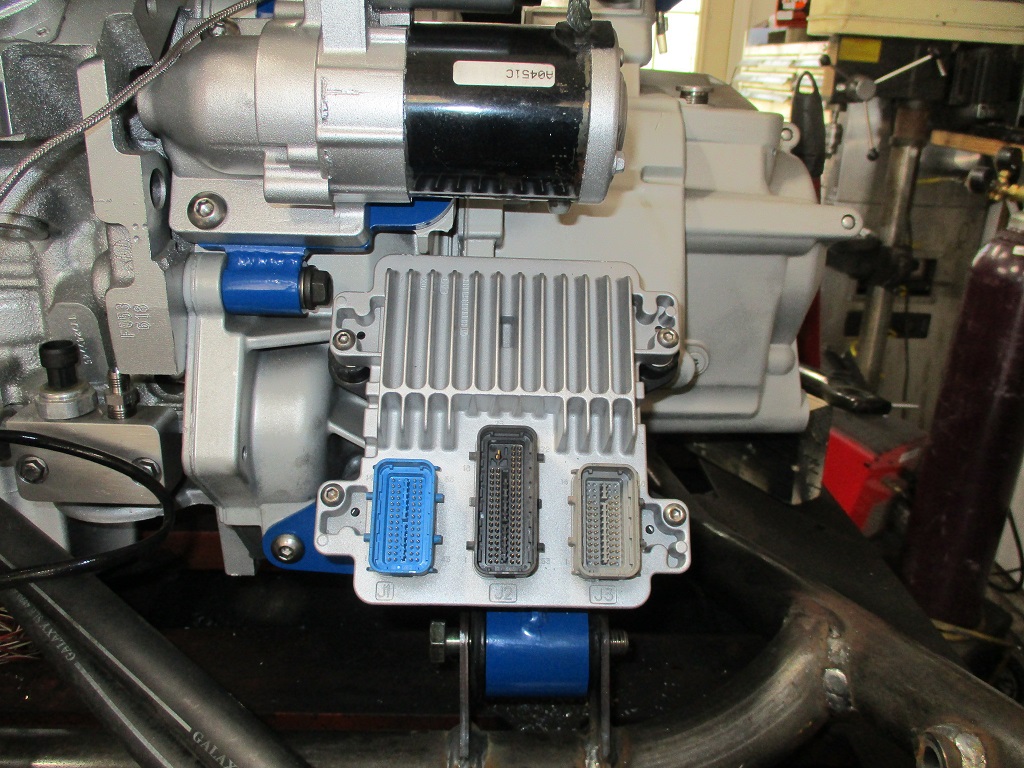
Set the engine/transmission down on some 4x4 blocks and started plugging in some of the connectors:
Harness work is probably my least favorite part of engine swaps... but keeping the harness tidy and mostly hidden improves the overall visual impact of the swap, so it is a necessary evil.
Here is a list of sensors/components that have the wires connected, looped and routed (not terminated). Cam sensor, Alternator (power + control wiring), A/C compressor clutch and pressure switch, bank 1 knock sensor, bank 1 O2 sensor, oil pressure sensor, oil pressure gauge, bank 2 knock, bank 2 O2, crankshaft sensor, temp sensor & gauge, VSS.
Still a lot more to complete, but not a bad first day on the harness work..
Front side of the engine - pretty much all done. The top wire is the power wire with 200A fusible link between the Alternator and starter. The lower one is the actual harness.
Here is the front side with the manifold and AC hose back on. You can also see the injector harness for bank 1. It runs under the fuel rail and zig zags between the intake bolt bosses and the injectors. It should be virtually invisible from the top beyond the small loops from the injectors to the harness below.
Here is rear side (bank 2) injector harness as well the temp sensor & gauge wiring:
Here is the underside of bank 2. Still need to finish looming them together. I am thinking of running the wideband and the exhaust back pressure sensor separately in case I want to remove them later.
It has been a very productive vacation! It will be a couple of days before I can get back at the harness work.