Originally posted by Trinten: Put me down for one of the water manifolds.
quote
Originally posted by Bob2112: I'd love to buy one as soon as you have them ready!
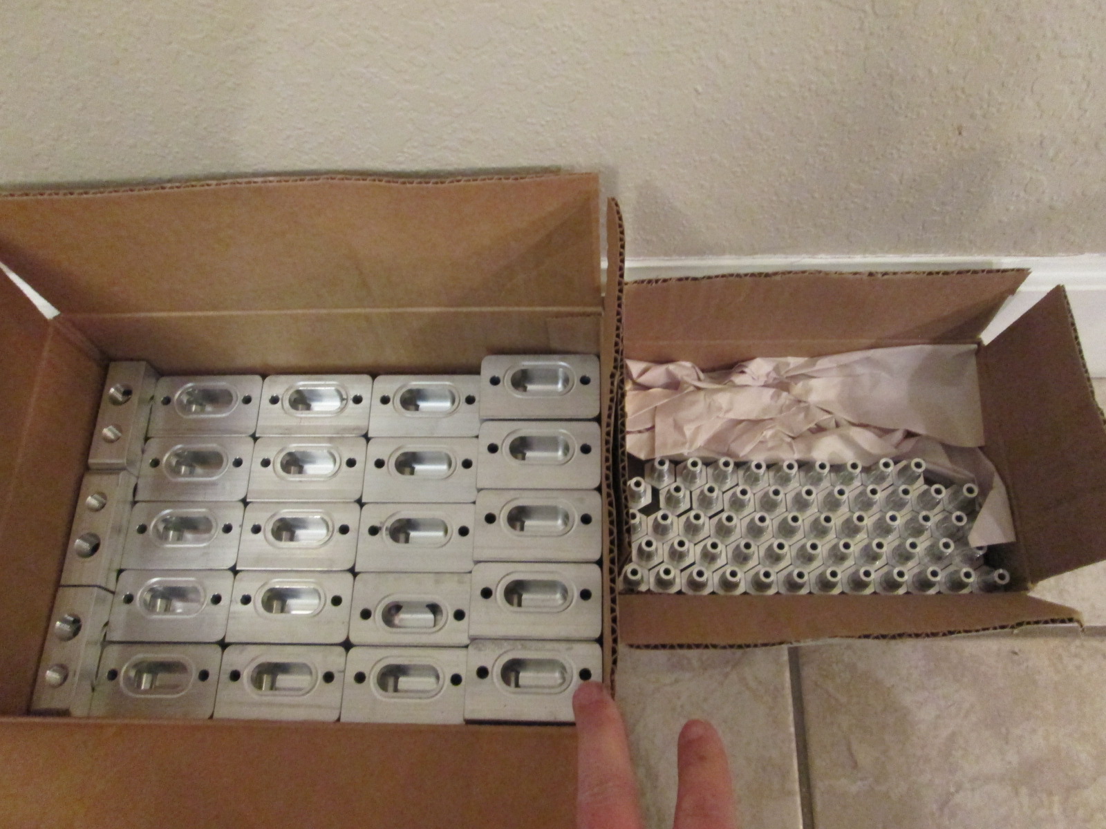
Once I get the first two prototypes here and fully assembled, I will take some pictures and start another thread for people to voice their interest. I won't need to take any payment until the first back is in my posession, then I will let everyone know they are available.
quote
Originally posted by Will: How are you going to seal the tubes to the blocks? O-rings?
Yes, the blocks have internal o-ring grooves that the tubes will slide through when they are assembled.
[This message has been edited by fieroguru (edited 12-30-2020).]
While the car is down for the drivetrain upgrades, I have also been pondering some interior upgrades, primarily electronic tech...
SInce the car is used a lot on Power Tours and road trips, I am always using my phone for GPS. I had a very close call on the 2016 HRPT where my charger cable on my cell phone went bad, the battery on the phone was running down, and I had to swap batteries with the a friend I was traveling with so I could get to my hotel (and buy another charger cable). After that I started carrying spare batteries. The other issue is that location with the cell phone plugged in would get hot and sometimes overheat and start turning off functions.
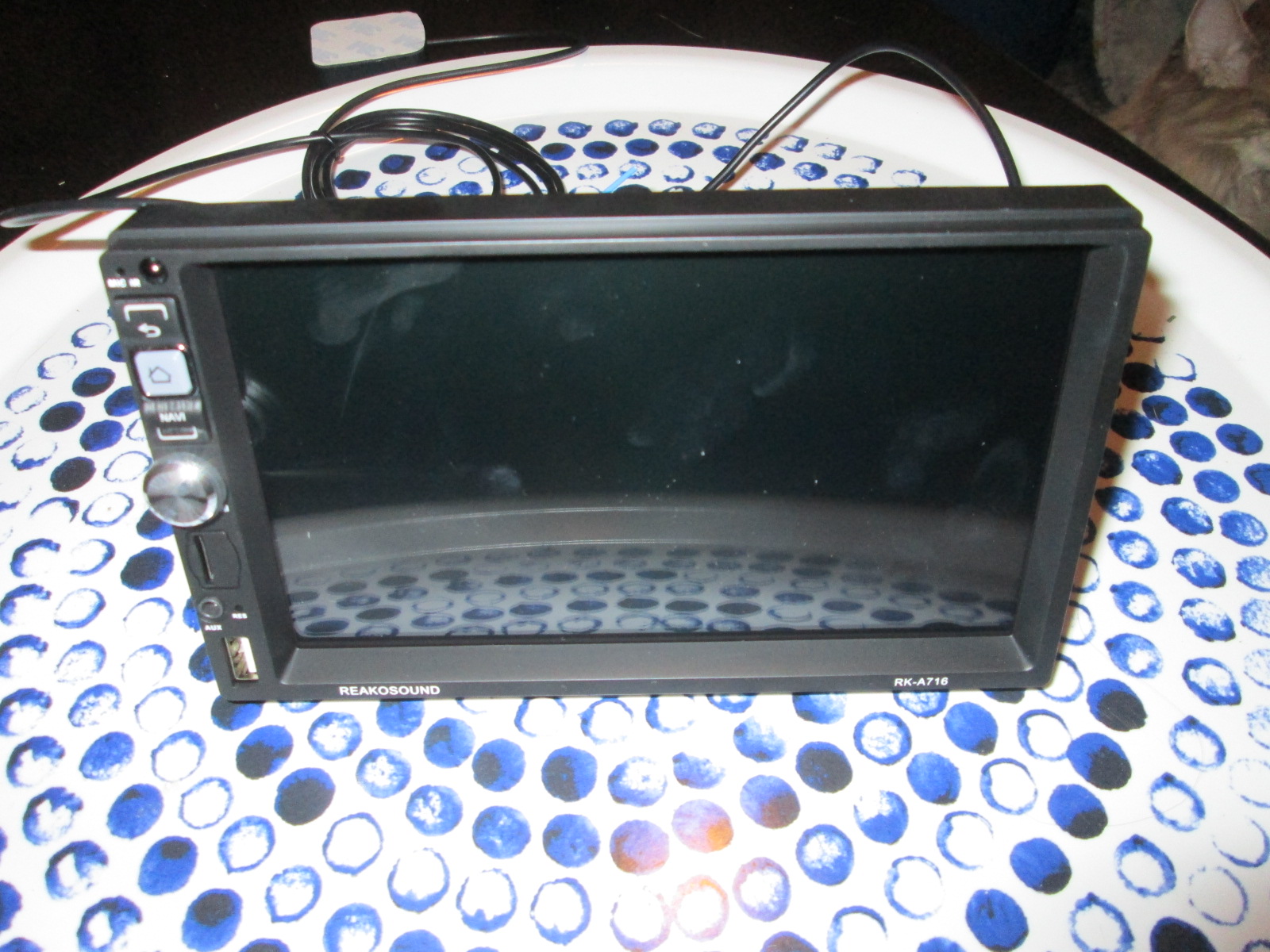
What would be really handy would be to have a 2 DIN head unit with GPS, backup camera, MP3, WiFi, hands free calling, etc. Beside the stock stereo location not being setup for 2 Din w/o some hackery, the stock location sucks for GPS use. So I have been looking at other creative means for the multimedia upgrade...
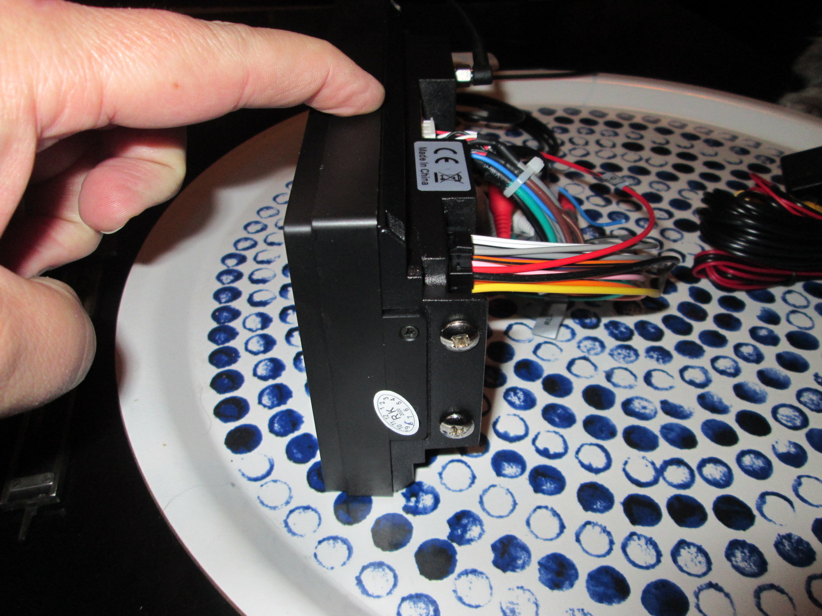
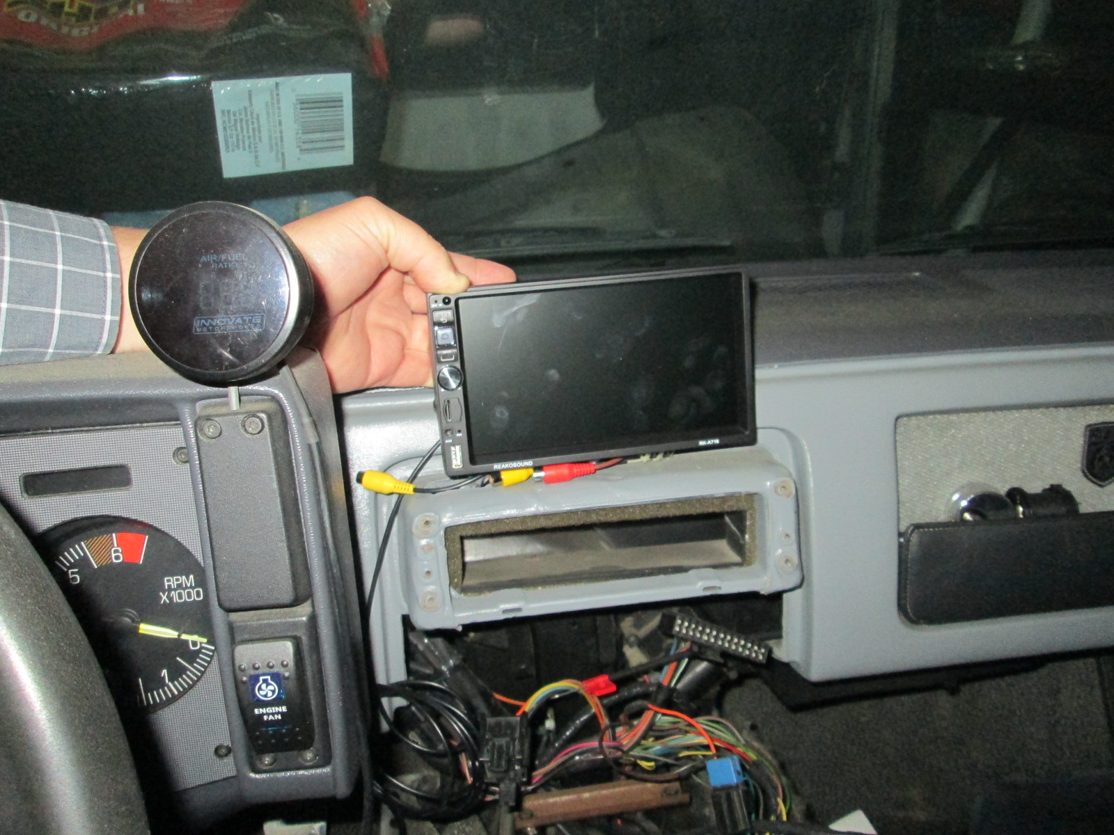
While searching for options, I came across some shallow 2 Din head units with a lot of the features I was looking for. They delete the CD/DVD capability and once that is done, they can be as shallow as 2" deep. With this minimal depth, in theory they could be mounted where the aux gauges are. This would put the screen in a much better location for GPS, but it will require making a bracket to mount the head unit, fabricating an enclosure of some kind, and running several wires down past the HVAC ductwork.
Do you mind sharing the dimensions and brand/model? I have the double DIN with Amida's interior. I wanted to put in an Android powered head unit (like a Pumpkin or something similar), and get a 4G dongle and data-only plan on a different carrier than my cell phone. Worst case, if the head unit looses wifi, I can hotspot off my phone. I've seen the "Android Auto" thing, but I've opted to leave the new "Google Assistant" turned off, which apparently impacts that, hence trying to stick with an Android based unit (real time map updates and such).
And thanks for the heads up on the water manifold! I'll try to scan the mall now and then!
Here is a link to the radio. Amazon has a lot of different ones. I wanted one with a dedicated subwoofer output and didn't want a complete touch screen https://www.amazon.com/gp/p...=AZV2Q3JGU683F&psc=1
When I get the first two water manifolds, I will post the pictures in this thread first.
any thought on having the water manifold cast and then machined? might be less expensive than billet, and allow for one piece design.
------------------ "I am not what you so glibly call to be a civilized man. I have broken with society for reasons which I alone am able to appreciate. I am therefore not subject to it's stupid laws, and I ask you to never allude to them in my presence again."
Originally posted by ericjon262: any thought on having the water manifold cast and then machined? might be less expensive than billet, and allow for one piece design.
Not really, I don't have the needed time to devote to that process.
Cool coolant enters the manifold at the bottom left hose connection where it is split and flows to both sides of the engine block through the lower section (and tube) of the water manifold. Once the coolant is in the engine, it goes through the block and up through the heads. Hot coolant reenters the manifold in the top section and moves to the right side where flow (and engine temp) is controlled by the thermostat. As the coolant flows through the thermostat, it will enter the coolant fill neck and upper hose that will send the coolant back to the radiator. There is also a heater core supply nipple on the right block that will send hot coolant to the heater core and back to the coolant tube from the radiator that sends cool water back to the engine.
If the water pump is installed after the lower passenger side coolant tube and before the engine, it will mimic the stock coolant flow path of the 87 and 88 Fiero, just with an electric water pump supplying the coolant circulation. You can also install the water pump up front, but the heater core cool return will need to be plumbed in front of the water pump for the coolant to circulate as a bypass.
This does change the location of the thermostat for the LS engines. Stock LSx the thermostat is on the water inlet side, so it controls water entering the engine. This setup controls water exiting the engine and was the industry standard method of engine temp control for 50+ years... so it works well (when I modified my stock LS4 water pump assembly, I moved the thermostat to the exit side of the coolant flow, so my swap has always ran the thermostat in this location).
It satisfies all the coolant plumbing requirements for the LSx engine in a very compact, lightweight, and clutter free manner. It will only have 2 visible hoses in the engine bay (1 if you hide the heater core supply hose under the return hose to the radiator).
[This message has been edited by fieroguru (edited 01-16-2021).]
It mimics the stock coolant flow path of the 87 and 88 Fiero, just with an electric water pump supplying the coolant circulation. This does change the location of the thermostat for the LS engines. Stock LSx the thermostat is on the water inlet side, so it controls water entering the engine. This setup controls water exiting the engine and was the industry standard method of engine temp control for 50+ years... so it works well (when I modified my stock LS4 water pump assembly, I moved the thermostat to the exit side of the coolant flow, so my swap has always ran the thermostat in this location).
Are you using the LS thermostat in a recirculating capacity?
Old school thermostat (4.3 CPI application) with the coolant bypass through the heater core.
I would have thought with the position of your thermostat and the layout of the block, you'd be able to recirculate like the stock system.
Recirculation warms the engine up more evenly, and recirculating thermostats tend to flow more water than older style on/off thermostats, which is beneficial for making the best use of a Fiero's relatively small radiator.
However, you'd need two heater connections on your water log, as T-ing the heater return into the radiator return wouldn't work (BTDT with the Northstar)
[This message has been edited by Will (edited 01-14-2021).]
Originally posted by fireboss: in case i missed it could you explain the electric waterpump set up
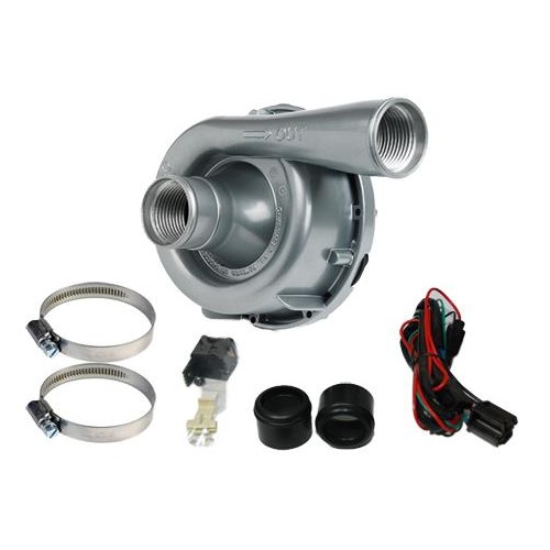
Any electric water pump that flows 40+ gpm will work, but since the manifold only has a single inlet, water pumps with a single outlet keeps things simple.
I am planning to install this one up front between the radiator outlet and the under chassis coolant tube on the passenger side. They also have a programmable controller for it if you want to go that route.
Originally posted by Will: I would have thought with the position of your thermostat and the layout of the block, you'd be able to recirculate like the stock system.
Recirculation warms the engine up more evenly, and recirculating thermostats tend to flow more water than older style on/off thermostats, which is beneficial for making the best use of a Fiero's relatively small radiator.
However, you'd need two heater connections on your water log, as T-ing the heater return into the radiator return wouldn't work (BTDT with the Northstar)
I prefer to try and use OEM parts, especially when it comes to things like electric water pumps, they are tested WAY harder by the OEM's and general populace that abuses the crap out of their cars, supposedly the BMW pump in this video is an inexpensive OE option.
That being said, you'll need a spare PWM output to control it, idealy something linked to a table based on engine speed and temperature probably, with triggers based on throttle movement. you may also be able to get a standalone controller, I didn't watch the whole video, I'm probably going to keep a mechanical pump.
------------------ "I am not what you so glibly call to be a civilized man. I have broken with society for reasons which I alone am able to appreciate. I am therefore not subject to it's stupid laws, and I ask you to never allude to them in my presence again."
Any electric water pump that flows 40+ gpm will work, but since the manifold only has a single inlet, water pumps with a single outlet keeps things simple.
I am planning to install this one up front between the radiator outlet and the under chassis coolant tube on the passenger side. They also have a programmable controller for it if you want to go that route.
Are you just going to plumb the heater in directly at the pump instead of going back to the engine?
I'd also be concerned about the flow area in that, whatever a AN-16 (12) is, it's smaller than the 1 1/4" - 1 1/2" inlets on OE pumps, as well as the 1 1/4 coolant tube. I say "whatever that is" because it would have to have the 37 degree seat integral in the housing to be an AN fitting. Pipe thread is far more sensible in this application, but the connection should be larger than -16.
[This message has been edited by Will (edited 01-15-2021).]
Are you just going to plumb the heater in directly at the pump instead of going back to the engine?
I'd also be concerned about the flow area in that, whatever a AN-16 (12) is, it's smaller than the 1 1/4" - 1 1/2" inlets on OE pumps, as well as the 1 1/4 coolant tube. I say "whatever that is" because it would have to have the 37 degree seat integral in the housing to be an AN fitting. Pipe thread is far more sensible in this application, but the connection should be larger than -16.
O-ring base fittings (ORB), are sized in the same manner, and have the same thread diameter and pitch. in fact, in a pinch once, when I needed a -6 ORB to -6 AN flare, and didn't have one, I put an o-ring on one end of a -6 union and installed it. was it right? no, did it work without damaging anything? yes.
------------------ "I am not what you so glibly call to be a civilized man. I have broken with society for reasons which I alone am able to appreciate. I am therefore not subject to it's stupid laws, and I ask you to never allude to them in my presence again."
Originally posted by ericjon262: I prefer to try and use OEM parts, especially when it comes to things like electric water pumps, they are tested WAY harder by the OEM's and general populace that abuses the crap out of their cars, supposedly the BMW pump in this video is an inexpensive OE option.
I hear you on OEM R&D and reliability and I also have a strong preference for mechanical water pumps (which I will eventually pair with this coolant manifold).
That pump is definitely worth looking into to a little further. The E40 ecm has a PWM option for fan control that I could likely repurpose.
quote
Originally posted by Will: Are you just going to plumb the heater in directly at the pump instead of going back to the engine?
I'd also be concerned about the flow area in that, whatever a AN-16 (12) is, it's smaller than the 1 1/4" - 1 1/2" inlets on OE pumps, as well as the 1 1/4 coolant tube. I say "whatever that is" because it would have to have the 37 degree seat integral in the housing to be an AN fitting. Pipe thread is far more sensible in this application, but the connection should be larger than -16.
I updated the water pump flow description above as the plumbing is slightly different depending on where you mount the water pump (by radiator or by engine). The hot supply to the heater core will always come from the water manifold on the engine right below the thermostat (under the fill neck). The cool return from the heater core needs to merge back into the coolant flow ahead of the water pump so the pump will circulate it.
The Davies Craig pump can accept hoses over the housing w/o needing to use any threaded nipples or AN fittings. Also, the LS engines have an internal restriction on the outlet ports. While the large round hole in the block is about 1.06" in diameter, it is blind and uses a 3/4" or smaller hole on the side for coolant flow exiting the heat.
The PWM output for the fan would probably be almost perfect for a water pump, as long as you have a binary output to control the fan still available. I love having an MS3 because I can make outputs do whatever I want them to do.
------------------ "I am not what you so glibly call to be a civilized man. I have broken with society for reasons which I alone am able to appreciate. I am therefore not subject to it's stupid laws, and I ask you to never allude to them in my presence again."
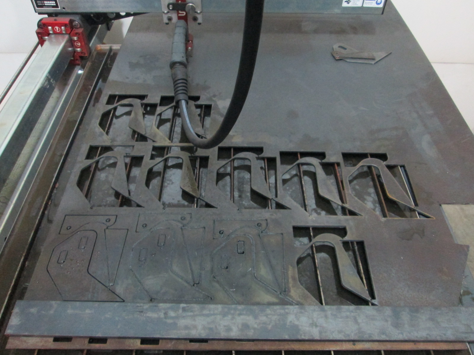
I have the CNC Plasma table pretty dialed in now for the 1/8" mild steel brackets. This is a video of cutting the 3 flat parts for the F40 shifter bracket.
I have the first round of test cuts for the 3/8" thick material done, just waiting for some larger pieces of 3/8" to arrive and I will make some more LS4 Starter Mounts.
[This message has been edited by fieroguru (edited 01-24-2021).]
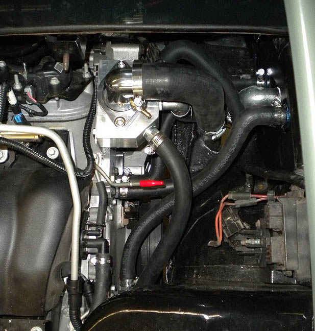
OK, how does your water manifold work different from Archies setup? Not that one is better, just trying to understand how his works and how yours works. Here a pic of the setup in my LS3 car. As I understand it, the two holes at the top of the motor side, exit out to the box with the thermostat, which also has one of the heater hoses attached and lead to/from the radiator. The bottom holes on the motor side lead to the water pump with is mounted behind the sheet metal where the old expansion tank was located, it also has an out to/from the radiator. Not sure which way it flows, I never remember which is to/from the radiator and which side has hot/cool water? Does your setup just make the "two" hoses into "one" on each side??? Thanks again.
[This message has been edited by qwikgta (edited 01-26-2021).]
Originally posted by qwikgta: OK, how does your water manifold work different from Archies setup? Not that one is better, just trying to understand how his works and how yours works. Here a pic of the setup in my LS3 car. As I understand it, the two holes at the top of the motor side, exit out to the box with the thermostat, which also has one of the heater hoses attached and lead to/from the radiator. The bottom holes on the motor side lead to the water pump with is mounted behind the sheet metal where the old expansion tank was located, it also has an out to/from the radiator. Not sure which way it flows, I never remember which is to/from the radiator and which side has hot/cool water? Does your setup just make the "two" hoses into "one" on each side??? Thanks again.
It doesn't work any differently. Electric water pump pushes coolant into the engine in the lower ports, hot coolant comes out the top ports, is controlled by a thermostat on the outlet, and sends coolant to the radiator and heater core. Both setups fundamentally control the water flow and engine coolant temperature in the same manner.
Mine design is more space efficient and uses fewer hoses/connections. I am more than a little obsessed with keeping wiring, hoses, and other clutter out of the engine bay as much as possible.
I am more than a little obsessed with keeping wiring, hoses, and other clutter out of the engine bay as much as possible.
This is SO true, and so awesome for any of his customers. He did such a crazy-good job at hiding the wiring in the EFI setup he did for me, that I got top points for it in a judged car show (didn't know it was going to be judged... so scored low in everything but the engine bay becaue zero-prep.) and actually had someone ask me if it was a carb setup just made to look like EFI!
Super busy weekend with customer orders.... but it did give me the opportunity to use the plasma table some more for starter brackets and some tap guide fixtures.
[This message has been edited by fieroguru (edited 01-31-2021).]
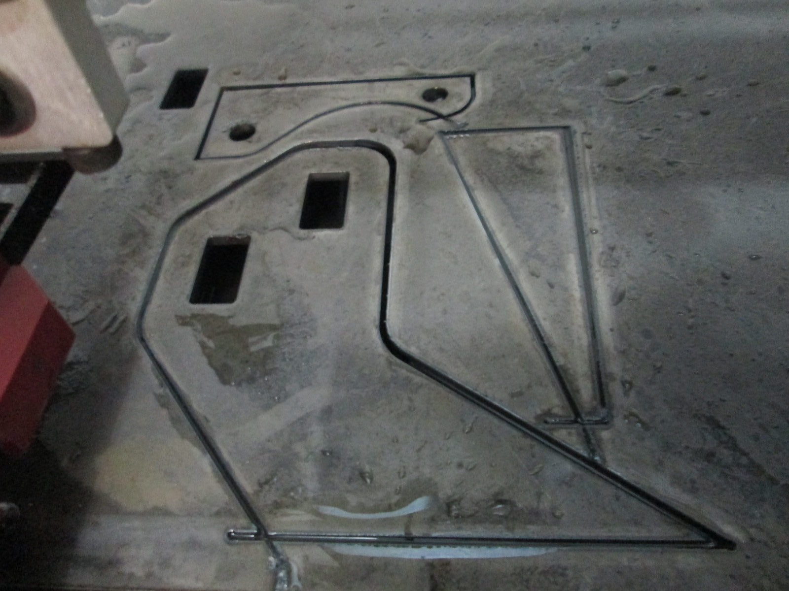
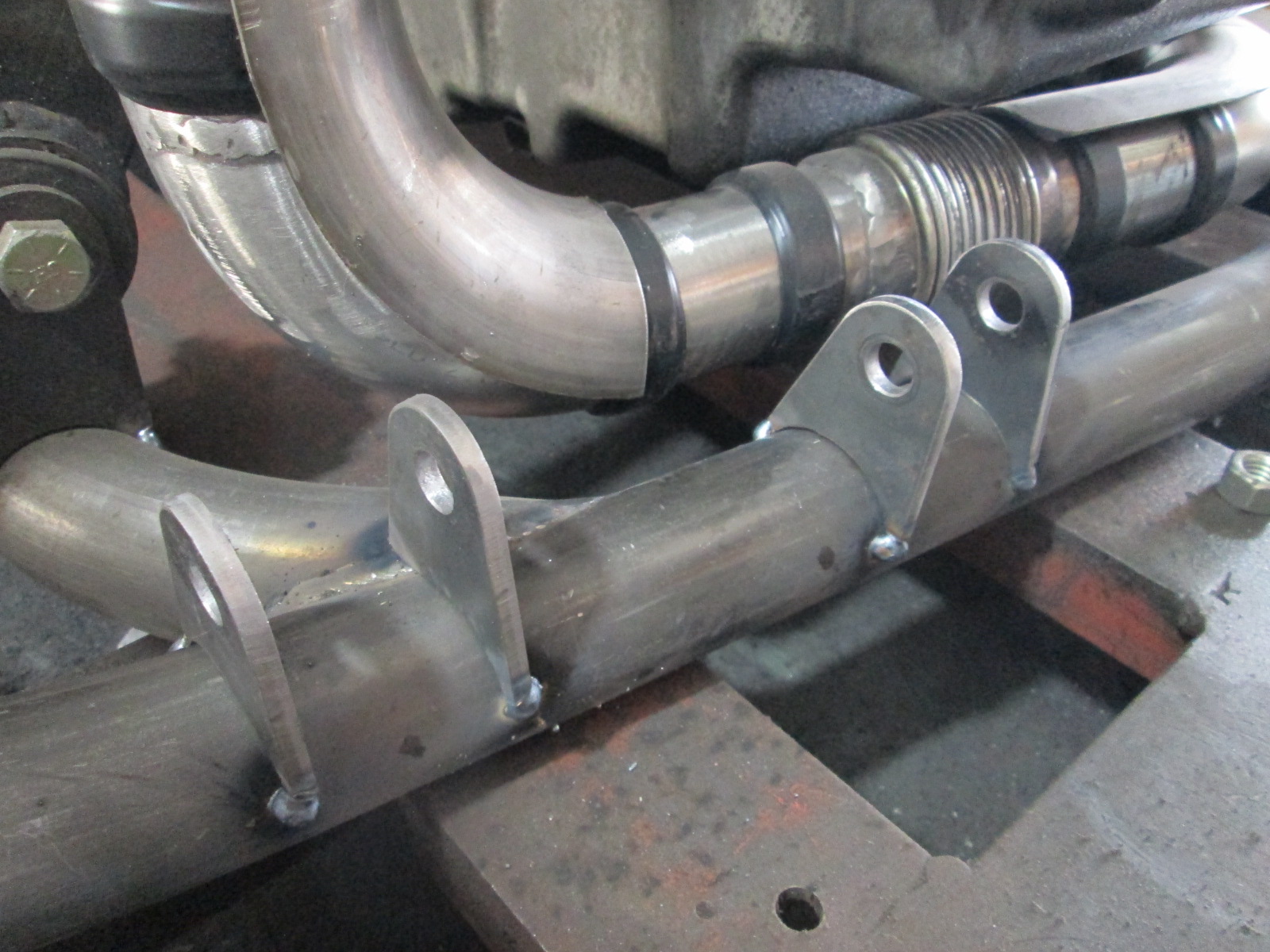
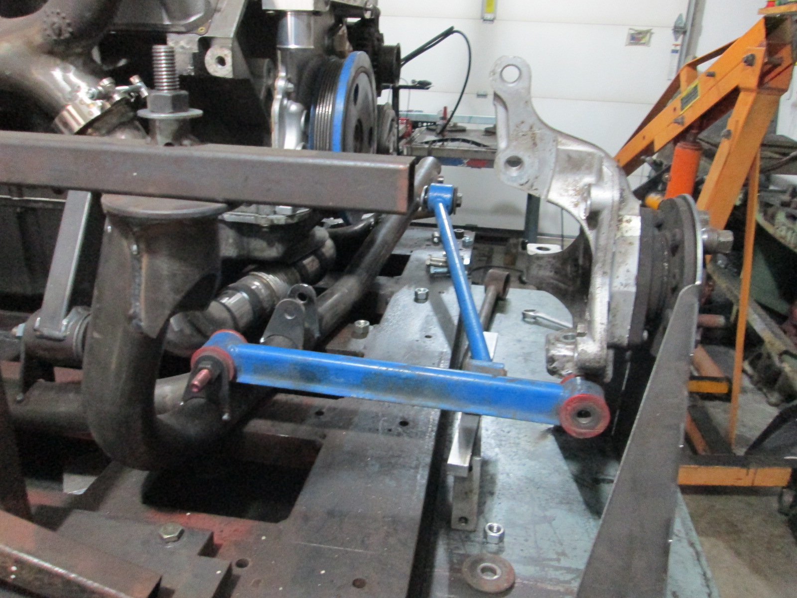
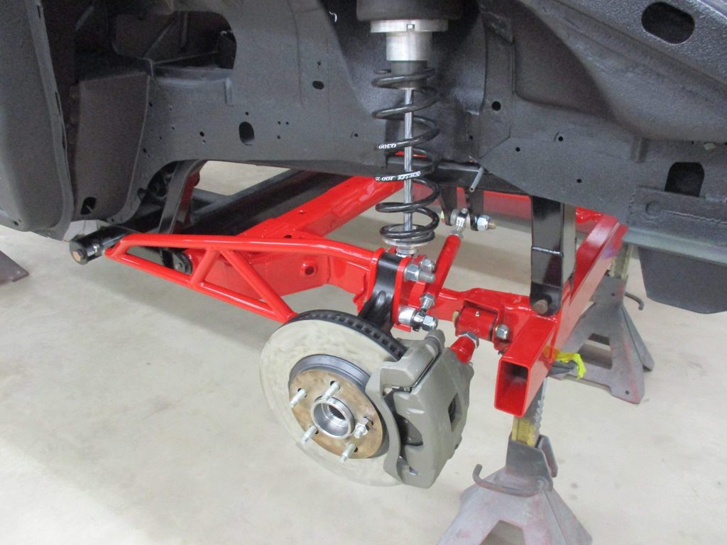
I can't remember the last time I had some free time to work on my own swap... but had a few hours today to mess with it. I decided to use the plasma table to make the lateral link tabs for the tubular cradle.
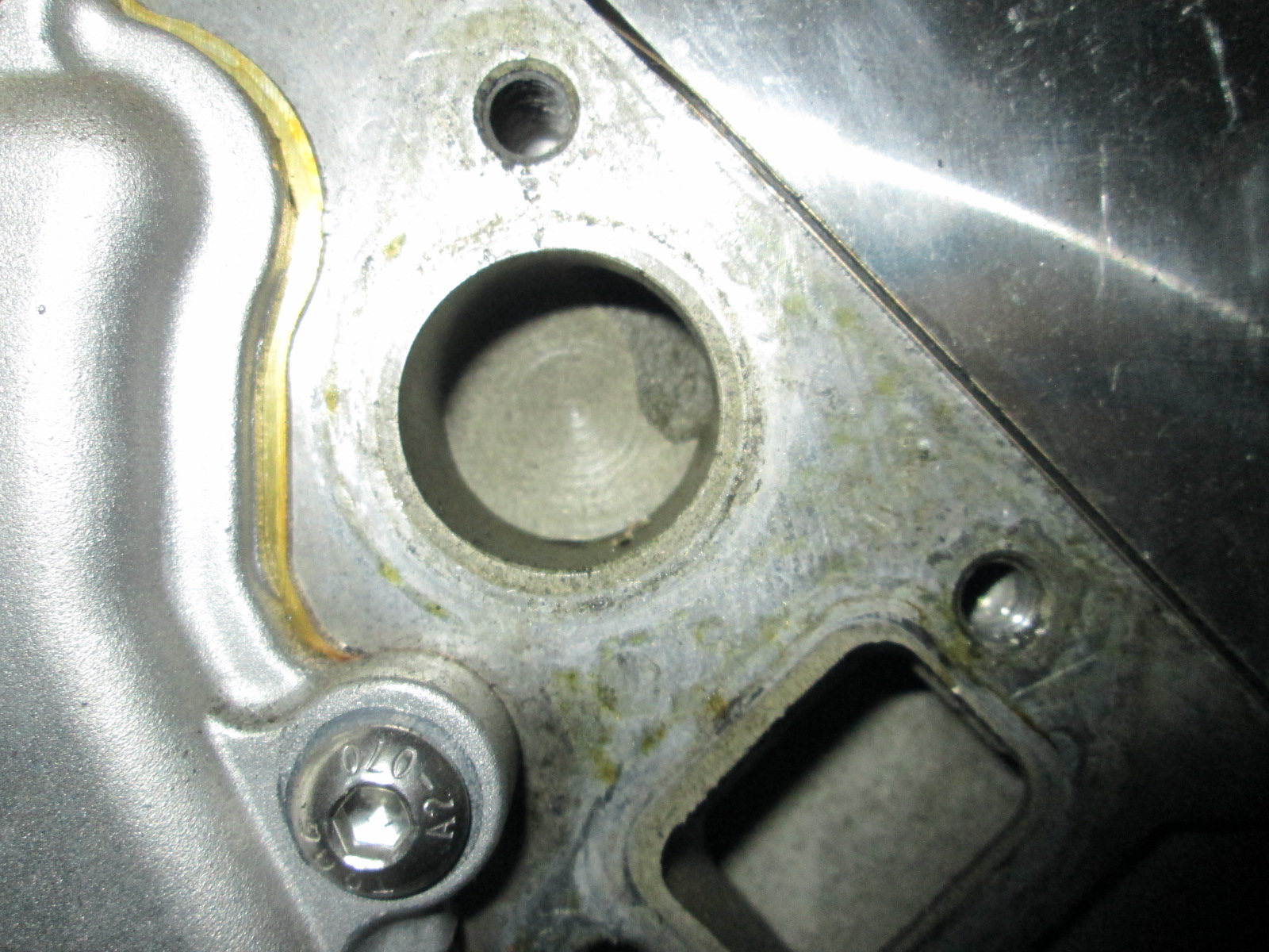
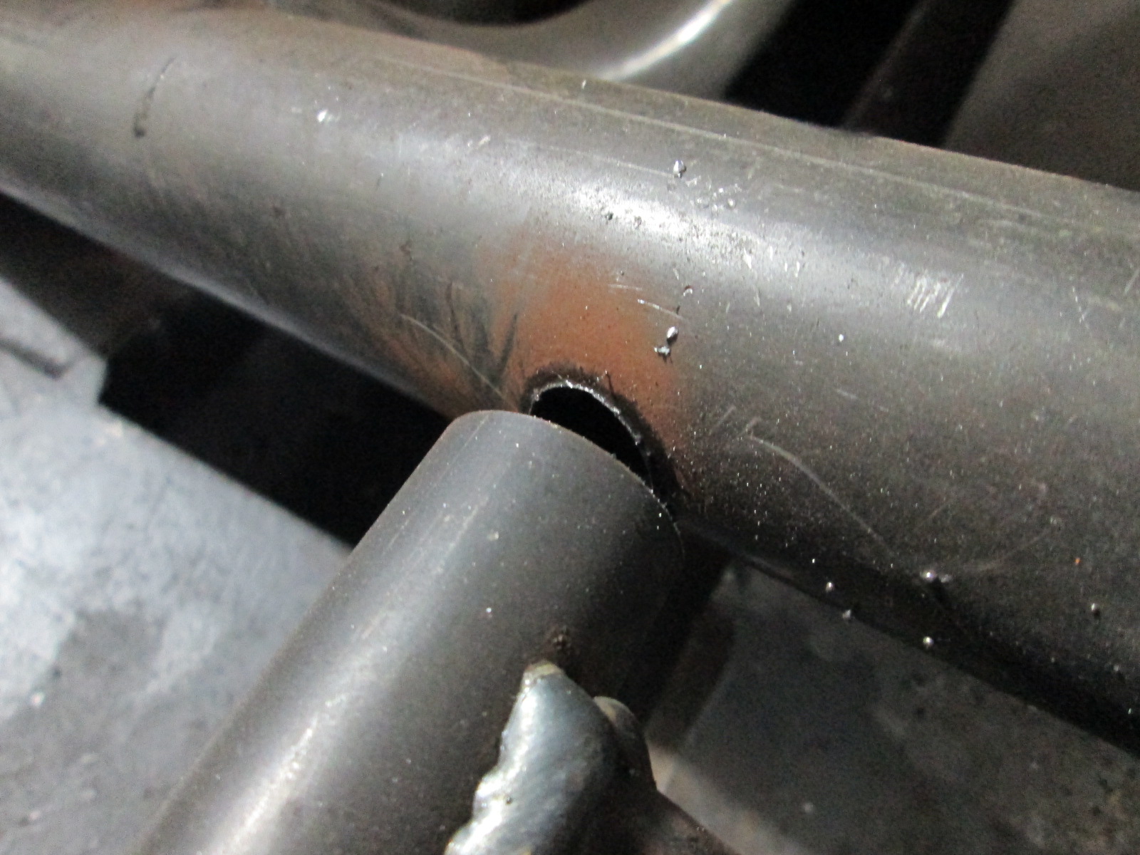
Started drilling out the trailing link hole. Stock is a M14 bolt, but I am going to upsize to a 16mm bolt due to the increased power. Right now the hole is 9/16" and I will work to enlarge it to 7/8 to fit the sleeve for the 16mm bolt. I have some 2" OD 1/8" wall tube and it will work great to overlay and reinforce this suspension attachment joint.
Also stumbled across this aftermarket traction control setup that is designed for racing and turbo applications with adjustable amounts of tire spin. It needs ABS sensors on all 4 wheels and is wired in between the ecm and injectors so it can cut individual injector signals to reduce power and limit wheel spin. I am working on late model upright swap front/rear which will use bearings with ABS sensors, so adding this controller wouldn't be too bad and is probably needed to help keep the Fiero facing the direction of travel. http://www.racetcs.com/
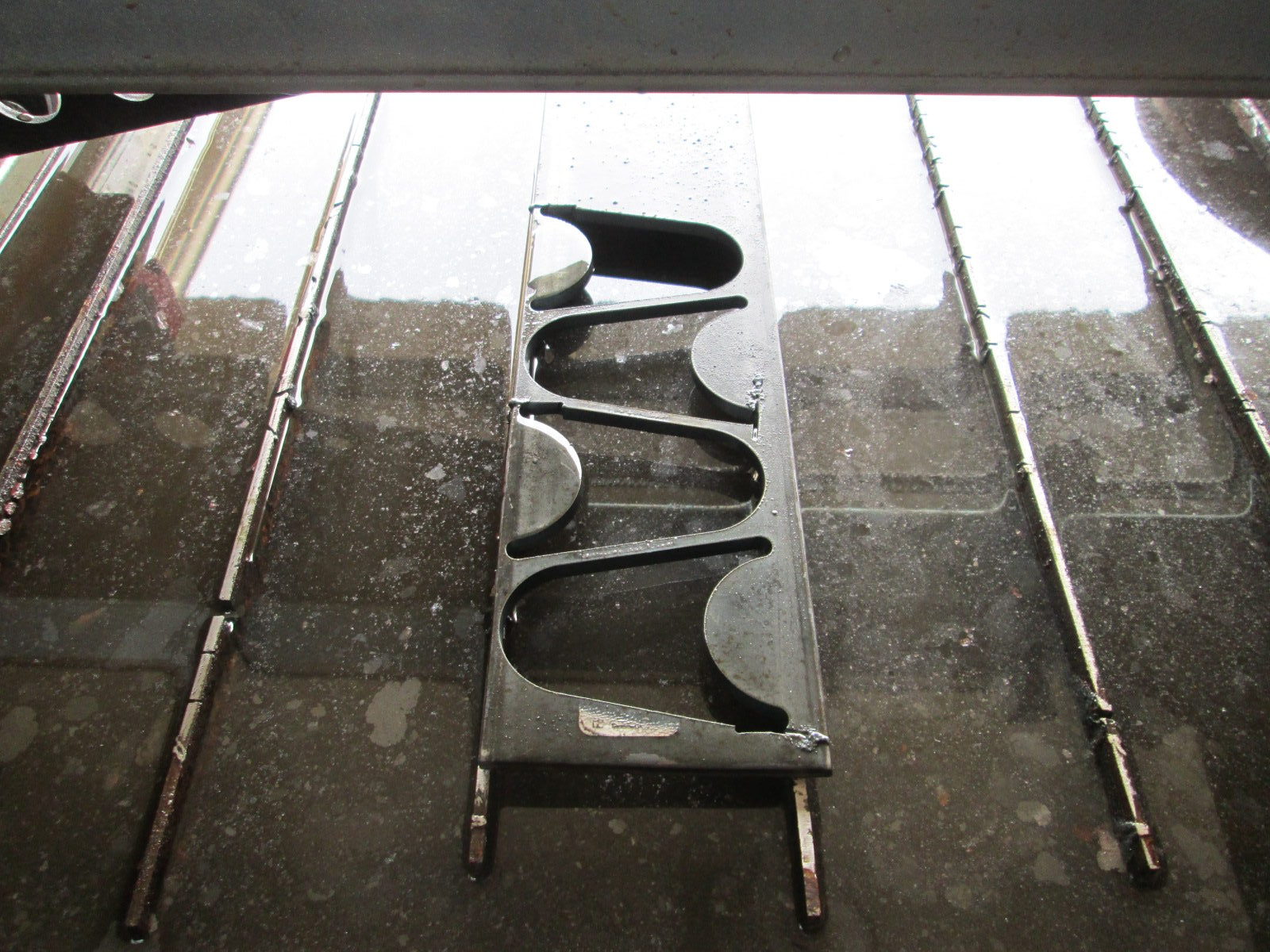
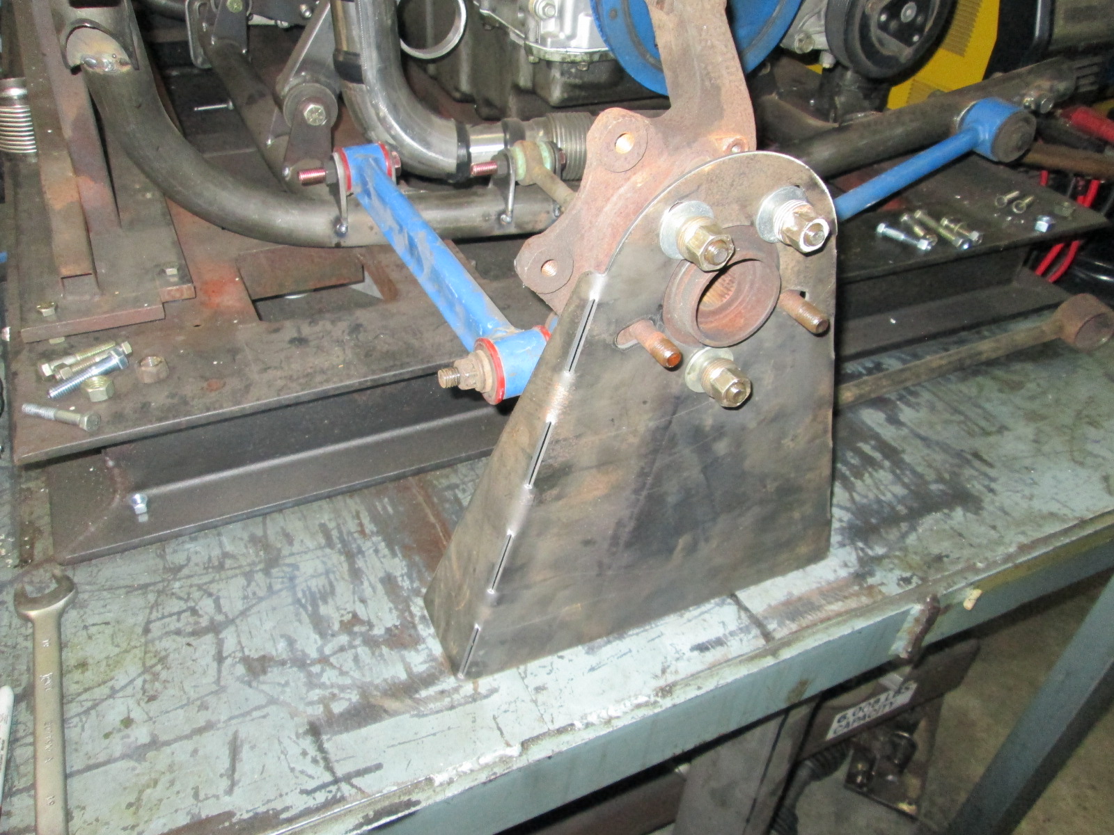
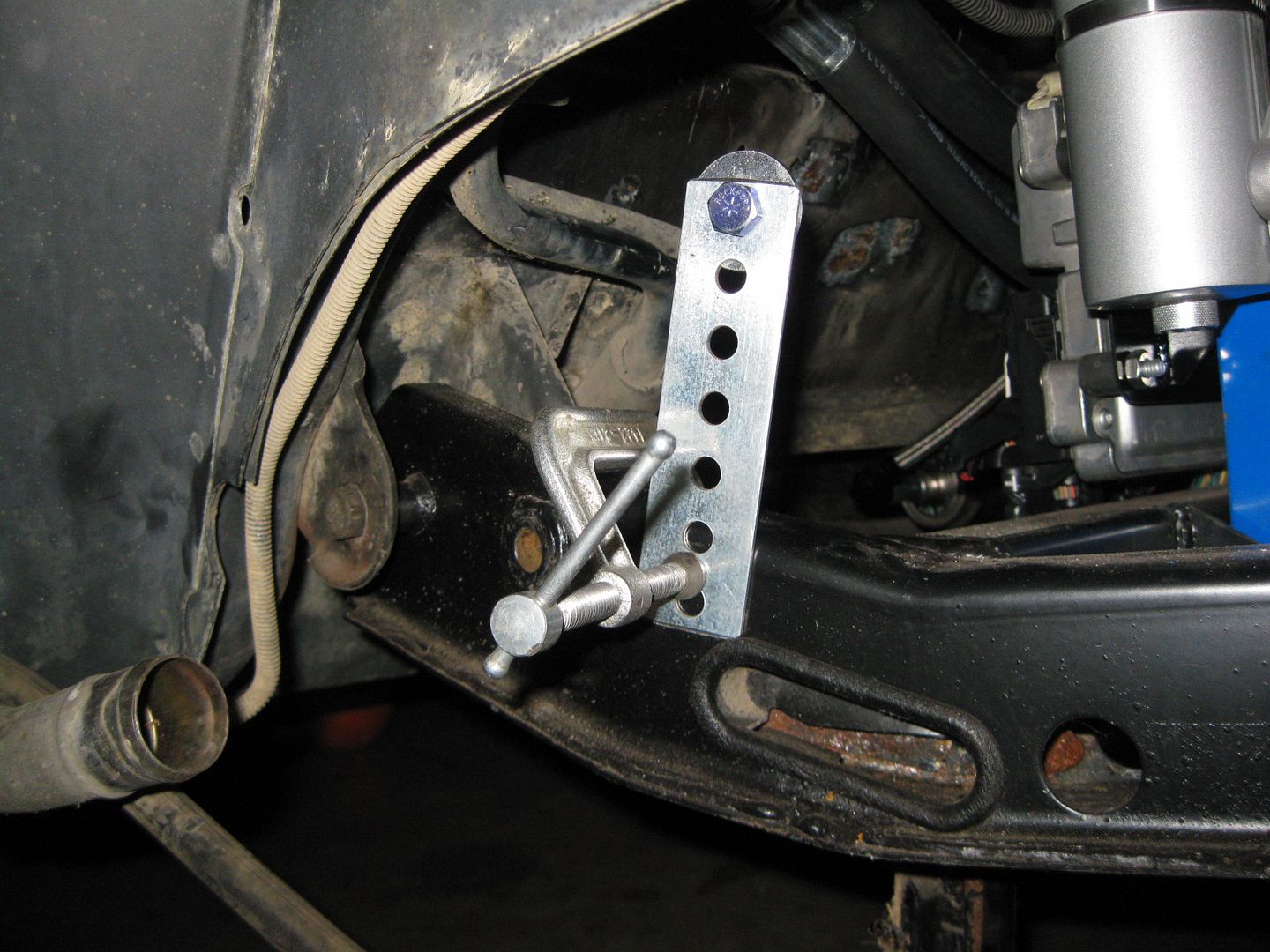
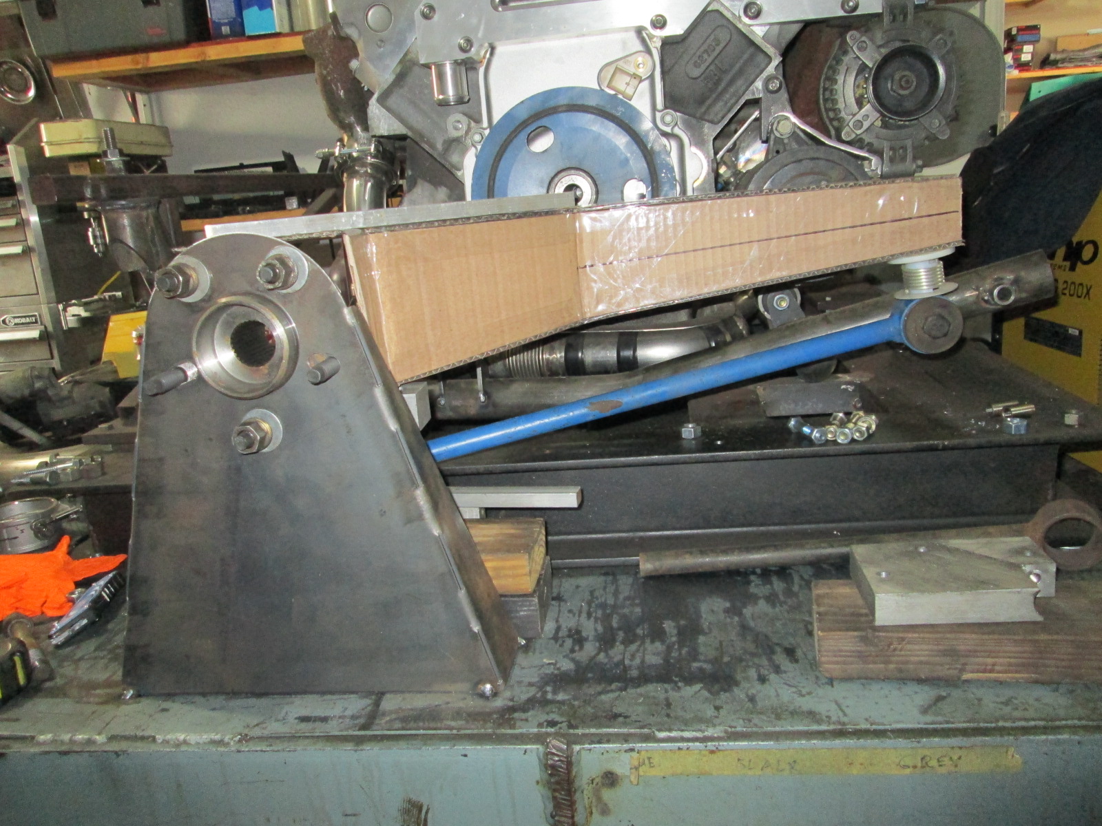
Here is a fun/functional part that will help with my suspension redesign that the CNC plasma table made easy.
It was designed to mount the wheel bearing/upright at the stock ride height and all the lug holes are slotted to allow any wheel bearing from a 5 x 100 to 5 x 4-3/4" to fit this stand. I cut some slits down the bend edges to make it easier to bend.
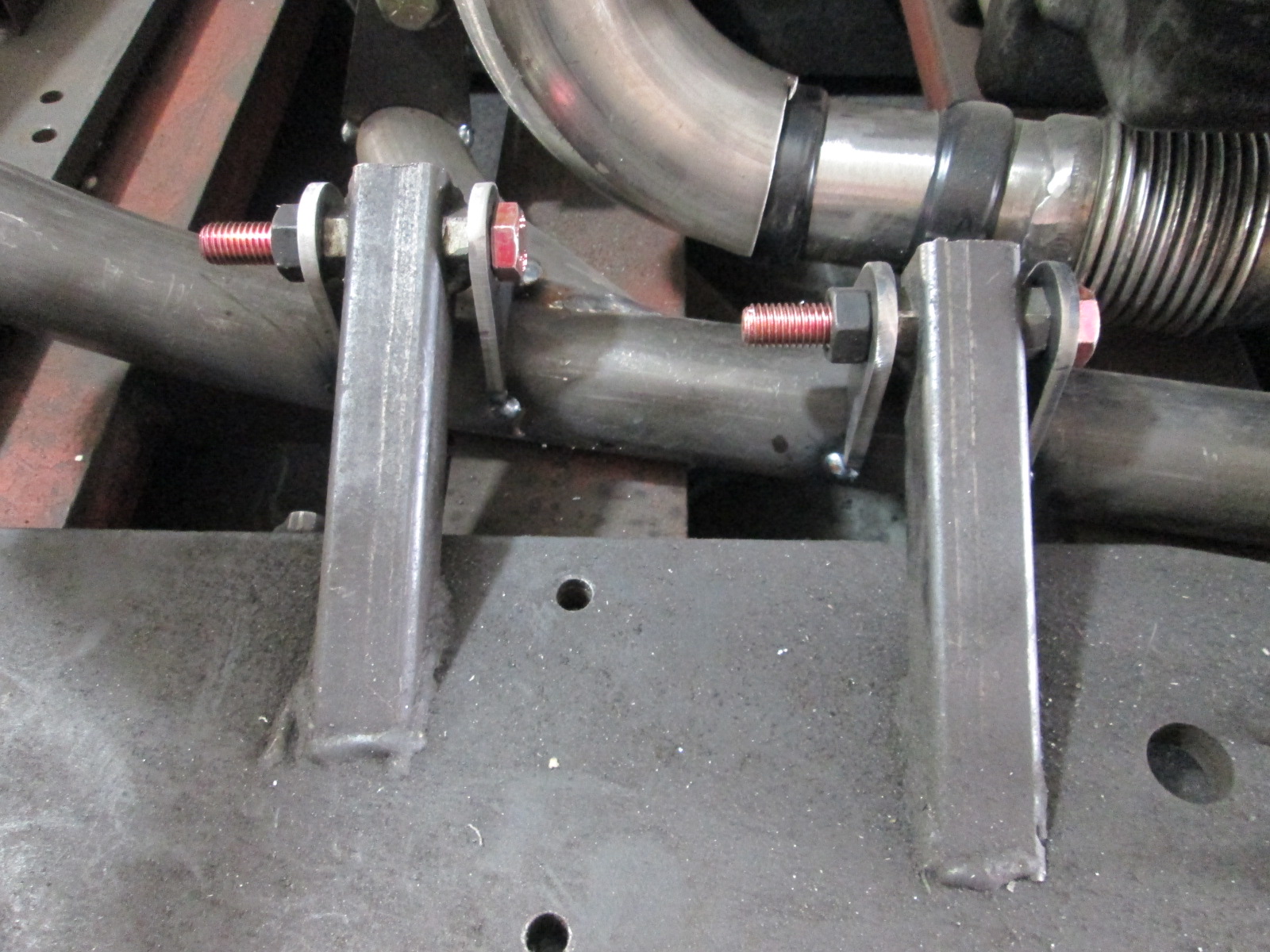
Now that I have the stock upright location identified (which is really the only reason I made the lateral link tabs and tacked them in place), I can start playing around with other uprights to replace the stock 88 one.
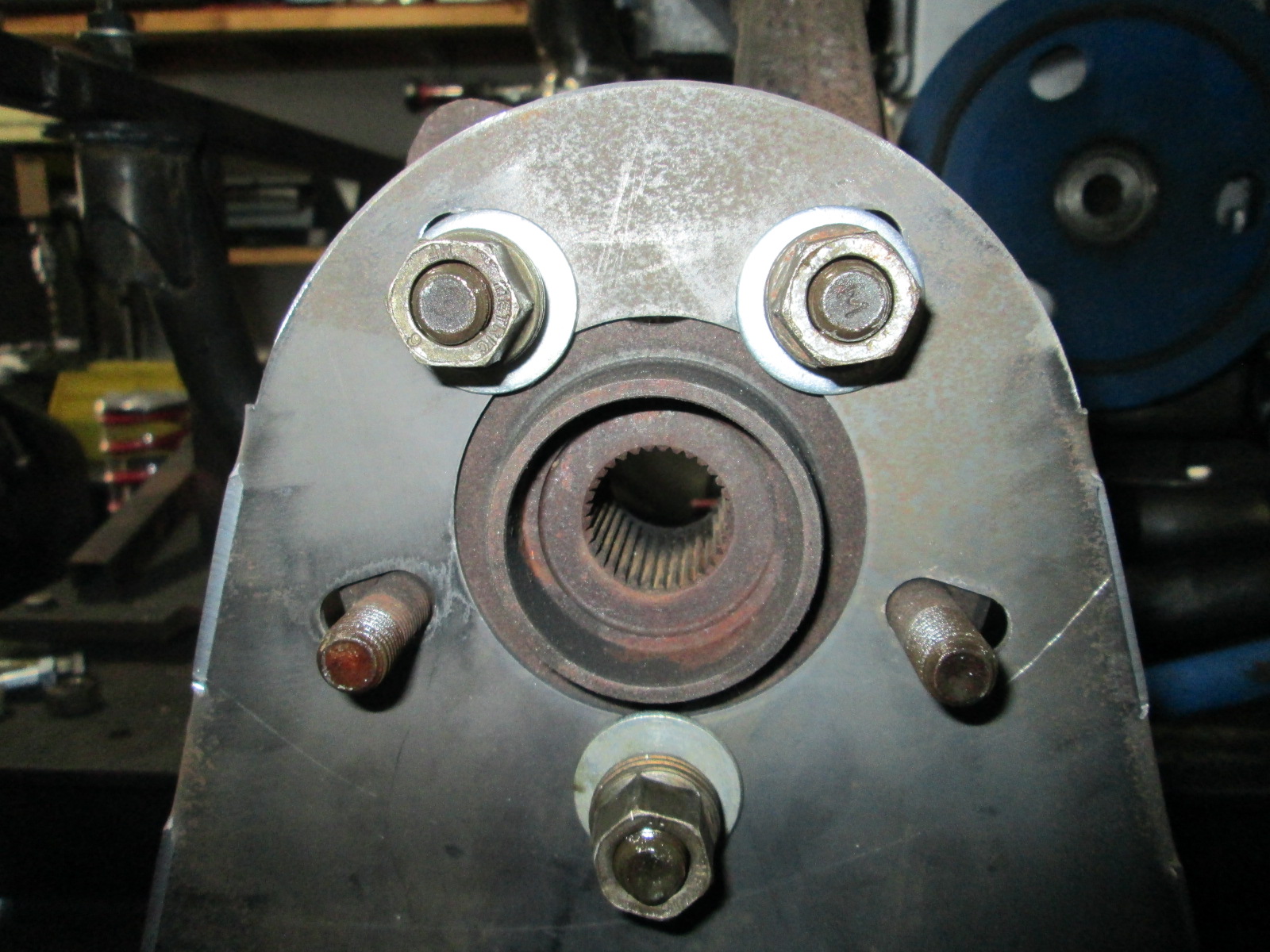
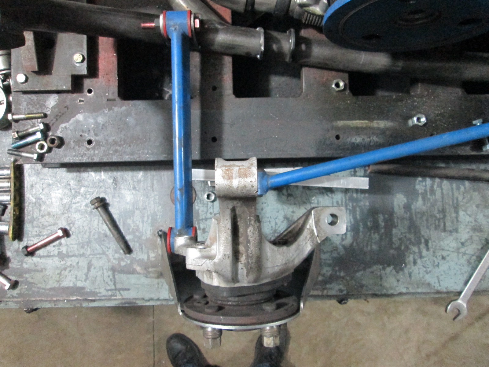
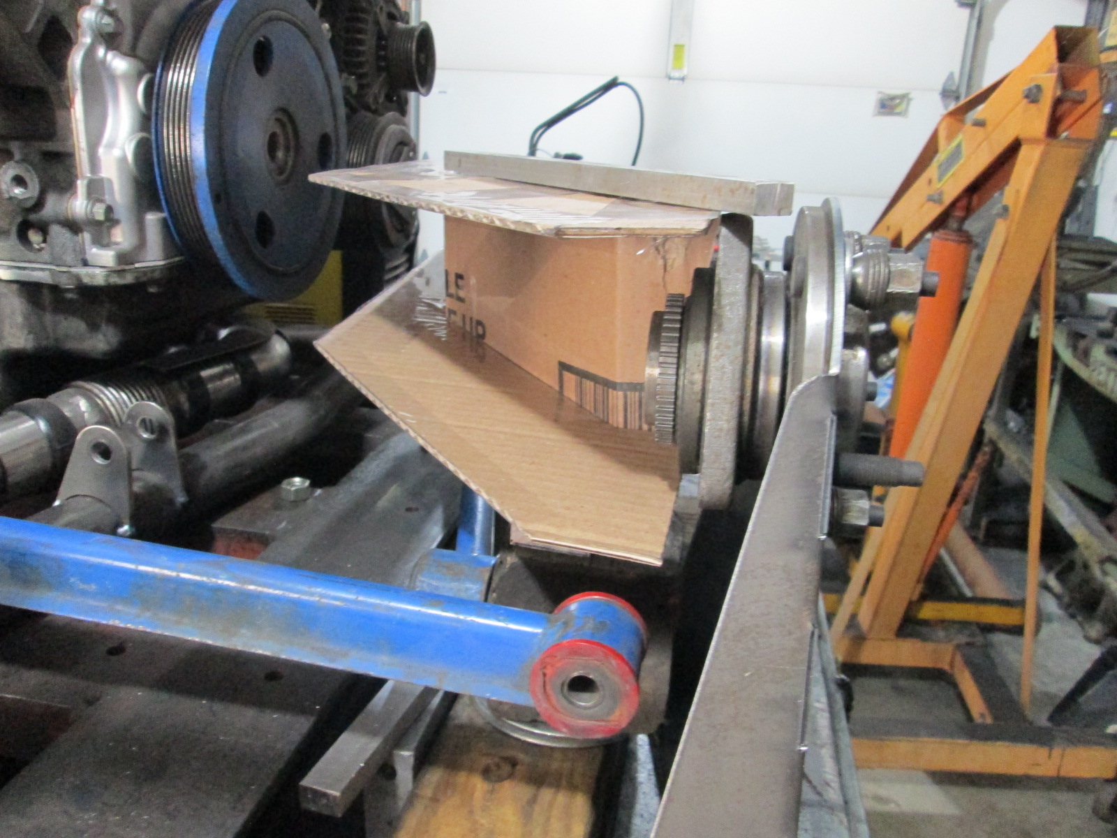
As I look for a different upright with a larger wheel bearing and spline for the CV, I have collected several when I was looking for options on the front. As part of this effort, I am trying to keep overall weight to a minimum as well, so that will also factor into my decisions. Here are the weights of the bare upright with the wheel bearing.
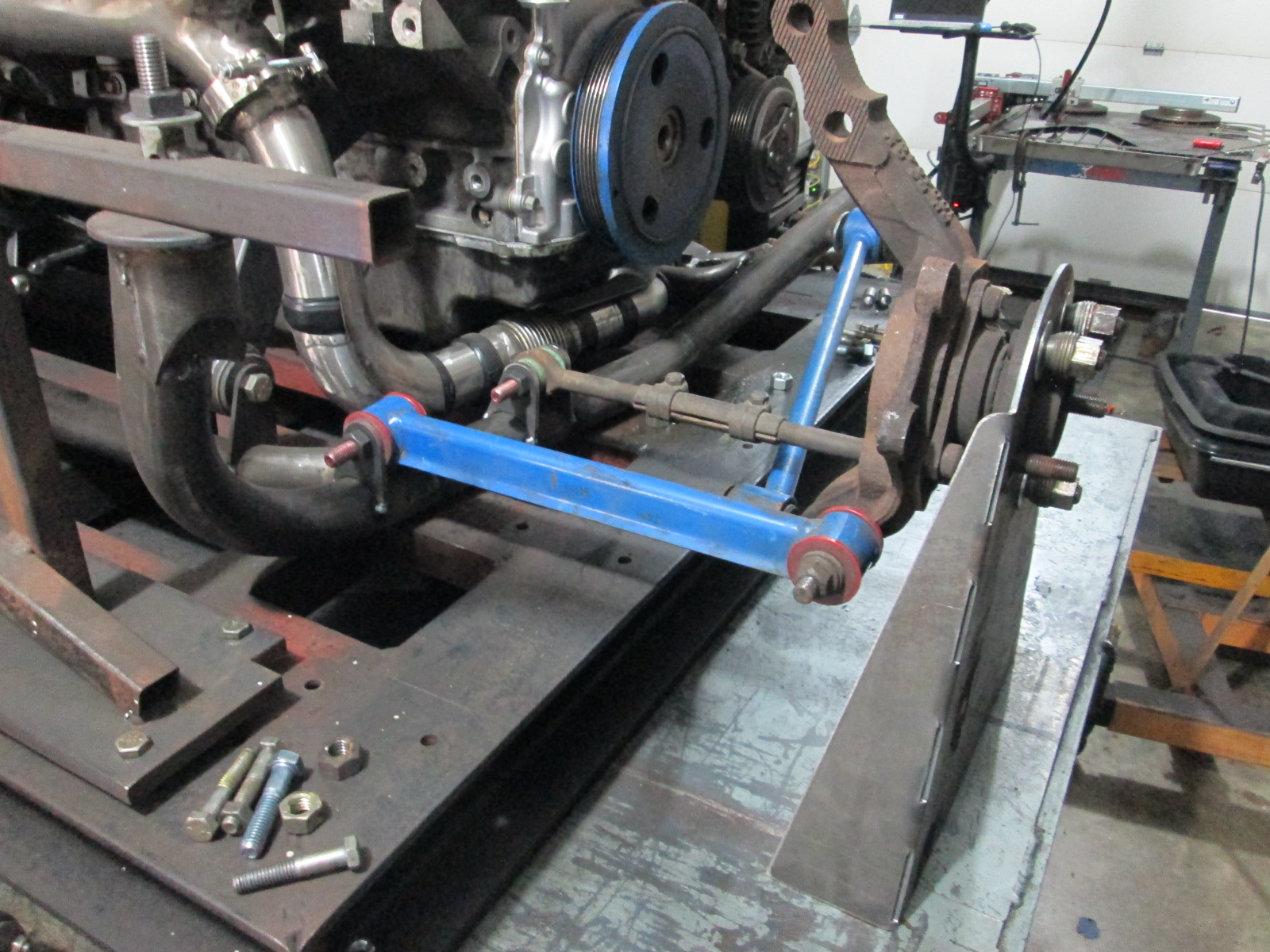
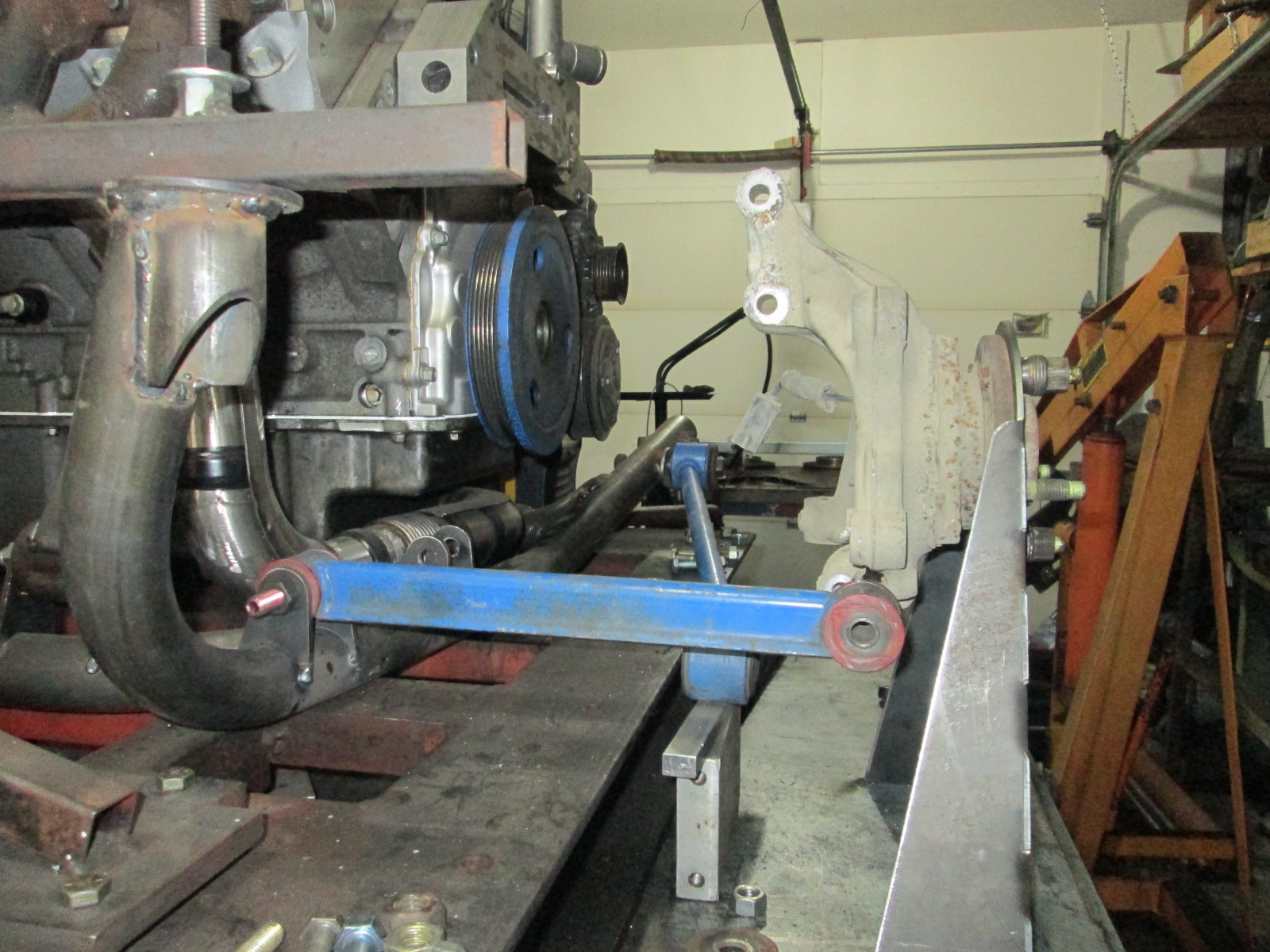
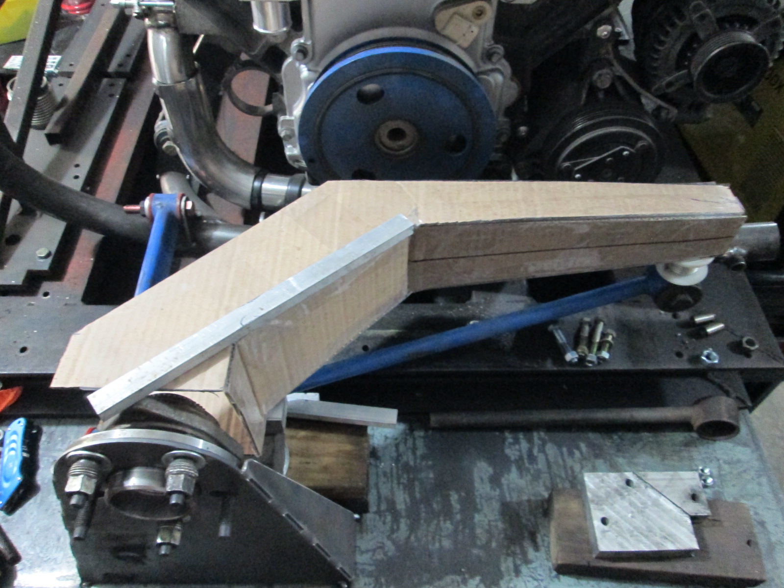
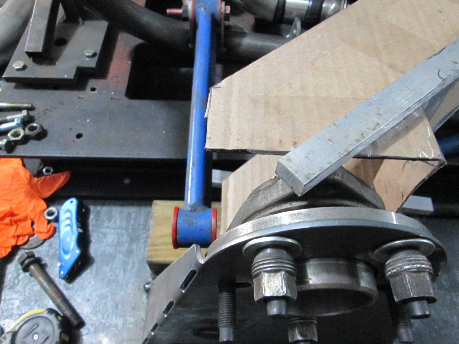
Let's see how the Cobalt SS fits around the stock 88 suspension trailing and rear lateral link. One item to take note of is since my car is lowered about 1 to 1 1/2", the upright will be 1 to 1.5" higher in the final application and I will keep the lateral link parallel.
I'm sure I'll understand it more if I re-read and study the pictures a few more times. Regardless of my inability to entirely grasp what you're testing or the parameters (besides weight), it's cool that you were able to fab up a "testing station"!
funny, I just drew this up last week, although it was going to be for a different purpose. I was going to brace it and put small wheels on the bottom so the weight of the car would rest on them , but still be allowed to settle, and use them to align the car with. I have since decided there were better ways to do that...
I'll be watching your knuckle ideas closely, I'm working on a clean sheet design, but if you can come up with something that will be less work, I might be tempted to but it...
------------------ "I am not what you so glibly call to be a civilized man. I have broken with society for reasons which I alone am able to appreciate. I am therefore not subject to it's stupid laws, and I ask you to never allude to them in my presence again."
Originally posted by Trinten: I'm sure I'll understand it more if I re-read and study the pictures a few more times. Regardless of my inability to entirely grasp what you're testing or the parameters (besides weight), it's cool that you were able to fab up a "testing station"!
quote
Originally posted by ericjon262: I'll be watching your knuckle ideas closely, I'm working on a clean sheet design, but if you can come up with something that will be less work, I might be tempted to but it...
The current thought process is inspired by the C3 tri-link design as well as Artworks interpretation. The C3s use a trailing arm assembly with the bearing/brakes and use 2 lateral links (1 at top, 1 at bottom). With the CNC plasma table, designing and making one of these for the fiero would not be overly difficult. The only thing I really don't like about this is the toe adjustment is done via the front attachment with shims.
This is where the artworks interpretation comes it. It is the same basic idea, but uses a stock knuckle attached to the arm structure. The two separate parts (depending on how they were designed) would allow toe control at the knuckle vs. the front attachment.
Ideally, I want to use the stock front trailing link attachment point to the cradle and the rear lateral link location with everything setup for a 1" lower stance. The upper link will likely require a hole in the lower strut tower /frame rail area.
Where's that photo from? Is there a build thread for that someplace? I've been wondering if designing something like that was worth the effort... interesting to see that someone else is thinking along those lines.
A single trailing arm doesn't give you a lot of leeway to set up the anti-squat, but a 5 link per side suspension does...
Originally posted by Will: I've been wondering if designing something like that was worth the effort... interesting to see that someone else is thinking along those lines.
A single trailing arm doesn't give you a lot of leeway to set up the anti-squat
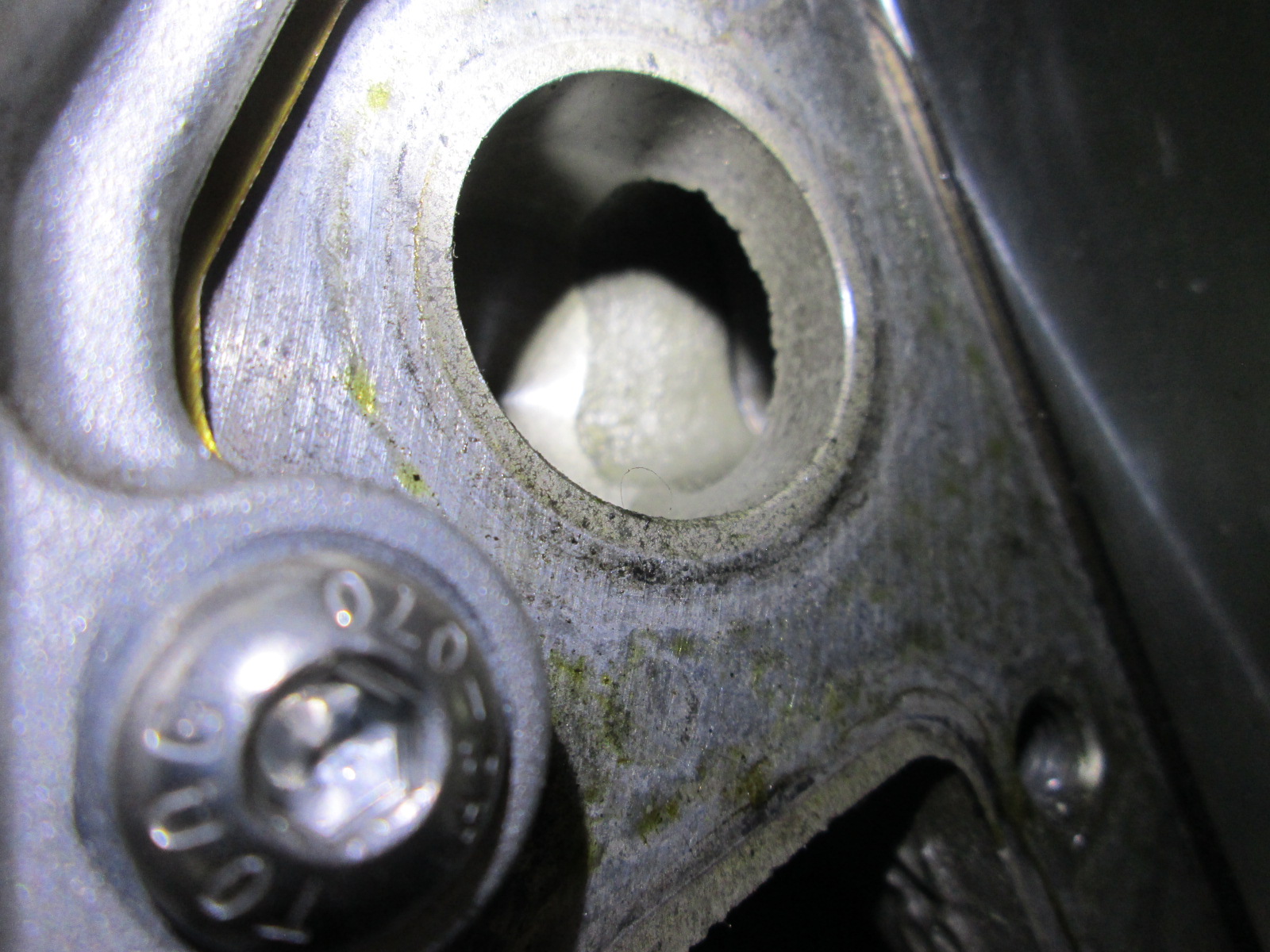
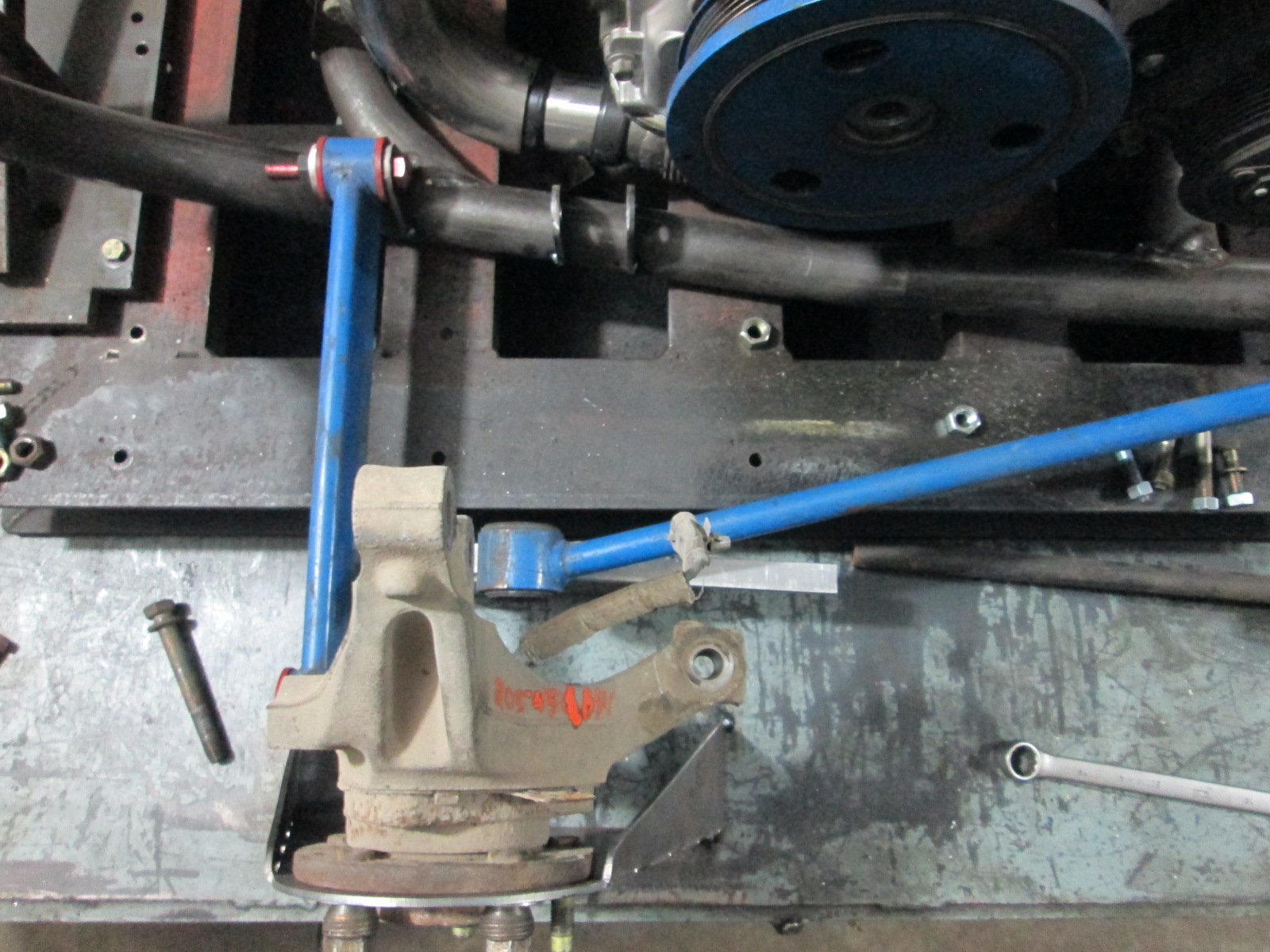
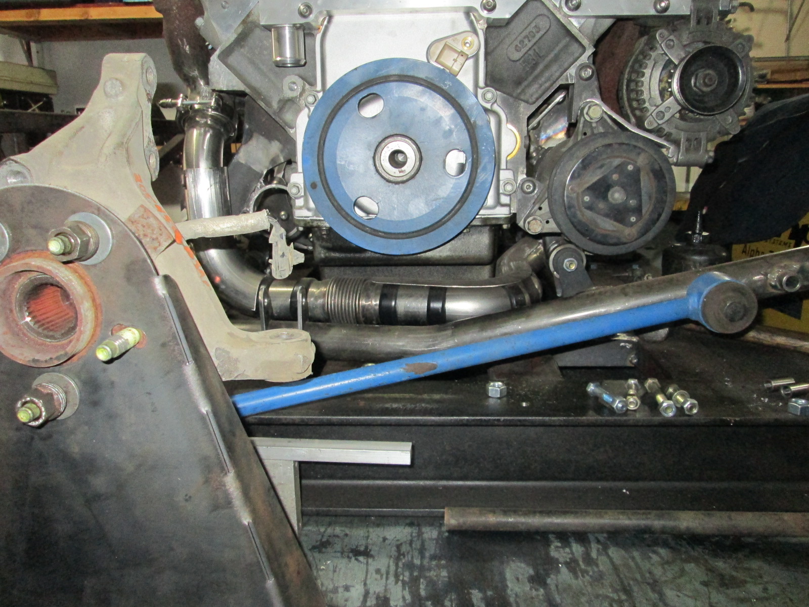
The wheel bearing is about 2" above the front trailing link mount at stock ride height, so using just it would result in negative anti-squat. There is some available room to raise the front trailing link mount with a bolt-on/weld-on bracket between the front cradle bolts and the front trailing link bolt. If I can get it to neutral anti-squat I would call that as victory.
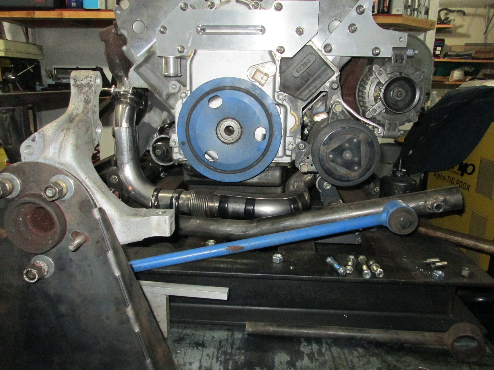
Here is an old picture showing the space in this area.
There is a little room above the front trailing link mount to raise that location with a bolt-on/weld-on bracket. Not sure I could get into anti-squat, but I would be happy with neutral. My main goals for this rabbit hole is stronger wheels bearings and CVs, better camber curve, and elimination of the stock strut all while using some of the stock suspension locations on the cradle. With the proper design, inboard rear tire clearance could be optimized so I can tuck an even wider wheel/tire combo than the current 9.5/285 combo. Whe knows, it might be able to make it all lighter than the current suspension setup.
The more I ponder the custom trailing arm or the arm/knuckle combo, I am leaning further and further toward the custom trailing arm. I think I could cut out nearly all the needed parts with the appropriate geometry on my plasma table, bend and weld them up. This would give me more freedom with the location of the two lateral links (1 upper and 1 lower) relative to the frame rail/strut tower area. I am traveling next week and will have some hotel evenings I can devote to some autoCAD exploration of the concept and how I would build it.
[This message has been edited by fieroguru (edited 03-06-2021).]
as much as I like the three link design on the 88's, it seems the auto makes w/ independent rear ends prefer the rear spindle set up like the 84-87 design. The Corvette, Mustang, Camaro and GTO all had a design like the early fieros. I know the issues w/ bump steer but those cars seem to have figured it out. I know you're looking at using the newer spindle from the pics above, but again, those are all from FWD cars so you'd still have to tie off the steering arm to the frame or lower control arm. Unless your talking about fab'ing up something like the vette 3Gen trailing arm? It seems the forward trailing arm is what gets in the way of a large tire/rim. Looking forward to your design, maybe its something that can be modified for those of us w/ stock cradle setups.
Since I picked up this 87 GT i've started looking into using modern FWD spindles w/ bigger brakes instead of the older 84-87 stuff. Once I saw your photos of the newer spindles w/ your 88 setup I started to think maybe its poss to use the newer spindles and fab up a lower control arm that would bolt to the stock 88 mounting points on the cradle, offer a single lower ball joint mount (for the FWD spindle) and then figure out how to use the old "bump steer" design from Ryane/Held MS to create a new rear spindle set up. The top of the spindle would need to be modified to allow the strut to angle the same as the Fiero, but It seems that a bracket with the bottom hole on the spindle being the same and the top being modified for the Fiero angle could work.
[This message has been edited by qwikgta (edited 03-07-2021).]
also, thinking about a way to convert the single balljoint lower to the dual control arms on the 88. Poss using some square tube with flat plate welded to the ends. Inside the ends before welding them on the tube you could weld on a large nut. Then after welding the end 'caps" on you could just use a bolt to hold the heim ends on, providing the ability to travel up/down.
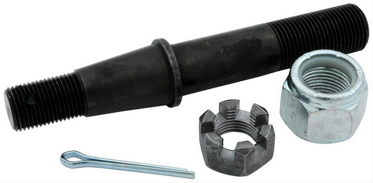
In the middle of the square tube you could install a balljoint stud, like this
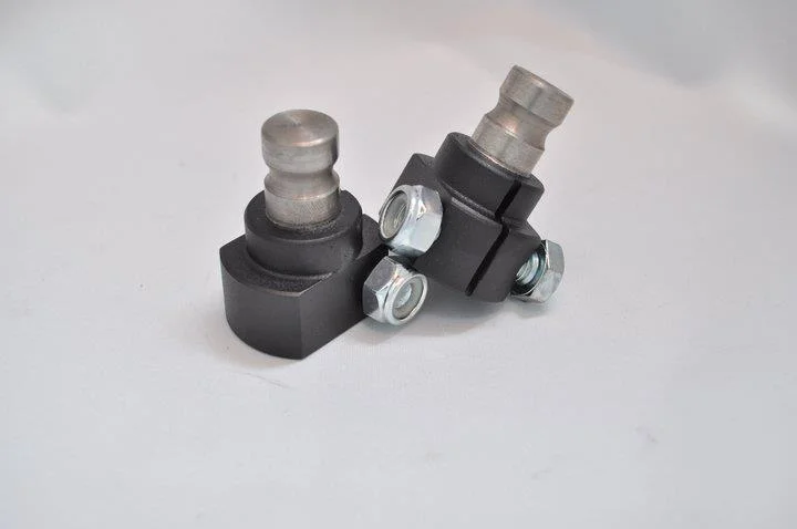
or more like this one. Maybe it could be milled out of steel and welded onto the square tube.
and then connect the spindle to it. It would still move in/out, so it would need to have the steering arm connected to something that would allow for toe in/toe out similar to the ryanne/held setup. Doing this would remove the forward lateral bar and allow a wider tire.
Rob
[This message has been edited by qwikgta (edited 03-06-2021).]
Originally posted by qwikgta: as much as I like the three link design on the 88's, it seems the auto makes w/ independent rear ends prefer the rear spindle set up like the 84-87 design.
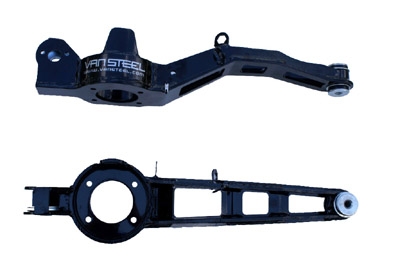
As with anything, there are hundreds of possible solutions. Where things differ are the constraints people put on their solution. Since I am an 88 only guy, I want my solution to use as many stock 88 suspension pickup points on the cradle as possible.
Here is a very crude visual of what I am looking at doing. In its current shape, there is 1" more clearance to the inside lip of my 9.5" wheel/tire. Still a lot more refinement to the design is needed as well as some mockups in the chassis to verify clearance to the frame rail, but this is a good place to start.
Originally posted by qwikgta: or more like this one. Maybe it could be milled out of steel and welded onto the square tube.
and then connect the spindle to it. It would still move in/out, so it would need to have the steering arm connected to something that would allow for toe in/toe out similar to the ryanne/held setup. Doing this would remove the forward lateral bar and allow a wider tire.
That looks like Honda, BMW E36/E46 and 1G DSM rear geometry, although only Honda used links that short.
Edit: Oh. That's a Jalapeno kit installation... That's why I never saw it.
quote
Originally posted by fieroguru:
The wheel bearing is about 2" above the front trailing link mount at stock ride height, so using just it would result in negative anti-squat. There is some available room to raise the front trailing link mount with a bolt-on/weld-on bracket between the front cradle bolts and the front trailing link bolt. If I can get it to neutral anti-squat I would call that as victory.
I've looked at the same area for modifications to the trailing link mount.
The anti-squat for a trailing link strut is calc'd differently than for a trailing arm suspension, so beware.
[This message has been edited by Will (edited 03-08-2021).]