Haven't had much free time lately, but some more parts came in and did complete a few small projects for the swap.
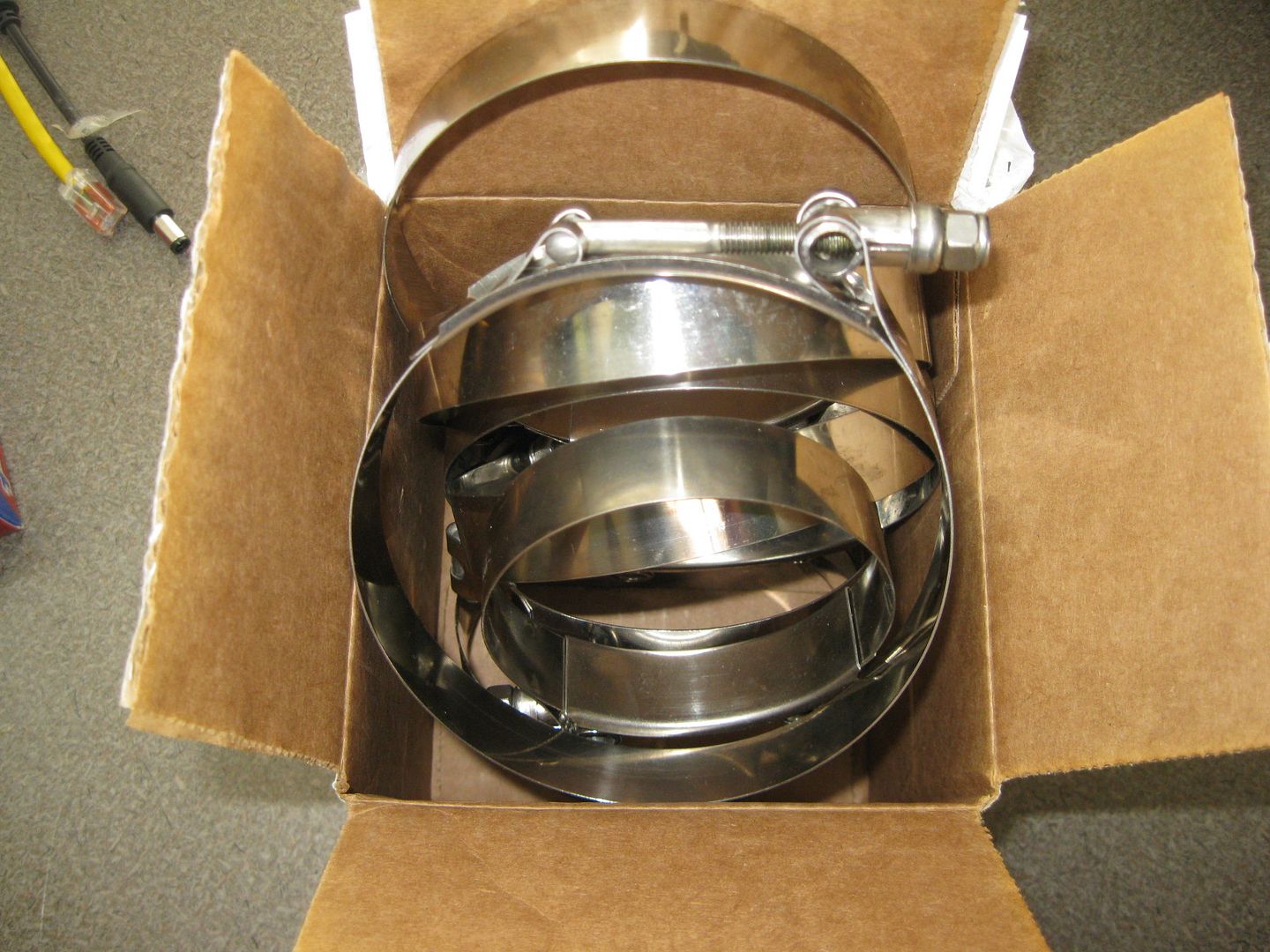
http://www.siliconeintakes.com sent me the TB to MAF reducer, a 4" elbow for the filter, and several stainless t bar clamps.
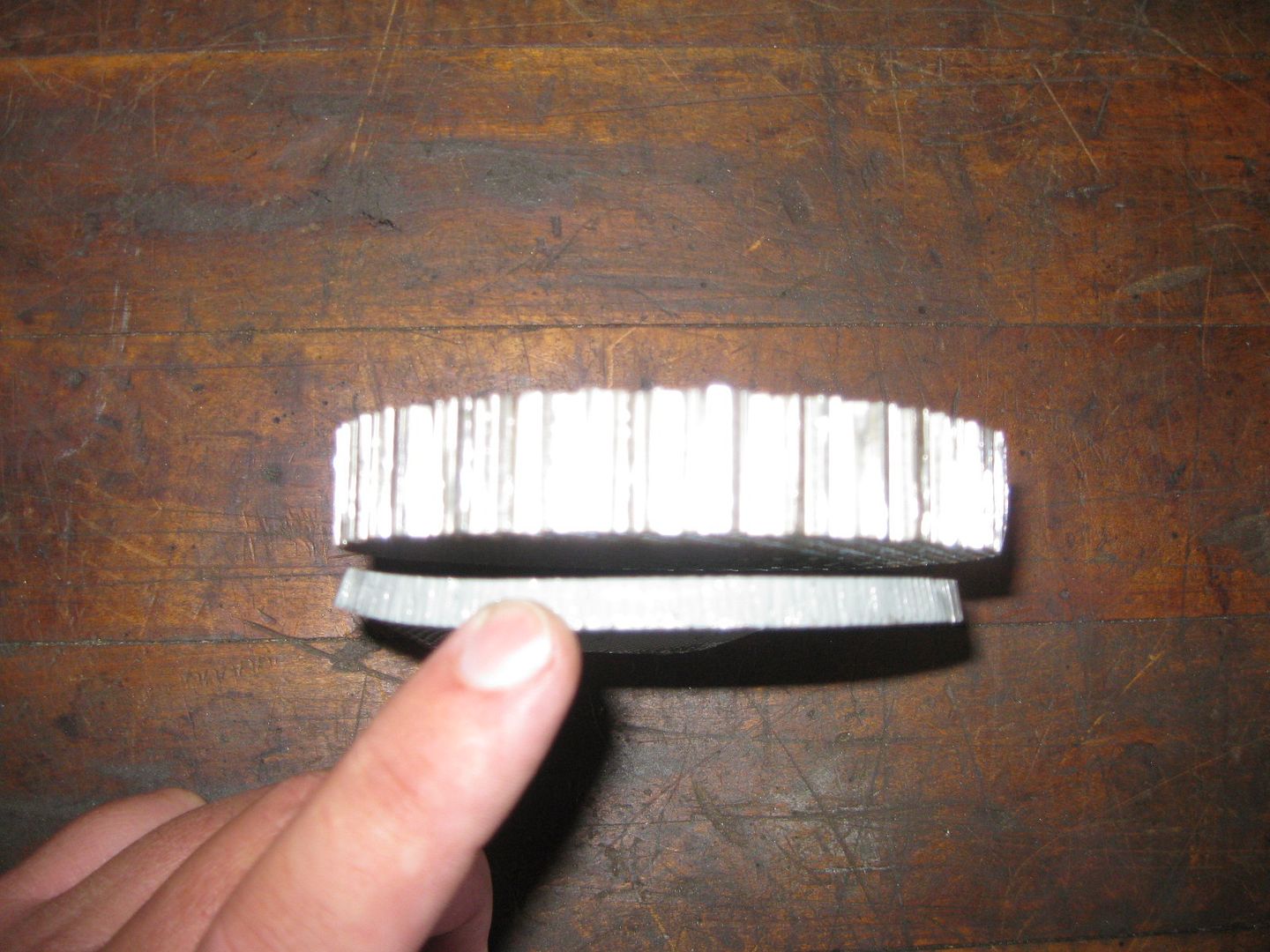
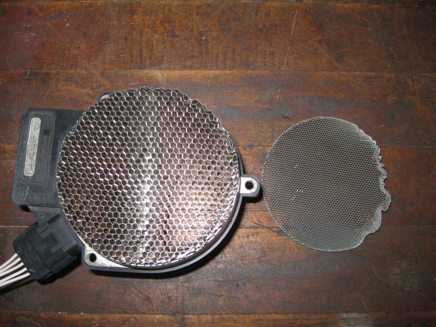
http://www.saxonpc.com/airflow-products.html supplied a new mesh screen for the MAF. It is has larger holes for more flow, but is longer to help align the air stream before the MAF.
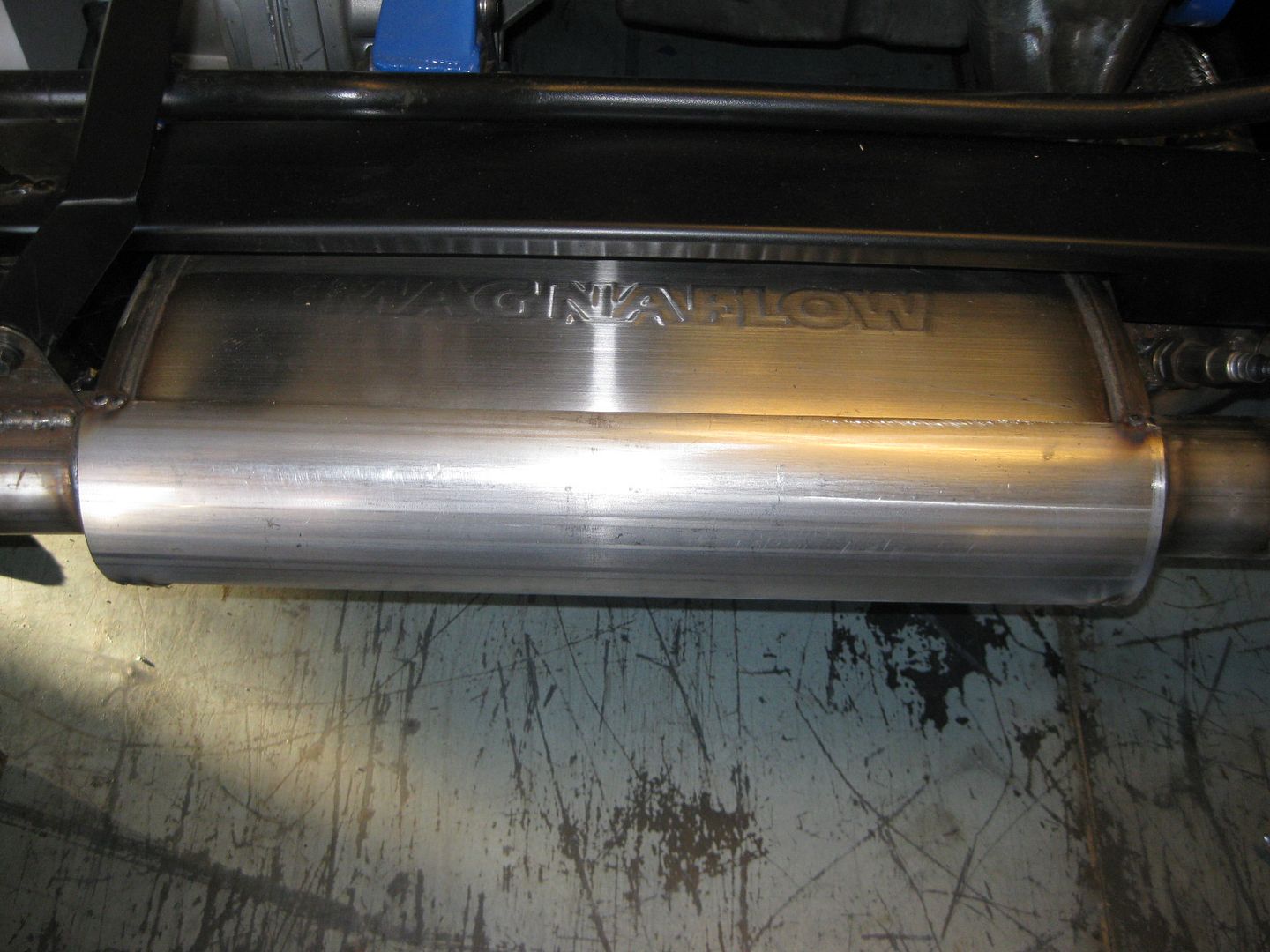
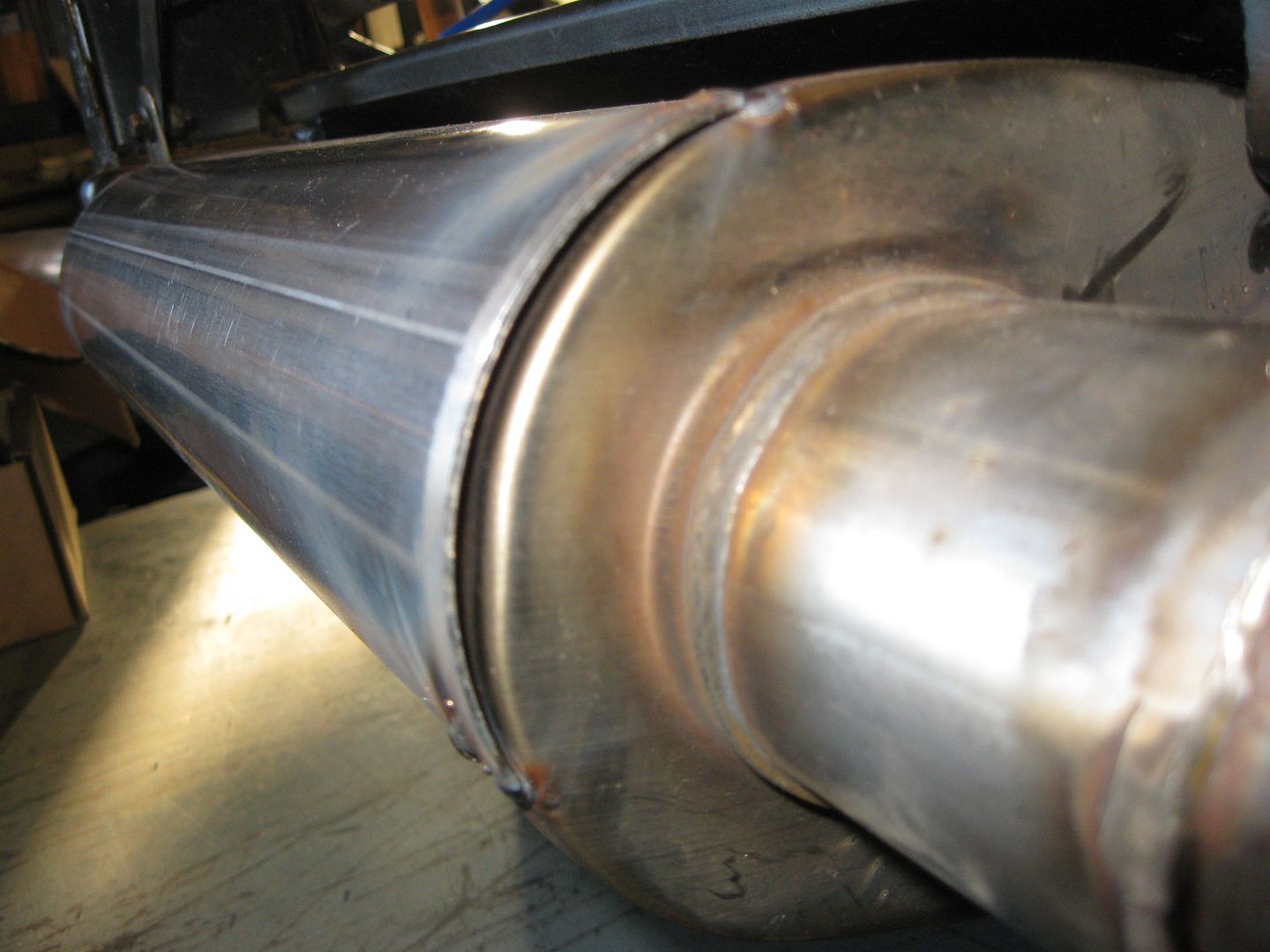
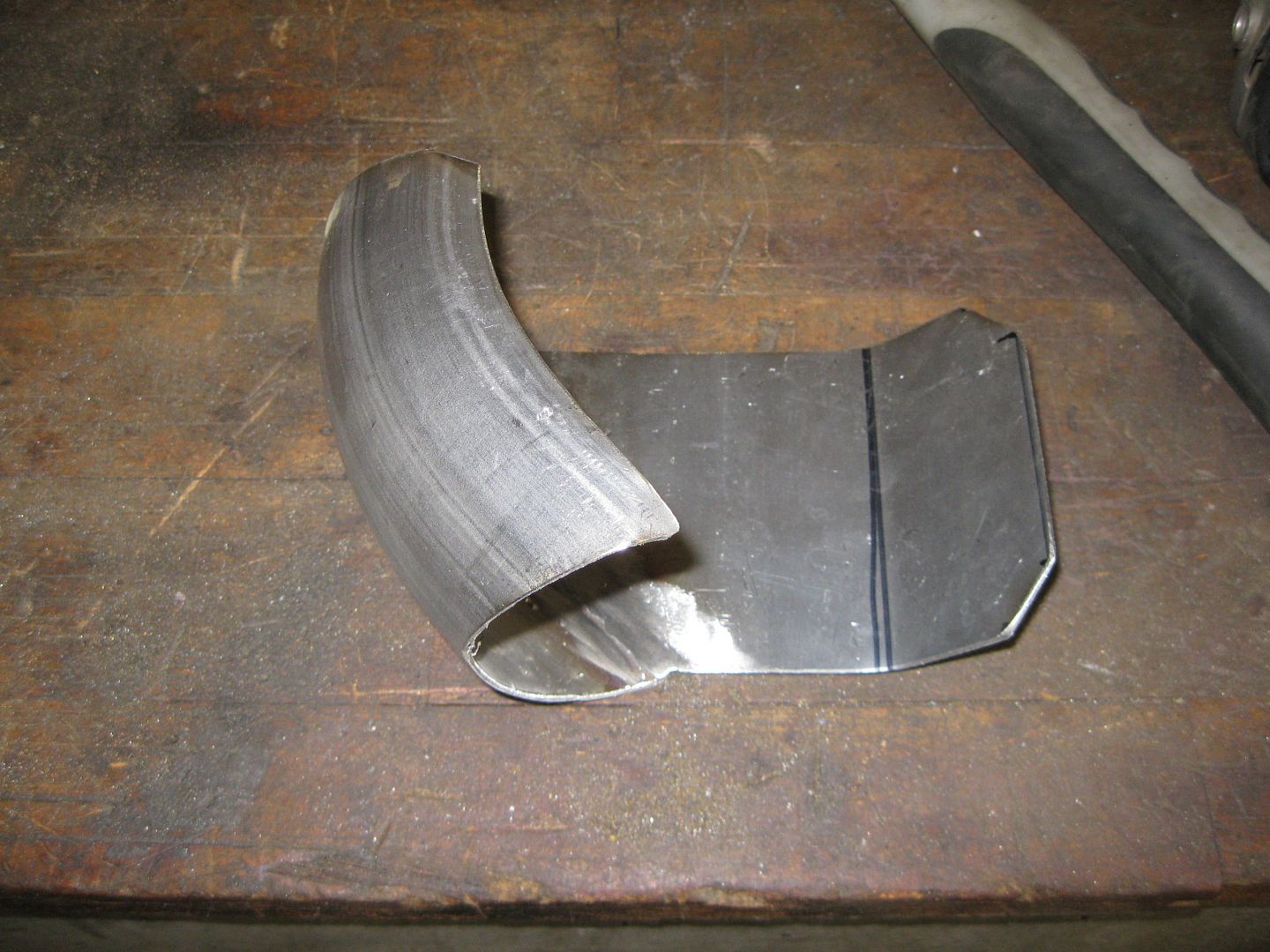
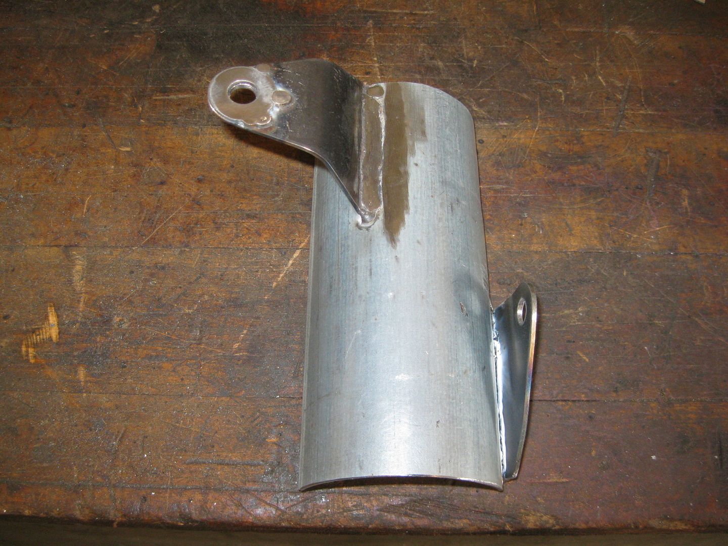
The 4" diameter stainless exhaust tube arrived a couple weeks back, so I cut it to the needed shape for the heat shield between the muffler and the trunk and welded it to the muffler:
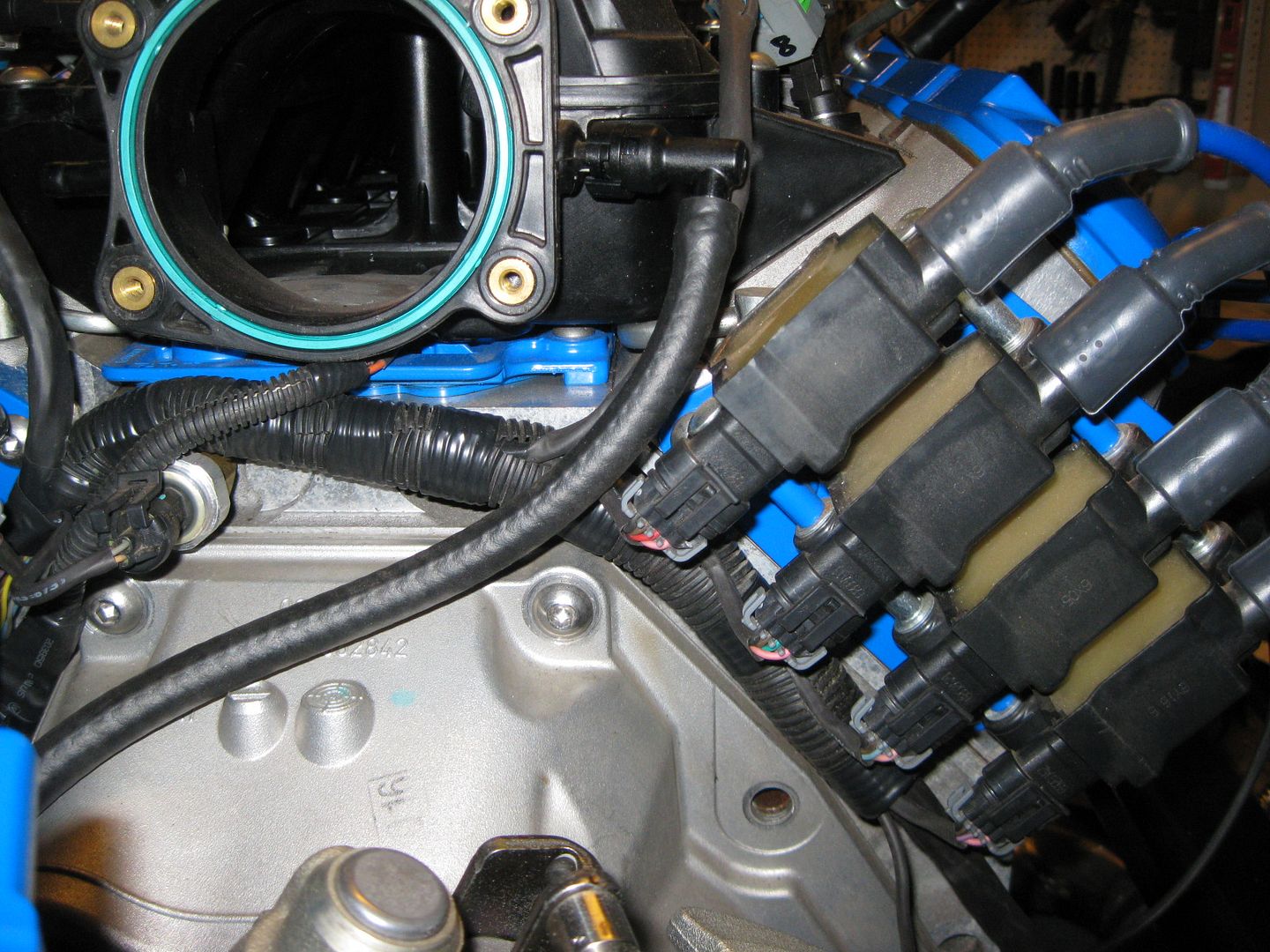
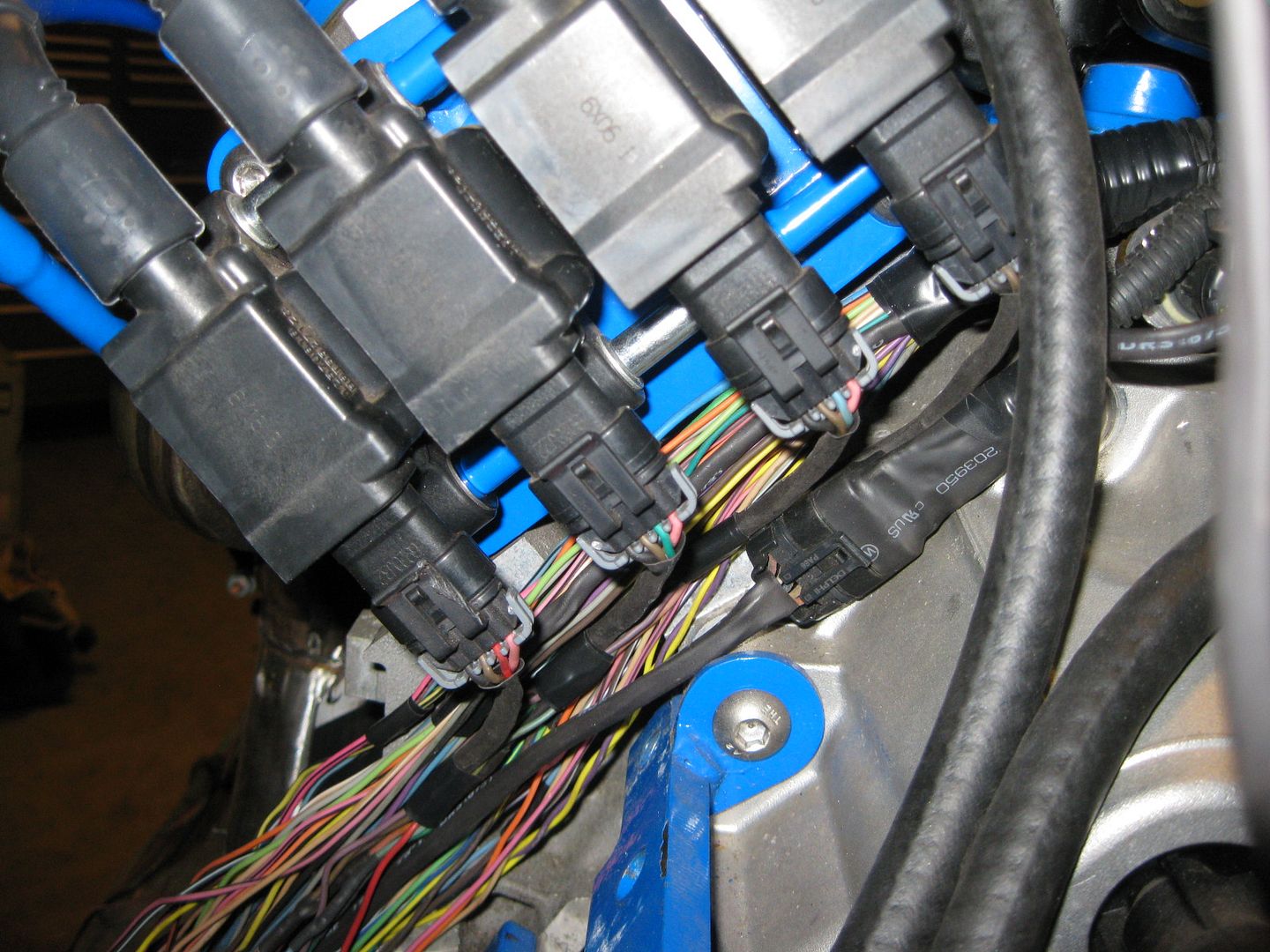
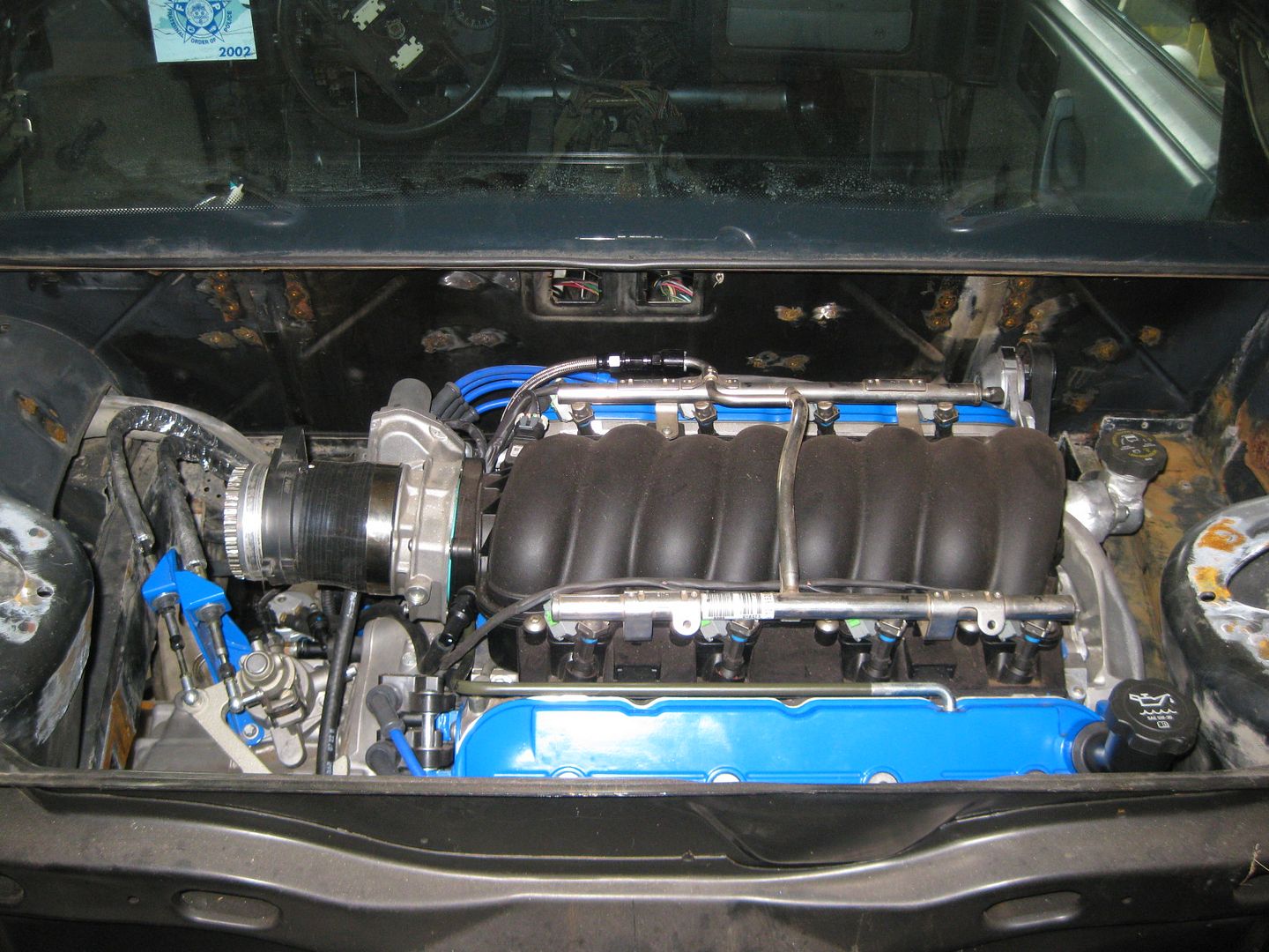
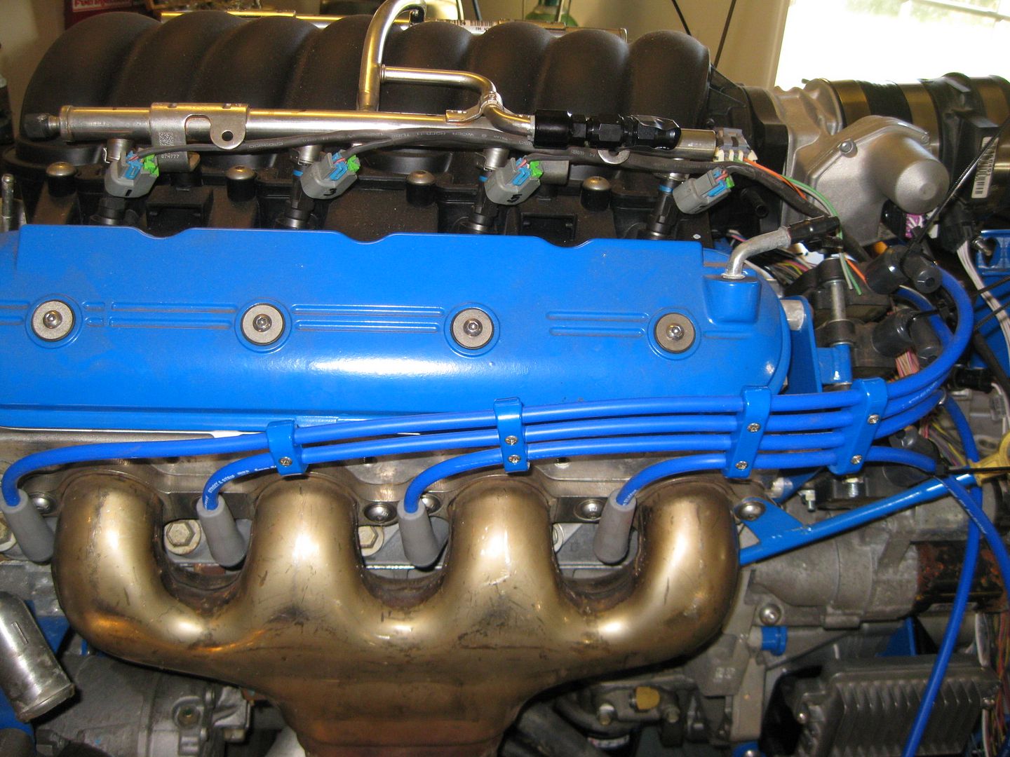
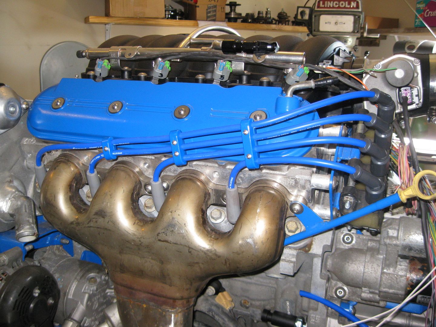
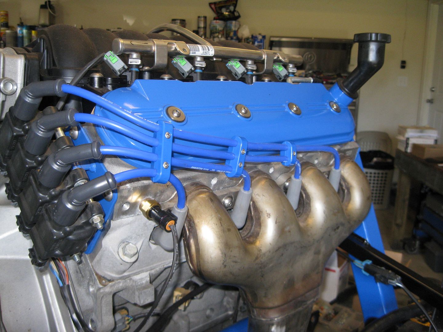
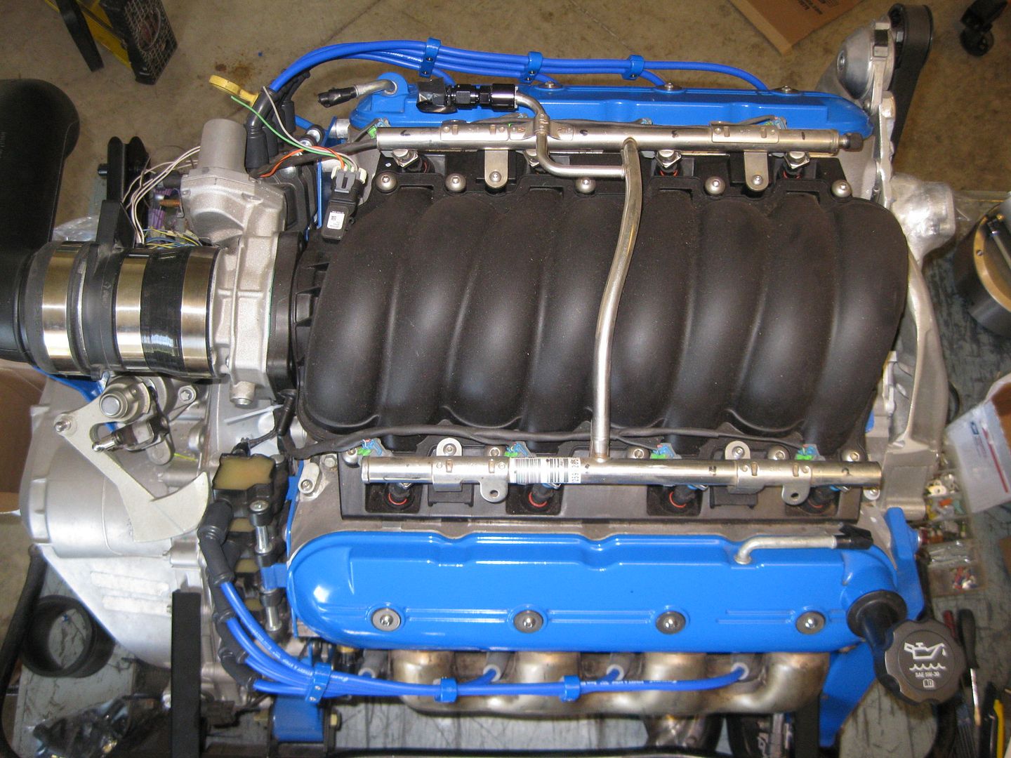
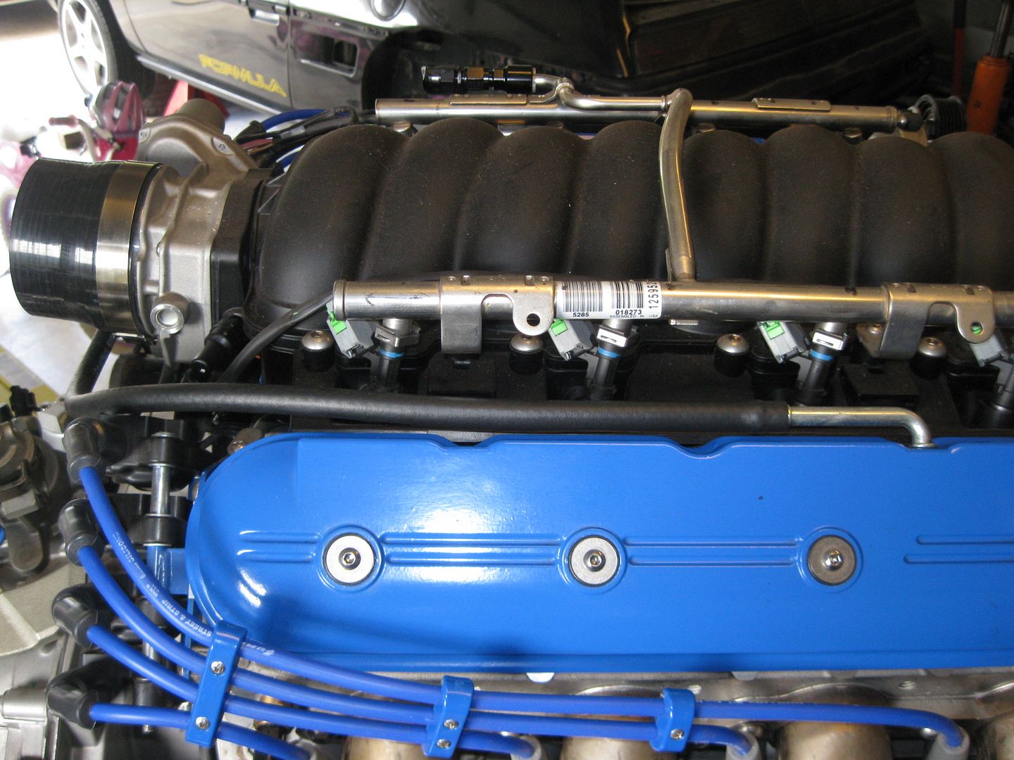
Then I started to play around with the routing of the plug wires. I mocked each side up slightly different as I determine which one I like looking at. Here is the front side. The wires are stacked on top of each other and remain stacked while they meet up with the coils:
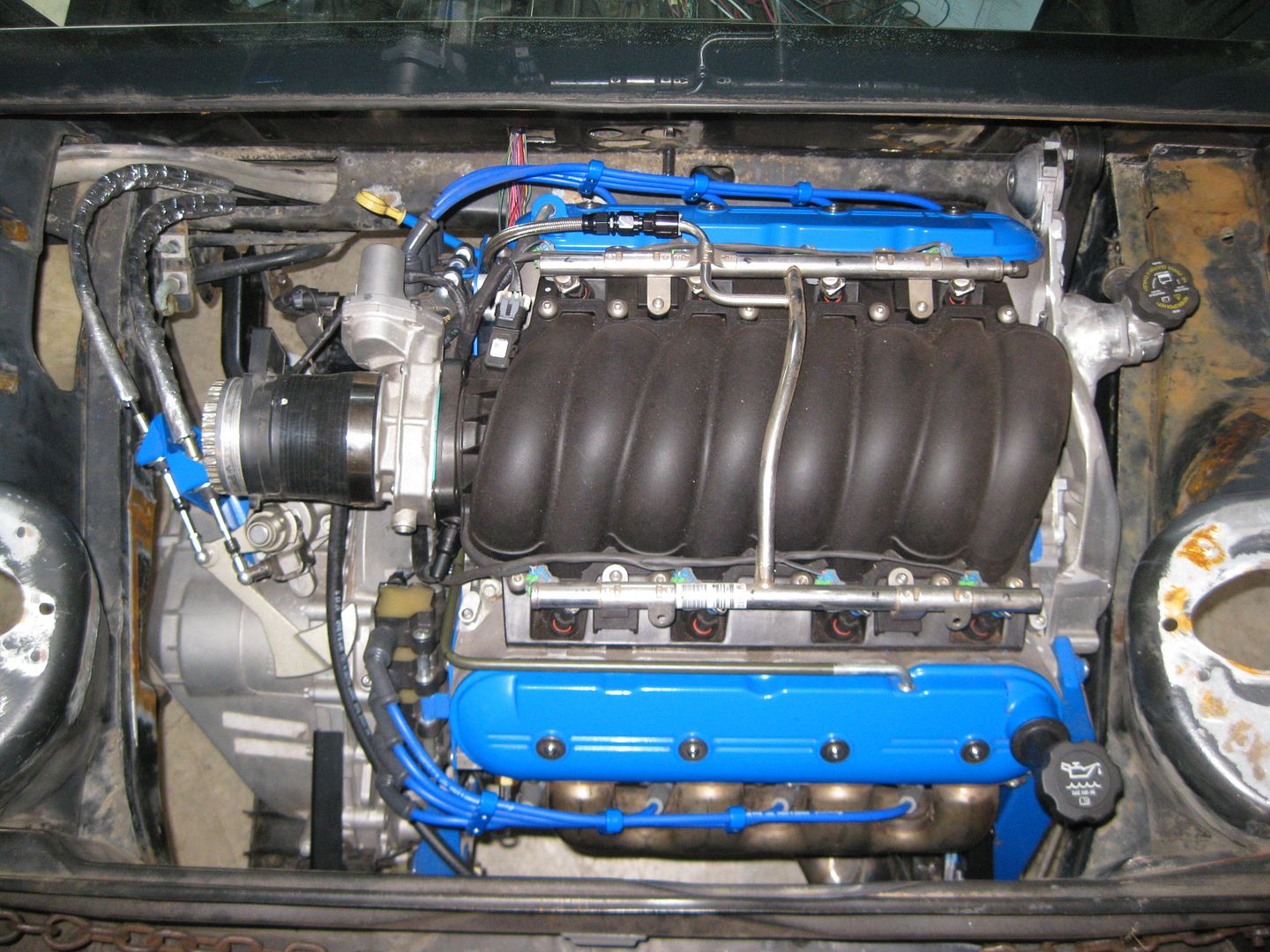
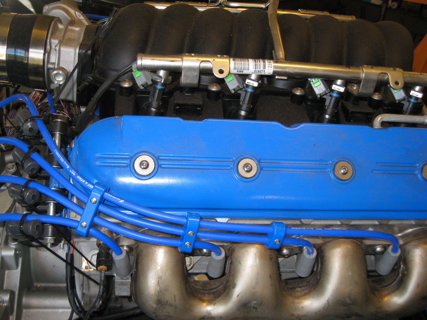
The rear side is slightly different in that the wires pretty much lay over as they turn to the coils. This setup ever so slightly covers the corner of the valve cover.
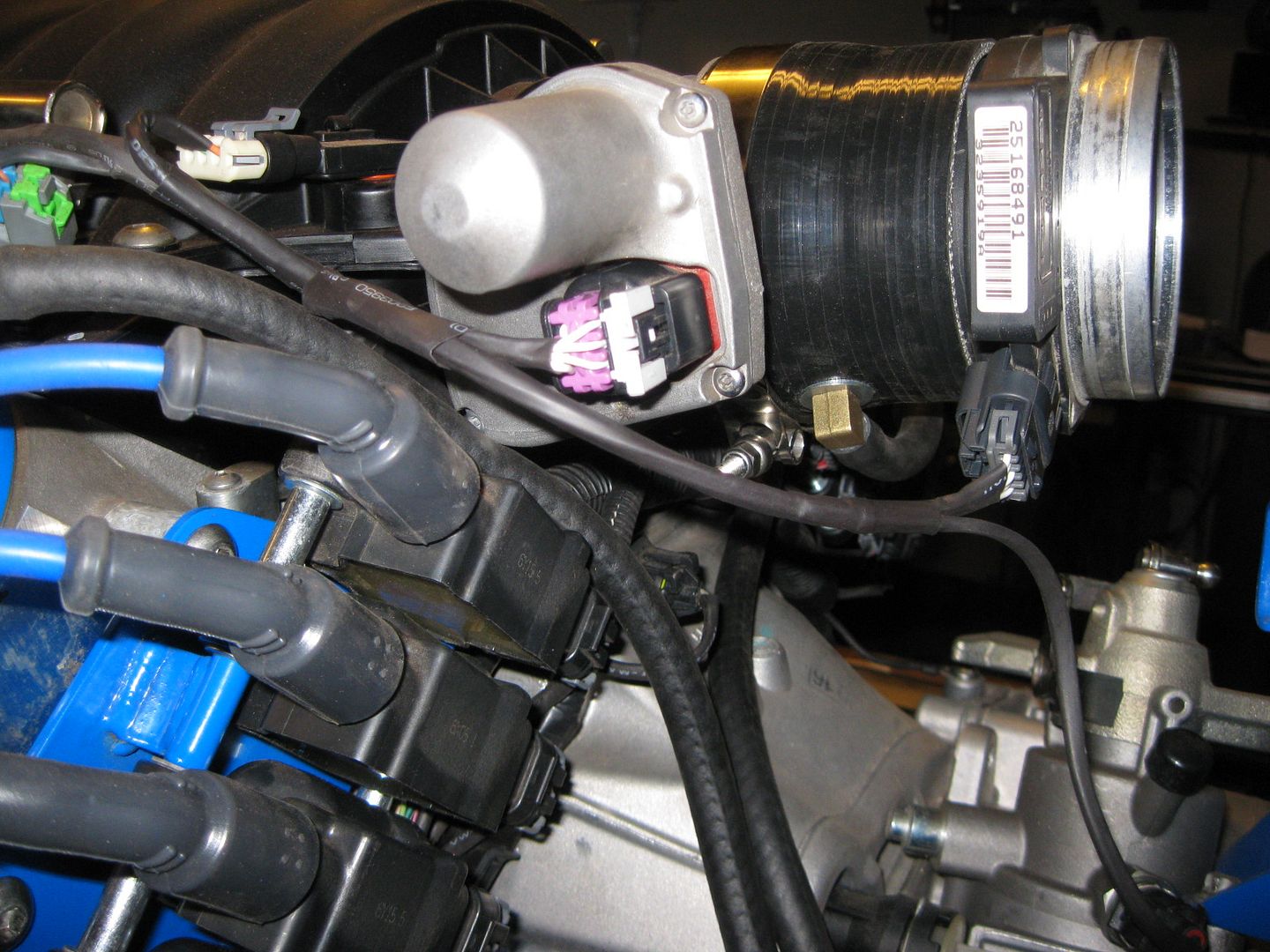
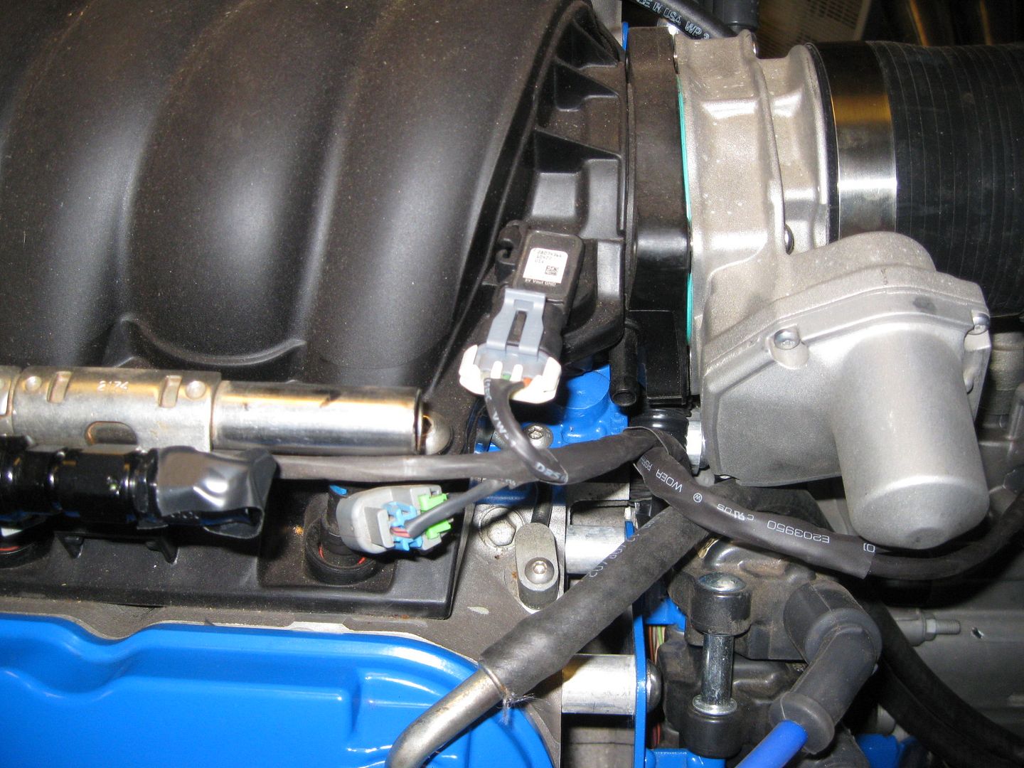
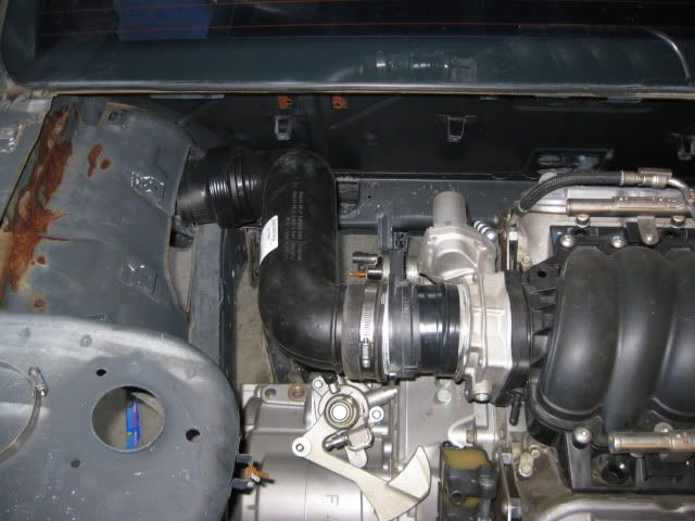
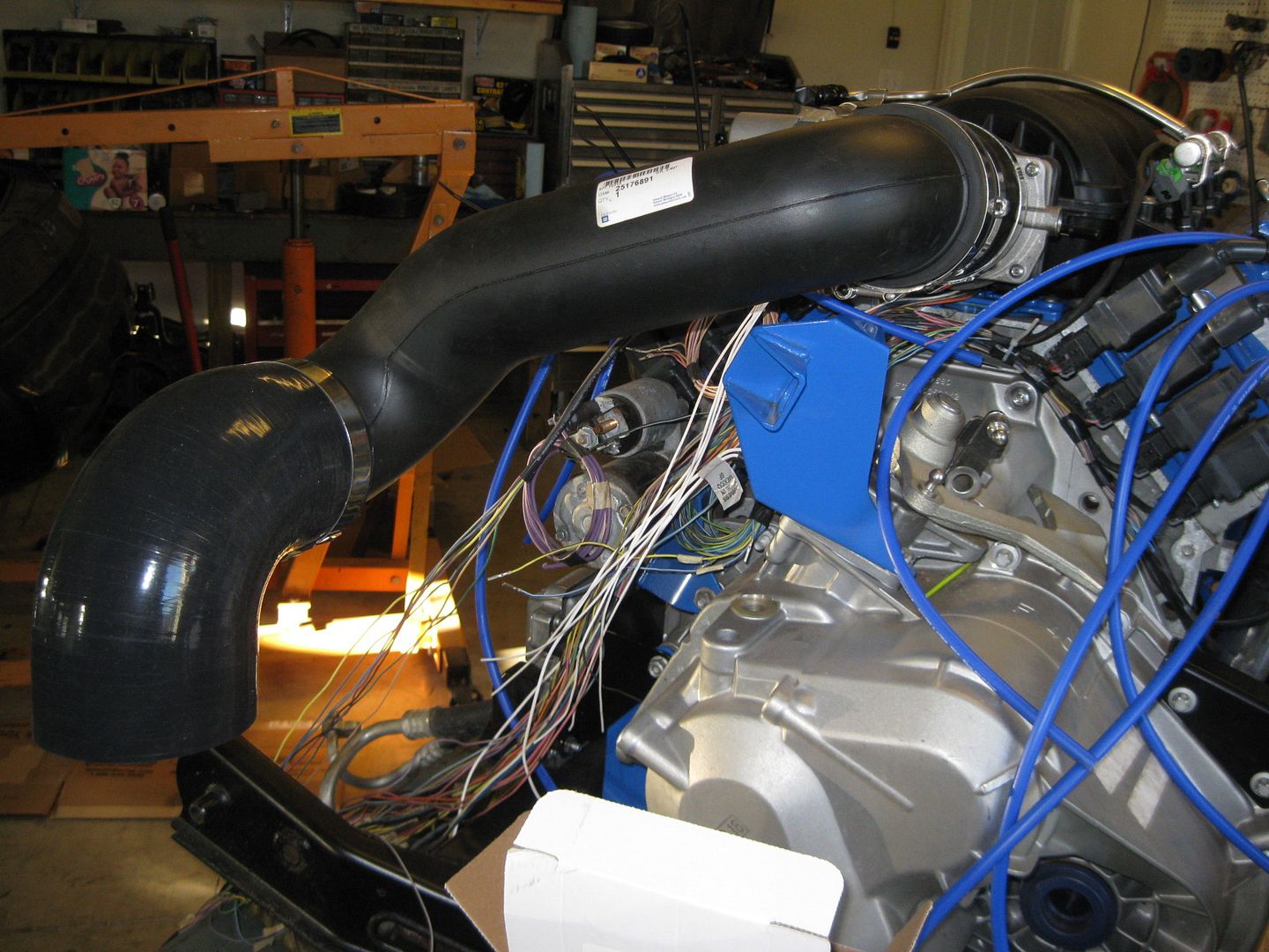
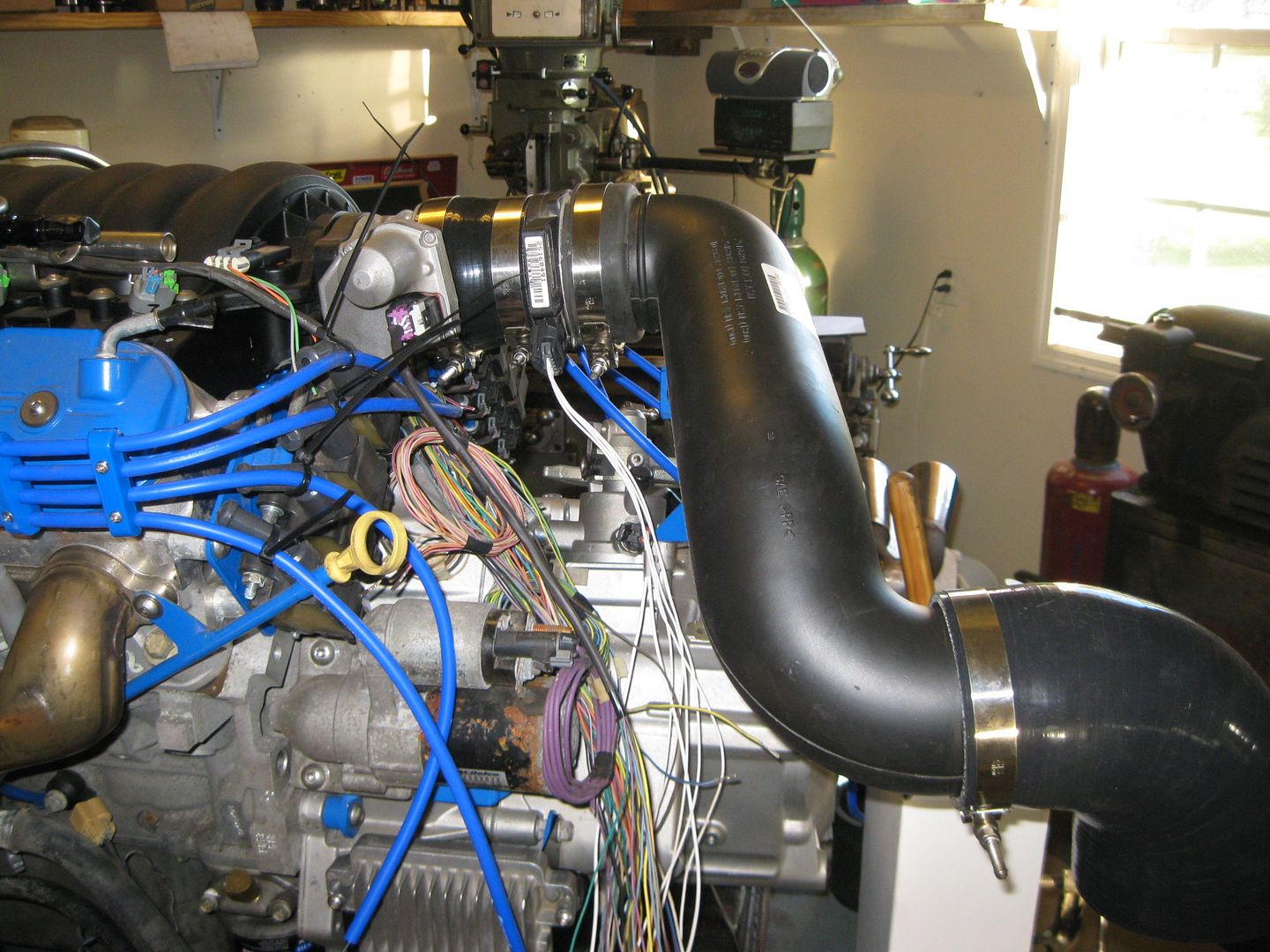
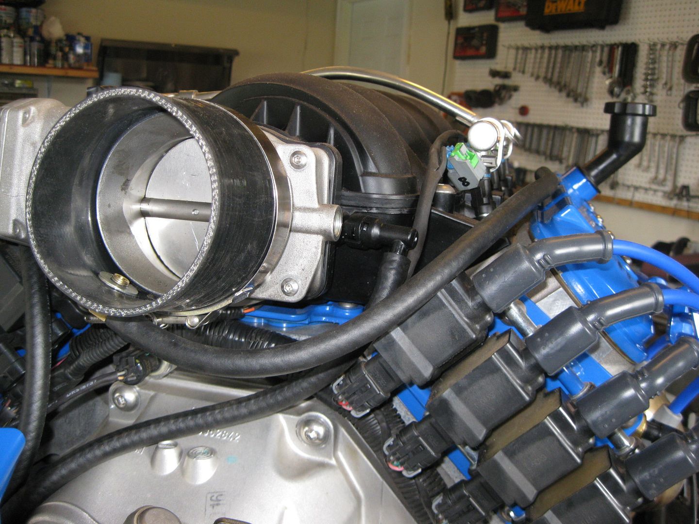
The last thing I messed with was the plastic air intake tube. I cut off the OEM expansion section and added the 90 degree elbow. Here is an old mockup pick, notice I just taped the MAF to the TB and the expansion portion was fully collapsed and wrapped with electrical tape.
Here it is again with the proper silicone reducer and the elbow:
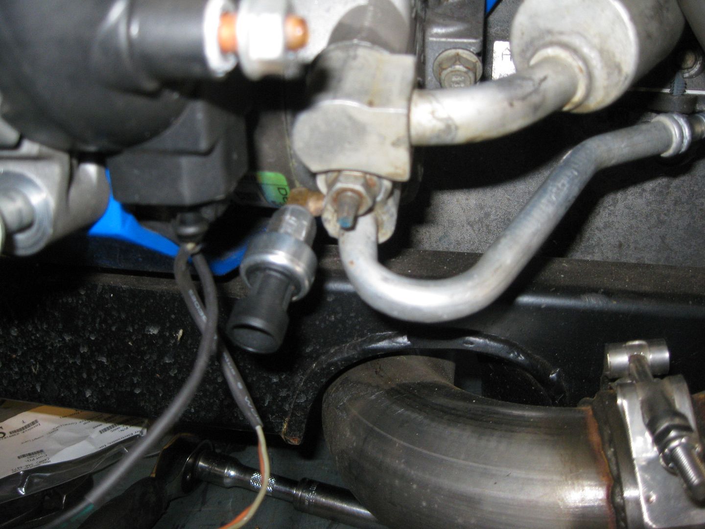
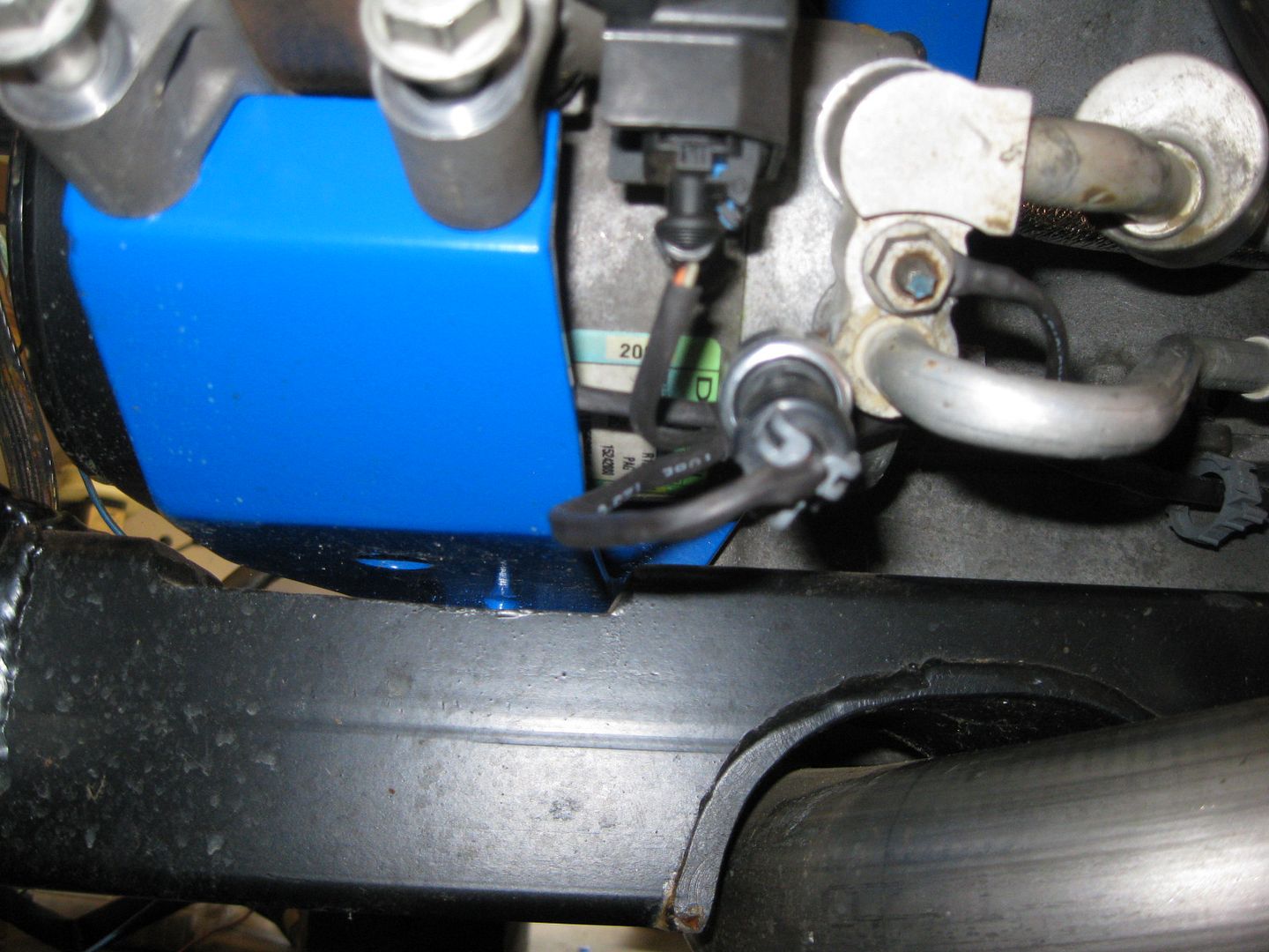
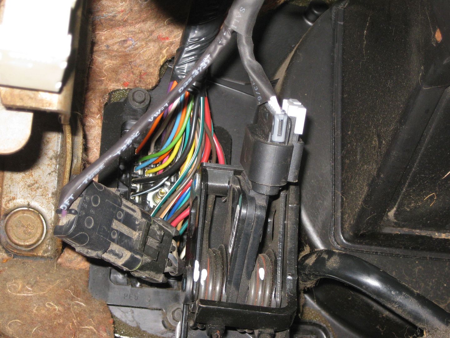
Did a little more work on the harness. The rear half of the engine harness is loomed, added the connector for the DOD circuit, installed the shrink tube on the oil pressure switch, and started to connect the MAP sensor with the front Injector harness. I seem to have lost the original 5 wire maf harness, but it might have ended up in the large box of connectors...
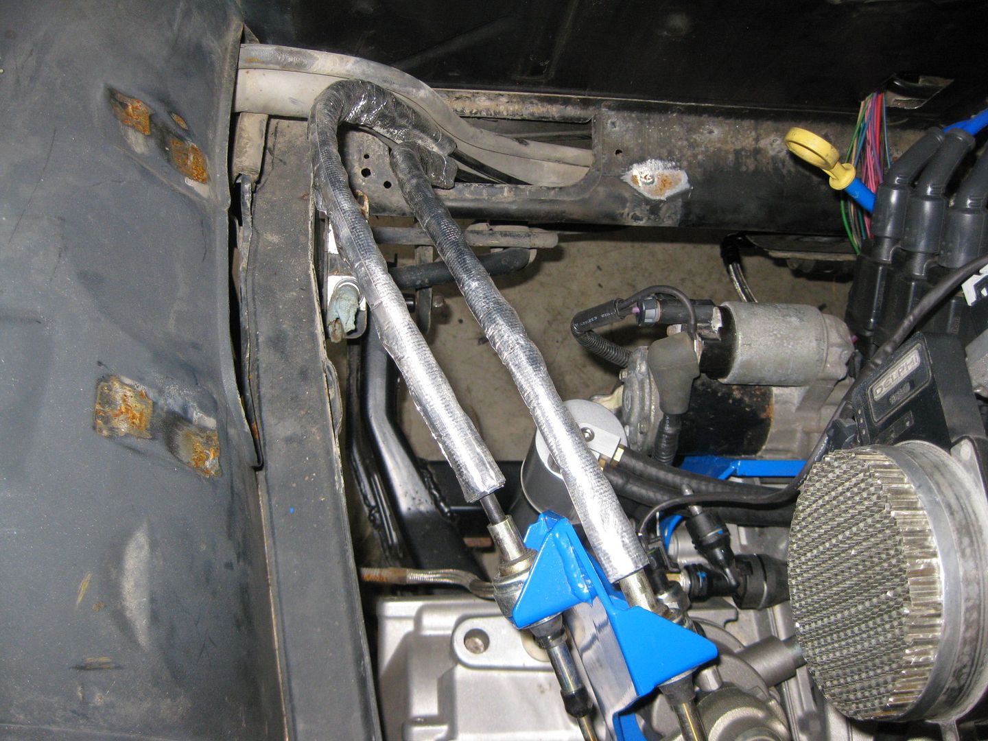
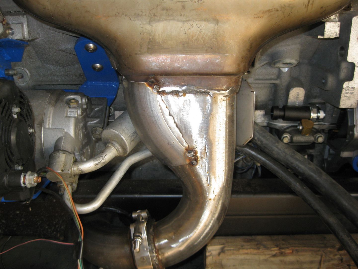
The stainless bend came in yesterday, so today I knocked out the heat shield for the front manifold to help keep the heat off the AC lines and off the harness that will run along the block.
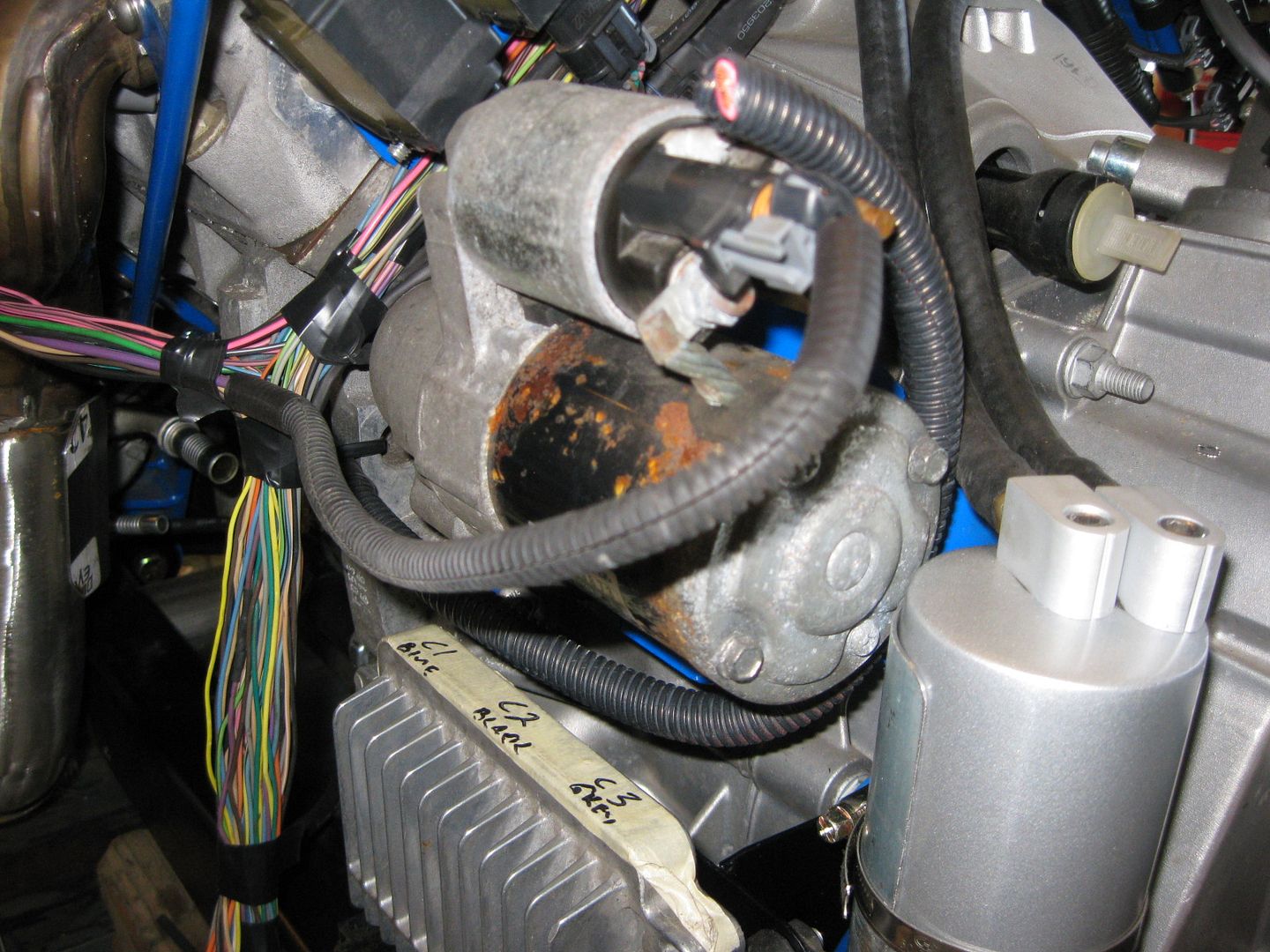
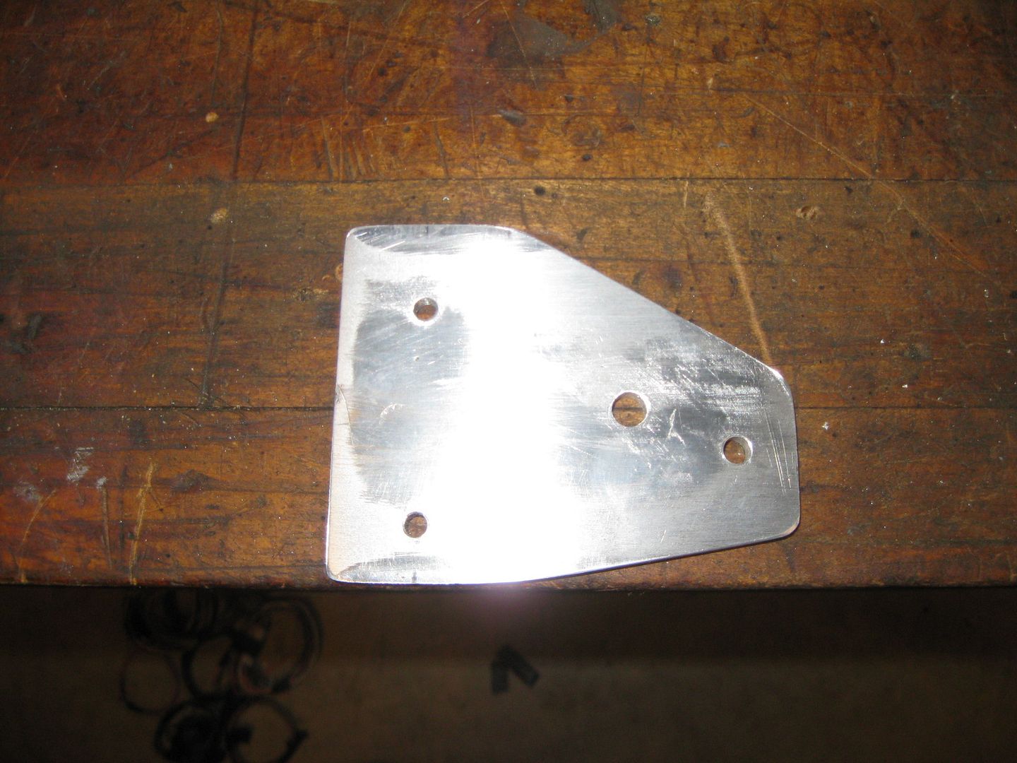
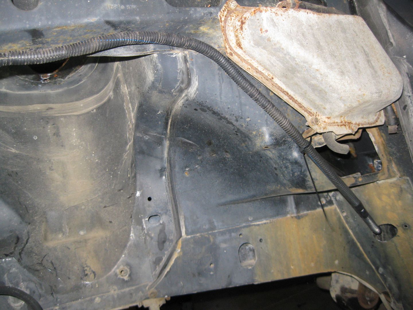
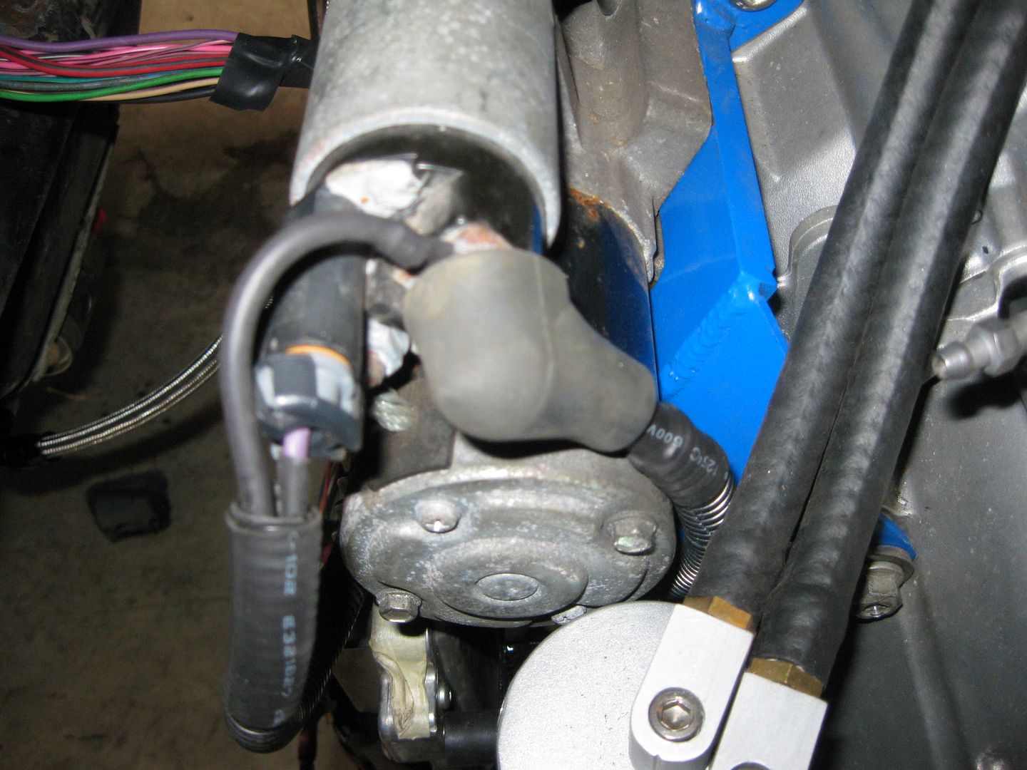
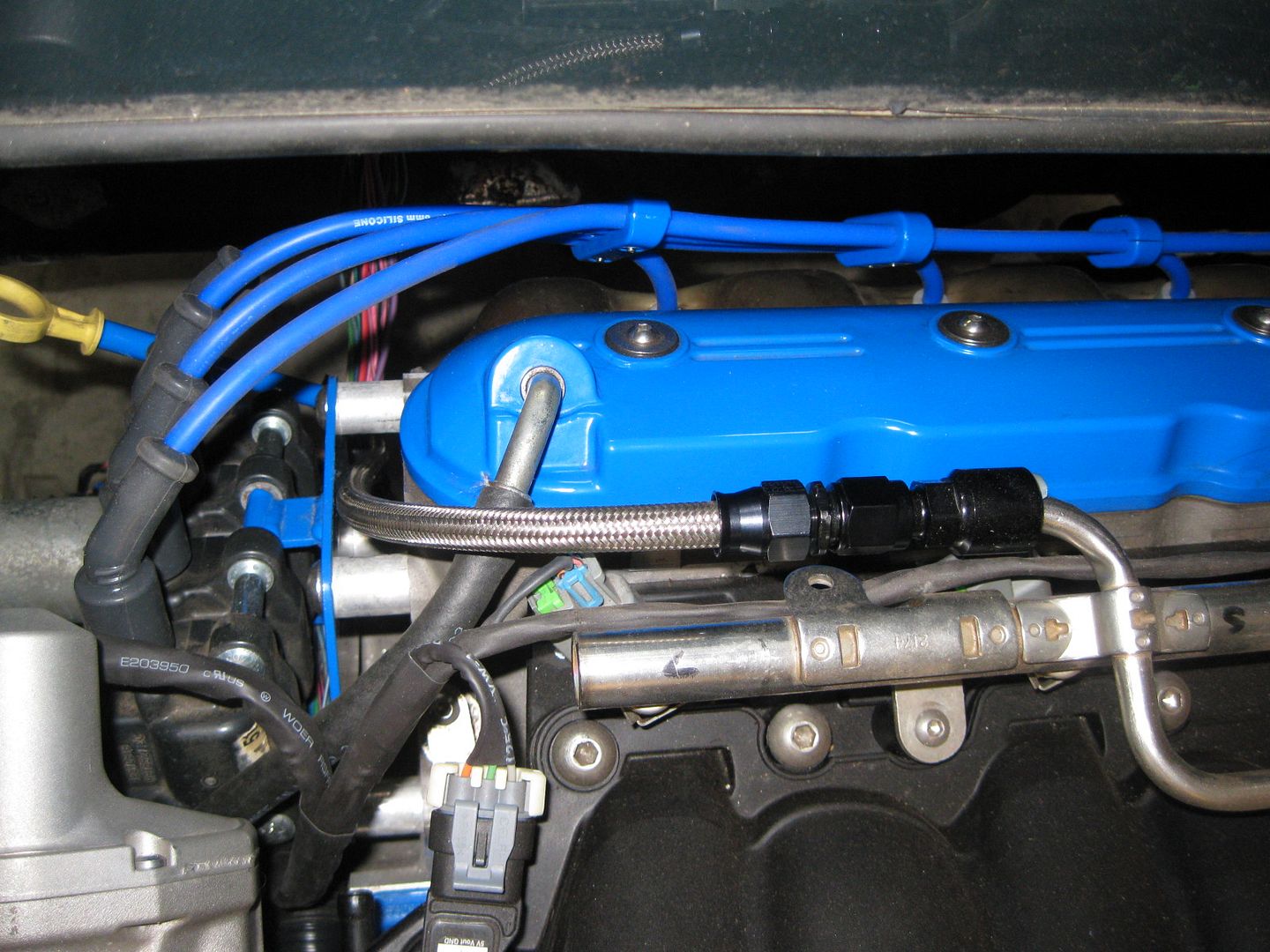
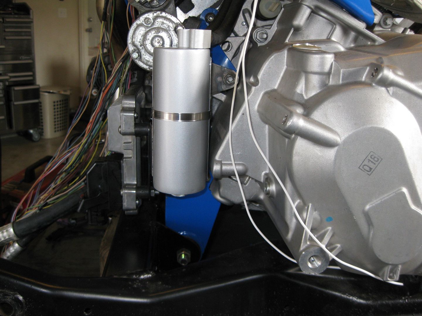
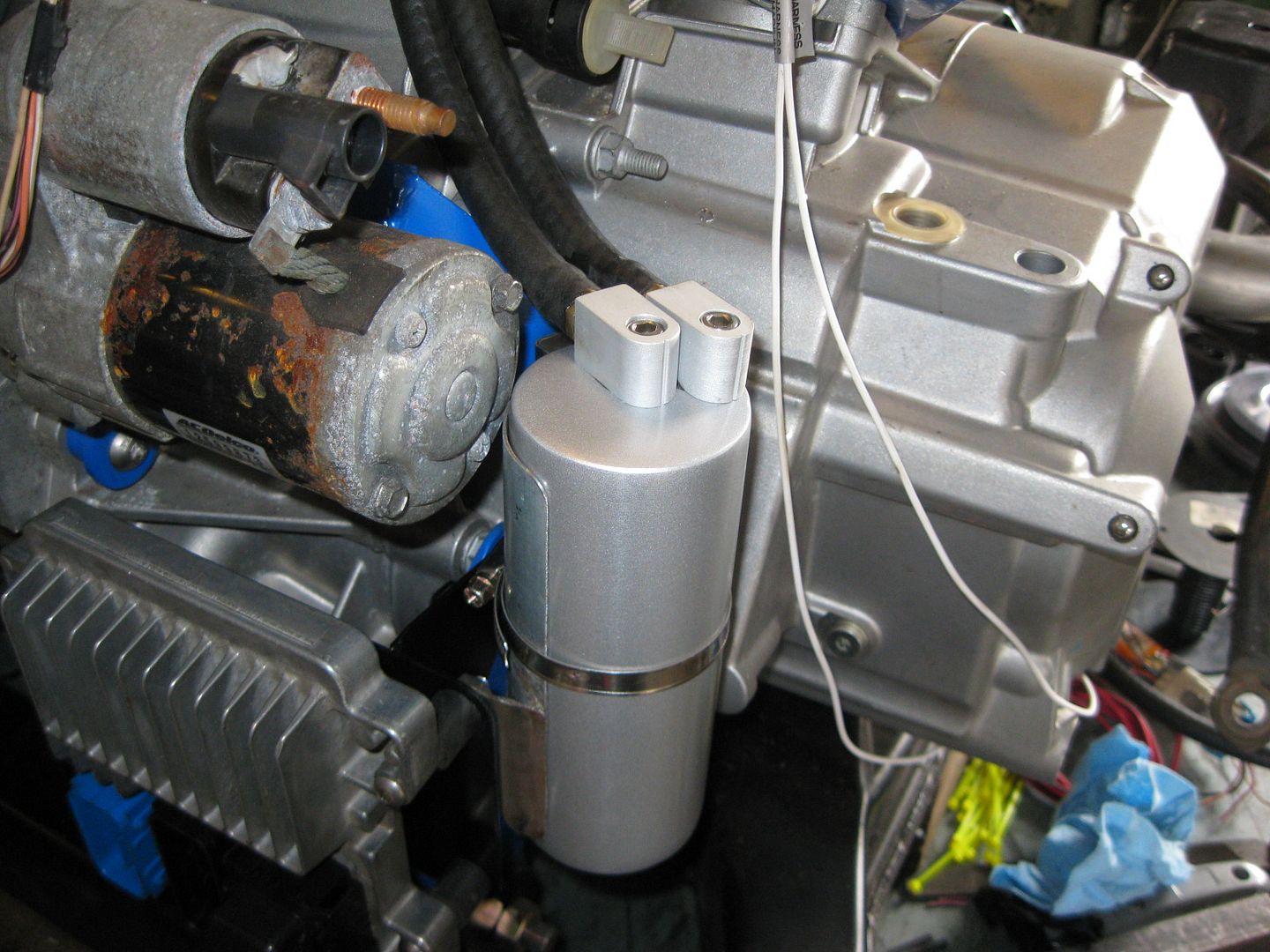
The PVC/Catch Can install is now done as well (might do something different with the rear hose running along the valve cover). Once I found the right place to mount the catch can, I fabbed up a bracket to hold it solid to the transmission:
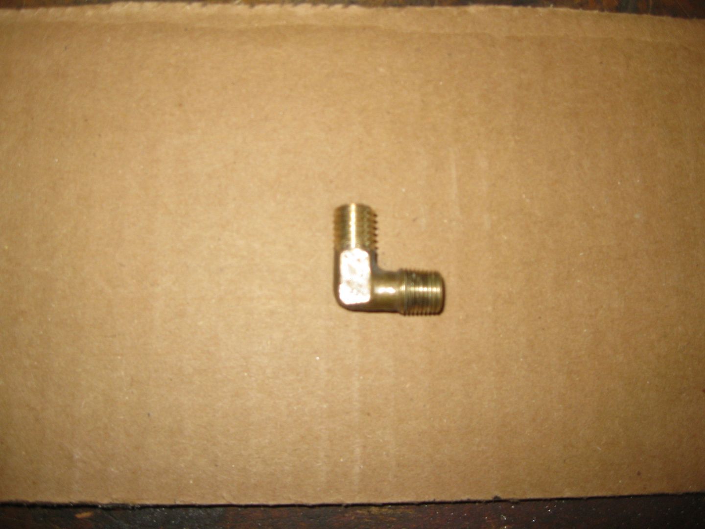
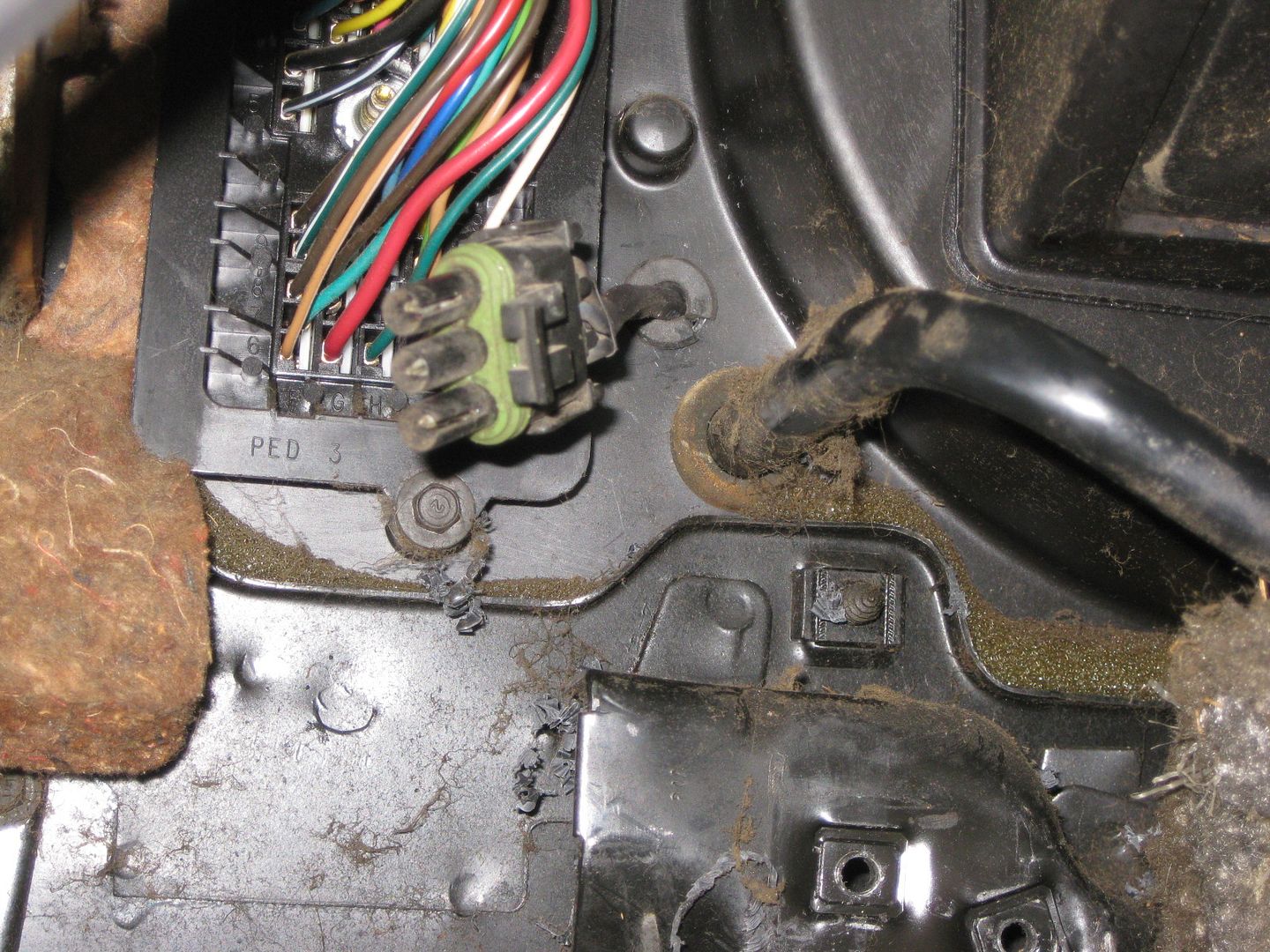
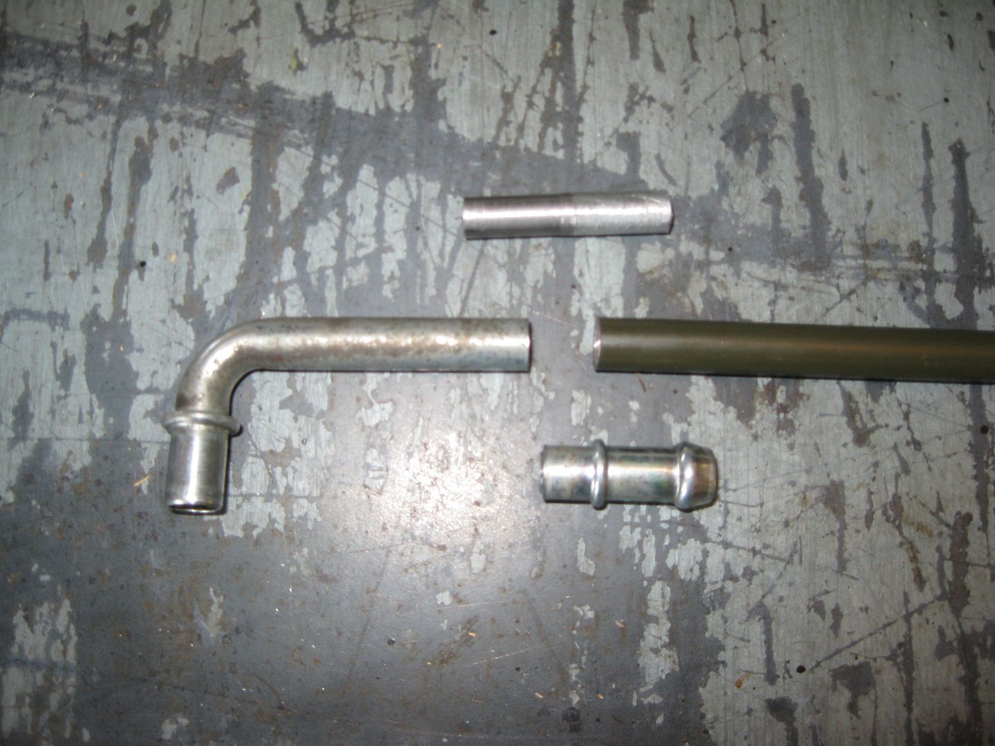
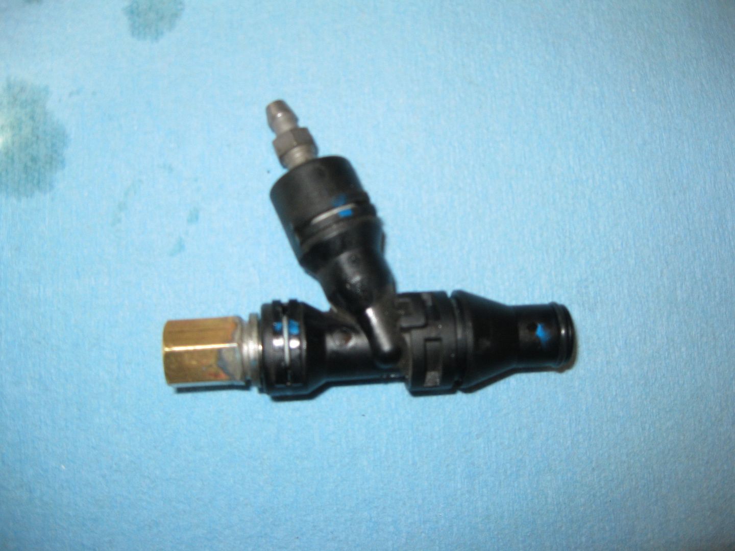
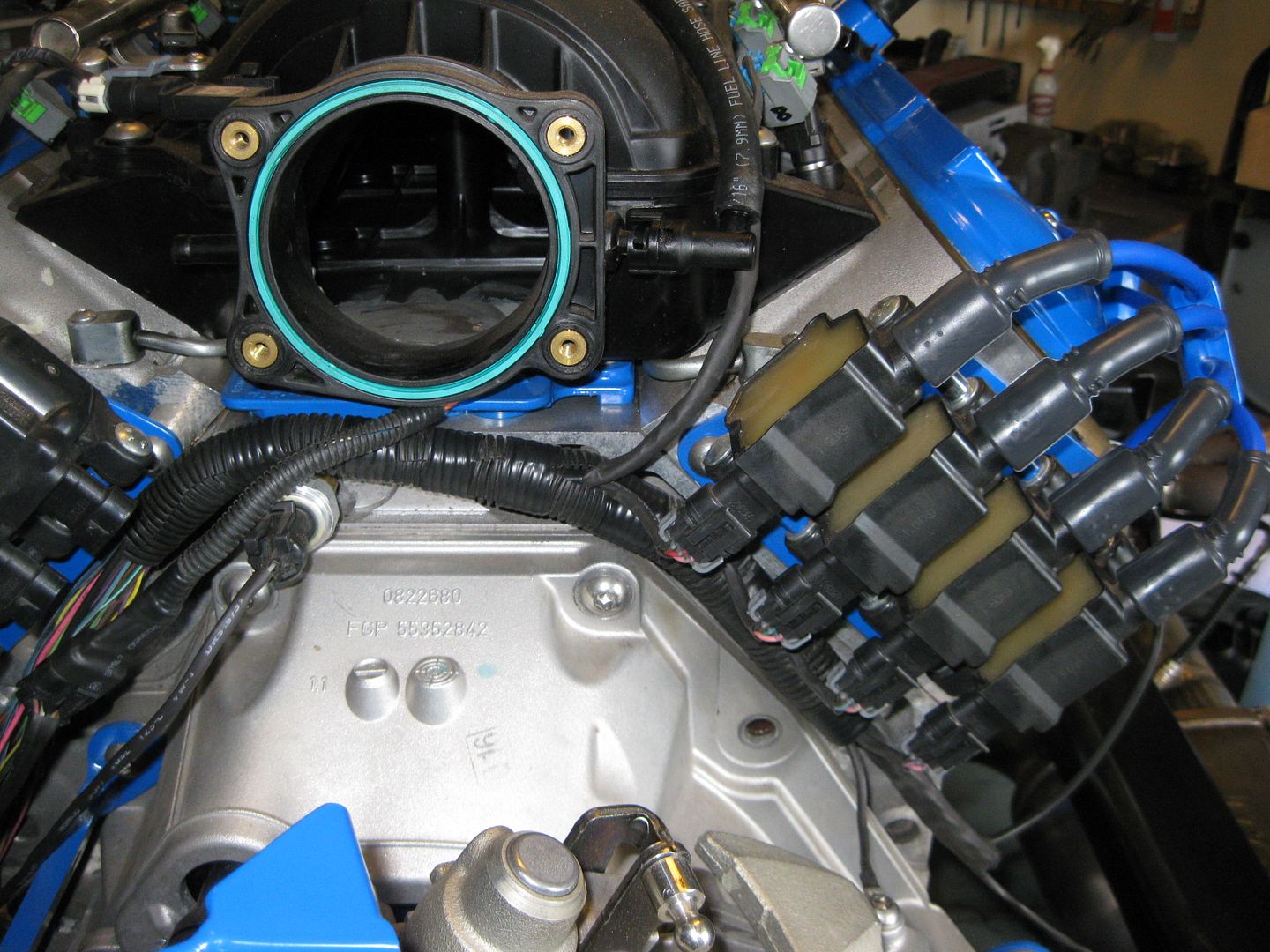
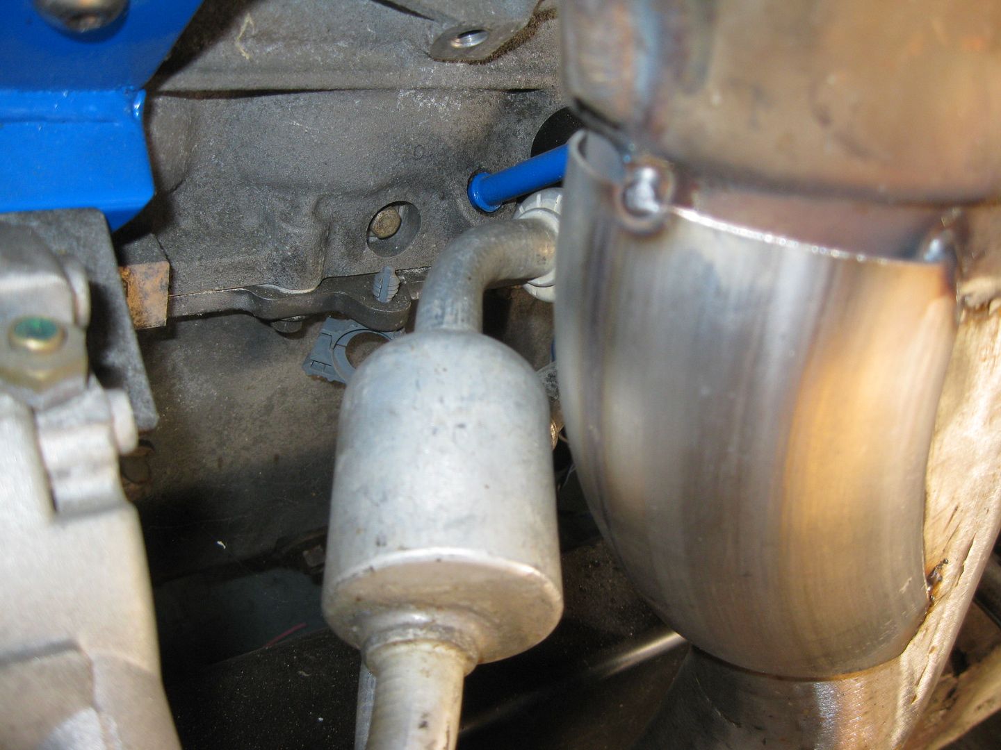
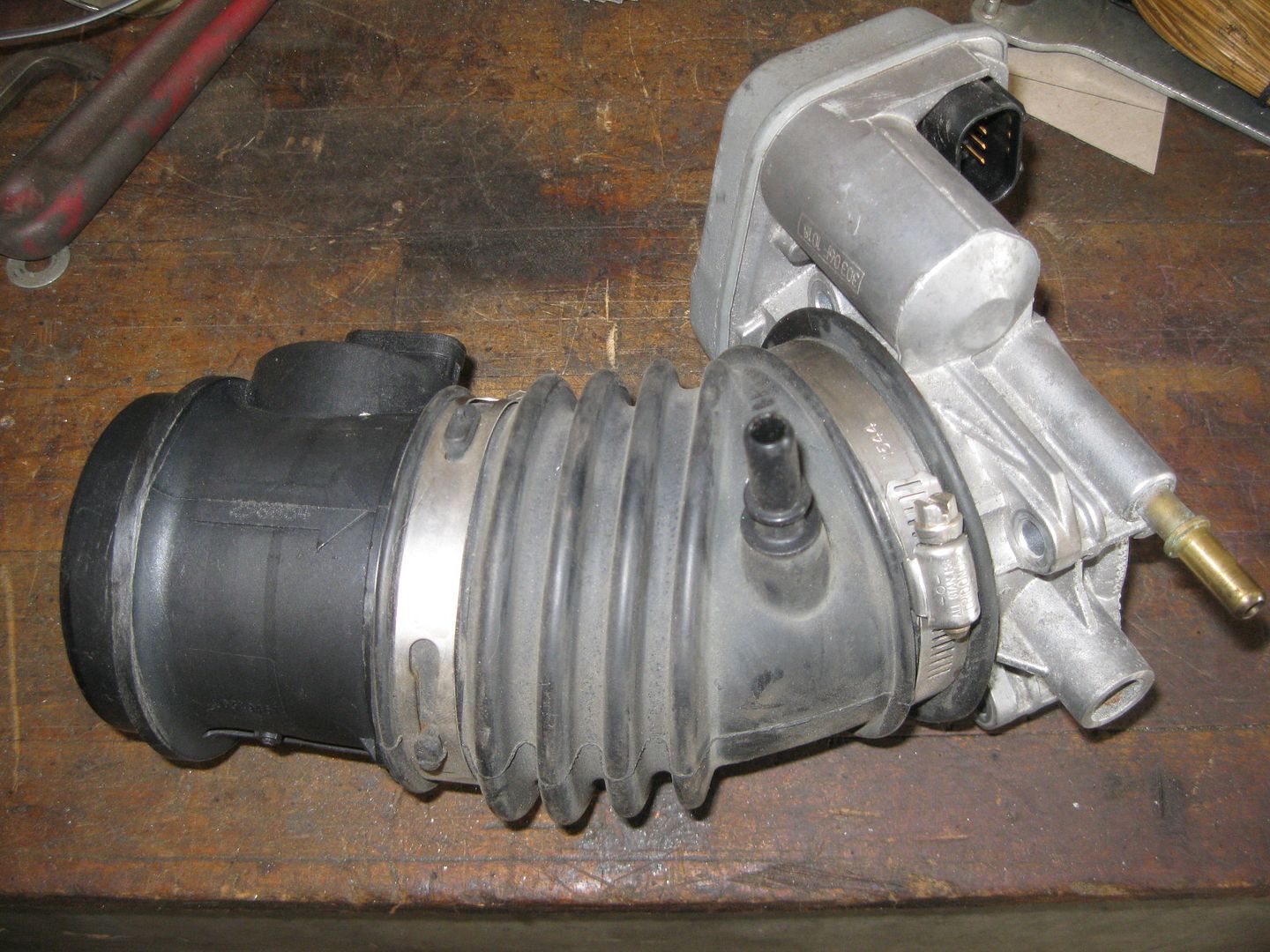
The fresh air source was a little bit of a challenge. The stock LS4 has the clean air source for the PCV system pulled from the inlet tract between the MAF and the TB, but this OEM piece will not work with the larger MAF and LS2 TB:
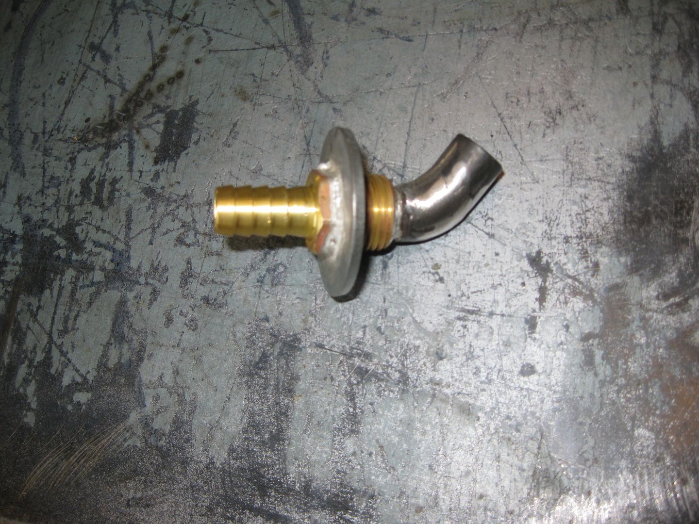
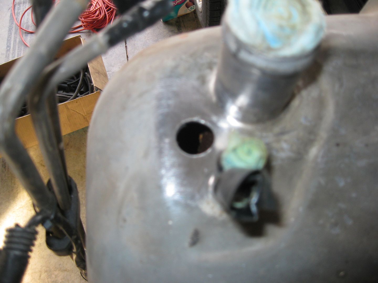
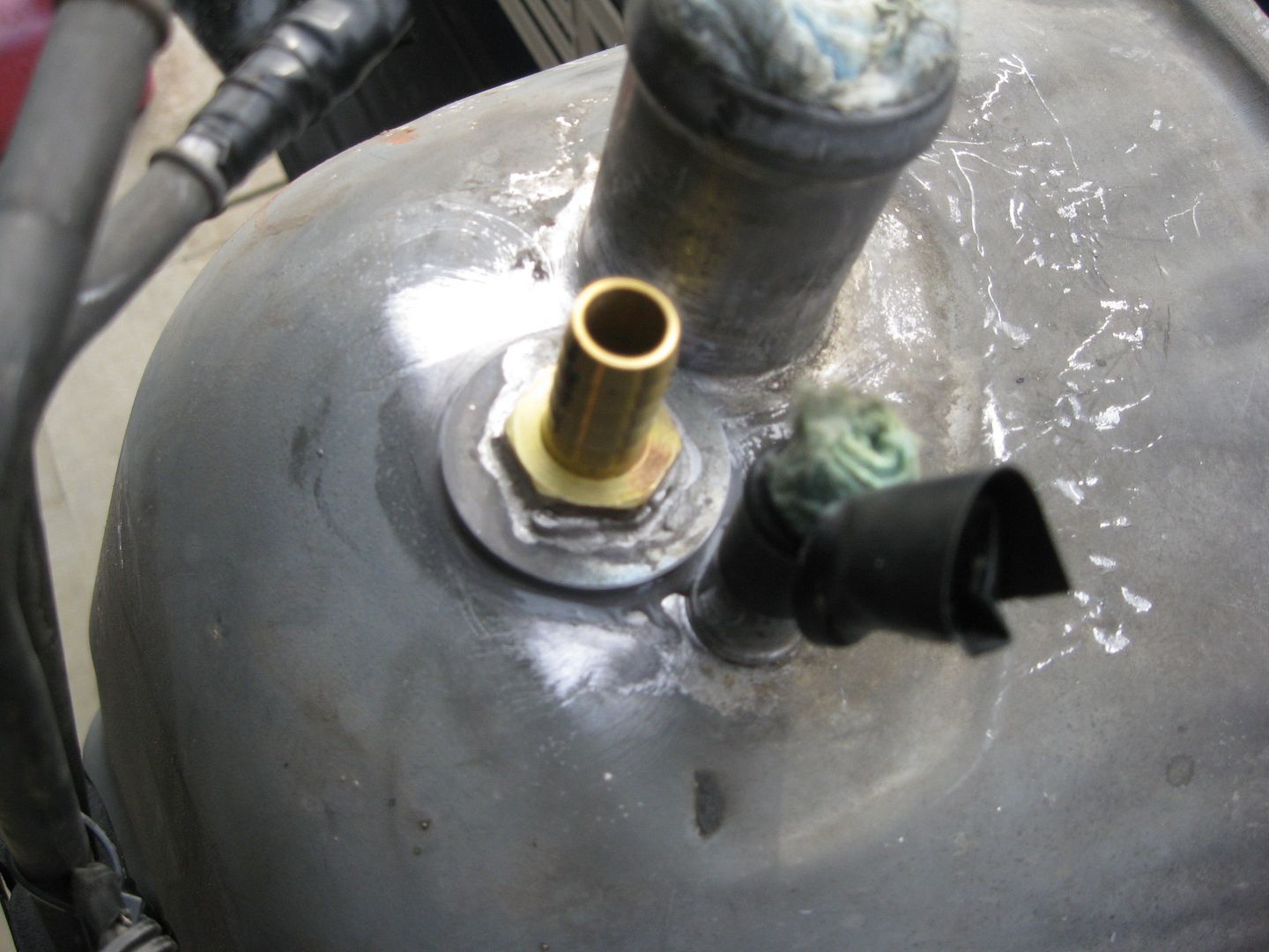
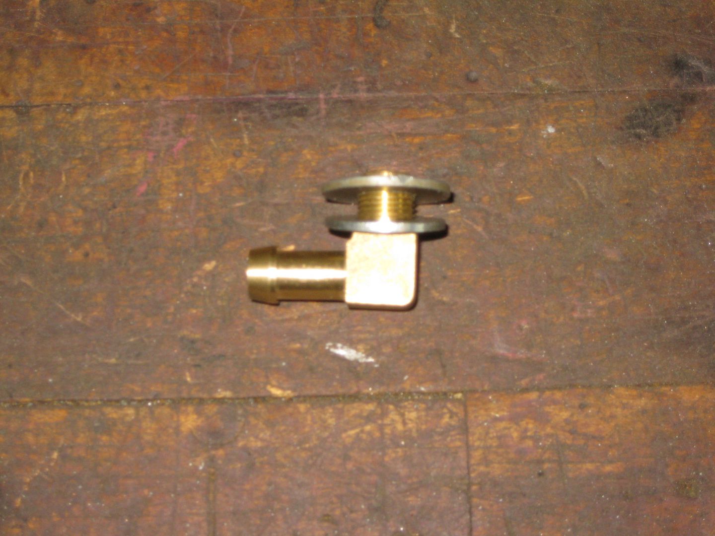
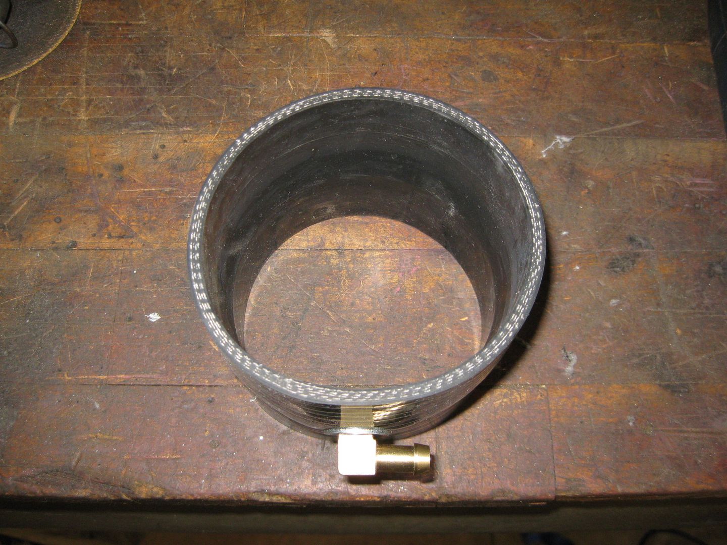
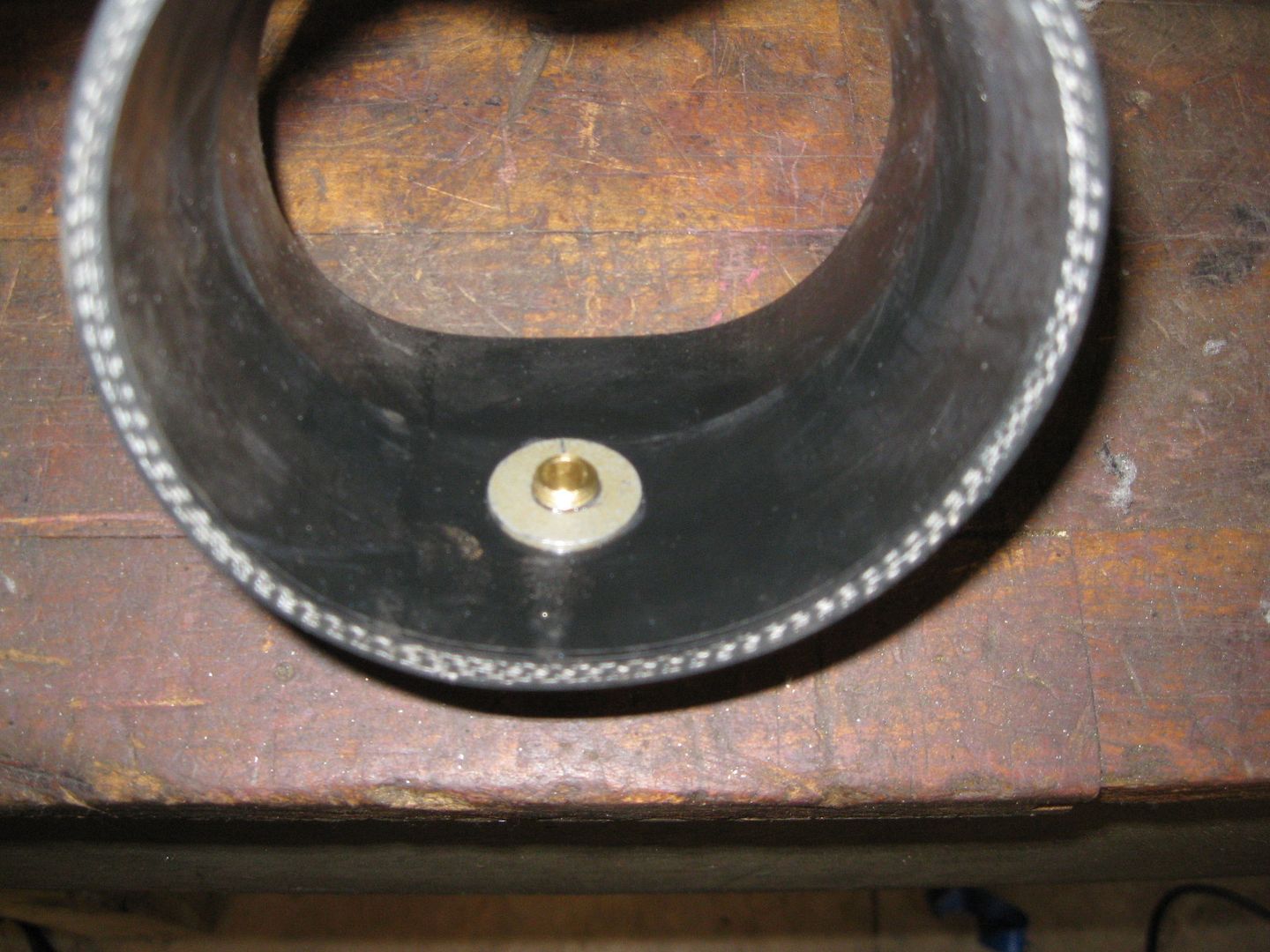
Since I am using a silicone sleeve between the MAF and Throttlebody, I needed to drill a hole and put in a hose barb fitting. I ended up taking a brass 90 fitting, found a washer that would slide past the threads and another one that didn't. Then I tapped the ID of the washer so it would become the nut for the back side. I used some RTV (between the washer and silicone sleeve) and loctite (on the threads) to ensure the washer won't come free and be ingested by the engine.
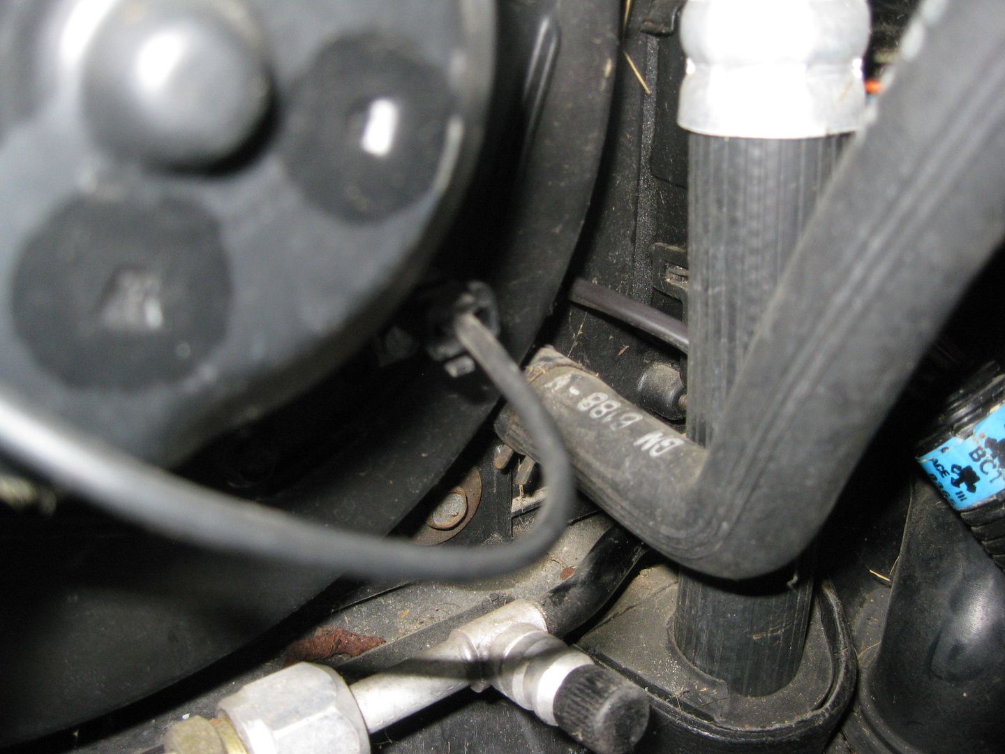
I am thinking about either making an aluminum hard line for the hose between the rear valve cover and the hose barb on the silicone sleeve or running some brake line inside the hose so I can form it to the precise shape I want (needs to run parallel with the valve cover).
I like the catch can. I must've missed where you got it from. Is there some kind of sight gauge on it to let you know it's full?
It came from eBay for under $50. It does have some fittings for the side and a section of poly tube so you can see how full it is, but it would be on the backside and not visible where the can is mounted and the direction the lines coming out the top. I need to plug the original holes and drill/tap 2 new ones on the outer edge so I can see the level through the wheel well.
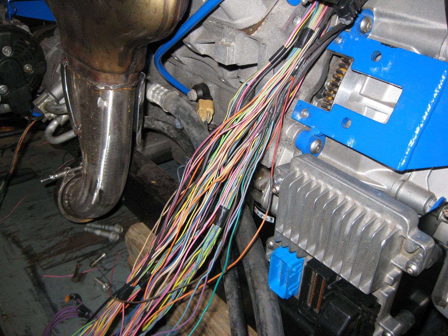
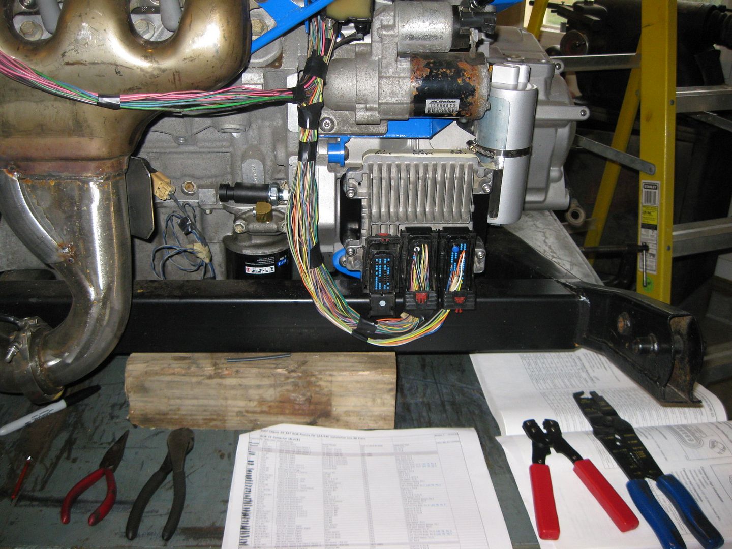
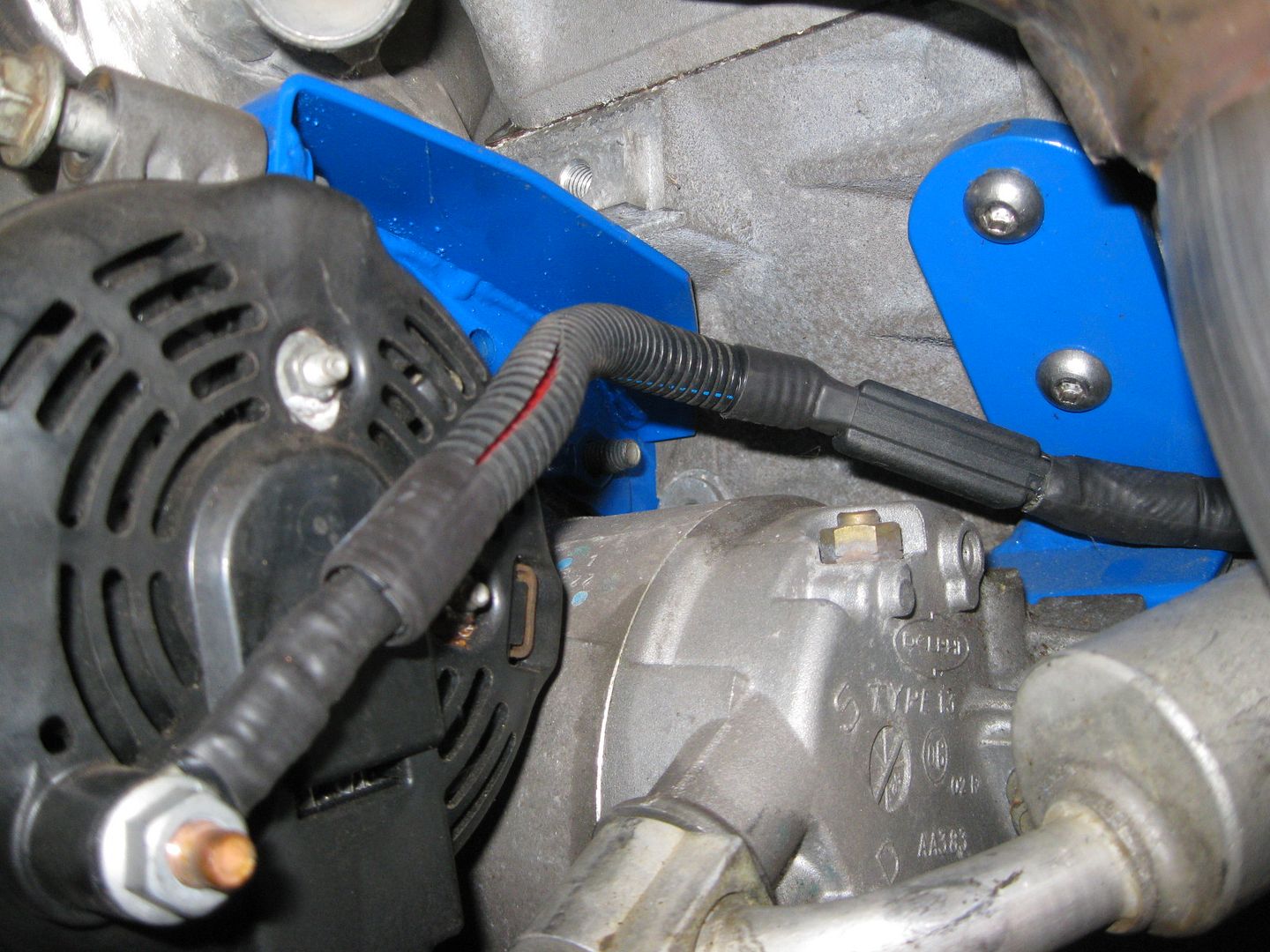
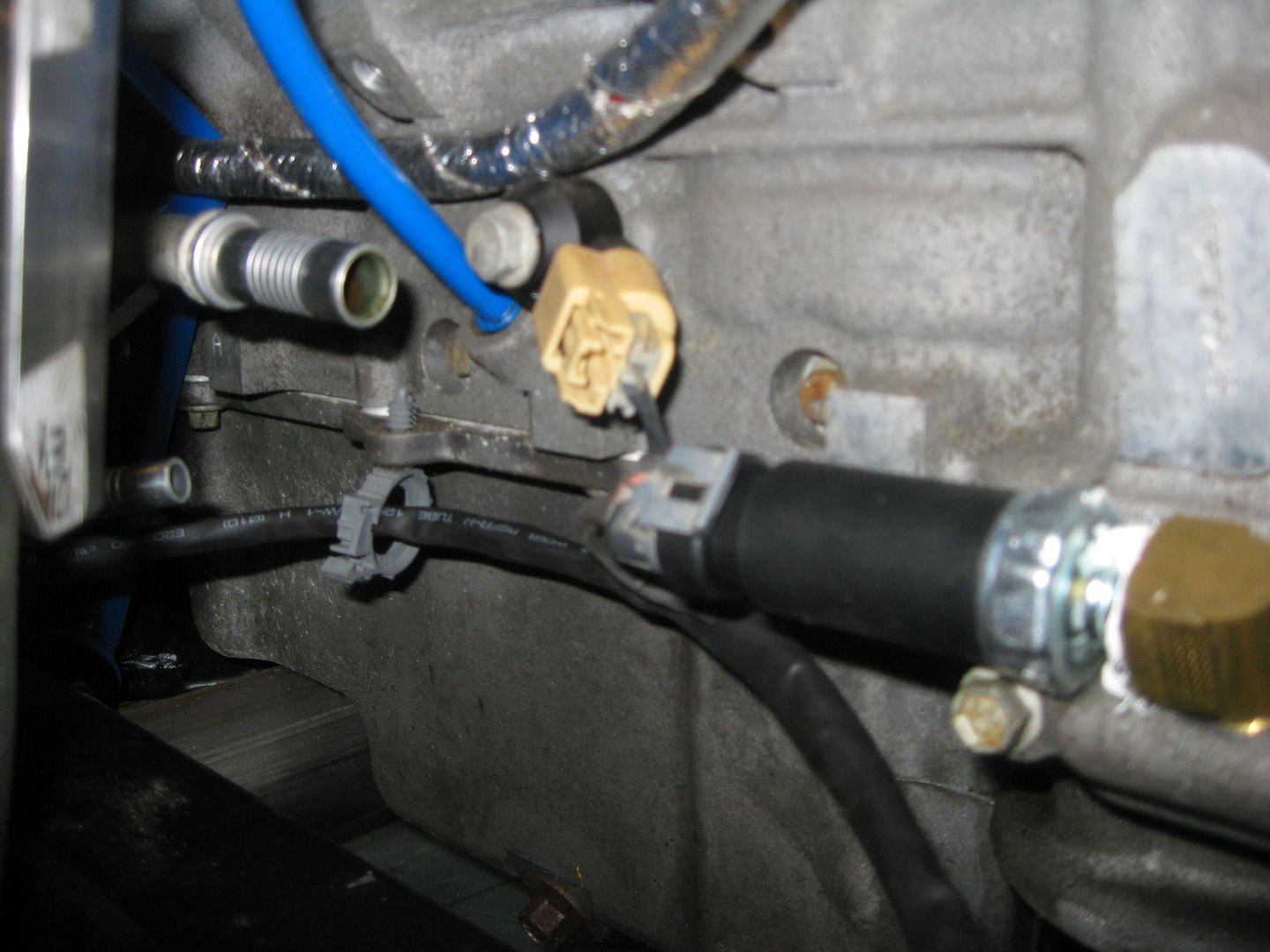
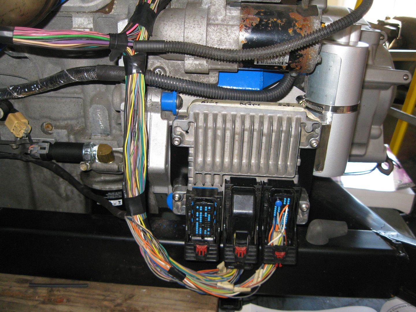
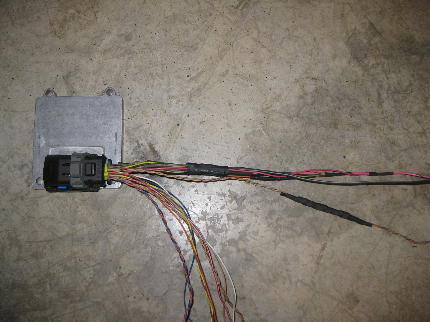
Did a little more on the harness. Everything on the rear and top side is loomed down to the starter. Still need to loom up the front side (alternator, AC, Knock, Oil Pressure), then I can start the termination process at the ECM, then install the engine for all the terminations inside the car (500, 203, Fuel and AC relays, DBW pedal, etc).
Spent most of the day documenting the wire/circuit/sensor terminations for all the ECM connectors and the Fiero 203/500 specific to this swap. As I decide what to keep/omit, I wanted to know what all te inhibitors were for DoD activation. Here is a list:
1. Engine manifold vacuum low 2. Brake booster vacuum pressure low 3. Accelerator pedal position rate of increase too high, electronic throttle control 4. Accelerator pedal position too high, electronic throttle control 5. Ignition voltage out of range 6. Engine oil pressure out of range 7. Engine oil temperature out of range 8. Engine RPM out of range 9. Transmission gear incorrect 10. Transmission range incorrect 11. Transmission gear shift in progress 12. All cylinders activated via scan tool output control 13. Minimum time in V8 mode not met 14. Maximum V4 mode time exceeded 15. Engine oil aeration present 16. Decel fuel cutoff active 17. Fuel shut-off timer active 18. Minimum heater temp low, HVAC system 19. Reduced engine power active, electronic throttle control 20. Brake torque management active 21. Axle torque limiting active 22. Engine metal over temperature protection active 23. Catalytic converter over temperature protection active 24. Piston protection active, knock detected 25. Hot coolant mode 26. Engine over speed protection active 27. Fault active or Fault Pending - cylinder deactivation is disabled for the following faults: *** Brake Booster Vacuum Sensor *** Manifold Absolute Pressure Sensor *** Engine Oil Pressure Sensor *** Engine Coolant Temperature Sensor *** Vehicle Speed Sensor *** Crankshaft Position Sensor *** Engine Misfire Detected *** Cylinder Deactivation Solenoid Driver Circuit
As you can see the DoD setup is quite finicky and everything has to be in the programed ranges for it to work. Now as I try to get the system to work with a manual transmission, these are my 4 biggest concerns.
9. Transmission gear incorrect 10. Transmission range incorrect 11. Transmission gear shift in progress *** Vehicle Speed Sensor
All communication about the transmission (Gear, Range or mid-shift) only happens through the High Speed GMLAN Serial Data Bus and there are no traditional inputs to the ECM for these. So if I need to fake the ECM into thinking it is in Drive, and 4th gear is engaged, then all that trickery has to happen on the TCM.
My concern about the VSS is that the two VSS wires go to the VSS and only a single VSS wire goes from the TCM to ECM (stock E67 LS4 calibration). Many other swaps using the E67 in a manual configuration were able to run both VSS wires directly to the ECM and get the Speedo to work, but the vehicle speed within the ECM (from a scanner) wouldn't show vehicle speed. The concern is if the ECM doesn't show the vehicle speed, will it enable DoD, or is it even looking for the VSS approval from the ECM, or does it come from the TCM through the High Speed GMLAN Serial Data Bus...
Probably the safest bet it to plan on installing the TCM in the center console area...
Originally posted by fieroguru: My concern about the VSS is that the two VSS wires go to the VSS and only a single VSS wire goes from the TCM to ECM (stock E67 LS4 calibration). Many other swaps using the E67 in a manual configuration were able to run both VSS wires directly to the ECM and get the Speedo to work, but the vehicle speed within the ECM (from a scanner) wouldn't show vehicle speed. The concern is if the ECM doesn't show the vehicle speed, will it enable DoD, or is it even looking for the VSS approval from the ECM, or does it come from the TCM through the High Speed GMLAN Serial Data Bus...
Probably the safest bet it to plan on installing the TCM in the center console area...
The E67 manual swaps you refer to are DoD/AFM-free swaps I presume, and don't have TCMs? Or have other people swapped in DoD engines with manual transmissions somewhere that I haven't seen yet? Would like to see more information on them if so.
Are you planning to use the 4t65e TCM from an LS4 car, or some other solution that could actually determine gear from speed/load/etc… inputs based on programming of gear ratios from the trans, and tire size?
Originally posted by dobey: The E67 manual swaps you refer to are DoD/AFM-free swaps I presume, and don't have TCMs? Or have other people swapped in DoD engines with manual transmissions somewhere that I haven't seen yet? Would like to see more information on them if so.
Are you planning to use the 4t65e TCM from an LS4 car, or some other solution that could actually determine gear from speed/load/etc… inputs based on programming of gear ratios from the trans, and tire size?
Correct. There are no E67 applications with DoD/AFM and a manual transmission, and no known completed manual swaps that kept DoD... I am a glutton for punishment.
I am planning to keep the stock 4T65e-hd TCM to start with. The crazy idea I have is to hardwire the TCM inputs so the TCM thinks its in Drive (at shifter) and in 4th (actual drive gear) and then let the VSS speed change. Might play with some bulbs and resistors to get everything to be correct for these parameters as that is what DoD is looking for. So my trigger for DoD will largely be RPM and VSS driven (given MAP and all the other factors are in range). If I restrict the RPM to be between 1600 and 2300 and the vehicle speed to be above 55 mph, then from 55 to 65 DoD would work in 5th or 6th gears and from 65 to 79 it would only work in 6th. My goal with the manual setup is to only have DoD function at highway/interstate speeds... mainly because it will sound like crap in 4 cyl mode with my loud exhaust, and I want it to sound good while tooling through town...
I still need to document all the TCM pin locations and resistance values for all the solenoids and pressure/temp sensors to see what my options are.
[This message has been edited by fieroguru (edited 10-16-2012).]
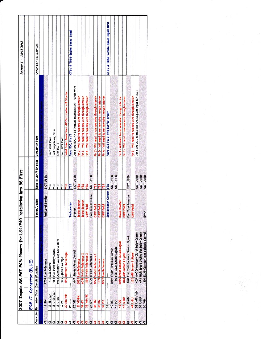
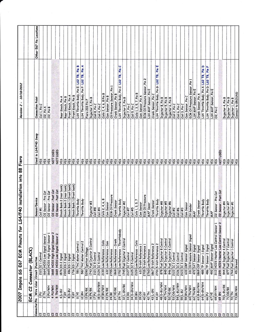
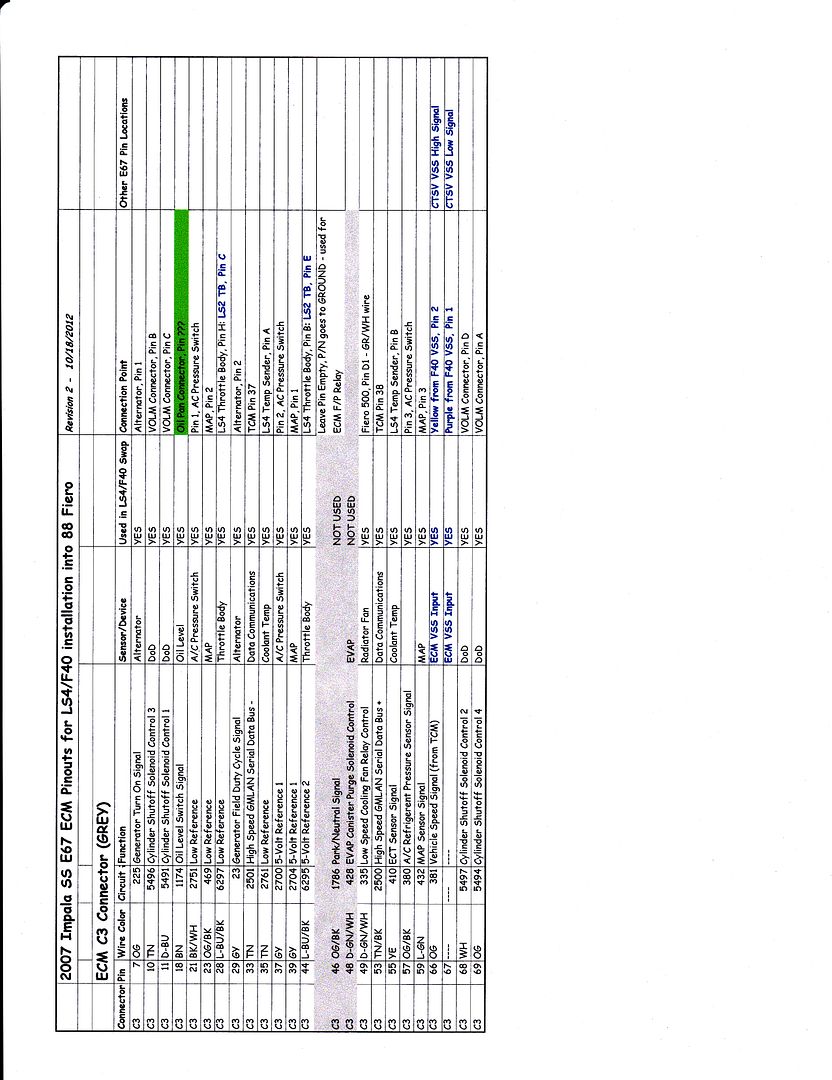
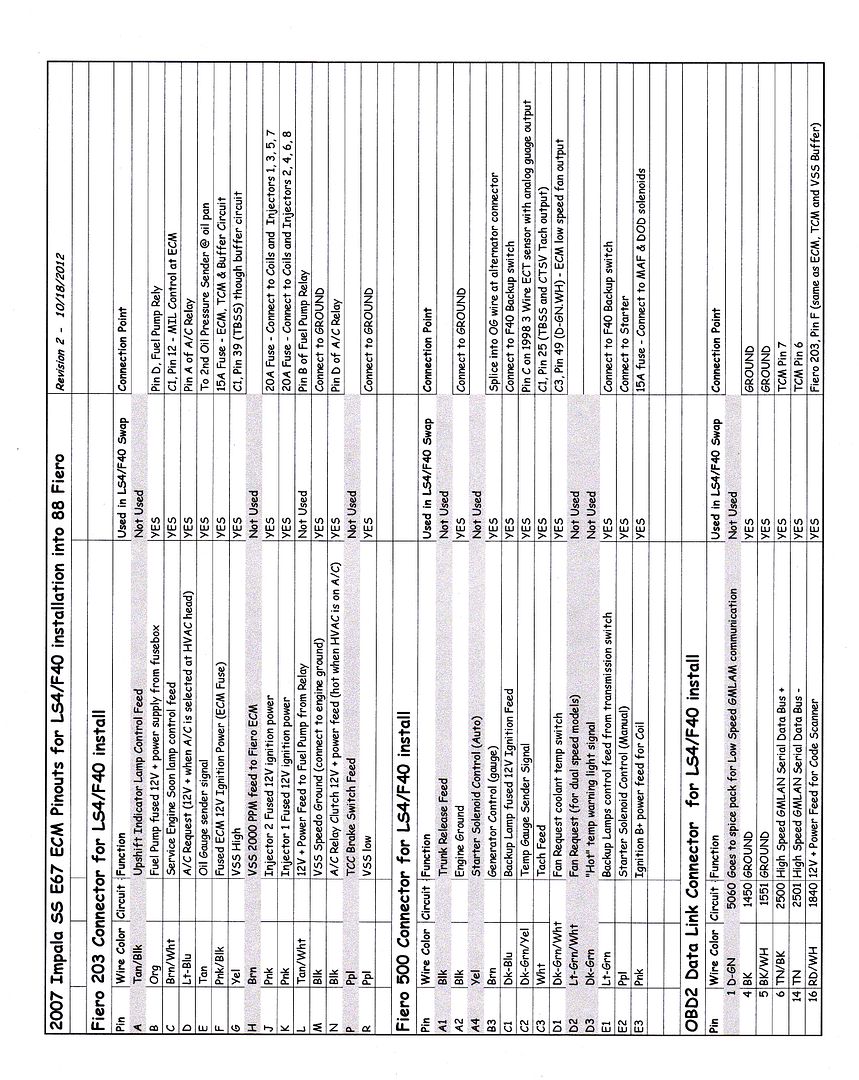
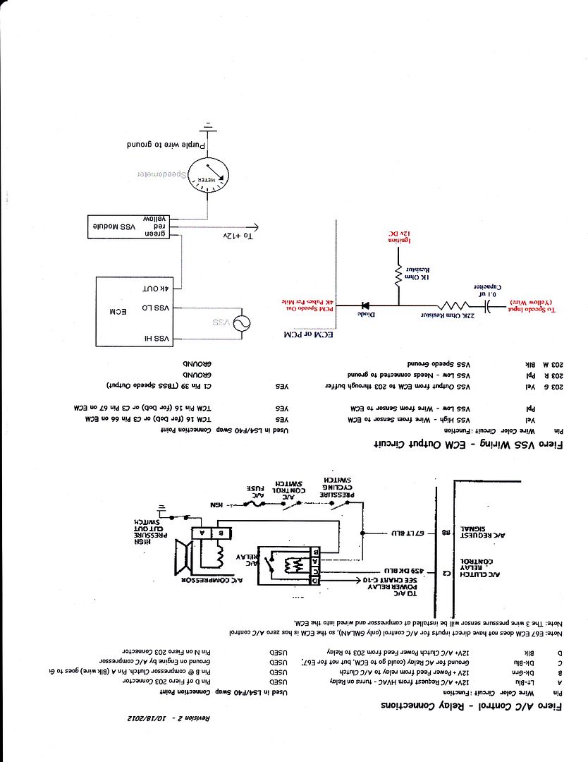
Speaking of documenting... I am nearly done with all the ECM/203/500 termination documentation (might have a few typo's still) and I hope the E67 LS4 guys will find this helpful.
EDIT: Drawings updated for some revisions on 10/18... If you saved the earlier versions, delete them and save the current ones.
[This message has been edited by fieroguru (edited 10-18-2012).]
I updated the wiring documents above, so if you save them already, you probably want the revisions (added the DCL connector and updates lots of info in the other connectors).
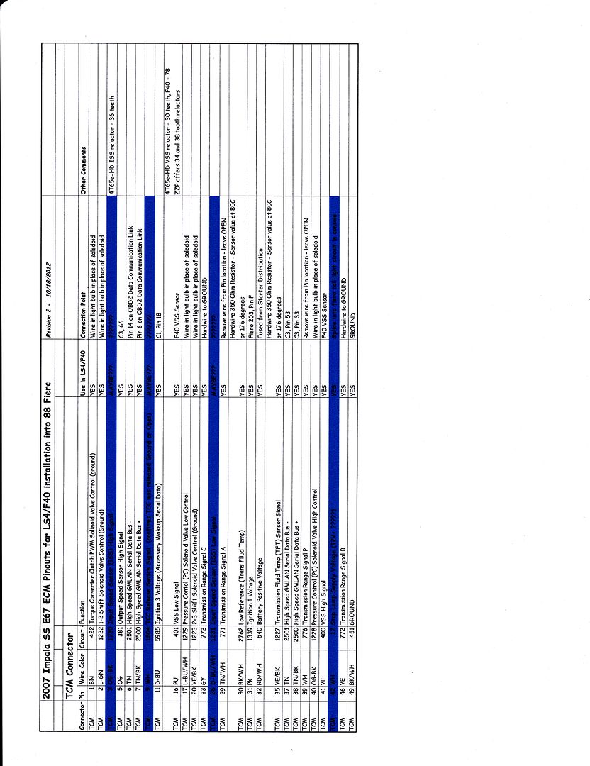
The electrical circuit side is one of my weaknesses... so as I look at what I can do to fool the TCM into thinking the 4T65e-hd is still present and working, I am taking a rather simplistic approach... and likely doing some things wrong. Any TCM circuit experts feel free to provide other suggestions.
The major unknown right now is how much of the TCM functions have to be correct in order for the TCM to give the ECM the go ahead for DoD activation. So at this point I am planning to error on the side of doing too much (I can always remove them later) vs. not doing enough and having to revisit the issue. The chart below has the majority of my thoughts/plans, but a high level plan of action:
1: Hard wire the inputs from the Range Selections so the TCM see's the transmission in DRIVE 2: All solenoid circuits wired up with fiero side marker light bulbs so they will see a load. 3: Wire up the fluid Temp with a resistor so the TCM thinks the transmission is at about 175 degrees 4: Connect all the normal wires between the TCM/ECM and external inputs as normal
Once those are done, I am down to two issues. The VSS could be connected from the F40 to the TCM.... But then the TCM will see the 60Kppm vs 24K... Might just add a 30 tooth reluctor on the tripod housing or intermediate shaft (unless I can just progam the TCM to look for the 60K ppm input). The ISS... only way to mimic this signal is to add a reluctor to the transmission input shaft... which won't be easy. I could added it to the engine crankshaft (possibly mill the OD of the flywheel or bolt it on the balancer), but not sure if the TCM will go nuts with the ISS seeing speed while the VSS is stationary (when stopped and the clutch in). The only time the 4T65e-hd sees this in Park/Neutral, but the TCM will not see the transmission in Park/Neutral).
Here is the updated TCM wiring details (the items in Blue are the items I am still working on - ISS, TCC unlock confirmation, Stop light input):
[This message has been edited by fieroguru (edited 10-18-2012).]
Getting closer to having the engine side of the harness done...
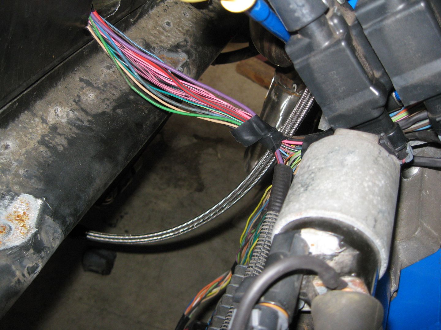
Hopefully on Sunday I will add in the A/C pressure sender and loom up the front harness containing the Alternator, A/C clutch, A/C pressure switch, Ground to engine, B1 Knock, Fiero Oil pressure sender and finish up the engine side of things. The wire bundle across the exhaust manifold is the portion of the harness that will enter the center console area (500, 203, TCM and A/C & fuel relay will all be in the center console area). I still need to add in the wires for the throttle pedal, brake booster sensor and the ones to the TCM.
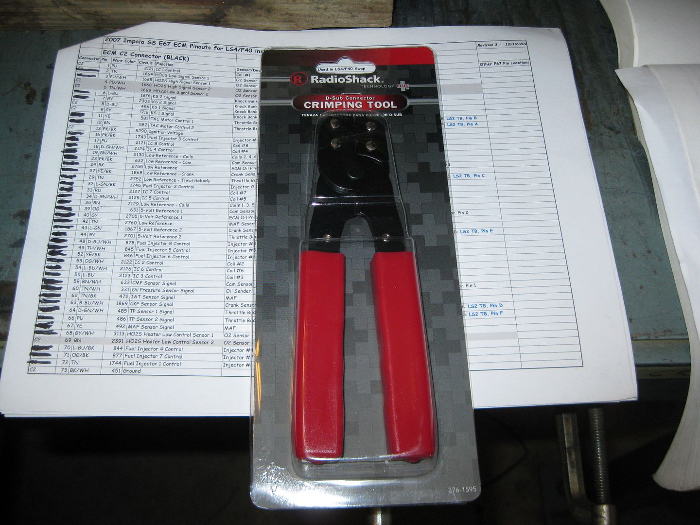
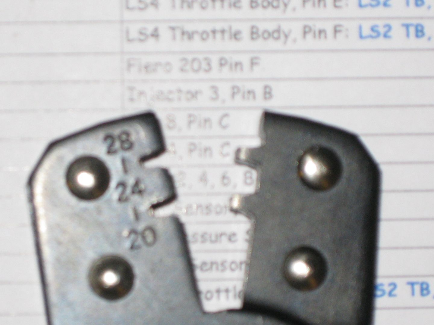
Re-pinning the terminals at the ECM takes a special crimp tool. The professional version costs about $300, The one from LSxTune is about $32, http://www.lsxtune.com/shop..._170/products_id/362 This one from radio shack is $9.99 and the one I have been using so far (ordered the LSxTune one as well):
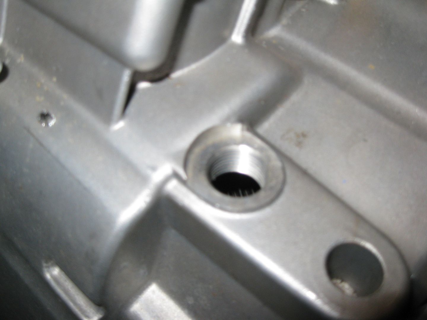
I also found on the truck forum where they were tricking the T42 TCM's shift solenoids with a 1K resistor when swapping in a 4T80 (it had 1 less shift solenoid) so that is promising. They also had other swaps with the T42 TCM where they swapped in a transmission w/o the ISS sensor and were able to tune it out. I still need to check on some things. I may add a 2nd VSS sensor to the transmission and point it at the output shaft gear (22 tooth pinion that drives the 78 tooth ring gear). The 22 would be close to the 25 the TCM is looking for and may be close enough to make adjustments in the tune. Now I need to see if there is a good spot on the case to drill through to mount the sensor.
Installed the A/C pressure sender for the ECM. Found a brass fitting with a 1/8 NPT on one end and used a M10-1.5 die to rethread the other end. Then it was a matter of drilling/tapping the high side fitting at the compressor. I coated the threads with JB-Weld before threading them in to help ensure a leak free seal.
With the last engine sensor installed, I finished up the engine harness (except soldering on the starter terminal end):
The center connector on the ECM is now fully compete. The other two still need quite a few wires from the other various components that will be in the console/foot well/brake booster area.
Next step is to reinstall the engine/transmission in the chassis and continue to finalize the wiring, fuel filter location, build the fuel line and mockup the coolant hoses. Then everything will come out again to finalize the engine bay.
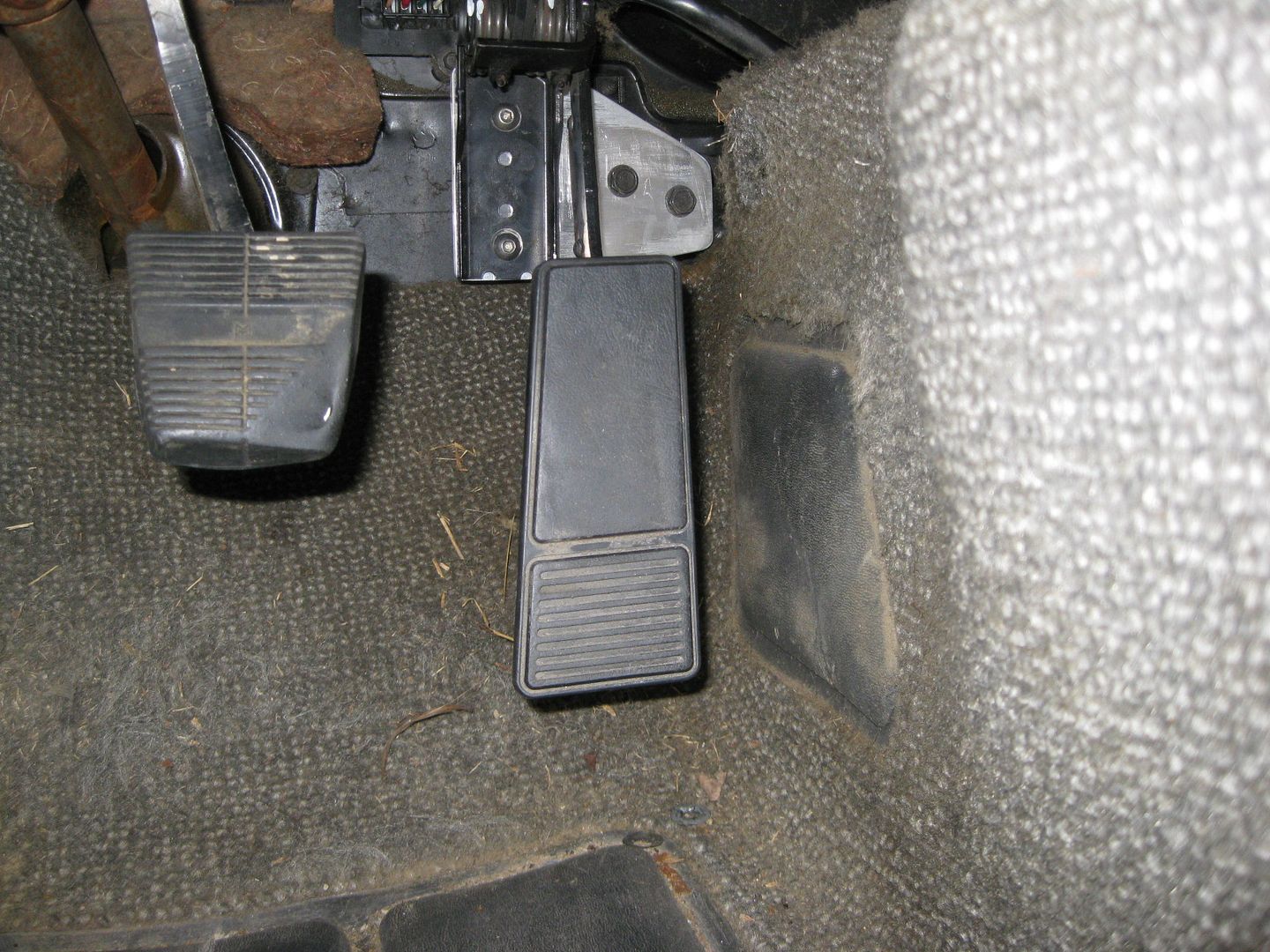
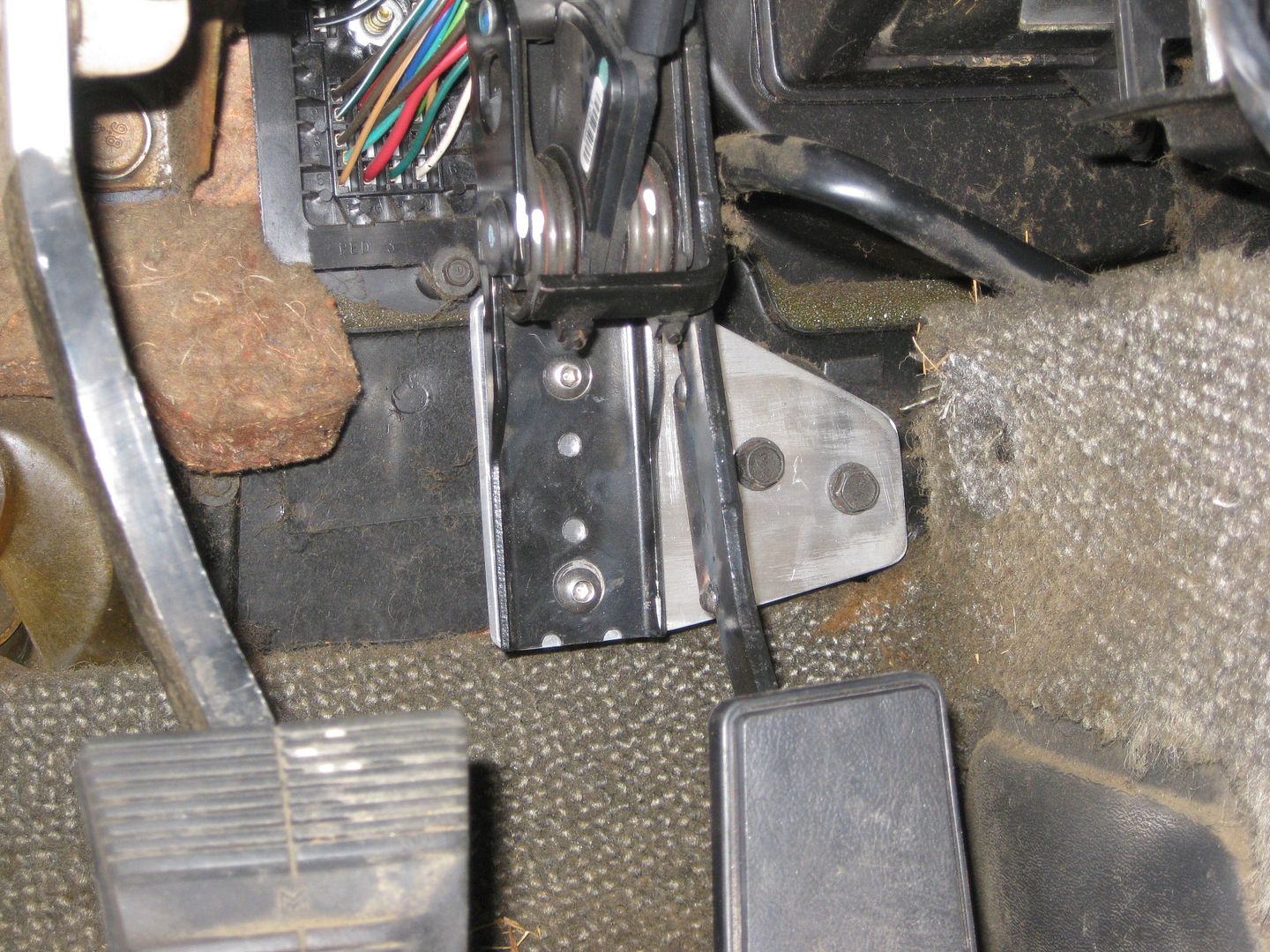
DBW throttle pedal is now installed. I fabbed up an aluminum bracket to mount the pedal to, then the aluminum bracket bolts to the stock fiero pedal mount. This allows the pedal to be slide to the drivers side enough to clear the brake booster vacuum tube. All I need to do for this was remove the plastic mounting block that comes with the throttle pedal (this block is also the primary throttle stop).
Since I removed the primary throttle stop, I welded on a new one. It is just some 3/16" steel the proper thickness welded to the backside of the throttle pedal arm so it will bottom out against the aluminum bracket.
Stock fiero throttle mounting bracket:
DBW pedal installed:
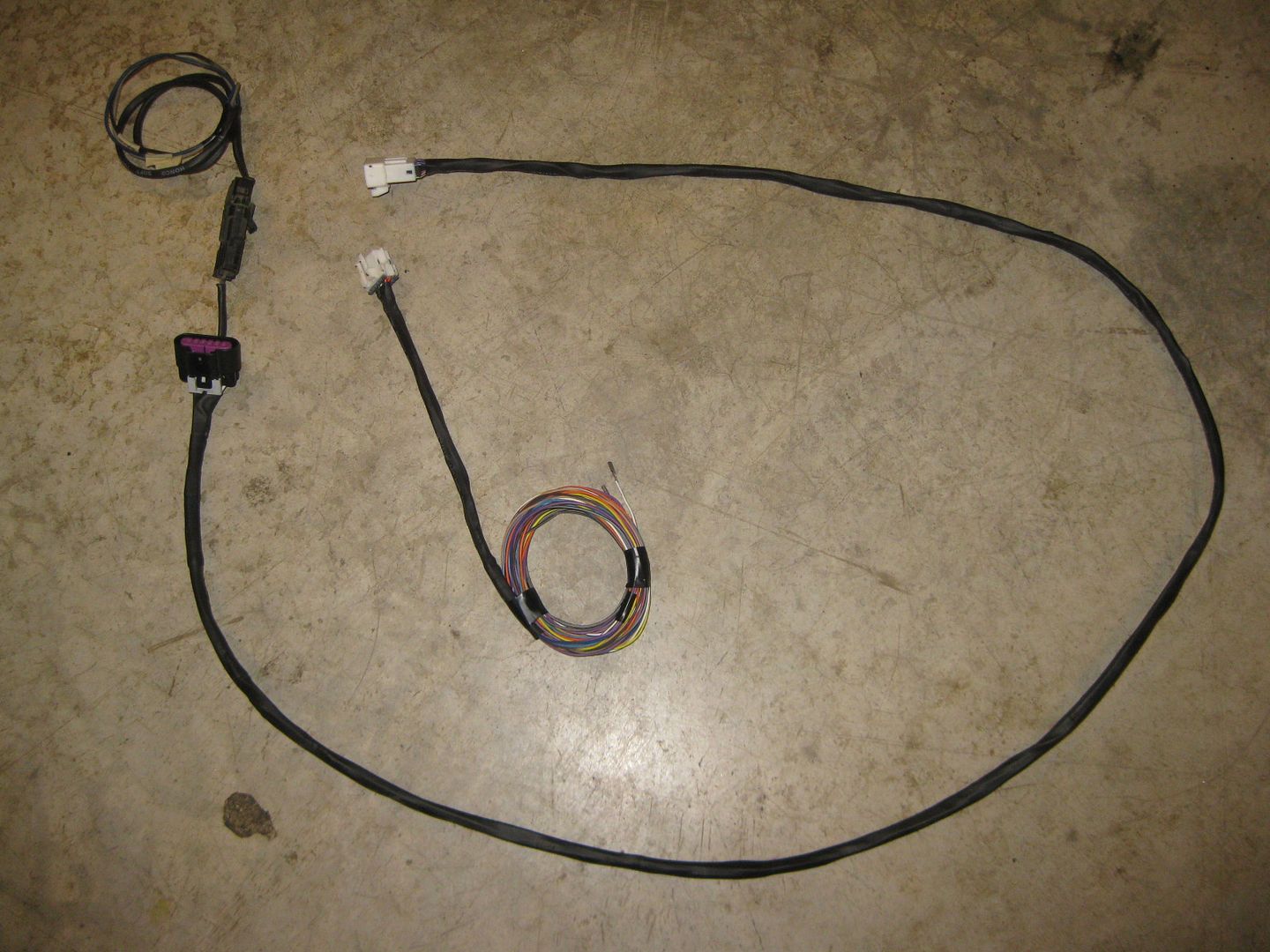
I also started on the interior jumper harness for the DBW pedal and Brake Booster sensor. It will have a 3 wire connector for the booster sensor right by the pedal assy. The other end will have a 10 pin connector (3 wires for sensor, 6 wires for pedal). This way I can removed the interior harness when needed and the engine side will have the other side of the 10 pin connector. Should finish this sub harness up on Sunday.
Finished up the jumper harness for the throttle pedal and the brake booster sensor:
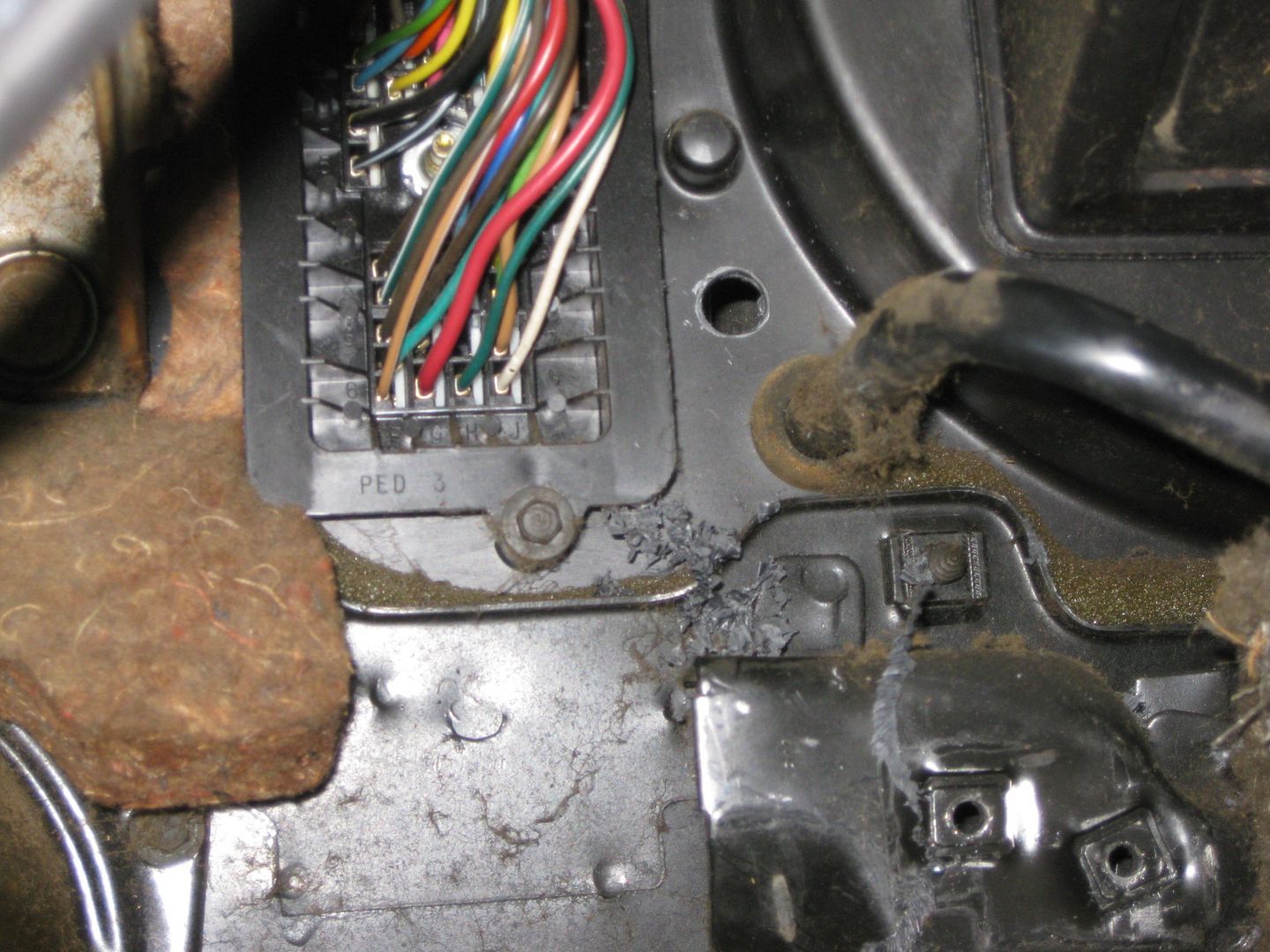
Drilled a hole in the plastic HVAC panel right by the C100 connector for the brake booster harness to pass through:
It is hard to see in this picture, but the harness comes through the firewall and goes under the C100 and under the brake booster to the other side:
Plenty of excess wire for when the sensor is installed in the booster. The raised flat circular surface will be drilled for the new sensor:
Back inside, the pedals were installed again and the jumper harness connected and routed through the center console area:
Also started working on the wiring for the TCM. All the needed resistors to mimic the solenoids and temp sensor as well as the 120 ohm terminator in the GMLAN line were all added in the body of the harness.
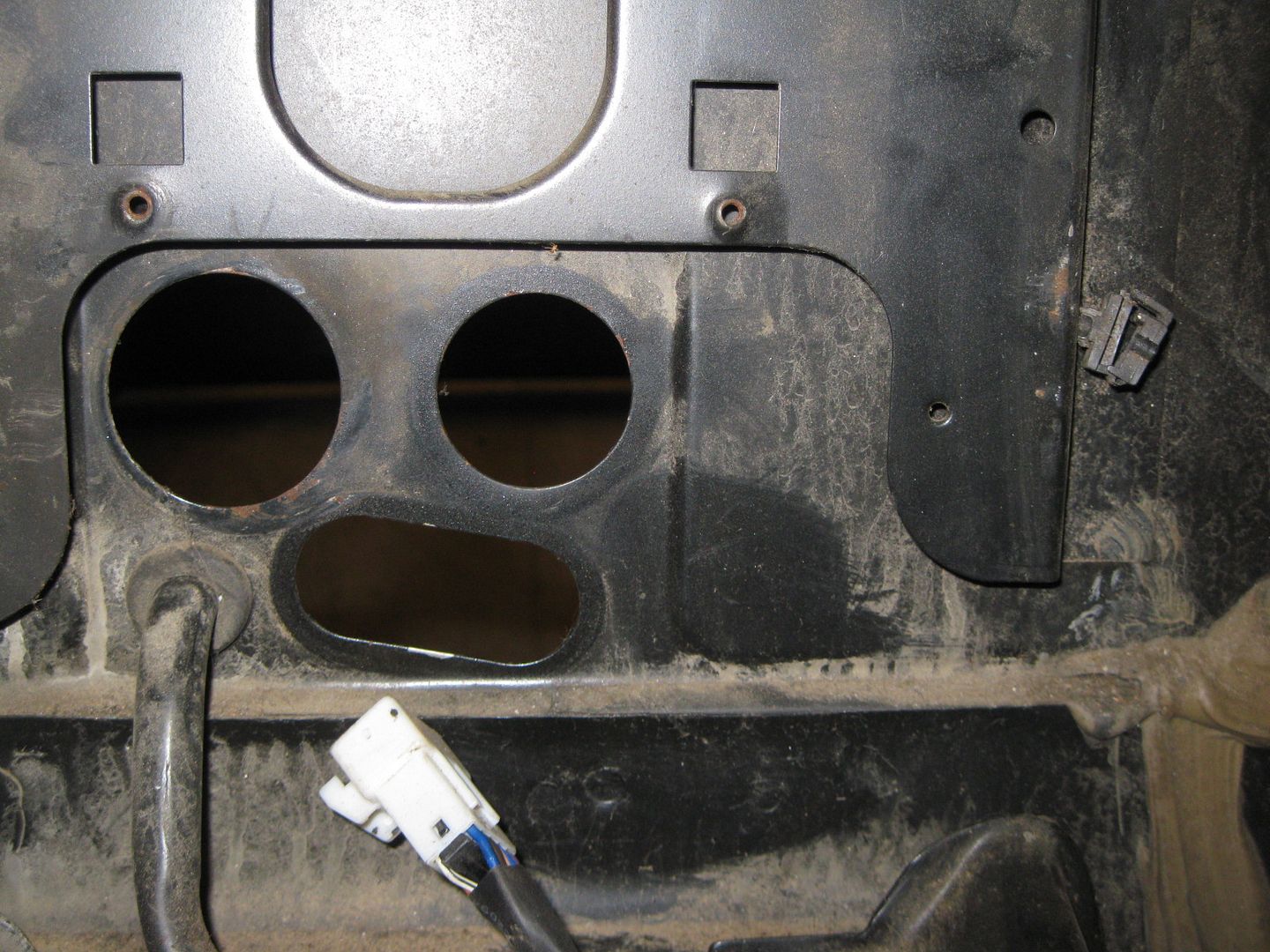
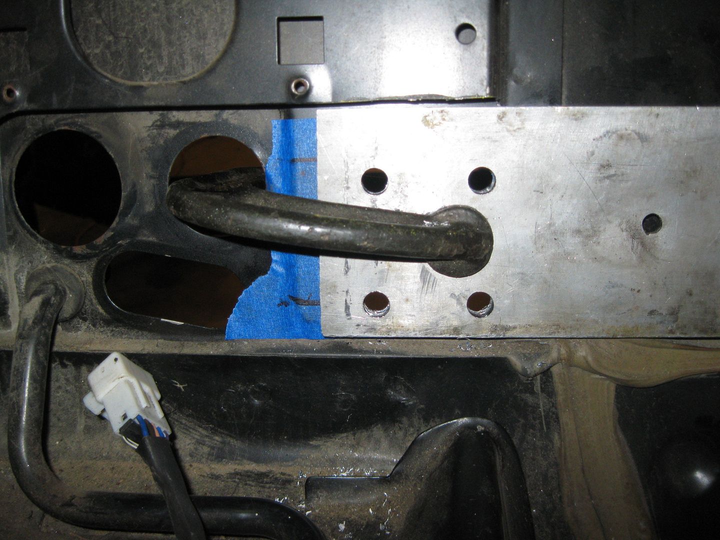
Spent most of the day prepping the chassis wiring... relocating the pass through firewall connector and eliminating the 500 connector.
Here is the stock firewall where the single pass through connector will go:
My drill guide to round the corners of the cutout:
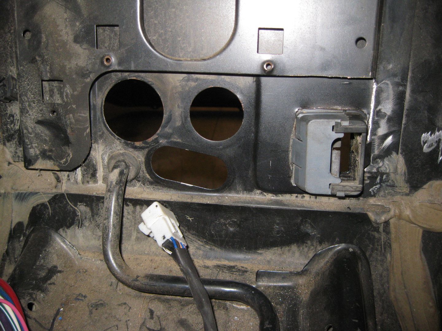
Connector in its new home:
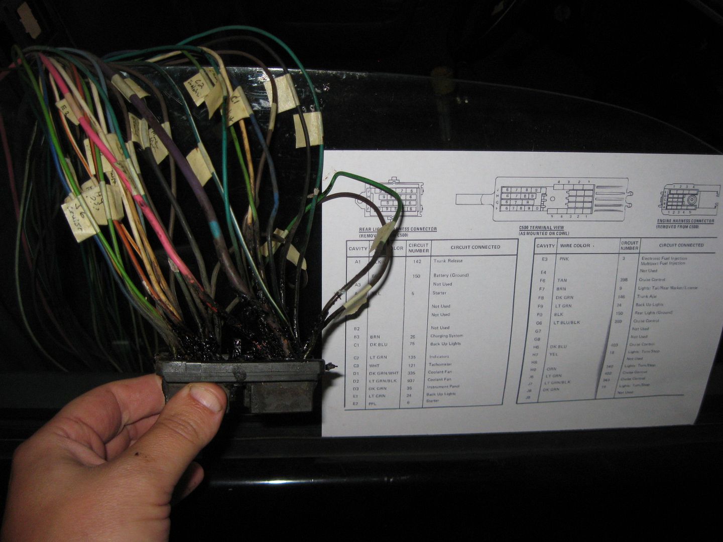
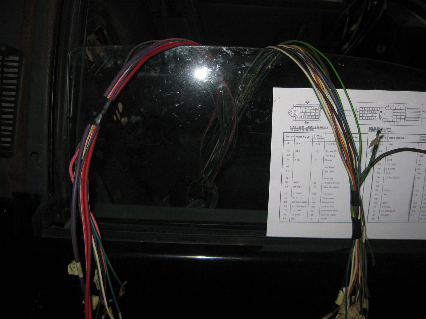
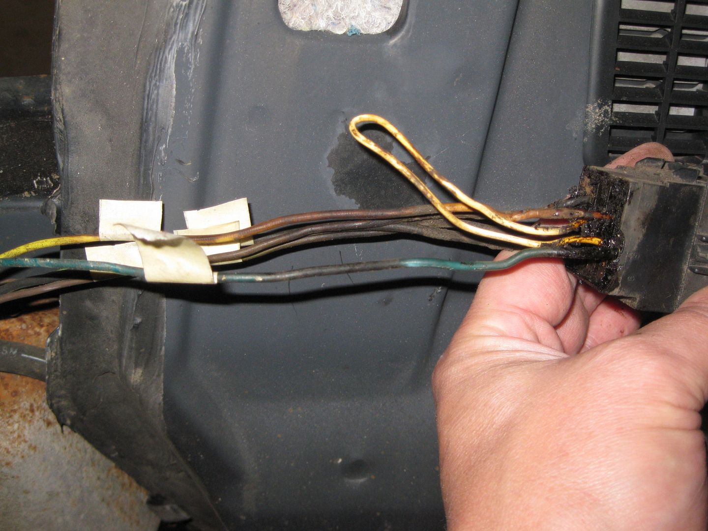
Then it was time to work on the 500 harness and prep it for removing the actual 500 connector:
Once the connector was gone, I separated the wires from engine side to tail light side:
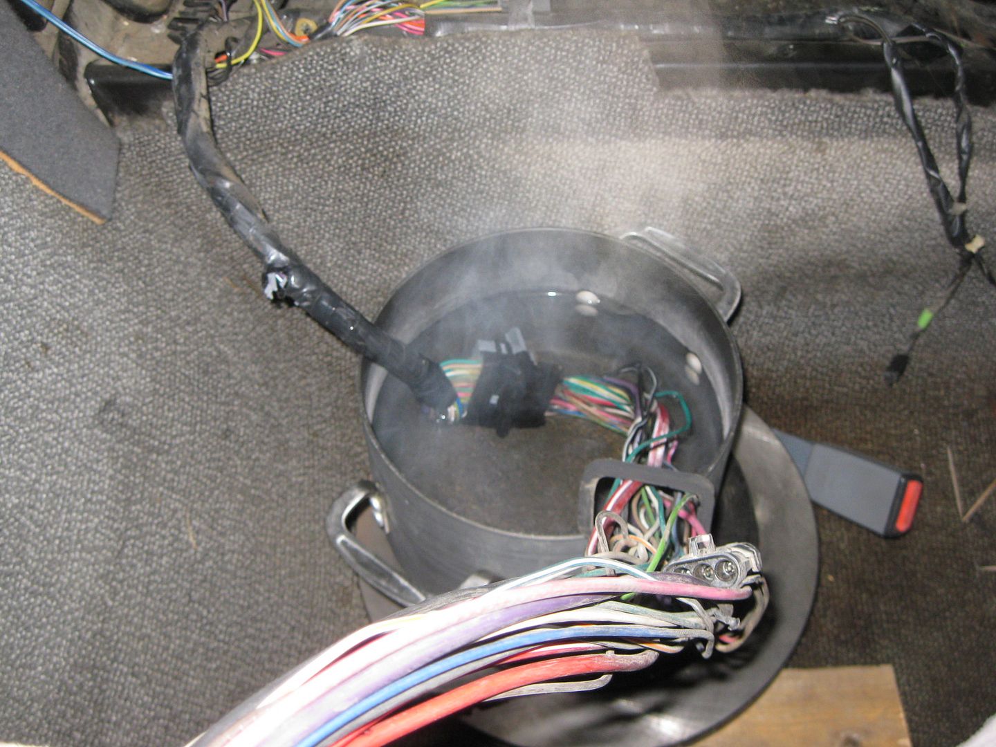
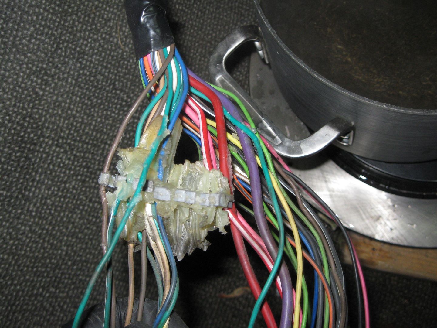
The bulkhead connector on this harness needed to be removed, so boiled some water in a pot and then set it in the car (on a rotor). Soaking the connector for about 5 minutes in hot water softens the glue to the point that is is fairly easy to disassemble the connector:
Did the same to the tail light harness 500 connector:
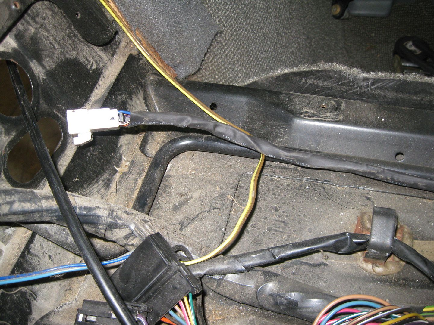
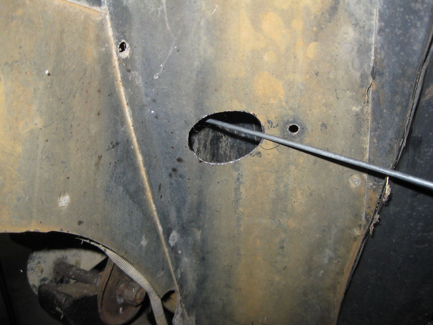
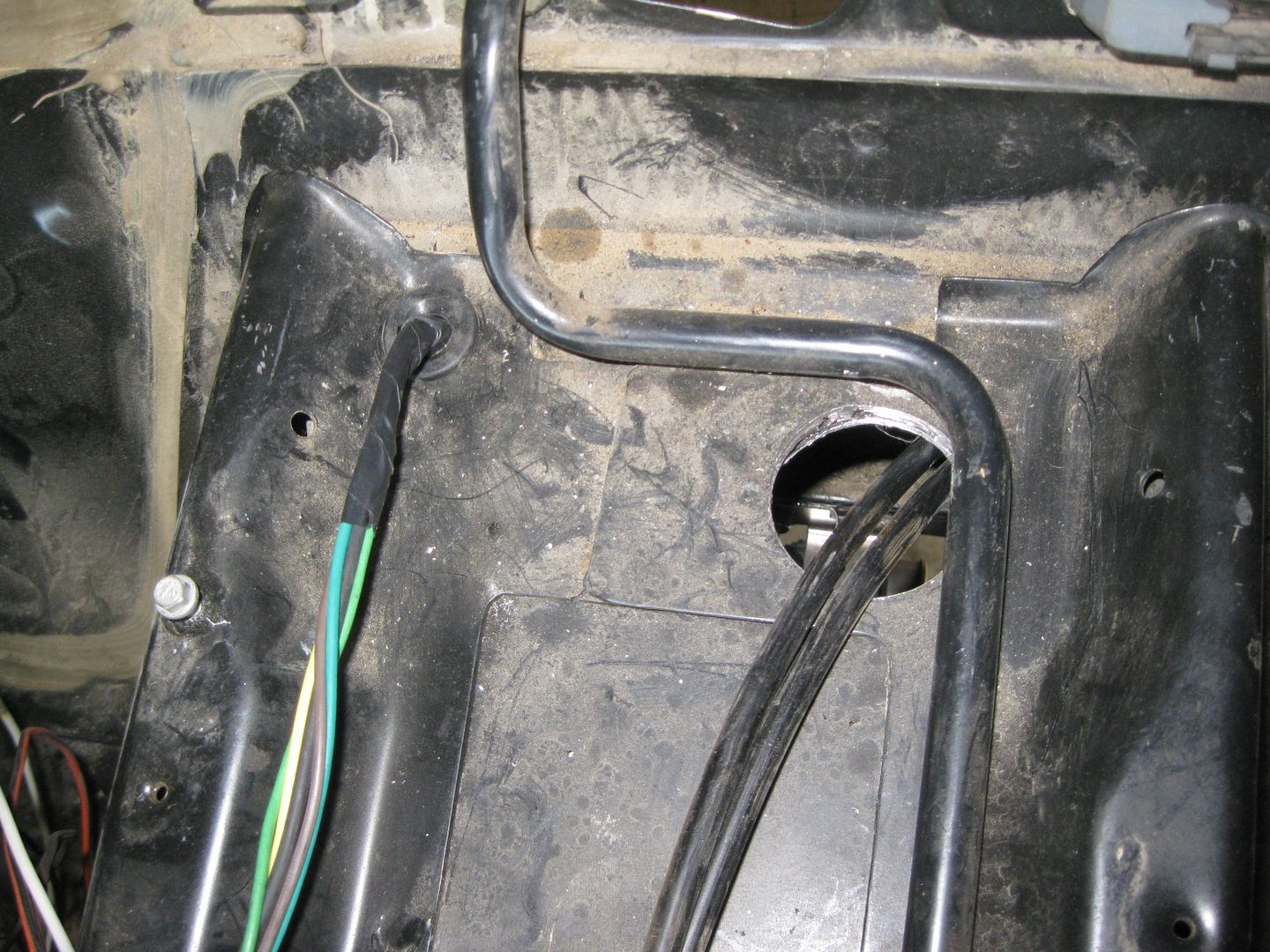
Using a hole saw, I cut through 2 sections of steel below the B-pillar area which gave me access to the double firewall section. I fished a piece of steel rod through there and taped the tail light harness to it. Also drilled a 5/8" hole in the console area to pass the wires into the fuel tank/double firewall section. Tape the wires to the steel rod and pull it back out:
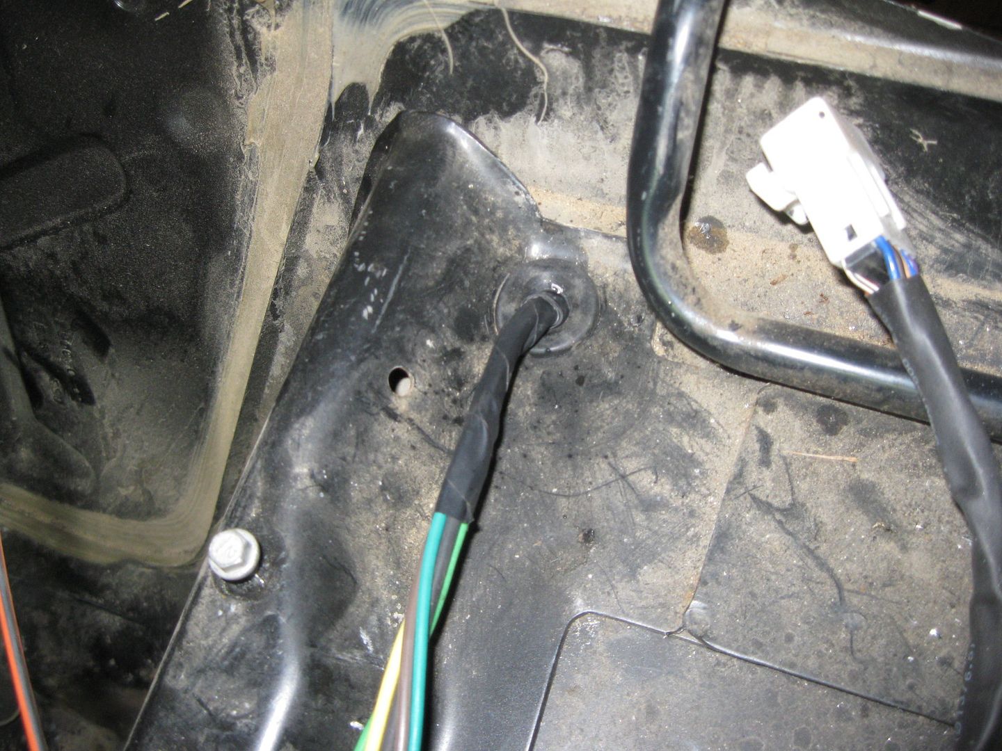
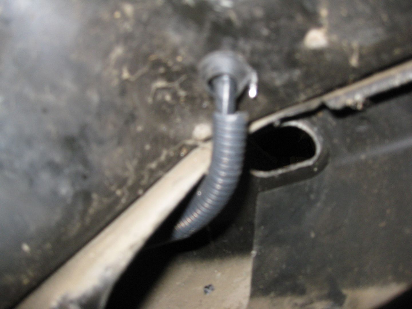
Underside of fuel tank/double firewall area:
The the tail light harness wires were cut to the proper length and splices, soldered, shrink wrapped and loomed:
Wow... at some point, we all need to chip in and get you just a completely mint, stripped down Fiero frame/cradle... and just let you re-engineer the whole thing from the ground up, and sell the new designs to GM. The attention to detail is just that good... always impressive updates man.
Nothing new to report from Sunday to today... spent 3.5 hrs moving the grass for the last time (hopefully) and doing the honey-do list for winterizing. The only thing productive was moving all the removed parts from the 88 to the attic and crawl space so there was room in the garage to walk around.
Not much will happen till this weekend as I am swapped with work. Hopefully this coming weekend the engine/transmission will be back in the car to finish the harness and fuel system plumbing.
Great tip about removing the resin block from the wire bundle that passes through the firewall... boiling it off.
I'm sure I missed it earlier on in your thread, but what's the reason you're keeping the TCM? Is it to avoid reprogramming the stock PCM by fooling it into thinking the automatic tranny is still there?
I'm sure I missed it earlier on in your thread, but what's the reason you're keeping the TCM? Is it to avoid reprogramming the stock PCM by fooling it into thinking the automatic tranny is still there?
I have HP tuner and will be fully tuning the engine for the MAF, Injector, Camshaft and exhaust changes, but there are limitations as to what the tuning packages can manipulate.
Keeping the TCM is all about keeping Displacement on Demand or Active Fuel Management functional. The ECM must see 3 inputs from the TCM to enable DoD and those inputs happen over the GM High Speed LAN... which I can't manipulate. So I kept the TCM to fake the inputs into it so it will send the right signals through the GM LAN... or atleast that is how I "think" it will work.
If I can't get DoD to work, then I will probably swap out the cam to something more agressive and retrofit the engine to variable cam timing (I started with a Gen 4 engine, so I can swap over the parts and use the same E67 ecm with a different application code pretty easily).
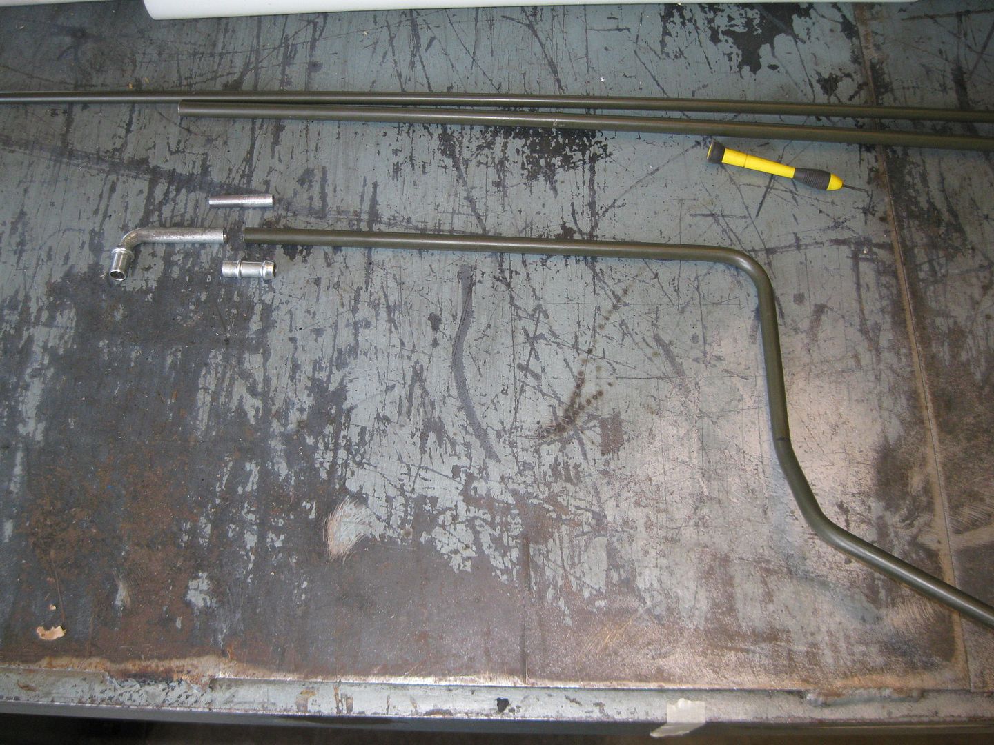
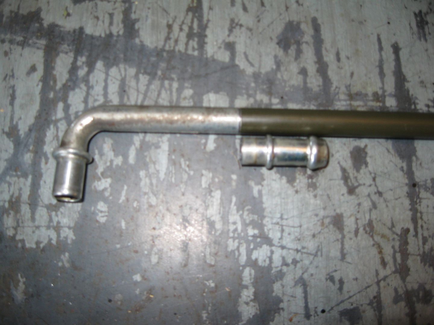
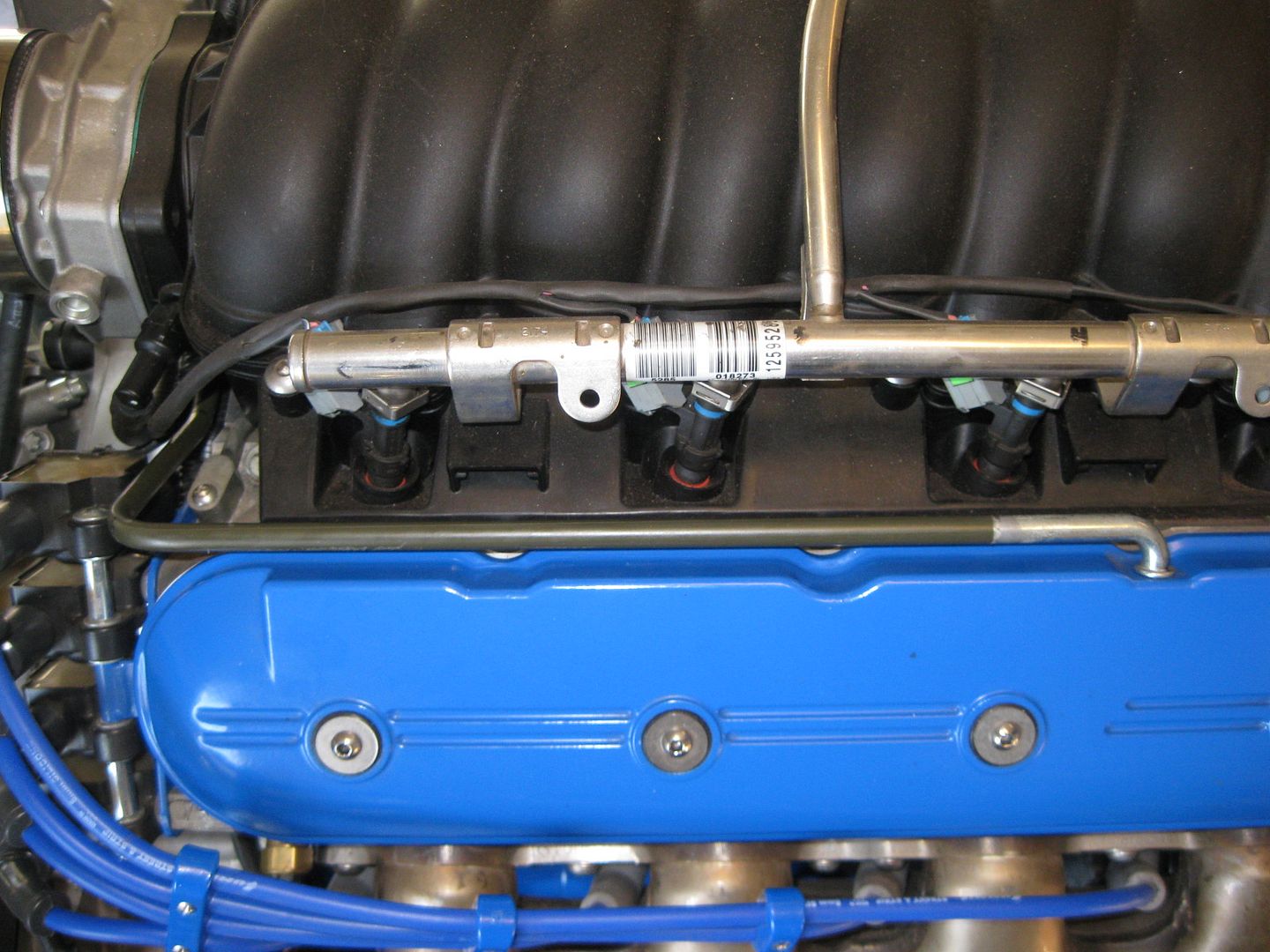
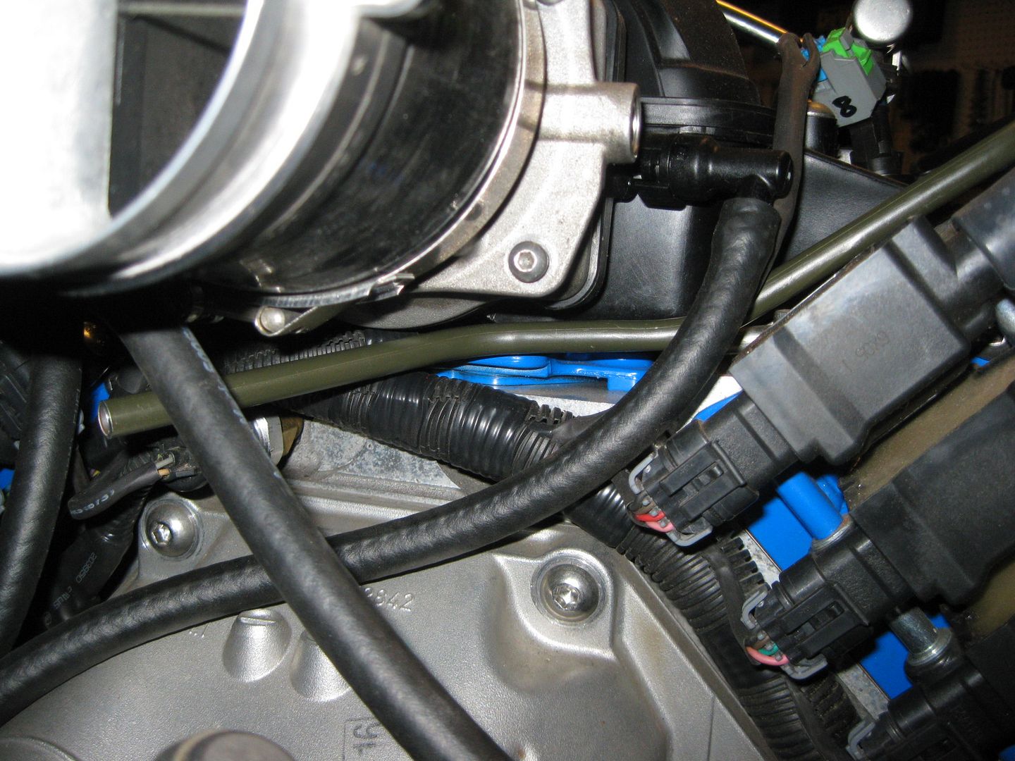
After cleaning up the garage again, I was able to spend a couple of hours working on something that was "done" but I didn't like the looks of it. I wasn't feeling the rubber hose going from the throttle body/maf coupler to the rear valve cover. So I decided to redo it with 3/8" hard steel line. Once it was went into the proper shape, I cut the barb portion off the valve cover end, fabbed up a 5/16" internal tube splice, then silver soldered the valve cover side, and JB welded the other side. I didn't silver solder the other side due to the paint/primer on the tube and I wanted it to have as little movement as possible while setting up.
I am much happier with this setup. Once the tube is painted semi-gloss black it will fade away into the intake manifold. I still need to trim the end at the throttle body and run a short section of hose to connect it.
I spent an hour working on the thread-in nipple/washer to raise the vent, but I was too aggressive with the feed speed on the lathe and broke it. I have a new one to start over with, but that will have to wait till Sunday.
I finished the fuel tank vent mod which should get me .6 gallon increase in usable capacity.
Soldered on the terminal for the battery cable at the starter:
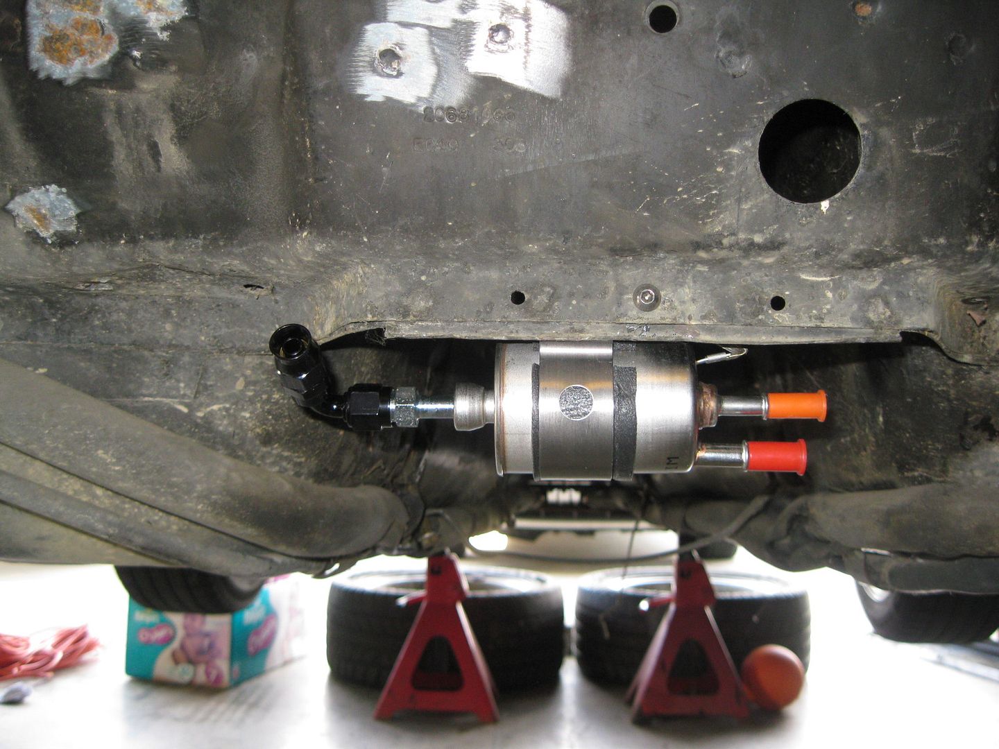
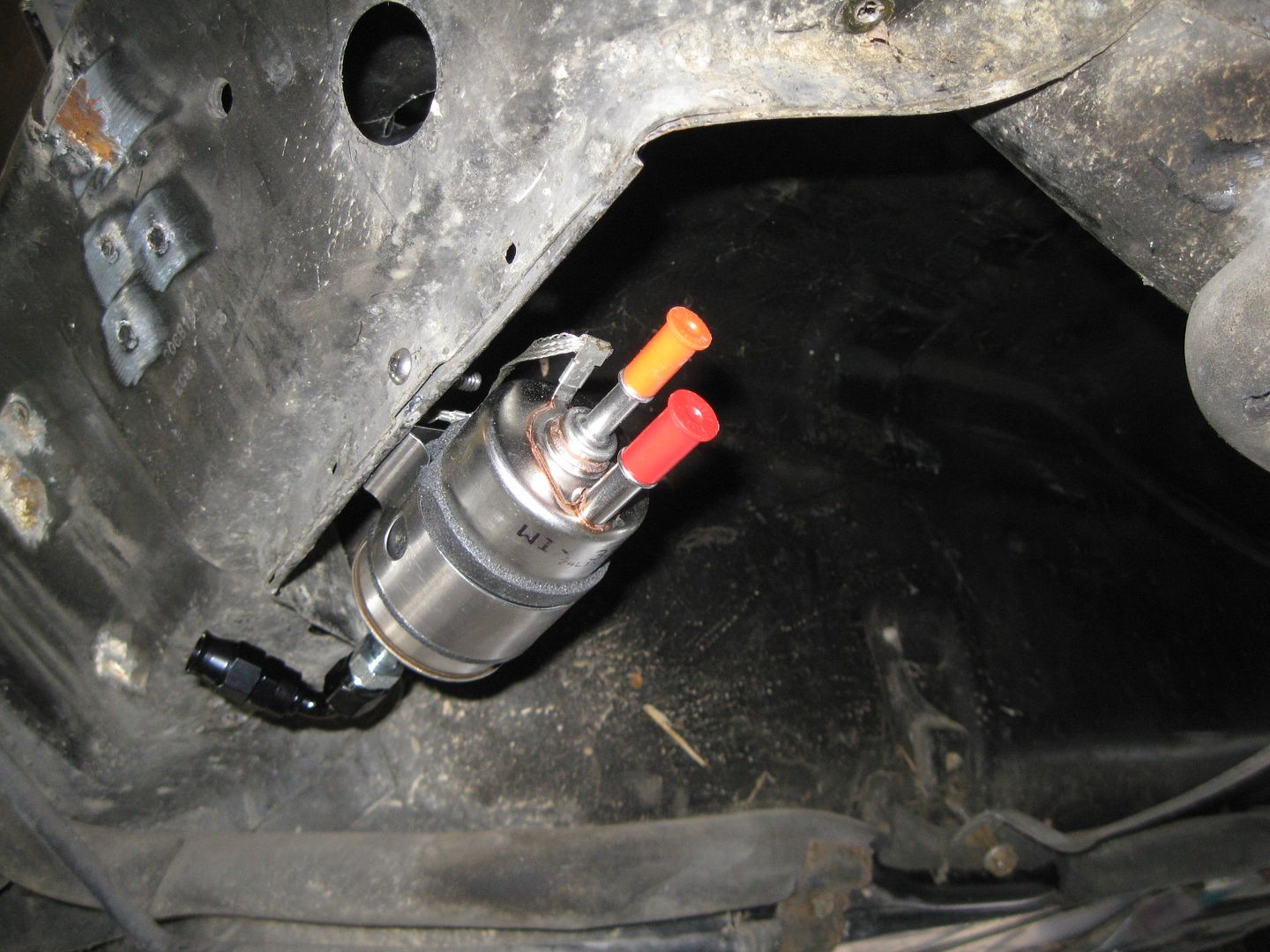
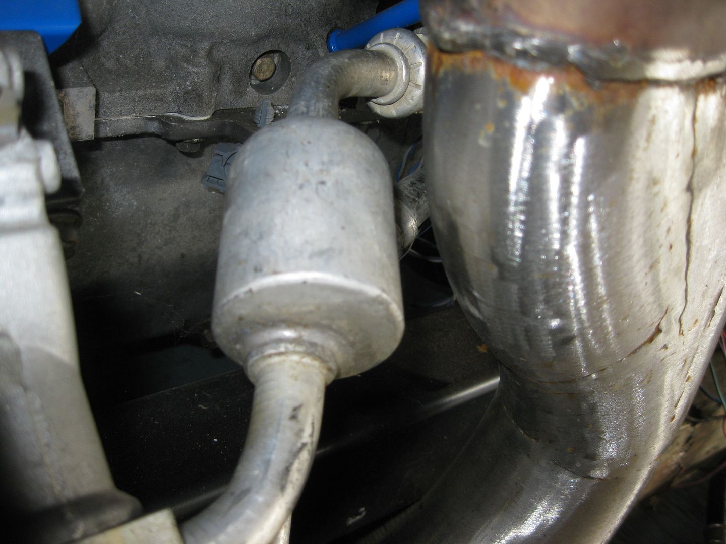
Mounted the fuel filter (I slid the bracket that comes with it off and flipped it around):
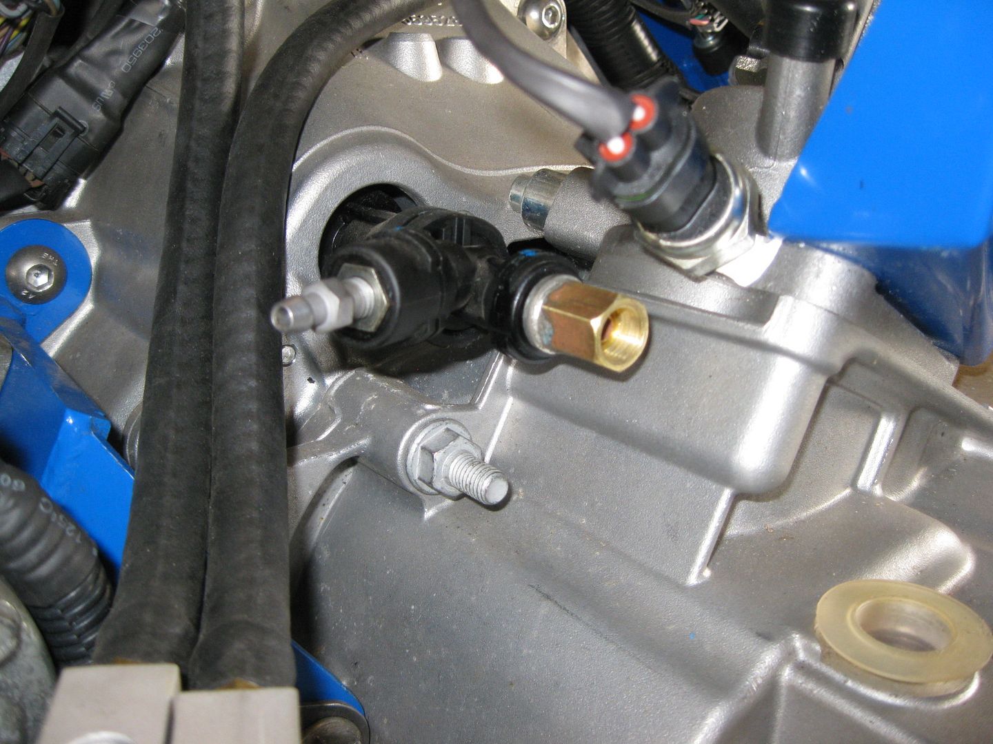
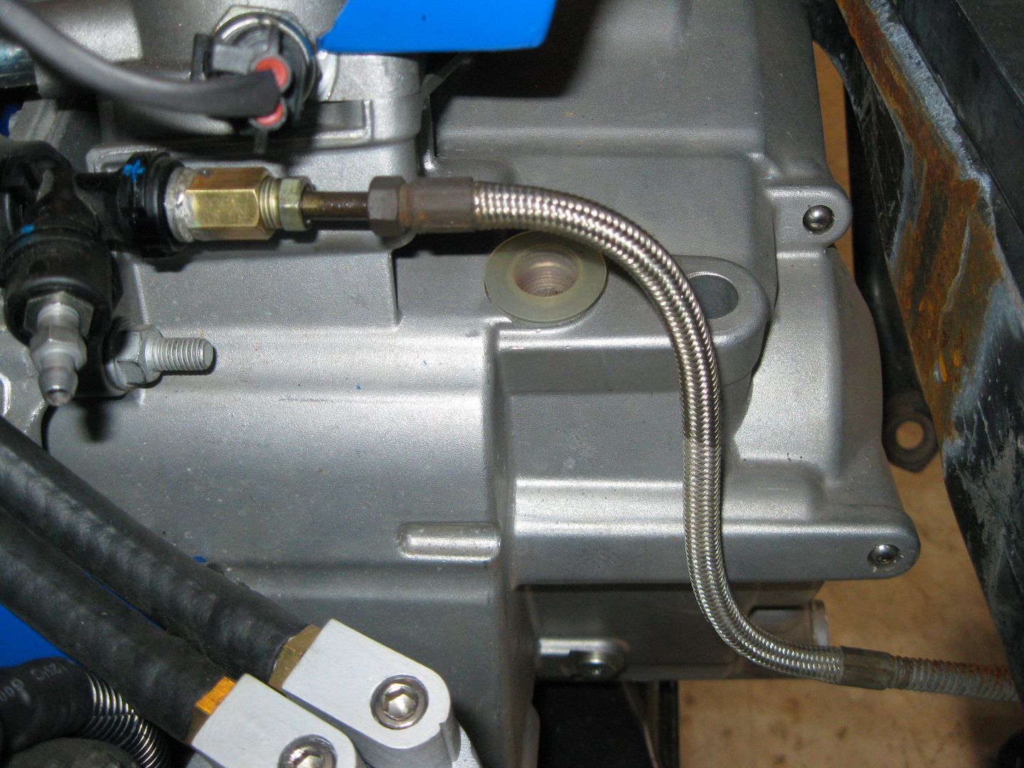
Took apart the G6 clutch master/bleeder assy and modified it to take a traditional flared line. Machined both pieces for a press fit then silver soldered them together:
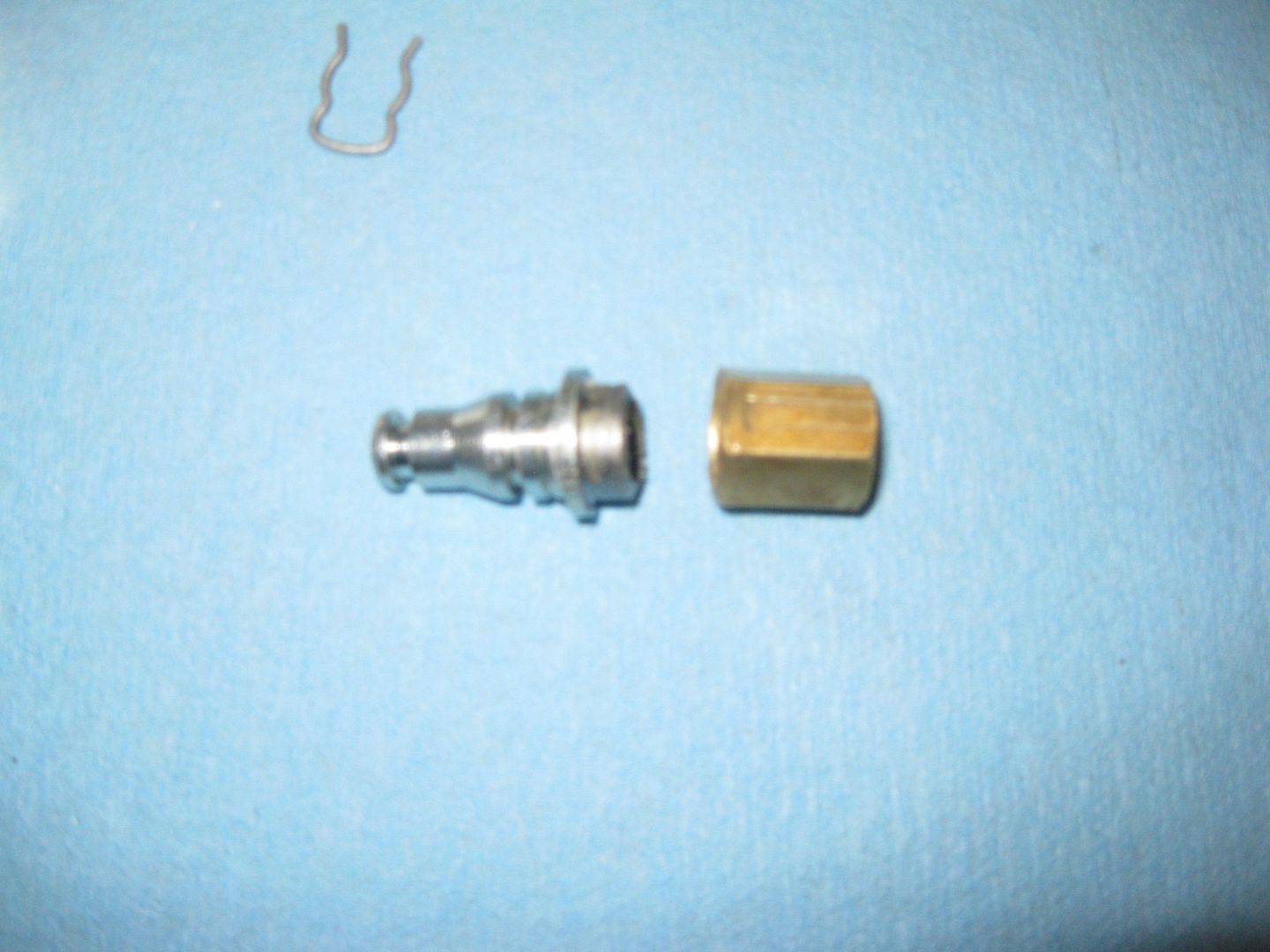
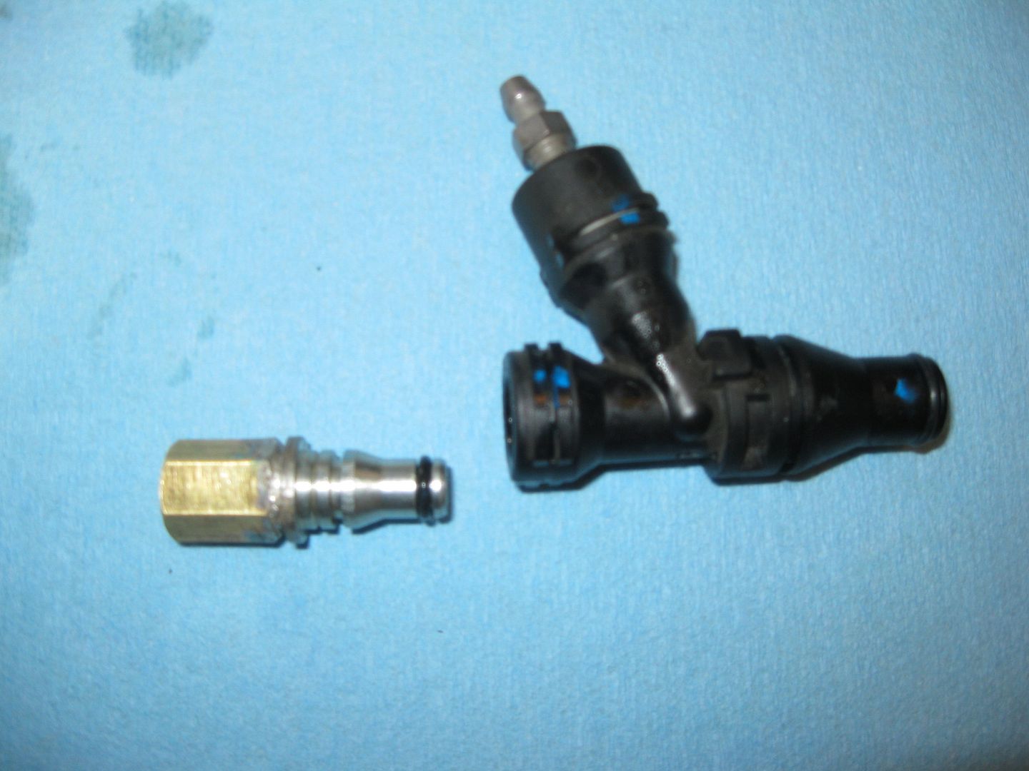
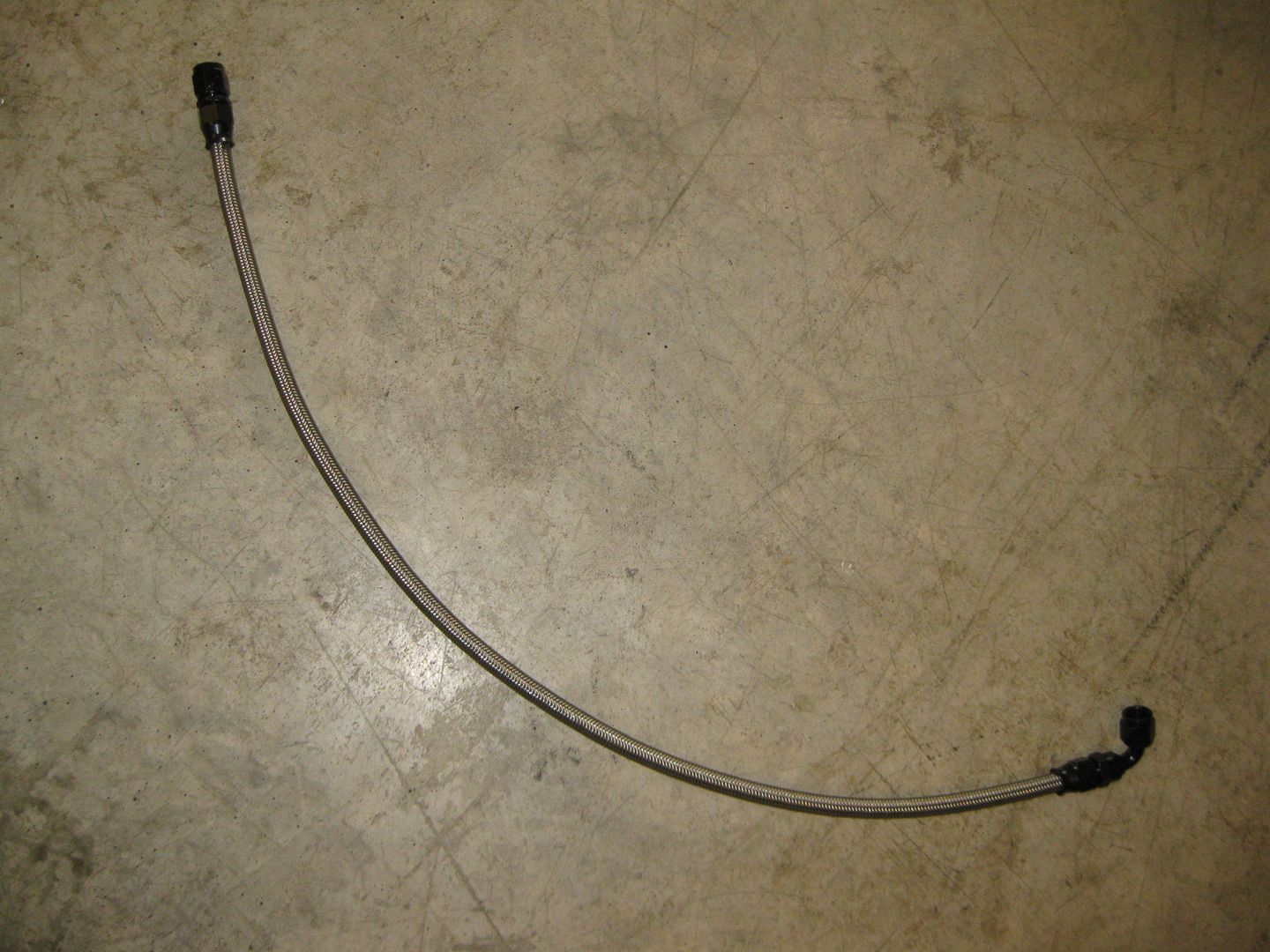
Since the engine was put back in place for the wiring, I also took the opportunity to make the fuel hose:
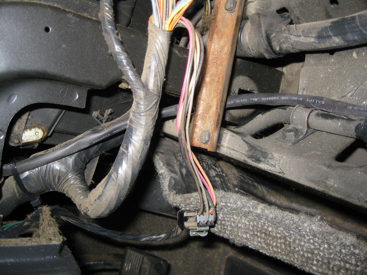
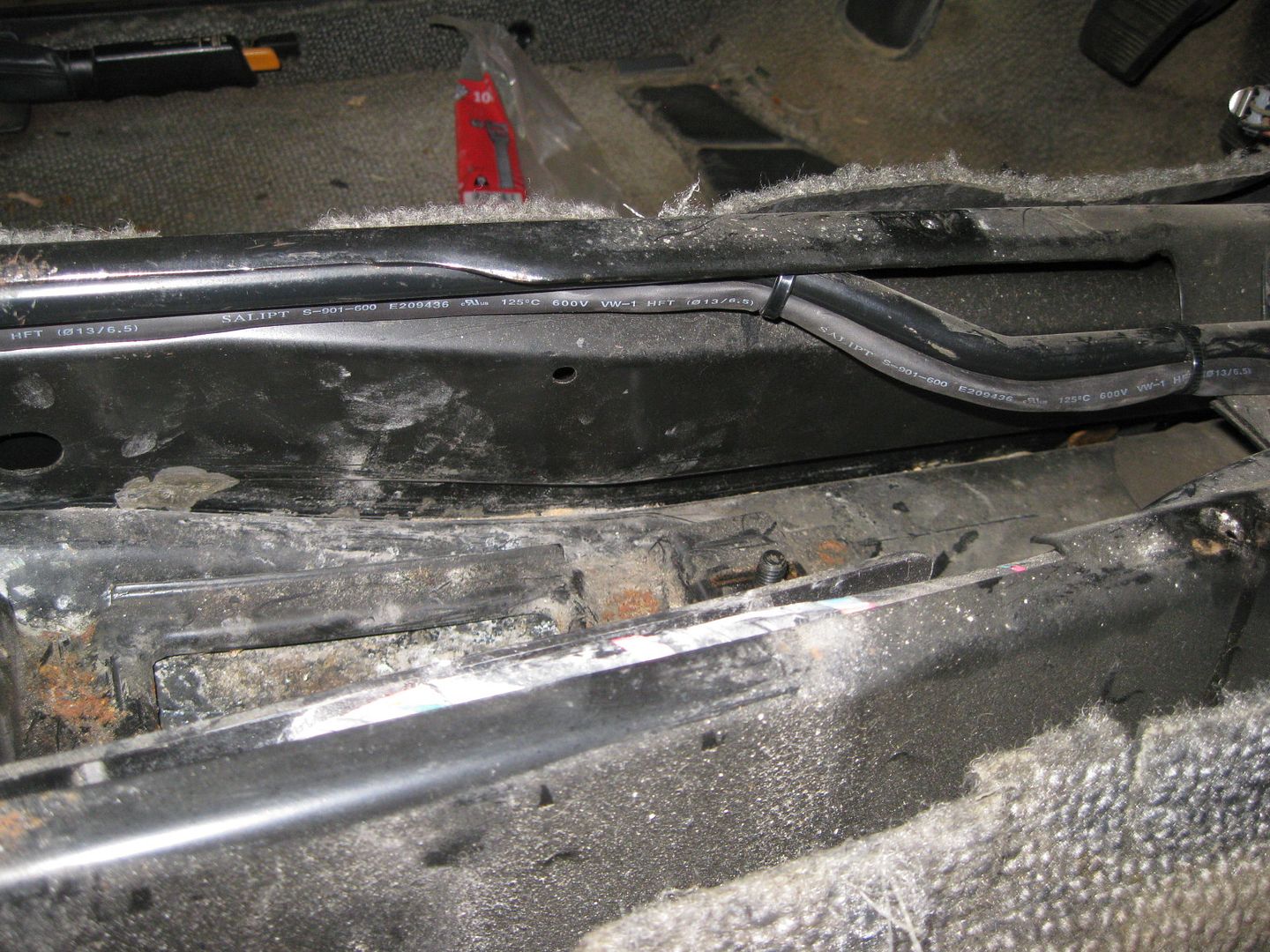
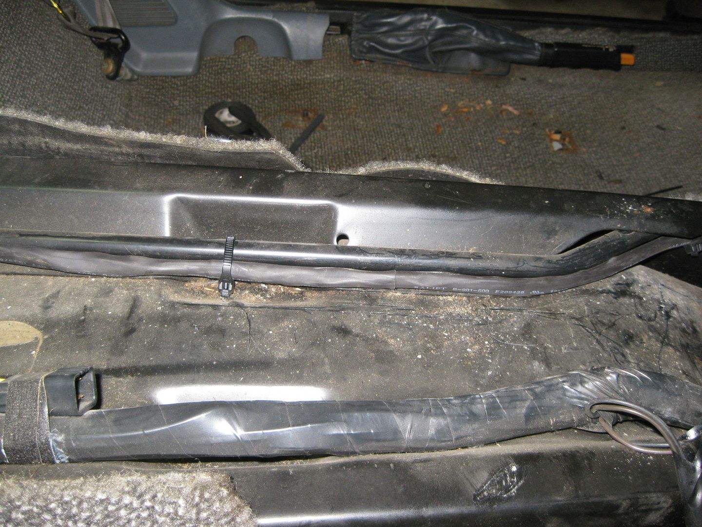
I wanted to keep the shifter cables as far from heat as possible, so I routed them down into the double firewall section and out by the fuel fill tubes. I will probably remove the insulation on them.
Here are some overall pics:
While the engine is in place, I need to finish the wiring harness, coolant connections, A/C hoses and fabricate a cold air intake (the GM truck one doesn't quite fit and I don't want to cut it up and have more couplers, I will get some exhaust tubing and weld something up). Then it will come back out to finish all the detail work in the engine bay.
Man that is just inspiring to see how efficiently you tackle things (and the cool stuff you fabricate up to make it 'cleaner'), and keep everything else that needs to be done in mind. For what I've done myself or helped others do, I can't count the number of times we'd finish and go "damn, forgot to do c while taking care of y."
Man that is just inspiring to see how efficiently you tackle things (and the cool stuff you fabricate up to make it 'cleaner'), and keep everything else that needs to be done in mind. For what I've done myself or helped others do, I can't count the number of times we'd finish and go "damn, forgot to do c while taking care of y."
Thanks! Most of what I do just takes pre-planning (the actual work isn't to difficult) and given that I have been working on this swap off and on for 2 years... I have had a lot of time to think about how I wanted everything. The more swaps you do, the more you focus on the finishing touches... a nice clean install can become overly cluttered in the final installation stage if you haven't planned for how everything that must be connected (harness, hoses, lines, etc) up will flow with everything else. If I don't like the way something I have done looks, then I will take the time to redo it.
The only part of the swap I am still not feeling is the water pump and its fill point, but for the sake of actually getting this car running, I am leaving it as is for now. Eventually I will make a one off mechanical water pump to replace the one that is there now.
[This message has been edited by fieroguru (edited 11-12-2012).]
Is there a reason for going with a mechanical one over an electric one? To me, I've thought that electric pumps had quite a few more "pros" to them, but perspective is everything.
Is there a reason for going with a mechanical one over an electric one? To me, I've thought that electric pumps had quite a few more "pros" to them, but perspective is everything.
It is a personal preference on multiple fronts. The ones I have used, worked on, or driven in the past were all loud enough to hear in the passenger compartment (far worse than the stock fuel pumps), I prefer the whisper quiet of a mechanical pump so I can hear the engine sounds... not pump whine. Since most electrical pumps won't fit on the engine, so they add hoses, wires and other clutter and generally look like an afterthought to me. With the LS engine the remote water pump also requires a remote thermostat housings which adds even more hoses and clutter. Lastly, I think a creative/custom mechanical water pump setup adds to the overall swap package, especially when one doesn't normally fit.
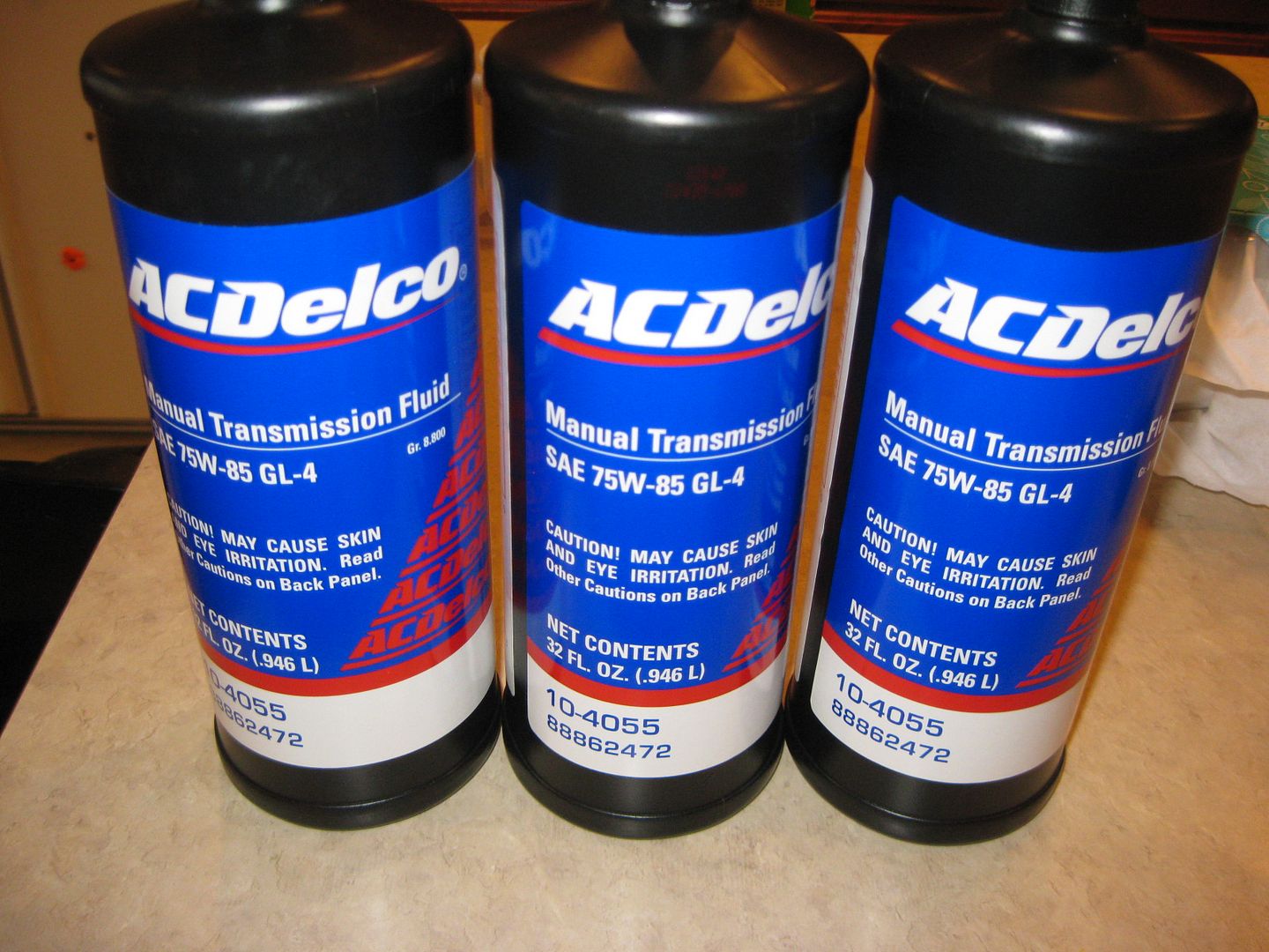
In another thread someone was saying that the special transmission fluid/gear oil for the F40 was hard to get. The GM part # is 88862472 and I purchased 3 quarts from www.CrateEngineDepot.com for $72.70 shipped. Definitely not the cheapest transmission fluid, but I figured I would start with the GM fluid first.
It shipped the same day and arrived today (from IL). The capacity was revised from 3 liters to 2.2 - 2.3 liters.


 I must've missed where you got it from. Is there some kind of sight gauge on it to let you know it's full?