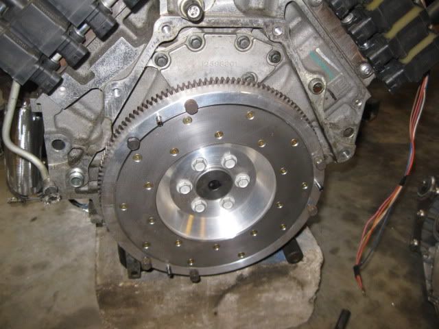
Could I ask what your material costs for the flywheel were in total?
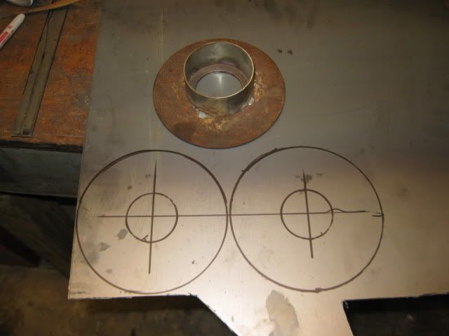
The materials cost was $160.63 for the aluminum, wear strip and ring gear.
I scored the aluminum 2 1/8" thick, 12" disk on ebay for under $100 shipped, the friction surface also came from ebay for $50 shipped and the ring gear was about $16 shipped from Amazon (wife is a Amazon Prime member = free shipping).
[This message has been edited by fieroguru (edited 04-07-2011).]
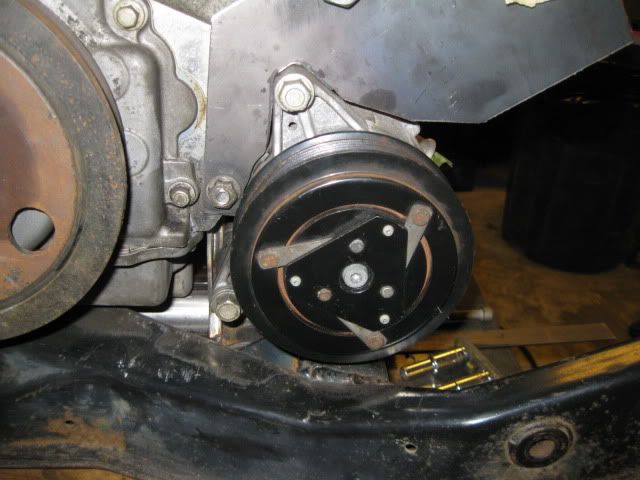
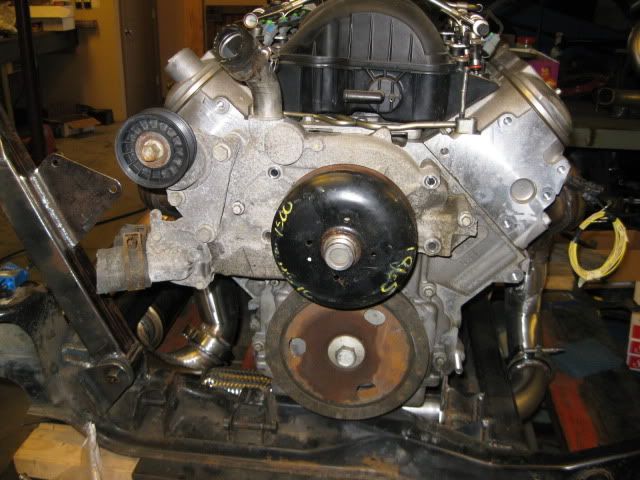
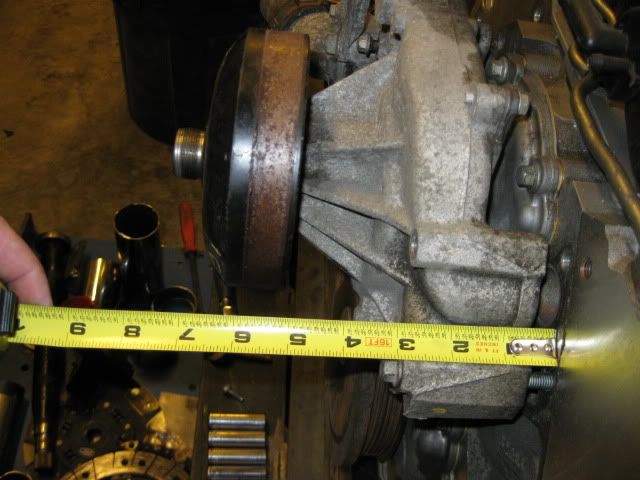
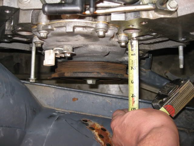
[Sidetrack] I came across a truck water pump for $5 + shipping and was curious how it would interfere, and since I haven't seen these before in any of the other LS4 threads I decided to share them here.
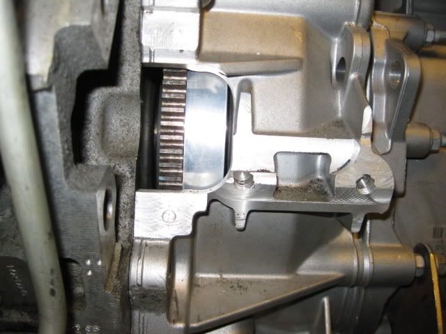
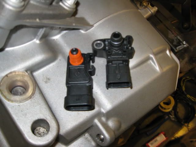
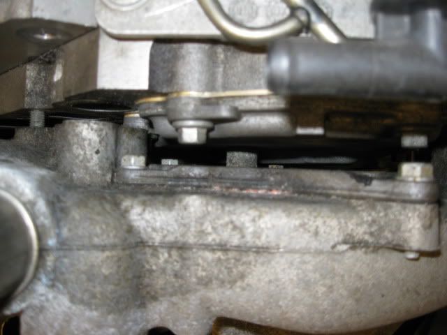
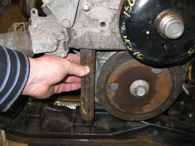
I needed to disconnect the rear engine mount to slide the water pump in place... the engine moved less than 1/16" with the 3 other mounts holding it in place. I also had to remove the cam sensor since this water pump sits right on top of the sensor hole. After those two parts are removed, the water pump then hits the bolt boss for the cam sensor and keeps the water pump about 1/4" to 3/8" from the block face. If you were to mill down the boss and clearance the timing cover slightly, then the water pump would sit flat, but I an not sure the cam sensor would ever clear the water pump (maybe it could be notched, or you could switch the the RWD timing cover... but then you may need to switch ecm calibrations and you might lose DoD):
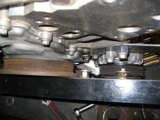
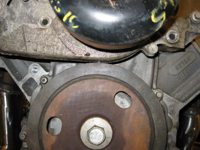
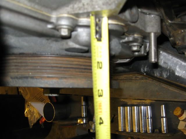
There is about 1/16" between the balancer and the bottom of the water pump... not a show stopper since you can't use the LS4 balancer anyway:
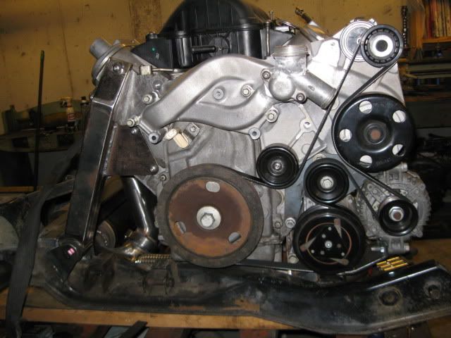
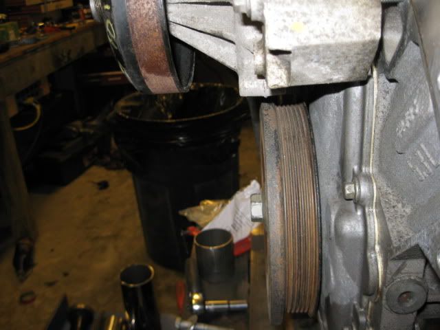
Side profile shot to show the relative depths of the balancer and the water pump pulley. Granted the Camaro/Vette pumps have the deeper pulleys, but the LS4 balancer protrudes about 2 3/4" from the block face and the RWD water pump body when mounted flat against the block protrudes about 2 3/4" as well. So the outer edge of the belt driver will be in the 3 3/4 to 4" range from the face of the engine, which is beyond the capabilities of the LS4 balancer... so it would need to be replaced with a RWD balancer.
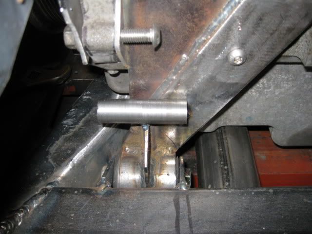
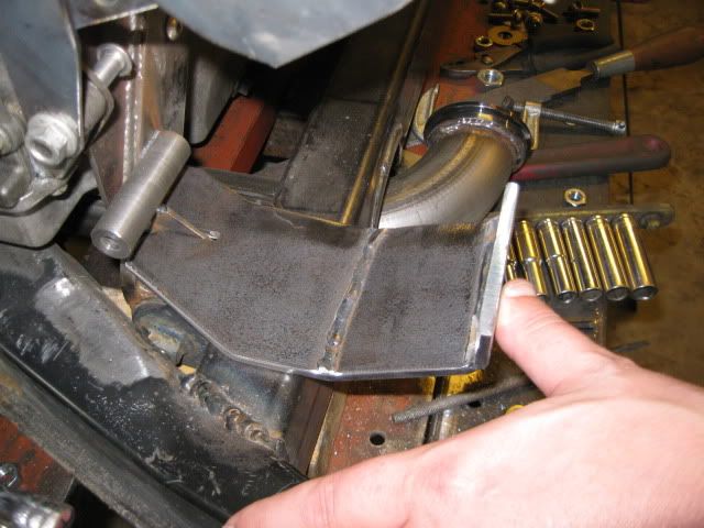
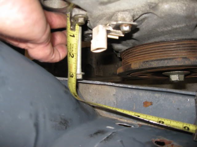
One of the larger challenges is the thermostat housing that protrudes out even further right where the frame rail is pinching in. What I was pondering is just cutting the entire left side of the pump off after the mounting bolts/engine coolant passage and then welding on a new pump inlet that went down and under the balancer to the passenger side coolant tube. They you would also need to weld a thermostat housing to the coolant outlet at the top of the pump. Since the pump protrudes about the same distance as the LS4 balancer, it probably would just barely clear the frame rail... the the pulley is another story.
From the pictures above, if you put the belt drive at 3 3/4" to 4" a frame notch on the passenger side is going to be required... unless you move the drivetrain about 1" to the driver side which will require a frame notch on that side with the F40, but maybe not on other transmissions.
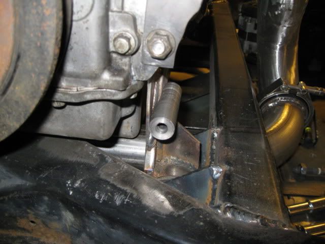
The other thing to take note of is the pump pulley is centered (vertically) between the outer most water pump bolts. With the engine as low as reasonably possible, the top of the frame rail is level with the bottom most water pump bolt. So if the engine was slightly higher a custom pulley could be designed to help it clear a slightly modified frame rail. This pulley would need to have a very small diameter above the frame rail and then enlarge for the belt portion.
So what does this all mean... I think there is a remote possibility that a significantly modified RWD pump could be used for the LS4 application. To do so it would probably be best to mount the engine about 1" higher than mine and about 1" further to the driver side to avoid a passenger side frame notch, but with the F40 you would be notching the driver side, with some of the other transmissions you might be able to avoid the driver side frame notch. Doing this drive-train shift should also allow the drive-train to clear the passenger side deck-lid hinge box. This water pump may require changing the timing cover and cam sensor location as well... and unlike my modified LS4 water pump housing that has a removable water pump insert, the RWD water pumps are replaced as an assembly. So once you modify it, you are locked into using that housing and when the water pump goes out you will either have to repeat the modification process or rebuild your modified housing.
The nice thing with the RWD pump is the modifications to it are probably less extensive than what I did on the LS4 pump housing and you end up with WAY more room to put the AC and Alternator on the front side of the engine. When I get bored or inspired I might start hacking into this RWD pump... but the last thing I need right now are more distractions/delays to finishing my current setup.
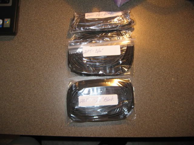
Originally posted by fieroguru: I found a guy on ebay that sells heat shrink tubing on Ebay in 20 foot lengths, so for about $16 shipped I go 20' of 1/8, 3/16 and 1/4.
That's a very good price! Please share your eBay source.
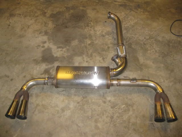
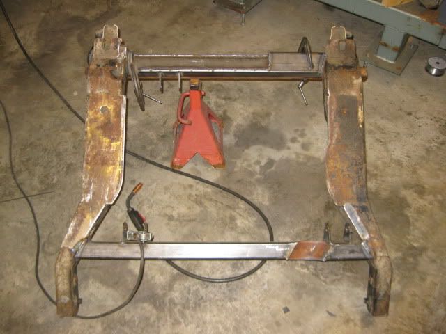
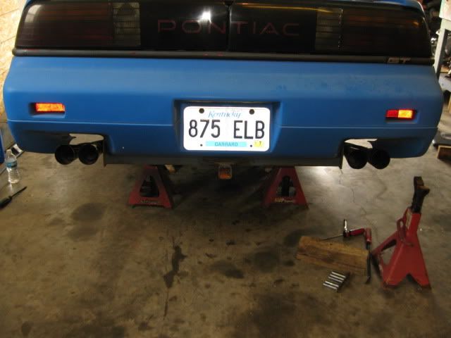
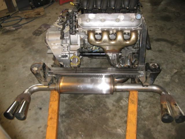
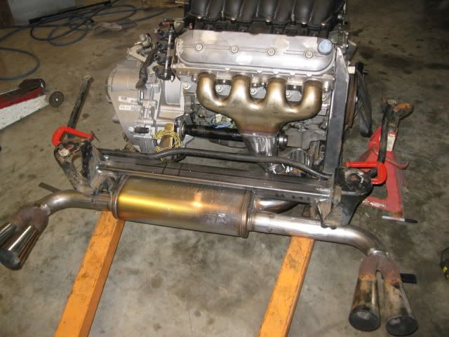
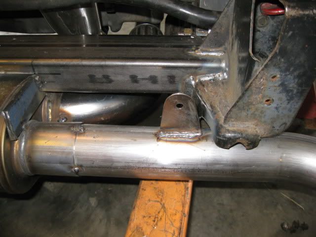
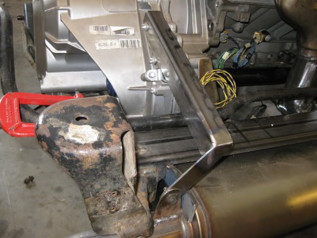
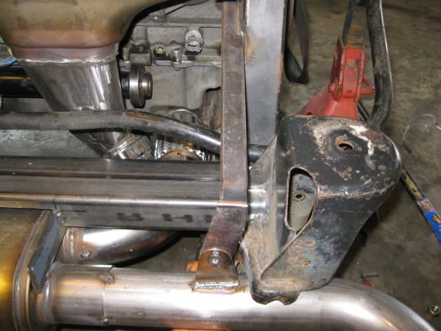
The idea is for the exhaust to rock back and forth with the engine (engine will not move much, but it will move), so I wanted the exhaust hangers to attach to the drivetrain and then cantilever out over the sway bar to support the muffler and tail pipe section. The hangers needed to allow for a slight amount of movement to the rear and to the driver side for thermal expansion, but still solidly hold the muffler/tail pipes.
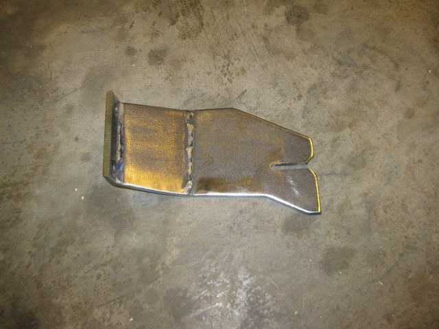
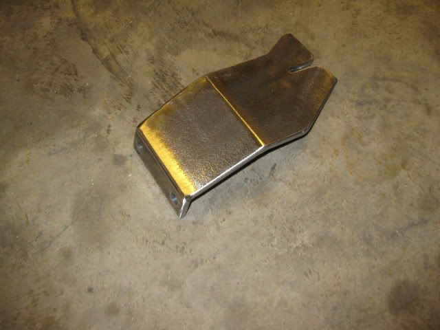
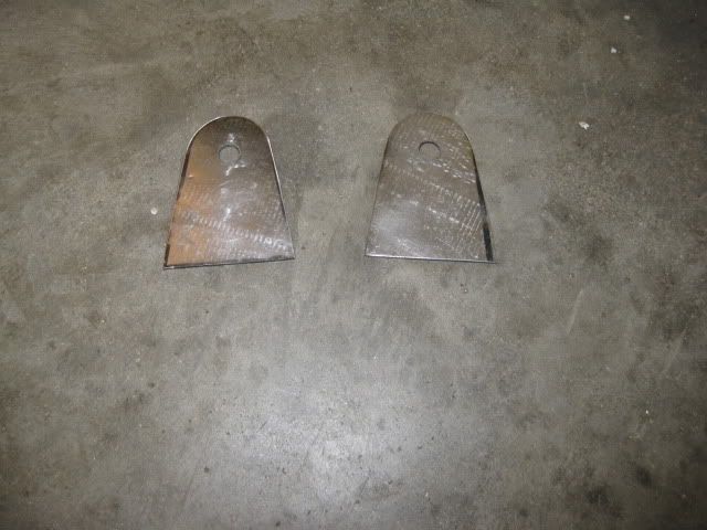
I decided to make some stainless steel hangers from some of the left over exhaust pipe (16ga). Flatten it, cut it to shape and then weld it to the exhaust tubes. The 16ga material should allow some thermal expansion movement.
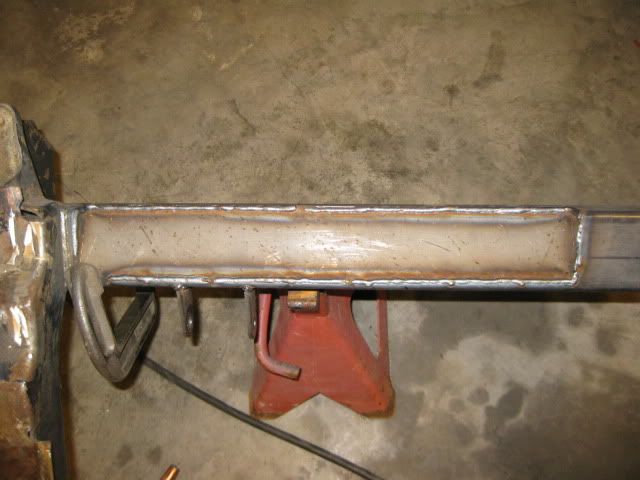
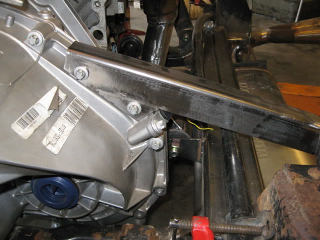
Then it was a matter of making the long brackets that would connect to the drive train. For the tranny side, the transmission case bolts around the differential were in the right general location, so I used them. The material is the "L" section I removed from the rear crossmember for muffler clearance. I did have to weld on a bracket to pickup the 2nd differential bolt and weld on the end piece that will attach to the stainless tabs on the exhaust. Using an angle section on this side will allow the bracket to rotate slightly to accommodate some expansion between the two rear hangers.
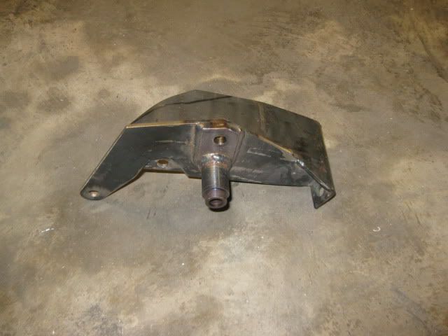
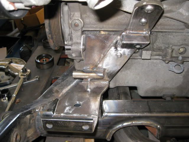
The passenger side one is just some 1x1 square tubing welded to the rear engine mount bracket and the tab welded to the end to connect to the stainless steel tab.
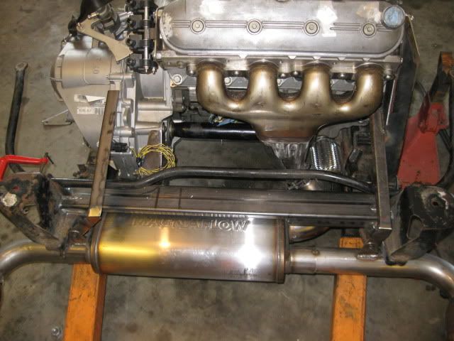
Now I can break the tack welds holding the muffler in place and remove the exhaust for the finish welding. The lower section of the exhaust is held in place with 4 bolts. 1 bolt on each V-band clamps and the 2 bolts at the tail pipe hangers... it will be rather quick to remove this in the future... my old SBC swap had 6 safety wired bolts and 2 hanger bolts and it took some time to remove.
Wouldn't it have been easier to weld smaller brackets to your rear cradle cross-member and suspend the muffler with springs like the OEM Fiero?
What is this "easier" word you are referring to... not sure I know what that means.
I am probably overly concerned about it, but with the flex pipe isolating the front manifold, the rear manifold is going to take the majority of any load from the muffler/tail pipe section bouncing around, so I was focused on minimizing it. If I had left the flex joint out, then it would have been shared between the two manifolds and then the springs would have probably worked just fine.
My first thread deemed worthy enough for the construction zone!!!!
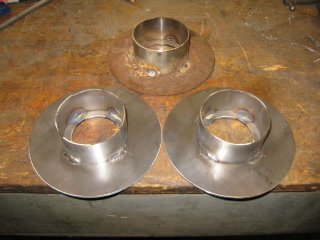
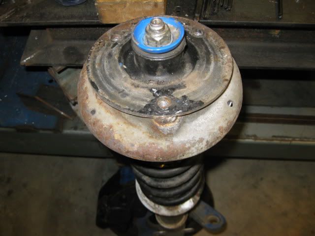
My blue 88 clone has been running 88 front springs in the rear since 2009 and a member asked me to make him a set up the upper spring hats. I did a poor job documenting them when I made the original set, so here are some build pics:
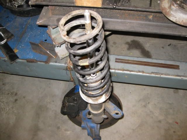
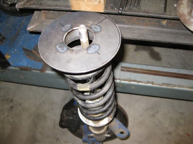
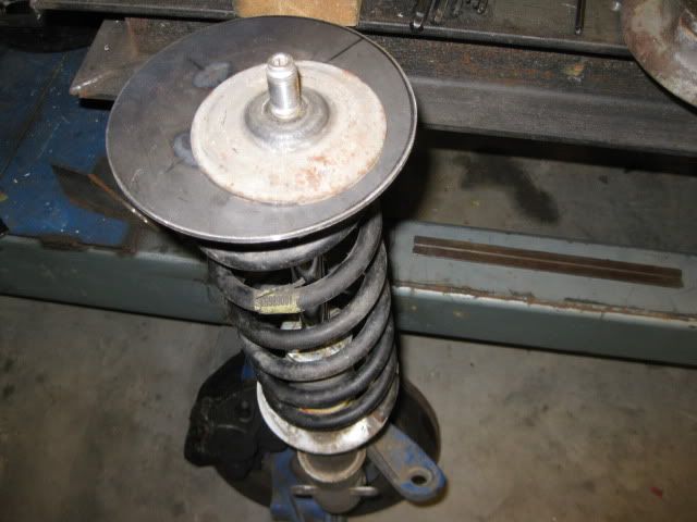
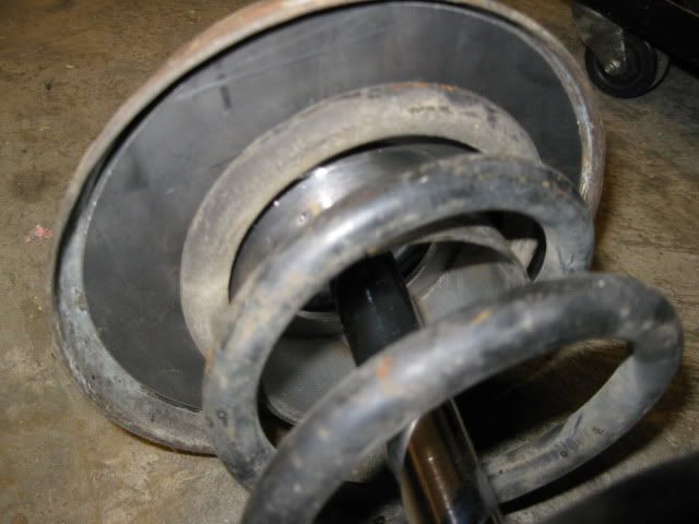
And the assembly process: Notice the black strut bushing has been flipped over to gain an additional 1" of travel in compression (for lowered cars) The original upper spring hat keeps the new one in position:
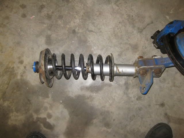
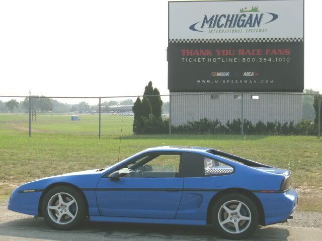
Now why would you want to do this... It is a cheap way to lower the 88's and get an approximate 35% increase in spring rate. Just use the 84-87 front springs up front (remove 1 1/2 to 2 1/4 coils... depending on how low you want it), then take your front 88 springs, cut 1 coil off and install them in the rear with this new upper spring hat. The end result is a stance very similar to this one (24.6" diameter tires):
[This message has been edited by fieroguru (edited 04-11-2011).]
Wouldn't it have been easier to weld smaller brackets to your rear cradle cross-member and suspend the muffler with springs like the OEM Fiero?
quote
Originally posted by fieroguru:
What is this "easier" word you are referring to... not sure I know what that means.
Blooz, You'd have to know Paul to fully understand but, I can assure you, whatever he does may not be the easy path but, it will hold together. Yeah, he's a bit nutty also.
Ha! (I refuse to use LOL). I've seen the weird things he does to perfectly serviceable water pumps, Blackrams... I know he's nutty.
By the way Guru, welcome to your new home in the Contruction Zone! This thread is certainly worth it (Of course that means that all the rest of us are going to have to work a little harder to stay on page 1 given the daily updates you keep pumping out).
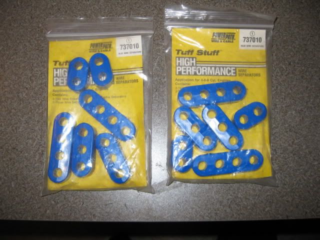
I ordered the 10mm plug wires, the coil terminals and the wire separators. So far the wire separators are the only parts that have come in:
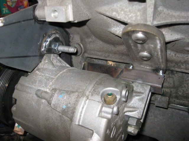
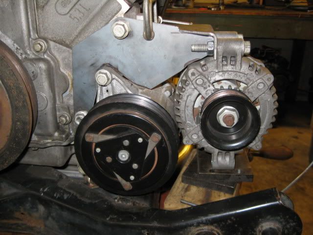
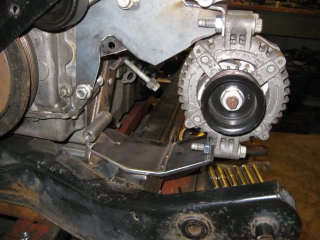
Been thinking about the AC and Alternator mounting for quite some time and think I have it figured out. First order of business was to mock up a relatively stiff upper support to hold the AC compressor in the right general location so I could finalize the bottom and backside mounting points. Also used my angle pulley alignment tool to ensure the AC compressor was at the proper depth:
I picked up some metric nuts, then tuned one down to fit inside a tube (a section of an 88 trailing link tube), welded it in place and then turned the weld down smooth. I had to mill a flat on the back side to clear the thicker portion of the front engine bracket. This tube will act as the lower AC compressor mount. It is just tack welded to the front engine bracket, but it will be fully welded:
For the rear mount, I am planning to weld a nut into a 1x1 square tube and then cut its legs to fit up against the thick portion of the front engine mount:
The front engine mount will also have a lower strap that will go under the AC compressor and support the bottom side of the LS4 alternator. Then I will go back and remake the upper bracket that goes above the AC compressor and it will connect to the top set of bolts on the Alternator.
[This message has been edited by fieroguru (edited 04-18-2011).]
The plug wires and coil terminals showed up last week, and I ordered the Spec Stage 4+ clutch on Wednesday...
The rear A/C support boss is tacked into place and that restores the AC compressor to 3 points of attachment just like stock:
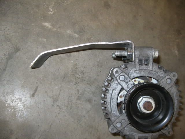
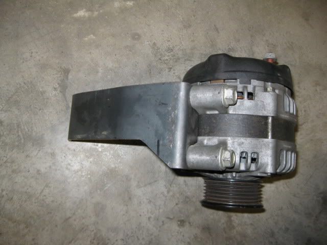
I decided to stick with the LS4 alternator and incorporate the top portion of the bracket with the 1/8" plate that supports the AC bracket. So I bent some more 1/8" material, bent it a couple of times to provide some stiffness and clear the engine block, then tack it to the upper AC bracket:
The nuts for mounting the Alternator will be welded to the back side of the bracket and a small gusset will be added to the belt side to close off the nut area. The bottom bracket will be similar and come from under the AC compressor to attach to the alternator.
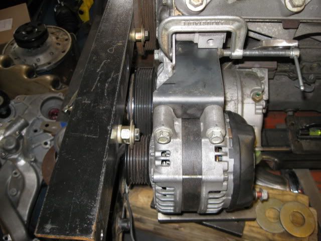
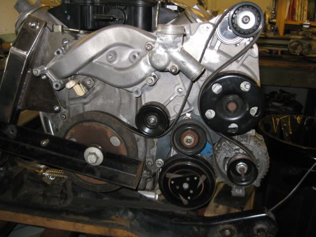
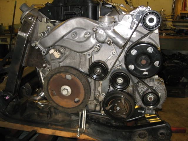
Since, the alternator could now hold itself into position, the water pump and the last idler (just held in place with a magnetic base) were installed to show the final belt routing. I will find a smaller diameter idler for the one between the Alternator and AC. The balancer, alternator and AC compressor all have quite a bit of wrap, so there should not be any issue with belt slippage.
[This message has been edited by fieroguru (edited 04-23-2011).]
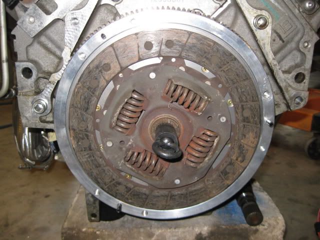
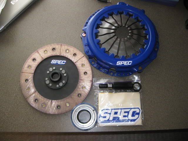
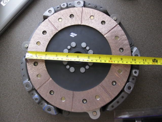
The clutch arrived today! The list price was $639, but I was able to get it for $575 shipped through LMPerformance.com. This is the 2nd most expensive part for this swap ($749 for the Camshaft kit was #1) excluding the original purchase price the engine...
The clutch disk measures at 9 13/16" at the friction material (listed as a 10" clutch) and is one of the largest diameter clutches you can get for this application w/o mixing/matching disks and pressure plates or getting into some trick self adjusting pressure plates.
It weighs in at 16.52 lbs on the wife's 30 lb postal scales, so the combined flywheel/clutch/pressure plate will be 27.7lbs... which is about 15 lbs lighter (and the flywheel about 1" smaller diameter) than my old SBC flywheel/clutch/pressure plate setup or about 35% lighter... that should help free up some more whp!
The other bit of good news is I might have my 4T65E-HD sold for $650 and that should offset the hit to the wallet from the clutch.
[This message has been edited by fieroguru (edited 04-26-2011).]
More progress on the Alternator bracket. I still need to weld this lower plate into the front engine mount/AC bracket and notch the cradle directly under the bracket to allow 1/4" movement, but it is starting to take shape:
I found the sister to the more rounded pulley off the balancer and used it for the AC/Alternator idler. Then figured out where it needed to be for clearance all around and drilled the upper plate for the idler. Then a scrap belt was clamped together to show the final accessory drive. I will cut the belt at the clamp, measure the length and pickup a new belt:
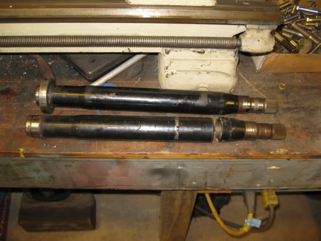
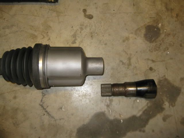
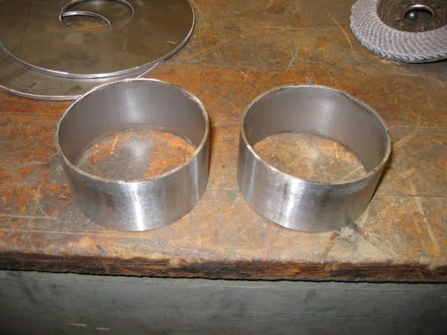
Also, started messing around with intermediate shafts. Originally, I had planned to just use the custom tripods I made for the SBC/F40 swap, but the Passenger side tripod will not clear the side of the block (Y-block construction strikes again and the F40's axle location is closer to the block). So I will probably use the modified tripod/corsica axle on the driver side (short axle) and then use a stock G6/F40 Driver side axle on the passenger side with a longer custom intermediate shaft. I had picked up a couple of Saab 9-3 intermediate shafts and will cut them apart, machine a hollow sleeve to go inside, press them back together and weld them together at the seam and 4 plug welds on both sides of the main seam. The wall thickness of the intermediate shafts is about 4mm and the I.D is about 1.45"... so I will turn down some 1.5" tubing to make the inner sleeve. Here are the two shafts with one already cut apart:
[This message has been edited by fieroguru (edited 04-26-2011).]
Since you helped me with some info, I'd like to repay the favor. I found a place to send the F40's in for cryo and WPC treating. If you want, they'll also order and install a Quaife LSD for you. The owner Dave says it will make the tranny easily hold 450 lb tq. He's done a bunch of them for Archie over the past couple of years. Anyway, if you're interested then you can find their contact info in my thread here... Not trying to hijack your thread, keep up the good work!
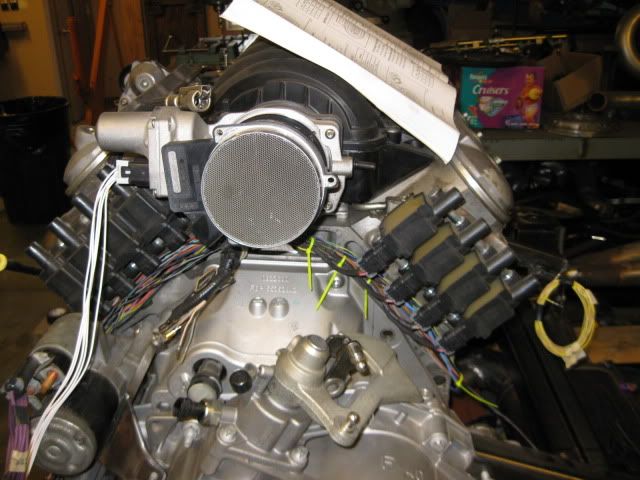
114" belt to 80" belt 5 idlers, reduced to 3 Alternator up top at rear of engine to down low at front PS pump from up top to in trash can (actually just sitting on the shelf) Lots of stuff visible on top, to just the new tension idler
[This message has been edited by fieroguru (edited 04-27-2011).]
Since you helped me with some info, I'd like to repay the favor. I found a place to send the F40's in for cryo and WPC treating. If you want, they'll also order and install a Quaife LSD for you. The owner Dave says it will make the tranny easily hold 450 lb tq. He's done a bunch of them for Archie over the past couple of years. Anyway, if you're interested then you can find their contact info in my thread here... Not trying to hijack your thread, keep up the good work!
Honestly, I think installing an LSD will probably do more harm than good, if one intends to drive the car excessively hard (fast shifting, landing back near peak tq). And especially if one has good, sticky tires on good suspension. It is much more likely for stuff to break in that condition, since the LSD actually prevents slip from happening, where it would be useful.
Since you helped me with some info, I'd like to repay the favor. I found a place to send the F40's in for cryo and WPC treating. If you want, they'll also order and install a Quaife LSD for you. The owner Dave says it will make the tranny easily hold 450 lb tq. He's done a bunch of them for Archie over the past couple of years. Anyway, if you're interested then you can find their contact info in my thread here... Not trying to hijack your thread, keep up the good work!
Thanks for the info, and am sure a few will find it useful.
Cryo treating transmissions has been around for quite some time and has been done to getrags and isuzu's with favorable results, but I am not convinced the F40 needs any additional upgrading. I fully expect to shear off the stock fiero outer CV at the wheel bearing hub before the F40 will give up the ghost, so it doesn't really make since to throw more $$ at the transmission unless I am going to do the same for the axles... and the axles really would need to come first. If/when I frag my first F40, I will look at doing something different, but until then dropping any additional $$$ into an essentially disposable transmission w/o any real proof of them being failure prone to begin with just isn't in my budget nor in the scope of my engine swap.
Originally posted by fieroguru: I fully expect to shear off the stock fiero outer CV at the wheel bearing hub before the F40 will give up the ghost, so it doesn't really make since to throw more $$ at the transmission unless I am going to do the same for the axles... and the axles really would need to come first.
Speaking of axles, have you figured out what solution you're going with there yet? Also, going with a half-shaft should help a bit too, since the axles should be much closer in length at that point.
Originally posted by dobey: Speaking of axles, have you figured out what solution you're going with there yet? Also, going with a half-shaft should help a bit too, since the axles should be much closer in length at that point.
My problem is I think about stuff too much...
Longterm, I want to stuff some wide wheels in the back and want to upgrade the bearings/CV's and would prefer to run a 4 3/4" pattern (cheap/wide wheels). In looking at the stock 88 rear upright, I noticed that the bolt pattern for the bearing is not centered in the raised portions of the casting, they are slightly inset. I have some S10 4x4 front wheel bearings and while they will not fit in the center bore of the upright, their flange pattern is very close to being centered in the raised portion of the casting. So it might be possible to bore the upright to accept the larger wheel bearing, but before reaching the final size, weld the existing bearing bolt hole shut, finish boring the upright and then redrill the 3 mounting holes. I belive the uprights are ductial iron so welding the holes closed shouldn't be much of an issue.
Another approach to use the S10 wheel bearing... the center bore is very close to accepting the first step in the S10 wheel bearing. So I could make it fit this first step, then make a spacer ring (about 1/2") to suppport the bearing and change the bearing pattern. Doing this moves the wheels outboard, but I could just shorten the lateral links and pull them back in.
While researching this I have also been thinking about the G6 F40 axles... I have a set on the shelf and they come with a 30 spline at the wheel bearing. They already are a larger diameter (potentially stronger) than the stock fiero size stuff so I looked to see what wheel bearings came with 4 3/4" and 30 spline = C5 rear wheel bearings... I haven't confirmed that the diameter of the 30 splines are the same, but I do know the C5 stuff would come with ABS sensors and cost quite a bit more than the S10 ones currently setting on the shelf.
The largest diameter for the CV/bearing spline is from the later model 33 spline (3800 SC, N*, and most mid to full size FWD applications). I have a couple of these outboard CV's on the shelf as well and they would probably result in the strongest CV assembly. But the bearings that accept the larger 33 spline CV's do not come in the 4 3/4" pattern, but in the 115mm and others... and I am not sure I want to deviate away from the 4 3/4" pattern.
Right now, I am anxious to get this thing running, so I will most likely table the bearing/CV upgrade and just use the modified corsica tripod/axle for the DS (same one I built for my SBC/F40 swap) and take my two Saab intermediate shafts and make a longer one the needed length to allow a stock length G6/F40 axle to work (just need to swap out the CV end with a fiero one). Or I could use one of the Saab axles on the shelf as well since they have the fiero size outboard spline... this would save me from needing to swap the ends (a true factory axle assembly) and they are far more common and cheaper than the G6/F40 parts. Either option would allow my setup to run stock axle shafts and make replacement easier in the event I break one. If I happen to break the custom tripod housing or the custom length intermediate shaft... then I will probably go with a custom set of axles at that point using the largest components I can find.
I ordered the material to make the inner sleeve for the intermetiate shaft last night, so hopefully I will get started on it soon.
[This message has been edited by fieroguru (edited 04-28-2011).]
Haha. I know what you mean. I am trying very hard to keep myself from buying another car for a project right now. Don't need any more right now. The 2 I have is enough.
I was also wanting to use wider wheels/tires on mine, and the 4.75" bolt pattern, but I think I just want to get it running and in the car right now, and then go from there. Getting into changing all the suspension is just going to make it take much longer to get done.
I definitely am looking forward to see what your ideas for using the stock G6 axles with the extended half shaft come out like. You're doing a great job on everything so far. Awesome as always!
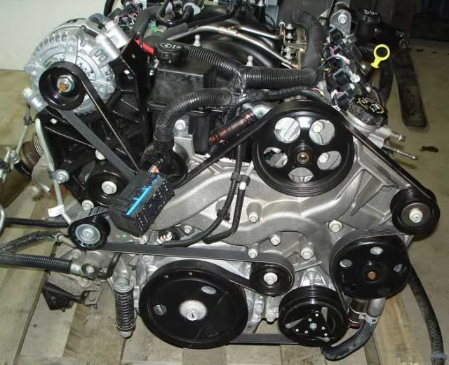
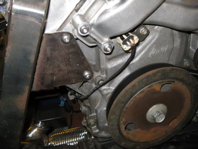
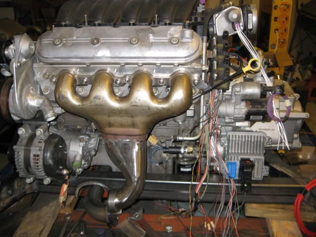
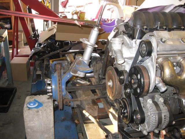
The accessory drive is finished. Completed all the final welding for all the brackets, idler pulley standoff and the slight notch in the front crossmember:
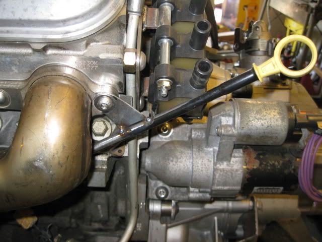
Then I made a small bracket so the dipstick tube will attach to the front manifold:
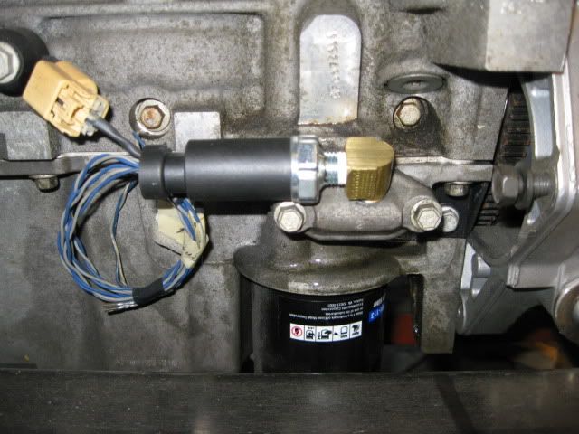
Drilled and tapped the oil bypass cover for the oil pressure sending unit for the gauge:
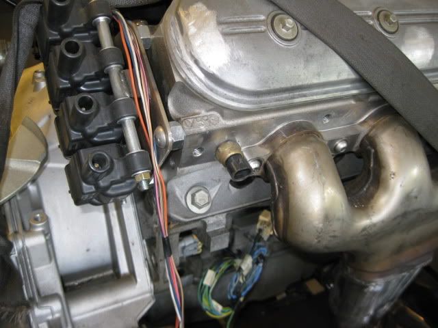
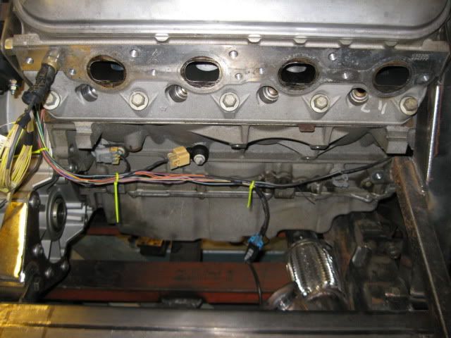
Relocated the temp sensor to the rear bank by cyl 8. This is the hottest cylinder and tends to be the first cylinder to detonate and kill the engine if excessively abused. Adding the 4 corner vent tubes will help eliminate hot spots, but I would rather have the ECM start pulling some timing in the event that cylinder 8 starts to get hot.
I am planning to drill/tap the coolant sensor hole by cyl #1 for the temp sender for the gauge. Still need to order a new fiero temp sensor.
Ran the welder out of Ar/CO2... so can't do any welding for the rest of the weekend. This should allow me to focus on the harness and other odds/ends for a couple of days.
Originally posted by fieroguru: Relocated the temp sensor to the rear bank by cyl 8. This is the hottest cylinder and tends to be the first cylinder to detonate and kill the engine if excessively abused. Adding the 4 corner vent tubes will help eliminate hot spots, but I would rather have the ECM start pulling some timing in the event that cylinder 8 starts to get hot.
I am planning to drill/tap the coolant sensor hole by cyl #1 for the temp sender for the gauge. Still need to order a new fiero temp sensor.
Isn't #8 on the other side, and #1 the one nearest the passenger side strut tower? I think you need to move that sensor to the other side if you want the #8 cylinder.
Isn't #8 on the other side, and #1 the one nearest the passenger side strut tower? I think you need to move that sensor to the other side if you want the #8 cylinder.
Nope. For GM V configuration applications, #1 is the cylinder closest to the balancer with 1 bank always being slightly ahead of the other. For V8's the DS (or front bank in fiero speak) has cylinder #1 and the passenger or rear bank has cylinder #8. Where this gets confusing is on the 60 degree V6 the PS bank is further forward, giving it cylinder #1.
For the temp sensor you can get a 3 wires sensor that will work for both the ECM and the Temp gague in the dash, I am running this sensor in a truck i put a ls in.
quote
Originally posted by fieroguru: I am planning to drill/tap the coolant sensor hole by cyl #1 for the temp sender for the gauge. Still need to order a new fiero temp sensor.
[This message has been edited by blander66 (edited 05-01-2011).]
For the temp sensor you can get a 3 wires sensor that will work for both the ECM and the Temp gague in the dash, I am running this sensor in a truck i put a ls in.
Do you have a part # or application for the sender?
For the temp sensor you can get a 3 wires sensor that will work for both the ECM and the Temp gague in the dash, I am running this sensor in a truck i put a ls in.
Found it:
3 wire LS1 temp sender GM # 12551708, application 1998 Camaro w/ LS1, pigtail is the same as the TPS sensor on the fiero 2.5 and later model applications.
The bottom wire is for the gauge.
Only downside to using this 3 wire setup is I will loose the temp light, but the gauge is much more important anyways. I like the idea of 1 less sensor.
[This message has been edited by fieroguru (edited 05-01-2011).]
Originally posted by fieroguru: Nope. For GM V configuration applications, #1 is the cylinder closest to the balancer with 1 bank always being slightly ahead of the other. For V8's the DS (or front bank in fiero speak) has cylinder #1 and the passenger or rear bank has cylinder #8. Where this gets confusing is on the 60 degree V6 the PS bank is further forward, giving it cylinder #1.
Ah, right. Guess I've been spending too much time with the V6s.
Probably my least favorite part of any swap... wiring.
Started with the cam sensor, wrapping around the rear of the engine picking up the O2 sensor, oil level sensor, bank 2 knock, crank position sensor, VSS and coolant temp sensor (still needs to be added). Then up over the bellhousing where I have the first 4 coils added to the harness (ignore the yellow wire ties... they are just temporary).
Still a lot more wires to add... (wide band o2, 4 more coils, 8 injectors, DOD connector, oil pressure sender, reverse lights, DWB throttle body, MAF, MAP sensor and starter. Then I will start with the Alternator, AC, bank 1 knock, oil pressure sender (gauge) and combine with the main harness. The car does not have a 500 connector on the passenger strut tower, so there is no need for any wires to cross over the accessory belt.
The ECM is shown in the approximate location it will be mounted (let the flood gates open to tell me how stupid it is to put it there!). I want the drivetrain to be almost entirely self-contained with the bare minimum of connections to the chassis, so the ECM needs to be mounted on the cradle somewhere away from excessive heat and I really do not want to see it (or the wires going to it).
[This message has been edited by fieroguru (edited 05-01-2011).]
Sold the 4T65e-HD this afternoon for $575... not bad considering I purchased the engine/transmission combo for $1000. Now I need to decide on which wide band to get...
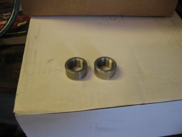
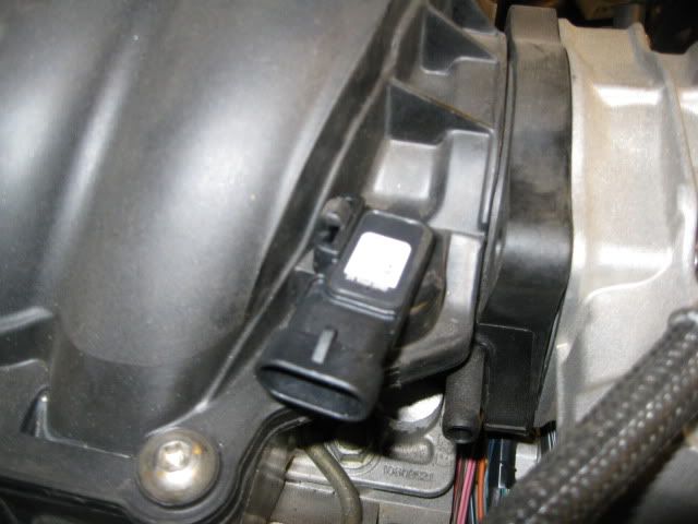
The stainless o2 bungs came in today, as well as the LS2 map sensor (LS4 one will not fit the LS2 intake):
Purchased an Innovate LC-1 wide band with gauge, MAF pigtail, and 3 wire temp sender... waiting on them to come in.
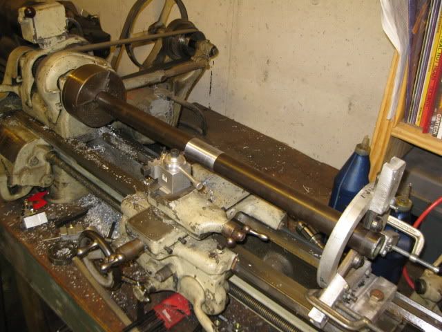
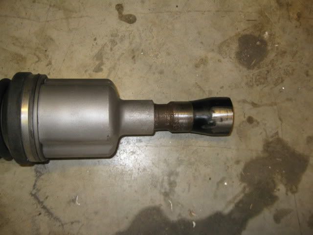
So I went ahead and turned down the shaft that will slide inside the Saab intermediate shafts to lengthen them. About 12" length was turned down to the proper size:
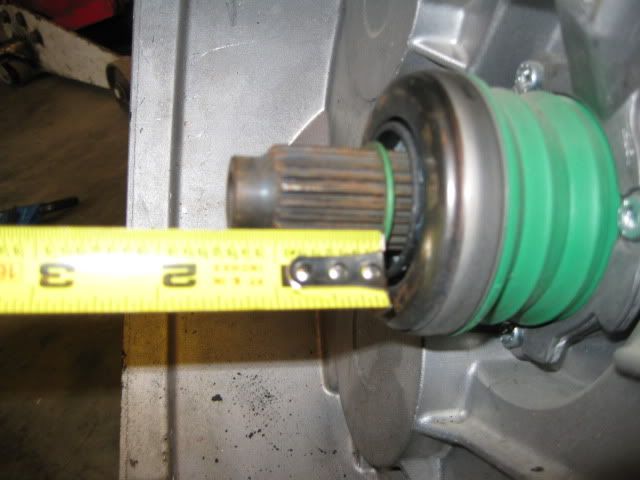
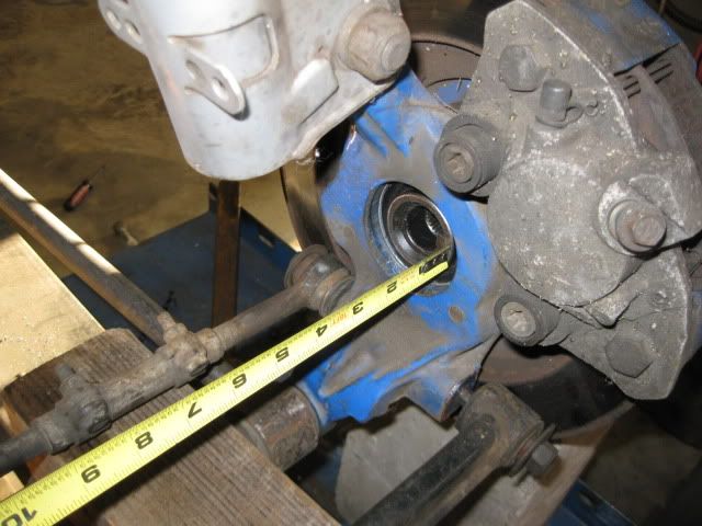
Then mocked up the passenger side suspension to figure out how much longer the intermediate shaft needed to be.
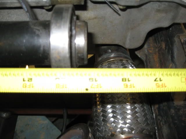
With the lateral links approximately level (they will actually be pointed up due to its lowered stance) and a saab intermediate shaft in the transmission, the distance from the back of the wheel bearing (where the outer CV seats) to the end of the intermediate shaft was measured = 19 1/4":
With that I went and measured the fully compressed and fully extended length (from base of bearing on CV to edge of seal surface on tripod - not the overall compressed length as shown in most catalogs) of the G6 F40 Driver side axle: fully compressed 16 7/8", fully extended (edge of rollers at edge of tripod cage) = 18 1/4", midpoint = 17 9/16
So to center the tripod at stock ride height with the G6 F40 driver side axle the intermediate shaft needs to be 1 11/16" longer.
I will probably start with the intermediate shaft extended 1 7/8" and tack the two tubes together w/o the inner sleeve and then do test fit and cycle the suspension to check for binding. If I need to make it shorter, that would be easy at that point, making it longer... not so much, so I will start with it slightly longer to begin with.
Changing gears... now if you are going to be chopping up 2 saab intermediate shafts, you could assemble two male ends vs keeping the current 1 male and 1 female setup. The only issue doing this, is the male end of the intermediate shaft is shorter than a normal tripod spline section and is missing the snap ring that retains it within the transmission (it didn't need one with the intermediate shaft support bearing ensuring the intermetiate shaft stays properly seated in the differential).
A resourceful person could install a bolt on extension to the male end of the intermediate shaft to accommodate a retaining ring (doesn't seem much force) and make this male/male intermediate shaft setup work.


 Now get to work!


 (Of course that means that all the rest of us are going to have to work a little harder to stay on page 1 given the daily updates you keep pumping out).