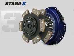
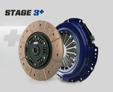
I have put a combined 45K miles on my SBC/Getrag setup with a Spec Stage 2+, Stage 3 and Stage 3+ so. These were 9 1/8" and while the Stage 2+ had the absolute best street manners, it wouldn't hold. I chose that clutch after trying the Stage 3 (sprung 6 puck). It would hold the power, but sucked with driving it daily in stop/go traffic. The stage 3+ had street manners much closer to the stage 2+ and would hold the power. Here are some generic pictures to show the difference between the Spec Stage 3 and the Spec Stage 3+
The Stage 3 was developed to improve the street manners of the Stage 3 series while still having excellent holding power.
The Clutch I am going with is a Stage 4+. The only difference between the stage 3+ and Stage 4+ is the solid hub vs. the spring hub. My old SBC setup was solid mounted and the LS4/F40 setup will be rubber isolated, so that should help smooth out the engagement. Also the 9 7/8" diameter vs the 9 1/8" should also help smooth the engagement as well... only one way to know for sure.
For the guys looking for a less aggressive clutch, Spec offers this clutch in all their various stages (which are much cheaper). AC Delco also offers a kevlar disk version as well, and Autozone sells a stock and heavier duty one (higher clamp load pressure plate).
The downside of this clutch is it will require a custom flywheel... but that is part of the F40 challenge in general.
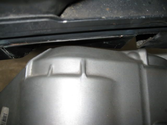
The relocated frame notch is going to workout just fine:
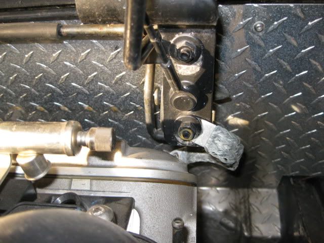
Here is the clearance to the decklid hinge box... but the water pump isn't on the engine.
Both hinge boxes are being removed. I got the idea from Jefrysuko at the 25th and hope to have that modification done in the next week. So with them going away, my aluminum firewall panel will also need to be removed and replaced:
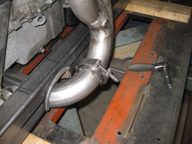
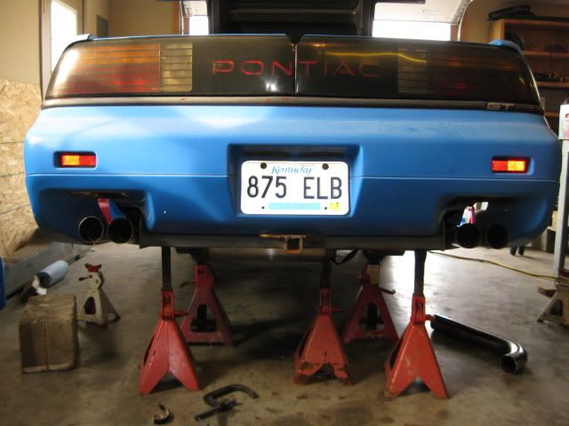
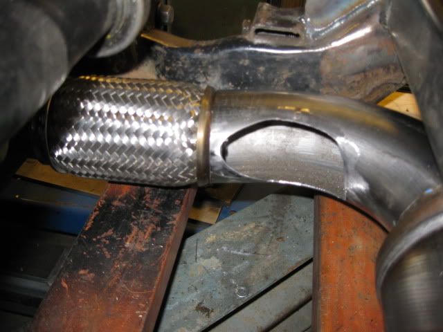
Here is a very rough mockup of the exhaust as it would exit the rear.
Wednesday this week the wife and girls are going to Chicago to visit family for 10 days! The lack of daddy duties and noise/fume curfews for 10 days should really help speed things up a great deal!
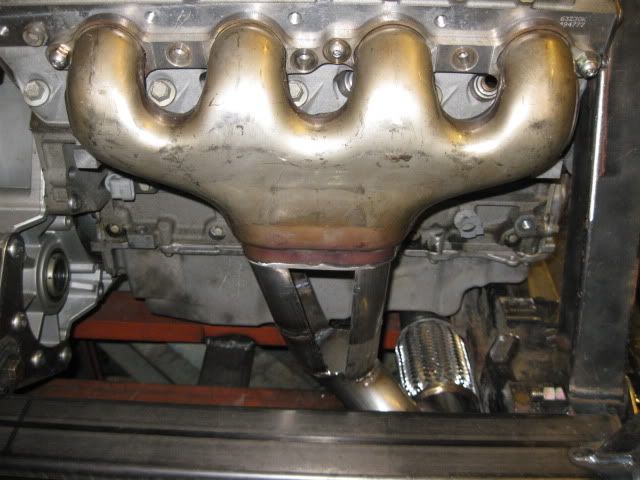
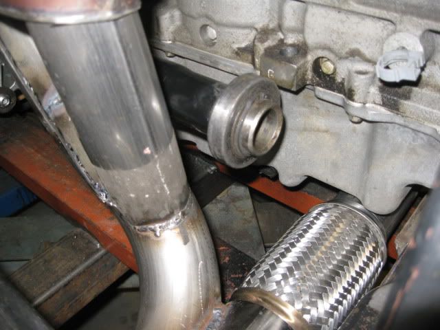
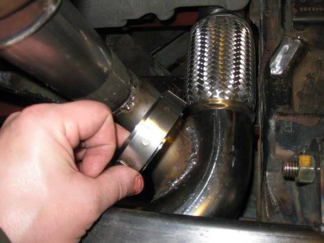
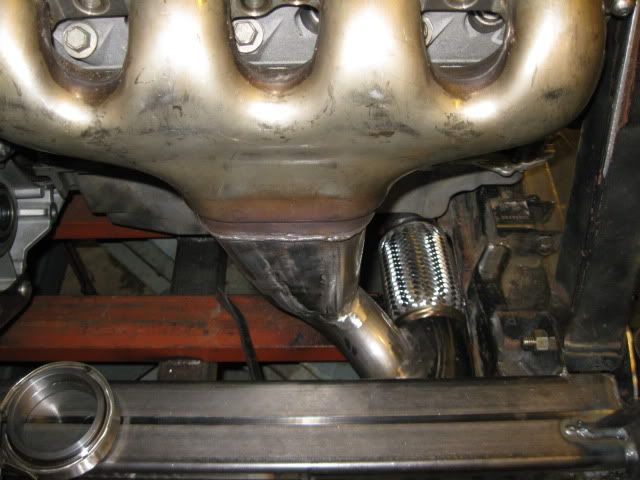
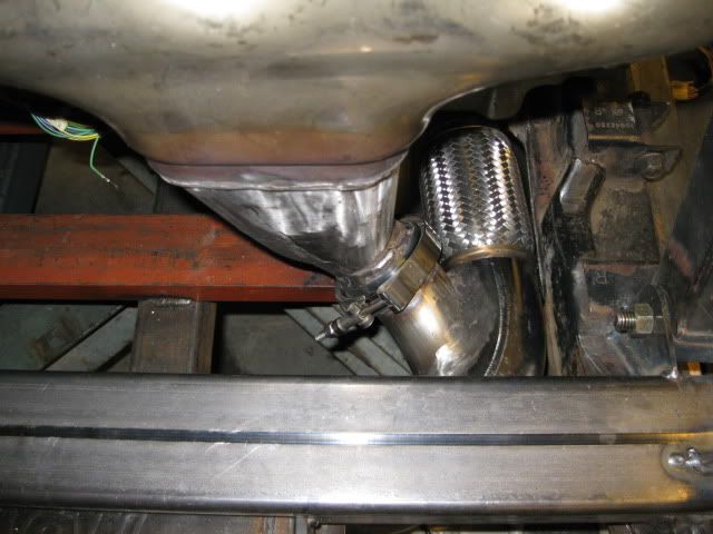
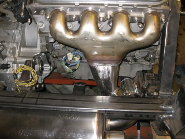
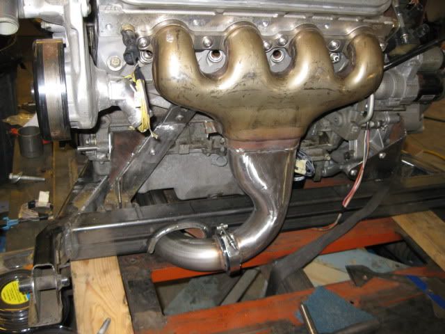
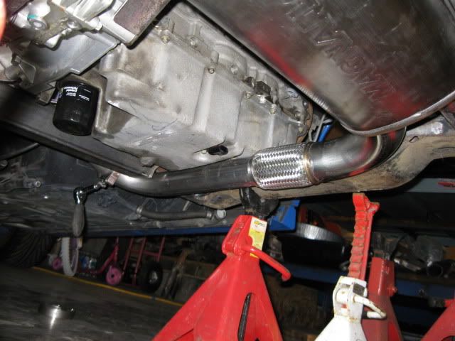
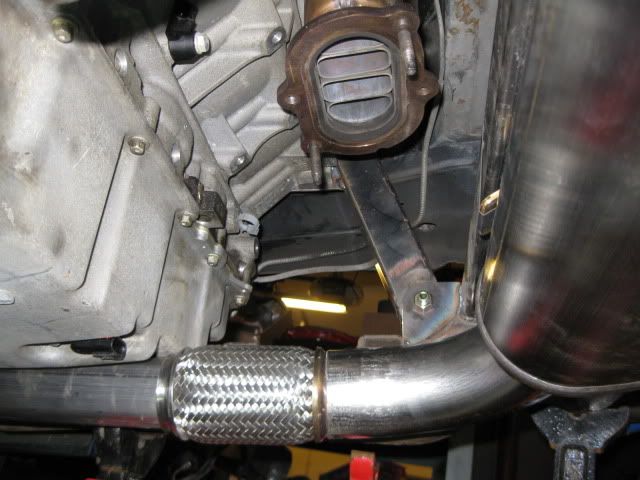
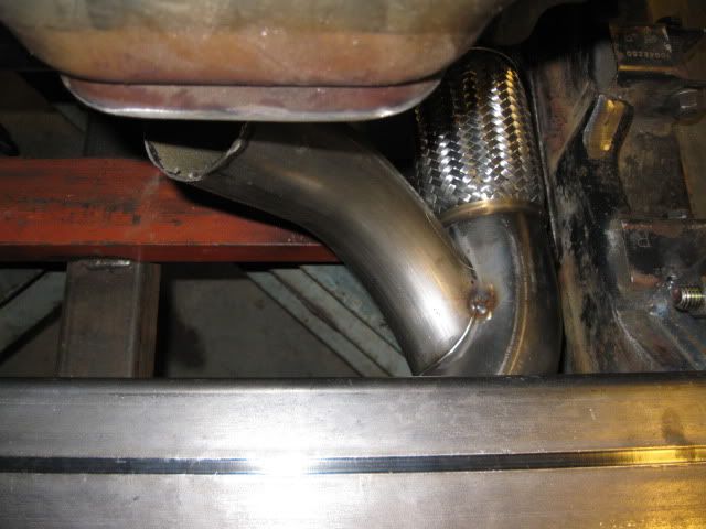
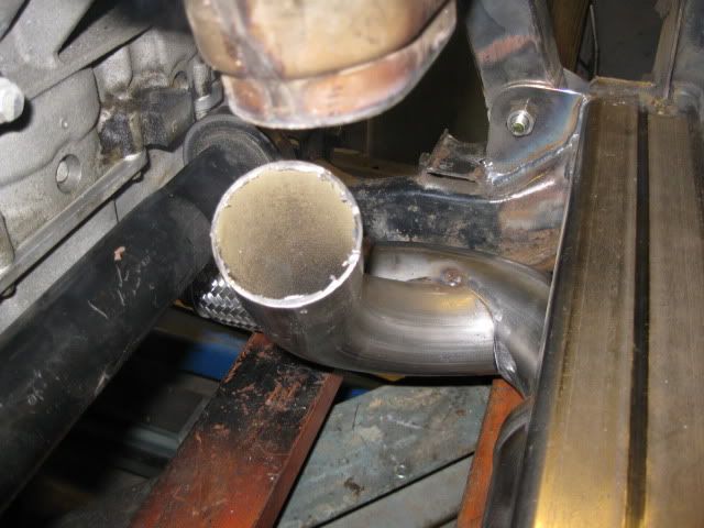
Here are a couple more progress pics to show how the exhaust will be routing:
It is 2 1/2" coming from under the oil pan, into a flex coupler then to 3" mandrel bend into the muffler. The rear bank will come down and merge into the 3" section prior to the muffler... that one will take some time.
It will be a Spec Stage 4+ (solid hub and solid ring of friction material) of the version I just test fitted. The list price is over $600, but it includes a HTOB that I will not need, so maybe I can get the cost down some.
Yes the clutch is alittle overkill at the moment, but wanted to make sure it would hold any future upgrades (NOS, Turbo, stroker kit, or a 6.0, 6.2).
Hey Guru,
First, great work!!!
Second, I have the spec 4+ with the springless hub and solid disc material. It is a very streetable clutch, it does like a little rev (maybe 1700) but will engage very smooth with that. G/L Ray
unreal motor build! there is easier ways of getting 400 hp though hahaha. but seems like you got a good head on your shoulders and know what you are doing. very nice build! i cant wait to hear it and see it run on youtube or in person.
this is a great thread and a top notch build . in the futuer do you see your self having the block sleved to a bigger bore i know Darton can bring it out to 4.250
this is a great thread and a top notch build . in the futuer do you see your self having the block sleved to a bigger bore i know Darton can bring it out to 4.250
I probably will not mess with resleeving the block. If decide to increase cubes, I might stroke it or just get a 6.0 or 6.2 short block. The LS4 block is actually longer than the LS4, so there is room to put a 3/16 to 1/4" adapter plate on the RWD block without increasing the overall width of the engine/transmission. You still need to shorten the crank 3mm at the flywheel and 10mm on the font, but I could drop a RWD block in with minimal rework of the existing setup.
Fuel efficiency at interstate speeds is a primary goal for this swap, so there is a better chance I would add a turbo (in the rear where the muffler is) vs. adding cubes...
Originally posted by fieroguru: I probably will not mess with resleeving the block. If decide to increase cubes, I might stroke it or just get a 6.0 or 6.2 short block. The LS4 block is actually longer than the LS4, so there is room to put a 3/16 to 1/4" adapter plate on the RWD block without increasing the overall width of the engine/transmission. You still need to shorten the crank 3mm at the flywheel and 10mm on the font, but I could drop a RWD block in with minimal rework of the existing setup.
Fuel efficiency at interstate speeds is a primary goal for this swap, so there is a better chance I would add a turbo (in the rear where the muffler is) vs. adding cubes...
If you do increase the cubes with an LS2/3 block, you could just swap in the LS4 crank instead of machining the RWD crank. All the LSx cranks are the same stroke, save the 4.8 and 7.0 engines which are slightly shorter or longer, respectively. If you want to stroke it, then machining the ends on an LS7 crank is probably the best bet, unless you want to spend the $$$ and go for a forged crank.
Originally posted by dobey: Not a whole lot of room there. What are you planning for a heat shield? does it clear with the stock heat shield?
I am thinking about taking some of the left over 3" exhaust pipe and weld a heat shield to that corner of the muffler leaving about 1/8" between the tubing and the muffler.
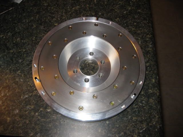
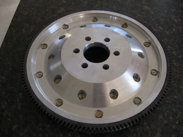
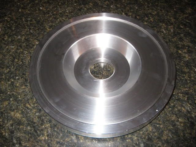
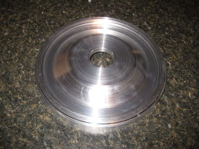
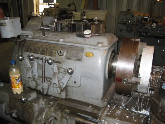
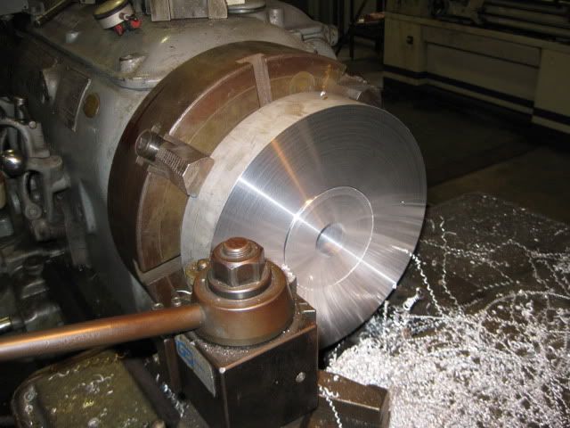
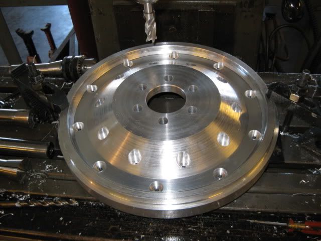
After about 4 hrs on the road and 6 hrs running a large lathe... phase 1 of the flywheel fabrication is complete:
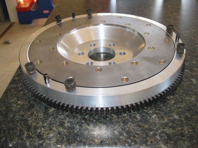
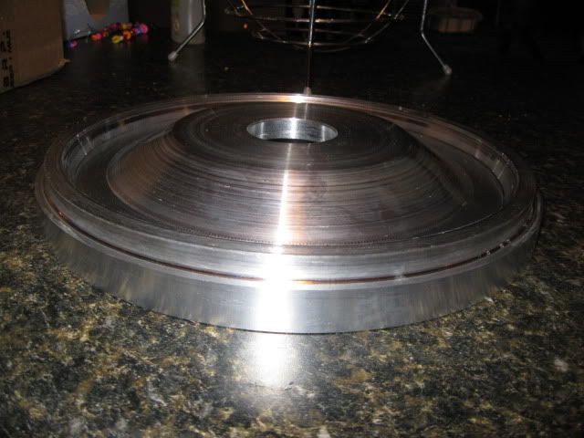
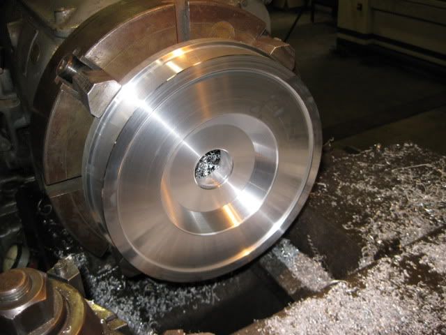
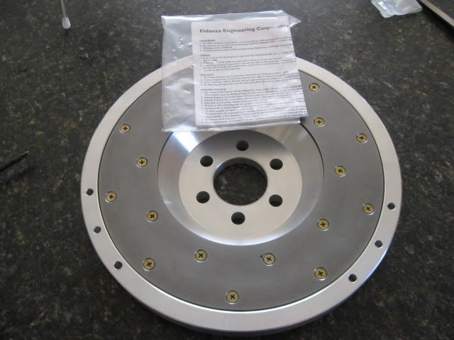
With the wear strip just sitting in place:
My new favorite tool. When I decide to buy a house again and get back to a 3000sq-ft garage, I am going to get me one of these bad boys. It was a lot more fun using it vs. my dinky southbend lathe.
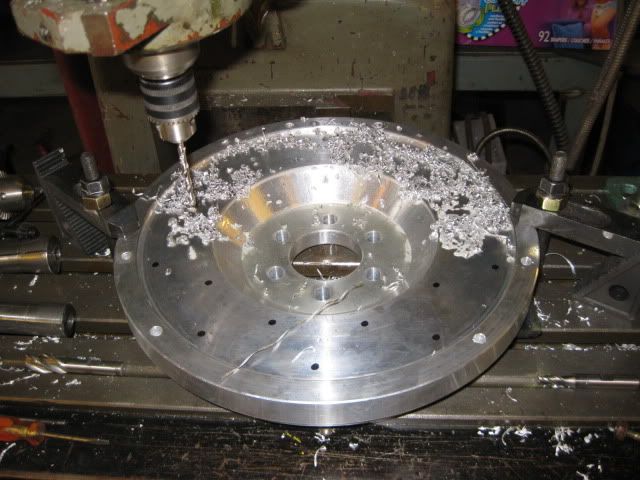
On Sunday I will get the flywheel setup in the mill and drill the crank, pressure plate and friction plate patterns.
Nice! Is the distance from the block to the ring gear going the same on your new custom flywheel, as with the stock LS4 flexplate?
I was looking at a 10" benchtop lathe today at Harbor Freight myself, as a means to machine a custom shifter and maybe some other small things.But it was like $500 so I'll pas for now. Should get a small hydraulic scissor lift first, to make working on my cars much easier.
Me likey. This by far seems to be the best design for the F40. Certainly a better design than the flex plate/spacer/flywheel idea. The countersunk hub is going to make finding suitable flywheel bolts easy too, heck, you could use bolts with full thickness heads. Great pics!
Edit: What's it weigh with the wear lining?
[This message has been edited by Bloozberry (edited 03-26-2011).]
I've said it before and I'll say it again - Amazing work! Your threads and Blooz's thread keep me inspired! Thanks again for sharing all your great work.
Now, on a side note, I just finished a "rehab" of my SBC Coupe. Rebuilt 350 - 030 over - nothing crazy - just a nice clean running engine. It is a 70 4-bolt main motor out of a Monte - rated @ 300 HP in it's stock form - I'm hoping for 330 plus? It's bolted to a 4 spd. After taking it for a few "spins" over the last couple days, I think I am going to have clutch issues - it's a Ram clutch. I'm just wondering what you would suggest for an upgrade. Sounds like the 3+ may be the way to go? It's not a daily driver - mostly a play toy that will go through a few transitions over the next year. Future plans are for some aftermarket injection setups, updated heads, etc. I want to build it in steps just to see which does what and what the gains/losses are for each. I guess it's a "test" bed for fun! Thanks in advance.
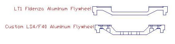
This flywheel was designed specifically around the LS4/F40 combination, so I kept the placement of the LS4 ring gear from the flex plate the same. I used the aluminum LT1 Fidanza flywheel as a guide for contour, material thickness and material type and tried to replicate it as much as possible. I also used used a fidanza friction plate (#221021 6" ID x 10 1/4" OD, #221091 is 6" x 10" and would work better with smaller ID clutches).
The 12 x 2 1/8" aluminum tipped the scales around 27 lbs, but after the first round of machining was down to 8 lbs. The friction plate, its bolts and the ring gear will bring the weight back up some, but it will probably be around 12 lbs. The ring gear weighs 2 lbs, but I have not weighed the friction plate/bolts... and I need to remove quite a bit more aluminum for the counter sunk friction plate bolts. In stock form, my clutch combo is supposed to be 18 lbs vs. the 16lbs of the stock fiero 2.8 setup
I should have taken this route at the very beginning...
For a Fiero SBC/Getrag combo, I found that the Stage 3+ was the best well rounded clutch for holding power and drivability. While I have never had a single Spec clutch failure, there have been many examples of failures due to the spring popping out of the hubs. So if you want to eliminate that issue, the stage 4+ is the same clutch as a stage 3+, just with a solid hub vs. sprung hub.
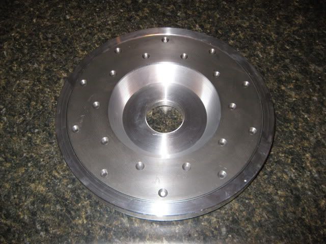
All that is left to do on the flywheel is to tap the 6 pressure plate holes and purchase/install the ring gear. After the flywheel had its center dial indicated, all the holes were drilled via X-Y coordinates from the print. For the wear strip I put it in place and used a sharpie to mark the general locations of the holes to help validate proper hole placement. When drilling 29 holes and each hole has and X and Y coordinate to the X.XXXX values... it is easy to transpose or misread the values.
[This message has been edited by fieroguru (edited 03-28-2011).]
Here is a pic after I installed the alignment pins:
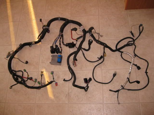
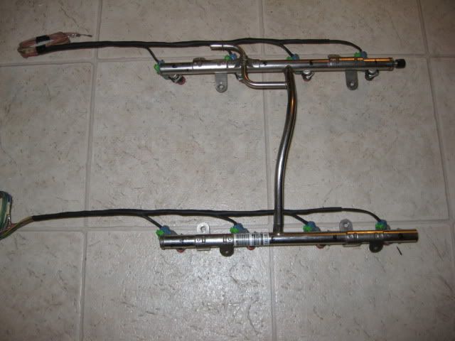
Ordered the ring gear, but can't do much else flywheel related until it shows up, so decided to be a little destructive while watching some TV: Stock LS4 harness:
After a couple of shows:
I will not be needing the TCM or the transmission connector, so I didn't take the time to take them apart... just cut them.
[This message has been edited by fieroguru (edited 03-29-2011).]
Got the fuel injector portion of the harness done. I will wire tie it up close to the fuel rail when it is installed to keep it tucked mostly out of sight.
Awesome work. I'm envious of your machinist skills. I do have a question on your exhaust system. From your pics it seems that the rear exhaust manifold will be solidly fastened to the remainder of the exhaust system with only the front exhaust manifold and it's downpipe isolated from the remainder of the system with a flex joint. Are you planning on another flexjoint immediately after the merge? If not are you concerned about any vibration/buzzing and/or any stress cracking over time?
Good luck with your build and may your project go as smoothly as your work is elegant
The rear manifold will be solid to the muffler back section. There will be two supporting arms that will come off the rear engine/transmission mounts to support the tail end of the exhaust and allow the exhaust to move with the engine/transmission vs. being mounted to the stationary cradle.
Ok. I'm wondering then why you used the flex for the front manifold/downpipe. If the whole exhaust system is going to float with the engine is the flex even necessary?
I'm a little confused on the issue of the flex section too. If you'r running the exhaust to move with the engine flex, are you concerned about what the tail pipe tips will be doing when you rug it? A half inch movement at the engine may translate to an inch or three at the tips.
[This message has been edited by 1fatcat (edited 03-30-2011).]
I'm a little confused on the issue of the flex section too. If you'r running the exhaust to move with the engine flex, are you concerned about what the tail pipe tips will be doing when you rug it? A half inch movement at the engine may translate to an inch or three at the tips.
Without the ring gear the flywheel is just under 10 lbs. So once the ring gear is added, it should be between 11 and 12 lbs.
While the engine is rubber isolated, the mounts are quite stiff (front A-arm suspension bushings from a mid 70's camaro) and spaced quite a bit apart, so I am not expecting much defelction, maybe +/- 1" of movement at the tips. Under acceleration the tips will lower and while engine braking the tips will raise. There will be atleast 2" of clearance between the tips and the fascia.
Ok. I'm wondering then why you used the flex for the front manifold/downpipe. If the whole exhaust system is going to float with the engine is the flex even necessary?
To keep the manifolds from cracking. If the front & rear manifolds are connected w/o a flexible joint, as the exhaust heats up and expands it will push the manifolds away from each other. This puts quite a bit of stress on the primary's and the manifold flange and leads to cracking (learned this from my SBC swap).
Originally posted by fieroguru: To keep the manifolds from cracking. If the front & rear manifolds are connected w/o a flexible joint, as the exhaust heats up and expands it will push the manifolds away from each other. This puts quite a bit of stress on the primary's and the manifold flange and leads to cracking (learned this from my SBC swap).
I wonder if that's a problem with the hydroformed LS7 manifolds though. No harm in being cautious of course, but the LS7 manifolds do seem a bit beefier.
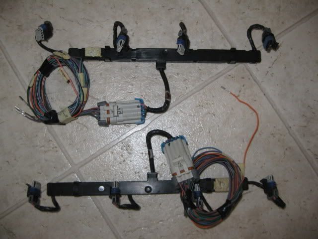
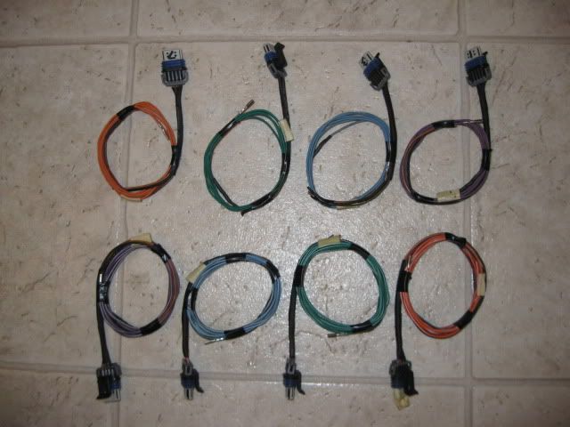
Spent some more time on the harness simplification. Since the coils were relocated, I had little use for the unsightly coil sub-harnesses, so I took them apart and wired up each coil individually. The first 4" or so from the connector was wrapped in heat shrink insulation to protect the wires and make the harness as small as possible when the individual coil wires come off the main harness along the bellhousing area. I also use a black sharpie to put the cylinder # on the internal portion of the connector. Before: After:
[This message has been edited by fieroguru (edited 03-30-2011).]
I took it to the same place I dyno'd my SBC fiero to have the balance checked and it came out nearly perfect... no need to remove any additional material to balance it.
Using the wife's new 30 lb digital postal scale, this flywheel weighs 11.2 lbs with the 6 pressure plate bolts. The stock version of my clutch/pressure plate combo weighs 18.4 lbs + the 11.2 lbs for the flywheel = 29.6lbs for flywheel/clutch combo. For comparison, a stock 2.8 fiero setup is about 15 lbs for the flywheel and 15.6 lbs for the clutch/pressure plate = 30.65 lbs. Stock 2000 LS1 is 24 lbs for the flywheel and 32 lbs for the clutch/pressure plate = 56 lbs and this weight is spread over a 2" larger diameter. So this LS4/F40 flywheel/clutch combo will have a very similar weight as the stock 2.8 setup and about 26 lbs less than the RWD setup.
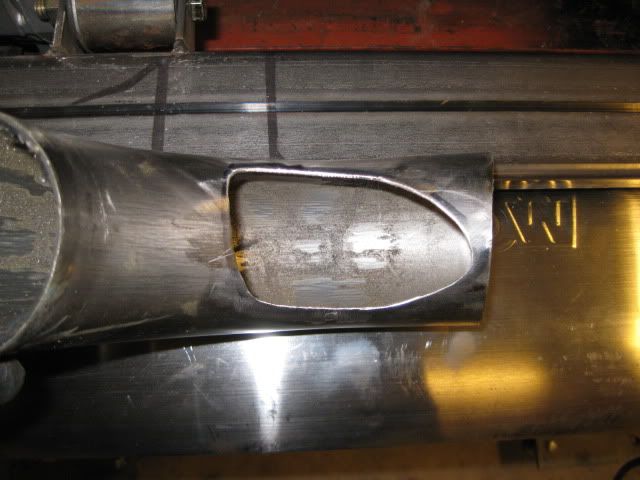
I was also able to finish the rear collector. Maybe on Sunday I will get the V-band clamp installed and the rest of the exhaust welded up.
Very slick flywheel... hard to believe it was a chunk of 6061 Al only a few short days ago. What are you using to attach the wear plate to the flywheel? They look like Phillips head countersinkable bolts. Where did you get them, what grade are they, what torque did you put on the nuts, and did you find it hard to torque the nuts properly with only the Phillips drive to hold them still?
Very slick flywheel... hard to believe it was a chunk of 6061 Al only a few short days ago. What are you using to attach the wear plate to the flywheel? They look like Phillips head countersinkable bolts. Where did you get them, what grade are they, what torque did you put on the nuts, and did you find it hard to torque the nuts properly with only the Phillips drive to hold them still?
They came supplied with the fidanza wear strip, so I can't comment on their details, but I assume they have been proven to work. The nuts have a serration on the backside to prevent them from working loose. The instructions that came with the wear strip specified to torque them to 7lb-ft. I used a vice to hold the flywheel while I use a screw driver to hold one side and an in-lb torque wrench on the other side. My original fidanza flywheel had the counter bores for these bolts at 1/2" in diameter but none of my sockets would fit down in the holes, so I used 5/8" on mine.
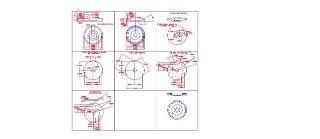
I am sure you are aware, but for the others, this is the amount of work that went into this flywheel. Each box is a just 1 step in the process.
BTW, I sent you an email.
[This message has been edited by fieroguru (edited 04-02-2011).]
Fieroguru, that is a work of art! Nice weight too! I have replaced the fidanza plates before, there was no problems holding the philips head for me either. My plate also came with fasteners, and they looked to be of high grade. I like to use loc-tite on the threads too, just because those are not the kind of bolts you want comming loose.
Work has kept me pretty busy, but I was able to do some work on the swap today. Installed the MLS exhaust gaskets to ensure proper manifold placement, installed the 2nd and last v-band and started to clean up the welds. The end product will be 3 pieces: two manifolds/downpipes and a single Y pipe/muffler/tail pipe section.
The next step is to slide the engine/tranny/cradle back under the car and finish welding the flexible section, the 3" section going into the muffler and the two tail pipes.


 Me likey. This by far seems to be the best design for the F40. Certainly a better design than the flex plate/spacer/flywheel idea. The countersunk hub is going to make finding suitable flywheel bolts easy too, heck, you could use bolts with full thickness heads. Great pics!
 Next stop balancing?