Did you abandon the mechanical water pump manifold you were designing a while back? Are you putting in a different clutch this time? Nice work.
Didn't abandon... just shifting priorities so my car will actually run this year (I still hate electric water pumps). I will likely install a new clutch, but it will be just like my old one. It had great holding power and awesome drivability, so I will stick with it and see if I can find its limit.
If your mechanical waterpump manifold is anywhere near as nice and slick looking as the electric manifold you have on there now, I'll definitely have to get one from you!
Originally posted by Trinten: If your mechanical water pump manifold is anywhere near as nice and slick looking as the electric manifold you have on there now, I'll definitely have to get one from you!
The mechanical version will feed into the backside of the same water manifold used with the electric (with some clearance machining on the backside of the water manifold).
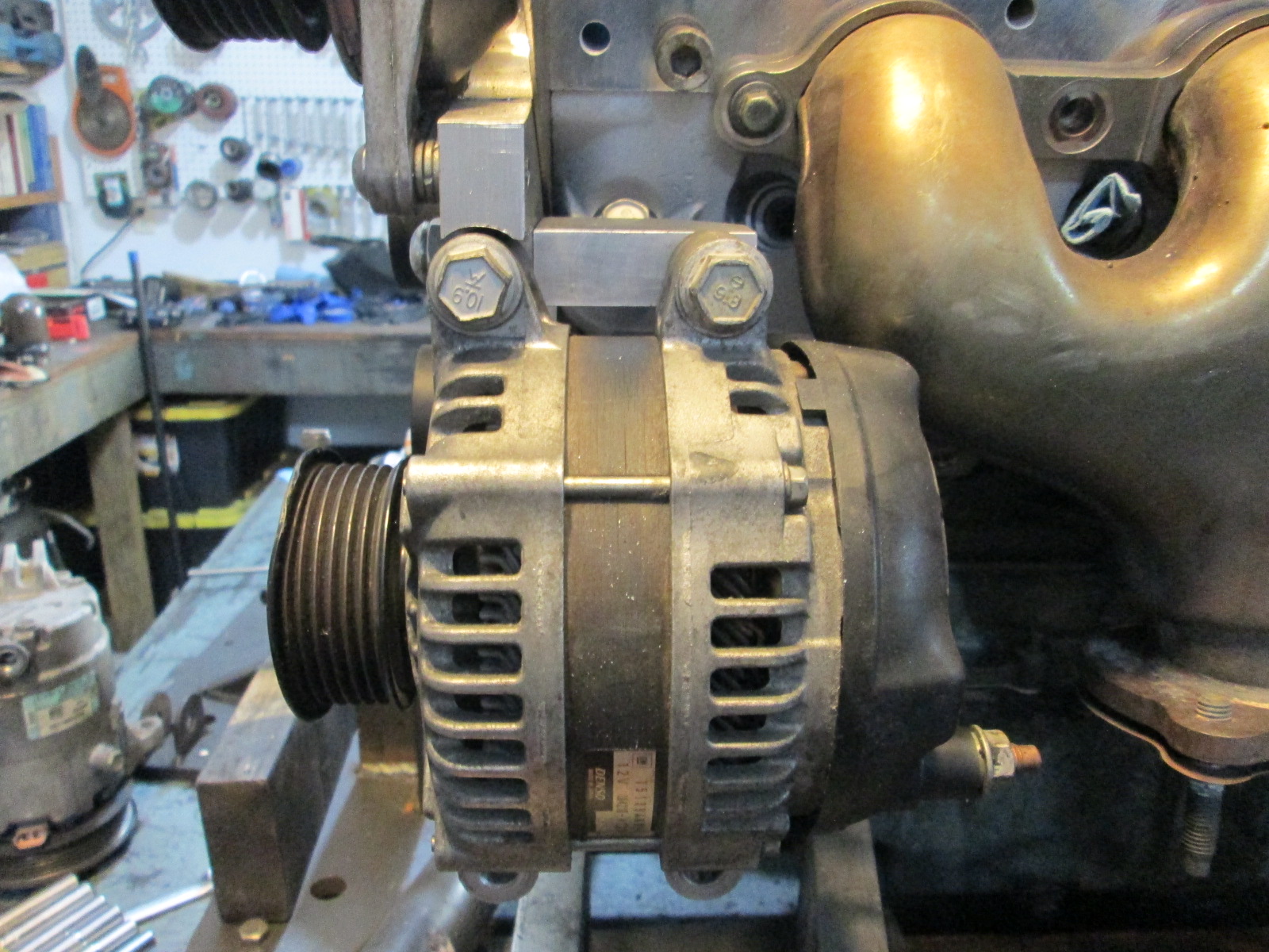
This mechanical water pump setup has been a bit of a rabbit hole more than a few times, but I will eventually get it figured out to my liking. Having the engine mounting location locked down, knowing the absolute highest the alternator can be mounted and still clear the LS4 and LS7 exhaust manifolds will definitely help with optimizing the rest of the setup. It is nice being able to have 1 setup in the car and one on the fixture knowing they are mounted in the exact same position.
Your whole front cover setup looks drastically different than on mine. Mine has this apparently single piece plastic monstrosity that (seemed to) integrate the timing chain cover along with the connections/mounts for the LS4 power steering pump, and of course the mechanical waterpump.
I skimmed back through your thread but couldn't find what timing cover or other alterations you made (besides the power steering pump delete and of course your water adapter). What did you use? I'm planning to be out at Mikes this Saturday, I'll take pics of the thing that was on my engine.
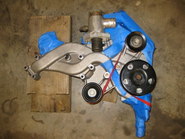
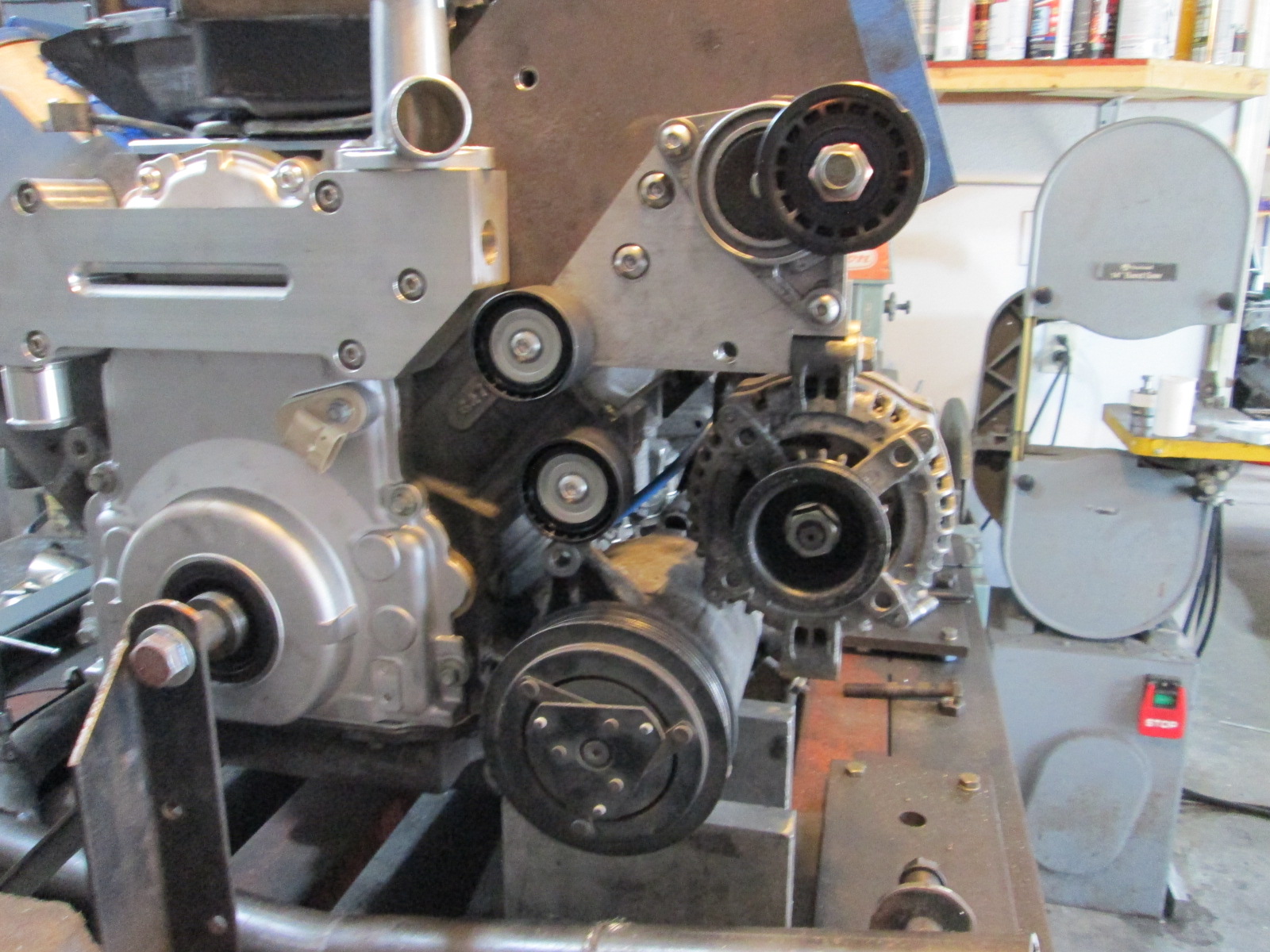
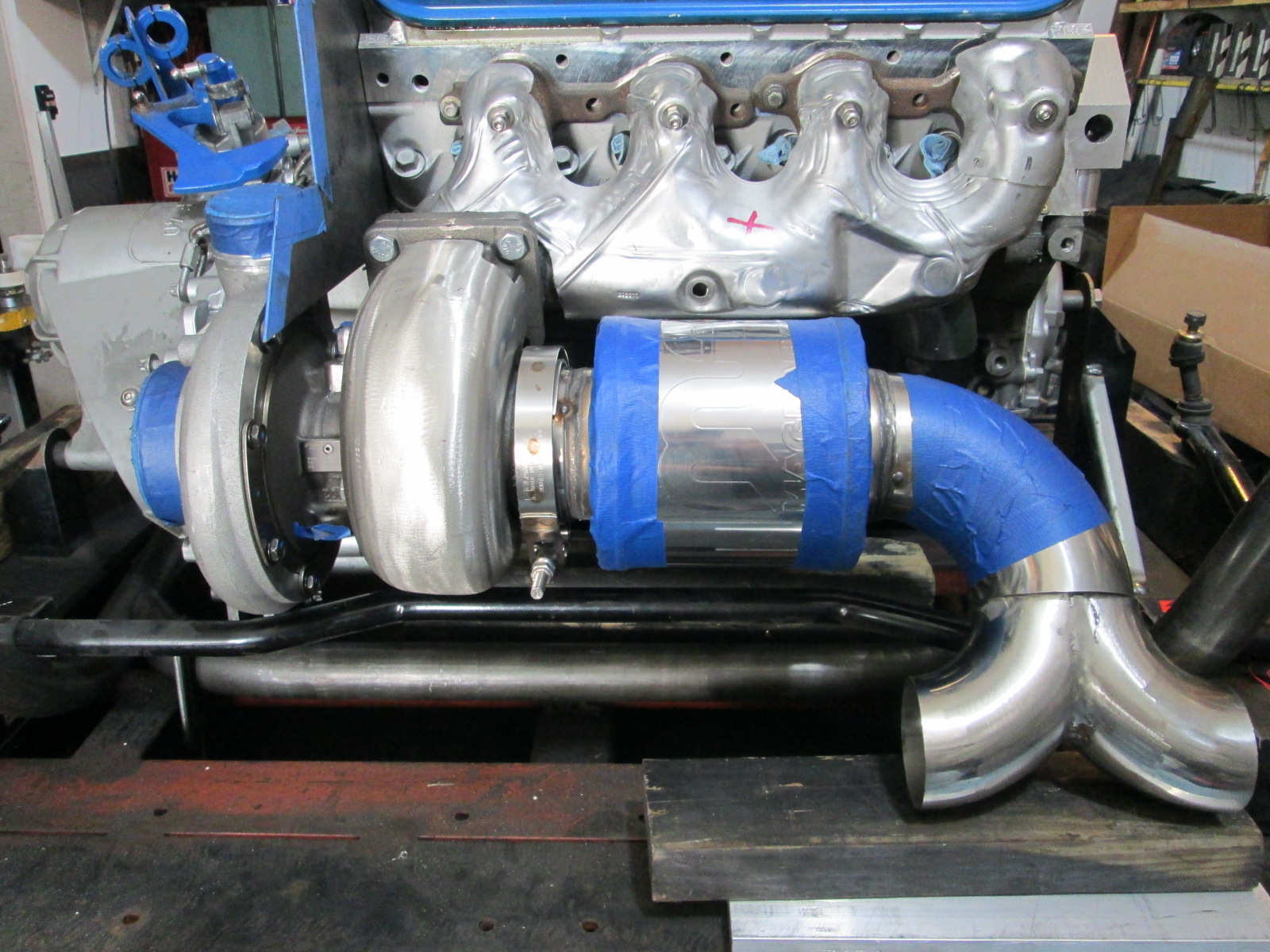
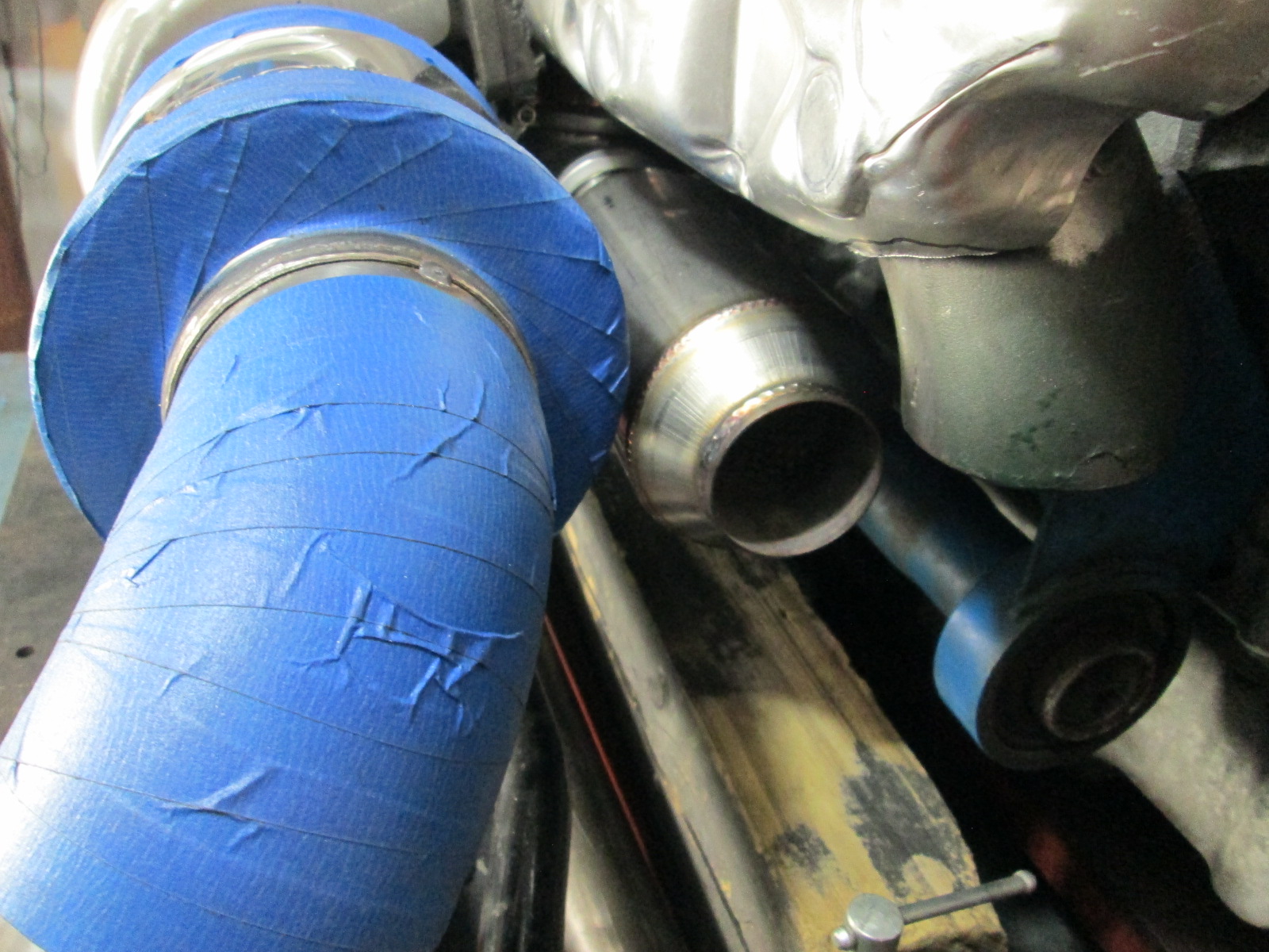
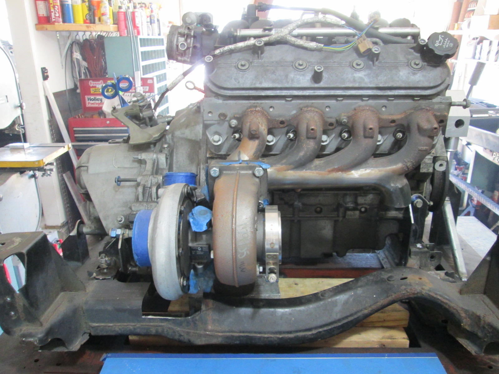
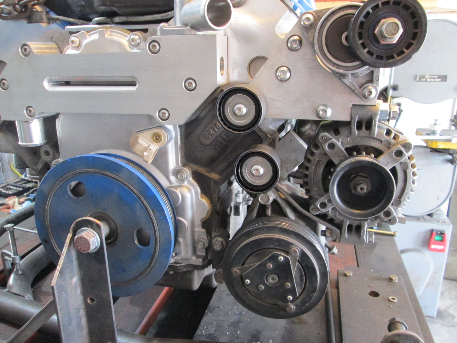
I am sure you have the stock LS4 water pump. It is a huge beast and made from aluminum. For my initial install, I heavily modified it to make room to mount the alternator down low and out of sight. Everything with blue tape was cut away and capped.I removed the stock coolant fill, the coolant inlet tube, thermostat housing area, as well as the coolant exit and reworked all of those areas. I added back a new thermostat housing, coolant inlet nipple as well as a mounting point for the tensioner. It was a huge amount of work, and not something I really want to do again. It should be faster to just make the new mechanical water pump than modify the stock one like I previously did.
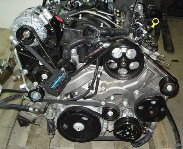
Here is the stock LS4 accessory drive with the stock water pump setup:
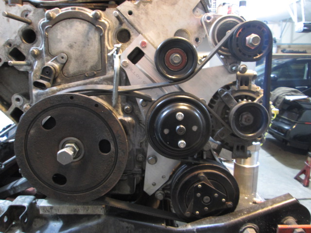
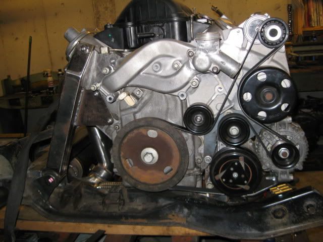
Here is what my first swap ended up looking like with the highly modified stock water pump:
Man, once that CNC table is up and running, cranking out brackets and the like is going to be so much faster for you (well, okay, with whatever programming is involved, maybe not faster, but at least not as labor intensive?)
Man, once that CNC table is up and running, cranking out brackets and the like is going to be so much faster for you (well, okay, with whatever programming is involved, maybe not faster, but at least not as labor intensive?)
Everything is looking sharp, as always!
The programming is also a one time investment though, once done the first time, all he will have to do is drop the file and click go. Also, the programming aspect isn't too time consuming if you already have a .DWG of the file you intend to cut.
------------------ "I am not what you so glibly call to be a civilized man. I have broken with society for reasons which I alone am able to appreciate. I am therefore not subject to it's stupid laws, and I ask you to never allude to them in my presence again."
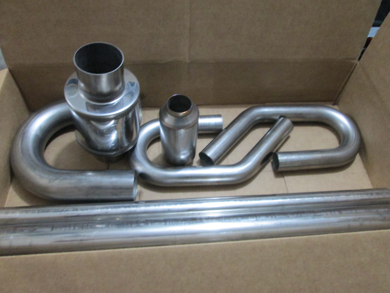
The 3.5" Magnaflow muffler, 2" waste gate muffler, assorted 3" and 2" exhaust bends arrived this week. I haven't done much with it...
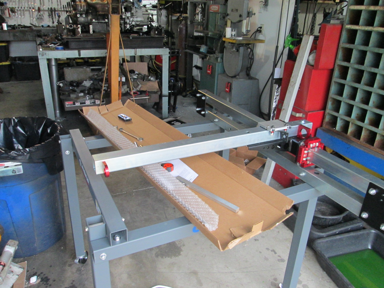
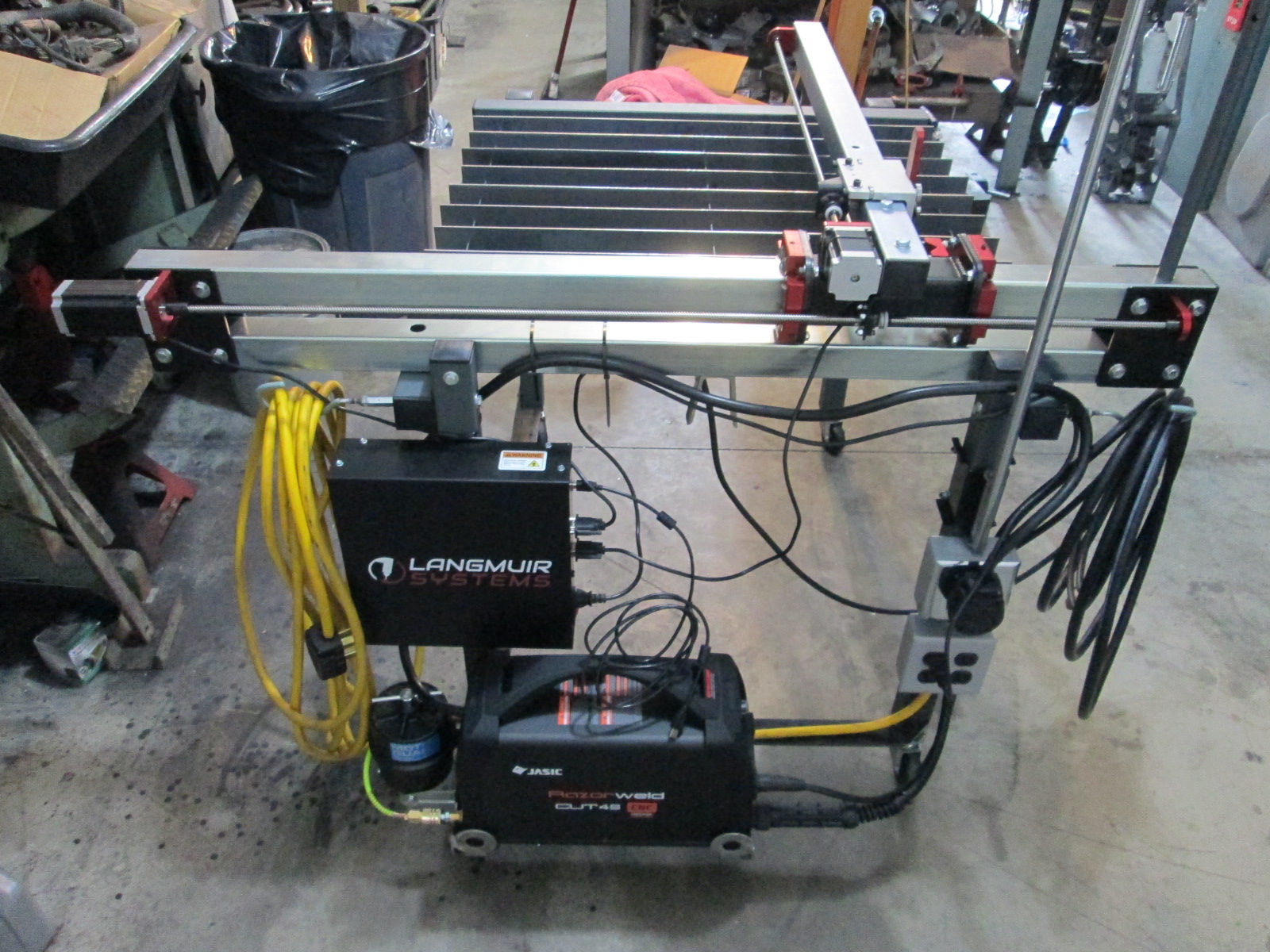
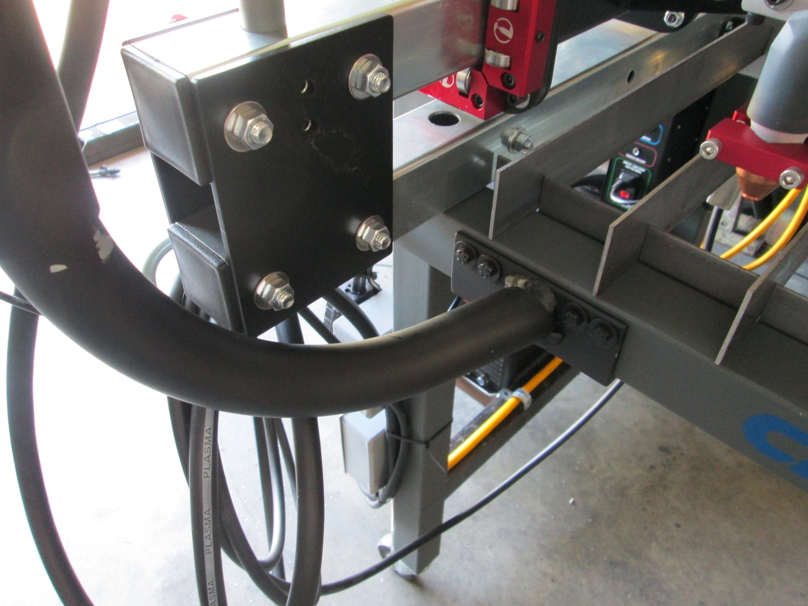
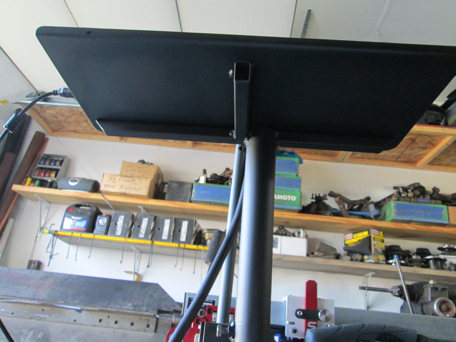
The plasma table is nearing completion of the assembly process (except the water table that is back ordered). I completed most of the normal assembly last week, but this week I was focused on other modifications. The primary goal is to have this table all self-contained, so I set the laptop on it, plug in the 220V cord, plug in the air line and get to work. Here is the list of modifications:
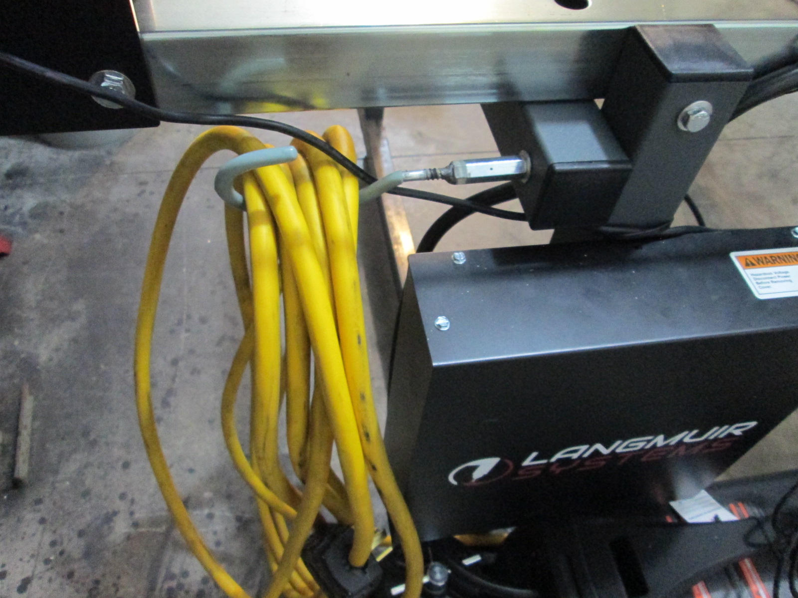
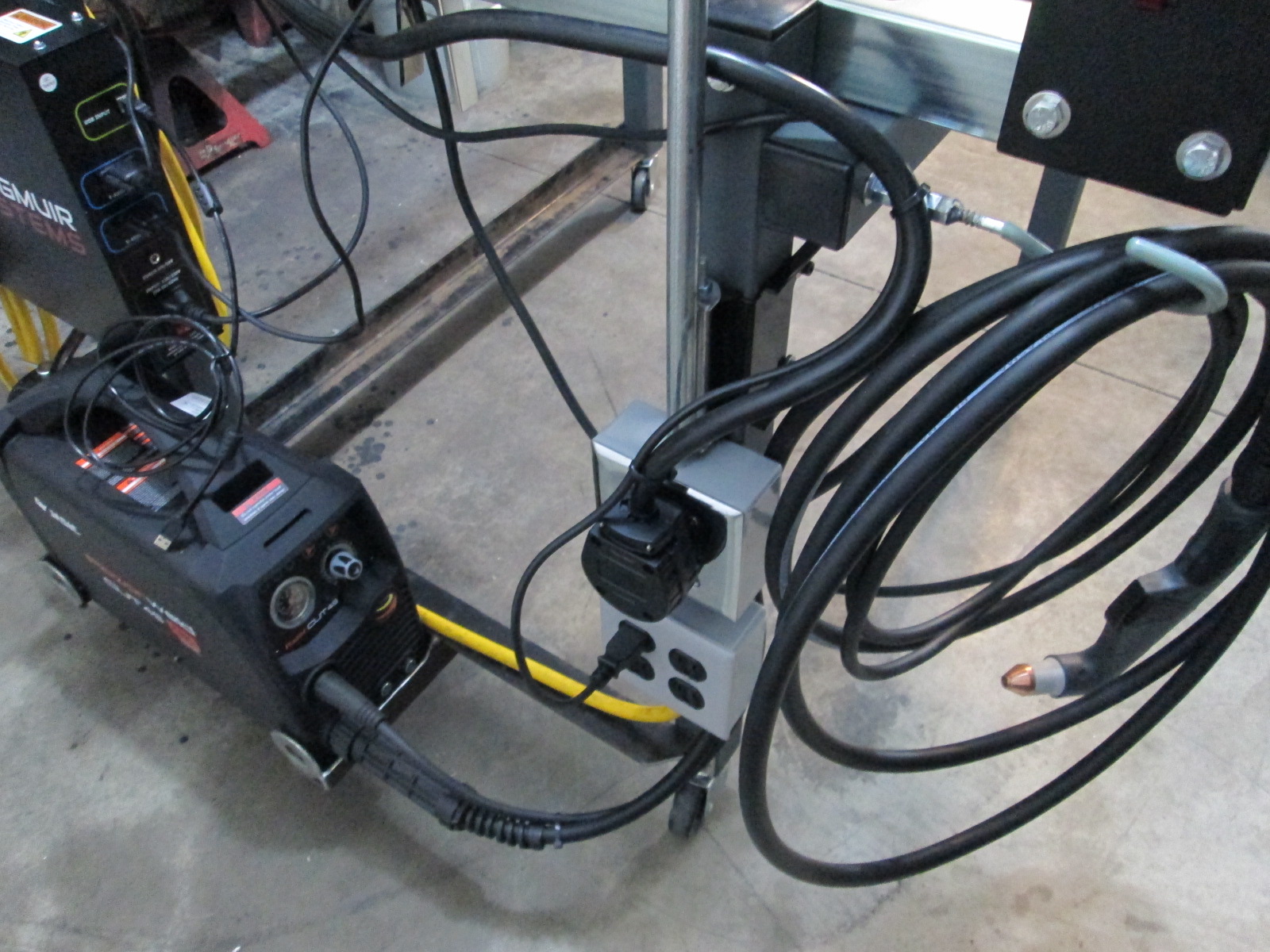
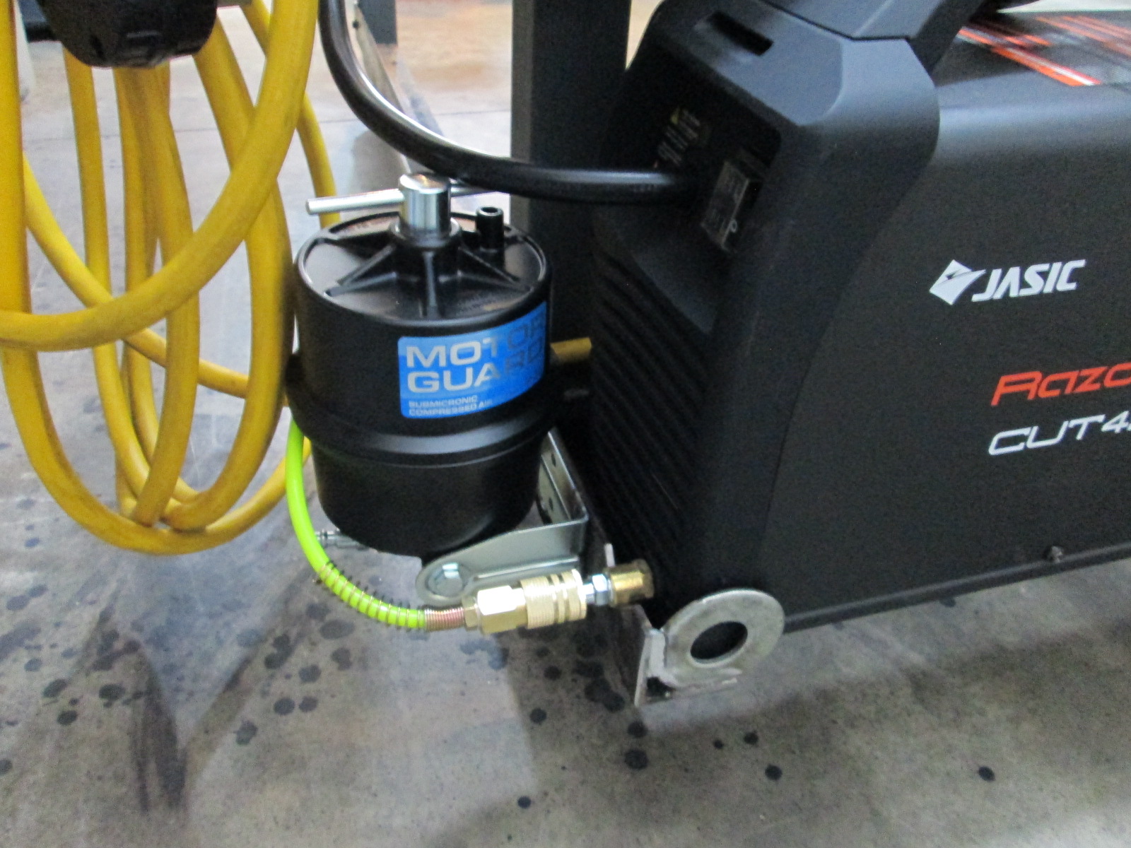
10 ga power cable for the table. I didn't measure it, but kept it long enough to have the plasma table in the driveway with it plugged in. Installed 220V plug receptacle for the welder. Installed four 110V outlets (1 for the plasma table controller). Mounting bracket for the plasma cutter so it moves with the table. Mounting bracket and plumbing for air filter - this housing has the quick disconnect fitting for the air line. Added two cable holder hooks. One for the 220V plug in cable, one for the plasma cutter cable and ground wires. Modification still underway for the laptop stand. The supplied brackets had it about 12" too low for me. It is also at too steep of an angle and does not include space for a mouse.
I still need to: Clean up the wiring with better cable supports than wire tires - probably will use some conduit clamps once I have everything where I like it. Come up with some kind of smal tool box for all the consumables (tips, electrodes, heat shields, spare filter, etc).
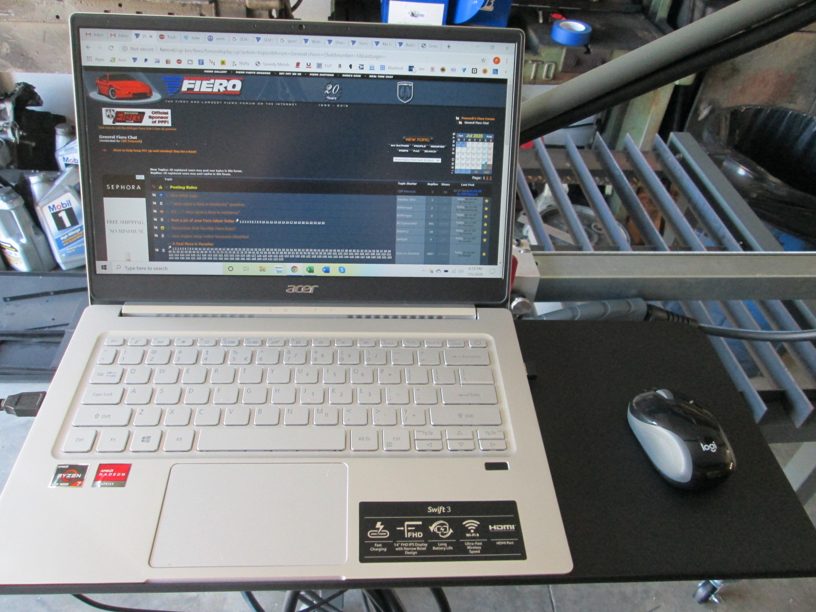
I also settled on a new laptop for this machine, it should be here Wednesday, then I can load up the software.
Hi Everyone, Senior Guru, I think this is my first post. I have been trying to get registered on the forum here for a while, and must have been registered before. After fighting with my tablet or phone for the last 2 weeks, I finally got signed in by going to the laptop with a keyboard..
I have been reading your build thread here from start to now for the last month solid, but I am not sure where to find some little details I may ask about later. I LOVE YOUR PROJECT!!!, I pretty much want to do everything you did to your car, to mine, when I finally bring it home, and buy as much of the stuff as I can from you, I will start ordering parts after my car is here, as budget allows. It's a little like your 2 Fieros rule with your wife. I have to get rid of a couple cars around here before I can bring home another. I have 5 NON-running projects(4 at home, 1 in storage with 2 extra parts cars at home), and a couple running hotrods at the house too, then the daily drivers, and a few cars that belong to friends of mine, and about 6 different trailers. I live on 7/8 of an acre, but there are a lot of cars here.
I am getting an 88 V6/auto car, don't know what it originally was, though i will find out soon. It has a Ferrari 328 GTB body kit on it, Red (Think Magnum P.I. from the 80s). I will put up some pictures In a day or 2. I have been talking to the guy about this car for 6-8 years, and he finally told me I can have it (for a good price finally). I had 2 questions at the start, do you know of any F40 failures? (from too much power or torque) I would like to bore an LS4 to LS1 size and stroke it to a 383 with a 4 inch crank. That gives us the other question, which I know you had something in the first couple pages, I WILL find it, If you don't want to bother answering, What are the crank differences from LS4 to LS1 / LS2 ? (I would be going 24x, and I bought the Goodson 200.00 tool years ago, I like your solution better for that by the way)
I really like the way you completely share with everyone what you are doing, and detail everything so well, too, this is all awesome..
Frank, welcome to the forum and thanks for the compliments!
quote
Originally posted by Franked: I had 2 questions at the start, do you know of any F40 failures? (from too much power or torque) I would like to bore an LS4 to LS1 size and stroke it to a 383 with a 4 inch crank. That gives us the other question, which I know you had something in the first couple pages, I WILL find it, If you don't want to bother answering, What are the crank differences from LS4 to LS1 / LS2 ? (I would be going 24x, and I bought the Goodson 200.00 tool years ago, I like your solution better for that by the way)
There have been a couple, but those failures were a little odd. I am not aware of a single F40 failure behind any LS engine and there are plenty well north of 400 hp and 400 lb/ft. I am hoping to NOT find the limit with my turbo upgrade.
If you bore the LS4 to 3.898", the sleeve thickness will be about 0.066", which is about 0.010" (14% thinner) than a stock 6.0L sleeve. Assuming the block starts out true, it should work for sub 500 hp levels. There is a group that is taking the LS4 block, cutting out the sleeves and installing new wet sleeves to increase the bore, but it isn't cheap.
The LS4 crankshaft is 13mm shorter than a standard LS crank (stroke is the same between LS4, LS1, LS2, LS3). 3MM on the flywheel end, 10mm on the balancer end. The 10mm extra on the balancer end is a non-issue as the LS4 crank doesn't fully protrude the LS4 balancer to begin with. Lots of Porsche swaps use the LS4 balancer on LS1, LS2, and LS3 engines w/o any machining. The flywheel side is also not a major deal. Some have turned the end down the 3mm (0.118") to match the LS4 crank. Another option is to make a spacer plate to shift the transmission 0.118 (1/8" is close enough) away from the block. This keeps the same ring gear placement on the flywheel relative to the transmission which the starter mounts to. At that depth, the stock dowel pins will keep it aligned, so just some aluminum 1/8" thick flat bar with some holes will allow you to install the crankshaft w/o any additional machining. If you mount the starter to the bottom of the oil pan (Moroso), then you will need to remove the 3mm from the crankshaft to keep the ring gear close enough to the starter.
Thanks for the full on response.. I have one of those engines with the Darton sleeves, bored to 4.125, with a 4.1 crank, giving me a 7.2 liter or 438 ci I put it together about 2&1/2 years ago, and never went beyond that. We bought a different house, major remodel, moved in last year, still making it our way (the house) and some of the other projects came first before my el camino gets done with that big LS. I need to do some learning on HP tuners before I try to tune that one anyway. Working on a pic.... I will start my own thread when I get the Fiero home, which may take a month or more.
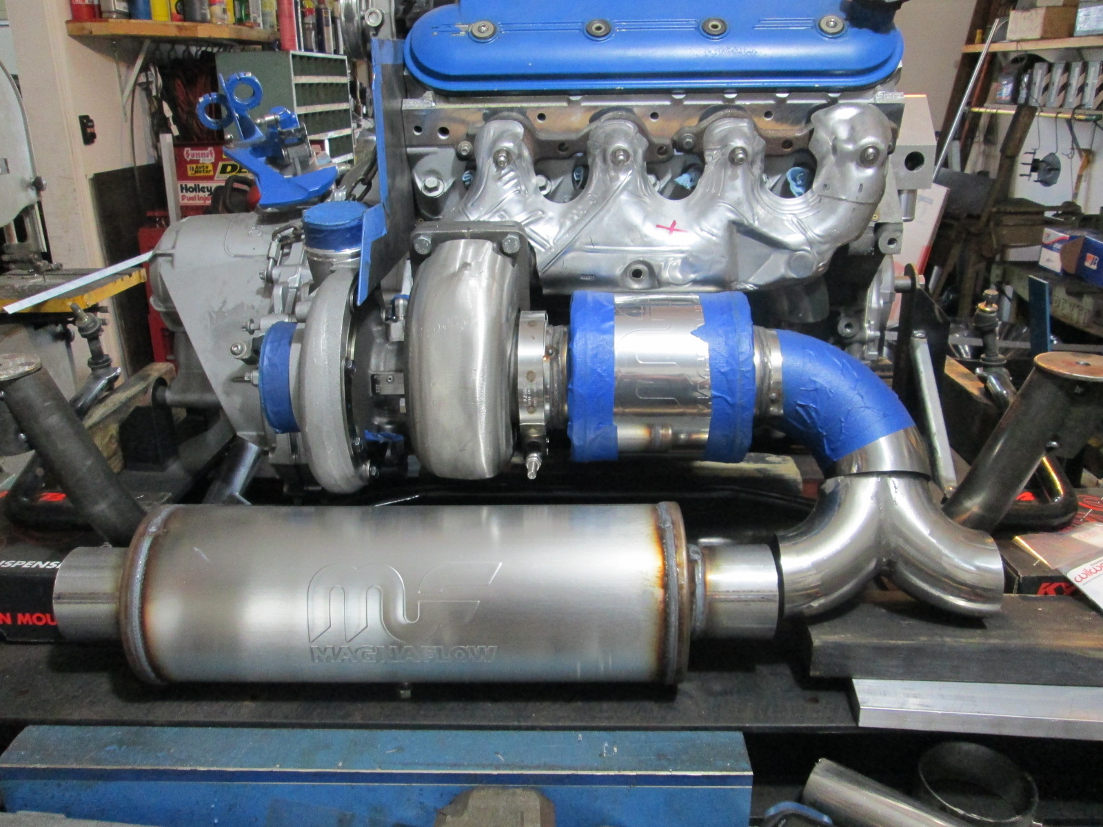
Started mocking up more of the exhaust. This is the general location of the 3.5" muffler, the 3" Y and the wastegate muffler. The current plan is to merge the waste pipe back into the 3 1/2" 90 before the Y split. It will be tight routing the wastegate pipe around the front bank exhaust pipe entering the manifold, but I am sure it will fit.
The 3" Magnaflow muffler should be here this week, so I can start placing it. The next major step for the rear portion of the exhaust is a test fit to make sure everything clears the trunk wall, but to do that the engine needs to be supported by the cradle (front crossmember, engine/transmission mounts, and accessory drive...)
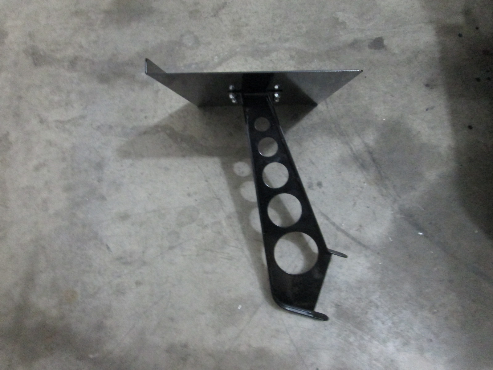
I did make the 2nd part for the upper alternator bracket:
I have also been working on the plasma table, activating a new laptop, and loading software. The table and controller work as expected! Here is a short video of the table cycling through its break in process where it goes to the limits of travel about 40-50 times. This is a supplied program, but only cycles the machine from 0,0 to 23,23 and with the XL upgrade it should cycle it from 0,0 to 24.5,32.5. This will likely be the first G-code I update so I can break the table it as the full range of travel.
Overall with the XL kit, there is about 25" x 33" of usable space, which is pretty good... but I can't help myself and started to explore why the limits are what they are. I don't want to have to source new lead screws, so my primary focus was how much travel was left on the table using the existing feed screws and motor/bearing mounts... several inches in both directions.
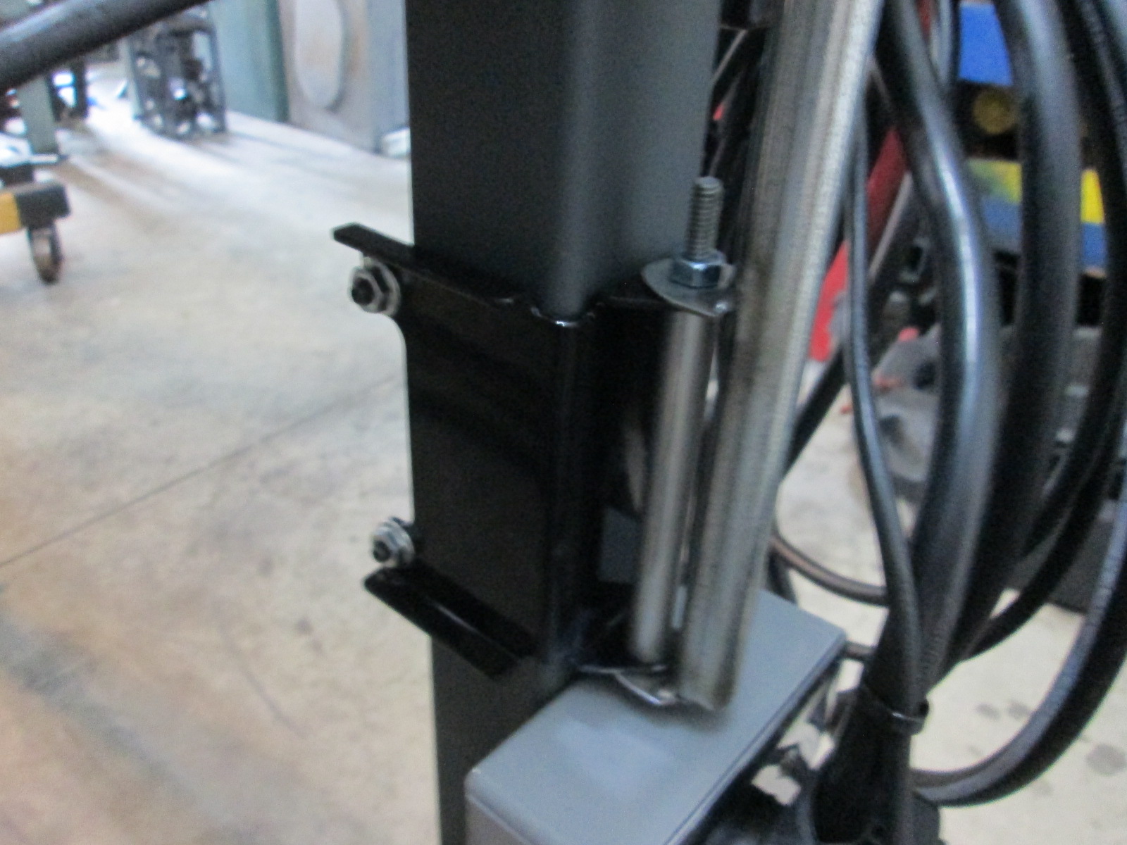
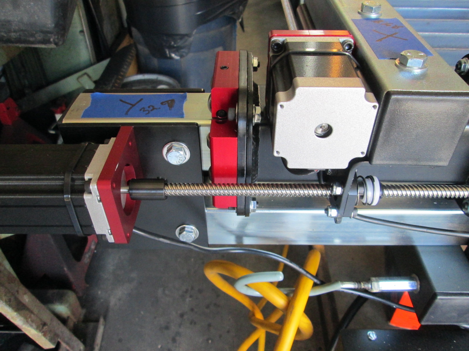
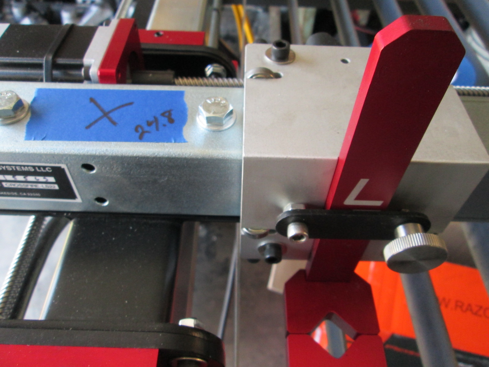
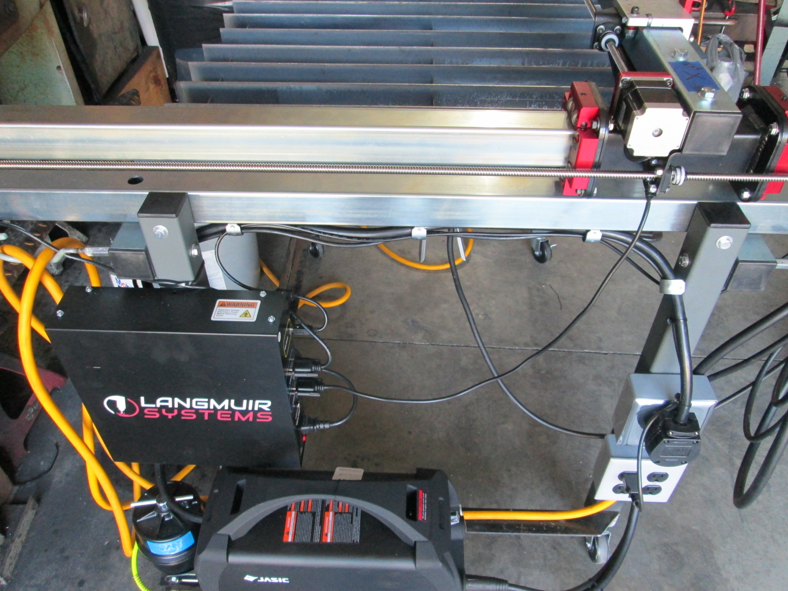
The Y axis is the longer of the two. Here is a picture of the gantry carriage at the motor end. The first point of limiting travel is the plate that bolts the upper rail to the lower rail. There is no reason these rails couldn't be longer and the plate reworked to shift them further away from the carriage, while leaving the motor support in the same location. This would allow the carriage to get within 1/4" of the motor mount bracket and add a little more than 2" of travel.
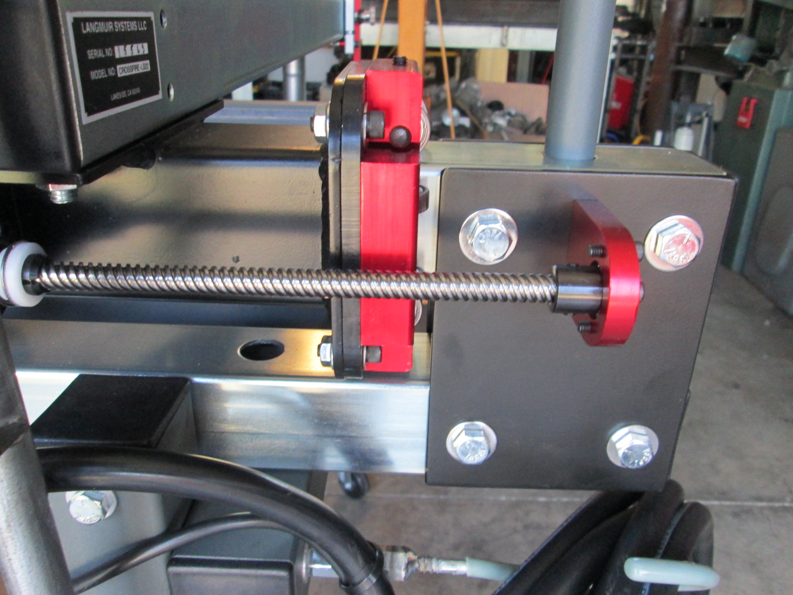
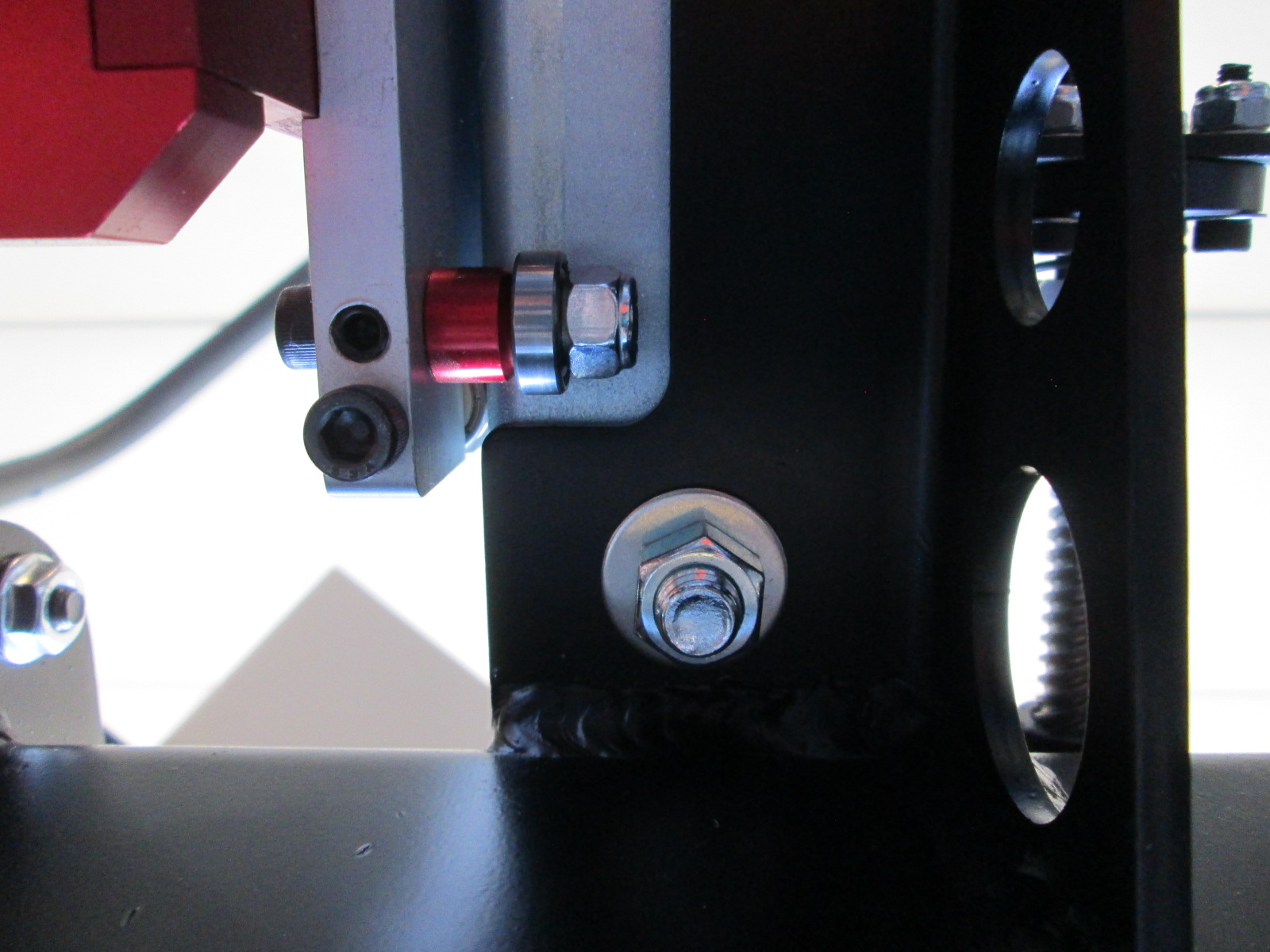
At the other end, we have the same issue. Travel is limited by the length of the square tubing and the placement of the rail mounting brackets. Move these so the bearing support bracket becomes the point of interference and you can likely get another couple of inches of travel. So overall there is 4-5" of additional travel available w/o changing lead screws... That would raise the spec to 37 to 38" which is just above 3'.
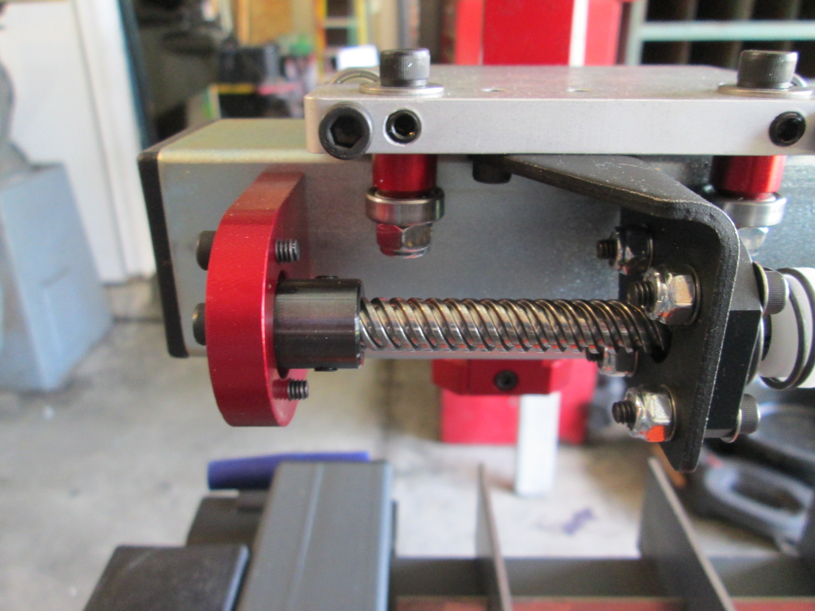
The X axis also has some opportunity, but not as much. The far end the travel limit is the roller contacting the lead screw bearing support. This is in the way because it mounts to the side of the tube. If it is rotated 90 degrees and a new plate is fabricated and mounted to the bottom of the cantilevered beam, then the bearing support mounted to this new horizontal plate, then these modifications would allow the carriage roller to reach the edge of the tube, gaining 1.5 to 2 inches.
The other end takes a bit more work and would only get you about 1" more travel. On the top side, the carriage runs into the bolt head, but there is about 1/8" of clearance between the carriage and rail. So installing a counter sunk bolt in this hole would improve clearance on the topside. The bottom side support bracket for the cantilevered rail has a cutout to clear the carriage rollers. This cutout needs to be extended
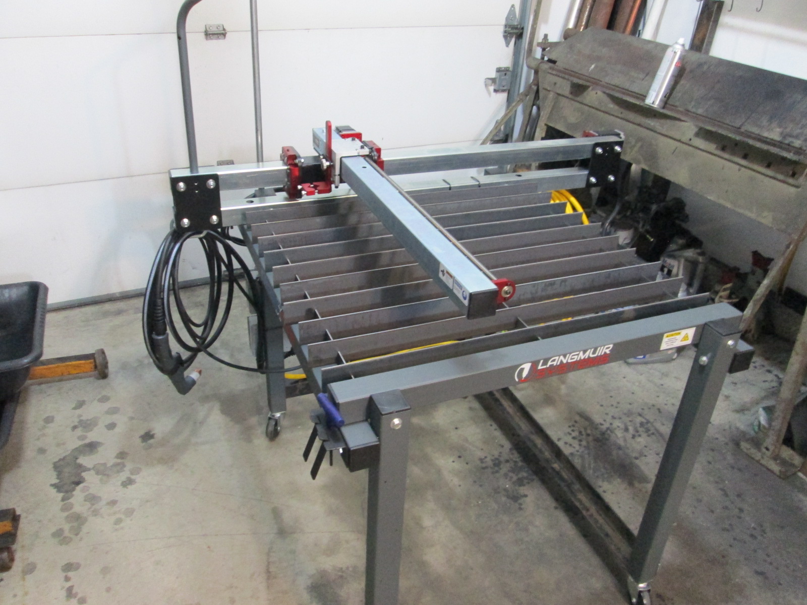
So far I am pretty please with the system. The one gripe I have is with the optional laptop stand... It was made to be used with a chair, and I simply don't have any extra room for a chair. So I modified it to be at standing level. Then I ran into another issue with it... The Right/Left arrow keys are used to move the torch head along the X axis and the Up/Down arrow keys move the torch along the Y axis. To help make things more intuitive, the laptop screen should be parallel to the X-axis so the keys point and move the torch in the same direction. The supplied laptop stand has the screen parallel to the Y axis and only allows about 45 degrees of rotation. So I will be modifying the laptop stand yet again...
[This message has been edited by fieroguru (edited 07-04-2020).]
I went ahead and made a completely new laptop stand that positions the laptop so the arrow keys match the torch movement. The top part is wider to allow room for the mouse, is horizontal so the mouse doesn't roll around, can be rotated (locked in place with the clamp bolt), as well as be removed. It bolts to the lower rail as I didn't want to bolt it to the rails that support the cantilevered rail - didn't want to move the torch up/down when I worked on the laptop).
Overall I am pretty happy with it....
Also cleaned up the wiring with some strategically places conduit clamps and added a plastic cable support for the X-axis servo wire so it won't rub on the frame.
Not much actual work progress this past week... the day job has me swamped with July being the highest production volume of the year and I have about $600K in projects being installed and started up during this peak.
My water table has shipped so it should arrive later this week. My 3" magnaflow muffler shipment was cancelled through Amazon (not sure why), so I ordered it through Summit.
I did mess around with Fusion 360 some, but didn't really like it much. It has way to many features which just makes things overly complicated. I might use it more if/when I get into CNC machining parts.
Sheetcam doesn't have all the 3D features of Fusion 360, but they are not needed for plasma cutting. So I downloaded the software, watched about 5 tutorials on YouTube. Everything is pretty intuitive with Sheetcam, so that is what I am moving ahead with. The next step is to make some .dxf files to import.
I already have AutoCAD and have my entire product line detailed in digital files. So all I had to do was make a separate .dxf files for each individual part to be cut. Basically all the hard work to document every detail was deleted down to the base part geometry (saved as a new file, keeping all the prior work). Now I have all my current parts as .dxf files and a test cut file.
To cut precision, high quality parts that need very little cleanup, I will need to determine the optimal settings: air pressure, amps, travel speed, tip diameter, etc. for the various material thicknesses and material type (steel, stainless, aluminum etc). There are general guidelines and suggestions for starting points, but every system is a little different. To help dial in these settings (starting with 10ga mild steel) I drew up some test geometry that I can cut with the different settings to see what I can expect the final result to be. It is about 6" long, 1" wide, with 1/2", 3/8, and 1/4" holes, and inside and outside sharp corners. This test file covers most of what I need the machine to do so once I am happy cutting this shape, then cutting the rest of my 1/8" steel parts will a non-issue.
I haven't started playing with cutting material yet, primarily because I don't want to do it twice. The water table helps cut down the fumes, but more importantly is splashes water on the backside of the metal plate being cut, this helps keep the material cooler, results in less distortion, and smoother overall cut quality. So once the water table is here, I will start cutting some metal... maybe have something to show next weekend.
Day job continues to be super busy and there was an influx of LLC orders to process this week as well. All that means is not much else happened...
The 3" muffler came in, here is a general mockup.
The water table came in, so I got it installed. Here is a video showing the torch head going the same direction as the arrow keys.
Here is a video of the tool travel path for my test cut program. Now I am ready to fill the water table put some metal on the table and do some cutting!
Originally posted by pmbrunelle: Cutting coilover strut hat plates with this new tool yet?
No plans to cut those. By the time you cut them, cut the tubing, source the bushing, and weld/paint, it is faster and more economical to continue to use the off the shelf KYB strut hats.
Been working 60-70 hr weeks for the day job. I am in the middle of about 5 large startups/installs. Last week 2 went into live production, 3 more will go live in August, plus it is the busy season and there are lots of other new initiatives to get going...
I did take a few hours today and play with the plasma table. 2 steps forward, 1 step back... Table works and cuts but there are two issues I need to research.
The torch and air stays on too long at the end of the cut.
I ran the program 3 times and 2 of the 3 didn't cut right. One missed a hole (torch didn't light off), the other missed a hole and cut during a transit move (so the torch didn't shut off).
I think you mentioned using an electric pump for this install. Are you going to have a few water manifolds made? Does your water manifold have a T-stat in it?
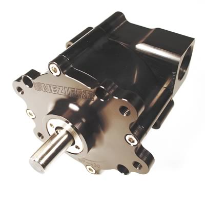
Meziere has remote mechanical pumps. I'm not sure how new they are.
Great work as always Mr. Guru. Question for you: I had been planning to use an MT2 F40 for my Fiero, but I'm seeing a lot of MR6 transmissions out there coming out of the turbo Buick Regals from 2011-2013. Other than a higher 1st gear ratio, it looks pretty similar to the MT2. Do you know of any reason the MR6 would not be a good choice?
That looks correct! I found another thread, incidentally with guru posting in it as well, and he said "So Yes, you can align the Ecotec engine to the GM Metric transmission by using the dowel pins... but will result in the engine and transmission being rotated from each other by 6.82 degrees." So, I assume the opposite would be true, that you can install the ecotec F40 to a GM Metric engine, but it will need to rotate 6.82 degrees. So then my next question is, aside from re-drilling the bellhousing bolt holes, are there any other complications that the 6.82 degrees would create between an LS4 and the F40?
[This message has been edited by Bob2112 (edited 08-14-2020).]
Originally posted by KissMySSFiero: Are you going to have a few water manifolds made? Does your water manifold have a T-stat in it?
Haven't found a shop that can make them in the needed price point to be viable, but haven't given up... just haven't had much free time to devote to them. Yes, my water manifold is an all in one unit. Inlet, outlet, heater core feed, coolant fill, and thermostat.
quote
Originally posted by Bob2112: I had been planning to use an MT2 F40 for my Fiero, but I'm seeing a lot of MR6 transmissions out there coming out of the turbo Buick Regals from 2011-2013. Other than a higher 1st gear ratio, it looks pretty similar to the MT2. Do you know of any reason the MR6 would not be a good choice?
quote
Originally posted by Bob2112: So then my next question is, aside from re-drilling the bellhousing bolt holes, are there any other complications that the 6.82 degrees would create between an LS4 and the F40?
Option 1: use the MT2 version. Bolts directly to the F40 and several vendors sell mounts, shifter bracket, clutch line connection, that have been proven to work with at least 1 person racking up 55K miles on the swap.
Option 2; use a transmission that will not directly bolt up. Since there isn't any extra material in the engine or transmission bellhousing flange to allow a simple re-drilling of holes, you will end up needing extra brackets and machining all to end up with a bolted interface that might not be as as strong. It also has different bolt hole locations for transmission mounts and shifter brackets and a different clutch line connection - so you loose current vendor support. Any rotation of the F40 to the LS4 will either require the engine to sit higher, or put the tripot even closer to the LS4 block (which already needs clearancing).
Originally posted by Tom Slick: I NEED THIS FOR MY CAR!!! Make another for me.... lol...
Me Too!
I need to get this all done and tested before I even think about making more. Also not sure there is room with the larger automatic case in the area the turbo sits. Definately would have to relocate the wastegate.
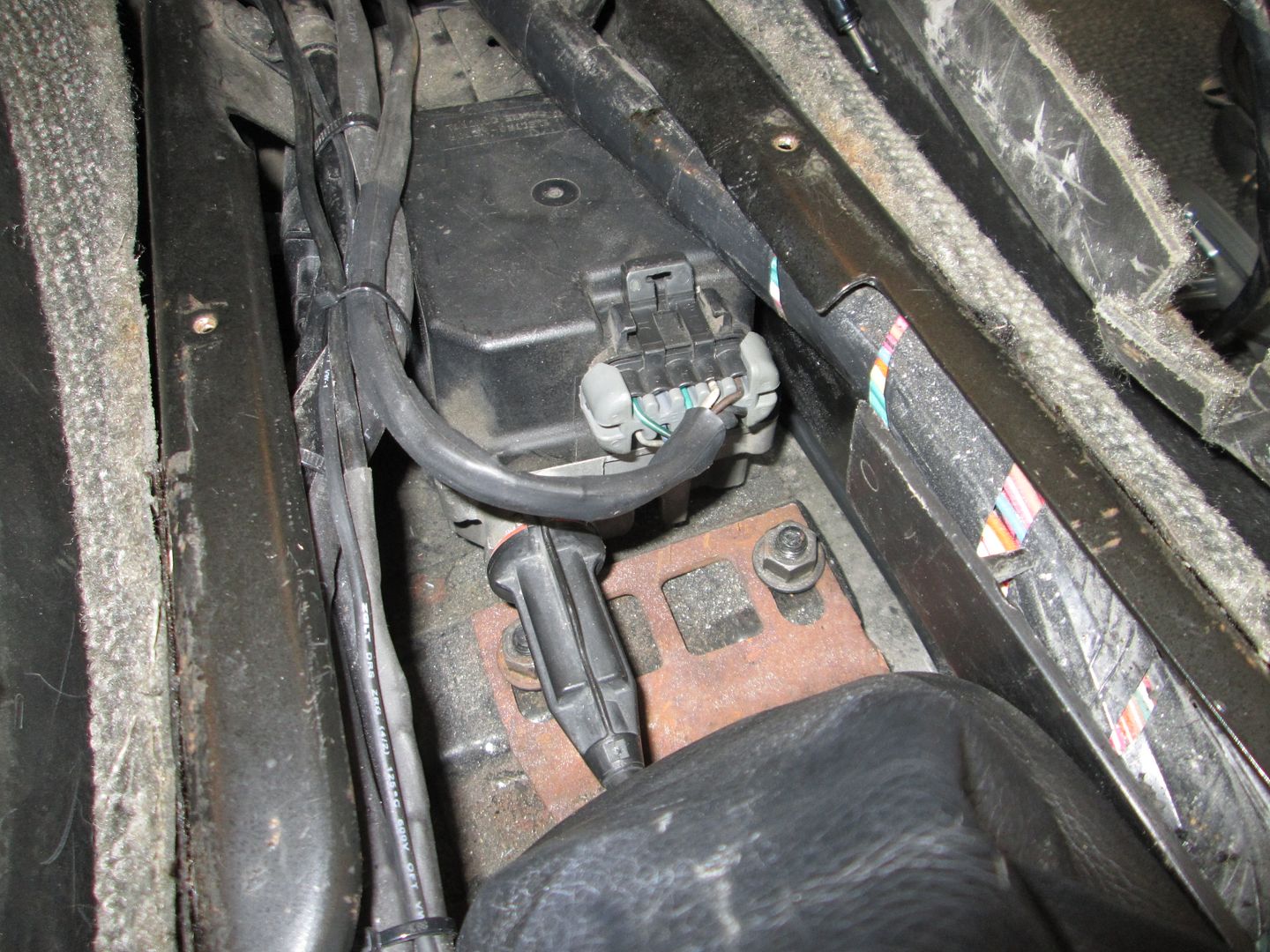
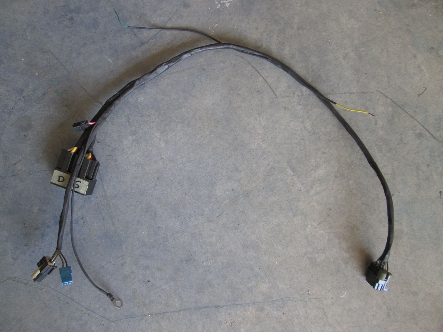
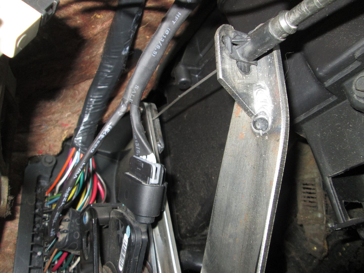
Relocated the AR cruise module to the center tunnel area ahead of the shifter. I ended up building a newer/shorter harness and utilized the on/off switch on the stalk to enable/disable power to the relays. This way they only click when I press either the brake or clutch pedal when I have the cruise "on" vs. anytime the car is running.
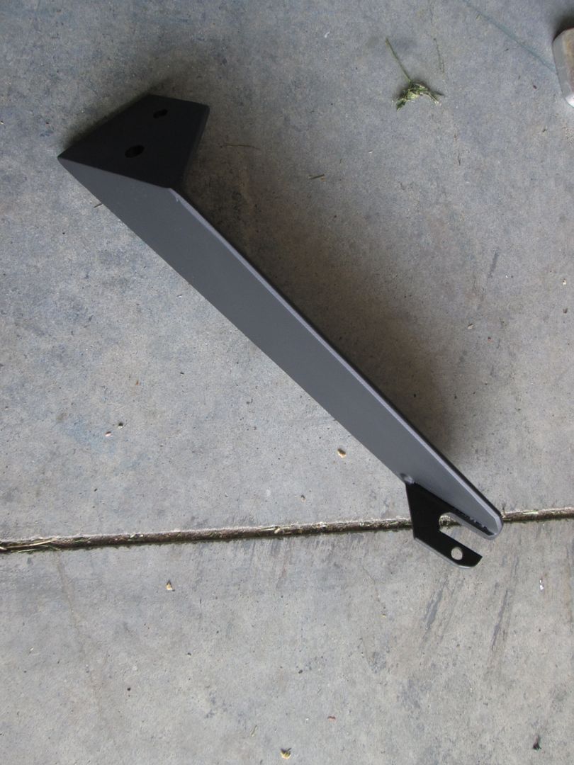
Reworked the pedal bracket to give me more toe room and then painted everything:
I want to add CC to my car and I’m gonna have to do it like you. Do you have any pics of the pedal on how the cc cable is attached. Also, the way you have it wired up. Is the cruise only on and off? I mean does the other settings on the stalk function as is.
Edit: can you make me a harness?
[This message has been edited by Tom Slick (edited 08-31-2020).]
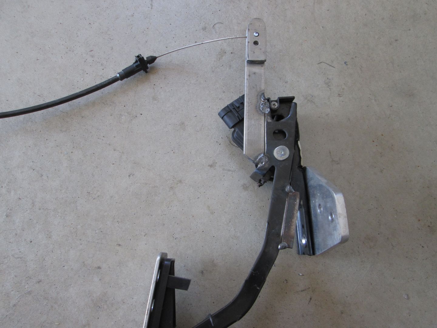
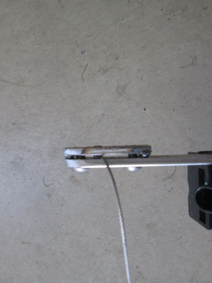
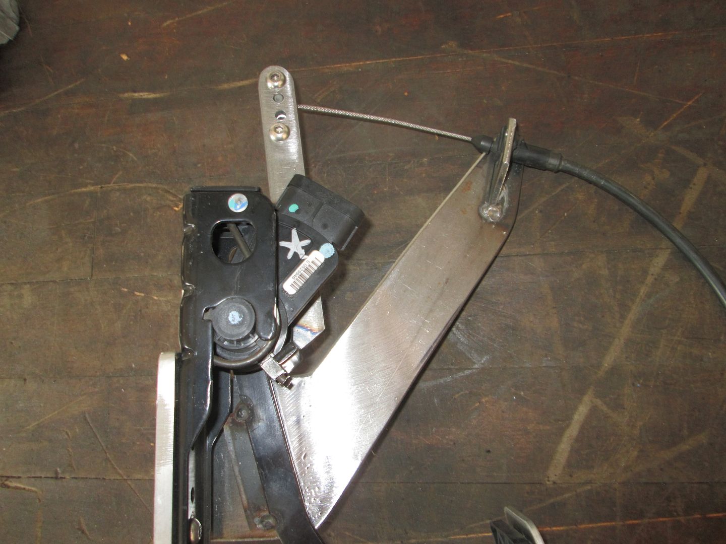
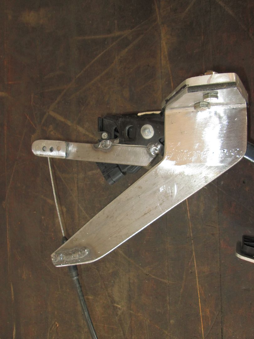
Here are a few more pictures. Basically just tack weld some 3/4" x 1'/8" bar to the pedal. Drill 4 (or more) holes on the end and through a short section of bar as well. The two bars are spaced about 1/8" apart, which creates an opening for the cable to slide into and the barrel end of the cable fits in the holes on both bars.
The multiple holes were to adjust the gain between the cruise and pedal, but I just ended up using the top one.
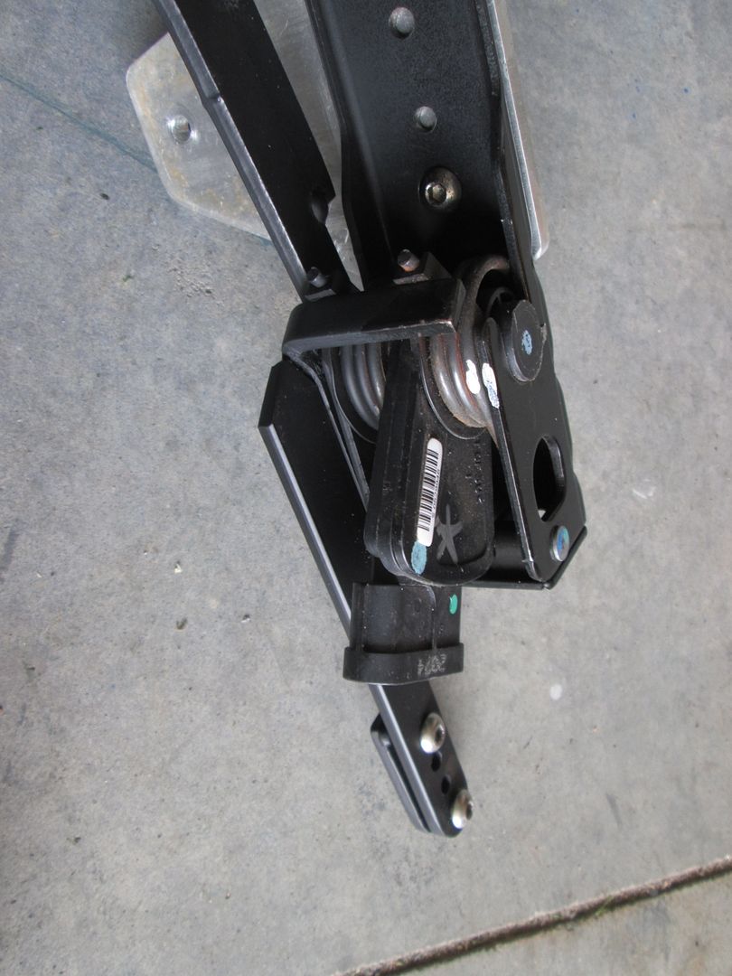
Here is the cable sleeve attachment point. It is just some 1/8" metal in a C shape that accepts the slot in the cable end.
This is an old picture of the cable sleeve arm. It is too thick down at the attachment to the factory thottle pedal mount so my foot would hit it. In the later version, I attached metal along the top side of the support and cut the lower portion away.
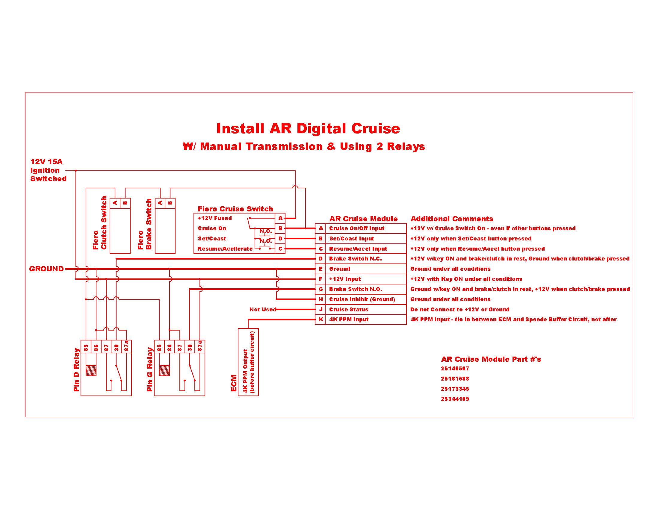
Here is how I wired it up - it just uses the stock cruise stalk, nothing else from the stock Fiero cruise setup. I used the same switch on the clutch and brake wired in series, so it didn't matter which pedal I pressed and the cruise would disengage. All functions worked with the stock stalk, on, set, accel, coast, resume, off.
[This message has been edited by fieroguru (edited 09-01-2020).]