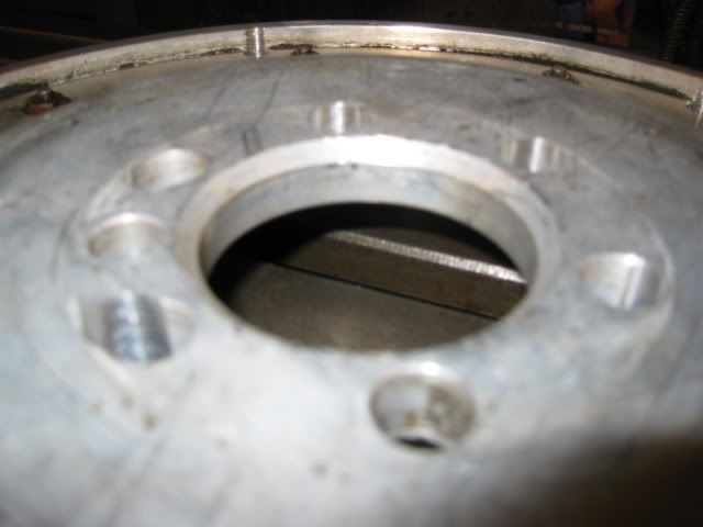
You can't mill the crank side. The original spacer has a recessed pocket for the crank flange to slide into, then it steps down to allow for the crankshaft flange extension on the other side. The crank flange is somewhere around .380" deep and the spacer was .417 thick (not counting the flange extension). If you take material off the back side, the crank flange will bottom out before the spacer is seated. Take it off the front side and there will only be a couple of thousandth's of material left...
The use of the pilot bearing based flywheel flange isn't anything new, GM has used them before.
Adding the pocket is easy to machine. Even with the sunken taper. I could do that in a couple of hours, no sweat. The alternative is lathing the male side to keep it's register, then lathing the taper down a matching 0.200" Either way, the result is the same. Point is, eventually, you'll find it's necessary to keep BOTH registers. I learned the hard way.
Adding the pocket is easy to machine. Even with the sunken taper. I could do that in a couple of hours, no sweat. The alternative is lathing the male side to keep it's register, then lathing the taper down a matching 0.200" Either way, the result is the same. Point is, eventually, you'll find it's necessary to keep BOTH registers. I learned the hard way.
The ID of the GM crank spacer is within .002" of the OD on the extension shaft. Regardless of which side the material is removed from, once the spacer thickness is less than about .380", the remaining material is only .001" thick and will rely on the crankshaft snout for all its support. With the .200 spacer thickness, the remaining portion of the crankshaft flange is only protruding about .156" and due to the .001" thick sleeve very little support happens any further out. My flywheel has a clearance taper on the back side that is .133" deep, so only the portion of the cranshaft protruding more than .133" or about .023" is available to actually support the flywheel. With that little of overlap, in the event the crankshaft bolts sheared off, the flywheel will not be contained within the bellhousing... that was my concern.
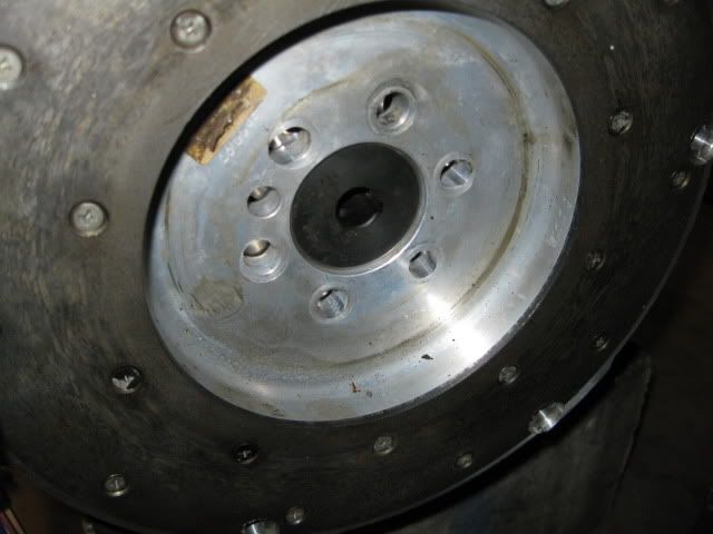
So instead of relying on this .023" of overlap, I chose to extend the crank flange surface another .273" via the pilot hole in the crankshaft. This is the same practice GM used with the 2.5's in all their various applications (GM and otherwise). The crankshafts had a removable pilot bushing that contained the flywheel flange (not the bolt pattern, just the lip for the flywheel to center upon) and depending on the application and flywheel used, these bushings changed. If it was good enough for GM, then I do not think the concept is fundamentally flawed.
Once I have everything bolted down and properly torqued, then I will take the time to dial indicate the flywheel assembly to ensure any run out is in the acceptable range. Once that passes, then I will have it checked for the proper neutral balance and balanced if needed. If I run into issue with either of these steps, then I will just send the whole flywheel package off to be remade as a single custom aluminum flywheel and eliminate the need for the flexplate and spacer entirely.
Nice shiny new parts! Even those exhaust gaskets look good.
I don't think I ever asked, but are you opening up the heads any? I know you were wanting to rev the engine pretty high, but I don't think you're changing the lifters since you want to keep the DoD, and they limit you to about 6200 RPM. But I was still wondering if you're doing any port work on the heads to let them breathe a little better.
I don't think I ever asked, but are you opening up the heads any? I know you were wanting to rev the engine pretty high, but I don't think you're changing the lifters since you want to keep the DoD, and they limit you to about 6200 RPM. But I was still wondering if you're doing any port work on the heads to let them breathe a little better.
I am planning to keep the heads stock for now. After it is up and running/tuned and dyno'd I may look into having them CNC ported and milled to bump the compression. As for the DoD lifters, I plan to see how tough/fragile they really are and plan to set my rev limiter around 6800 rpm. Once I frag one, I will probably just convert engine from DoD to VVT with some conventional lifters and play with that setup, but supposedly the VVT hardware will not clear the LS4 water pump. I think there is room to space the water pump away from the block some, but do not know how much room that setup would actually need.
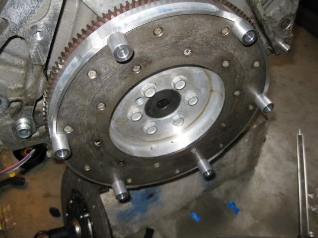
I was able to rough mockup the flywheel/clutch/pressure plate assembly today. The spacers are 1" in length and with the recesssed boss, they are .865" above the clutch face on the flywheel. Stock is .820" and I will probably be shooting for .750" once I mill them down. But they are close enough to start the mockup process:
The face of the flywheel is about 1.675" from the bellhousing face and the splines on the clutch disk start at the clutch face and protrude further into the transmission. Since the splines on the transmission start at 1.502" and go further into the transmission, the splines should extend .173" past the spline hub on the clutch disk... this leaves plenty of room for fine tuning the depth of the flywheel w/o worry of spline engagement less than 100%.
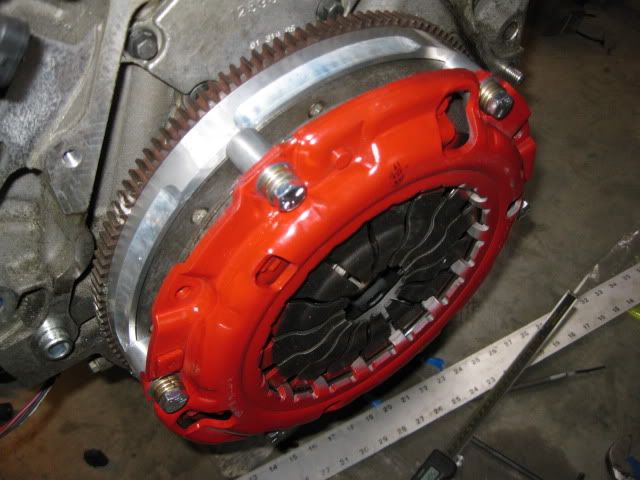
The depth of the F40 bellhousing is about 3.505" and the pressure plate is currently protruding 3.635" from the bellhousing of the engine. So, right now the flywheel/clutch/pressure plate assy is about .130" too tall to fit within the transmission. Once the spacers are milled down, I will gain .115" of clearance taking the interferance down to .015". I want to have at least .0625" (1/16") clearance between the presssure plate and the transmission case so the .200" spacer needs to be cut down another .078" to allow the pressure plate to fit... and that will be a fairly simple fix. Pulling the flywheel .078" closer to the engine will still leave the splines of the input shaft protruding .095" past the clutch hub and still retain 100% spline engagement.
The pressure plate fingers are currently protruding 3.332". Milling the spacers and making the crank spacer thinner will make them somewhere around 3.0 to 3.1". The HTOB range of motion is from 2.675" to 3.582 with the midpoint of travel being 3.129"... so everthing looks like it will work just fine.
Now I need to make the spacer thinner, mill the pressure plate spacers and put it all back together to ensure everything clears.
[This message has been edited by fieroguru (edited 03-03-2011).]
So, is it correct to think you're relying on your black-looking pilot bushing adapter thing INSTEAD of that lip you milled off?
For the most part, yes. Making the spacer thinner slides the flywheel more on the crank and less on the pilot bushing, but the vast majority of the flywheel thickness is on the pilot bushing.
[This message has been edited by fieroguru (edited 03-04-2011).]
I ran into an issue with my non-GM pressure plate today. After performing the last round of modifications to the crank and pressure plate spacers, put it all together and figured out that the pressure plate interferes with the differential protrusion into the bellhousing. I knew it was going to be close, but was hoping it would clear. This happened because the pressure plate is the elevated style vs. the flat and because it is larger in diameter for the 9 7/8" clutch... So I will need to use another clutch setup and sell off this one.
I know of another application with a 9 7/8" clutch that uses a more traditional pressure plate, but the bolt pattern isn't the 6 bolt uniform pattern (like the fiero), but instead a 6 bolt setup with every two bolts closer to each other. I can't use this one with my current flywheel since the clutch face edge was tapered by fidenza in between the 6 evenly spaced areas for the pressure plate to attach. Call me stubborn, but I refuse to use a 9 1/8" clutch anymore...
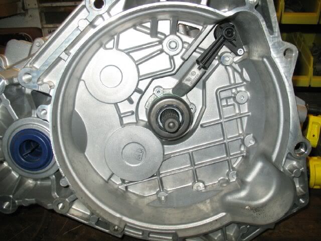
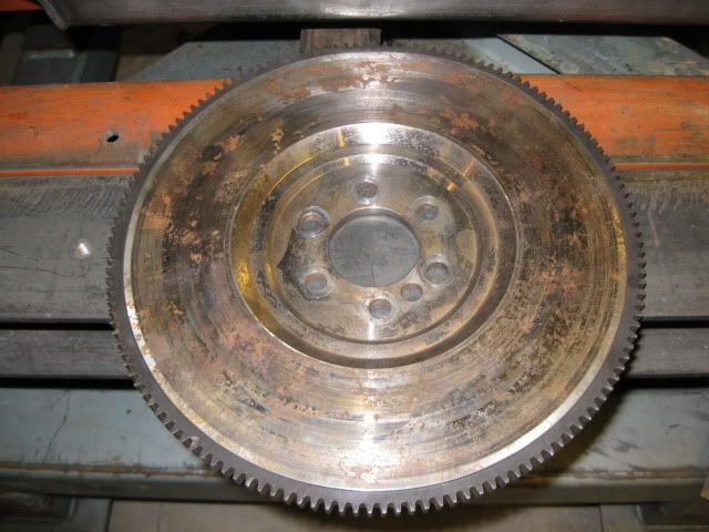
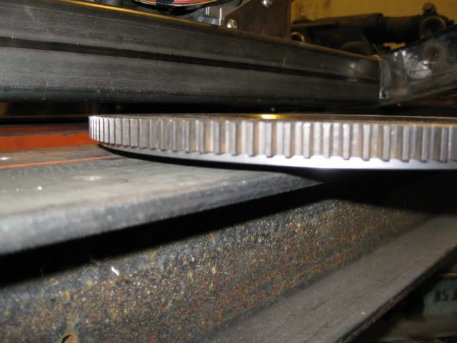
While I was at the lathe finishing up the work for the aluminum flywheel, I went ahead and turned the ring gear landing into my LS4/Getrag flywheel and installed the ring gear. The ring gear installs from the front side since it was designed around using a transmission mounted starter. The depth from the LS4 bellhousing to the clutch face on this flywheel is .83" right now before it is resurfaced. This puts the clutch/pressure plate in the stock location for 92-94 HTOB getrag. Now I need to drill the pressure plate pattern (stock fiero):
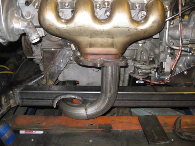
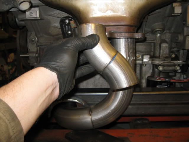
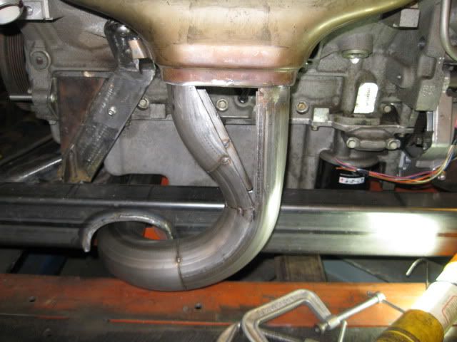
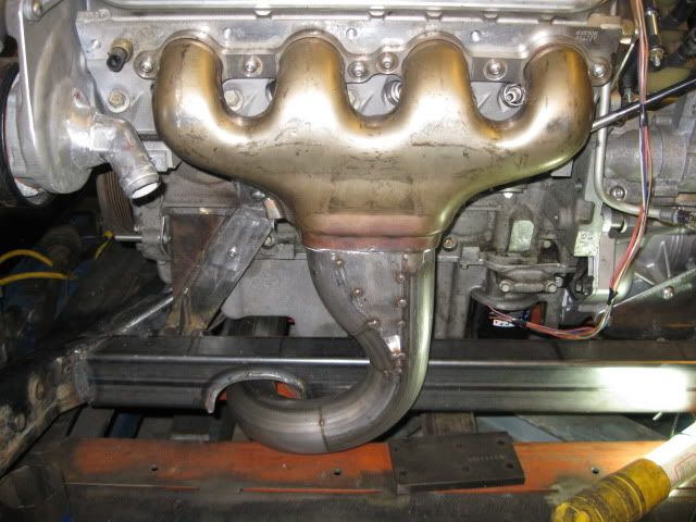
Started messing with the exhaust... I am planning on cutting off the large lower flange on the manifolds and just welding the exhaust directly to the manifold. Everything exhaust related is stainless and I have a couple of v-band clamps to allow the exhaust to be taken apart. The collector portion is going to take quite a bit of work to form the oval transition to the 2 1/2" diameter.
[This message has been edited by fieroguru (edited 03-05-2011).]
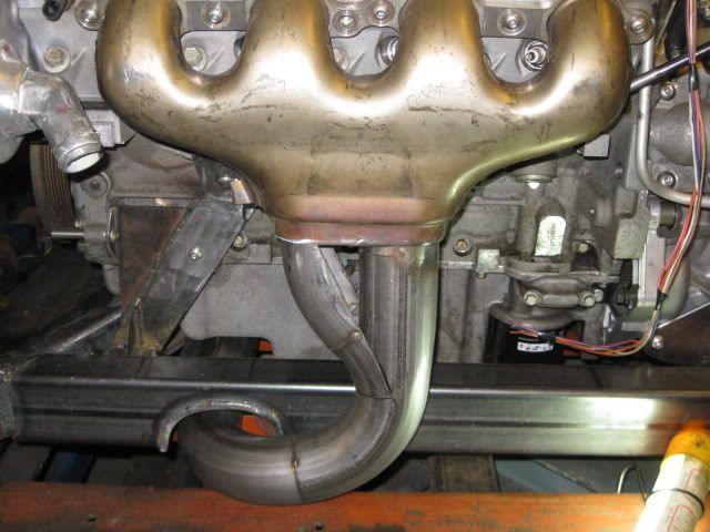
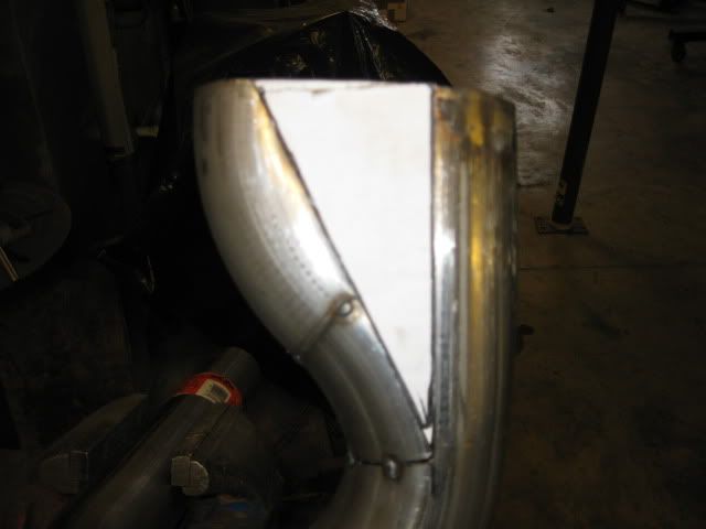
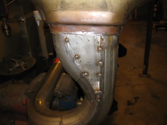
I took some of the stainless 16ga exhaust tubing, flattened it and sheared it to make the triangles and then tacked them in place:
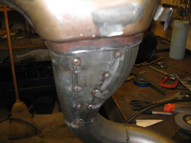
Now the front side just needs to be fully welded and smoothed:
In case you are wondering why I didn't use the factory bolt on flanges... mainly because the other half of the flanges cost $74 + the cost of the copper gaskets ($20) and the only aftermarket flanges available are mild steel. I want a 100% stainless exhaust and removing the flanges will save some weight and clean up the overall look.
Originally posted by fieroguru: In case you are wondering why I didn't use the factory bolt on flanges... mainly because the other half of the flanges cost $74 + the cost of the copper gaskets ($20) and the only aftermarket flanges available are mild steel. I want a 100% stainless exhaust and removing the flanges will save some weight and clean up the overall look.
I'm a bit surprised you didn't just make a flange for the piping side, and buy only the gaskets. But looking good. Can't wait until I'm tacking up the exhaust for mine.
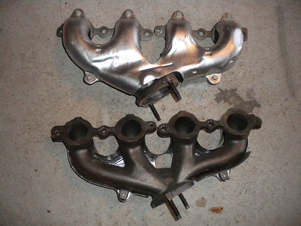
Guru, love the work and I'm sure its worth the work to say you built them from scratch, but do you think that you will gain all that much using the LS7 manis vs. stock LS3 or a set of headers like Archie makes for his swaps. When I had Archie do my install, I had him pass me a pic of the stock mani's vs his headers. I would think the header would offer a few more ponies. BUT again, I do love the work you put in on yours.
Originally posted by dobey: I'm a bit surprised you didn't just make a flange for the piping side, and buy only the gaskets. But looking good. Can't wait until I'm tacking up the exhaust for mine.
Machining stainless steel is a very slow going process, plus with a manual mill it is difficult to get precision round edges. It took a lot less time and effort to just cut the flanges off.
Guru, love the work and I'm sure its worth the work to say you built them from scratch, but do you think that you will gain all that much using the LS7 manis vs. stock LS3 or a set of headers like Archie makes for his swaps. When I had Archie do my install, I had him pass me a pic of the stock mani's vs his headers. I would think the header would offer a few more ponies. BUT again, I do love the work you put in on yours.
Rob
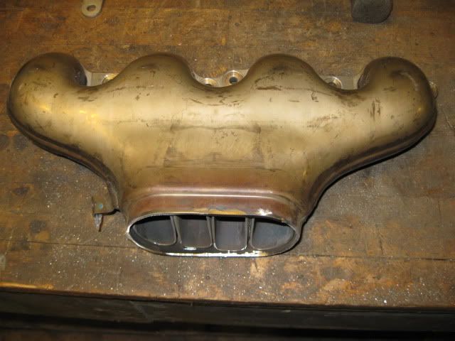
I considered alot of exhaust options before settling on the LS7 manifolds. **LS4's have a complete header/crossover/downpipe setup for the FWD croud (about $700), but I didn't know how it would clear the F40 and I know the cross over pipe would not clear the LS2 intake. **LS2/LS3 stock manifolds would also work, but I didn't like the idea of them corroding behind the heat shields, plus the heat shields are only on one side. **Early LS1 Corvette manifolds - double wall stainless for heat and noise suppession... these were strong contenders. **After market headers... I have had way too many cracked headers with the shorty style on the SBC's... didn't think much about avoiding them entirely. **Custom long tube headers using a sprint car weld up kit where all the tubes are biased to the front of the engine. Add the LS1 flange, cut to fit and I would have a 3/4 length header... these kits are not sold in stainless, but this still could be an option in the future. **LS7 factory exhaust manifolds. I am a big fan of GM's durability testing and prefer to use as many GM designed parts as possible. The LS7 manifolds are also quite compact and easily fit the fiero engine bay. The LS7 manifolds are actually hydroformed tubular stainless steel headers and fully incased in another section of stainless steel for noise and heat suppession. They work very, very well and have proven to be worth 10-25 hp compared to LS2 or LS3 manifolds. Long tube headers can out perform them, but I doubt any short runner header will. So for around $100 the LS7 manifolds provide a very durable solution that pasted GM duability tests to perform leak/crack free under 500hp conditions, they are stainless steel so they will retain their good looks, they will put minimal noise/heat put into the engine bay, they are lighter than the LS4 manifolds (before I cut the flange off), and they have been proven to work well... My question is why isn't everyone using them?
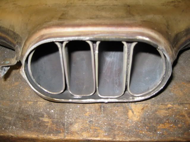
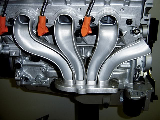
Here is a cut away pic to show you what the insides look like:
Now the LS7 manifolds are probably a little big for the a stock 5.3L, but I may choose to upgrade some cubes in the future. For reference the tube cross-sectional area at the port is about 2.37in-sq and 2.12in-sq at the collector with the primaries being about 8" in length on the inboard cylinders and about 10" on the outer ones. The DT headers are 2.40in-sq for their length, but do have primaries that are 1 1/2 to 2x as long.
[This message has been edited by fieroguru (edited 03-07-2011).]
I'm sure you've worked out how you're going to R&R this system once this is all welded together & in the car with all the other stuff like sway bars, A/C compressor & Intermediate shaft etc.
I can tell you for sure, It's not real easy to remove either header by it'self. Getting it thru around or over all the other stuff can be done but it would take time. I think it could be a real PITA to remove the LS7 manifold when it's permanently attached to the down pipes.
Archie
Agreed.
I am planning the v-band clamp for the front manifold to be between the oil pan and the front crossmember. The rear manifold will also have one before it merges with the front pipe before the muffler. The rest of the exhaust will then be welded solid very similar to my last SBC setup.
Simple. They suck. Look how they dump. Look at the oval outlet. They're not even iron. And yours are writing checks that your LS4 can't cash. No sleeper-ness to them. No stealth value. I've already shown that the '00-'02 F-car LS1 manifolds are a truly excellent fit. N/A, they're proven to be only 12 HP less than 1.75" long-tubes on a 400 RWHP build. Less than 12 on a 600 RWHP turbo build. They're durable, nicely styled, cheap, easy to get, and they offer heat shields on both. They can be extrude honed. Edelbrock makes tubular versions, albeit way overpriced. What's not to love?
Originally posted by KissMySSFiero: what do you plan on doing for the axles?
I will probably just use the hybrid tripods & Corsica/Fiero axles I made for my 4.3/F40 swap to start with. Long term I want larger wheel bearings and associated CV splines, and will probably just get some custom axles made.
quote
Originally posted by KissMySSFiero: Wasn't there a grand prix that used a 9 3/4" clutch? Maybe the turbo/282 combo, one from the early 90's.
Yes. But the 282 combos had a 14T x 1 spline vs. the 23T x 1" I need for the F40. The 284/3.4 TDC was a 9 3/4 23T x 1" setup, but used a pull style pressure plate. combo . I will most likely have a custom clutch made that has an OD of 10" and an ID of 6". This will maximize the clutch area on my friction surface and help improve drivability. I have already found several clutch disks that would work, but still trying to decide on the pressure plate
quote
Originally posted by KissMySSFiero: Have you finished the getrag/ls4 flywheel?
Almost, Just needs the fiero pressure plate pattern drilled/tapped. Then I need to make the starter plate for the 92-94 HTOB getrag.
quote
Originally posted by KissMySSFiero: Any other progress?
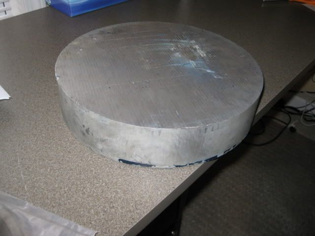
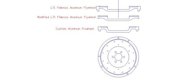
Not much... I ordered and now have a 12" x 2 1/8" 6061 aluminum disk to make a custom flywheel and the 10" OD/6" ID fidenza friction surface. Still working on the final flywheel design and have everything but the final thickness and the pressure plate pattern done... which I can't do until I settle on a pressure plate. Then I will go to a machine shop friend of mine with a large enough lathe to chuck up and turn my new flywheel.
I spent last weekend working on the wifes maxima and traveling out of state... but Sara and the girls are going to Chicago for about 10 days in a couple of weeks, and I plan to hit this swap pretty hard during that time.
Simple. They suck. Look how they dump. Look at the oval outlet. They're not even iron. And yours are writing checks that your LS4 can't cash. No sleeper-ness to them. No stealth value. I've already shown that the '00-'02 F-car LS1 manifolds are a truly excellent fit. N/A, they're proven to be only 12 HP less than 1.75" long-tubes on a 400 RWHP build. Less than 12 on a 600 RWHP turbo build. They're durable, nicely styled, cheap, easy to get, and they offer heat shields on both. They can be extrude honed. Edelbrock makes tubular versions, albeit way overpriced. What's not to love?
Blah, Blah, Blah... Were you trying to say something?
Hey guru, I was just wondering what you were planning to do for the shifter. Are you going to use a modified 4 speed shifter? I was thinking of making a custom shifter assembly, built like the current era shifters in the GM FWD lineup.
Simple. They suck. Look how they dump. Look at the oval outlet. They're not even iron. And yours are writing checks that your LS4 can't cash. No sleeper-ness to them. No stealth value. I've already shown that the '00-'02 F-car LS1 manifolds are a truly excellent fit. N/A, they're proven to be only 12 HP less than 1.75" long-tubes on a 400 RWHP build. Less than 12 on a 600 RWHP turbo build. They're durable, nicely styled, cheap, easy to get, and they offer heat shields on both. They can be extrude honed. Edelbrock makes tubular versions, albeit way overpriced. What's not to love?
You would rather have iron over stainless? wow I think guru made a good choice here the ls7 manifold is more of a header than a manifold bang for the buck I don't think you can beat them for the $100 he paid. With the way he is fabing the dumps thats going to look way cool. You would be suprised at what checks LS4's can cash with a little work.
Simple. They suck. Look how they dump. Look at the oval outlet. They're not even iron. And yours are writing checks that your LS4 can't cash. No sleeper-ness to them. No stealth value.
What do you base this on? They're lighter, They're Stainless and NOT cast iron, NO v8 fiero is a sleeper, and even if they do cost a little low end punch, who cares. It's not like ANY v8 fiero ever had any trouble getting off the line. So they may be too big for a basically stock LS4, but had you read his thread completely, you would know he's planning future power upgrades for the engine. Going this route eliminates his need to design and build a second exhaust system
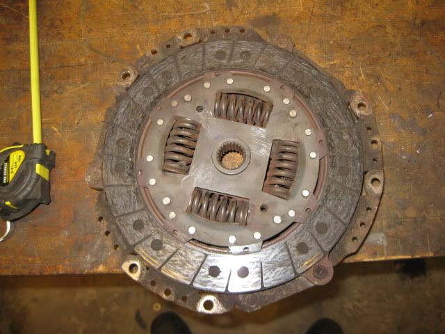
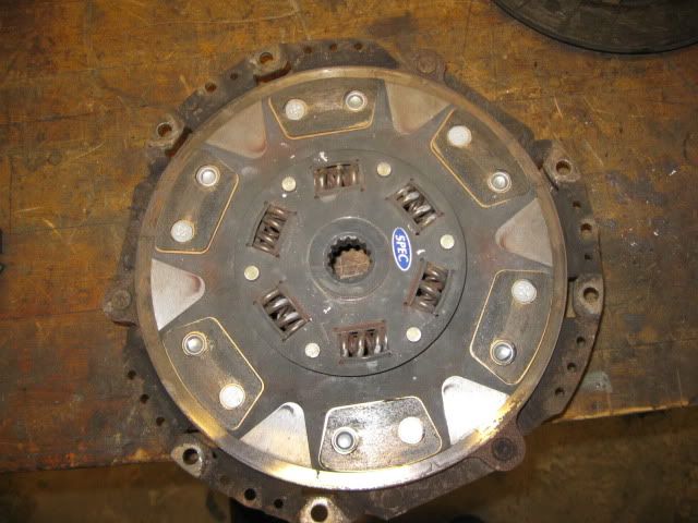
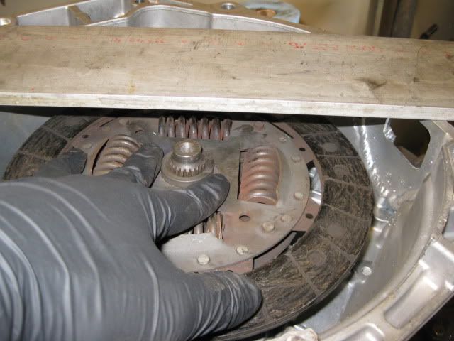
I was able to stop by the junk yard and get a used clutch from the application I think will result in the largest possible clutch. The transmission was already pulled, so 6 bolts and it was mine (plus $30). The pressure plate surface is about 9 7/8"
Here is a stock Fiero 9 1/8" clutch for a visual reference:
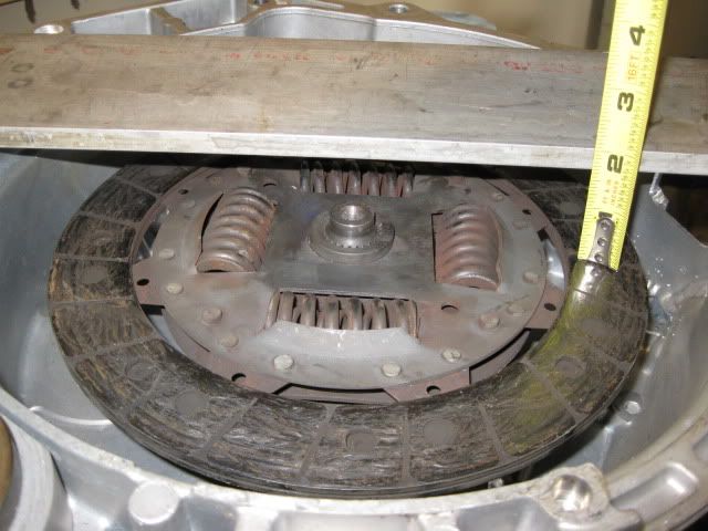
It was much easier to pull the F40 off the 4.3 setup (no mounts on the tranny), so I used it to take some rough measurements:
With the clutch disk on the input shaft, the flywheel face can be between 1 5/8" and 1 7/8" deep into the bell housing and retain 100% spline hub engagement as well as not make contact with the HTOB sleeve.
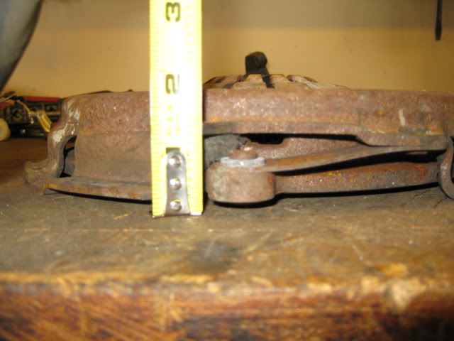
The pressure plate has a protruding lip by the torque bands and it is 1 1/4" from the flywheel face. This part could make contact with the differential bulge deep in the bell housing. The differential bulge at the OD of the pressure plate is about 3" to 3 1/16" deep into the bell housing.
So with the flywheel at 1 5/8" thick, and the pressure plate lip another 1 1/4" into the bell housing (2 7/8") there should be ample clearance to the differential bulge at 3". A flywheel thickness at 1 3/4" would place the place the pressure plate notch at 3.0". The clutch fingers on this clutch (with some washers on the disk to account for some wear) are at 1.75" from the flywheel surface (same as the overall depth of the pressure plate). With a 1 5/8" flywheel, the clutch fingers would be at 3.37" which is within the HTOB range of motion from 2.675" to 3.582 with the midpoint of travel being 3.129". This should give the clutch release fingers about .20” of movement to the rear as the clutch wears and about .7” of clutch release travel w/o the HTOB over extending.
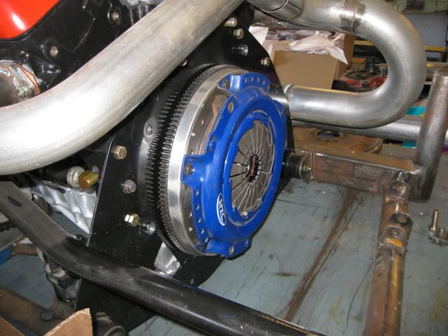
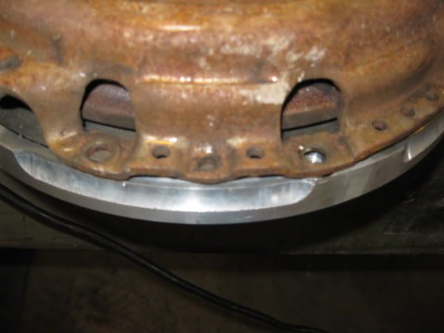
This was the first clutch setup I looked into, but it will not work with my fidenza flywheel due to the pressure plate bolt pattern on the pressure plate and the machined edges of the flywheel. In this picture, one of the pressure plate bolt holes lands on the full size portion of the flywheel edge, but the other one is in the clearanced portion. So I had initially discarded this flywheel setup.
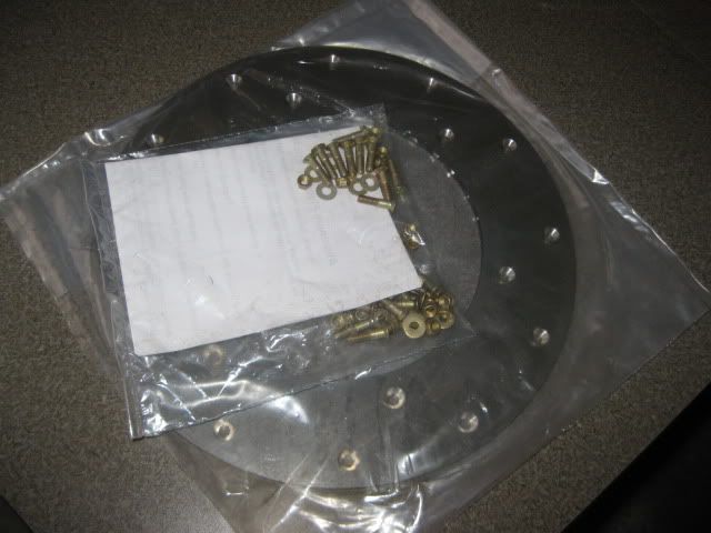
So I have decided to just make a new flywheel and ditch the flex plate/spacer/flywheel setup I currently have. These parts have already been purchased for the new flywheel:
I was able to stop by the junk yard and get a used clutch from the application I think will result in the largest possible clutch. The transmission was already pulled, so 6 bolts and it was mine (plus $30). The pressure plate surface is about 9 7/8"
What is the application? While the large diameter will help, it certainly doesn't have a lot of friction material. Compare it to the Fiero Store Ram clutch. (It's advertised as 9 3/4 but is really 9 5/8.) It seems to have a lot more friction material. I'll get you a pic of the face of the pressure plate if you want.
I know that you may want something more substantial than this, but I chose it solely because of it's larger friction surface. I understand the clamping load is a bit higher too. I wasn't happy with my Spec 2. Figure I'd go with something larger but less exotic.
[This message has been edited by Raydar (edited 03-19-2011).]
What is the application? While the large diameter will help, it certainly doesn't have a lot of friction material. Compare it to the Fiero Store Ram clutch. (It's advertised as 9 3/4 but is really 9 5/8.) It seems to have a lot more friction material.
I know that you may want something more substantial than this, but I chose it solely because of it's larger friction surface. I understand the clamping load is a bit higher too. I wasn't happy with my Spec 2. Figure I'd go with something larger but less exotic.
I am not sharing the application for this clutch just yet, but it is a non-GM application. It is a stock application and Spec offers a Stage 3+ version for it off the shelf. Now that I know it will fit, I want to give them a call and see what the stage 3+ version is rated for (needs to be 450 lb-ft +) and if it can be had with a spring less hub.
It would be nice for the clutch material to be wider, but it can't be w/o changing to a completely different clutch setup and the available applications with 23x1 spline and 9 7/8" diameter are very, very few. Some are ruled out due to the raised pressure plate, some because the bolt pattern for the pressure plate will not fit within the material available on the flywheel, some for price or pressure plate design (porsche).
An industrious person could mix/match the previous clutch disk I was using with a non-raised pressure plate of the needed size, but I am looking for a stock clutch/pressure plate combo that already has some upgraded versions available. I wanted to go the largest diameter possible... plus I normally take the hard way...
In the last month I have learned way more than I ever wanted to know about the various clutch/pressure plate combinations across the imports and domestic applications.
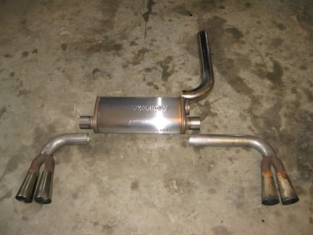
I pulled the Blue 88 in and slid the engine/tranny/cradle under it to start mocking up and locating the remaining portion of the exhaust. Here are the parts for the rear most portion of the exhaust:
Yes, I know the stock fiero tips are not stainless steel and probably a restriction... but I use them on all my personal swaps, so they are staying. Once the muffler location is locked down, then the 3" inlet will be tapered to meet up with the 2 1/2" from the front. The rear manifold section will be last and the most complicated as it must taper from the LS7 manifold and then merge into the 3" section of pipe before the muffler... lots of cutting/fitting.
Originally posted by fieroguru: I am not sharing the application for this clutch just yet, but it is a non-GM application. It is a stock application and Spec offers a Stage 3+ version for it off the shelf. <snip>
Nice work just wondering why not just get a triple disc or dual disc clutch then there is no need for a flywheel just a flex plate will do
I plan for this swap to be my daily driver in the summer, so it must have docile street manners... you do not get that with a dual or triple disk clutch (plus a double or triple clutch will set you back $750 to $1500 vs. about $450). But for those who wanted to go that route, the 2300 ford's used in many racing applications came with the 23 x 1 spline and there are double and triple disk racing clutches available for them.
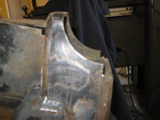
Today was a good day for destruction... The test fit into the blue car showed a couple of areas that needed some additional clearancing.
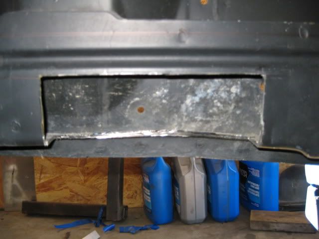
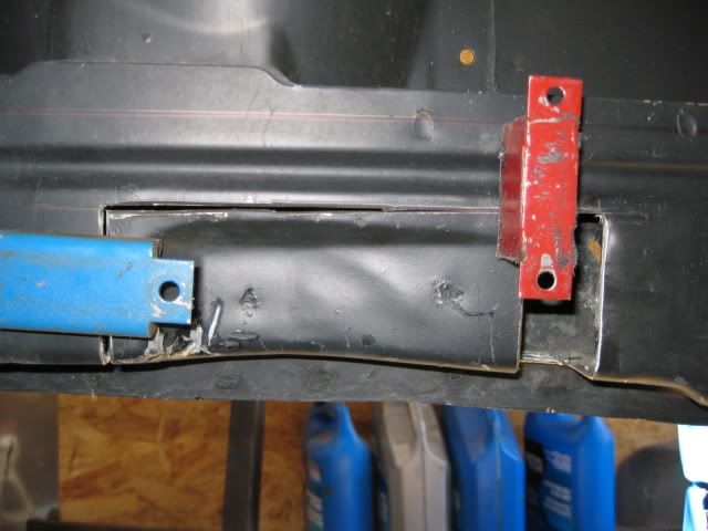
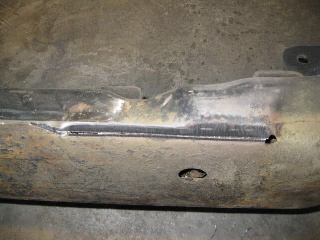
As discusses a page or two ago, the factory frame notch on the driver's side was moved back 1" so it would better clear the F40:
I will leave it just tacked in place while the engine/tranny/cradle are test fitted again to verify 1" was the proper amount to move it.
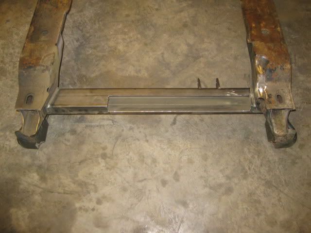
Next the cradle needed some slight tweaks. The Magnaflow muffler is thicker than the Flowtech Afterburner I usually use, so I needed to clearance the rear cross-member slightly so I could raise it up more.
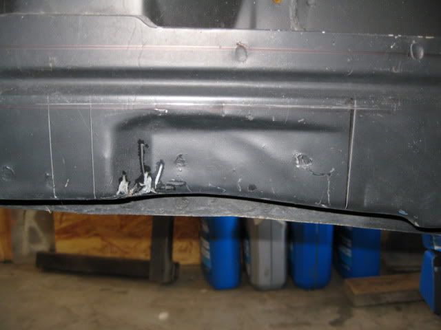
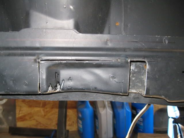
In addition to the rear cross-member, the factory exhaust notches in the cradle needed to be modified slightly. They were shortened about 3/8" and reshaped to better clear my exhaust pipes. This modification allows the Magnaflow muffler to fit without any modifications to the stock trunk. In this pic the bottom portion has already been cut back and the marker outline shows the amount to be removed:
The last modification was to the lower lip of the passenger cradle rail. The 2 1/2" exhaust runs within 3/8" of it and it needs more room for the enlargement to 3". I had kicked around trimming it for the entire length, but chose to just do the portion that is behind the oil pan.
After the next exhaust mockup all the cuts made today will be welded up and ground down smooth.
I'm sure you're aware, but for others that may not be, that cradle lip is just a weld-flange for easier automated spot-welding on the assembly line. You could've removed it entirely without any concerns.
Originally posted by Isolde: Why? I've seen some engine dyno sheets for some built N/A 5.3s, none even reached 440 ft-lbs. You secretly boring yours to 5.7L?
Read the thread. He's said multiple times he will likely add N20 or turbo later on.
440 ft-lb might seem like a lot for a 5.3, but the main thing holding that back is the DoD. It's a lot easier to get up to 450 ft-lb with a stronger valvetrain that can take you up to 7000+ rpm.
It will be a Spec Stage 4+ (solid hub and solid ring of friction material) of the version I just test fitted. The list price is over $600, but it includes a HTOB that I will not need, so maybe I can get the cost down some.
Yes the clutch is alittle overkill at the moment, but wanted to make sure it would hold any future upgrades (NOS, Turbo, stroker kit, or a 6.0, 6.2).
Ooooooo... I hope for you it's streetable. That's a lot of cashoolah if it turns out to be chattery at anything but higher rev clutch dumps. What's SPEC say about the holding power of it?


.jpg)


 Your craftsmanship is stunning. Your ideas original. And your build is just amazing.
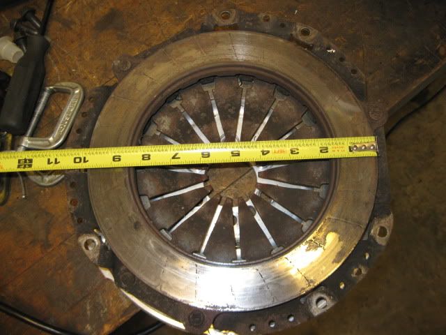

.JPG)
.JPG)


 Ooooooo... I hope for you it's streetable. That's a lot of cashoolah if it turns out to be chattery at anything but higher rev clutch dumps. What's SPEC say about the holding power of it?