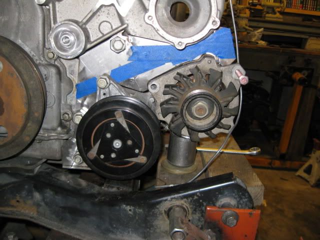
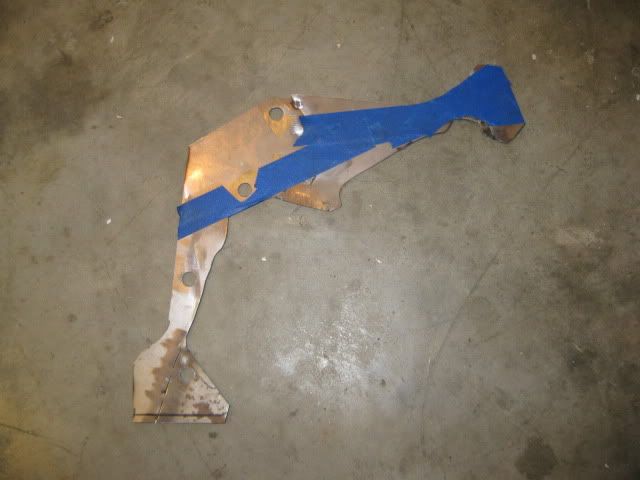
Mocked up the LS4 compressor and Fiero alternator and made a template for the bracket. It is made of several pieces of 16ga sheet metal. The sheet metal is quick to shear and shape and allows me to fit the contours of the accessories one section at a time. Then tack weld them together as you build the final bracket shape. Once the template is done, then tape can be used to smooth out some of the sections as well.
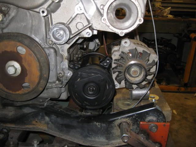
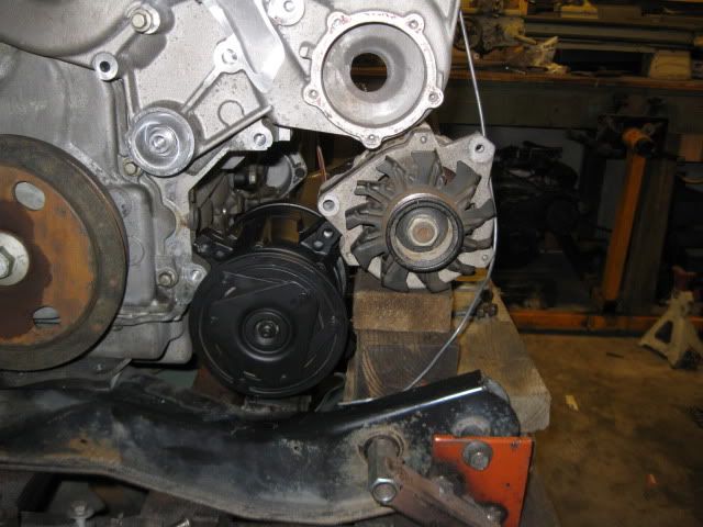
I wasn't completely satisfied with this bracket... concerned with the amount of material (or lack there of) between the AC compressor / engine and between the alternator / water pump. For grins I mocked it up with the 88 4cyl a/c compressor:
If I use the 88 4 cyl AC compressor, the bolt boss right next to the alternator would need to be cut off... The other downside of the fiero AC compressor is the smaller pulley. It was designed for an engine with a much smaller crank pulley (about 6") and the LS4's crank pulley is HUGE. Using the fiero AC compressor would speed it up considerably vs. the LS4 compressor... Going to spend a few more days doing some more checking other alternator alternatives (like the one from my 97 truck).
Spent the rest of the day gathering some weight measurements to keep track of the +/- of the various component weights. Ideally, I would like to end up with a lighter combination than the stock LS4 setup and a relatively light overall drive train. Here is a rough run down so far..
There are still alot of things left unaccounted for like the material removed from the valve covers and water pump, axle differences, stock vs. my custom mounts... largely because I either didn't weigh the stock parts before modifying them or I never had them to start with (like axles/mounts).
When I pull the 2.8/Getrag from the Formula, I plan to take the whole drivetrain as it is dropped from the fiero into work to wieght it on one of our pallet scales. This will include the cradle, engine/tranny/mounts/brackets/accessories, harness, ecm, axles, suspension/brakes and exhaust. Then I plan to do the same to the LS4/F40 in the same configuration to see how much total weight I will add to the backend vs. stock. This will also account for the weight increase for the 12" brakes and possible weight reductions in coil overs.
[This message has been edited by fieroguru (edited 12-19-2010).]
Fieroguru, You have a great build going there. And it is really timely, as I have an LS4 and F40 in my garage waiting to be installed. With your accessories setup, were you planning to put an idler pulley between the alternator, and the AC compressor, to get enough rap around the compressor pulley? Where in your belt system, were you going to put a tensioner, or was the alternator going to be pivot mounted. Cheers, Mike
Fieroguru, You have a great build going there. And it is really timely, as I have an LS4 and F40 in my garage waiting to be installed. With your accessories setup, were you planning to put an idler pulley between the alternator, and the AC compressor, to get enough rap around the compressor pulley? Where in your belt system, were you going to put a tensioner, or was the alternator going to be pivot mounted. Cheers, Mike
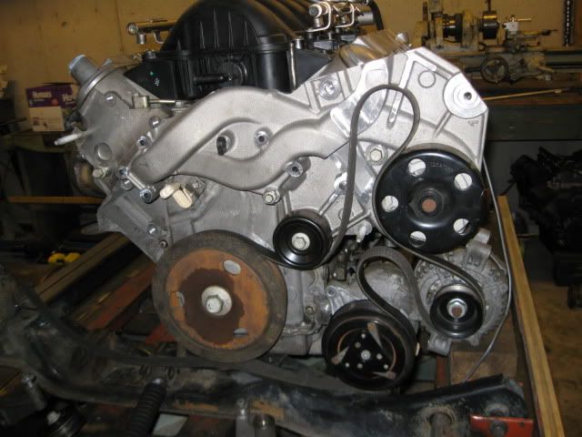
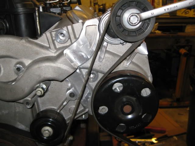
This picture shows the approximate locations for idlers (loops in the belt):
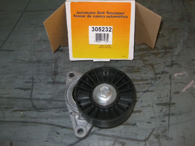
I am still researching tensioner options and will most likely put the tensioner up top over the water pump. I could cut the upper aluminum webbing and install this compact tensioner for $35.99 (part # 305232).
The alternator will be solid mounted, but if I wanted a manual belt adjustement, I would use the mercedes offset idlers (cam operated to tighten/loosen the belt).
[This message has been edited by fieroguru (edited 12-20-2010).]
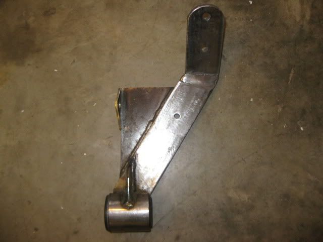
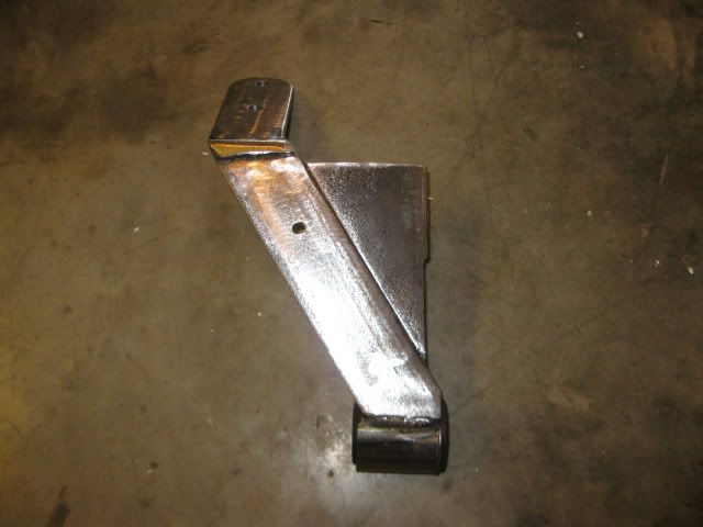
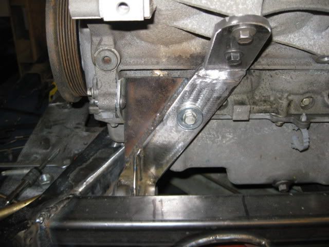
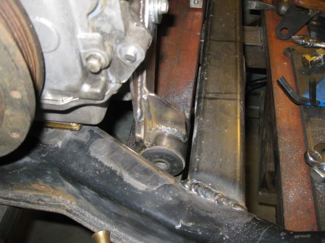
As I continue to ponder the accessory drive and wait for a 2000 chevy truck alternator to arrive, decided to finish up the front engine mount and keep it seperate from the accessory drive bracket. There isn't much room between the block and AC compressor, but some 3/8" x 2" steel bar will fit and be plenty stiff. I was able to use 4 bolts on this mount as well to help spread the load. I also made another bushing locator so this bushing is co-linear with the front transmission bushing.
[This message has been edited by fieroguru (edited 12-23-2010).]
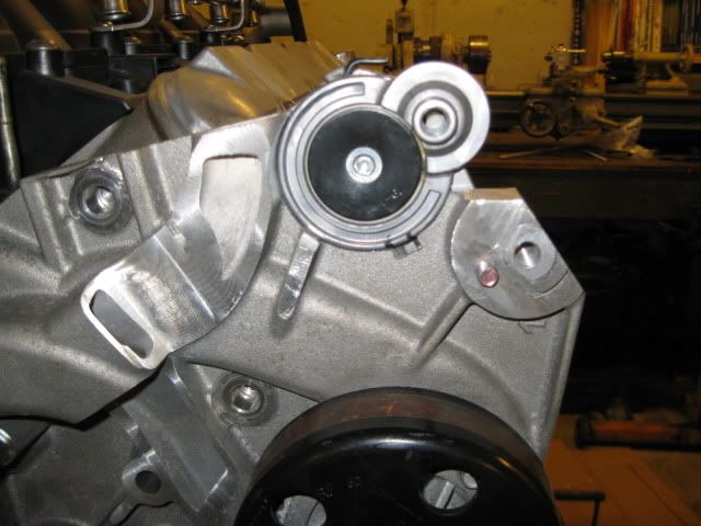
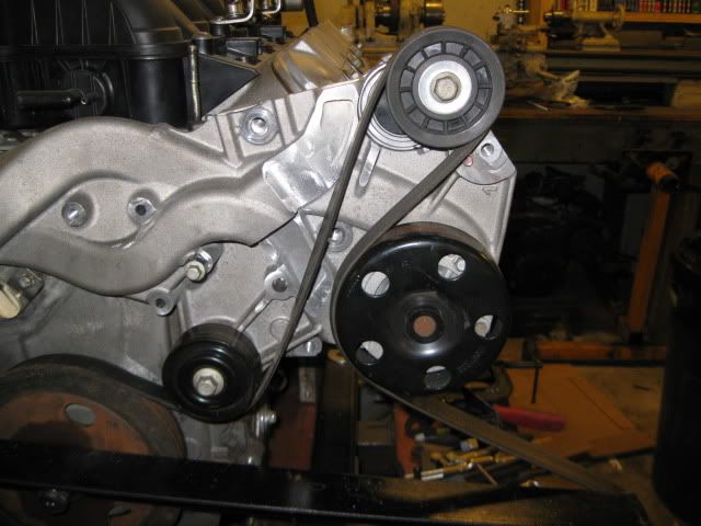
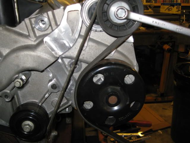
More LS4 water pump butchery today... but now I have a belt tensioner and upper idler pulley:
This location places the tensioner on the slack side of the belt and places both bolts in an area of the water pump casting that is quite thick. This will provides ample material for threads as well as milling about 1/8” off the back side to level out the area where the tensioner mounts (and give the front bolt clearance to the valve cover). I still need to make a spacer for the idler to position it in line with the balancer and might relocated the bottom idler by the balancer up about 1/2" to give more room between the two belts.
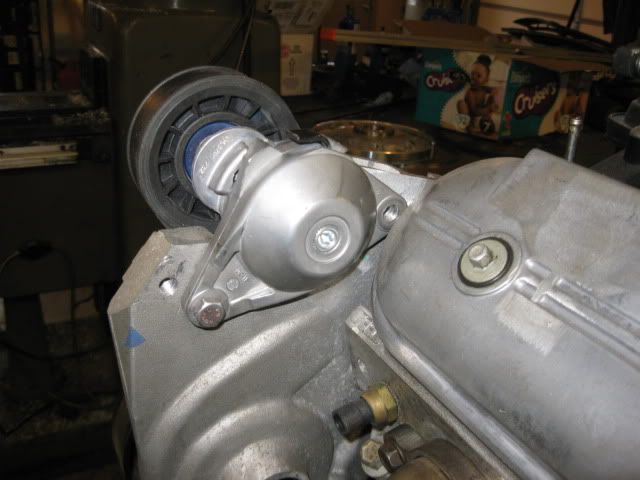
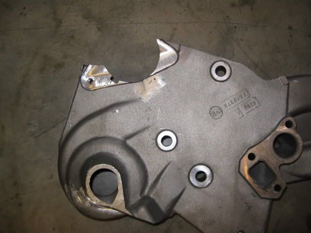
During "quiet time" I was able to fire up the mill and clearance the water pump housing for the tensioner:
There should be enough room for the stainless steel button head now.
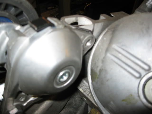
The belts do not really get much closer as the tensioner moves:
I still need to do some more clearancing to the boss on the water pump so the tensioner has full range of motion. Right now it takes up about 1" of belt slack and I would like to to be closer to 2".
Maybe on Sunday I will switch the welder over to aluminum and do some welding on the water pump.
I'm paying close attention to this as i have an Ls1 and want to mate it with an F40. Will the F40 bold up to the Ls1 or just the Ls7?
The LS4 is the only LS based engine with the FWD Metric pattern and is the only LS based engine that will bolt directly to the typical fiero transmissions including the F40. The LS1, LS2, LS3, LS6, LS7 and LS9 will all require an adapter plate.
Originally posted by fieroguru: The LS4 is the only LS based engine with the FWD Metric pattern and is the only LS based engine that will bolt directly to the typical fiero transmissions including the F40. The LS1, LS2, LS3, LS6, LS7 and LS9 will all require an adapter plate.
Don't forget the LSX and LSA.
But to be more specific, the LS4 block is the only small block V8 from GM to ever be in a FWD vehicle, and the only one that will mount to the FWD Metric pattern directly. And it's not very likely that GM will produce a new small block V8 like that anytime soon. If you want a V8 that bolts straight up to the GM FWD Metric transaxles, your only choices are LS4 or Northstar. And both will require some small modifications to any manual trans.
Just thought I'd post in case anyone wanted to come ask about any other V8 possibilities for a direct bolt up.
It gets alittle confusing when you specify FWD, since there were longitudinal FWD applications that used V8 engines (both big and small block configurations) but all had the BOP pattern, not the Metric pattern.
The LS4, N* (and its sister the Aurora 4.0), and the 4.1/4.5/4.9 pushrod caddilac V8s are the only V8 engines that use the Metric pattern. All other V8's will require an adapter plate of some sort.
Originally posted by fieroguru: ... The LS4, N* (and its sister the Aurora 4.0), and the 4.1/4.5/4.9 pushrod caddilac V8s are the only V8 engines that use the Metric pattern. All other V8's will require an adapter plate of some sort.
The LS4 is the only LS based engine with the FWD Metric pattern and is the only LS based engine that will bolt directly to the typical fiero transmissions including the F40. The LS1, LS2, LS3, LS6, LS7 and LS9 will all require an adapter plate.
I have a nice LS1 out of a 99 corvette. Was hoping for an Archie kit for an install next year. But you mention "FWD Metric pattern" ..doest the mean that the rotation of the engine is so that in FWD position, it can be moved to the rear of the Fiero? Does the Corvette C5 Ls1 rotate in a direction so that it cannot be moved to the back of a Fiero and be used with an F40 or Getrag?
I was also told that i can flip the intake so on that LS1 engine as well, is that true?
Just an inquire here, regarding the water pump. Wouldn't be easier to switch the setup over and use the RWD water pump design? Instead of going though all of the work cutting up the casting, you have. It would put the pump back above the crank pulley and help clean up the engine some. Always like the work you do. First class all the way.
[This message has been edited by RumbleB (edited 12-30-2010).]
Just an inquire here, regarding the water pump. Wouldn't be easier to switch the setup over and use the RWD water pump design? Instead of going though all of the work cutting up the casting, you have. It would put the pump back above the crank pulley and help clean up the engine some. Always like the work you do. First class all the way.
Only way you can use the RWD water pump is to cut the majority of the passenger side frame rail for clearance... there just isn't enough room for it to fit, then you have the issue with the outlet and heater hoses exiting to the rear of the chassis and looping back up front. If you look at the belt location vs. the timing cover on the LS4, there is only about 1/2" between the two. Then look at the RWD pump and see home much space there is between the backside of the pump and the pulley... probably 1" to 1 1/2", and then the pulley itself sticks out another 3-4 inches from there. If you look at some of the clearance shots between the balancer and passenser frame rail, the needed room just isn't there.
The "easy" solutions are either to run the same electric water pump setup like Archie does on all his swaps, get the WCF alternator bracket and mount it up top, or notch the passenger frame and mount is down low like FieroAddiction and Sinister Performance.
One of my many character flaws is I like to do things the hard way and come up with thought provoking solutions. The more effort involved, the greater the chance of my swap remaining unique...
I am hoping to have a couple pics of some welded alumimum this evening to get this thread back on track.
[This message has been edited by fieroguru (edited 12-30-2010).]
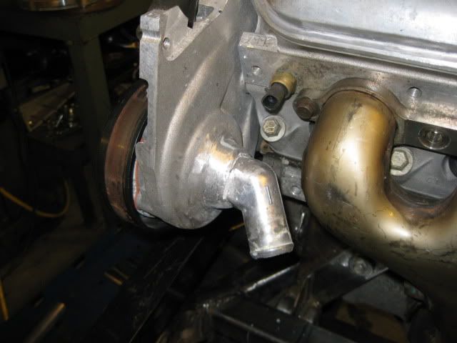
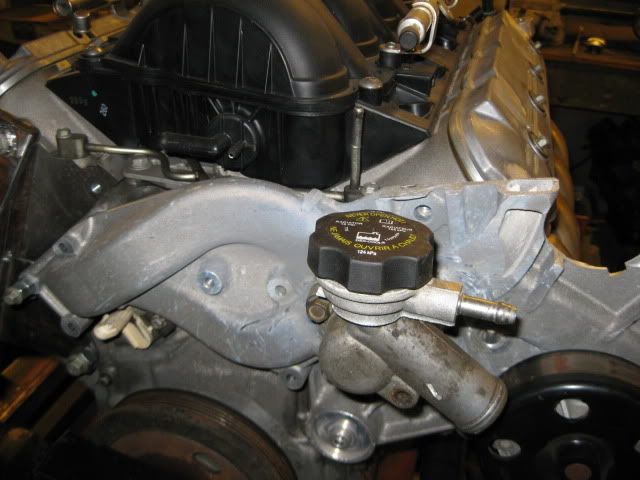
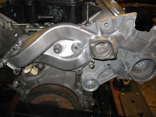
The nipple for the water pump inlet was welded in place and the welds cleaned up:
The thermostat flange was also welded on. Here is the other half that will bolt in place:
I still need to weld the top of the coolant fill to the bolt on part. I purchased a 12" piece of aluminum pipe so I can adjust the elevation of the cap slightly.
Well my alternator package showed up yesterday and had a distributor inside... going to be another week or two till I can get back to the accessory bracket.
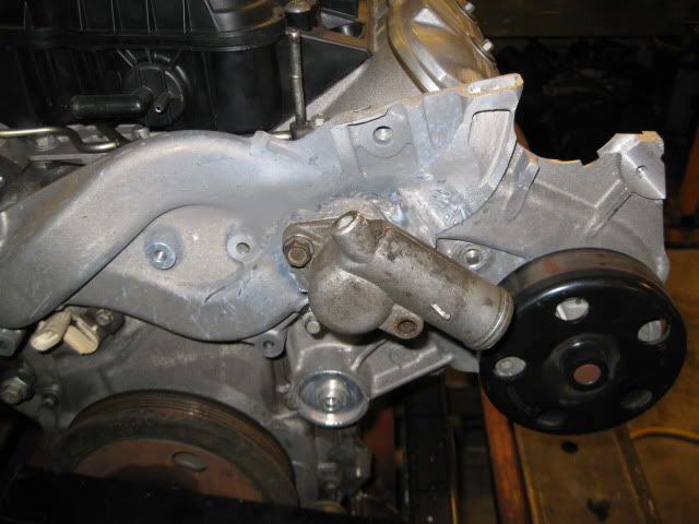
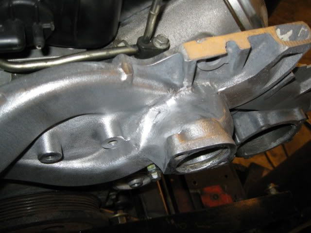
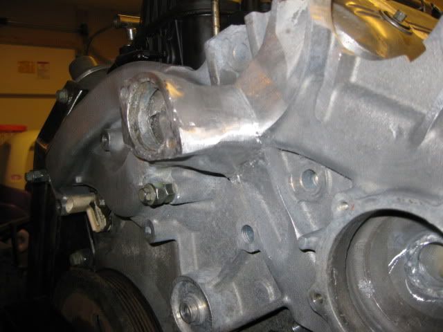
So I spent a little time today capping the open passages on the water pump and cleaning up and smoothing all the welds.
On Sunday I should be able to finish the water pump housing... just need to build up the upper tensioner bolt area, cut out the thermostat area, then smooth out all the edges in the places it was cut. I have already done the first series of leak tests and everything checks out. Eventually, I will cap everything and pressurize it to 30 psi and check for air leaks.
Once it is leak free, then it will be ready for some sand blasting to give the whole thing a uniform texture.
[This message has been edited by fieroguru (edited 01-01-2011).]
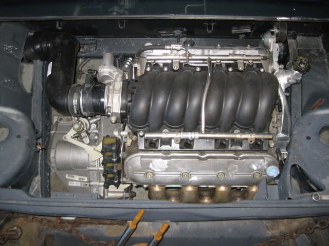
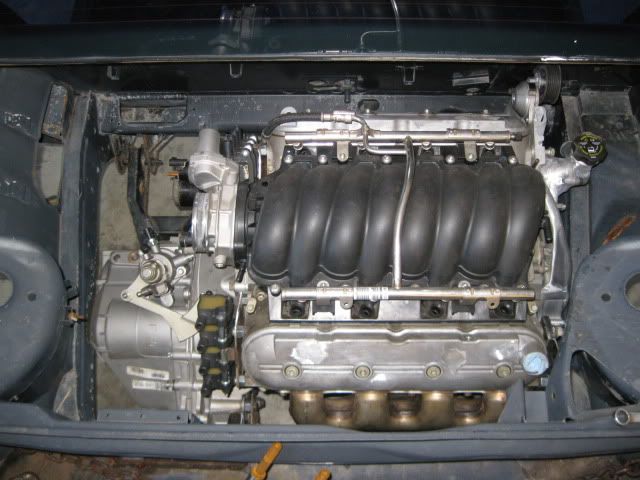
Well my daily driver truck started to act up and wouldn't start, so I spent the better part of my New Years holiday working on it. Once it was running again, I was in the mood for some inspirational pics and needed to finalize the engine placement anyway... so back in the mockup chassis the engine/tranny/cradle went:
I went ahead and taped the 85mm MAF on the end of the throttle body and mocked up the air intake tube. This is the same GM plastic tube Darth Fiero uses on his 3800SC swaps. It need to be sectioned in the center to shorten it and then I can use some of the material to space the MAF from the throttle body and get the front/back portion of the intake tube to be closer to the driver side frame rail. If I can not get this plastic tube to work, I will just get some 3 1/2" mandrel bends and weld something together.
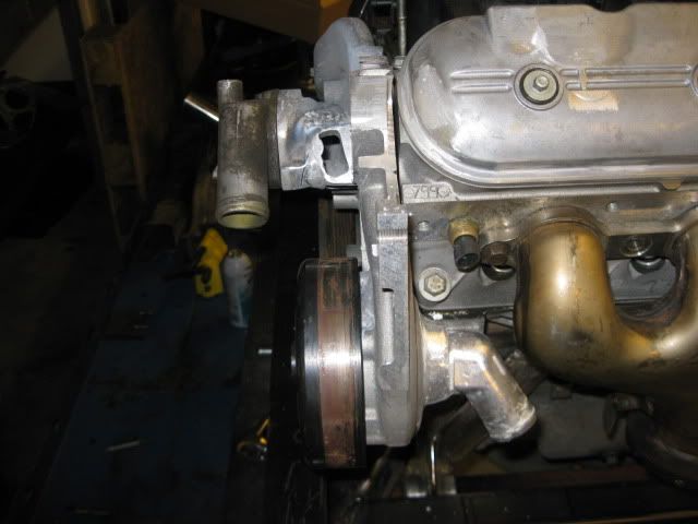
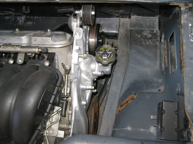
Here is the new thermostat housing and coolant fill location. The hose from this will easily clear the belt and the passenger frame rail.
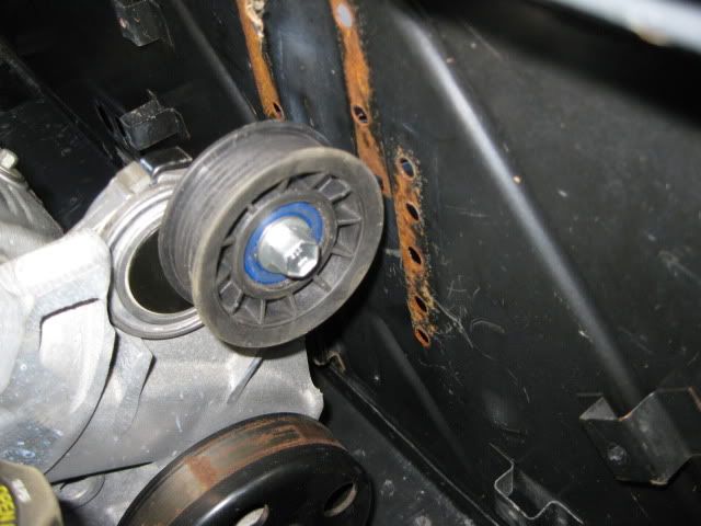
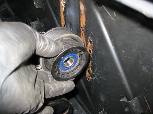
The tensioner pulley is about 5/8" from the firewall and only gets about 1/8" closer when the tensioner is pulled down. The vast majority of the engine movement will be to the rear, so this should be plenty of clearance. I could always swap out the pulley on the tensioner for the stock LS4 tensioner pulley that is about 1/2" smaller in diameter to gain some more clearance. Also, it is clear than the tensioner pulley will be into the passenger hinge box... it is good than my fiero will not need/have these boxes... mostly in an efffort to remove clutter from the engine bay.
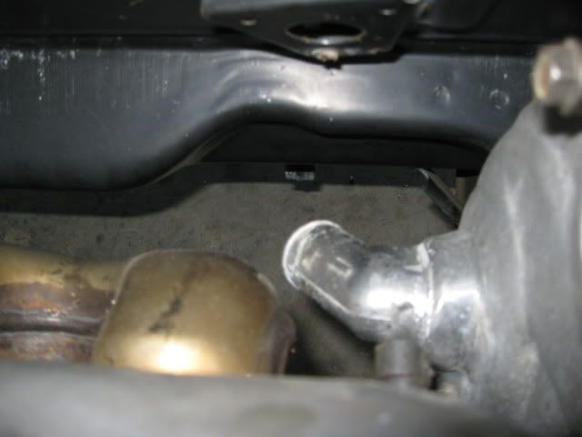
The coolant inlet on the back side of the water pump will clear everything and have the hose routed down by the recessed portion of the double firewall panel:
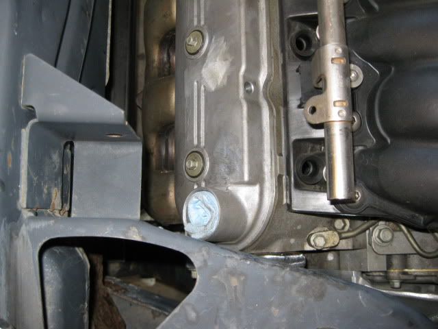
Water pump cleatance to the passenger frame rail... lots of room here:
Oil fill is still trying to co-exist with the dogbone bracket. My fiero will not have this dogbone bracket to contend with.
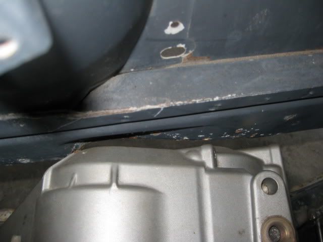
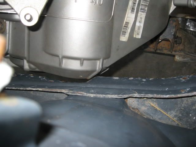
F40 transmission to the driver side frame rail has about 1/4" clearance to the factory notch in the frame. I am seriously considering moving this factory notch to the rear 1" so it is better positioned around the F40 and will give it more room. I am not a fan of frame modifications, but the clearance in this area will be visible and I want it to look good. Right now the notch isn't centered and the tranny is very close to the edge of the notch... it would look better with the notch moved to the rear 1".
Here is another overall picture before I mocked up the air intake tube.
Now I can finish up the mount tabs and have the engine/tranny fully mounted to the cradle.
Here is another overall picture before I mocked up the air intake tube.
Now I can finish up the mount tabs and have the engine/tranny fully mounted to the cradle.
hey Fieroguru...
had an F40 tranny questions for you: a master fabricator such as yourself might be motivated to alter the gearing of the F40, since 1st gear is so intolerable for a powerful V8 such as the LS4. i would think that someone such as yourself might want to do that.
as it sits, the 1st gear(3.77:1) combined with the final drive(3.55:1) gives a combined ratio of 13.38:1. that is outrageous behind a v8 man! you would be shifting after barely touching the gas...with the average fiero tire size, you would be shifting around 25 mph....dropping both the 1st gear and the final drive to something around 3:0:1 would of course be ideal
so is this something that is doable??
[This message has been edited by stickpony (edited 01-04-2011).]
looking sweet. looking forward to the updates and pics.
edit - what plug wires are you going to use? have you looked for them yet?
Rob
I have been checking around for options and found where several people were using the LT1 optispark wires. I prefer to get the cut to fit versions so I can make the routing clean. I am kicking around running the wires in a square bundle of 4 vs. a stacked set of 4... Might even run the wires in aluminum or stainless steel tubing (non-polished)...
had an F40 tranny questions for you: a master fabricator such as yourself might be motivated to alter the gearing of the F40, since 1st gear is so intolerable for a powerful V8 such as the LS4. i would think that someone such as yourself might want to do that.
as it sits, the 1st gear(3.77:1) combined with the final drive(3.55:1) gives a combined ratio of 13.38:1. that is outrageous behind a v8 man! you would be shifting after barely touching the gas...with the average fiero tire size, you would be shifting around 25 mph....dropping both the 1st gear and the final drive to something around 3:0:1 would of course be ideal
so is this something that is doable??
I haven't taken either of my F40's apart to see how difficult the change would be. If all the gears are seperate and not integrated into the shafts, then it would be much easier. I would love to have either a 3.0 final drive or a 3.0 first gear... but either of those would probably double the cost of this swap, so I will be sticking with the stock ratios.
Knowing the ratios are what they are, my engine was built to rev and I am planning to shift at 7000 rpm. This makes 1st gear last till 38mph and 2nd till 71 with a 24.6" I could gain a few more MPH in each gear by going to a slightly larger diameter wheel/tire package.
You might have talked about this, in one of your other threads. But I am going to ask any how. What kind of welder do you use? Just wanting to know how you are welding aluminium? I have a mig welder that runs on 110 A.C. It does a lot of the work that I need done, but I don't think it will do aluminium
You might have talked about this, in one of your other threads. But I am going to ask any how. What kind of welder do you use? Just wanting to know how you are welding aluminium? I have a mig welder that runs on 110 A.C. It does a lot of the work that I need done, but I don't think it will do aluminium
Don Z..
Lincoln ProMig 175 (from Lowes on clearance). It is a 220V welder and setup for shielding gas. I use Argon/CO2 mix for mild steel and 100% Argon for aluminum.
Many of the name brand mig welders have an aluminum conversion kit (about $65) that comes with a special liner, special feed wheels and tips. Once you have it, the welder settings are much more critical - it is VERY easy to deform the wire and cause it to kink/bind while feeding. It is also important to keep the lead as straight as possible to lessen the resistance to pushing the aluminum wire.
The melting point difference between aluminum and aluminum oxide (the outer layer) is around 300 degrees, so if you do not clean off all the aluminum oxide before welding, you will put too much heat into the material to melt the aluminum oxide and once through the base aluminum falls away.
It is also important to preheat the aluminum some. Aluminum disappates heat very quickly and if you do not preheat it, then you need to start out putting more heat into the weld and then back it off as the temperature of the part starts to increase.
I just finished the TIG course at my local college, it's the only way to go with aluminum. Aluminum welding with wire is really meant for large scale production environments. Besides the special hardware (I highly recommend a spool gun as you're pretty much certain to birds-nest aluminum trying to push it through a typical 10' torch lead) you must run a different gas, pure argon. Most all mild steel welding is done with C25, a mixture of 25% CO2 and 75% argon. Like Guru said, prep is critical as aluminum oxide forms almost instantly on freshly cleaned surfaces and not only inhibits welding but contaminates the weld as well. That's the other problem with welding with wire. Wire machines are DC, which means the welding current flows only one way. TIG machines when used to weld Al are setup as AC; the reversing current cleans the oxide layer (the one you can't see that formed immediately after cleaning with a brush) and makes welding oh so much nicer.
I was going to get a spool gun for my Miller ($900, ouch) but after taking the TIG course I'm going to stick with my EconoTIG, and keep my eye open for a nice Synchrowave like this one: http://dallas.craigslist.or.../tls/2109869452.html
Thanks Guys! I guess, I keep an eye out for a tig. My Miller 140 is gas shielding and does a great job for the most part. But I don't think it will do aluminium.
I'm just gong to say that if there are any larger gaps when welding aluminum i suggest MIG because it is easier to bridge the gaps especially on cast aluminum. If your going to TIG make sure the gaps are tight and clean or its just going to burn away.
I haven't taken either of my F40's apart to see how difficult the change would be. If all the gears are seperate and not integrated into the shafts, then it would be much easier. I would love to have either a 3.0 final drive or a 3.0 first gear... but either of those would probably double the cost of this swap, so I will be sticking with the stock ratios.
Knowing the ratios are what they are, my engine was built to rev and I am planning to shift at 7000 rpm. This makes 1st gear last till 38mph and 2nd till 71 with a 24.6" I could gain a few more MPH in each gear by going to a slightly larger diameter wheel/tire package.
what mods were done to make it rev more freely?
a simple final drive change would be affordable enough i would think.. the 1st gear is going to be a bit more difficult
a simple final drive change would be affordable enough i would think.. the 1st gear is going to be a bit more difficult
Spinning it to 7K and making power to 7K are two completely different issues. The LS(x) engines are quite strong and just need good rod bolts and a stabile valve train to pull to 7K. To make power at that RPM requires a low restriction intake/exhaust combination with an appropriate camshaft.
For my swap I have upgraded: MAF, Throttle body, Intake, Injectors, camshaft, valve springs, exhaust and tune. The DoD lifters are probably the weakest link and the stock 2007 rod bolts next. The nice thing about the LS4 is if/when I blow the engine, for $1000 I can have another and swap my parts to it and do it again.
Until you pull the transmission apart and take a look at the individual gears and shafts, it is unknown as to which would be cheaper to swap (1st or the final drive). If the pinion gear to the final drive is intergral (or cut directly into) to the output shaft then making that shaft/gear setup becomes costly (and remember you need 2 of them due to the 3 shaft design). If the 1st gear is integral to the shaft, or common to 2nd gear, then that setup becomes more difficult and expensive... won't really know what you are up against until you disassemble the transmission.
[This message has been edited by fieroguru (edited 01-07-2011).]
The nice thing about the LS4 is if/when I blow the engine, for $1000 I can have another and swap my parts to it and do it again.
Paul, As I told you today on the phone, there is a fine line between genius and insanity. You're way over that line. One of the reasons I like you and your work.
Paul, As I told you today on the phone, there is a fine line between genius and insanity. You're way over that line. One of the reasons I like you and your work.
Ron
Guilty as charged! Thats why Sara has a masters degree in psychology...
Originally posted by fieroguru: For my swap I have upgraded: MAF, Throttle body, Intake, Injectors, camshaft, valve springs, exhaust and tune. The DoD lifters are probably the weakest link and the stock 2007 rod bolts next. The nice thing about the LS4 is if/when I blow the engine, for $1000 I can have another and swap my parts to it and do it again.
You're not going with the ARP rod bolts?
As far as the lifters go, from what I'm finding on other forums asking about their reliability, I would stay under 6200. Seems like their weight and design will lead to much higher chance to break after that.
as it sits, the 1st gear(3.77:1) combined with the final drive(3.55:1) gives a combined ratio of 13.38:1. that is outrageous behind a v8 man! you would be shifting after barely touching the gas...with the average fiero tire size, you would be shifting around 25 mph....dropping both the 1st gear and the final drive to something around 3:0:1 would of course be ideal
so is this something that is doable??
Not easily. The F40 uses an input shaft and 2 main shafts. The main shafts BOTH enguage the differential gear (the equivalent of a ring gear in a RWD differential) at all times. To change the final drive ratio, you would have to change the diff gear and both of the shaft gears. 1st gear is part of one of the main shafts, and 2nd gear is part of the other main shaft. So to change the ratio of 1st or second, new shafts would be needed at the very least, and they would be very expensive...if you could even find someone willing to make them?
As far as the lifters go, from what I'm finding on other forums asking about their reliability, I would stay under 6200. Seems like their weight and design will lead to much higher chance to break after that.
I haven't purchased or installed the rod bolts yet. Still kicking around going with Katec vs. ARP. I am planning to install them once I take everything back apart to paint it. The rod bolts and clutch are the last significant purchases for the build I still need to make.
Originally posted by fieroguru: I haven't purchased or installed the rod bolts yet. Still kicking around going with Katec vs. ARP. I am planning to install them once I take everything back apart to paint it. The rod bolts and clutch are the last significant purchases for the build I still need to make.
I didn't know Katech had rod bolts, but now that I see they do, and see the specs vs. the two different ARP bolt versions, I would still go with ARP. Even the more expensive ARP 2000 bolts are still only about $100, while the Katechs are $200. Is there something special about the Katechs that would make them worth the extra $100? The ARPs seem to be stronger, as far as I can tell from the specs.
Originally posted by dobey: I didn't know Katech had rod bolts, but now that I see they do, and see the specs vs. the two different ARP bolt versions, I would still go with ARP. Even the more expensive ARP 2000 bolts are still only about $100, while the Katechs are $200. Is there something special about the Katechs that would make them worth the extra $100? The ARPs seem to be stronger, as far as I can tell from the specs.
Katech rod bolts have a yield strength of 260,000 psi and ARP 2000 is 220,000 psi. Katech's are able to be installed w/o resizing the large rod end... which is desirable when swapping the bolts w/o engine disassembly. ARP still specifies to resize the rods when used which would require engine disassembly (sure many have done it w/o resizing w/o issue, but there have been several reports from those people about spinning bearings). Lastly, Katech was involved in R&D/durability testing for the GM LS1 ASA engines and developed and proved the capabilities of their rod bolts during that testing.
I will probably go with the Katechs and have one less chance of failure.
The LS4/F40 is back on the cradle fixture so I can fab up the mount tabs... but it will be a week or two till it get back to it... busy parting out a 2.8/Getrag to help pay for the next round of parts.