All the completed LS4 swaps to date have been installed in a mostly stock configuration with the 4T65E-HD automatic transmission. For my swap the LS4 engine will have several performance upgrades and use the F40 6 speed manual transmission.
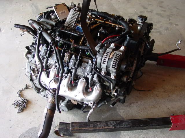
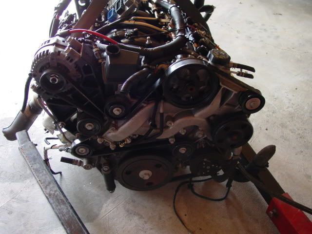
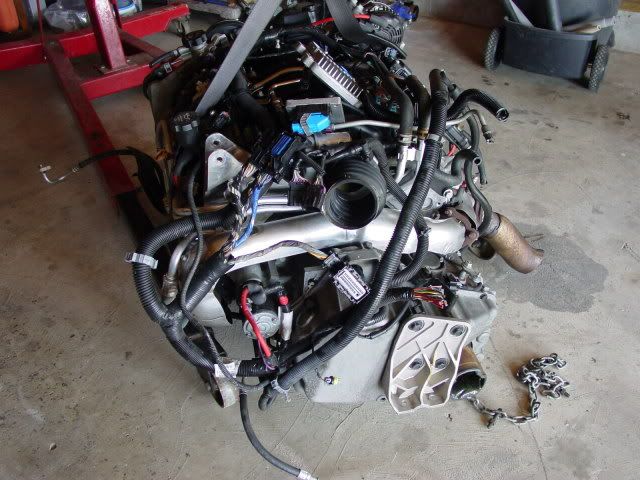
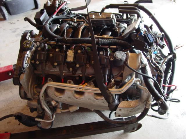
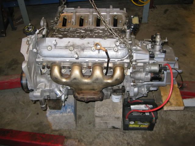
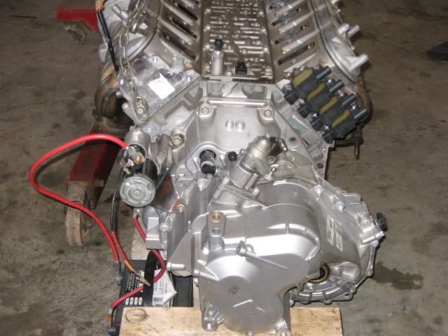
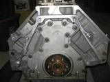
It all starts with a donor engine, so in late May/Early June 2010, I found a LS4 drivetrain from a 2007 Impala SS with 18K miles listed on LS1tech… a couple days later my wallet is $1000 lighter and this was taking up space in the garage:
During the research phase, I quickly realized that while 303hp in stock form isn’t a slouch, it seemed GM outfitted the LS4 with good heads and compression but with smaller/more restrictive intake and exhaust components than the other RWD LS(x) applications. If it made 303 hp with all these restrictions, I was curious to see what would happen when all these restrictive components are removed/upgraded.
So I spend some time figuring out what was different on the LS4 vs. the RWD LS(x) engines going component by component and compiled the following list of planned performance upgrades: **LS4 78mm MAF upgraded to 85mm MAF **LS4 76mm DBW throttle body upgrade to 90mm LS2 DBW throttle body **LS4 76mm Intake manifold upgraded to 90mm LS2 Intake manifold and matching LS2 fuel rail **LS4 28lb injectors upgrade to 34lb LS2 injectors (came with the fuel rail) **LS4 stock camshaft (197/197 .286/.286 @ 114LSA upgraded to a 224/231 .332/.338 @ 113 lsa (some will say this is too big…) **LS4 stock exhaust manifolds upgraded to LS7 hydro formed exhaust manifolds
These upgrades should do wonders to help the LS4 pump some air and make some power. All these upgrade components except the camshaft were purchased used off LS1tech.com or Ebay to help keep the upgrade costs down, but in total they were still higher than the initial engine purchase. Here are some pictures between the stock and upgraded hardware….
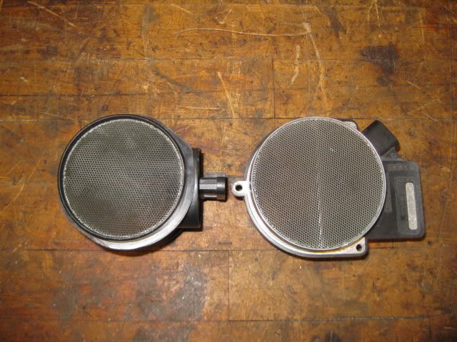
LS4 78mm MAF on the left and the 85mm MAF on the right. Both are 5 wire MAFs, but use different connectors.
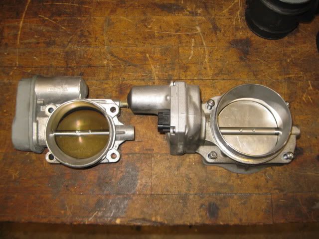
LS4 76mm DBW throttle body on the left and the 90mm LS2 DBW throttle body on the right. The LS4 throttle body is an 8 wire setup whereas the LS2 is a 6 wire connector.
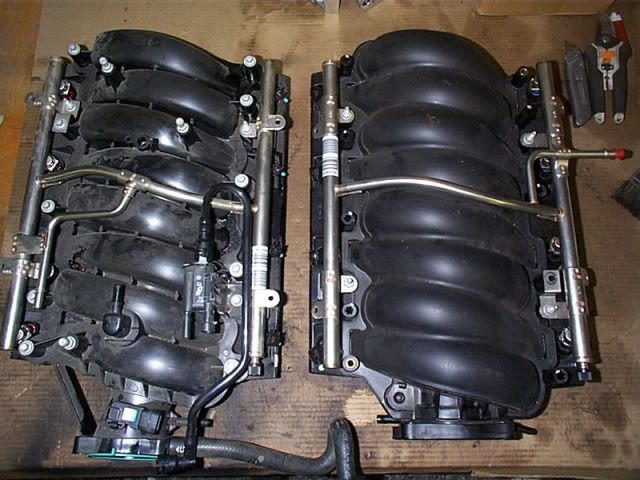
LS4 Intake manifold on the left and the LS2 Intake manifold and matching LS2 fuel rail on the right. Now some will say I should have used the LS6 intake because it flows better than the LS2, but the LS2 is a great improvement over the LS4, is cheaper than the LS6, and is better “looking” than the LS6 intake...
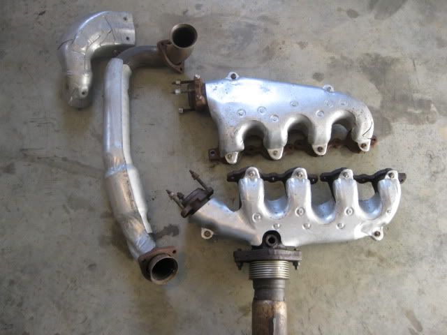
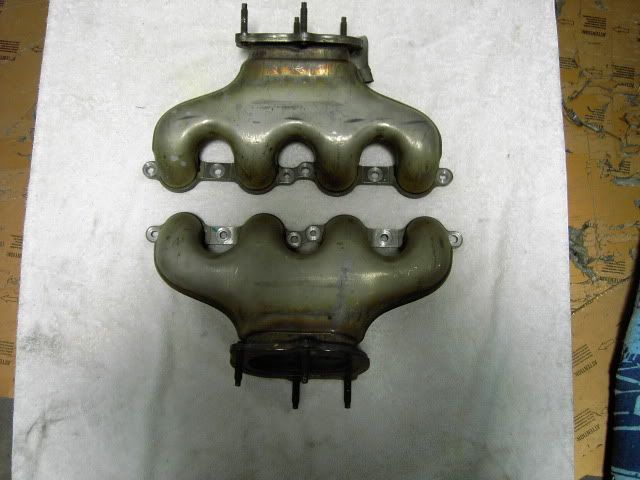
LS4 cast iron exhaust manifolds upgraded to LS7 hydro formed exhaust manifolds. What can I say, the LS7 manifolds are very nice looking, come factory on a 505hp engine, are hydro formed stainless steel with integrated heat shields and can be had for about $125… I just had to try them. They may cost me some low end torque (as well as the cam), but that is something most V8 Fieros have in excess anyway.
In addition to the focus on improving performance, the overall look of this install will be of paramount importance. I have never been a fan of engine or coil covers… so this install will not have any of those… just a simple, clean LS4/F40 install.
LS4/F40 Build Thread Table of Contents:
Pg1: Start Mount, flywheel discussion, mods for LS2 intake swap, coil relocation bracket, test fit in engine bay, DoD camshaft swap, cradle crossmember replacement, engine/transmission mounts and water pump modifications, fuel filter/regulator.
Pg2: Alternator and A/C relocation, belt tensioner, fabricating front engine/accessory mount, second test fit with water pump mods and air intake tube.
Pg3: Mock up of Saab intermediate shaft and exhaust manifolds, mounting tabs for engine/transmission mounts on the cradle – all drivetrain mounts fabricated, mock up turned down LS1 flywheel (could use for Getrag or F23 LS4 swap), experiment with 9 7/8” clutch from 3000GT-VR4, pictures of button head madness, modified SBC aluminum flywheel for LS4 application and 3000GT-VR4 clutch.
Pg4: Modified flywheel and 3000GT-VR4 clutch interfered with the differential bulge – aborted that part of the project, modified the LS7 exhaust manifolds and started fabricating the exhaust, started looking at another 9 7/8” clutch from a 4.0L Ford Ranger, purchased chunk of 6061 aluminum for custom flywheel, relocated factory frame notch on the driver side rail ¾” to the rear, modify cradle/crossmembers for better muffler clearance.
Pg5: Purchased a Spec Stage 4+ clutch for a 4.0L Ford Ranger, another test fit in the chassis for the exhaust, custom flywheel turned, milled, and assembled, disassembled harness LS4 harness.
Pg 6: Mockup of a RWD LS water pump, fabricated exhaust support brackets, fabricated brackets to use 88 front springs in the 88 rear suspension, rough measurements of flywheel/clutch combo shared, continued work on accessory/front engine mount, SF964F clutch arrived, accessory drive comparison stock vs. new setup, oil pressure sender, 3 wire temp sender, started looming some of the harness starting with the engine sensors, axle length mockup and discussion, started modifying the Saab intermediate shaft.
Pg 7: Continued work on intermediate shaft lengthening, decklid hinge box removal and hinge modification, swap ends on DS G6 axle for use on PS, test fit modified tripod and Corsica axle for the DS axle, 4 speed shifter mod for the F40 conversion and fabricate shifter bracket on transmission, welded and smoothed DS frame rail notch relocation, smooth firewall panel fabrication and installation, intermediate shaft bearing support.
Pg 8: Mockup coolant hoses, tear down for painting of fabricated parts, sanding/smoothing of engine bay, clean up garage for customer car, clutch comparison fiero Spec Stage 3+ to Ranger Spec Stage 4+, some pictures of the SBC/Getrag customer swap, discussion about DoD, pictures of 4.3 swap I was working on as well.
Pg 9: SBC/Getrag startup video, pictures of LS4 oil pan and discussion about DoD delete, R&D 13” brake kit for the 88 Fieros.
Pg 10: Back working on LS4, installed new timing chain tensioner, assembled painted parts, mock up of modified SBC water pump (from 4.3 swap) on the LS4, SBC harmonic balancer comparison, pictures of 13” brake kit brackets and rings and rotors, longer flywheel bolts, flywheel installation with some overall dimensions, Spec Stage 4+ clutch installation, corner weights for the engine/transmission on the cradle.
Pg 11: Cut up a parts car, mock up some coilovers for the 88 front suspension, wheel fitment measurements, 4 ¾” rear wheel bearing modification, rod end lateral link upgrade, lateral link relocation bracket development.
Pg 12: Switched from the blue 88 GT Clone chassis to the 88 Black/Yellow Notchie, drill 88 front wheel bearings for 5 x 4 ¾” pattern, lateral link relocation kit launched, mockup some 17/18 corvette wheels and verify clearance issues, pull rear suspension in 1 5/8” to fit a 18 x 10.5 wheel under the stock body panels, relocate the top of the strut 1” inboard, clean up engine bay on new chassis and move frame notch and install modified decklid hinges, pickup another 88 GT clone for a DD, buy a house and move everything, drawing for LS4 to LS2 throttle body adapter, mount ECM, start harness work again, fab up A/C lines, mockup plug wires.
Pg 13: Work on MAF, muffler heat shield, plug wires, plastic air intake, more harness work, heat shield for A/C lines, catch can installation, PCV routing, wiring diagrams for 88 Fiero w/ LS4/F40 and E67 ECM, DBW pedal installation, 500 connector harness relocation, fuel tank vent mod, fuel filter installation, HTOB connector to fiero line, F40 factory transmission fluid.
Pg 14: 4” cold air intake fabrication, A/C hose ferrules, interior harness wiring, Dyna-BATT battery relocation, fabricate hard coolant lines and rubber hose routing, Champion radiator installation.
Pg 15: Champion radiator installation, battery relocation, coil air intake coating, heater hose connection to water pump, smooth firewall panel mockup, coolant hose mockup, smooth/sand engine bay, paint engine bay and smooth firewall panel and hinges, reinstall drivetrain (last time).
Pg 16: rework coolant hard lines, power up ecm and work on base tune, debug DBW issue, first start of LS4/F40, work on Range selector codes.
Pg 17: Install clutch switch, install C4 vette seats, fabricate laptop stand, modify rear struts for coil overs, paint rear suspension parts, install front hood support for rear decklid support, modify calipers to fit 13” rotors under 16” wheels, install 13” brake kit, trim front bump stops, install front Koni shocks, move car out of garage under its own power, fixed Tach issue, debug belt squealing issue – replaced water pump and rebuilt alternator.
Pg 18: Work on electric fan settings, calibrated speedo, changed belts and eliminated the belt squeal, video of driving the car, replaced burnt plug wire (boot was not properly seated), installed the stock LS4 injectors and fuel rail, more work on the Range Switch code, continue tuning the car.
Pg 19: Cleaned the tank of rust, installed new fuel pump and filter/regulator, couple more videos of revving the engine and driving the car, decibel readings for the car, invisible hood vent modification.
Pg 20: Upgraded to larger air filter and installed LS7 MAF, installed VW 6 speed shifter knob, plasti-dipped over the yellow paint, swapped to a non-sunroof panel and painted it black.
Pg 21: Installed sound deadening material to doors, firewall and roof, fixed mirrors and door panels, installed smooth sail panels, broke belt tensioner, installed FJF springs up front, installed lateral link relocation brackets, pulled down 29.3 mpg on first interstate trip.
Pg 22: Corner weighed the car, dyno’d the car, customer’s SBC/F23 car arrived for rework, plans for new garage.
Pg 23: Mounted fire extinguisher, Took the car to LS Fest and ran ¼ mile, autocross & 3S with it, video of autocross, broke shift cable, pictures of F40 shifter assembly removed from transmission.
Pg 24:
[This message has been edited by fieroguru (edited 03-21-2014).]
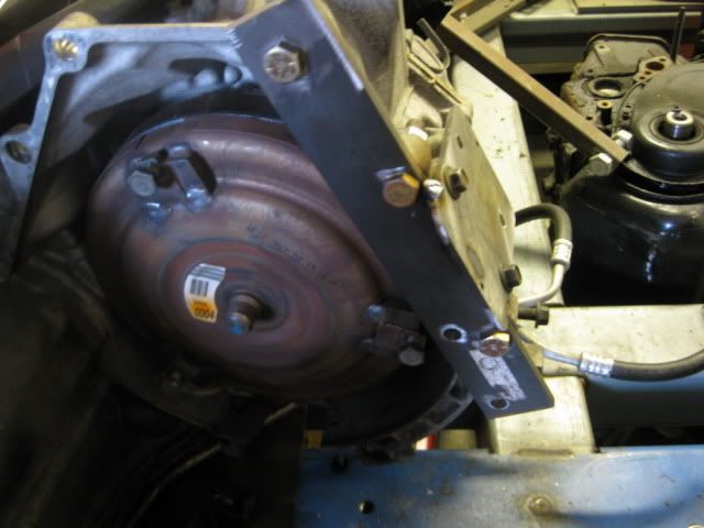
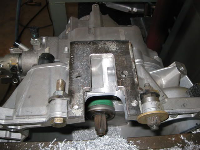
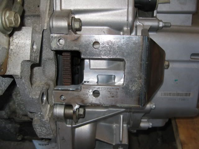
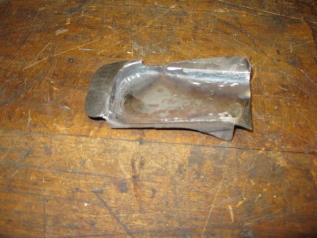
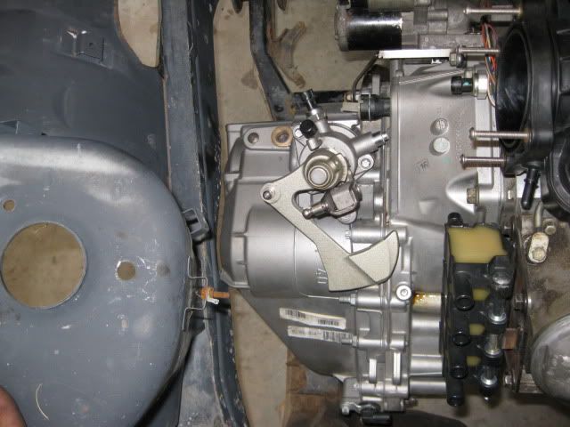
Since the LS4 never had a starter provision on the engine side, the F40 needed a starter provision on the tranny side. Nothing like cutting a hole in a brand new transmission… but it needed to be done. Using the 4T65E-HD, a fixture was mocked up so the starter pad shape and location could be transferred to the F40. Then it was a matter of removing enough aluminum on the F40 to allow the new starter mount to be properly positioned. End result is a bolt on starter mount for the F40 transmission that will spin the LS4.
guru... does the f40 and the new 2010 cobalt f23 getrags have the same engine bolt pattern? do you know? thanks.
I assume the cobalt uses the Ecotec for all engine levels... if that is the case, then no the F40 and the ecotec F23 do not have the same bellhousing. The F40 uses the GM Metric FWD pattern common with the fiero Getrag, Isuzu, Muncie, 125C, 4T60 and 4T65
Another significant hindrance is the flywheel for a couple of reasons. Since I am keeping the stock LS4 starter position, I must keep the LS4 142 tooth ring gear (11.9” diameter). All available RWD manual flywheels for the LS(x) engine family are 168 tooth (14.1” in diameter) and these will not clear the bellhousing bolt pattern, let alone fit within the transmission. The other challenge is the LS4’s crank flange is flush with the bellhousing surface and all RWD LS(x) engines have the flange protruding into the bellhousing. So the LS4 will also need a thicker flywheel than its RWD counterparts as well as the F40 needing a thicker flywheel due to its design around a dual mass flywheel.
So the LS4/F40 combo will require a relatively small diameter flywheel (under 12”) that is approximately 2.0” thick… Unfortunately, I have not been able to find a stock flywheel with these criteria.
There are 3 flywheel solutions as I see it…
**Full bore custom aluminum flywheel… probably cost you about $600 - $750. **Turn down a stock LS1 flywheel to accept the 142 tooth ring gear, drill it for the Fiero pressure plate pattern, then use the Archie F40 spacer plate for the 2.8 V6. The LS1 flywheel on the LS4 has the same “approximate depth” into the bellhousing as a stock 2.8 V6, so if the spacer works on a 2.8, it should work for the LS4 as well. **Hybrid approach… which is what I did. LS4 flexplate, .400” LS(x) crankshaft spacer (off the shelf item for under $50) and a highly modified aluminum flywheel from a C4 LT1/ZF6 application. The end result is a 14 lb flywheel assembly that is about 1.95” thick.
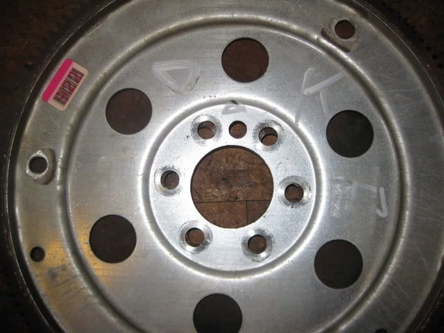
Here is the LS4 flex plate sitting on top of a 86+ SBC flex plate. You can see the difference in the hole locations.
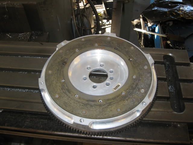
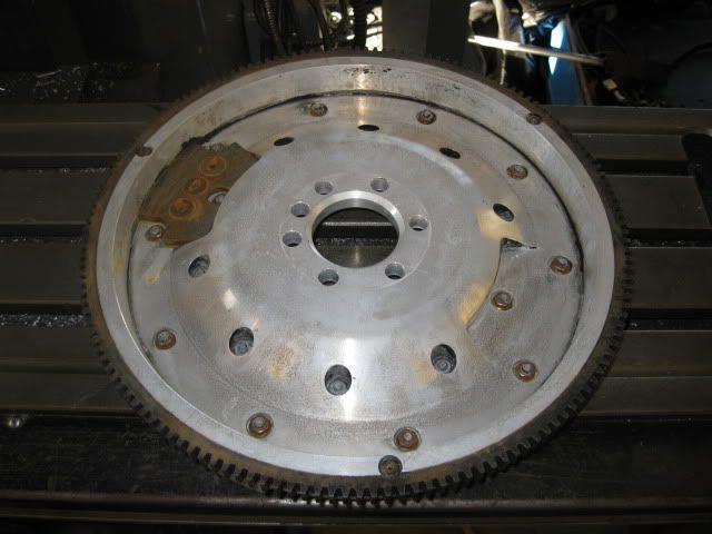
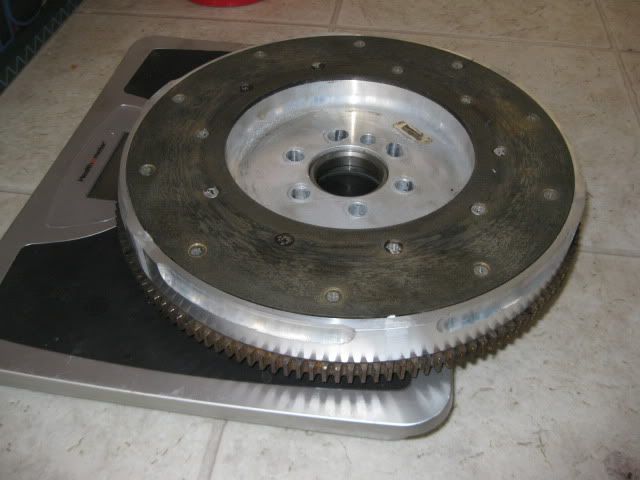
C4 LT1/ZF6 Fidenza aftermarket flywheel (picked up used). It is quite thick and has a removable balance plate on the back side to restore the flywheel to neutral balance. It is also very open on the back side to reduce overall weight, but also made the outer rim too small to support the 142 tooth ring gear.
Flex plate, spacer and modified flywheel. It weighs 14 lbs as an assembly:
[This message has been edited by fieroguru (edited 12-13-2010).]
so the ls4 has the same bolt pattern as a fiero getrag?
Yes:
From my perspective, there are benefits and drawbacks to the LS4... Benefits: 1: It comes with the FWD metric pattern and will physically bolt to a fiero transmission w/o any need for an adapter plate (but you have the starter issue). 2: Since it does not come with the RWD/SBC patten, they can be had dirt cheap compared to the other aluminum block LS(x) engines (try finding an 18K mile LS1/LS2/LS3 complete with tranny for $1000). 3: They come with the 243 heads which are the best stock cathedral port heads. 4: The accessory drive is more compact... but far from perfect. 5: It is a DoD engine and the 2007+ engines with the 58 tooth cranks can be retrofitted with VVT cam phasers.
Downsides: 1: Stepchild of the LS(x) family with minimal aftermarket support. 2: No starter provision on the engine. 3: No factory manual transmission application. 4: DoD limits camshaft choices and complicates the intake swap options (and without a better intake, a cam upgrade is pretty much a waste) 5: Accessory drive is overly complicated and makes alternator placement an issue. 6: It is only 5.3L 7: Engine is ugly w/o the engine cover.
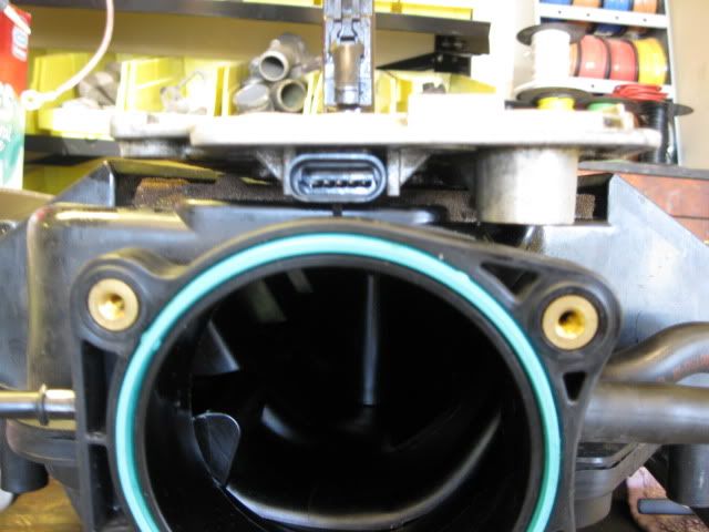
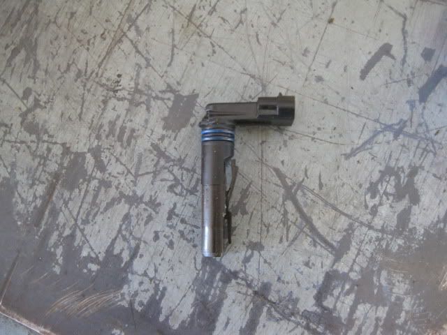
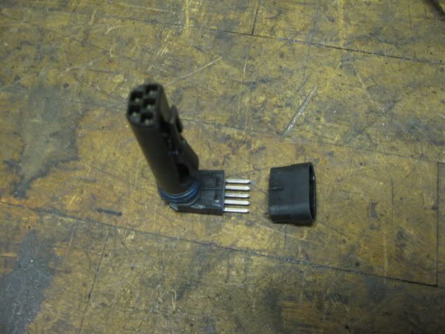
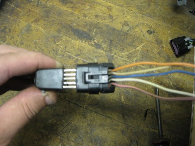
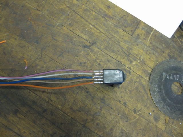
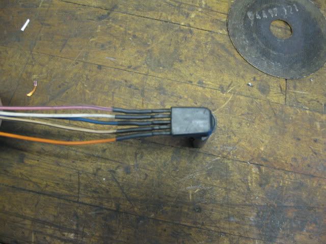
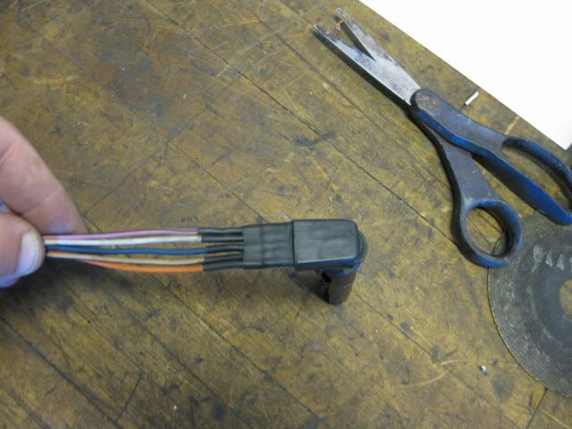
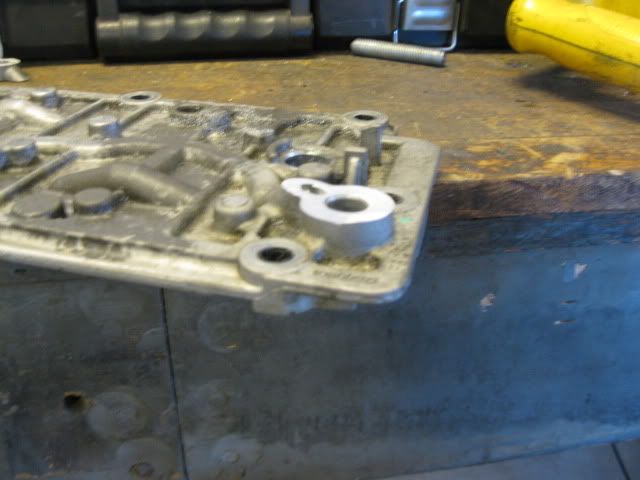
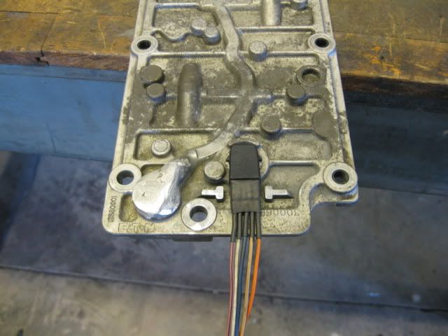
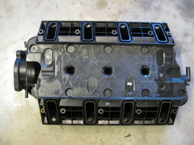
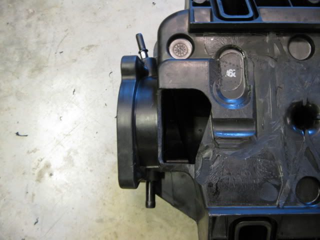
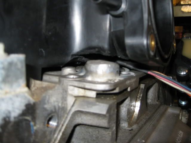
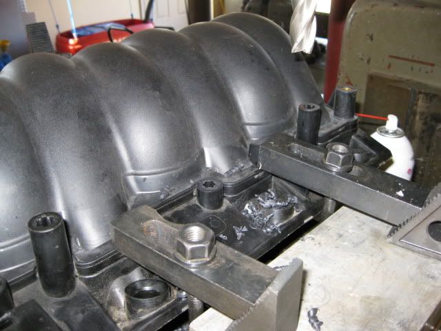
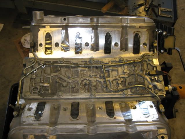
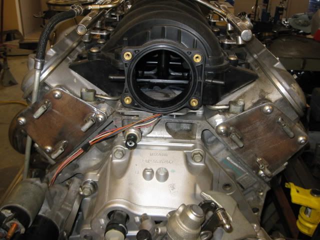
This swap needs to look good without any engine covers… so first thing that needs to go is the LS4 intake… it is just ugly (and a restriction). Now while the LS2 intake isn’t as good as the LS6 one, it has very clean lines for use without any covers. The problem is the LS2 intake will not fit the stock LS4 DoD valley cover without major clearance work (it fits just fine with some minor work when used with non-DoD valley covers - Archie’s swaps do this all the time). Even with the OPSU boss cut down about 1/2" in this picture, you can see the valley cover needs to come down another 3/8" to be able to fit... this is going to take some work. First thing under the knife was the connector. Right behind the flange for the connector, I gently cut through the plastic and eventually was able to pry the end off exposing the 5 terminals: Call me finicky... but I wanted to know the OEM wire colors for this connection so the new wires (recycled from other GM harnesses) can match. New wires (about 24" in length - way too long) soldered to the appropriate terminals: Heat shrink x2:
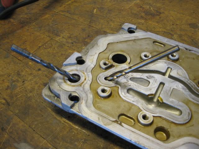
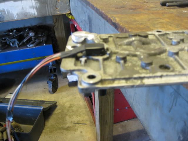
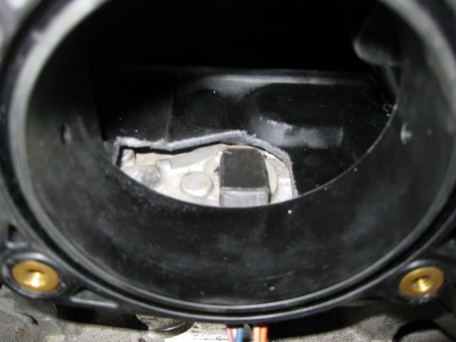
Now back to the OPSU - it will be relocated entirely. I had already cut it down about 1/2" and cut it down another 3/8" to expose the oil passage while still leaving material to drill a new oil passage. New oil passage: Then the top side of the OPSU boss was welded up to close up the passages. Here is a finished pic of the welded OPSU and the modified connector:
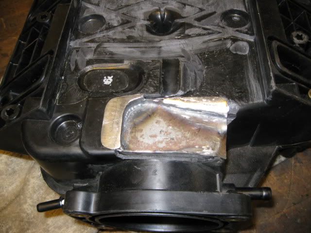
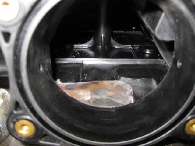
Sadly, the LS2 intake still isn't going to accept installation without modifying the intake. Lower ribs flattened and the area of the connector and OPSU was cut open (this also give me room for the vent upgrade): But now it can be installed w/o interference: Patch panel fabricated to seal the hole: This patch panel was glued in place inside and out.
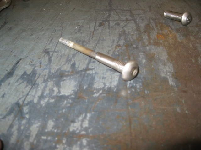
Just because I thought they would look better, I cut the intake manifold bold bosses down about 1” I have a sickness for stainless steel button heads and even at this shorter length, they just do not exist in the proper length/thread... so I made some using some other metric stainless steel button heads. Drilled the center, cut the OEM bolts the proper length, pressed them into the bottom of the button heads, weld then together, grind off the excess...
Even have button heads for the fuel rail and throttle body:
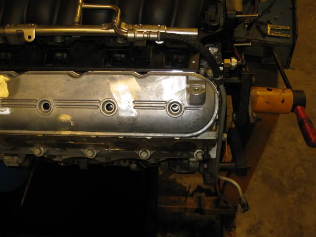
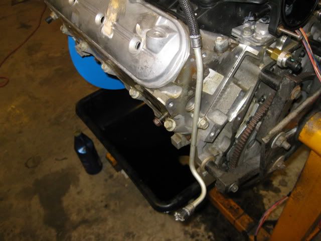
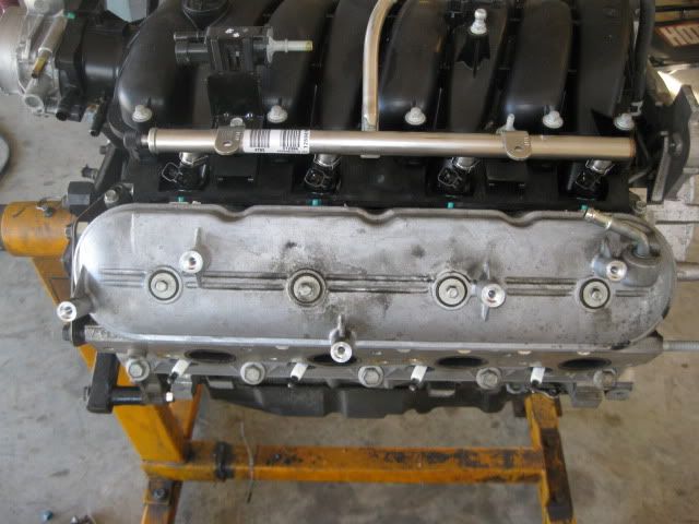
The last intake manifold modification was to bend the stock LS2 fuel rail so the fuel line will not cross over the valve cover (like the stock LS4) and then bent the original LS4 fuel line to go down the end of the head and exit down low away from the exhaust. In this picture you can see where the OPSU was relocated - drilled/tapped the oil passage below the valley cover:
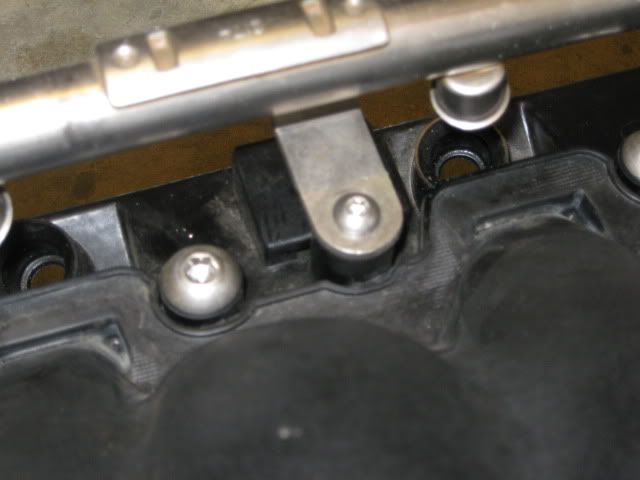
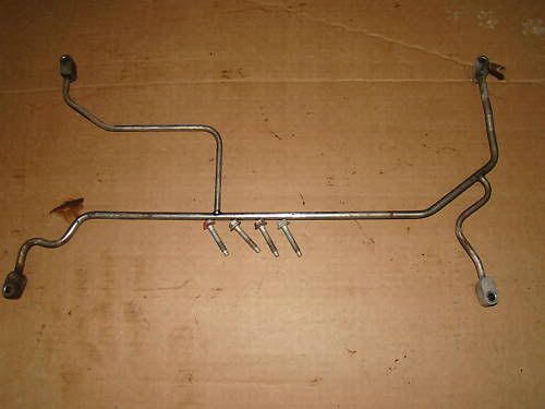
One last upgrade while the intake is off… I plan to wail on this engine once installed and it might see some NO2 at some point, so I went ahead and installed the 4 corner vent setup from a 6.0L truck just to ensure cylinders 7&8 have the best chance for equal cooling. It took some slight bending of the lines to route them around all the raised bosses and oil passages and I bent the exit tube to be vertical so it clears the intake. 2 bolt bosses for the DoD stuff under the cover needed cut down, but not far enough to touch the bolts. Some RTV should seal them back up. The bottom corner of the LS2 intake (the triangle part that rests between the heads and the valled cover) needed about 1/2" trimmed from it at the corner to clear the tube in the upper right hand corner of the picture. But now it fits!
[This message has been edited by fieroguru (edited 12-13-2010).]
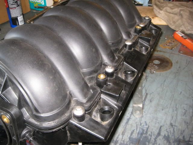
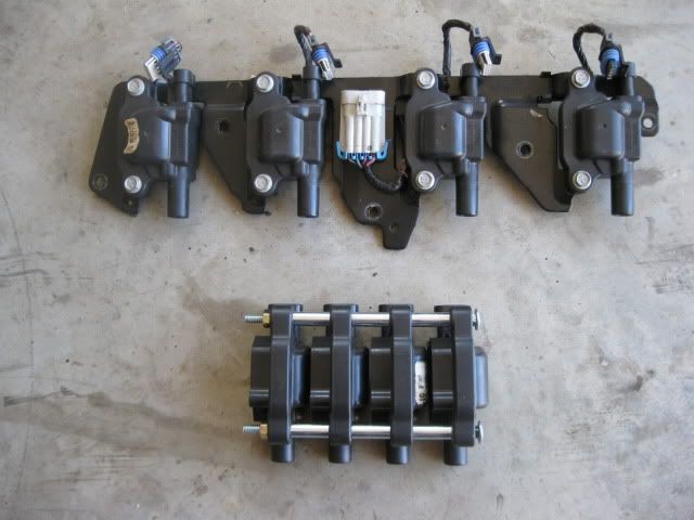
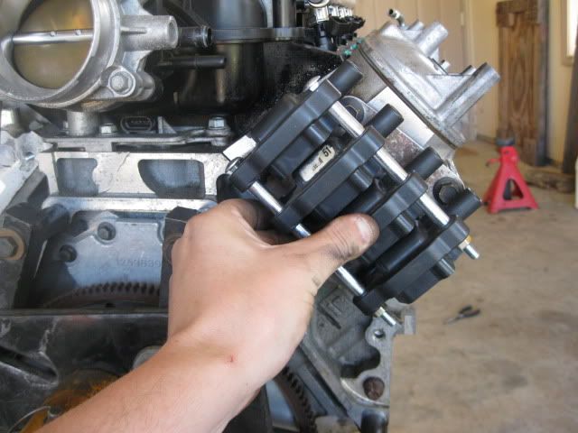
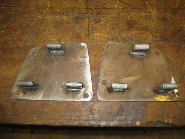
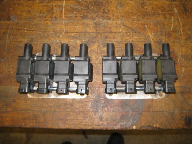
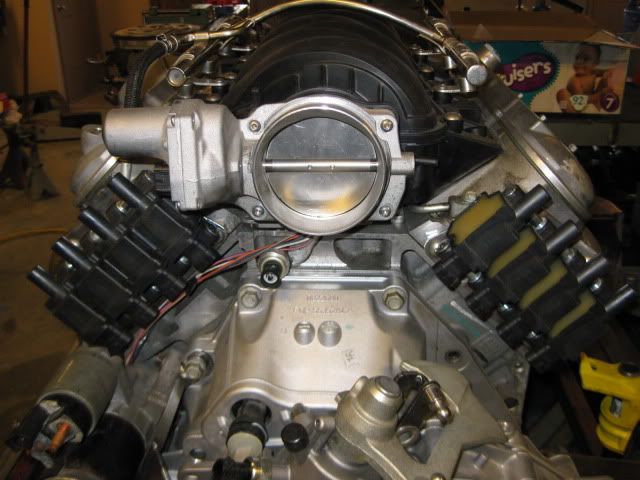
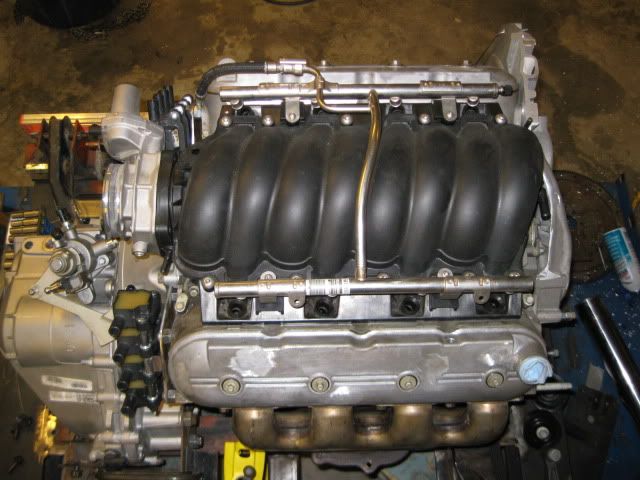
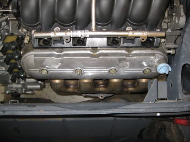
The other significant beautification modification was to do something with the unsightly coil arrangement and collection of wires over the valve covers (valve covers are to be seen, not covered). After some disassembly and brainstorming, the LS4 coils fit together quite nicely when mounted with some off the shelf spacers from Lowes: Then it was a matter of determining where on the engine this more compact coil pack could be positioned. Had I used headers, along the oil pan would have made them disappear all together, but since the LS7 manifolds do not have room for the plug wires to come from underneath, I settled on this area: Some 1/8” scrap plate and a little fabrication and I had these:
The really nice part about the coils being in this location is all the harness connectors point down to the bellhousing area, so the harness will be mostly hidden from view. Once the coils were off the valve covers, it was time to cut down the bosses, weld up the holes and smooth everything to get a nice clean look. Here is good inspirational shot of the intake, coil and valve cover work so far. The stock LS4 fuel line will pass behind the front coil pack and disappear from view. The only wiring that will need to be on top of the intake will be for the injectors and those will be ran under the fuel rails out of sight as well.
[This message has been edited by fieroguru (edited 12-13-2010).]
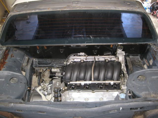
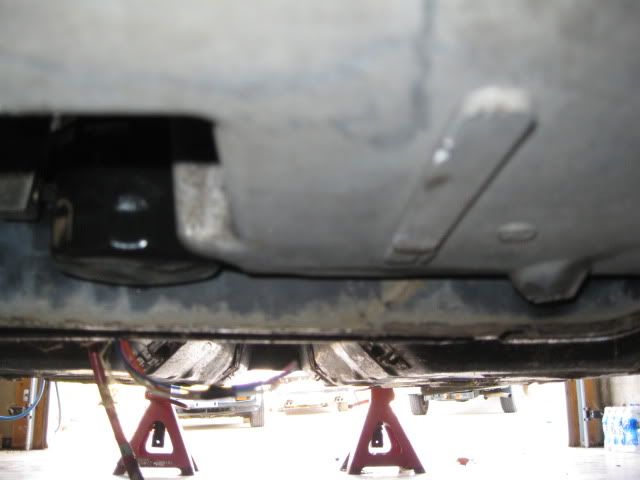
The LS4/F40 combo is somewhat misleading in how much room most would think there would be to install. Truth of the matter is the LS4/F40 combo is a very tight fit with the factory water pump and an unmodified 88 cradle. My mockup chassis has bolt in hinge boxes, so I left them out for this test fit. That is the only deviation from a 100% stock 88 engine bay (other than the battery tray). The elevation and engine placement in the pictures is dictated by clearance issues in several areas. Once these clearance issues are addressed the engine placement/elevation could be moved around a little more.
Overall engine bay view :
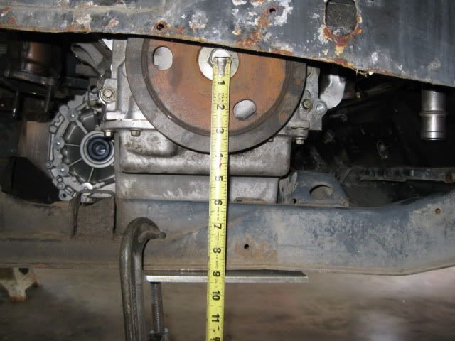
The crankshaft centerline is about 9 1/8" from the bottom of the 88 cradle (height was dictated by clearance issues, but with some modification it can go lower):
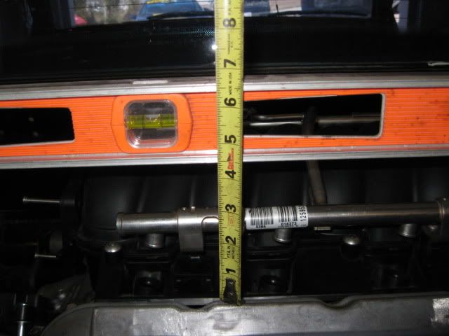
Another reference to elevation is this measurement from the flat top of the strut towers to top most portion of the valve cover:
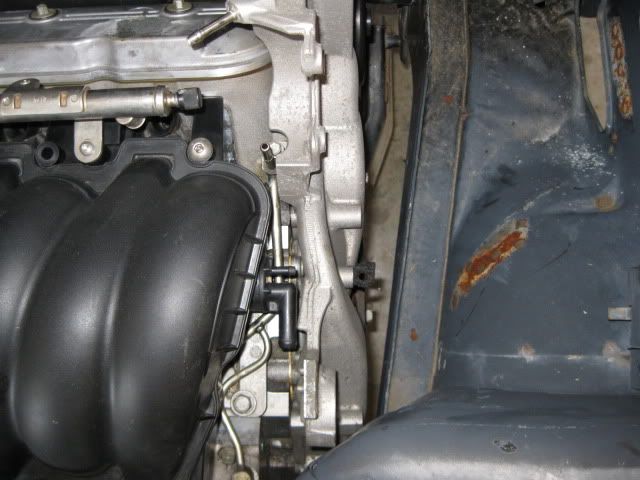
On the engine side of things there are clearance issues with... Oil fill with dog bone bracket:
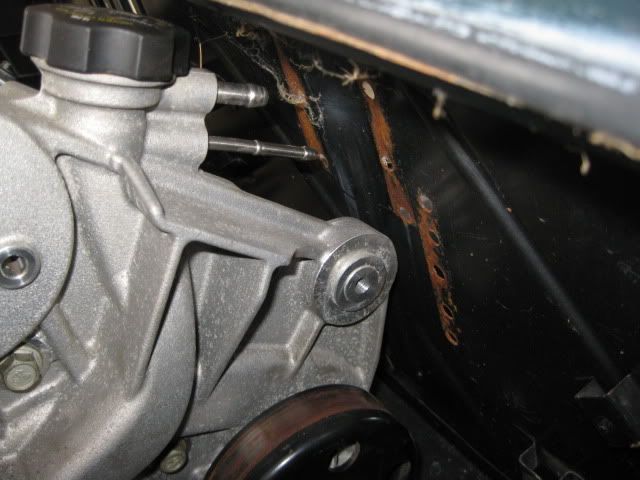
Water pump bolt with strut tower:
Idler bracket with strut tower and balancer to passenger frame rail:
Coolant fill with hinge box and front idler with firewall:
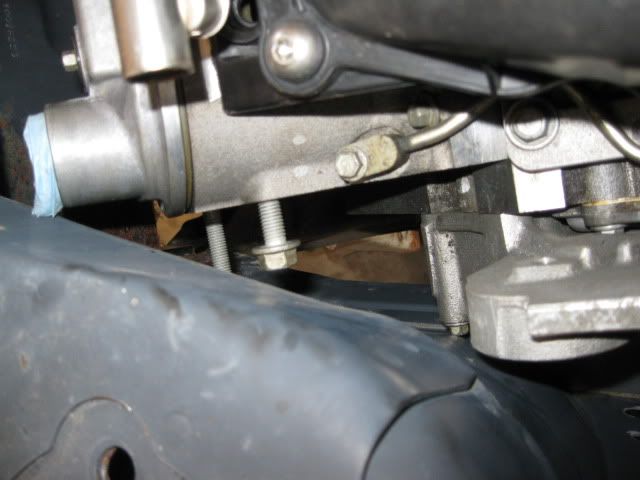
Oil pan and engine mount bracket on cradle (this and the tranny to frame rail dictated the engine elevation to clear everything):
Oil filter to front cradle cross member:
Front exhaust manifold to the double firewall section:
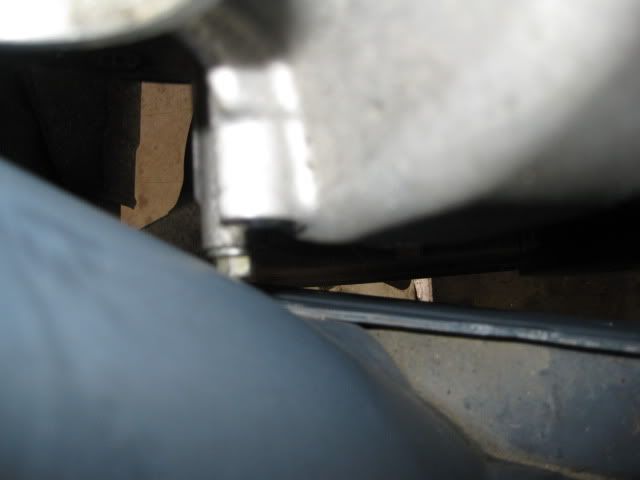
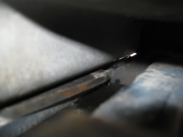
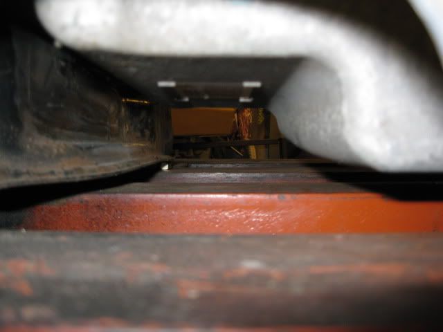
Oil pan to bottom of cradle (about 1"):
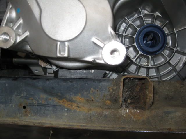
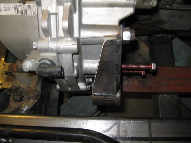
Moving on to the transmission side of things: Tranny to driver side frame rail (it is touching):
Tranny to the cradle side rails (notice my shim to level the engine/tranny - this will be the elevation limiter before the bottom of the cradle):
Other important dimensions: Valve cover to rear firewall = 2 3/16" C/L crank to C/L of front cradle bolt = 15 5/8 (measured horizontal, not angular) Bell housing face is offset 5 1/4" from the cradle centerline to the driver side
Here is a good comparison between the axle centerlines locations between the F40 and the 4T65. The elevation is pretty close, the F40's axle is close to 2" closer to the engine than the 4T65:
As you can see in the pictures where the engine is sitting is dictated front to back by the idler pulley to firewall & Oil filter to cradle in the front and idler pulley to strut tower clearance to the rear. Side to side placement is tranny to DS frame rail on the left and water pump bolt to the strut tower on the right. Elevation is dictated by the stock cradle engine mount to oil pan interference.
Moving the engine forward will gain more clearance side to side and to the rear of the engine. This is what all the LS4/4T65 swaps done to date have done by notching the cradle for the oil filter and relocating the front idler back an inch or two. Removal of the stock engine mount on the cradle will allow the engine to lower about 1/2" and to go any lower would require some work to the tranny case or cradle side rail.
When it came to the camshaft, there were a few options I considered:
1: Ditch all the DoD stuff and run any LS(x) cam I wanted… lots of work and cost to replace the lifters, oil pump, valley cover, etc, and the heads have to come off… which always leads to more upgrades. Downside/Upside is you lose DoD… but have an near endless selection of camshafts to pick from.
2: Stock LS4 cam (193/193 .283/.283 @ 114lsa – Non DoD lobes) with 1.80 or 1.85 rockers – this is the least expensive and simplest approach, but gains would be minimal (10-20hp). Several LS4 guys have done this on LS1 tech.
3: Stock G8 cam (197/207 .278/.282 – non DoD lobes) with 1.80 or 1.85 rockers. Slightly more expensive than the using the stock cam and requires a camshaft swap, but provides more duration vs. stock LS4 and was a factory DoD camshaft. Probably would result in a slight improvement vs. the stock cam and rockers, bust still very mild.
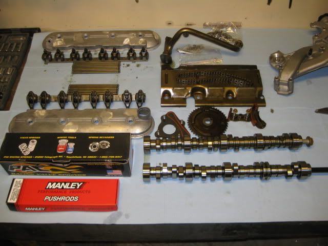
4: Go with a much larger DoD compatible aftermarket camshaft… this is the route I took. This camshaft was designed for DoD and comes with the springs, pushrods, chain tensioner… only downside is they would not tell me the specs. The one guy on LS1 tech who installed this cam and said it was big (peak power in the 6800-7000 range), probably too big, but if he could still get his 3400 lb automatic beast moving with the cam. It has also been installed in some 5.3 full size trucks… so I figured it would be OK in a 2900 lb fiero with manual transmission and a stump pulling gear ratios. This cam was advertized to provide a 54 hp increase on the 6.0L… so for better or worse I went big.
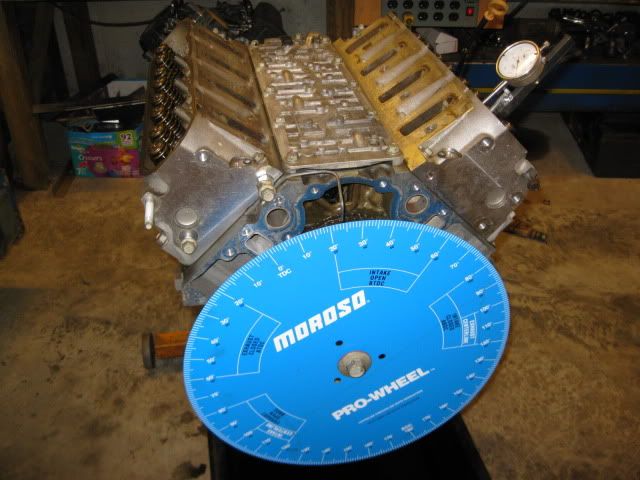
Since they would not tell me the specs… I just HAD to find out what they were, so an 18” degree wheel was added to my tool collection.
First order of business to degee the stock LS4 cam on cyl #1 (which is a DoD cylinder which might explain why my measurements are slightly different than the internet specs… I took a degree reading at .006, .050 and every .025 up to max lift up and down for intake and exhaust). Stock LS4 camshaft specs: 197/197 .286/.286 @ 114LSA Stock LS4 events @ .050 lobe lift: IVO (BTDC): -18 IVC (ABDC): 35 EVO (BBDC): 31 EVC (ATDC): -14
I never confirmed the G8 stock specs… but here they are for comparison Stock G8 DoD camshaft specs: 197/207 .278/.282 IVO (BTDC): -17 IVC (ABDC): 37 EVO (BBDC): 40 EVC (ATDC): -12
I did the same for my aftermarket camshaft and it was 224/231 .332/.338 @ 113 lsa but I also noticed it was really not what I was expecting. Here is an overlay of the two cams with the larger/wider lobes being the aftermarket one. As you can see everything was moved much later in the cycle.
So I spent quite a bit of time checking out other cams of the 224 to 230 duration, comparing where the valve events are for those camshafts and where mine were to figure out a better position in which to install the camshaft. A couple of the comparison cams are as follows:
MTI Stealth II 224/220 (everything at .050 lobe lift) IVO (BTDC): -4 IVC (ABDC): 48 EVO (BBDC): 46 EVC (ATDC): -6
Comp Cams xer 224/230 (54-444-11 XER273HR) IVO (BTDC): -1 IVC (ABDC): 45 EVO (BBDC): 50 EVC (ATDC): 0
After much thought and discussion with the other guy running this cam, I chose to install the came with the approximate valve events at .050” lobe lift: IVO (BTDC): -3.5 IVC (ABDC): 47.5 EVO (BBDC): 46 EVC (ATDC): 5.5
This installed position places the new cam intake centerline right on top of the stock LS4's and pulls the IVO event back down to a more reasonable level for the 5.3 (it is still pretty high). This could be a major mistake, but only time will tell…
[This message has been edited by fieroguru (edited 01-03-2011).]
4: Go with a much larger DoD compatible aftermarket camshaft… this is the route I took. This camshaft was designed for DoD and comes with the springs, pushrods, chain tensioner… only downside is they would not tell me the specs.
Wow... I would NOT have bought a cam from an outfit that wouldn't give me at LEAST *BASIC* info on the duration, lift and lobe sep. The fact that they do that and expect people to buy it black box is INSANE. If any outfit told me that, I'd tell them their competitor is getting my money. Holy cow. The fact that people buy it black box and just install it (without degreeing it as you've done) is even more insane. Do all the cylinders degree the same? In your shoes I would be *highly* suspect of any quality issue with that cam, from consistency of grind from lobe to lobe to material to heat treatment/surface hardness to straightness. I wonder if the outfit even knows what specs they're selling. Are your prepared to lunch your engine if that cam wipes a lobe into your oil pan? I know it's a roller, but crappy material is still crappy material. I hope for your sake it's actually made of steel and not some tin plated lead casting out of China. Is it at least magnetic?
[This message has been edited by Will (edited 12-14-2010).]
Wow... I would NOT have bought a cam from an outfit that wouldn't give me at LEAST *BASIC* info on the duration, lift and lobe sep. The fact that they do that and expect people to buy it black box is INSANE. If any outfit told me that, I'd tell them their competitor is getting my money. Holy cow. The fact that people buy it black box and just install it (without degreeing it as you've done) is even more insane. Do all the cylinders degree the same? In your shoes I would be *highly* suspect of any quality issue with that cam, from consistency of grind from lobe to lobe to material to heat treatment/surface hardness to straightness. I wonder if the outfit even knows what specs they're selling. Are your prepared to lunch your engine if that cam wipes a lobe into your oil pan? I know it's a roller, but crappy material is still crappy material. I hope for your sake it's actually made of steel and not some tin plated lead casting out of China. Is it at least magnetic?
I had numerous conversations with this vendor prior to purchase and was able to get them to share that the intake was in the mid 220's and the exhaust was low 230's. Their argument was that they spent quite a bit of dyno time and R&D development for a DoD compatible camshafts and didn't want to advertise the specs for others to copy... While I did not like it, I also can't argue with their view point either. If they hadn't been the only DoD camshaft supplier at the time, I probably would have gone with a cam I knew the specs on.
The actual cam was manufactured by Comp Cams using their AFM cam core, so I have little concern from a manufacturing standpoint.
Originally posted by fieroguru: Their argument was that they spent quite a bit of dyno time and R&D development for a DoD compatible camshafts and didn't want to advertise the specs for others to copy...
While that may be true, I don't consider it a valid argument. There's *SOOO* much more to lobe design than the traditional "five number" specs. The guys in the Advanced Engine Tech section of Speedtalk frequently argue over velocity profiles, acceleration profiles, fitting polynomials to a lift curve while smoothing the 6th derivative... There's absolutely no harm in releasing the "five number" specs (and it just might get them more business) unless that's all they know about the lobes, in which case I'd still be worried.
Originally posted by Will: What makes a cam "DOD Compatible" anyway?
The DoD profile has a lower lift limit due to the special lifters. There are also some other practical limits for the LSA and duration. Too much and there's a possibility of stalling out on the highway when the DoD kicks in, given the fact that you just lost half the cylinders.
There are 3 key camshaft requirements for the DoD lifters: In 4cly mode the DoD lifters must be able to fully collapse internally to allow the valve to remain shut as the lifter rides the cam. The opening and closing rate must not be to agressive. The sping pressure can not go beyond a certain point.
The last two are interrelated and have to do with the locking pin in the lifters for V8 mode. If these factors are not taken into consideration, you will fail the DoD lifters in under 5K miles. After reading countless threads of people "trying" other factory cams (even the stock LS6 cam) and ruining the DoD lifters, I figued it was best to go with a proven design (from a DoD perspective) vs. taking a gamble with an unproven design. This particular cam has been on the market for 2 years now with around 100 installs and so far none have had any lifter issues. So while the cam isn't perfect from a spec standpoint, I shouldn't have to worry about killing the DoD lifters.
Most camshaft suppliers choose not to spend the time R&Ding the cams for the limited DoD market and instead have chosen to offer DoD delete kits to replace everthing needed so you can run one of their many off the shelf cams.
Ok, so the lobe lift has to be less than the travel of the "disconnected" lifters. What "fails" in the DOD lifters? Does the pin actually shear? So it has to be a gentle ramp, "lift rule" lobe... interesting. You said one of your sources told you it was a "big" cam? Sounds to me like the gentle ramp rate means that the seat-to-seat numbers are much bigger than the .050 numbers, so it has much more overlap than a "normal" LSx performance cam with the same .050 duration.
Ok, so the lobe lift has to be less than the travel of the "disconnected" lifters. What "fails" in the DOD lifters? Does the pin actually shear? So it has to be a gentle ramp, "lift rule" lobe... interesting. You said one of your sources told you it was a "big" cam? Sounds to me like the gentle ramp rate means that the seat-to-seat numbers are much bigger than the .050 numbers, so it has much more overlap than a "normal" LSx performance cam with the same .050 duration.
I haven't seen any disassembled views of a failed DoD lifter, but when they fail they make a hell of a racket. From what I have read the seat to seat overlap isn't much of an issue (not open enough to allow much air flow)... the stock LS4 cam has 87 degrees of overlap at .006, and -33 degrees at .050. My cam has 58 degees of overlap at .006, but does have 3.5 degrees of overlap at .050... it probably will have a some what choppy idle.
If you look at the diagram of the lobe graphs posted above, you can see the aftermarket cam has a similar opening curve for the first several lift points, then it speeds up slightly, lifts higher, stays open longer, then closes very similar to stock. The real difference is duration at .200 lift. The stock cam spends 106 degrees with the intake lift greater than .200, my cam has 144. A 224 came with more agressive lobes probably has a duration at .200 greater than 150 because it gets to that point in fewer degress on the ramp up.
This cam on the 6.0L engines installed dot to dot works in 4cyl mode (they say they picked this cam due to it performing best in 4cyl mode vs. the others they tried). The other LS4 guy running this cam installed it dot to dot. He has commented on his car peaking power just under 7K rpm and of a significant loss of lowend torque (still able to spin the tires, just 0-60 is slower). Based on that and the cam originally be designed around a 6.0L with more cubes/lowend torque, I installed my cam advanced of dot to dot to bring back a little on the lowend (picked up some dynamic compression ratio as well) and lower the peak RPM down some.
[This message has been edited by fieroguru (edited 12-16-2010).]
Good thing KY doesn't do tailpipe sniffer. Also, I'd wager that cam was spec'ed for a 6.2, or at least a 6.0, back when they were first playing with it. At least your 5.3 can be bored to 5.7, that'll help some. I'm fairly sure you're not gonna be trying any such thing anytime soon, but it is an option. And about as cheap as buying yet another cam, plus the then-necessary tune, which the extra cubes wouldn't necessarily mandate. Maybe if it maxed out your injectors, but otherwise... Anyway, just new gaskets, a few of which another cam swap would require anyway, plus a few bolts, bore / hone, a set of good used LS6 pistons with rings, and re-balance the crank. LSx bearings are re-useable unless damaged.
[This message has been edited by Isolde (edited 12-16-2010).]
Good thing KY doesn't do tailpipe sniffer. Also, I'd wager that cam was spec'ed for a 6.2, or at least a 6.0, back when they were first playing with it. At least your 5.3 can be bored to 5.7, that'll help some. I'm fairly sure you're not gonna be trying any such thing anytime soon, but it is an option. And about as cheap as buying yet another cam. Just new gaskets, a few of which another cam swap would require anyway, plus bore / hone, a set of good used LS6 pistons with rings, and re-balance the crank. LSx bearings are re-useable unless damaged.
Especially since the car will not have catalytic converters! The cam was designed aroung the G8 6.0 DoD application.
I do not know if you noticed it while you had your LS4 apart but the LS4 block is actually longer than the other RWD Ls(x)'s. The FWD pattern is actually raised from the RWD pattern. This difference and the 3mm shorter crank is what makes the LS4's crank flange flush with the FWD pattern. So, in the event I want more cubes, I will probably just get a gen IV 6.0 or 6.2 long block, cut the 10mm off the snout, make a thin adapter to put the crank flange flush to the adapter plate, and swap over the rest of the parts (including all the DoD hardware). This would move the engine 3mm to the passenger side, but as long as I design the lower mount brackets for it... the rest of it will be plug and play.
Originally posted by fieroguru: Especially since the car will not have catalytic converters!
Even without the cats, it probably puts out less emissions than the stock 2.8. If RickAdy got his car certified without cats in California, I don't think worrying about the emissions anywhere else is going to be an issue, unless you go really wild with building one. But at that point, it's probably easier to just go with an LS3, which has the much better heads.
G8 is admittedly a much heavier application. With lame gearing. You should have excellent mid-range torque if you create some long tube headers like Wagoner did in his book. If so, I'm gonna predict 360 ft-lbs at the tires, on a DynoJet chassis dyno. I would say 365, but back to that intake manifold. I did notice the discrepancy at the rear, but my line of thinking didn't go anything like what you just posted. Did you ever get the '05 LS2 oil pan for this project? I have the PNs for the pan and the suction tube, and the magnetic drain plug, but I'm lacking the numbers for the dipstick and it's tube, and the windage tray. If you have them... TIA
[This message has been edited by Isolde (edited 12-16-2010).]
Originally posted by Isolde: Did you ever get the '05 LS2 oil pan for this project? I have the PNs for the pan and the suction tube, and the magnetic drain plug, but I'm lacking the numbers for the dipstick and it's tube, and the windage tray. If you have them... TIA
I think maybe you got my swap and guru's confused? I don't think he was planning to swap the oil pan, since he's sticking with a working DoD setup, where the larger LS4 pan would probably be better.
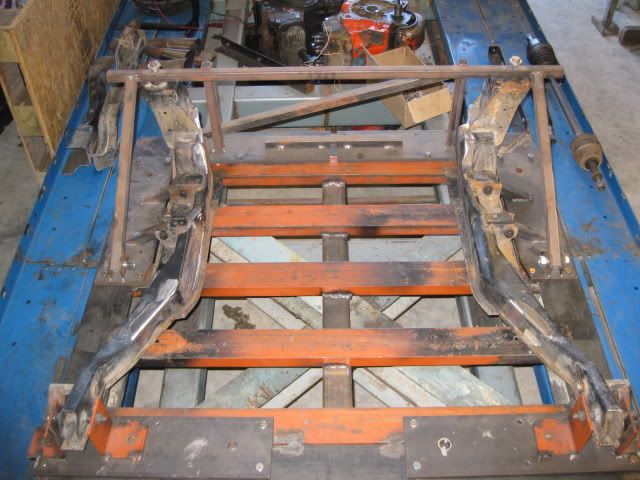
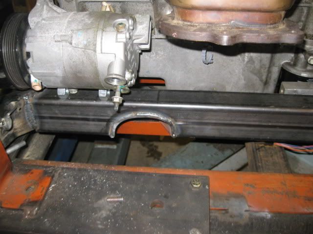
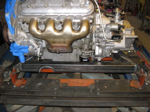
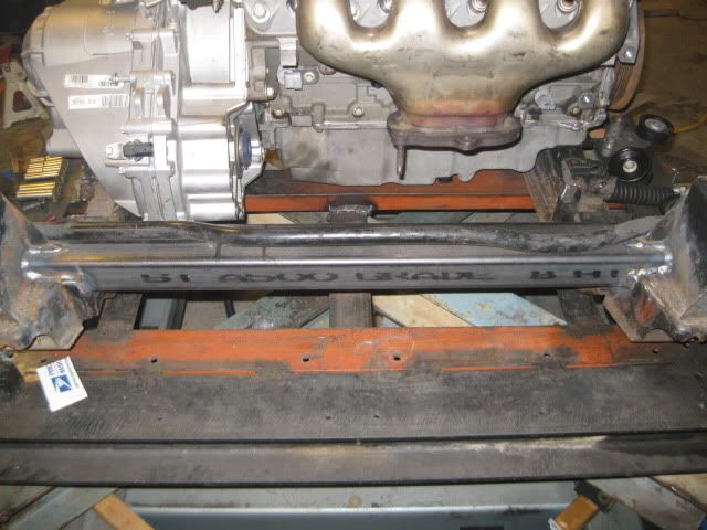
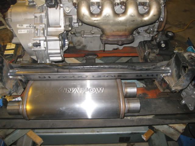
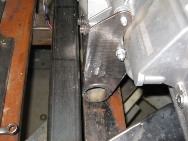
After the test fit, I knew there needed to be some modifications to at least the front cross member, so I took one the 88 cradles and did this to it: Then put it in the 88 cradle fixture and welded in new 2x3x1/8” cross members front and rear. The front one was moved further forward and the rear one was raised to increase room for a wider/thicker muffler.
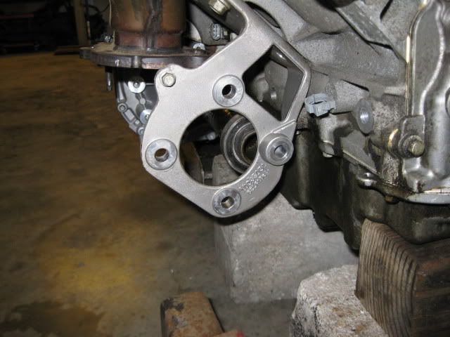
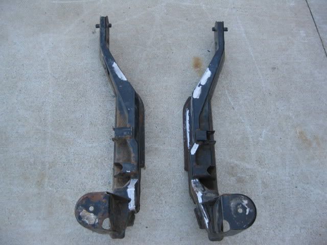
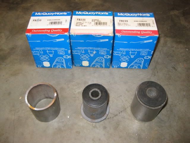
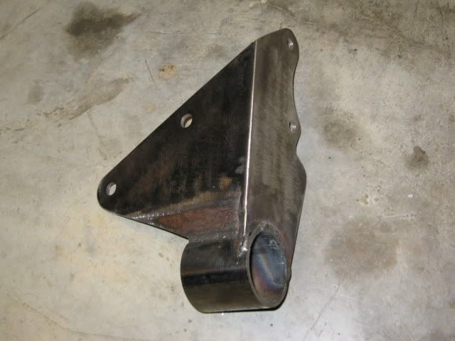
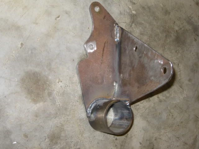
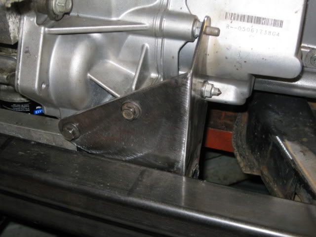
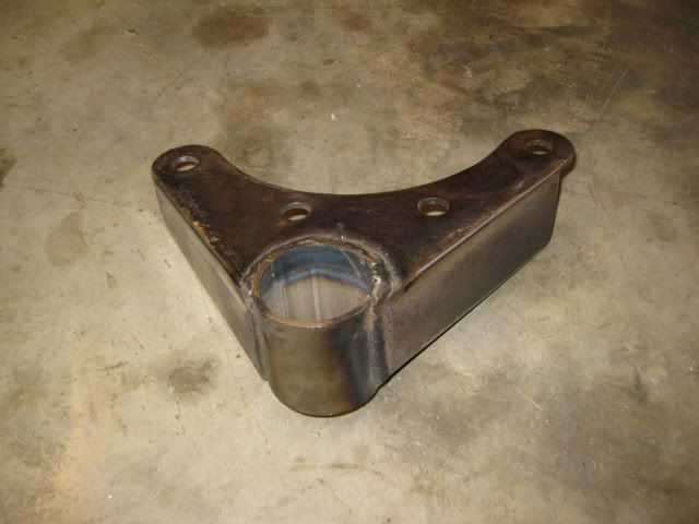
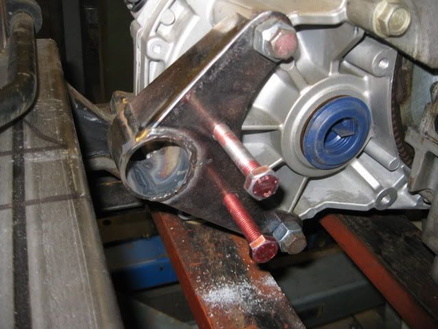
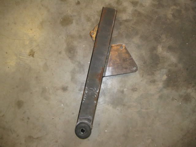
For the mounts, I will be using a 4 corner rubber mount system using the FB235 mounts that can be purchased for 6.99. These mounts will be pressed into a metal sleeve and the sleeve welded to the brackets. Here is the front transmission mount bracket: Here is the rear transmission bracket: After the next test fit, I will fabricate the tabs that will be welded to the cross members to finish up the mounts.
The engine mount brackets are slightly more complicated, but I hope to have them done this weekend .
Here is a shot of the exhaust pipe clearance under the oil pan:
I agree... time for the Construction Zone! I'm keeping this thread in my fav's as I gather ideas for tranny mounts for my Blooz Own project. Nice work Guru.
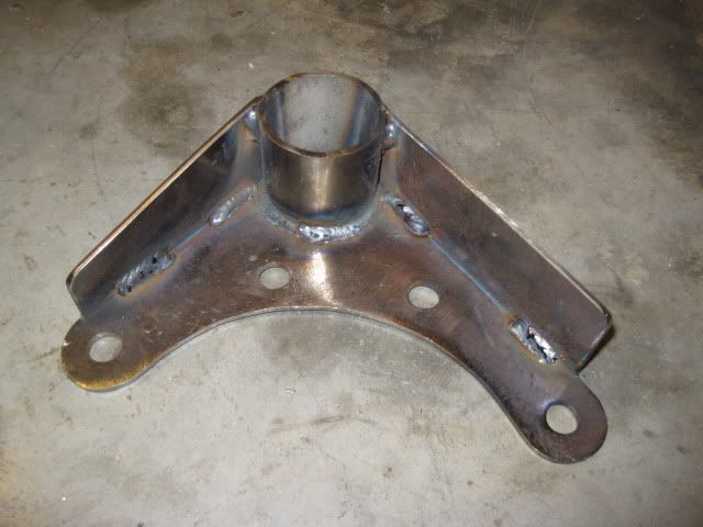
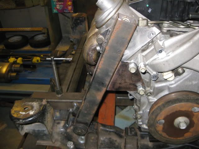
I ran out of time this morning before "quiet time" (nap time for the girls, so no cutting/grinding), so I was not able to finish the tapered contour at the top... but here are a couple work in progress picture of the rear engine mount. Just like the other 2 mounts, 4 bolt holes are used (one at the very top you can not see yet) to spread the load:
On the rear cross member is a locating tool for this mount... it locates the bottom bushing in the same location as the rear transmission mount. Doing this isn't required, but I try to keep the mounts co-linear when ever possible. I also like to position the mounts as far apart as possible to better control any drive train movement without needing any top side supports.
After "quiet time" I should be able to put the finishing touches on this mount.
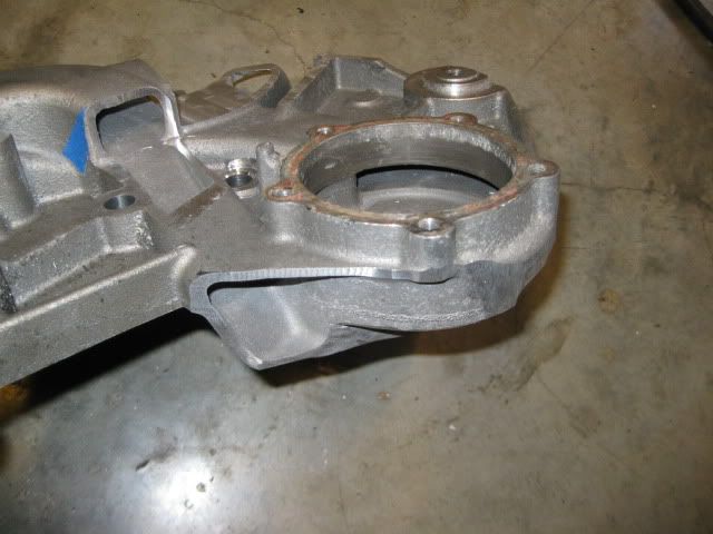
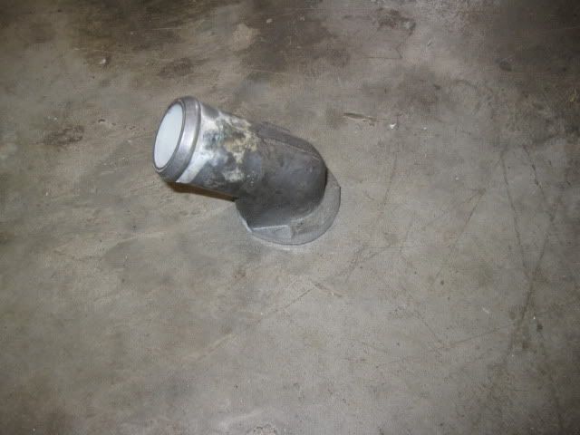
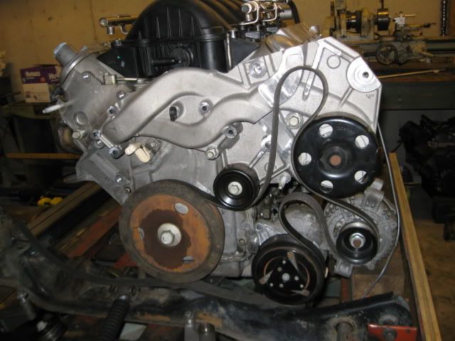
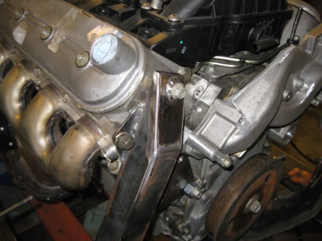
The front engine mount will be integrated with the accessory brackets... which brings me to the water pump. The stock LS4 water pump is compact in that it protrudes very little beyond the LS4 balancer. This helps ensure everything fits within the frame rails, but at an expense. The LS4 coolant fill location hits the stock deck lid spring box and the swaps so far have either moved the box or modified the water pump (or both). I chose to modify the water pump to fix the coolant fill issue, address the location for the alternator and the cluttered collection of hoses at the based of the LS4 water pump. All completed LS4 swaps have either trimmed the passenger frame rail to mount it on the rear of the engine down low (right above the axle) or use WCF reverse cantilevered mount to hang it over the old battery location. I am after a clean and simple design and wanted the alternator out of sight and along side the alternator (like all my other swaps have been). This avoids the frame rail mod and keeps the alternator hidden.
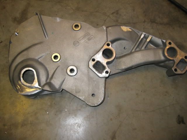
Everything in blue is going away:
Once the majority of it is trimmed:
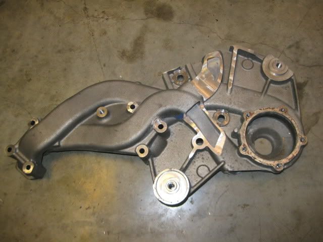
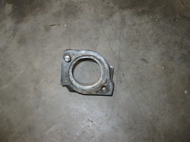
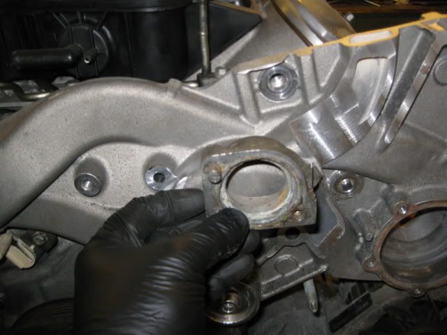
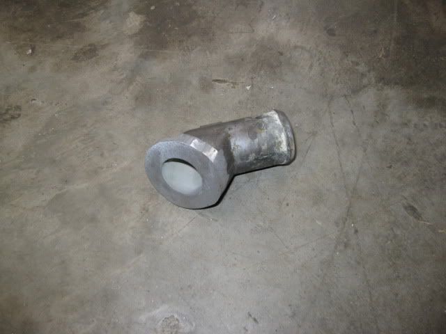
As you look at the pictures above, you can see the outlet for the water pump goes to the top and the portion removed at the bottom was just the passage to the thermostat housing (and the thermostat housing). Before you all freak out, here is my new (chunk of a 4.3 intake manifold) thermostat housing that will be welded to the LS4 water pump housing:
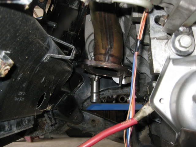
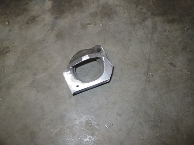
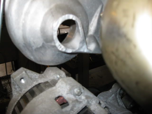
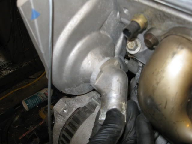
Here is the nipple (another modified thermostat housing) that will be welded on the back side of the water pump for the coolant inlet. I still need to shorten it some to gain more clearance to the exhaust (that is the outer heat shield, not the primary tube):
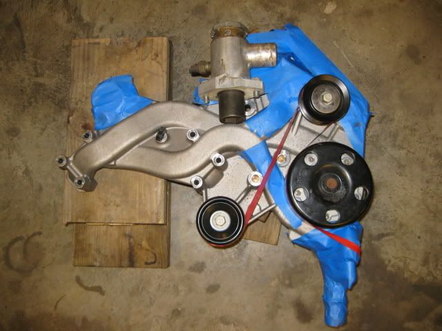
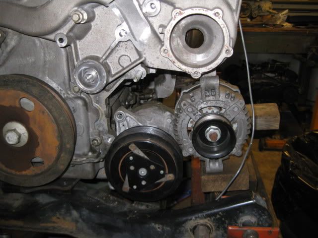
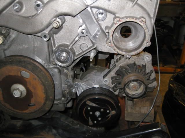
Here is a rough approximation of the belt drive for the accessories: If you look close at this picture you can see a piece of 1/8" wire along side the alternator, the lower portion of this represents the slight indent in the double firewall section that gives just enough room (might move the engine/tranny rearward about 3/8" to gain more clearance when I finalize the mount locations on the cradle.
I was planning to reuse the LS4 alternator and A/C compressor since they came with the engine, but the LS4 alternator is mounted funky with the bottom mount flange mostly inaccessible... the 88 4cyl Fiero alternator fits better and would be easier to mount.
The jury is still out on the LS4 AC compressor. It only has 2 mounting ears so it can not be used to help stabilize the alternator mounting. The 88 4cyl AC compressor has 4 ears and could be used to help stabilize the alternator, but I haven't checked to see if it would fit yet (need to take it off another engine first).
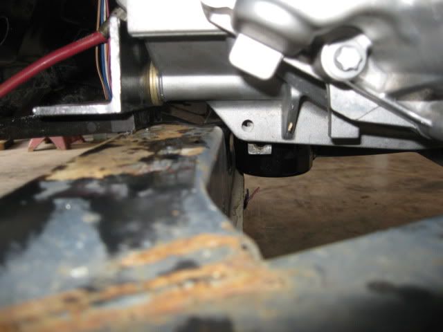
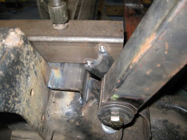
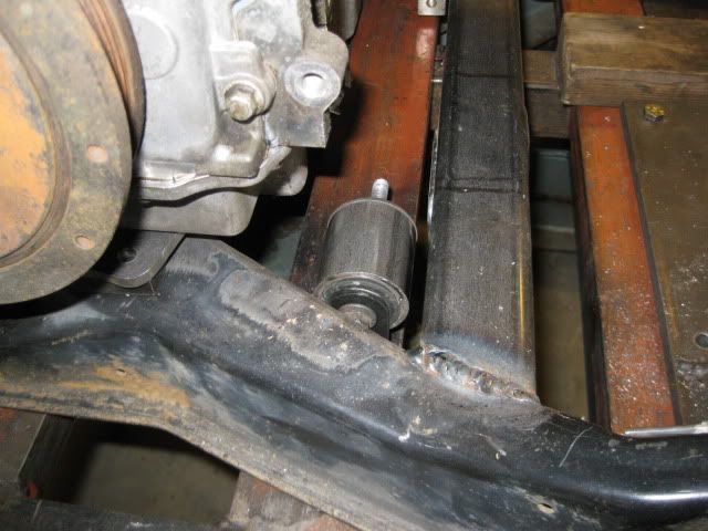
Below whatever I do for the AC and Alternator, there needs to be an engine mount in this general location:
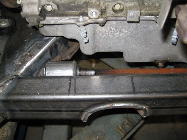
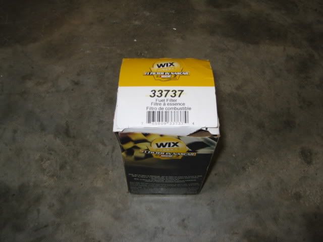
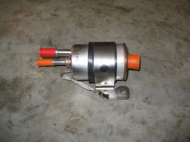
One last bit of info... the LS4 came with a return-less fuel system and I plan to keep it return less. The easiest and probably a cheapest way to accomplish this is with a factory fuel filter/regulator built into 1 for the Corvettes. In my best Mad Max Thunder Dome chant "2 lines enter, 1 line leaves, 2 lines enter, 1 line leaves..." I picked mine up for just over $40 shipped:
[This message has been edited by fieroguru (edited 12-18-2010).]
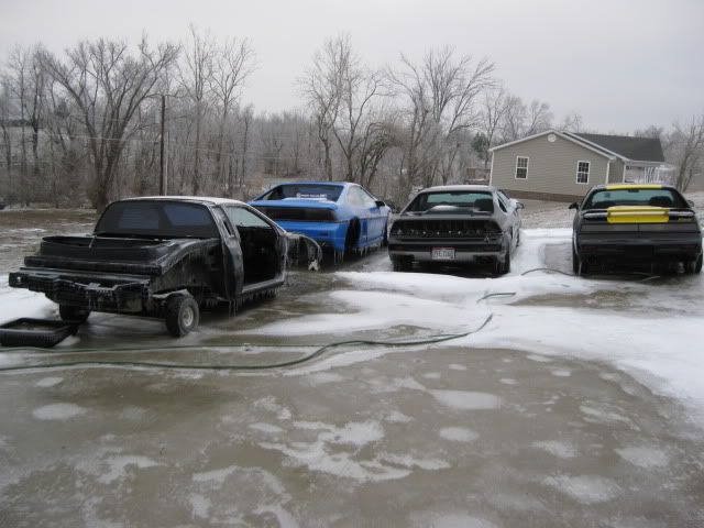
I am waiting for a day above 32 degrees so the mockup chassis can come back inside for another test fit... until then it will just keep the others company:
Sara started cooking the holiday cookies and volunteered to over see quality control, so not much else will happen today.