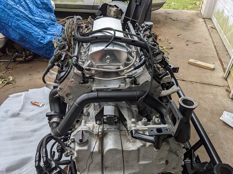
Small update. Mike and I spent this past Sunday marrying the engine wiring harness to the Deutsch connection that will be at the bulkhead/firewall of the engine compartment. We did a point-to-point test with the voltmeter.
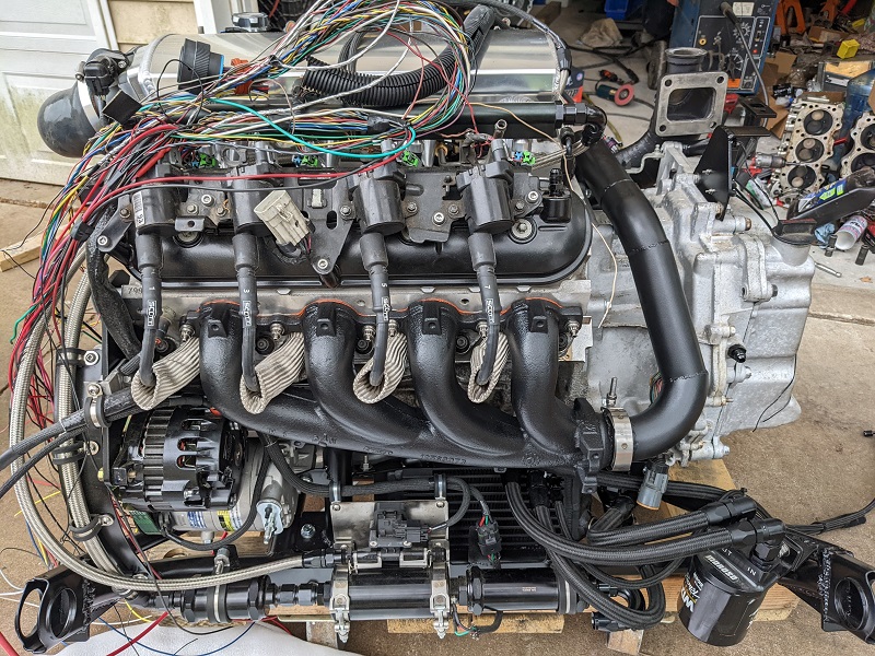
I think there is still a few wires left that we need to do. Besides what he had already done, we finished all the coil pack wires, injector wires, IAC, TPS, MAP. We left off with a sensor that he had to look up info on the sensor itself, because the FAST system had two different wiring configurations, depending on how the sensor functioned (I think he said that sensor could either be a 5v reference or a PWM?)
I also think I have everything ironed out for my axles. I'm going to hold off on details until I have them in my hands and they work, then I'll gladly share details on the company, process, etc. To that end, the company wants us to weld up a mock-up of the axle center shaft (in addition to filling out their paperwork with measurements), and send in the mock up axles, along with one tripod and one CV joint. I suppose they want to make doubly sure a number wasn't misread, or a typo, or whatever, so the mock up axles are a 'verifiable' standard.
Mike was a little annoyed by that news, and said "What if the customer doesn't have someone like me that can weld? Even if it's just a crap weld to hold them together, not everyone has a welder." To which I replied "If someone is calling up and needs custom length axles, the owner probably modified the car enough that they DO have someone like you working on the car."
The fact the axle company is asking you to mock things up after you have given them or haven't given them measurements is an indication they have incompetent staff and lack of understanding to ask you for that info to make your axles. If they don't fit they can't blame nobody but mike! That's the way I see it Vince!
The fact the axle company is asking you to mock things up after you have given them or haven't given them measurements is an indication they have incompetent staff and lack of understanding to ask you for that info to make your axles. If they don't fit they can't blame nobody but mike! That's the way I see it Vince!
It might be more to avoid legal headaches, too. I've continued discussions with another very well known axle shop, and in my last email put down some details and included pictures for reference. When he replied back, he asked "So does your transmission have male stubs? Can you send me pictures of your transmission?"
So, I responded back and politely pointed out I had attached those in the last email, and attached the the relevant pics again. He followed up with additional measurement instructions. Given that there are known math factors here that I supplied them with -- the corvette flanges, which I had also provided measurements of, and the measurement between flanges when they were mounted, and from the transmission case to the wheel hub on both sides -- it adds that it's just as much trepidation and offloading liabilities.
I get it, there are a lot of really incompetent people out there, including buyers! So these guys are just doing a CYA. I don't hold anything against them, and all these extra measurements and precautions between these two (possibly three) companies is going to help make absolutely sure that when I say "I need x", I will get the right thing.
In the end, as long as what I get fits and I get it in the time they quote me, I'm happy to jump through these little hoops. And then once I have a set that is spot on, I can do the "compressed length" measurement and the measurement of the intermediate rod itself, and get extras much easier!
April 2022, Page 16 of build thread This past Saturday we made some progress.
Mike has finished up all of the engine harness wiring. The Deutsch connector I got for the bulkhead doesn't have enough spots for the transmission, so I'll be getting another one for that.
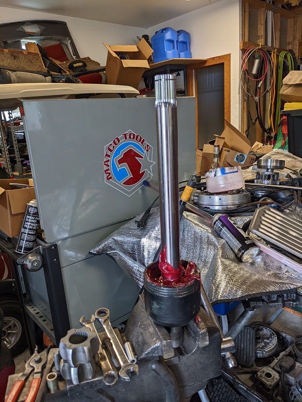
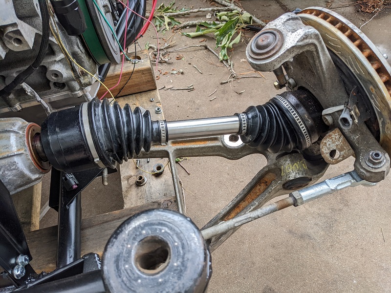
This weekend the priority was getting the axle mockups done. So we used the measurements I had taken for one of the other companies I was working with (who wanted flange-to-flange at neutral, droop and compression). We measured out that flange to flange measurement again and marked the axle shaft then made the cuts. Mike then took off the flanges.
This is where things got fun. The inner flanges were no issue. On one side, it is a tripod setup, so just wiggled out. And the tripod itself was held on the shaft with a basic spring clip (the kind with the eyelets). The other inner side though, was a CV Joint held in with a spring clip. Now the axle with the tripod was an aftermarket Corvette replacement that I had bought -- at least I think it was that side. lol
When taking off the outer flanges, one side popped off the c-clip without issues. The other side fought us. We tried a number of things, and ultimately had to use destructive force. When we got it off, we found that the c-clip had caught the very edge of the teeth just the wrong way, and our force was making the teeth slightly deform, making an indent for the c-clip. Of course we had no way to know this, and even rotating the axle and wiggling the flange before hammering it again didn't make a difference.
The CV Joint in the outer flange does NOT want to come out. It's not held in with any kind of clip. Talking with the axle folks, they said we could use a hammer and screwdriver to push the cage far enough away to pop out a ball, then rinse and repeat until the cage came loose, and the star would come out too.
Of course, GM does (did?) sell the outer flange ( part #88952504 ), and even that is a "kit", with the cv joint installed. When it can be found, it's three times the cost of entire replacement axles. Similar to the inner flange (88952505 ) and the center shaft (28 spline, 10311201 ). Even finding those part numbers were a pain in the ass.
I've yet to find the part numbers for the actual CV joints (or the tripods) that the axles use.
I have another corvette axle on the shelf, so if we can take that one apart without any headaches, we'll use that outer flange. Mike would also like to make the inner flanges match as far as mechanisms, and he'd prefer the CV joint versus the tripod, so here's hoping the inner is the cv joint on this one.
After Mike welded up the mock up axles, we then took the drive train off the cradle and split the engine from the transmission. This week Mike is planning on putting in time to get the final welding done on the cradle, and drop it off at the powder coater by Friday.
Before we had taken the flanges off the mocked up axles, I wanted to pop them in the drive train and check things out, but Mike was confident in our measurements. I explained I was more worried that I could have fat-fingered one of the measurements when I was putting them into my phone. Fingers crossed that I didn't make any mistakes there.
Today I shipped off the mock up axles. They should get them by Friday. I'll get into details on how it goes once I get them back. If they fulfill their estimated timeline, I should be getting my axles about the same time I get my exhaust back from Jet Hot (sometime in the last week of the month or First week of May).
[This message has been edited by Trinten (edited 03-26-2023).]
When we took the original set of measurements (flange to flange), had the wheel bolted on, and had done full compression, droop and ride height. So we knew the extremes of travel plus the center point. Mike used those measurements to work out what should the appropriate length with a safety margin for the reason you stated, hitting a nasty pothole and making sure the cv joints have appropriate travel space inside the flanges.
As mentioned, my major concern with stuff like this is if I did a good job at correctly punching the numbers in on my phone. I can ten-key on a keyboard at rapid fire pace and high accuracy. The phone (and it's propensity to autocorrect) is a little more challenging.
When the axles get back, if there is an issue with the extreme positions, we can still use them to trailer the car to the dyno and possibly to the track while I get another set made.
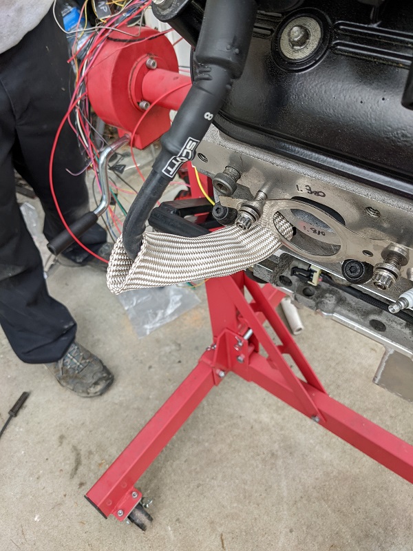
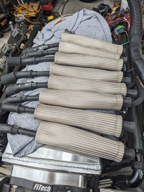
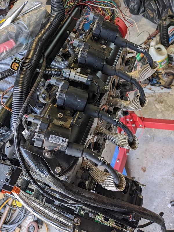
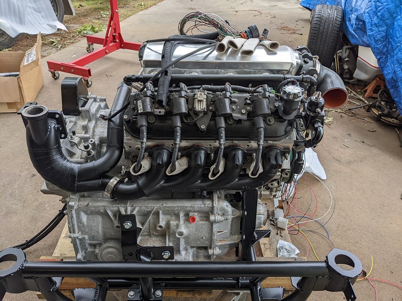
We built the spark plug wires. They're all 10" long. The amount of wire that came with the kit will let us get at least an entire second set if necessary, I would just need to get the crimps.
Mike was happy with the quality of the fiberglass sheathing, the EFI wind wire, insulation, etc. The fiberglass boot protectors seem to be really good quality, too. Mike mounted up a spare 6.0 header (same as the one that we modified) to make sure the spark plug wire would clear everything, and not kink the boot protector.
We did test each wire after it was made. Mike pointed out that his voltmeter for his day job was different than what an electrical engineer would have, it only has one Ohm setting. He used a Fluke 79 Series II voltmeter.
My wires do have a higher resistance than Will's Magnecore set by quite a bit. So even though they don't have a 10mm wire, it might be something to keep in mind for the future.
We also tested an uncrimped wire to get an idea of resistance per foot, it worked out to be 29.05 / foot.
We also adjusted the stainless steel tube that runs to the underside of the intake for vacuum. That required us removing the intake, which was an exercise in disassembly/assembly of everything in that area.
While the intake was off, we did a detailed check of all the cylinders using his bore scope while I rotated the crank. No issues, though there was a dead bee in one. It must have flown in there one of the times we had the intake off, and then couldn't escape.
Mike also connected the main feed wire and solenoid wire to the starter, and got that sleeved. I have more of the ultra-high time secondary layer of wire protection stuff on it's way (J&T Fire Flex).
Last week he finished getting the cradle welded up, and it's at the powder coaters. It's expected to be back sometime after the 25.
The axle shop received my mock up axles and paperwork on Friday. If I don't hear from them tomorrow, I'll call them on Tuesday. The guy I was emailing with said he would call me once they got said materials.
The last week of this month, and the first few months of May are going to be hectic, we'll have the cradle back, should have the exhaust back from Jet Hot, and by mid-May should have my axle shafts.
Though time is tight, Mike still thinks we can get enough done to be able to drive the car up to Carlisle this year. He wanted to drive up his 3800 swapped Fiero -- but the swap isn't done. lol. His swap is all mounted on the cradle, nothing else (wiring for example) still needs to be done. Some things are just taking longer than anticipated for my build, unfortunately.
[This message has been edited by Trinten (edited 03-26-2023).]
This past weekend Mike did a double check on the transmission. we learned from Brandon Furches that the 2-3 shift in the 4T80 is a long/slow shift, and not good for longevity when you're beating it up on the track. Thankfully there is an easy way to fix it!
I think I mentioned earlier that Dave at TripleEdge wasn't sure if he had done any magic with the 2-3 shift. The upside is he had. It's supposed to have one spring under that piston, it had a dual spring in there. Mike was also happy that it was very easy to get to that component, we didn't have to tear down the whole transmission.
The cradle and cradle components came back from powder coating, so we started mounting things back onto it. Transmission and fuel system.
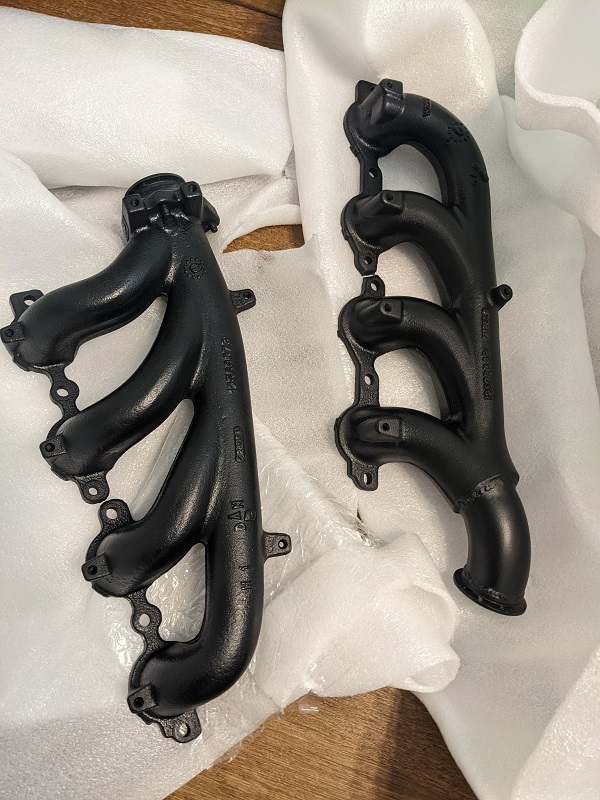
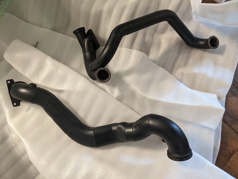
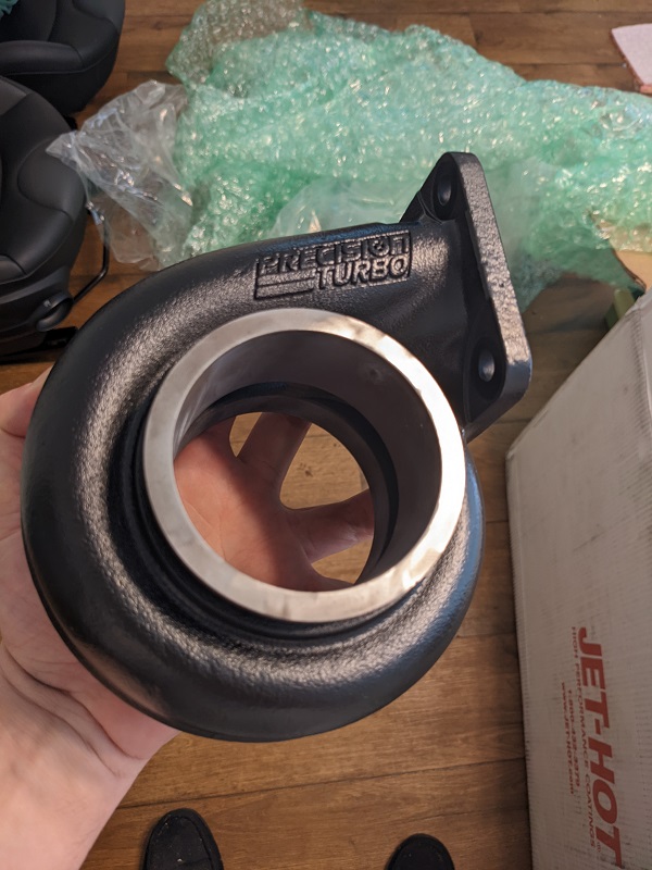
And today the turbo housing and exhaust components came back from Jet hot, with the spiffy 2500 degree coating applied!
Tomorrow the half shafts for the axles should be showing up. If Mike doesn't have the time/interest in putting the axles together during the week (I wouldn't blame him), then we'll do that this weekend, along with mounting the engine back on the cradle, start prepping the engine bay, and possible replacing the last few suspension components in the back.
Besides the engine bay mods and prep, we still have a fair amount of wiring to do. Then there's wheel alignment, tuning, shakedown...
There is a big Grand National thing in Kentucky this month. So the weekend of the 14th there won't be anything done. And the last weekend of the month is our mutual friends birthday party. So I know I'll be at the party on Saturday. Not sure if Mike will or not.
Mike is going to start putting Saturdays and Sundays into my car. He really wants to try to push to get it to a point where we can put miles on it and drive it up to Carlisle (end of June). I suspect we'll be trailering it up there again this year, but will hopefully be moving under it's own powering onto and off of the trailer.
[This message has been edited by Trinten (edited 03-26-2023).]
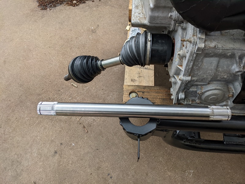
Dutchman axles is the company I worked with. Travis was the person there that handled my order. He was really responsive by email, and we had good communication.
The material they used for my axles is called Hy-Tuff alloy, which is stronger than 4340, but not as much as 300M.
And they had it in stock, versus another place that used the same material but said it was 8-10 weeks, at best.
Dutchman originally quoted 3-5 weeks after they spec-sheeted the axles. They beat that by leaps and bounds. They had them packed up and shipped out to me in LESS THAN A WEEK!
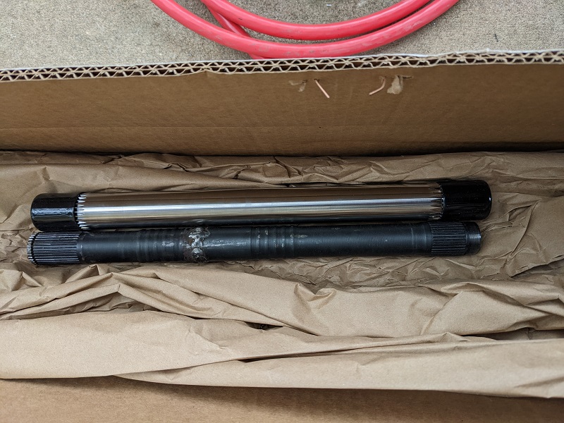
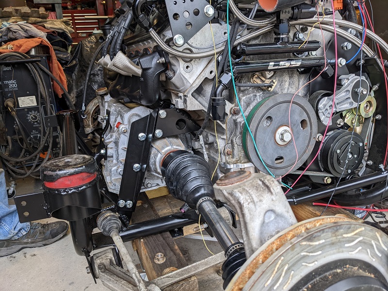
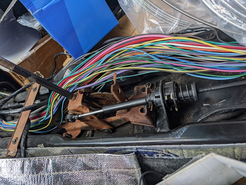
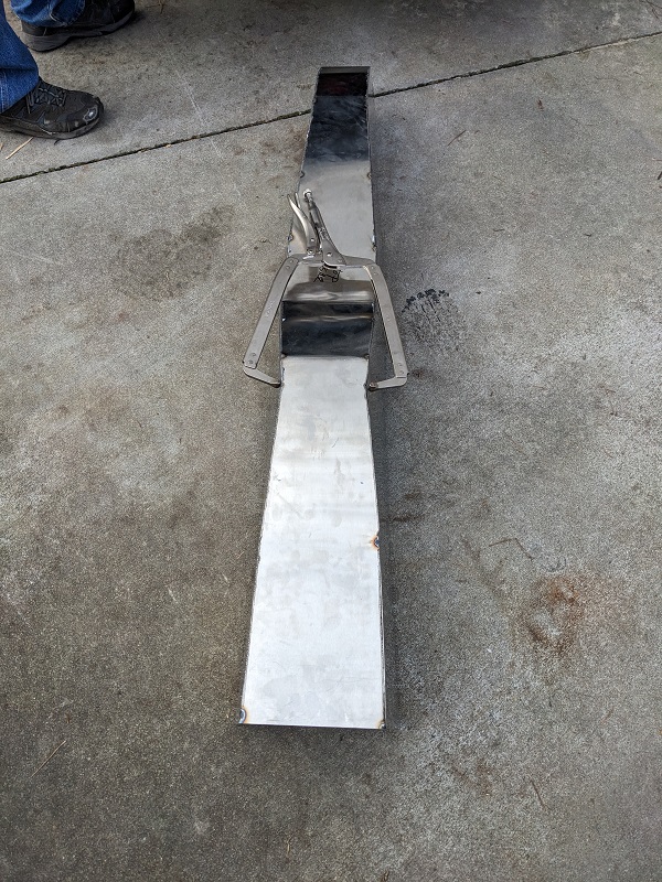
Here is one of the half shafts next to the mockup.
The only drawback is that Dutchman doesn't make complete cv joints, so Mike and I had to disassemble the Corvette axles, and assemble the joints/flanges on the new half shafts. It went smoothly.
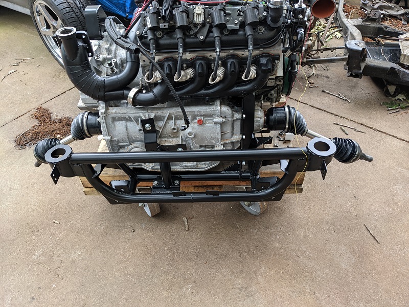
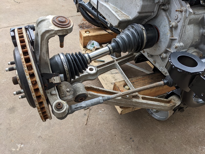
And once the axles were ready, we went about putting the knuckles on and replacing suspension components. The outter tie rod ends on the 'stabilizer bars' were shot on both sides. I had one complete unit that was in good shape, and I have managed to find 4 of the actual outer ends (which are not the same as the ones in the front), so used one of those on the other side.
We also replaced a balljoint. It was made by ProForge, and it's greasable, which is nice. What wasn't nice is that it uses it's own nut, in a different thread pitch. So in the future if I have to take that apart, I have to make sure to keep all that stuff straight.
Mike learned that some of the Corvette guys were running into issues with tearing out the inner tie rod end in the back when running big power and slicks. So he had made sure that mounting point was reinforced.
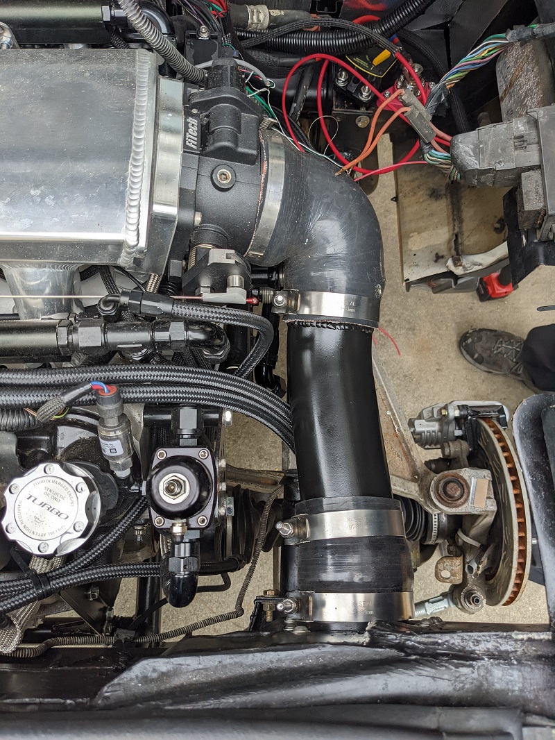
We put on the exhaust parts that came back from Jet Hot. (except the downpipe, that's not mounted yet).
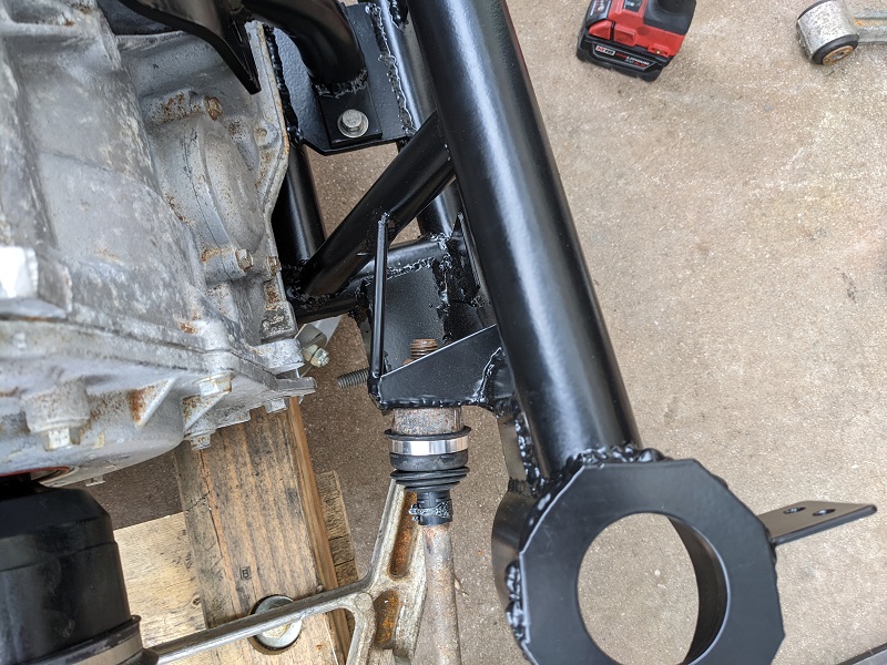
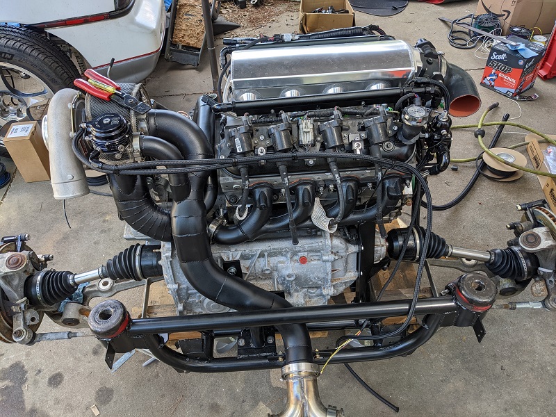
And here is just a generic shot of some of the bracing that supports the transmission and keeps it from wrenching itself around under power.
[This message has been edited by Trinten (edited 03-26-2023).]
Hey Vince, what's supporting the weight of the turbocharger? Is Mike doing any bracketry to prevent it to crack the exhaust once it gets hot and brittle and the bouncing of driving takes a toll on it? Haven't seen any corrugated or "expanding" part to make up for the heat expansion and growth on the exhaust.
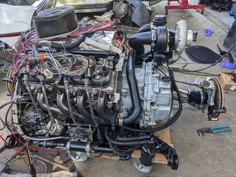
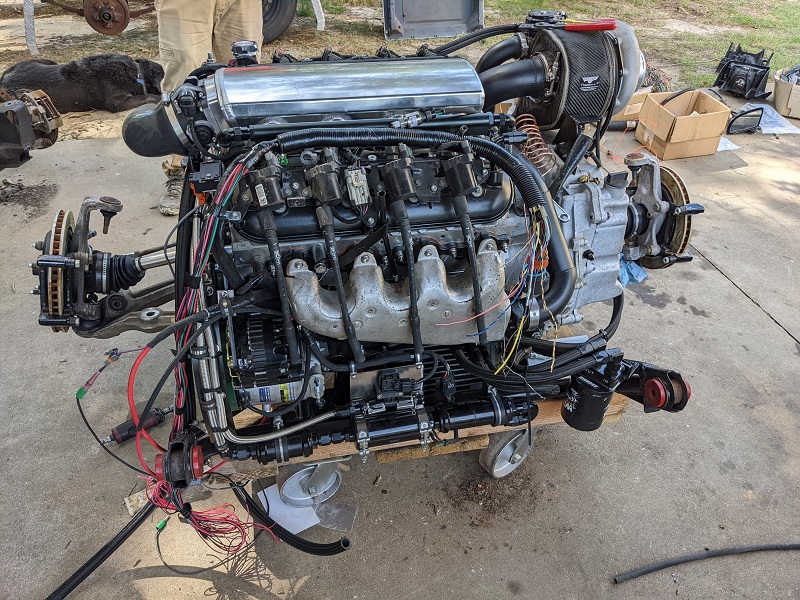
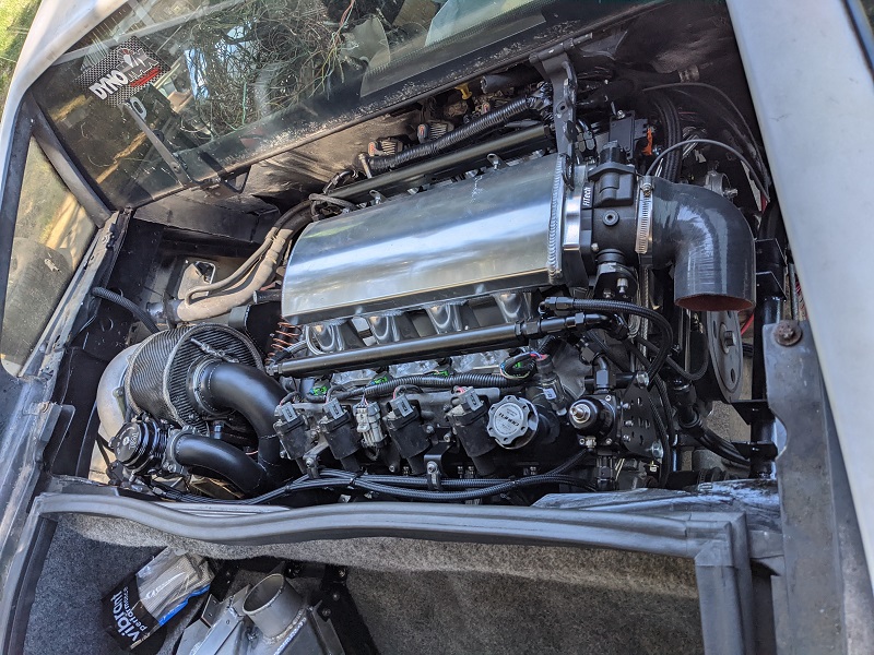
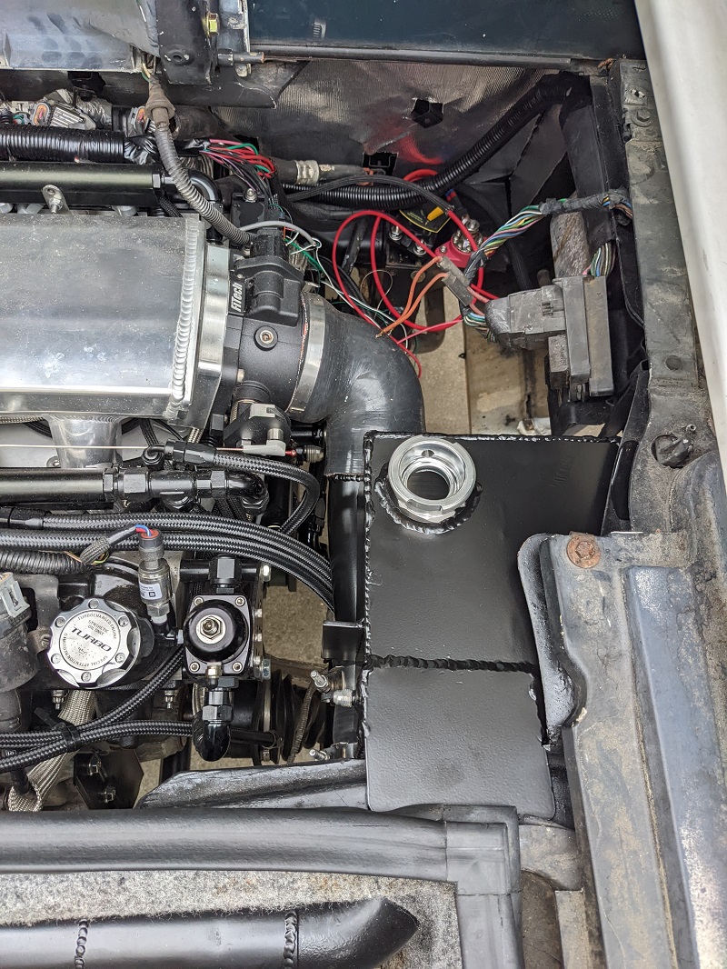
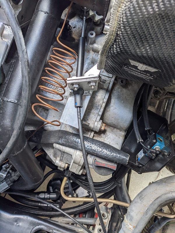
In an earlier picture you can see the 'perch' for the turbo, which also has the drain tube (the black thing sitting near the top of the transmission's valve body cover):
When we were doing the assembly today he was explaining that he had put it together so some parts were under a 'spring load', and when they heat up, it'll move to a relaxed position. If he had it a neutral position to start, the heat would make it expand in a more unpredictable way.
He's done the same method on his streetable track car, and hasn't had any issues with anything cracking from thermal expansion. I had asked him about those 'flexible joints' last year when we started mapping out the exhaust, and he gave me his various reasons for not liking or using them.
So we'll see how it goes. If anything fails, we'll improve it.
The last few weeks have been something of a blur with work and personal life. There has been progress on the car, though some things aren't finished, and I'd rather try to wait till they are done and post about it all together (like cleaning up the bulkhead and getting on FieroGuru's cool decklid hinges he put on my last Fiero).
So for today, we'll just touch up on some quick stuff.
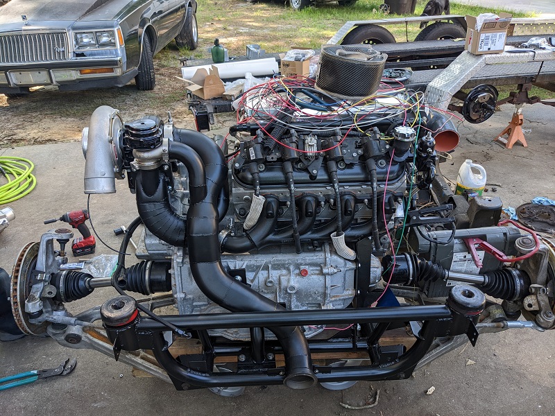
The turbo and waste gate are mounted to the exhaust setup!
And I picked up some very well reviewed and rated (and probably a little gimicky) volcanic super-spiffy turbo blankets. And they had one for the waste gate. So I got it. Because why not?
When Mike was mounting the waste gate, he's now taking a closer look at it (versus before when they was just taking it out of the box for measurements/placing to fabricate) and he says to me "You bought a water cooled waste gate?"
To which I reply with a humorously indignant tone "No. You bought a water cooled waste gate. Remember the original TIAL one I bought was too big, so you bought this one."
He conceded the point and says it won't be an issue to plumb in using the "Steam vents", he had just never seen the point of water cooled waste gates and in most cases when normal waste gates have failed (outside of age/use) it was due to config/install issues. So I have a few more -4 AN fittings and hose coming so he can do that.
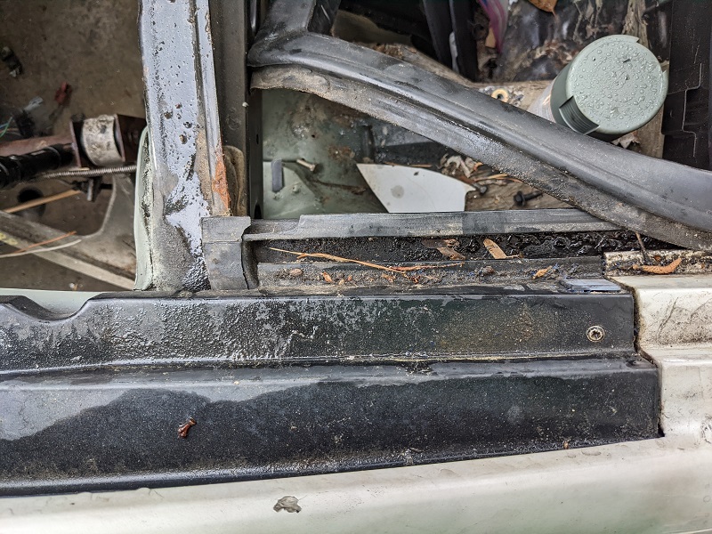
As mentioned I'll do a focused post on the engine bay prep later, but in related news, we discovered both of the trunks plastic rain-guiding "d-plates" are cracked up pretty badly. One side was exacerbated by Mike when he was getting out of the engine bay and put his hand there (on top of the weatherstrip), and we heard the crack.
So I'm trying to hunt down undamaged ones. And hopefully someone is making repops out of better materials.
Oh, for any eagle eyed viewers, yes the spark plugs are back out, hence the wires dangling there. Mike wanted to spin the engine while it was out of the car to get the oil to start moving through and make sure there were no leaks to address. Much easier to fix before we put it in.
This did lead to him having an 'ah-ha' moment, going back to Brandon Furches videos on putting the 4T80 with the LS4, and one part of the transmission that he ground out a fairly deep pocket. Mike had done a smaller pocket there, not realizing what it was for (either Brandon wasn't explicit, or just the lapse in time from between when they were originally married together, and we got the spiffy Moroso oil pan and starter. So the bendix can't engage with the flexplate, it smacks the transmission.
Mike isn't comfortable with having his cherry picker holding up everything (engine, trans, cradle, suspension), since it would be at it's furthest/weakest point on the picker and he'd be under it. So this will be addressed once the cradle is in the car and he can get to that area without my cradle-skid obstructing him.
[This message has been edited by Trinten (edited 03-26-2023).]
And I picked up some very well reviewed and rated (and probably a little gimicky) volcanic super-spiffy turbo blankets. And they had one for the waste gate. So I got it. Because why not?
Is that really where it goes on the wastegate, though?
Honestly... I don't know. In hindsight it makes sense that it would be wrapped around the bottom. I did that part. The "directions" had no pictures and just said "use wire to secure blanket, watch for pointy metal bits!"
I thought it went on that way because the blanket has a 'badge' on there for the company, and placed in this way it's orientated right. I figured they wouldn't set it up to be upside down.
I'll fix that this weekend. Thanks for the catch Will (I'm sure by now Mike has seen it and will make a joke).
[This message has been edited by Trinten (edited 06-03-2022).]
Shemdogg, thank you! Mike put a lot of work into it. He wanted something functional, servicable (as much as possible), and durable. I wanted to make sure heat was minimized, and things looked good without interfering with the first three priorities.
Not without a few hiccups, of course. The first is I need to order another set of cradle bolts. The ones we used work but we know they aren't (all) the right ones, because the size of the hex heads changed from side to side.
Also, somewhere along the way we lost the metal bushings that go inside the poly of the bushings in the front. mike had some others laying around that we used as temps, but they are not the right length (a little too short).
If anyone knows the specifics (material, wall thickness, I.D., exact length), I can hopefully get another set from McMaster Carr or something. Worst case, I buy another set of poly bushings, and put the new poly on the shelf for now.
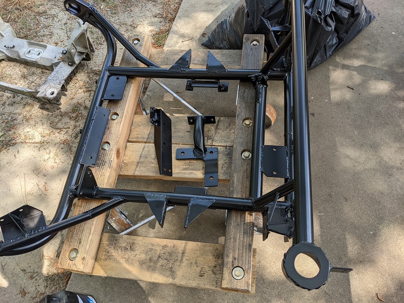
Mike still has a little welding to do on removable frame rails, where the upper control arms bolt on. For now we paint-bombed it just so it looks better than it did last year at Carlisle. We'll wire-wheel off the paint, finish the welding, and the powdercoating company will meda-blast it before the coating goes on.
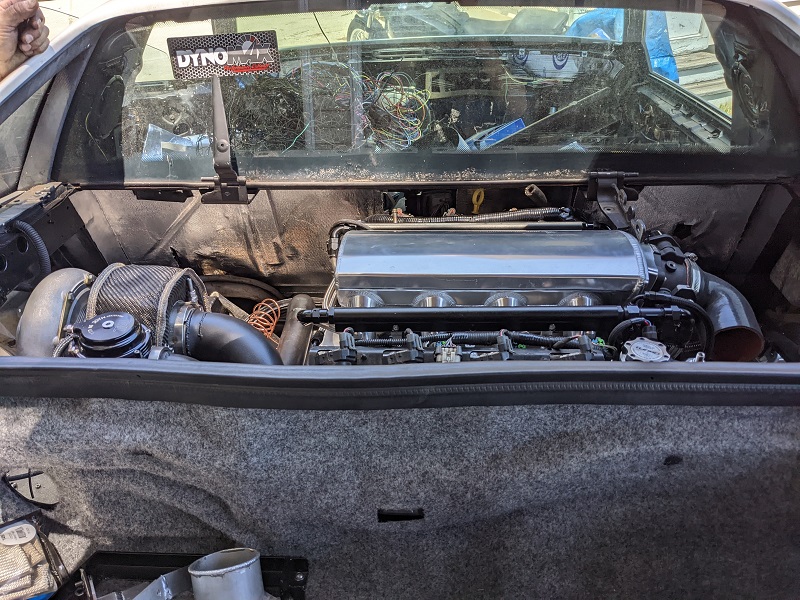
Here it is, ready to go in!
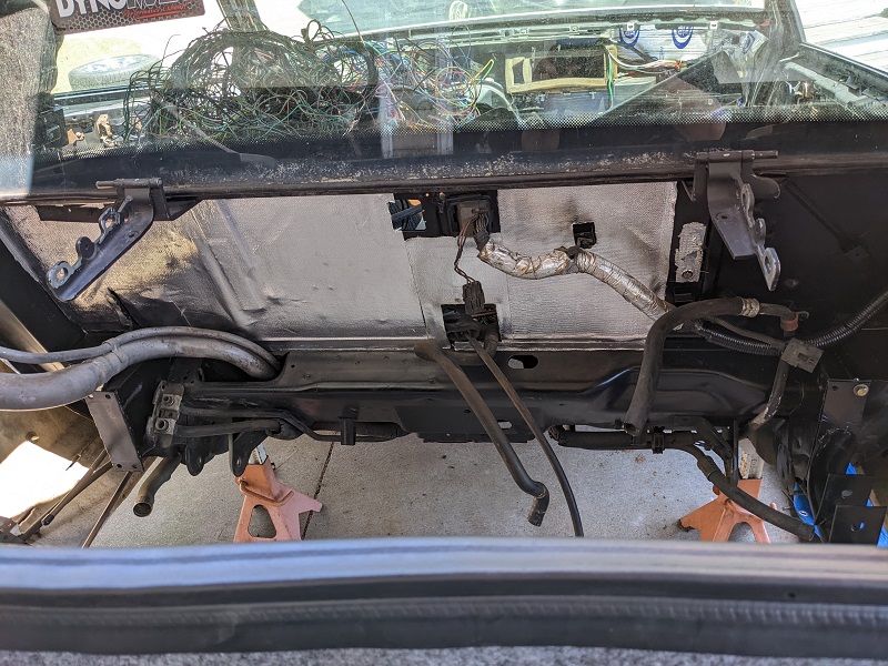
We had to finish installing FieroGuru's hood hinge on the passenger side, and then we finished putting in the Thermo-Tec material on the bulkhead. I got a picture before we finished with the hinge and material, but we were in such a hurry to get the engine in today (Mike had other obligations), I didn't take a picture afterwards.
As Will called out, I had the wastegate blanket on wrong. when I got there I asked Mike for the "weird locking tool to clip wires while spinning them" and he says "what for?" and I say "So I can fix this turbo blanket." "I was wondering when you were going to figure that out." "I didn't, Will told me." he laughed. We fixed it.
Putting the body back down on the engine was very slow going, a lot to watch, as as the body moved down in an arc, we would need to stop and wiggle my skid around a bit to make sure things stayed aligned and didn't hit.
Thankfully, the only thing we had to do was unscrew the AN lines that run coolant to the wastegate. Mike has a solution, I need to reach out to Tial and see if they make a 90 degree fitting for that. The part that screws into the body of the wastegate appears to be proprietary.
We also knew the oil dipstick was going to be an issue. I need to look through FieroGuru's thread to see how he dealt with this. Where it is now, it is literally unusable. We knew this could happen.
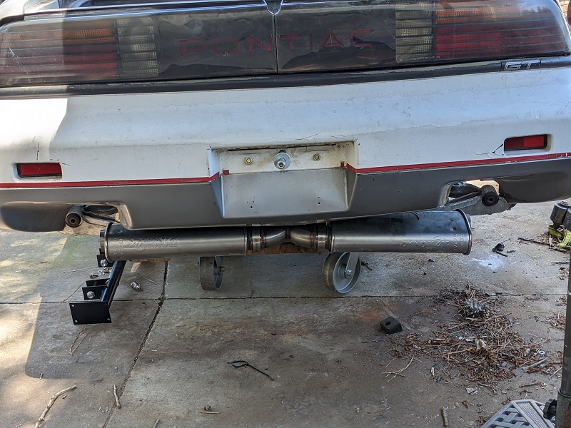
Lastly, the mufflers are visible under the car from just a few feet back. We knew this would be a case, too. The back of the car is still up, the car is resting on the engine skid. The nice part with the v-band setup is that if I don't like these mufflers, popping them off, getting some new bands, new mufflers, Mike does some welding, and they are back on!
With the "y" pipe they are out a little further to the sides than we hoped, Mike said he can still do up some nice tips for them.
Unfortunately it won't be running for Carlisle, we still have hours of wiring to do, need to finish running hoses (and fabricating connections for them in places). Plus gas tank fabrication.
Eagle eyed people may notice the spark plugs aren't in right now. Mike wants to spin the engine by just the starter to cycle the oil through. Having the plugs out will make it less stress on the starter (effectively no compression). It will also let us get an idea of how tough it may be to change plugs in the future.
We aren't doing it out of the car because we need to modify a pocket so the starter bendix engages the flywheel, and the cradle skid is preventing that.
[This message has been edited by Trinten (edited 03-26-2023).]
Originally posted by Trinten: We also knew the oil dipstick was going to be an issue. I need to look through Fiero-Guru's thread to see how he dealt with this. Where it is now, it is literally unusable. We knew this could happen.
Looking good Vince!
Stock routing:
Cut the stock bracket/tab off, rotate the stock dipstick to the driver side (some slight bending required). Once it is in position, modify the old bracket/tab for the new location and tack weld it into place.
Thank you! And thank you for replying back to my email so expeditiously. As always, I am grateful your willingness to help and completeness of information. You will never need to pay for a meal or a drink if I'm around.
So the good news, Mike and I are still going to be at Carlisle!
The bad news, the car won't be moving under it's own power yet. Mike had some work obligations this past weekend, and is unavailable this upcoming Saturday as well. That leaves us with just the last Sunday before Carlisle. We'll likely focus on the few easy things, some hoses and other quasi-cosmetic things that won't need to be undone when we continue the work.
Even if we hadn't lost those days, it's not likely it would be under it's own power. We still needed to finish wiring up Deutsch connectors in the front (and that is surprisingly time consuming), a few hoses, etc.
Trying to get last minute things buttoned up before Carlisle this week. Putting in correct hardware, instead of placeholder stuff (there's still some placeholder stuff), connecting as many lines as possible, etc.
Mike was busy last week and yesterday, so today was just all that stuff. Which meant hunting through boxes for the specific things we needed. Mike cooked up a clamp on adapter for the Fiero coolant lines, so we didn't have to modify them (more). Brakes were put back on, and (most) of the clips and such for the brake hard lines were re-attached.
We ran power to the starter to spin the engine (no spark plugs were in it, so no compression) just to get oil to circulate. Cautious to not burn out the starter, we would do this for about 15 seconds or so at a time, then let it rest for a while, rinse and repeat. No compression also meant less stress on the starter. We heard the tone change as all the air pushed out of the system though the breather, and oil was just circling around.
The only 'leak' was that the oil filter (of all things!) was not securely screwed in place. 1.5 turns later, and that 'leak' was gone!
We then went about to put the spark plugs in... yeahhhh. About that. The rear set weren't an issue, I was able to get all four started and finger tight with just my hand.
The front set were not able to get started from underneath (my own fault, it's from the exhaust manifolds stock bolt-on heat shield). Also from the top wasn't possible because of the stock coil pack setup. So we removed that coil pack, which was fairly difficult. We also had to pop out the stock LS4 dipstick which was in the way (with the angles/room we had to work with). We knew the stock dipstick/tube was going to be an issue anyway, so it's no big issue that we worked it free for now.
If we stick with the stock coil packs, we'll secure it using just the bolts that were easy to get to. I had the idea of seeing if there's some sort of "quick disconnect" stud-based setup. So I'll have to do some searching on that later.
With the coil pack rack out of the way, we were able to get the spark plugs in from the top without much trouble. I talked to Mike about considering doing a remote coil setup like FieroGuru has done, he said he'd think about it. It would mean making or buying another set of spark plug wires, but really, a small expense in the grand scheme of things if we go that route.
I know it's been a while since I've done a substantive update. What we've been working on hasn't really provided a lot of "photo opportunities", though I realized today I should probably document things for my own memory, if nothing else.
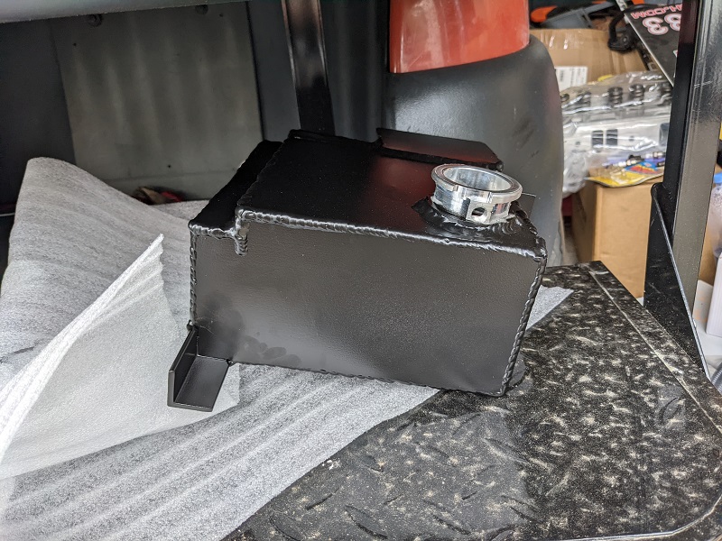
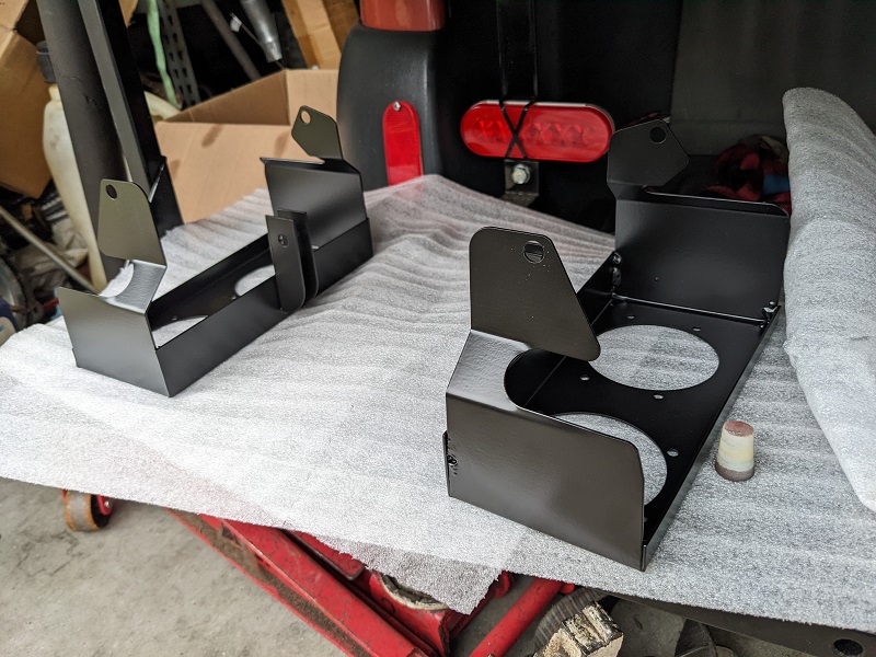
We're waiting for some things to come back from powder coating, and realized we missed a few things that should have gone out with that batch. Included in that are the headlight buckets for the dual 60mm Hella setup, as well as the surge tank. I've already forgotten what else was in that batch... (see why I thought I should post?)
So when that gets back, there will be pics.
The surge tank had to go through a few revisions, because we needed to preserve room for the Spal fan that will be under the passenger side decklid vent, pushing hot air up (out) of the engine compartment. Mike finished mounting the oil catch can. When I have the other pics, I'll post up pictures of that.
Throttle linkage is done, we did have to use a barrel-style clamp to extend the cable, which Mike dislikes because it makes it 'obvious' that it doesn't belong. He's also not thrilled with the Lokar connector to the throttle body, it's made of plastic. So I might need to find someone who has or can make a metal version of it.
Shift cable is connected and working (if I talked about this before, I apologize). It had to be installed backwards, which also meant Mike had to modify the shifter assembly to change-and-move the bracket that the cable secures into, so the adjustable portion could be used if needed. We also had to flip the transmission lever 180 degrees so it worked as intended (front wheel drive transmission in back of the car, things were shifting "the wrong direction", if that makes sense. Moving the shifter towards park, would shift the transmission away from park).
Right now Mike is busy getting sensors in place and finishing securing/clamping tubes and hoses. He also started his plan for the main positive power cable. He wanted to run it right along the rocker panel area, using angle aluminum to make a bracket and shield that would bolt on by replacing the rocker panel plastic rivets with nuts/bolts, and p-clamps to hold the cable in place. It didn't quite work out, so his next idea is to take the rocker panel off, and "hide" the cable in that cavity, and rework the bracket setup.
Once all of the hoses and tubing are finished up, we'll do leak tests (where possible without a running engine) and then he's going to be focused on wiring for the engine, transmission and controller.
My task this week is to look at the wiring diagrams from FAST for the transmission controller and make sure I have spools of all the right colors/stripes of wire. If I'm missing any, I'll be ordering more spools... lol
[This message has been edited by Trinten (edited 03-26-2023).]
There's actually been quite a bit, though not a lot of it is photogenic, mostly Mike putting on wire terminals. I do have some pictures though!
The headlight buckets, surge tank, and last section of intake tube all powder coated.
We also mocked up then mounted the surge tank. The picture I took was during the mockup, for those eagle eyes that notice the clamp missing from the intake.
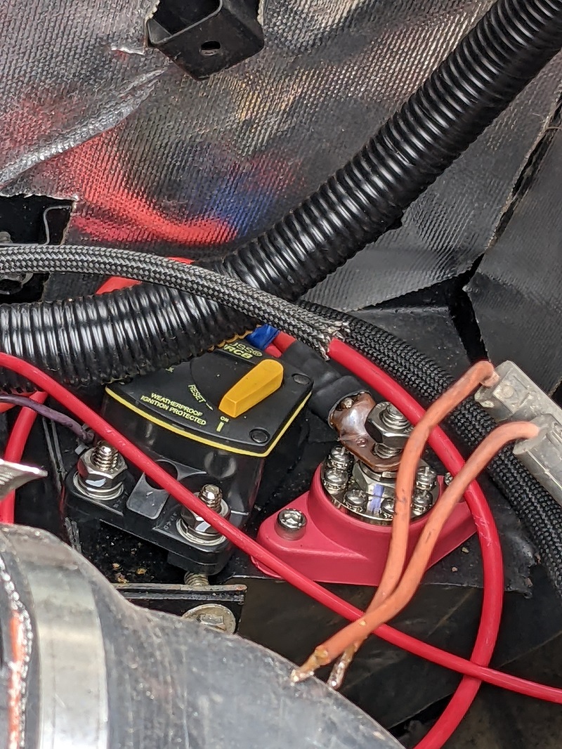
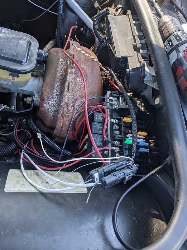
I bought a power distribution block and a UL listed 100A waterproof breaker. They will be mounted in that little spot. The block is already mounted in place. The breaker will go next to it.
After some checking, we are currently planning on running the main power cable through the cabin.I think Mike is going to use the (currently capped) hole that the clutch went through, then over to behind the center console, and up from there with all the other wiring. I have no idea if having that giant power supply line is going to kick off any EM Noise, so I'm going to ask Mike to to put RF suppression wrap around it. I suspect there will be eye rolling. Maybe not.
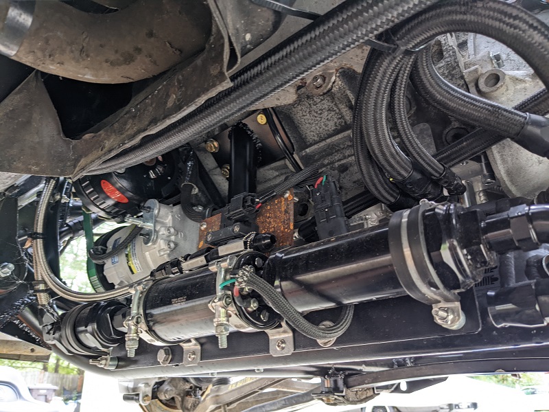
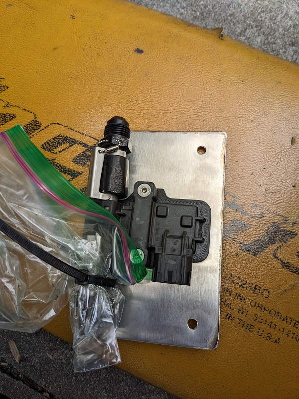
I was under the car to put on the torque converter bolts (ARP of course), and just thought everything looked so awesome, I took a picture. There's only one thing I realized we didn't powder coat - the plate that the flex fuel sensor is mounted to. So I'll have to get that off and just hit it with some VHT paint or something.
Mike also needed some additional stock wiring stuff, which CowsPatoot was kind enough to send over.
He had me get some electrical bulkhead connectors, and more terminals for the heavy gauge positive and negative cable I bought, that's going to be there before this weekend.
So right now, it's lots, and lots, and lots of wiring. This weekend I'll probably mess around and (somewhat pointlessly as they are working okay) rebuild the headlight motors with the kits I bought from Rodney. I got the kits that have the new bushings and the aluminum gears. Just gives me something to do while I'm hanging out. ... damn. I bought those kits a while ago. I need to find where I put them.
We still have to make the stainless fuel tank. Right now it looks like that'll be after all of the wiring is done.
OH! Does anyone know the thread pitch of the decklid vent screws? We lost the j-nuts, and I keep forgetting to take one of the darn things with me to Ace hardware to figure it out. I see the FieroStore sells a different retainer, looks like a round disk type? Those wont' work with the new mounting point that Mike is making for the decklid vent.
[This message has been edited by Trinten (edited 03-26-2023).]
As I mentioned last time, we're doing wiring! ... okay, Mike is doing wiring. I do other things.
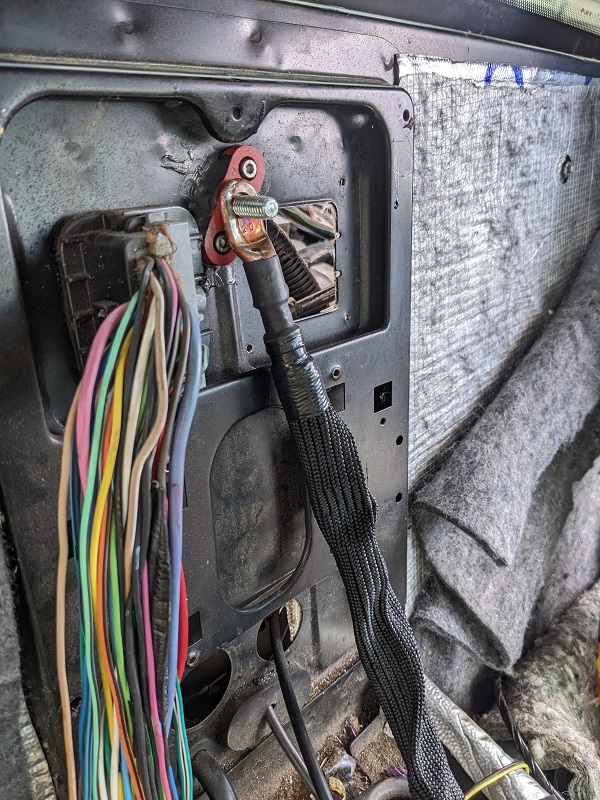
Last weekend Mike installed the power distribution bulkhead pass-through. Instead of running the main power cable under the car as many Fiero owners do, we are running it through the car cabin.
He repurposed the bulkhead opening where the clutch master cylinder was located, and then made a spot for the second pass through in the rear where other wiring for the car moves through.
Frunk:
Rear of cabin:
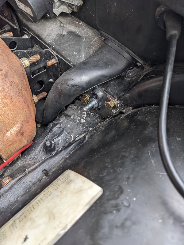
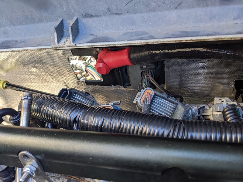
We put on the high abrasion protection sleeve I had bought, even though it isn't red. I tracked down some red boots with the proper diameter to use, and installed those at all points. I didn't take a picture of the frunk-side after I put the boot on. So here is a picture of the cable bolted in when we were doing test fitting.
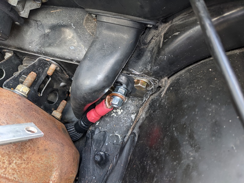
And here it is in the engine compartment, the sleeve here is both abrasion resistant and has a very high temp protection.
Once everything was done with running the main power, we put the aux. fuse box pack into place.
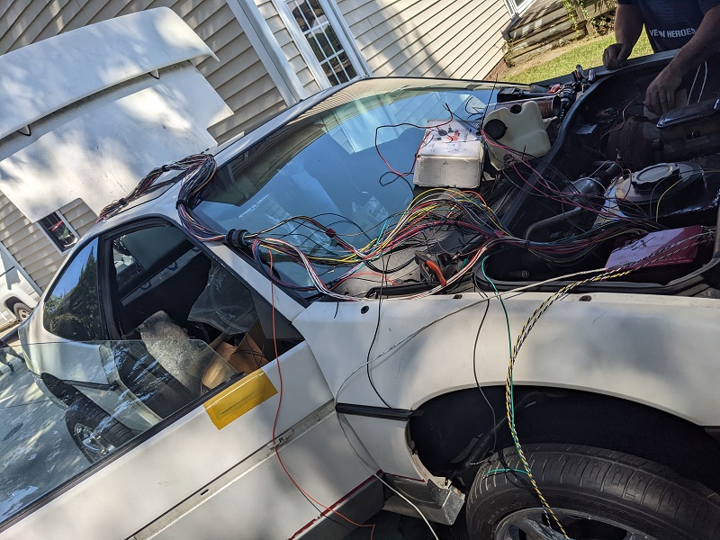
Mike then got out the partial ECU wire harness components he had made over the last few years, and it was long enough to where he could lay it over the car and connect all points. He said this will make it really easy to test pin-outs and do any troubleshooting.
I joked that we should just p-clamp it to the body like that when it was done and call it a day.
The last thing I worked on was the C500 starter pin-out issue. I think I mentioned last time we found out (the hard way) that the C500 engine connectors had different pinouts, and the starter wire is in a different spot on the auto-transmission Fiero vs. the manual.
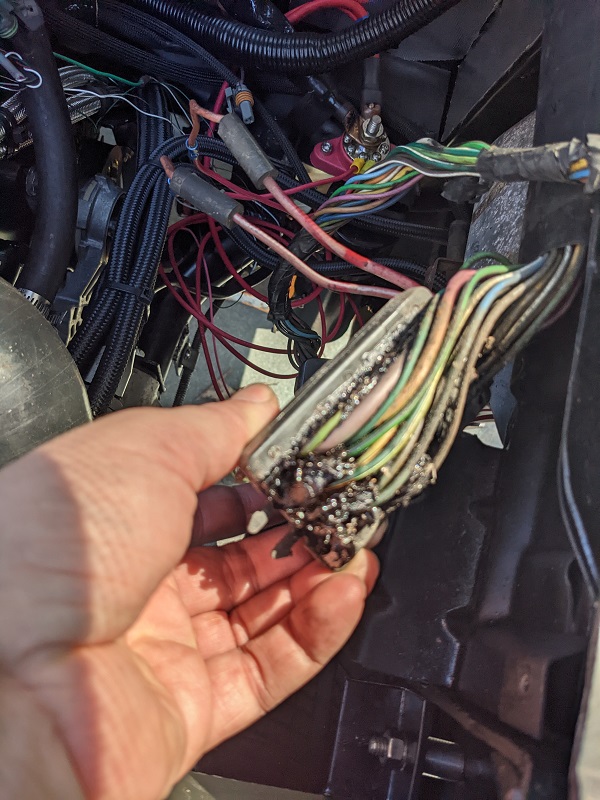
I did a post looking for the connector I needed, and Raydar suggested I disassemble the body-side of the C500 and move the pin.
So I opened that thing up... and put it back together. It's understandably full of the non-conductive weather protection goop, and I believe the white strips are the edges of the wire locks he told me about, which were also caked up in dirt/grime/goop.
At this time, I'm going to keep hunting for the proper engine side of the connector. Repinning the C500 will be a last resort.
[This message has been edited by Trinten (edited 03-26-2023).]
Sorry it's been a while guys. Between me being out of town, Mike having to work some weekends, and the fact that wiring is a slow and tedious process, progress has been slow!
To go back a little to a post I did in July when I talked about the shifter cable (and having to install it backwards), I did find I took pictures of it!
You can see in the first picture, Mike modified the back section of the Fiero shifter assembly with a part from the Caddilac shifter bracket that was originally by the transmission. This was to secure the cable properly and allow it to be adjusted. When installed "the right way", the non-flexible arm was too long.
The second picture is the new mount that Mike created for the transmission side. This is a two plate system that 'clamps' around the cables bracket engagement. we tested and adjusted the shifter through all the gears, and it's all working.
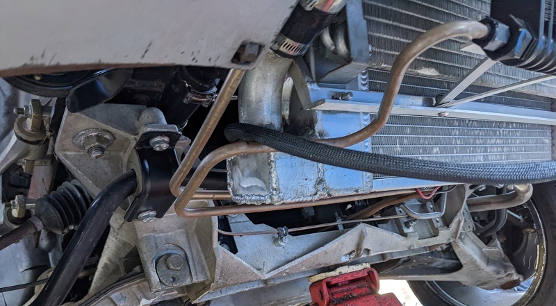
I was under the car at one point, and took a moment to admire the time and effort Mike put into bending all that tubing for the transmission cooler. There were a LOT of bends. Looks freakin' factory!
So onto more recent things!
The first/current engine harness was used by modifying the original LS4 harness. This made troubleshooting things a little more difficult (ohming stuff out or what not), because the engine harness colors don't match the XFI colors, and while the Deutsch connectors are designed to cram as many connection points in there as possible with their spiral setup, it does make tracking pins/wires when flipping things around pretty damn tough.
Thankfully the issues we had were very few, and today, with 'key on', the XFI came to life (along with the EHPS pump) and saw input from all the (connected) sensors!
We were both very excited by that. There's still a few more sensors we need to get terminal kits for and finish pinning/wiring them, that will be next weekend, and then Mike hopes to "bump" the engine. Not run it for very long, just long enough to make sure the XFI is reading everything and it all looks correct.
After that will be finishing running the intercooler tubing, top off fluids, I think we still need to do the bracket for the oil dipstick to secure that in place, then rig up a fuel cell while we do idle tuning and check for leaks.
After all that, is fabrication of the fuel tank, fab up the hoses to go from it to the fuel pump, and wiring to make the gauge cluster work.
Also, I'm still trying to chase down a 86+ Fiero Engine harness from a car with a manual transmission. One vendor on here dug out his harnesses and sent me pictures, I identified the one I needed... but after asking him for a price, I haven't heard anything back in a few weeks, even after chasing.
Another vendor has been telling me they'll check, and then I wouldn't hear back until I chased them. Finally I indirectly asked them if they just didn't want my business, that got their attention and they asked me to call them tomorrow.
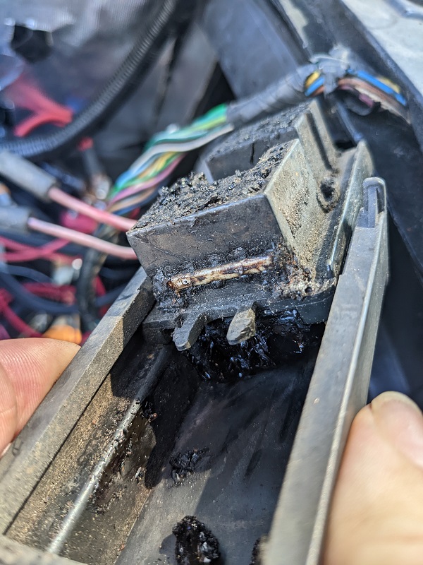
If all else fails, Mike will "cook down" the C500 connector we have and repin it, and we'll get more of that tar-goop to waterproof it.
[This message has been edited by Trinten (edited 03-26-2023).]
We finished getting wiring from the FAST modules to the engine (and after some head scratching with decisions made by GM around the cam sensor, and clarifying information from FieroGuru), we sprayed some fuel into the intake and did a very short run to make sure everything was working correctly. I did record it, but it was only a few seconds long, so I figure I'll wait until we have a constant fuel supply running to it and post up a longer then.
Mike won't around this weekend on account of Thanksgiving, so the next time I'll be out there will be December 3rd. The plan then is to run a hose into a gas container and start doing some basic tuning, and if time allows, have another can with some E85 so we can confirm the flex fuel sensor is working as intended.
Now I did (finally) find an 87-88 engine Fiero Harness from a manual car on eBay, from a guy that I've bought from before out in Nevada (no, not Archie, this guy is also named Mike, strangely enough). This was after striking out with Jon at Fiero Service (very busy guy, not great with follow-up communication, I had to do a lot of chasing).
I thought I had a lead with Larry as well - say what you will, Larry did come through for me on the D-plates. He even sent me pictures of harnesses and I spotted one that looked correct, emailed him back a few times asking him to for pricing, didn't hear back.
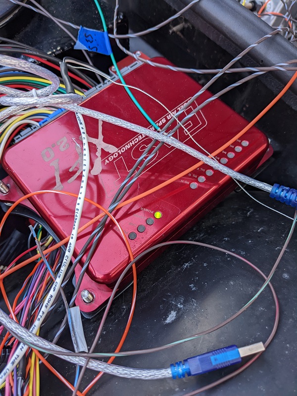
Either way, I got one! So we hooked it up, and the ignition key didn't fire the starter. This was a head-scratcher for us, because we had toned this out before when discovering we had the wrong C500 to start with. So instead of putting more time into that, we just used a jumper wire to manually trigger the starter from the engine compartment.
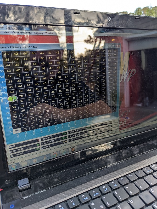
Only other hiccup is with the FAST software. Mike has it installed on a few laptops. The software auto-updates (I need to fix that in the hostnames file), so now, one one of his laptops, the newest software won't talk to my setup anymore. It probably requires sending my FAST units in to be flashed if it's not something I can do myself. I'm not planning on messing with that. I have the same version of the software installed on one of my laptops that Mike has on the laptop that is still working for him, so I'll just need to make sure to 127.0.0.0 the FAST software on it.
Also it's strange they don't have a direct USB cable yet, it still uses a serial cable, and then we use a serial-to-usb adapter. FAST sells a serial to usb adapter... for like 50 bucks. The 9 dollar one I have works just fine. lol
Anyhow, the point is, the engine lives! Woot!
[This message has been edited by Trinten (edited 03-26-2023).]
Gas tank construction begins Slow but important progress today. Last week Mike had gotten back his cardboard mock-ups for the fuel tank. He gave me the measurements and I ordered the 304 stainless.
Today was marking up the material and doing a lot of careful plasma cutting! Mike wanted to maximize the use of the space, and as FieroGuru has pointed out in other posts about making tanks, that is a difference between total volume and usable capacity. So we're trying to make sure any increases in volume will yield a reasonable increase of usable capacity. Because of the approach, there were a fair number of compound curves, but thanks to the effort on the mockup and the clean cuts of the plasma cutter, things are coming together pretty well so far.
Unfortunately, my phone decided to freak out and has stumbled into constant-reboot (rarely even reaching the lock screen, and will even reboot when I get to the factory recovery screen... so I think it's pooched). I don't do the whole 'cloud backup' thing, either. Unfortunately my paranoia on cyber security has also made it tough for me to setup things on my replacement phone. lol. Oh well. I'll get it worked out eventually, but any pics I hadn't already copied from phone to computer are gone - barring some miracle combination of buttons to get my phone to be stable long enough to copy things off. I'm not holding my breath.
So the pics we have are ones I took with Mike's phone that he emailed to me, which were after enough of the tank was tacked up to start doing test fitting.
We're going to move where the rubber hose comes from the fill tube into the tank, so I need to find the measurements of the ID and OD of that hose and get one that is longer at both legs (for both the fill hose and the breather).
Deatschwerks makes an adjustable fuel sender that we will likely use.
Mike started mocking up the trapdoor and the "sloshwall" in the tank. The trapdoor will be about a 1/3 from the back third, and another thing I'm going to call a "slosh wall" because I don't recall what he called it (a panel with a small cut out at top and bottom) about 1/3 from the front.
Here are the pics of the tacked-up, partially assembled tank shoved into the car for fitment checks.
[This message has been edited by Trinten (edited 03-26-2023).]
This weekend was more working on the fuel tank, and a few other odds and ends once we reached out limits with the tank for today. As mentioned before, the tunnel has some hourglass / mirrored sawtooth curves to it, so the top of the tank follows that.
Using a giant C-clamp we will bring in the sides to weld it without putting creases in the tank that don't need to be there. Before we do that we're going to get the baffles and trapdoor put in to add rigidity to the sidewalls. The bottom of the tank is marginally trapezoid shaped, so there will be an opening where the baffles can be tacked to the flat/wide bottom, before the angled corners are welded on.
It's slow going, a lot of measurements, marking and careful cutting with the plasma cutter using tall angle iron clamped on for guides.
Mike's also given me the information and plans for the fuel level sender he wants, and how he's going to run the fill and pickup piping. When it's all done and we do our leak test, we'll empty it by pumping it out through the pick-up into 5 gallon buckets, so we can get a measurement of the useable capacity.
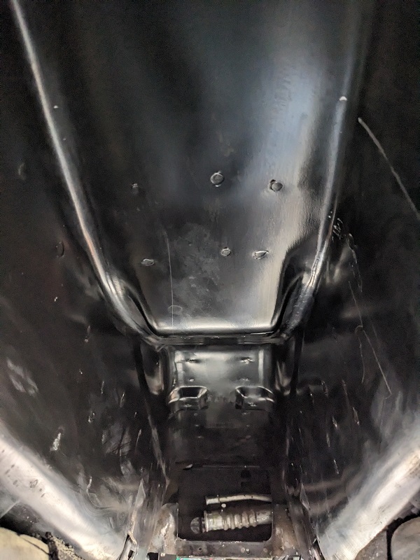
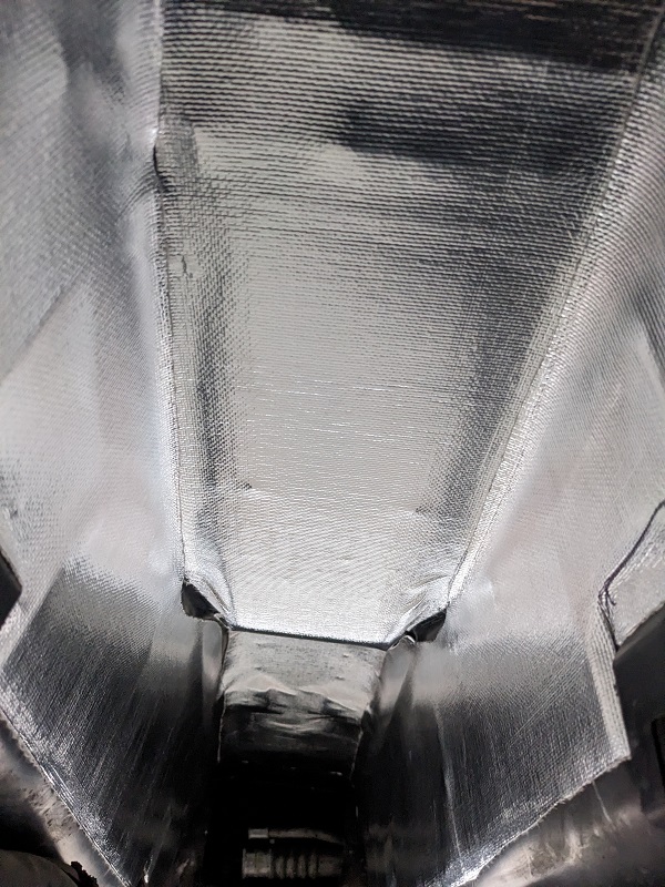
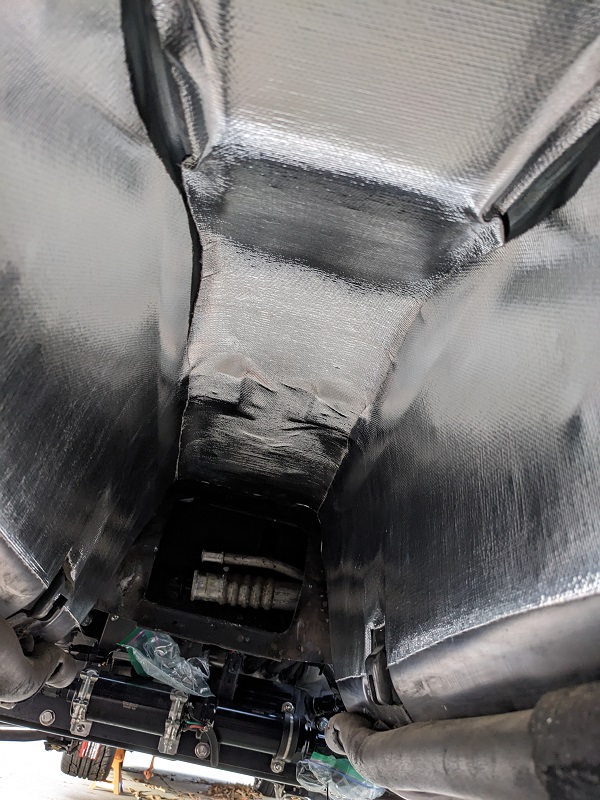
I took the time to clean out the tank tunnel, and put in temp/sound insulating material. You can see how some of those curves, especially at the top came into place with fitting in the insulation. After I took these pics I used some small pieces to fill in the exposed spots.
Previously when under the car I noticed the plate we made to mount the flex fuel sensor had started to rust. I thought it was a part we forgot to send off for powdercoating, Mike said he thought we had made it out of stainless (apparently not). So I took that off and he used some of the 304 I got for the fuel tank to make a new plate.
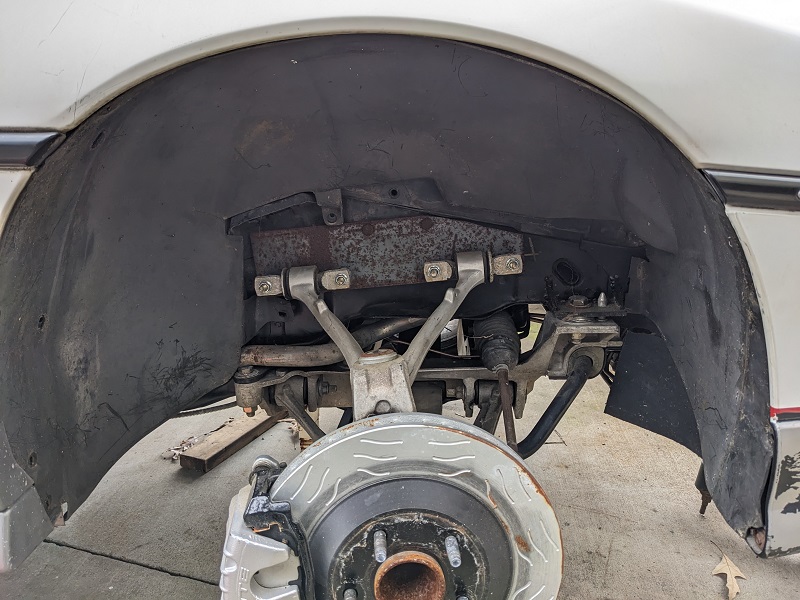
Mike also did a test fit of the wheel well covers, and was amazed to see they fit in there and around the Corvette suspension without any major issues.
The mounting bracket for the upper control arm is not welded in yet. Mike wants to get the car to an alignment shop and make sure everything aligns properly with plenty of adjustment room left before he welds them in.
[This message has been edited by Trinten (edited 03-26-2023).]
Fuel level sender ISS Pro was great to work with. I sent them an email, they emailed me back within an hour to ask when it would be a good time for one of their techs to call me.
Don called when they said he would, he went over everything with me, tank placement, headroom for the cap, other things they could do to the unit, they were even open to making the lead wires any length I wanted.
So it'll have a coating to protect the electronics from E85, the appropriate length (they go by half-inch increments). They had it made for me in less than 3 days, and the price, with shipping, is the same as it would have been buying one that didn't have the features I needed (namely being E85 compatible) from one of their resellers on Summit!
He even took the time to make sure I understood how the tube style senders work (theirs in particular has a 9-step sender), so it won't be as 'smooth' as the arm-coil-resister style. I'm not too worried about it, I don't like getting under a quarter of a tank of fuel in any car I drive.
[This message has been edited by Trinten (edited 03-26-2023).]
First up is I bought the Fiero car cover through the Fiero Store, and so far I am really impressed by it. It came with extra plastic grommets, it was very well fitted, seemed well constructed. We'll see how it holds up.
Recently I worked on fitting in the rear wheel well covers, I bought all new hardware from Fiero Store, because it's inexpensive and then not fighting rust and grime, Both sides required some trimming, the passenger side less than the driver side. This was mostly because of the Corvette suspension and some other places where Mike had massaged things to make the clean fitting openings for the intercooler tubing.
To help make the wheel well covers look 'cleaner', Mike gave me the name of a company he uses to buy neoprene sheets. Apparently some G-Body cars had neoprene parts to their wheel well covers to act as flexible flaps, so we're going to apply that same approach here. I took pictures of the progress, but figured I'd wait till they were done, take pictures, and post it all up together.
We started doing our checklist to do wiring for the FAST TCU. As I did with the XFI, I'll be contacting my wire supplier for the appropriate striped wire color combinations once Mike let's me know what colors we need for my setup. I want to do as much as I can to use colors that will be consistent with the FAST diagrams, to make any future troubleshooting or repairs easier. Hopefully the wire company won't have a large backlog that we need to wait through.
Beyond the stuff on my car, Mike has been busy working with the G-body race team with prepping their car for the season, and starting to see what pieces he needs to do his F23/3800 swap on a Fiero he picked up shortly after mine got to his place. This one is separate from the Indy he'll be restoring. He informed me won't be going with me to Carlisle this year, but will definitely be at the 40th.
As far as other customer projects, someone picked up an off-center stage 2 GN motor, so he's swapping it into that guys Grand National, with the intention of having it ready to go to the big Grand National even in Bowling Green. He's a busy guy.
Remaining checklist for my car that I can think of:
1) TCU wiring 2) finish welding / testing / measuring useable volume of the gas tank / installing it. 3) Routing Intercooler water hose 4) Install my cruise control unit 5) Alignment 6) finish welding the front upper control arm mounting plates once we know it's well centered (hence the alignment being first) 7) install new switch module and key cylinder in the steering column (my request, doesn't seem to be necessary) 8) Toss in a basic interior for now 9) Tune it!
That's a much shorter punchlist than what I had a year ago.
The stainless fill and vent tubes runs to the center section of the tank, filling it from there so it wouldn't be stopped by the trap door (additional fabrication work, but worth it).
We set it up and did a test of usable capacity (how much gravity fed out of the tank when it was level, until the stream reduced to pencil size. Mike referred to this as "sitting idle" usable capacity, citing that if one where to goose the gas a little, fuel would rush back and be retained near the bank of the tank for a while thanks to the trapdoor.
We then tilted the nose up to see how much more was left in the tank. Those number will be posted later... and we are happy with them.
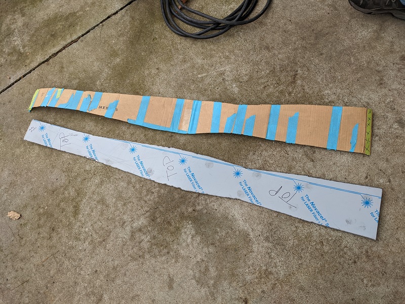
To recap, last year Mike used cardboard to workup a form fitting template to the tunnel in the Fiero. We wanted to use as much of the space as possible.
He then taped the template together, and had hoped a friend of his that owns an industrial overhead door company would have found the time to cut out the more uniform parts and bend them in a brake for us. That didn't happen, so Mike had to put in considerable more time with the plasma cutter and welder to put the tank together.
I'm at about $800 in materials in the tank (the flat stainless, tubes, bungs, stainless trap door).
Onto some pictures!
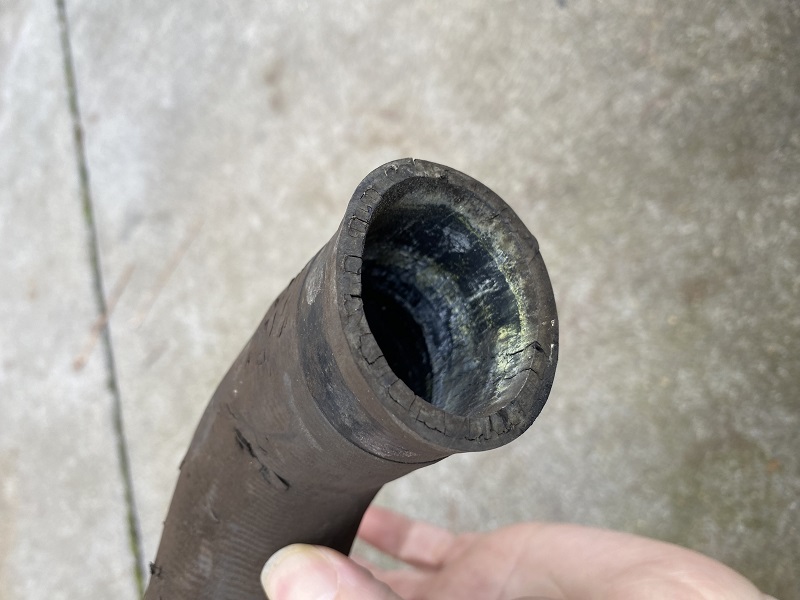
The rubber filler/breather tubes in the Fiero were sonic welded together, and both were in bad shape. So replacements were sourced. Here a picture of the old filler tube.
Here is the template and top part of the tank before we bent it to follow the 'dip' in the tunnel. This is a great image to show some of the complexity that went into the tank. After the bends were introduced, it made tack welding a few spots a two man job, as there wasn't a good way to get clamps to hold things where they need to stay and still be able to weld.
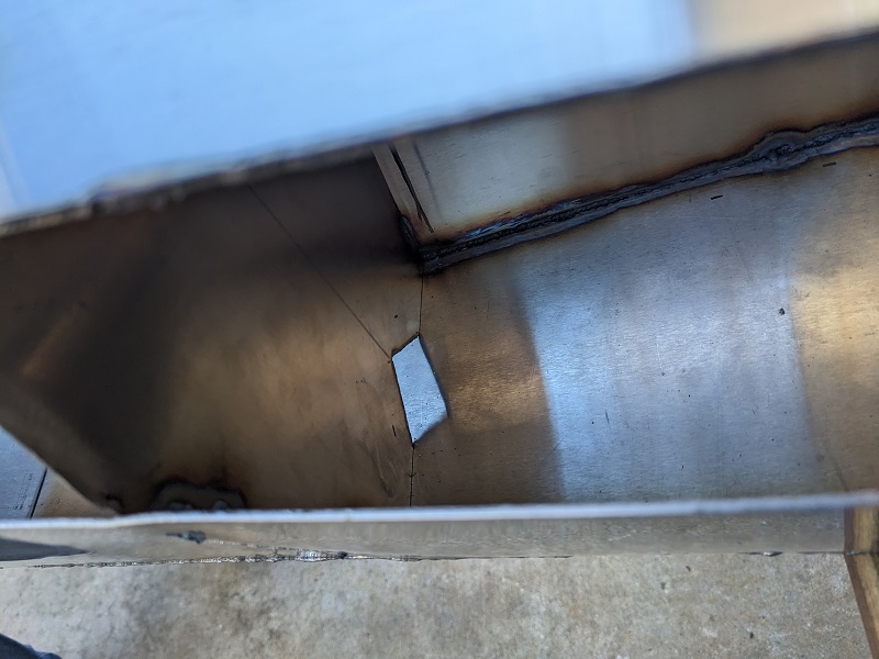
Before Mike welded on the additional bottom extension I suggested (it's still not the lowest part of the car, don't worry). I took the opportunity to take some pictures of the front baffle. There is an identical notch on the opposite side. He used the baffles as internal structures to secure many of the pieces to a 'core'. The position of the baffles was picked by where the tank straps sit, insuring rigidity.
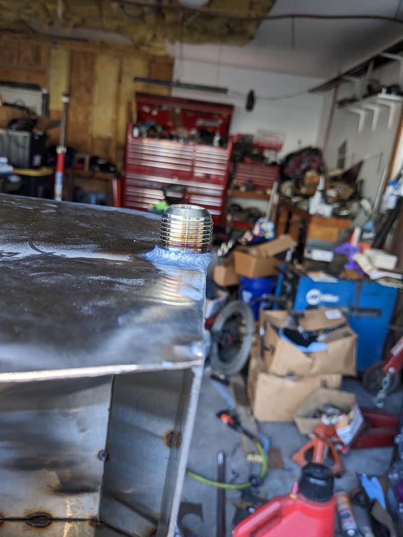
Next up is the stainless supply bung. We discussed the idea of having a "blister" of some kind, that would create an internal 'dip' for fuel to drop into, but we decided against it, as that would have become the lowest point under the car, and a higher chance of something happening that would compromise the tank. Besides, with the trap door, it should keep fuel back there without issues, negating most of the benefit.
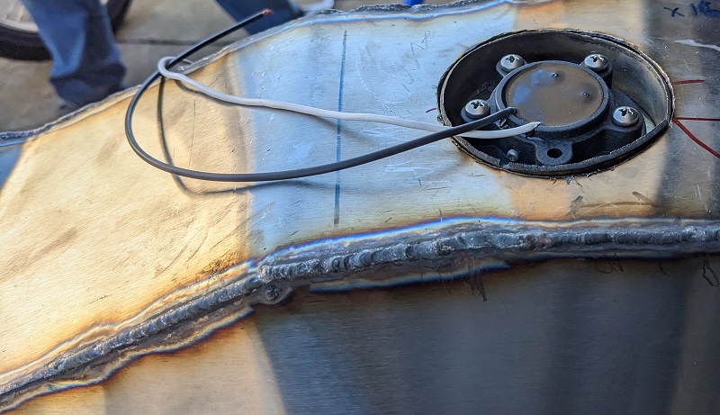
I talked about the fuel sender alright. Mike's measurements were spot on for it, meeting their requirement for space at the bottom of the tank, and let Mike recess the mounting point of the fuel sender. Here's a picture of it during a test fit, before he welded it into place.
In the tunnel there is this pocket that we originally wanted to make use of. Unfortunately, in our first test fit we found that it would be impossible to have enough wiggle room to connect/disconnect fittings and hoses, since the nose would be wedged into the pocket and the back of the tank would have to 'swing' up and down into position. So Mike had to cut off that portion and weld it back up. Capacity lost was minor, less than a quarter of a gallon.
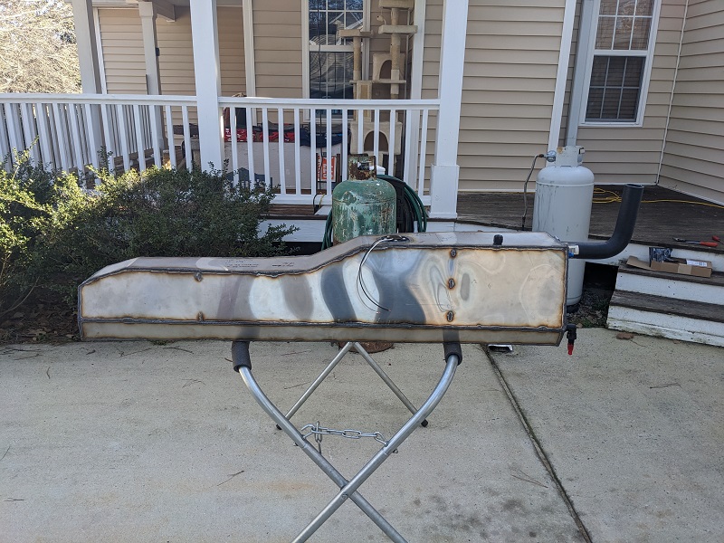
Here's picture of it setup for our leak and capacity testing. There is some minor distortion/waviness to the metal. Stainless steel really dislikes being TIG welded in cold weather.
We capped off everything (including small breather vent) and filled it up to the top of the larger fill tube, which is above the tank. This, and rotating the tank, allowed us to make sure all the welds were tested. We found one pinhole. Not bad for so much welding!
After that, it was "idle usable capacity" test time! Place your bets! (we did!)
We used a 5 gallon bucket, and filled it up 3 times before the stream from the tank got to be less than pencil sized in width. That's 15 gallons!!
After lifting the nose a few inches, (now emptying it into a 1 gallon jug - empty windshield wiper jug) we got to a little over the halfway mark. So overall capacity is ~15.5 gallons. Given that the later, larger stock tanks were 11.9 total capacity gallons (and most people guess it's about 10.5 - 10.75 usable capacity), I'll take the 4+ usable gallon increase!
Next weekend will be installation and then pressurizing the fuel system to check for any leaks there. If no leaks, we will begin the idle tuning of the car!
In before the comment: Yes, Rodney Dickman makes exact replacement tanks, and they are top quality. We wanted to see if we could make something to hold more, and we wanted it to be made with 304 stainless. If we ran into issues, or hit a time crunch, Rodney's tank was our backup plan.
[This message has been edited by Trinten (edited 03-26-2023).]
I had hoped by now to be able to post a link to the engine running. Alas we've hit some electrical gremlins that we are now chasing down.
The engine harness is the original one that came with the LS4. This one is temporary since I'm using a Drive By Cable setup, so there were some extraneous wires from the DBW that aren't being used, and some wires that were added for things like the TPS.
Back in November, the FAST setup was talking to the engine, and we were able to get it to run by spritzing some fuel into the throttle body. FAST showed injectors were firing (though nothing to fire, no gas tank at this point), and it obviously had spark because it ran for that few seconds until it ate up the fuel.
A few weeks ago, after installing the tank, the XIM part of the fast was refusing to fire the injectors. We confirmed it was seeing the injectors by doing a fault test. So Mike went through the lengthy troubleshooting (starting with Canbus wires, terminators, etc). Yesterday we finished ohming wires and checking for loose pins, and found our loose culprit.
We were excited, the XIM was now seeing all it's inputs and was trying to fire off the injectors! We put the fuse in for the fuel pump, starting cranking.... no start. Check everything, try again. No start. Confirmed the injectors are spraying fuel (the mufflers and their mounting 'T' is not connected, and after a combined 30 seconds or so of cranking over a few attempts, fuel was at the opening of the exhaust).
Now since it ran for a few moments in November, we didn't think it was a spark issue, but that's the next thing to check. And here's where it's gotten a little strange.
There is spark. Very weak spark, like sometimes you'll 'hear' the spark more than see it.
1. We check voltage coming into the coils. 12.7v.
2. Grounds are good, this grounding to the block, which has good grounds to the frame, because the starter is grounded to the block and is spinning the engine without any issues. We also tested it by grounding the spark plug in different ways (first by touching the threads against a bolt on the block, another time with a wire leading directly to another ground. That second one was my idea, Mike thought it was unnecessary due to the strong starter rotation but he was kind enough to humor me).
3. We double check the dwell times (the D585 coils need a dwell time closer to 4 - 4.5ms, versus the default 5.5)
4. We check a few other plugs, all the same (also, no fouling or anything else, they look good)
5. We swap off a coil for a known good one from an LS1 (and adjust the dwell time for it). No change, spark is still barely there.
So we hook a laptop up to the FAST so we can log what's going on. When cranking: 1. The engine shows 250-300 RPMs, then a moment of "zero", then jumps back up again. It's very consistent. Mike thinks that might be normal for a 24x reluctor wheel, but he's going to check.
2. During those times that the engine shows the 250-300 rpm, the FAST is telling the injectors to go to 100% duty cycle! Mike was surprised by this, comparing start up logs to the FAST system in his car, that is unusual behavior. It also made him go and pull more plugs to see if any of them were fouled. They weren't.
3. We may have either a bad TPS sensor, or there is some EMI that we need to hunt down and fix. FAST is logging an erratic TPS signal, jumping from 0% to ~15%. Mike has one of those clamp shaped tools that you can use to check for EMI, so that is on the list to do later, to see if need a new sensor or need to shield something.
The first thing we're trying to figure out is the weak spark issue. We have good grounds, coil packs are good, voltage is good, so that's our head scratcher right now. If anyone else has any thoughts, please let me know. There's nothing in the FAST configuration (except dwell time) that we could think of or find that would affect this.
We found the problem with our starting issue, and got it running!! Also found more hiccups!
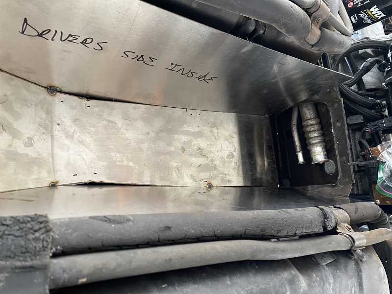
To cover the no-start issue first, the crank position sensor was bad. Mike figured it out by doing a bunch more logging and looking at dashboards on the FAST while he had me crank the engine for a few seconds every few minutes.
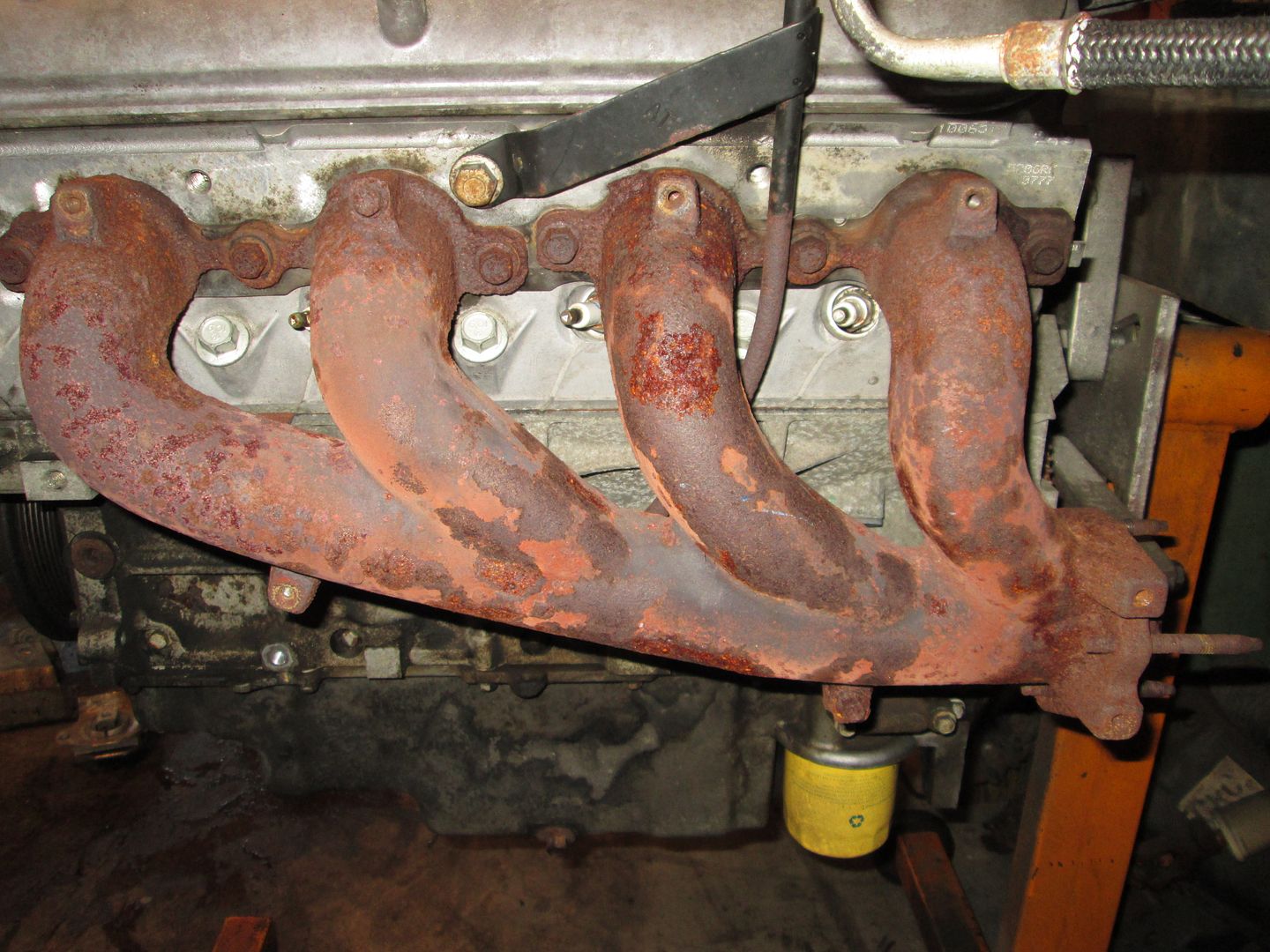
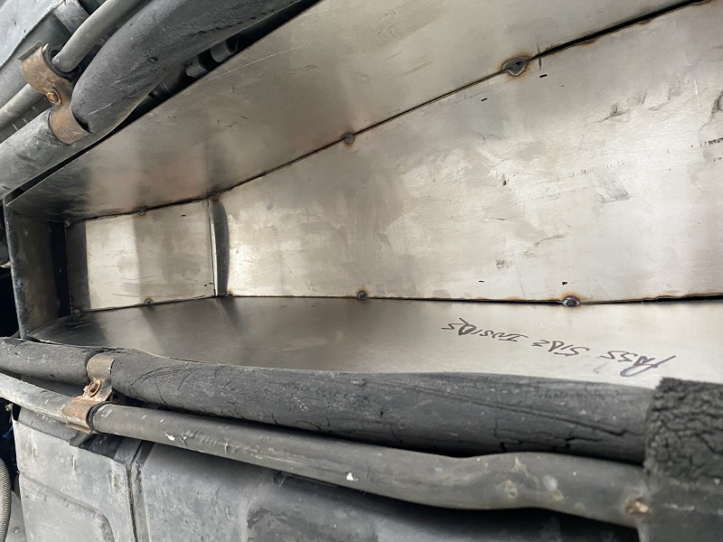
This let us test our disassembly options. We took off the passenger wheel, took out the wheel well liner, took off the header bolts of the rear bank, opened the V-Clamp at the end of that header, and with a little wiggling and leverage, slipped the exhaust manifold off the studs and out of the v-band, and then slid it sideways out the side of the car. Not having strut towers is awesome!
Getting the sensor out was a little bit of blind work, but Mike is used to that kind of stuff, so it wasn't an issue. He also found this other testing tool for testing spark. It's difficult to describe and I didn't take a picture of it, the spark plug screws into a collar that has an elongated ceramic center piece and a tall wall around it. He says it needs to show strong spark for it to jump all the way up the ceramic insulator and hit the wall. With the sensor replaced, it did just that!
So now we have spark! We put everything back together (which did take two hands, I had to lean over the side and reach from the front side of the vband to hold it in place while Mike latched it), turn on the fuel pump, try to start it... it sputters, crank crank crank. Sputters... crank crank. Okay. Back to the logs.
We see the TPS is still doing bizarre signaling. To rule out an EMI issue, Mike simply unplugs it. Problem goes away. He plugs it back in, and tries the travel of the TPS. To summarize how bad it was, nothing would register till about half-throttle. At full throttle, it was only reading 85%.
So he goes into his boxes of spare and test parts and pulls out a used GM OEM TPS. We slap that on there.... all the issues vanish.
He then played with the timing a little, added a lot of fuel, and we got it to where it wants to idle. To rule out the IAC (which came with the TB along with the TPS), I've ordered a new one of those as well as a new TPS.
Next weekend will be installing the new TPS and IAC, getting the wideband hooked up to the FAST, start working on the controller for the coolant pump. That could get a little messy. Mike's TIG welder (I think TIG, he has both TIG and MIG) is acting up, and there is still a pinhole in the radiator he needs to fix. But we can't do long running idle tuning without getting the coolant system working properly. So we'll deal with a slow drip of coolant for the time being.
I have a video of it idling without the mufflers on, when I get it uploaded someplace I will post a link.
For various reasons I'm not uploading to youtube, so I droppd the video file on the web server that was hosting the defunct NCFiero Forums (I waited too long between version upgrades... and... it went badly. Still not sure what I did wrong. I've tried restoring things a few different ways, including wiping out the DB, wiping out the forum install, putting back on the version I had, restoring the DB I backed up before the debacle... still broke. So it's a lost cause and will eventually go away).
In the meantime though, here is the video (well, audio?) of it running. This is from Saturday, the only tuning done was adding some timing and incrementally more fuel until we got to this point.
This was recorded on an android phone - not sure why the video won't render on the page, plays fine when I open it on my Windows laptop.