Looking great as always Guru! I'd be highly interested in a set of your deck lid hinges. I can send you the hinges off my car if that helps. I now you are a busy guy - I'm in no rush but wanted to get on the list for future.
Thanks for sharing all your hard work.
Pat
Honored to own a page in Trinten's (Guru) Thread!
[This message has been edited by katatak (edited 02-17-2014).]
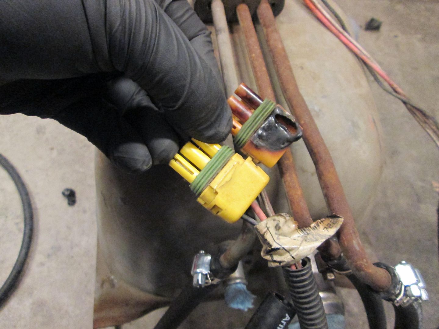
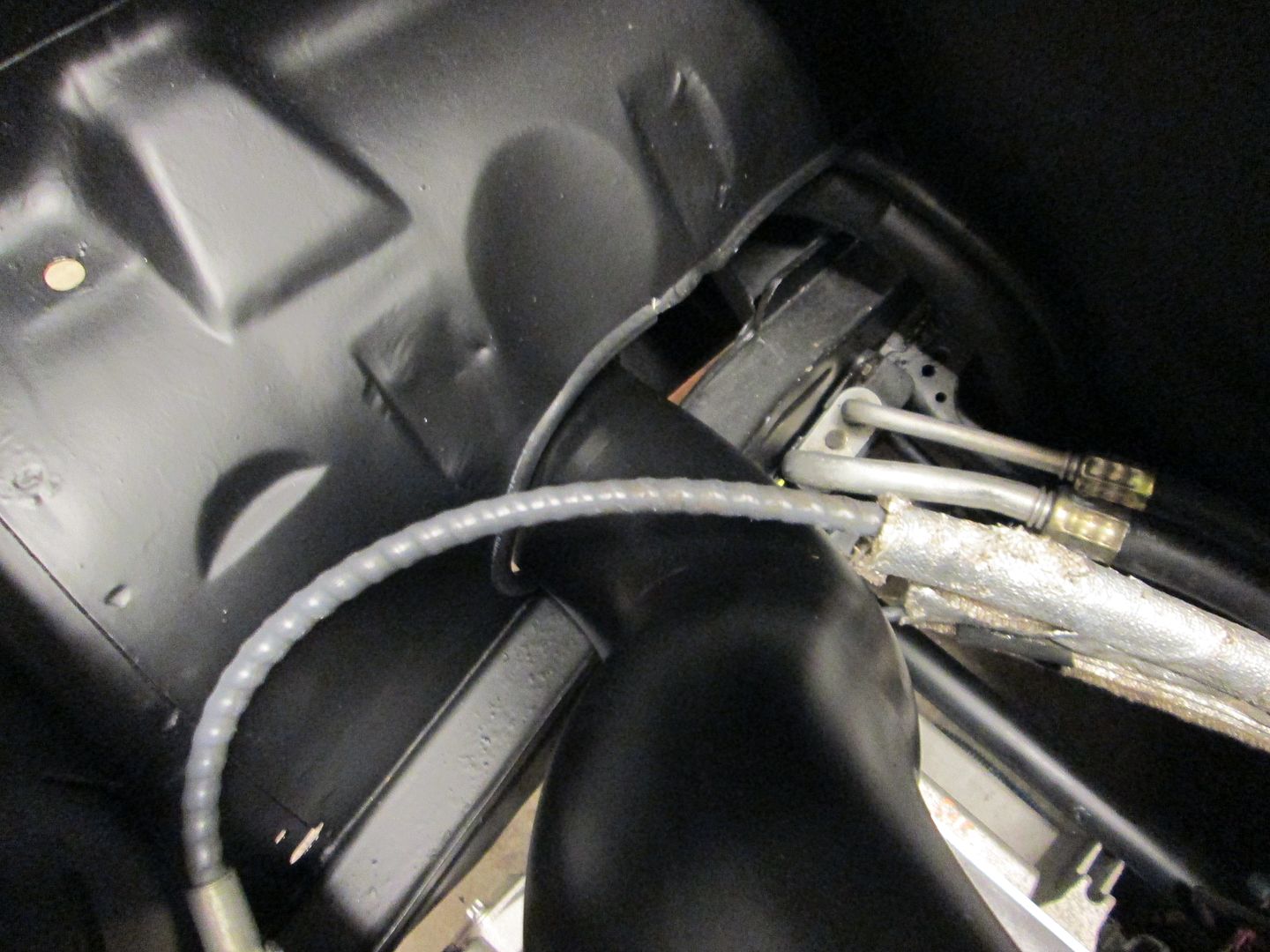
Monday I wanted to get the fuel tank back in. I swapped out the melted connector and installed the new rubber lines from the tank to the filter/regulator. Then slid the tank under the car, pushed it into place, pulled the straps around and then noticed/remembered that I twisted off both t-bolts when I removed the tank... so back out it came and into the house I went to order some replacements from Fiero Store. After that motivational setback, I decided to clean up the garage and call it a night.Only picture from Monday:
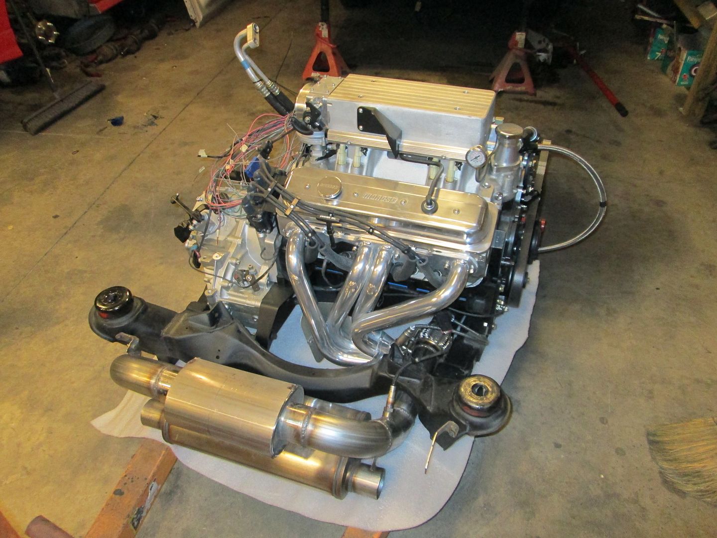
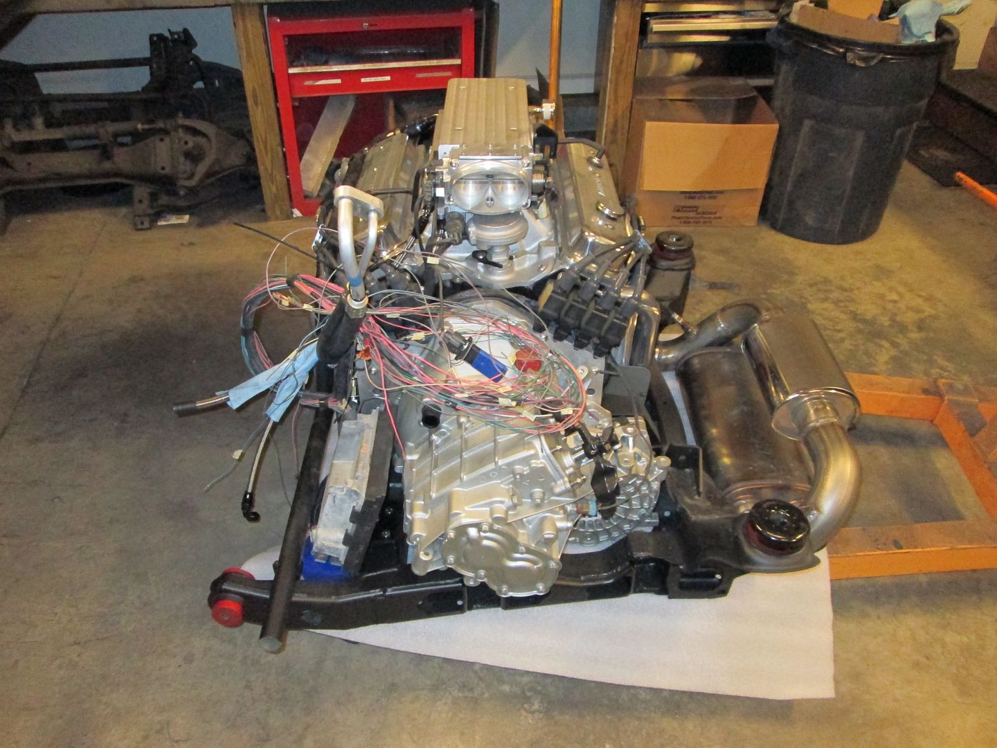
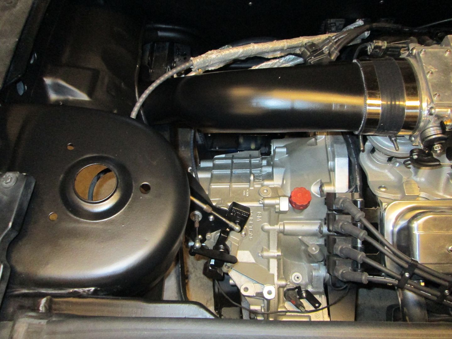
Tuesday was much more productive. I stole the battery out of the truck and used it to spin the engine w/o any spark plugs to get the oil circulating again and to check for any oil leaks. After that I installed: ECM mount, ECM, spark plugs, plug wires, and balancer bolt. Then removed the air intake and shifter bracket and got the engine ready to slide back under the car:
Engine/transmission/cradle is back in and the 4 cradle bolts are in place but not tight.
On Wednesday I will tighten the cradle bolts and hook everything up in the engine bay.
[This message has been edited by fieroguru (edited 02-18-2014).]
I missed the details of the engine, went back & looked... AFR heads are the tits, wish I had the $ for a couple sets (one for the 383 in my truck, one for the 350 in my Malibu). What intake is that?
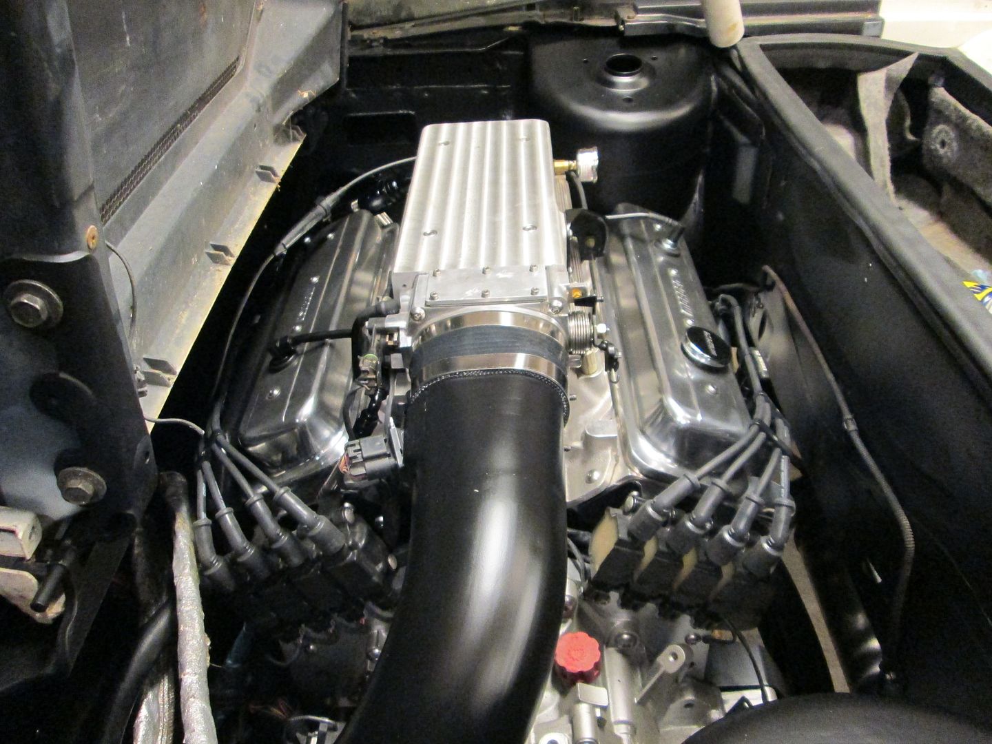
The intake is a (modified) Holley Stealth Ram setup.
I bought the setup from another member here on the board. It was originally modified to fit under a stock Corvette hood (it had decorative fins on top that he had lathed down, and trimmed down some other things). FieroGuru has modified it even further to make sure things would fit.
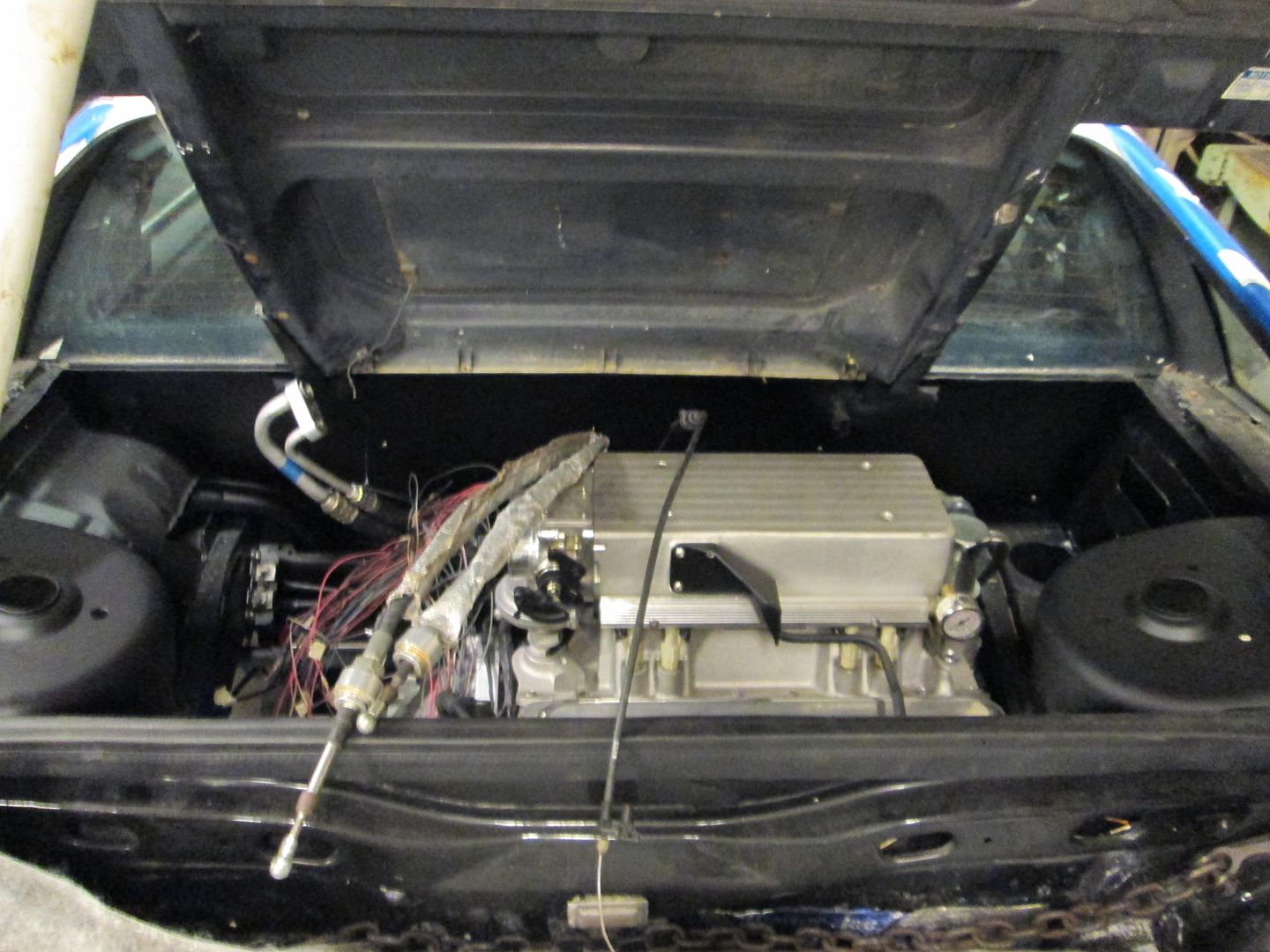
I wasn't able to fit the intake completely under the decklid and will have to remove a slight amount of material (about 1/8" to 1/4" deep):
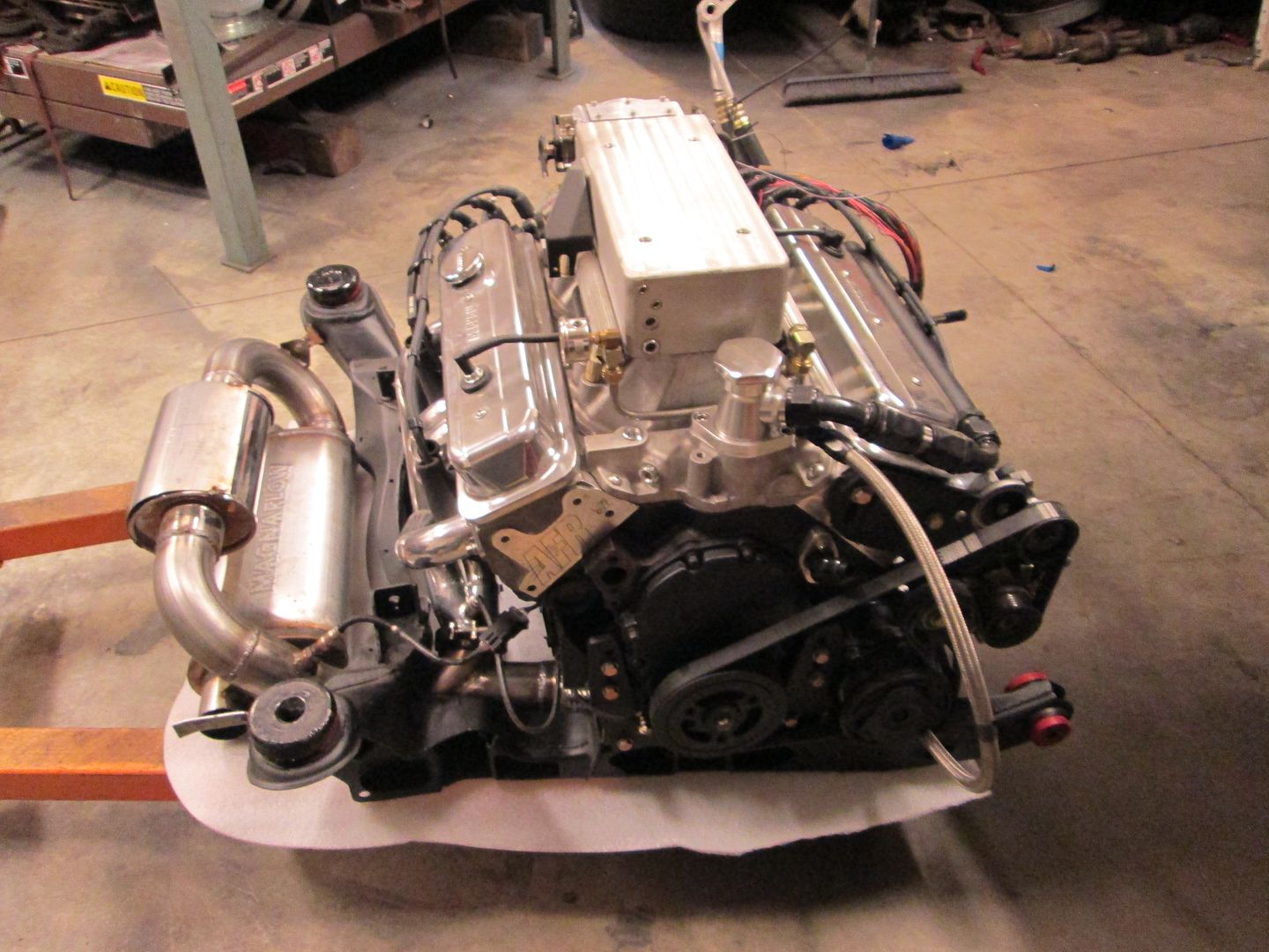
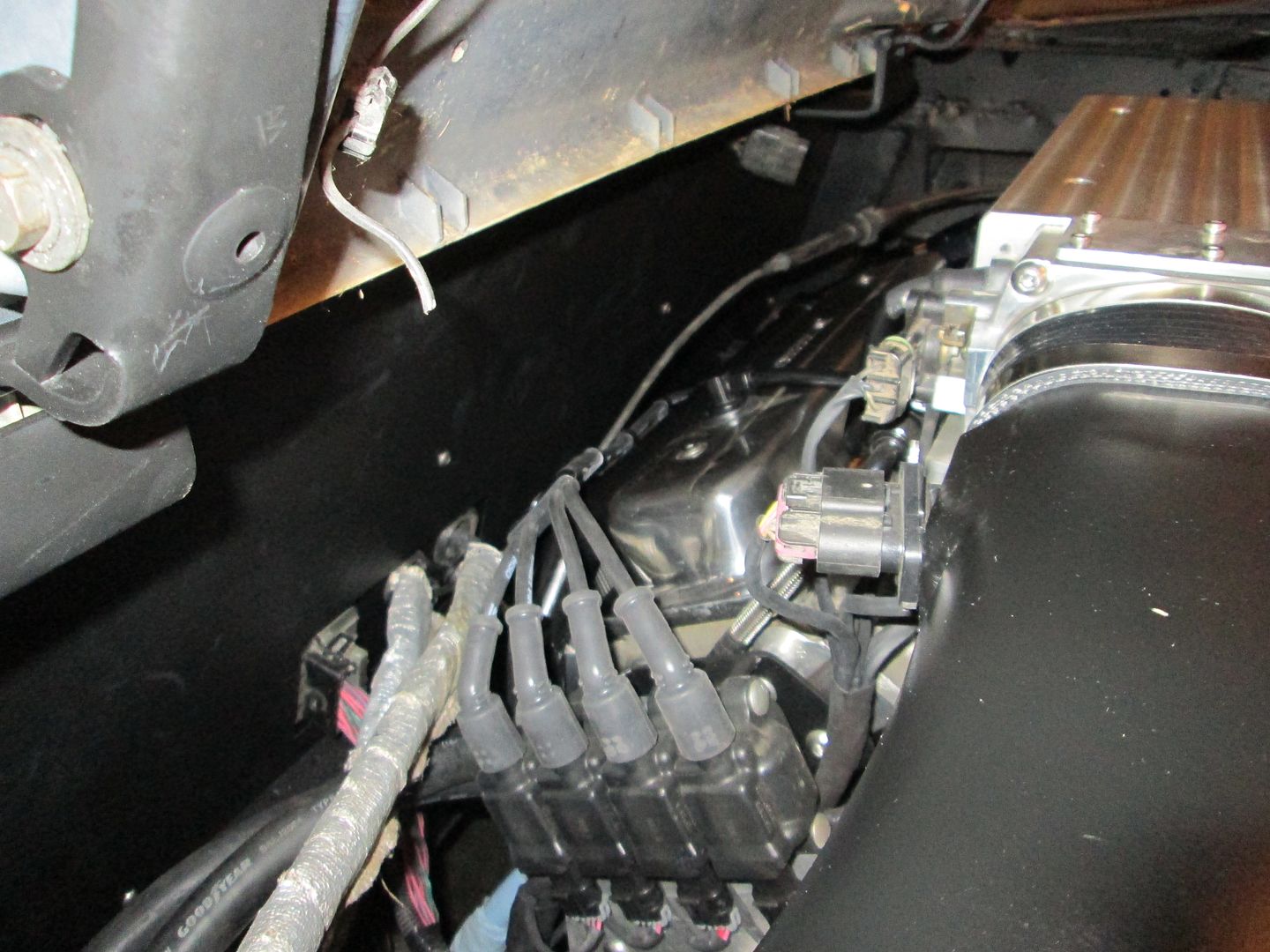
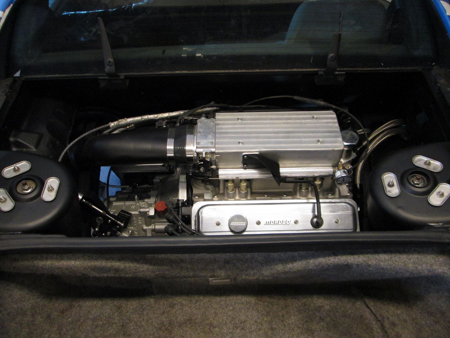
Pic of the engine from the side:
Here is a full engine bay pic of the engine. I still need to clean the bottom side of the decklid and install the struts, but this is very close to the final installation pic (engine side is fully wired too!).
Now I need to move to the interior and start working on all the interior harness terminations... that will take a couple of days.
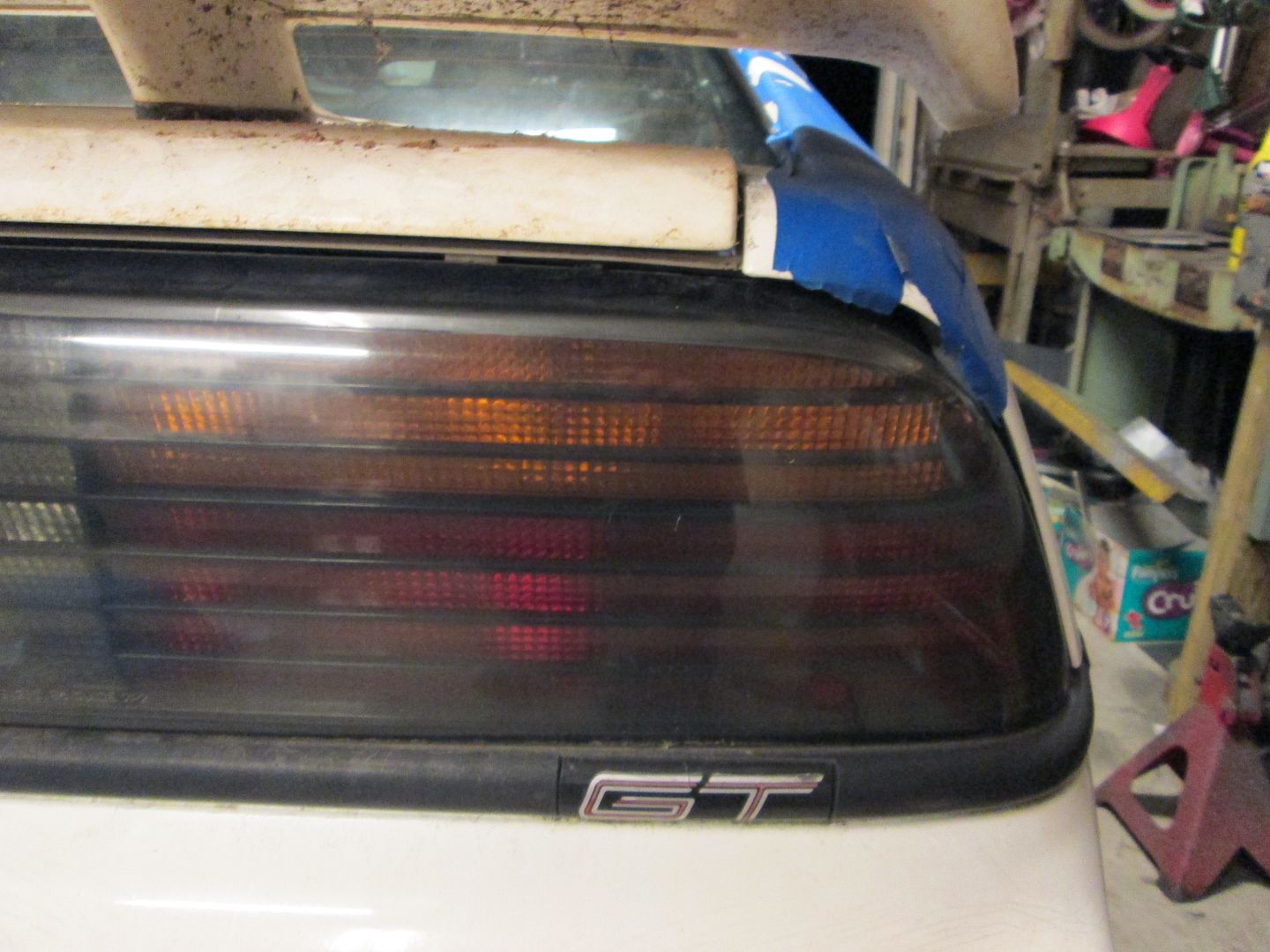
yeah, sorry about my old decklid being so terribly dirty. When I moved last year, I didn't have a shed or anything any longer to keep it in, so I had to set it in the backyard up against the house... I thought the overhang of the roof and gutters would help protect it - not as much as I hoped. It was pretty darn gross, but I didn't know it till CowsPatoot was there and we were loading parts up into his truck. Sorry again.
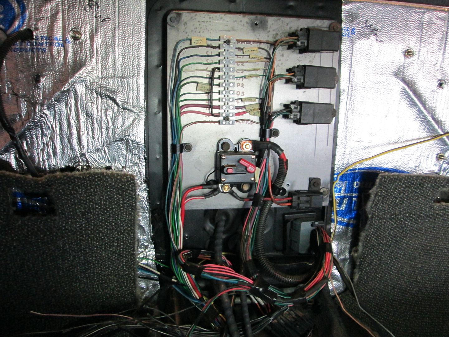
I am just about finished with the inside wiring. Just need to add a connector for the clutch switch and wideband input, wire up the wideband, and solder the terminal on the end of all the grounds. The 500, 203 and OBD2 connector terminations are all complete.
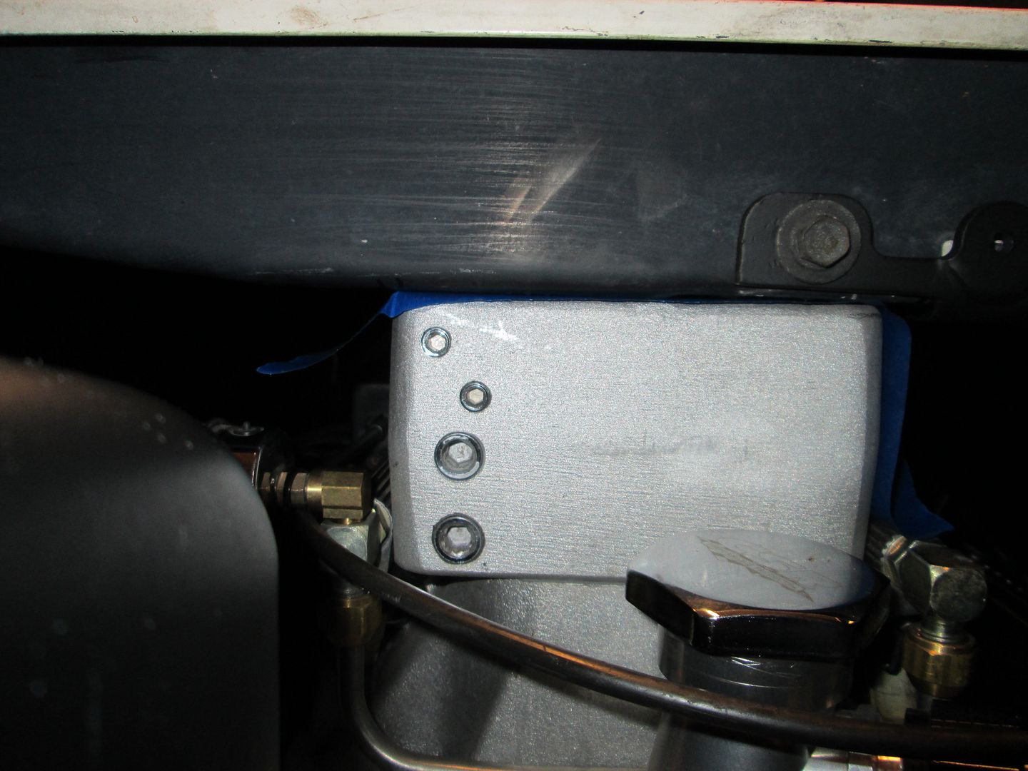
The terminal strip is the engine side of the 500 connector (and the fuel pump and water pump). The relays (top to bottom) are: Water Pump, Fuel Pump, and AC. Bottom right is the added fuse for the hot wire of the fuel pump. Circuit breaker is bottom center. The black vertical "wire" running parallel with the terminal strip is a 1K resistor between a fused 12V switched source and the tach wire. It is needed to boost the tach signal so the fiero tach can read it.
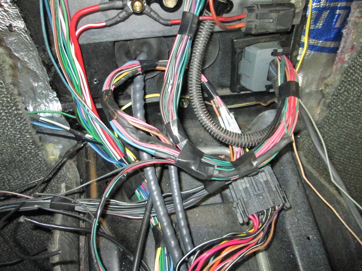
The harness comes in on the lower right of the console area, the 3 wires that immediately exit the loom are the clutch switch, wideband input to ecm and the wideband sensor harness. The harness loops around (I like to keep the harness long for any future mods) and splits with the OBD2 connector wires going to the front, all the 500, AC, Fuel Pump and Water pump wires going up to the terminal strip/relays, all the ground exit the harness to the left, and the harness continues to loop around to the 203 connector. Within the looping harness (thick black heat shrink tube at bottom of loop) bottom is the speedo circuit between the ECM and 203 connector so the Fiero speedo will work.
I will be traveling for work this week, so won't get back to working on this swap till next Saturday. Once I install the tank and connect the battery cables, I can try connecting to the ecm, do the first round of parameter changes in the tune and see if it will make some noise...
[This message has been edited by fieroguru (edited 02-23-2014).]
Just curious...why did you choose to use a terminal strip rather than a Weatherpack (or similar) connector?
Everything at this end of the harness must pass through the single bulkhead hole so there isn't much room. So far I haven't found a connector that is small enough and accepts the range of wire thicknesses that go through the 500 connector. The wires are long enough that a connector could be added once a suitable one is found.
There won't be any updates this weekend or next week.
I got back from my business trip yesterday, but I have to go back next week as well. With the potential ice storm coming in Sunday Night, I will head back to northern Indiana on Sunday afternoon and stay till next Friday. Maybe next Sunday I will have some progress to share.
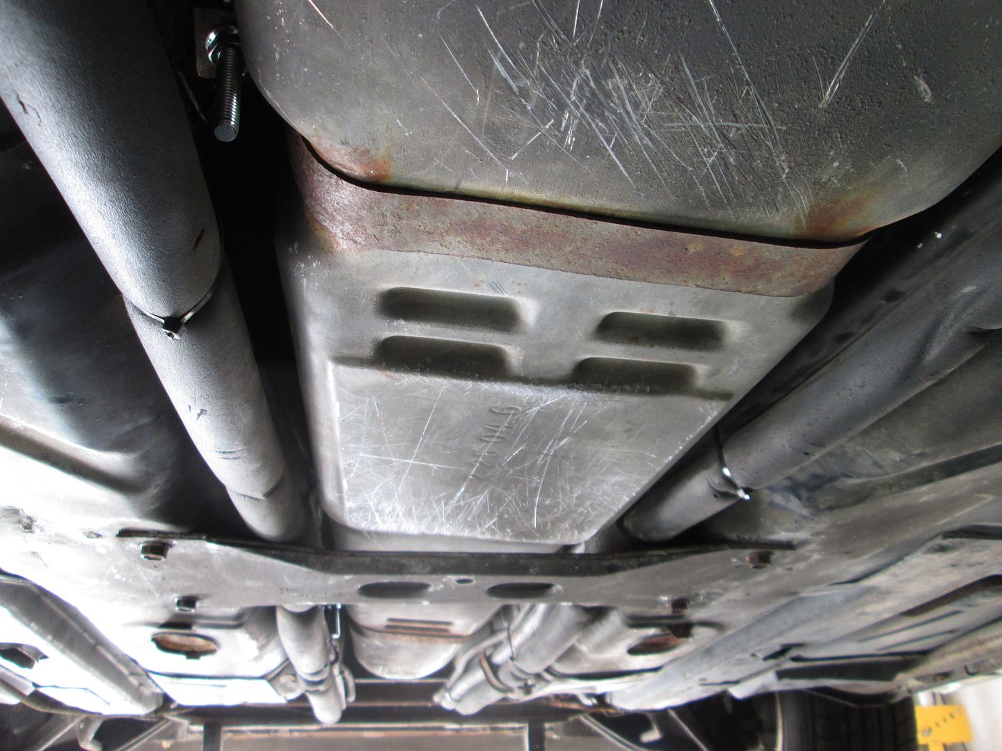
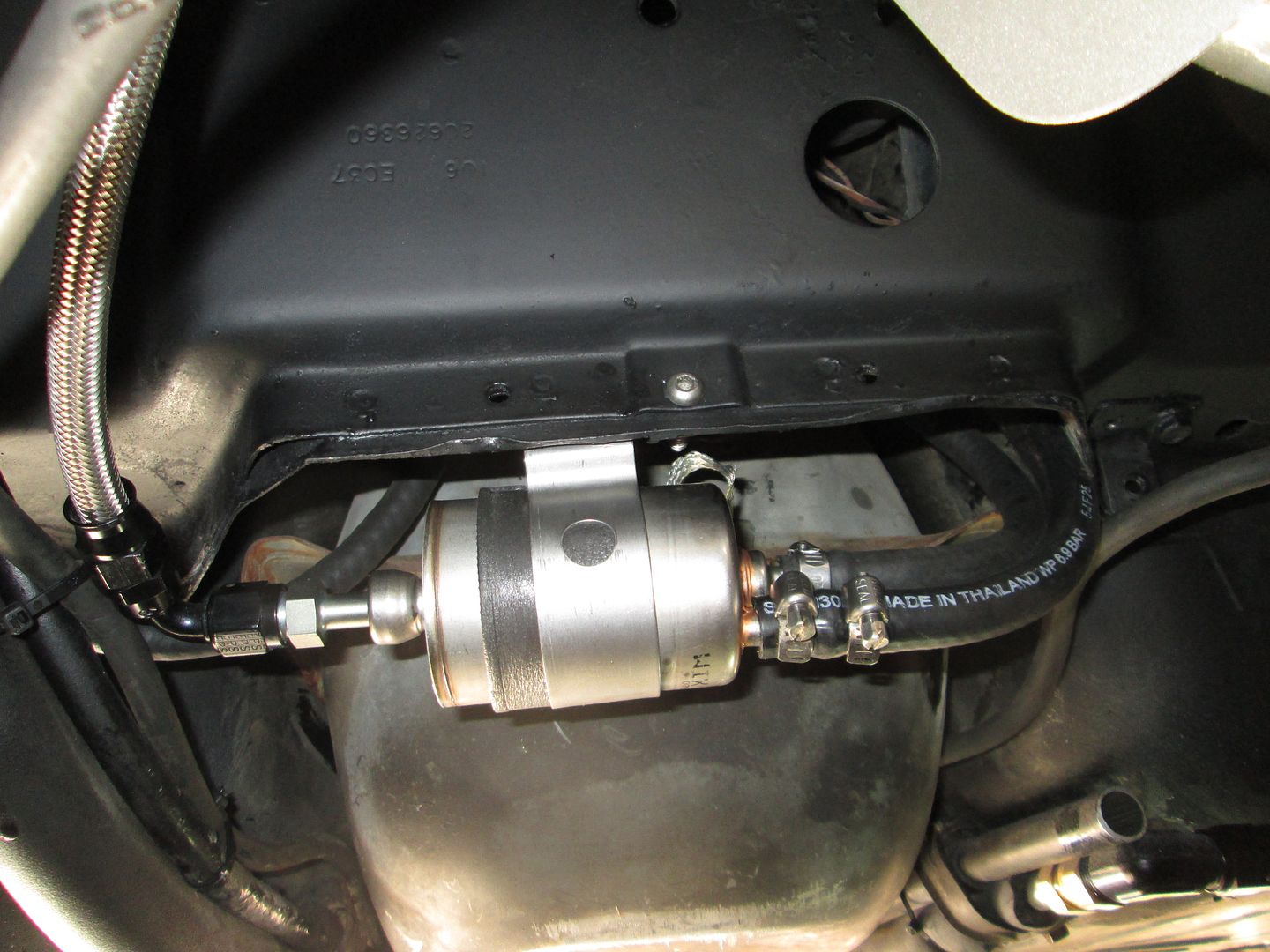
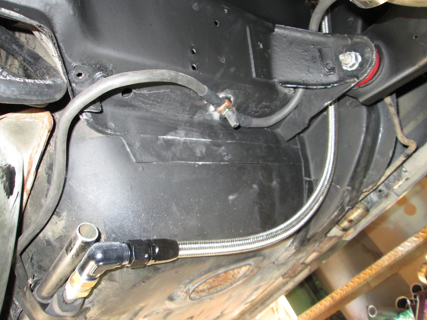
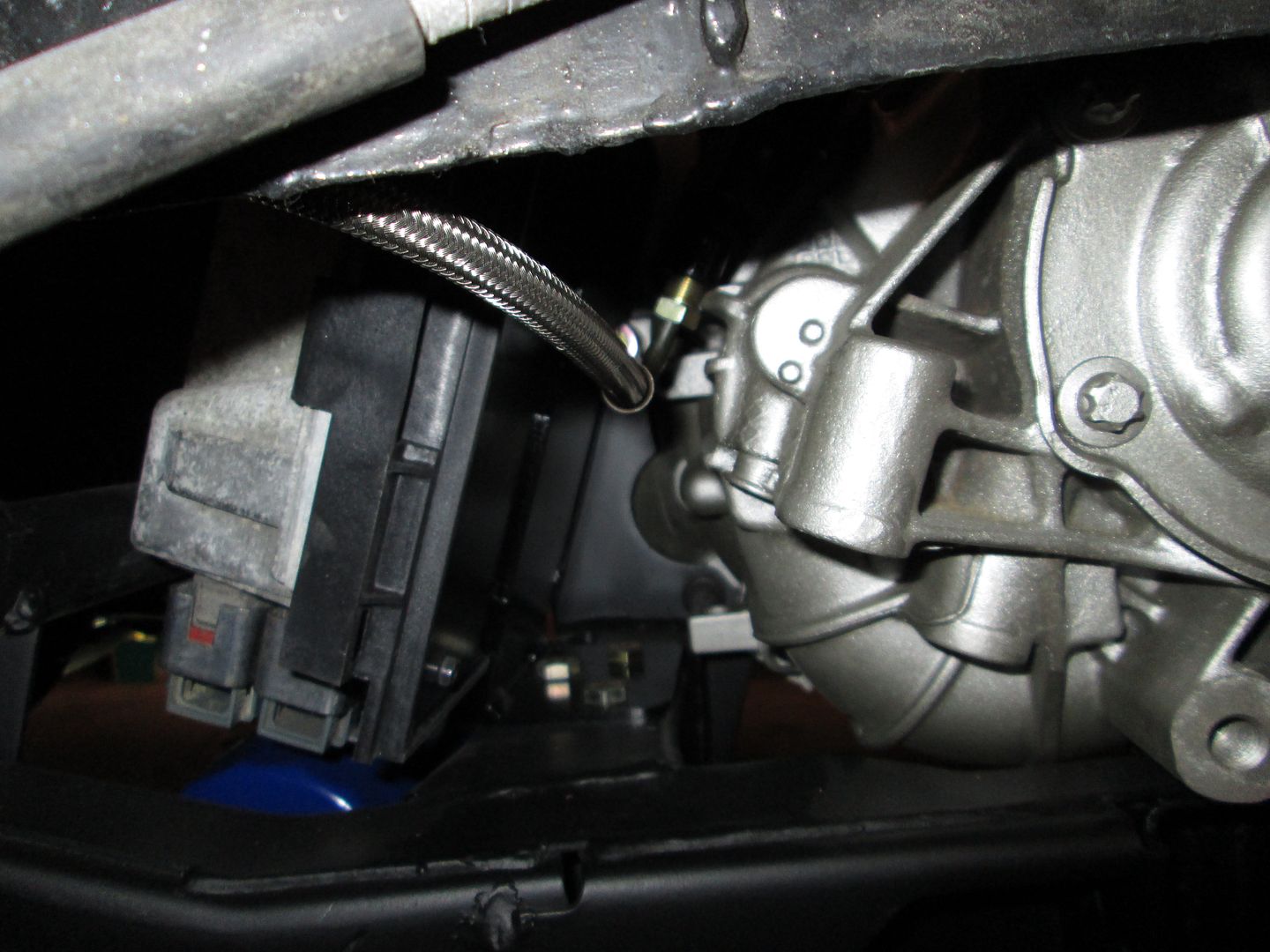
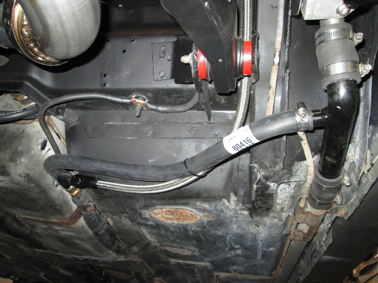
So after a 3 week hiatus, I am back working on this swap again. Nothing glamorous to show for today... Installed the fuel tank, fuel filter, connected the fuel lines, ran the power and ground cables along the fuel tank and soldered on new ends and made the needed connections. Hooked up one of the heater core lines and then installed the clutch line repair section and hooked up the HTOB.
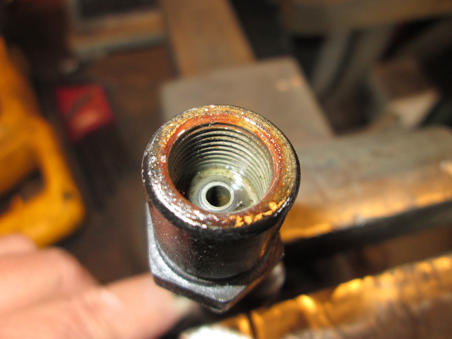
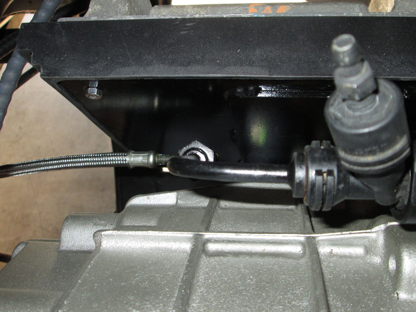
When I got to the clutch line, things slowed down quite a bit. First I noticed the Thelin HTOB clutch line adapter has an inverted flare on the inside instead of the mating side of a bubble flare.
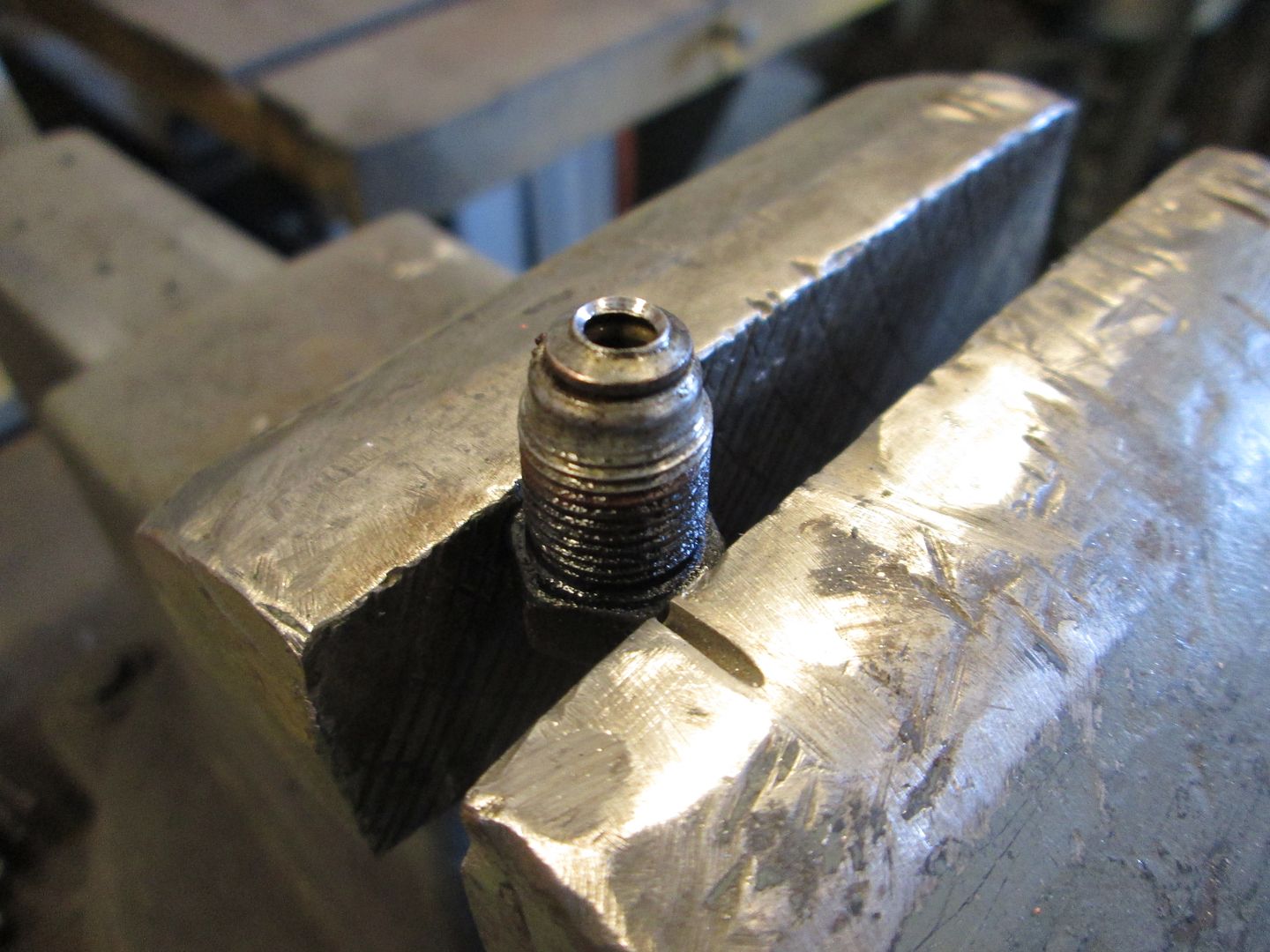
And sure enough on the end of the stock fiero clutch line that I broke off, you can see where the inverted flare was pushing down in the center of the bubble flare.
I have never seen this mentioned in any F23 thread, so I am starting to think that all (or most) of them have been installed with the wrong flare on the end. I used my flare tool to modify the bubble flare to better seal with the inverted flare surface.
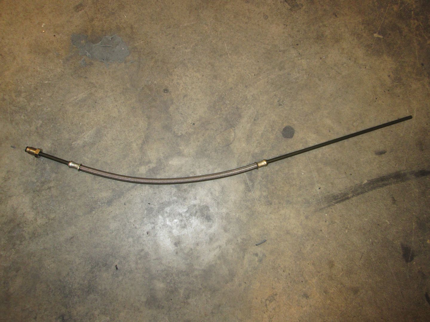
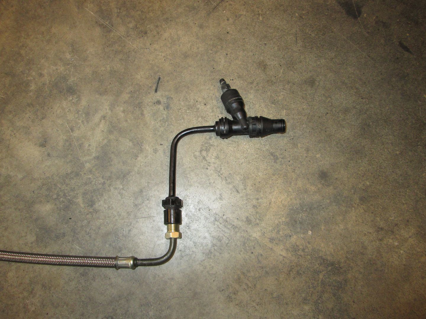
I started with a clutch line repair section from Rodney:
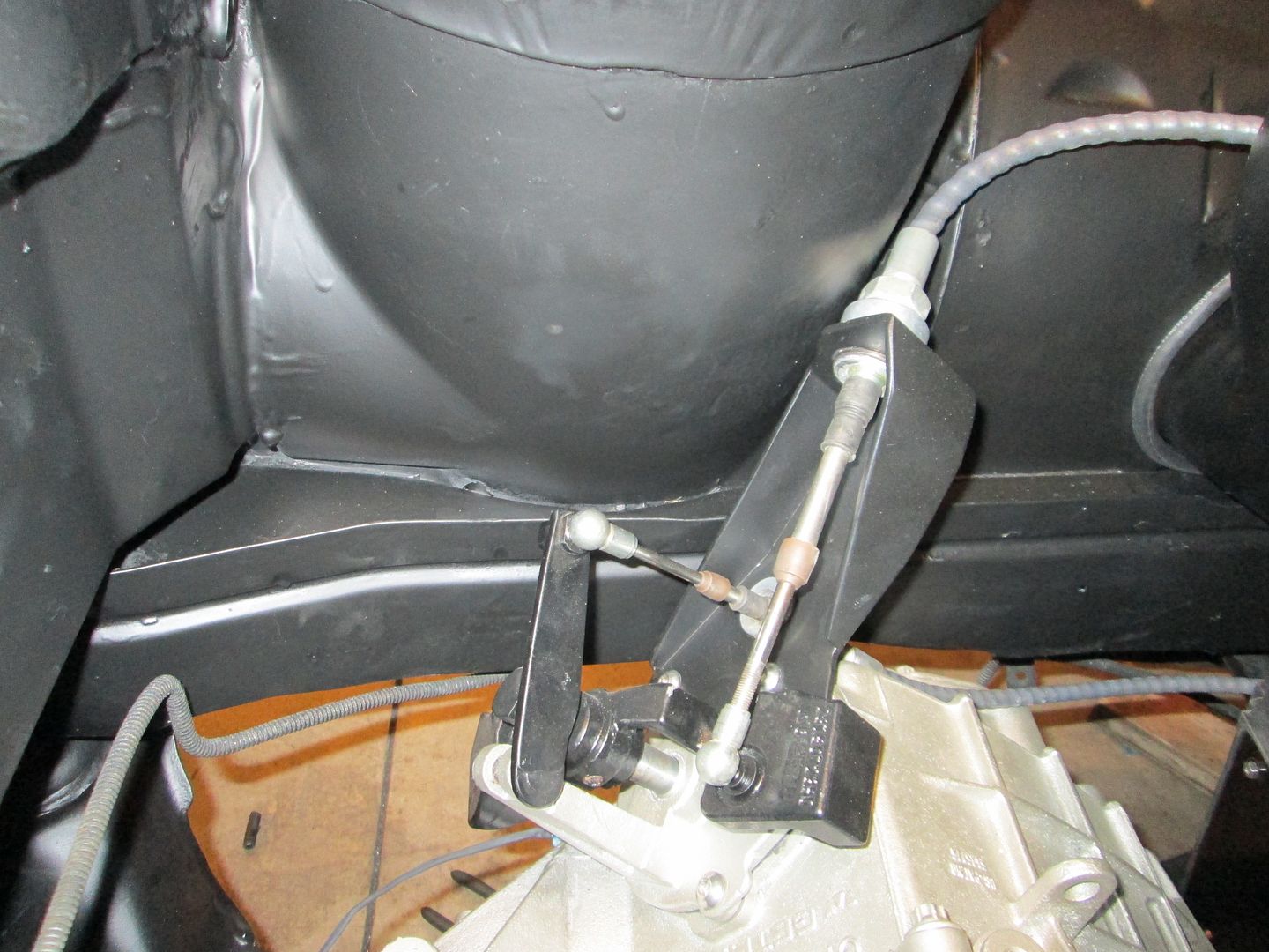
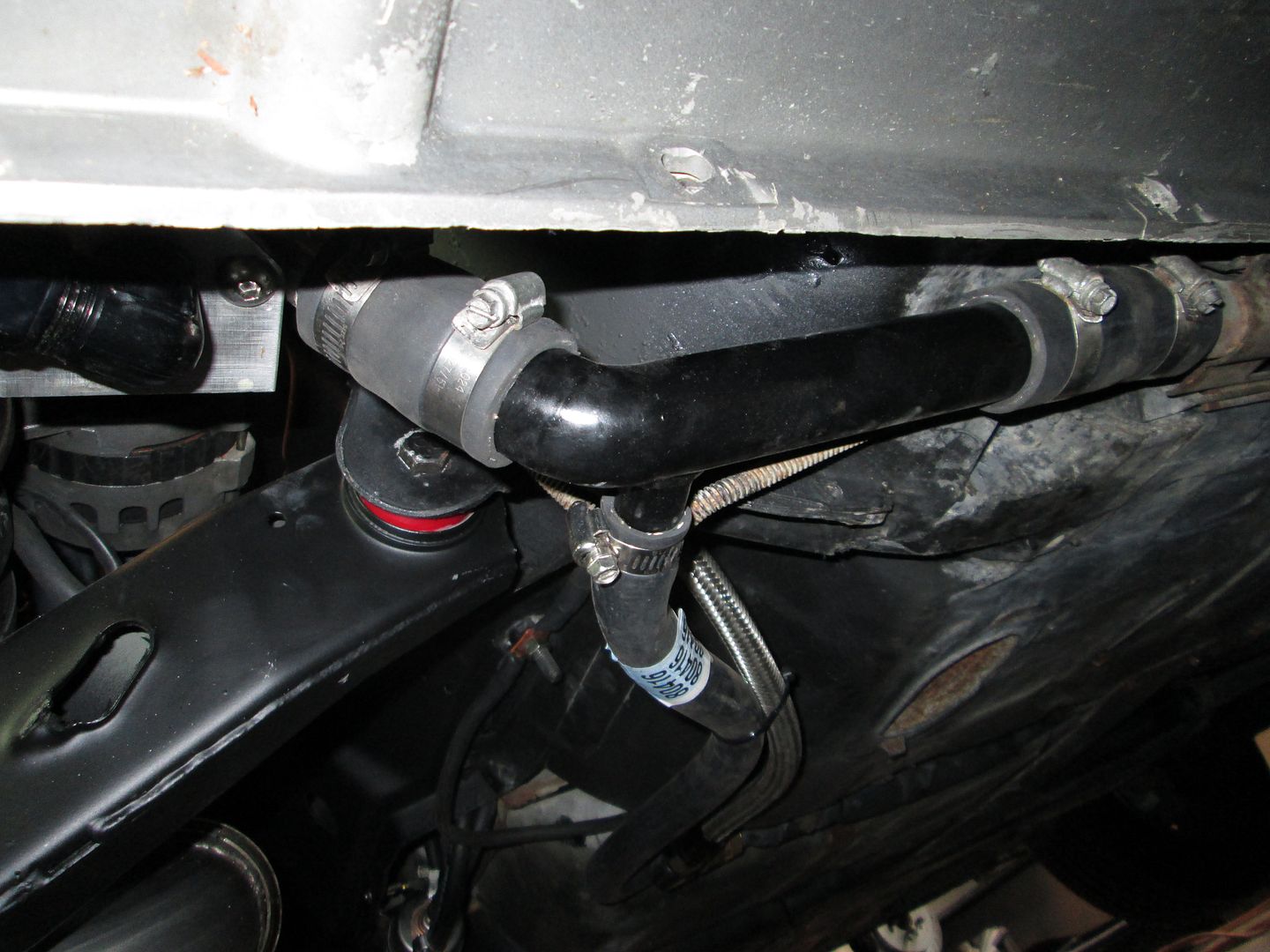
Then I carefully bent the flare end 90 degrees. The Thelin HTOB fitting has the clutch line entering it from the bottom and very low on the cradle, so the clutch line has to go through a bunch of gyrations to attach to it. By adding this simple 90 degree bend, the clutch line just turns 90 from the frame rail and connects to the Thelin adapter:
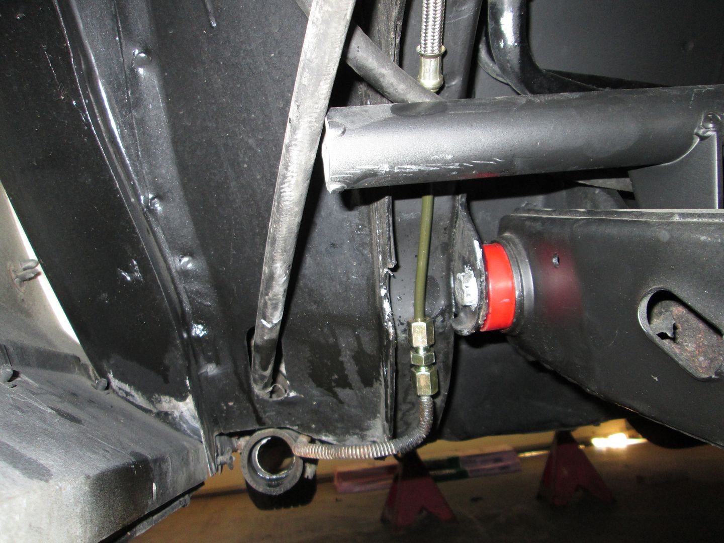
Here is where I spliced the repair line into the stock line. I tried to keep it out of the way of the cradle bolt.
On Sunday I plan to charge up the battery and connect electrical power to the car. Then see if I can get my laptop to connect with the ecm and download the current program to HP tuners and spend a hour or two making a base file with all the changes. Once that is done I will do some more electrical checkouts and might get to the point of turning the key to see if it will start. The coolant system connections and the exhaust tips still have to be finished, so if it starts I will only run it a few seconds.
[This message has been edited by fieroguru (edited 03-15-2014).]
So the fitting that didn't have the right flare - is there an 'off the shelf' part that I should list in the F23 tutorial? Or is modifying it with tools the only solution?
Here's to hoping it kicks over for you without any issues!!
So the fitting that didn't have the right flare - is there an 'off the shelf' part that I should list in the F23 tutorial? Or is modifying it with tools the only solution?
I am likely going to have some fittings made that will fit the HTOB bleeder assy and accept the stock fiero hard line. That will make it plug & play going forward for the F23 and F40 swaps.
When I swapped my Fiero Getrag for one with HTOB, I used Mcleod 139204-xx and cut off the fiero clutch flexline. Then I used 4-AN tube adapater and 4-AN union to attach it to the fiero hardline.
EDITED to Add: The part number I've stated above does not fit! I had purchased the Mcleod line some years ago and I had forgotten that I had to cut off the quick disconnect fitting and used the fitting from a Pontiac Sunfire instead. The Mcleod fitting is longer and will not lock in place.
[This message has been edited by cyrus88 (edited 05-07-2014).]
When I swapped my Fiero Getrag for one with HTOB, I used Mcleod 139204-xx and cut off the fiero clutch flexline. Then I used 4-AN tube adapter and 4-AN union to attach it to the fiero hardline.
Over the years there have been many methods used to connect the Fiero hard line to a HTOB, but they all have all either involved some type of modification to the Fiero hard line, or had the wrong flare... What I am proposing is a single piece that threads to the stock hard line with the proper flare fitting and have the right quick disconnect on the other end to just plug into the F23 or F40... no modification and a simple bolt in installation.
[This message has been edited by fieroguru (edited 03-16-2014).]
Today wasn't as productive as I would have liked, but I did get the battery charged up, soldered on some more cable ends and started to bleed the brakes. Then I got pulled away on other family stuff and finishing up other customer orders.
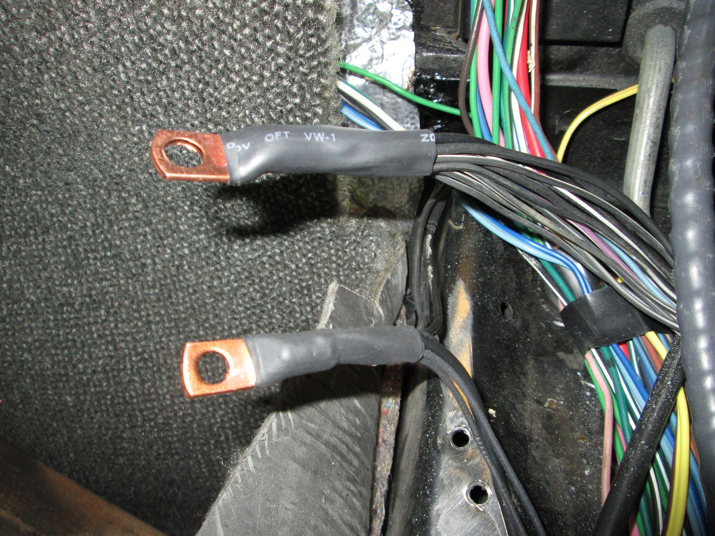
The bottom brass lug are all the grounds in the chassis harness. As I was reworking the chassis side of the 500 harness, there was a large splice section in this area. I removed the splice section and ran all the grounds to this single lug. The lug was heated, filled with solder, the wire group pushed into the lug and brought up to temp to ensure the solder flowed out to all the wires. Then covered in heat shrink. The top larger lug is every engine sensor & ECM ground. It received the same treatment.
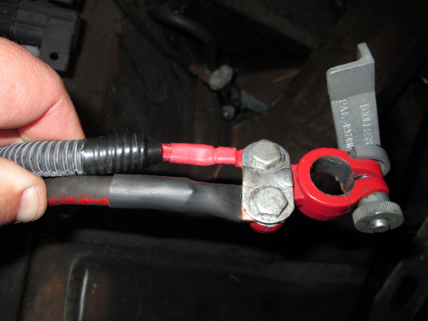
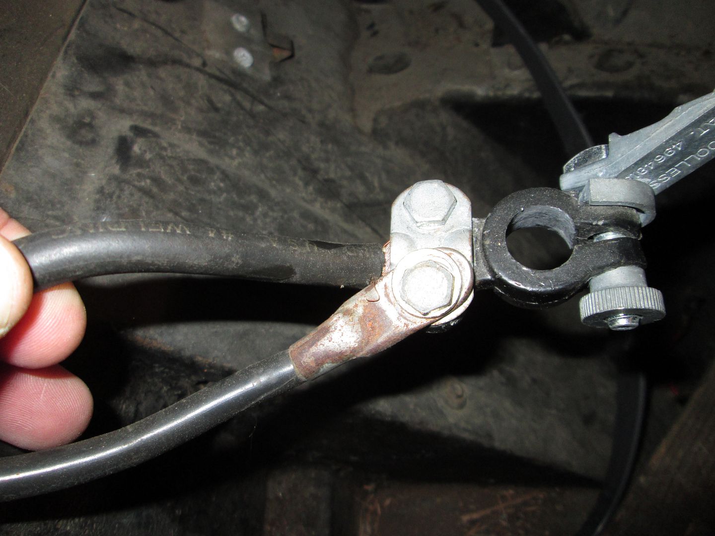
I didn't take a before pic, but lets just say the positive battery cable was showing wires and not well attached using the cable clamp on this connector. So I cut the frayed end back to clean copper and prepped it for another lug. Everyone of these lugs I install gets the same treatment, then bolted the lug to the clamp bolt.
I still need to do a little work on the negative side, but its not as bad as the positive side was.
[This message has been edited by fieroguru (edited 03-16-2014).]
Over the years there have been many methods used to connect the Fiero hard line to a HTOB, but they all have all either involved some type of modification to the Fiero hard line, or had the wrong flare... What I am proposing is a single piece that threads to the stock hard line with the proper flare fitting and have the right quick disconnect on the other end to just plug into the F23 or F40... no modification and a simple bolt in installation.
That's a good aim, but I wanted to change the steel braided line because it wasn't looking so good after 20+ years.
I take full responsibility for the horrible job with putting those quick-disconnect terminals on for the battery. It's a stellar example of why I don't usually do work myself. lol
On Monday I powered up the ecm and was able to copy the stock calibration into HP tuners. Then spent the next couple evenings working on a base tune to get the engine started. Changes were:
Turn off VATS, EGR, AIR, and Torque Management Edit all injector tables for the Bosch 36# injectors. Convert the LS7 MAF table from my car (E67) to the LS1 resolution and load it up. Reduce the VE table by 15% in the idle corner of the table. Also reduced the entire Cranking VE by 15% as well. Did a crude tweak to the IAT table (it was reading 80 degrees when it was 55-60 degrees - IAT sensor was swapped as it is part of the LS7 MAF)
With those tweaks I was able to do this:
Now that I know it will run, I can finish all the odds and ends to get it to the point of idling in the driveway.
I had to give it a little throttle to get it to start and it won't idle on its own yet, so the tune as a long way to go but it... RUNS!
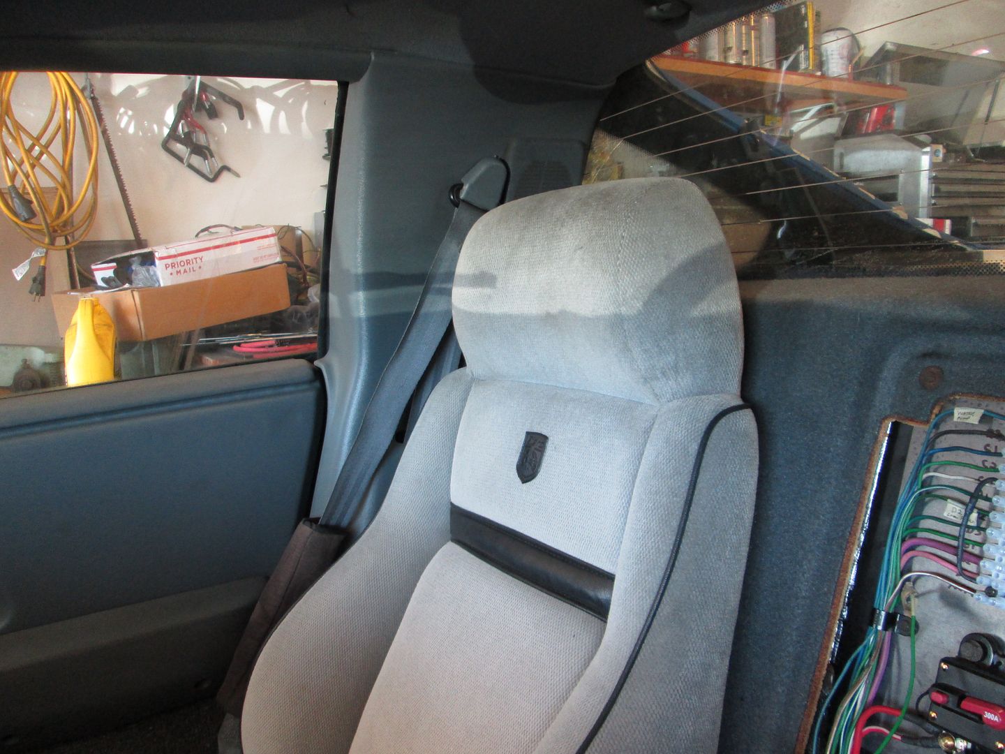
Installed the rear carpet, side interior panels and the seats:
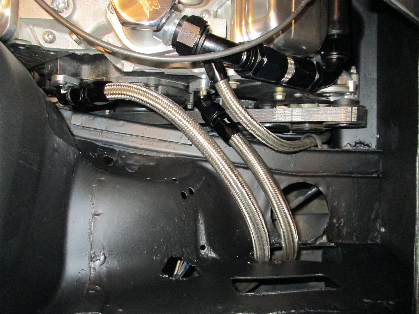
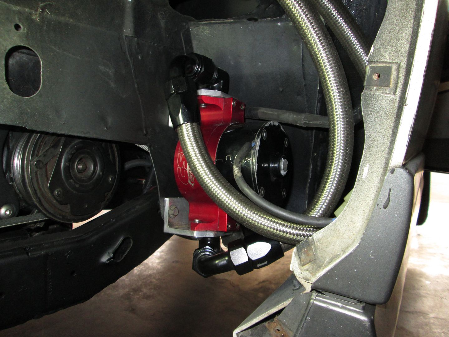
Installed the water pump and connected the AN fittings:
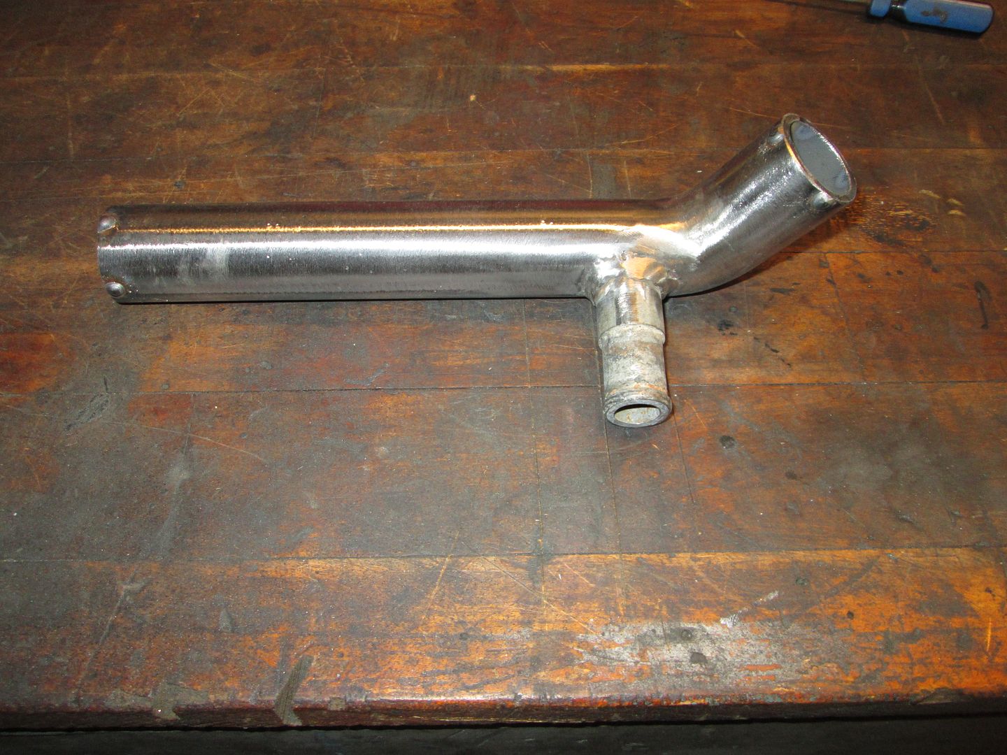
Made this coolant pipe that goes between the passenger side coolant tube and the water pump. It has a nipple for the heater hose to dump into the line before the water pump:
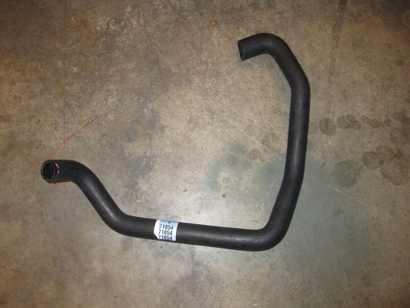
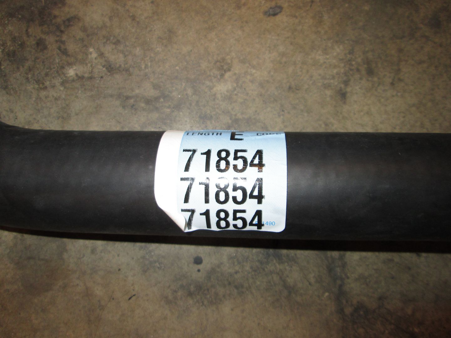
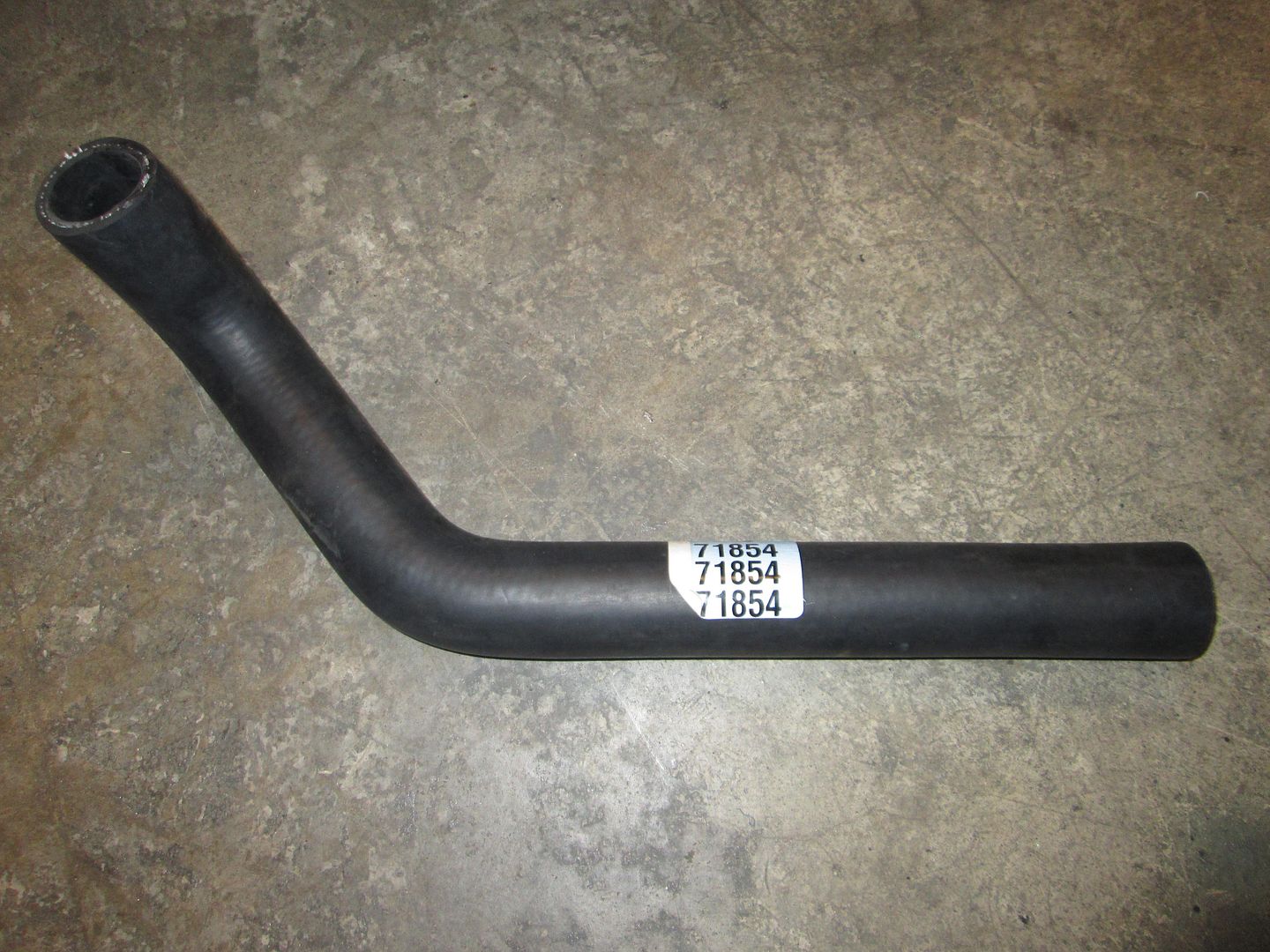
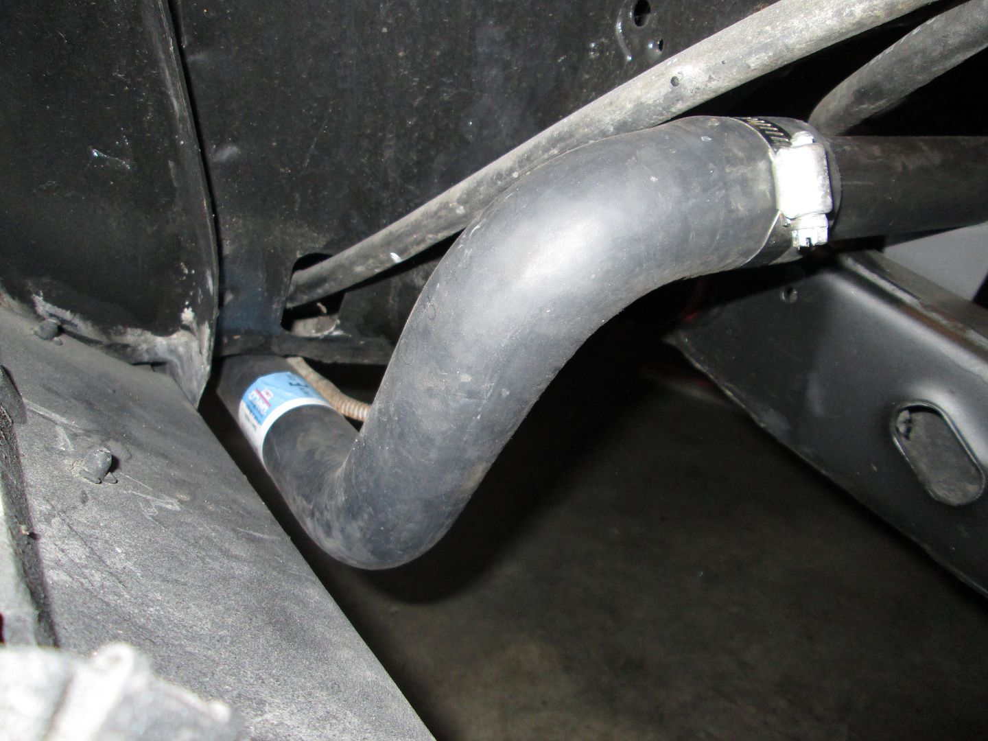
Source the coolant hoses for the heater core and the driver side. Driver side hose:
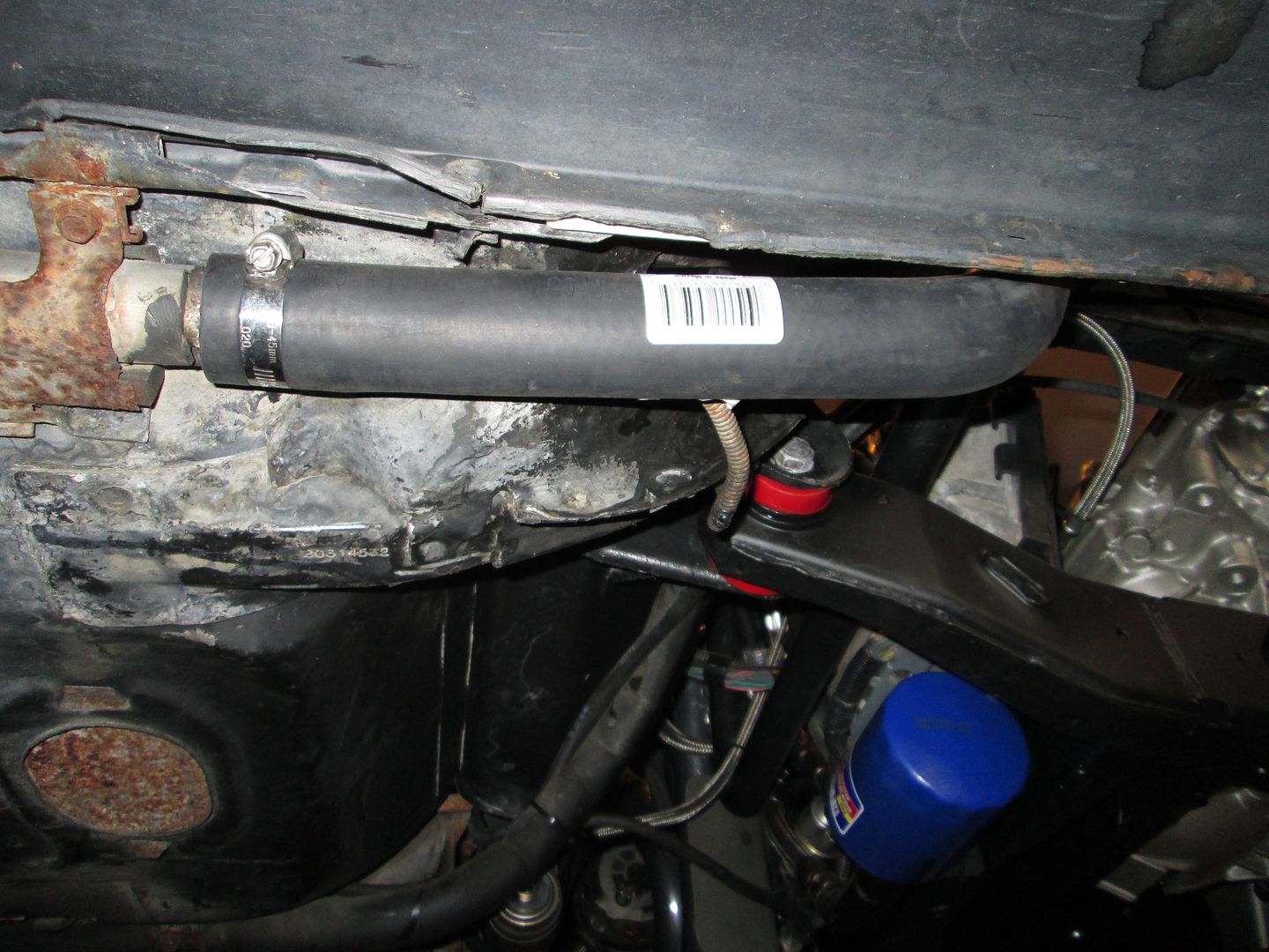
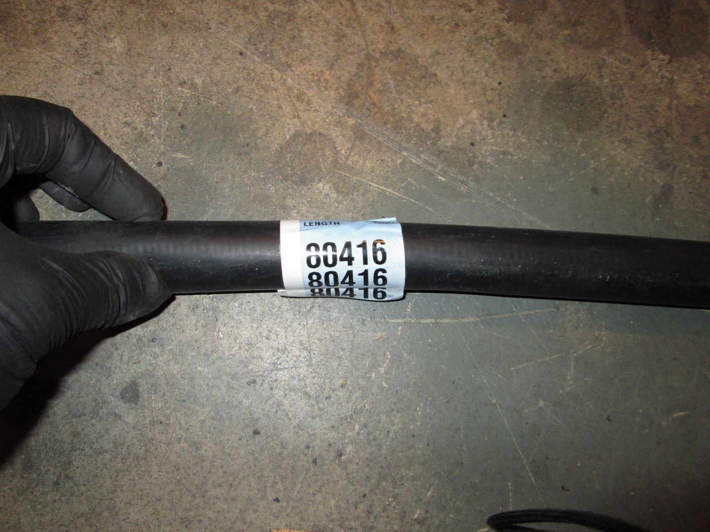
Heater core hose:
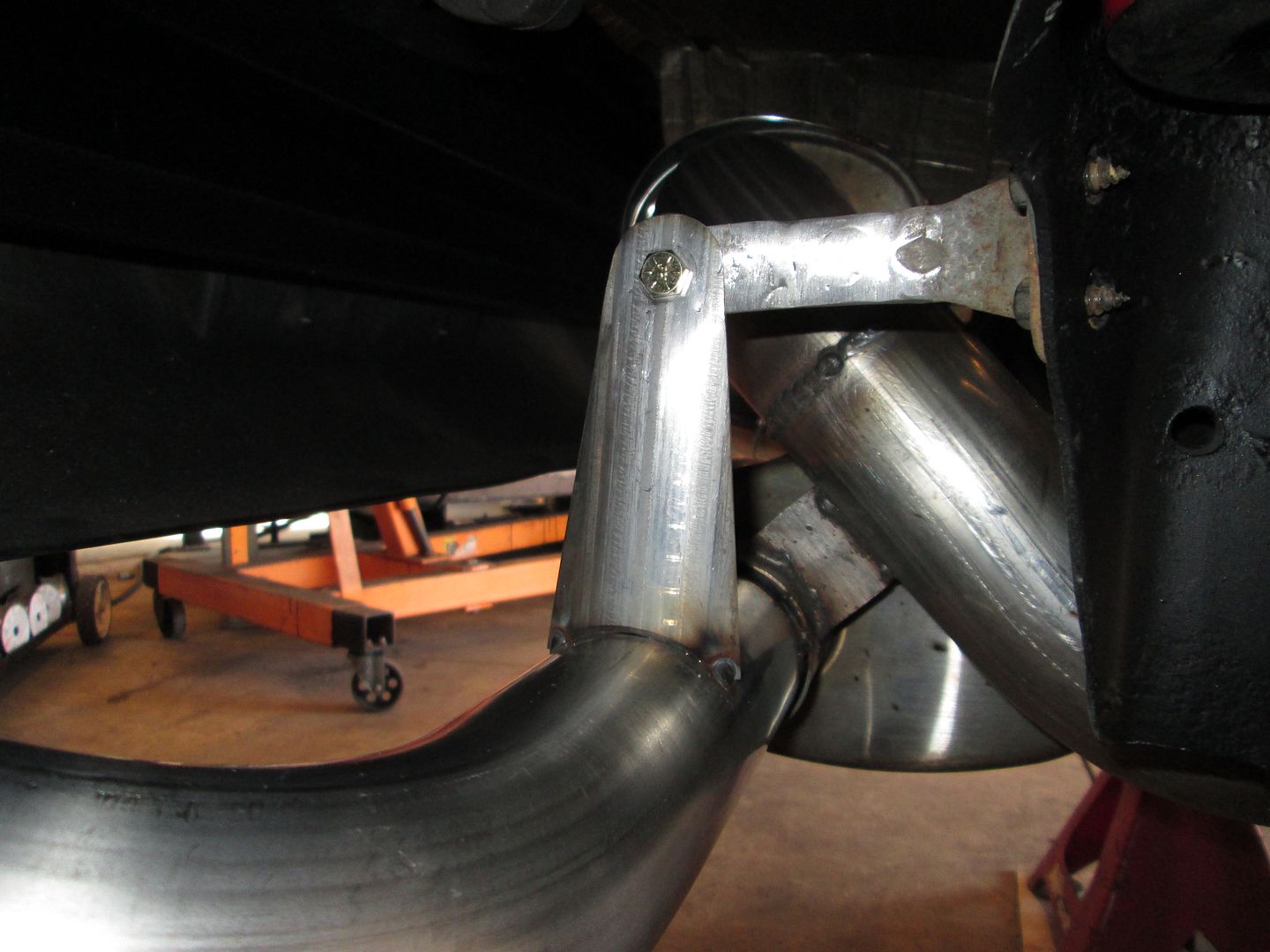
Then tacked together the rest of the exhaust:
Filled the engine and burped the coolant system with 50/50 antifreeze mix.
Sunday I will finish weld the exhaust, put the rear suspension back together and try to get the car sitting on its wheels again.
The exhaust has been fully welded and reinstalled:
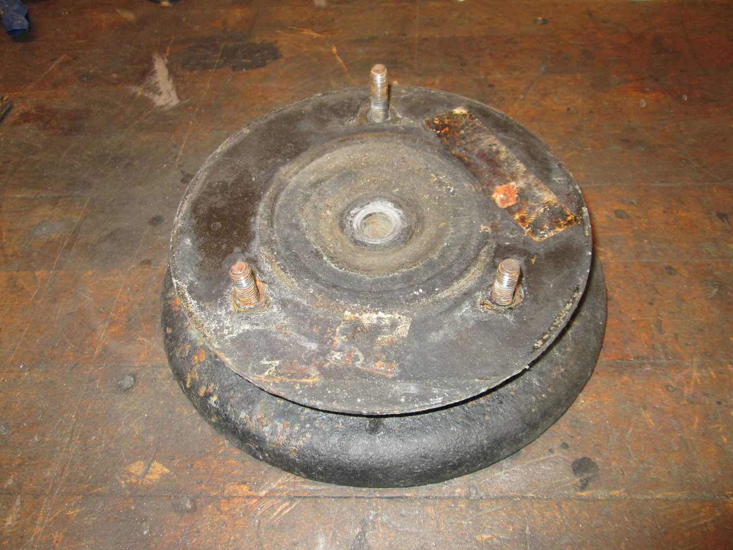
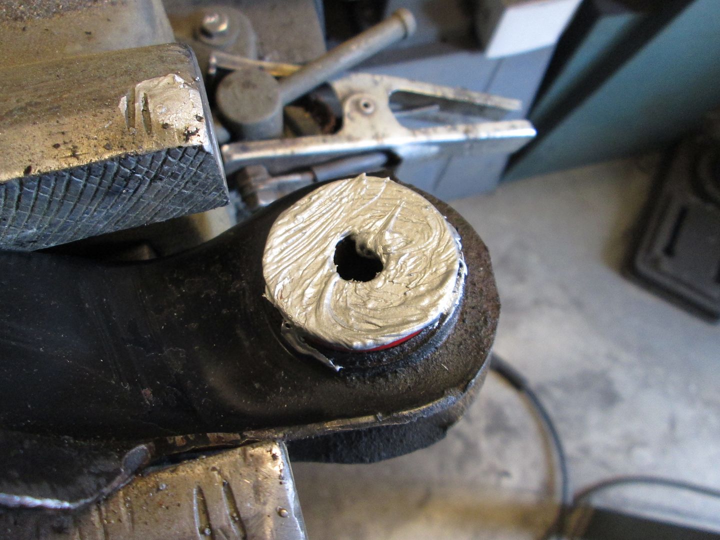
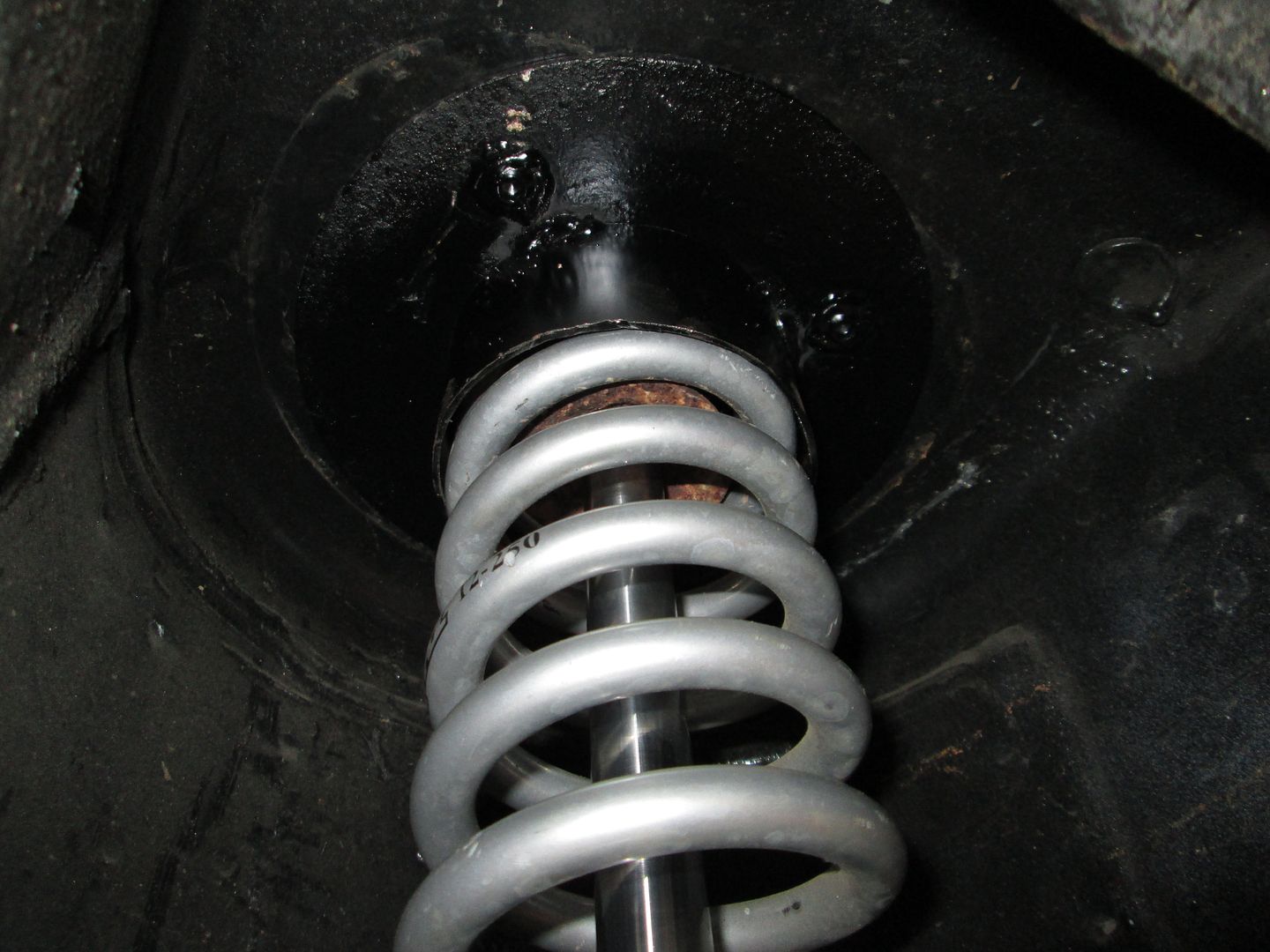
Next, I got started on the rear suspension. The coilovers didn't have upper spring locators and was still using the old upper spring perch for the studs, so I fixed both of those. This is what came out:
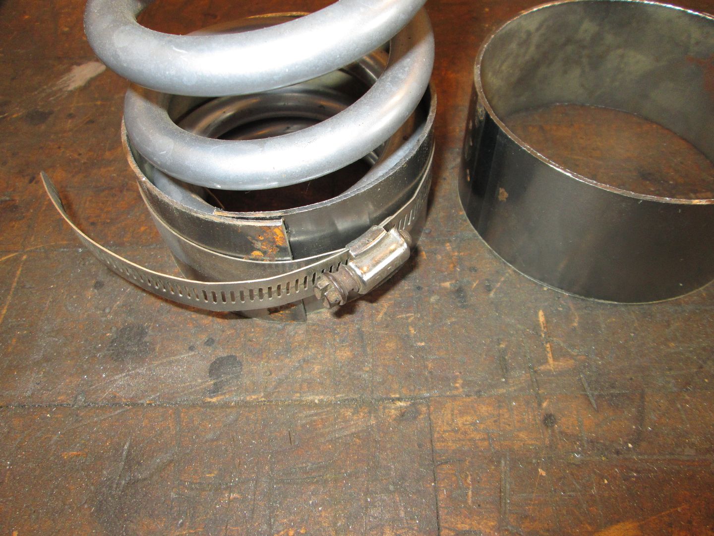
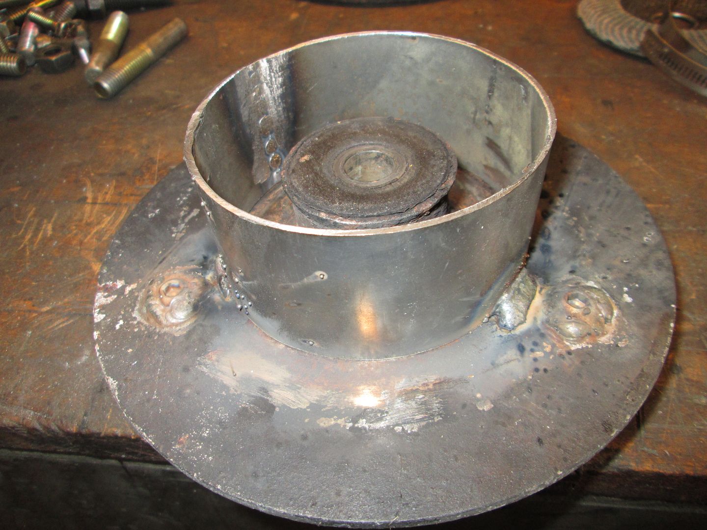
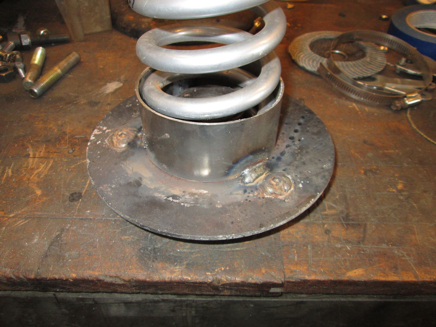
The bushing plate doesn't have studs, so I welded some stainless steel metric bolts to it for studs. Then took some 4" exhaust pipe, cut a slit into it so I could use a hose clamp and reduce the diameter to be within 1/8" of the spring OD. Then I cut the excess off, welded the seam closed, and welded the tube to the strut bushing plate:
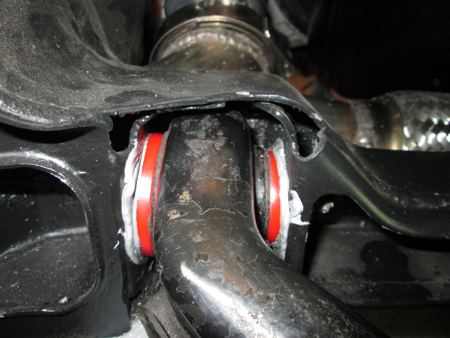
The lower a-arms had poly bushings in them already, so I removed the sleeves and coated everything with anti-seize:
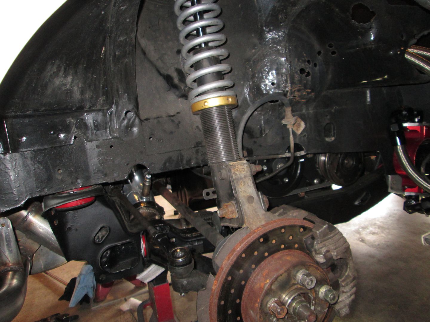
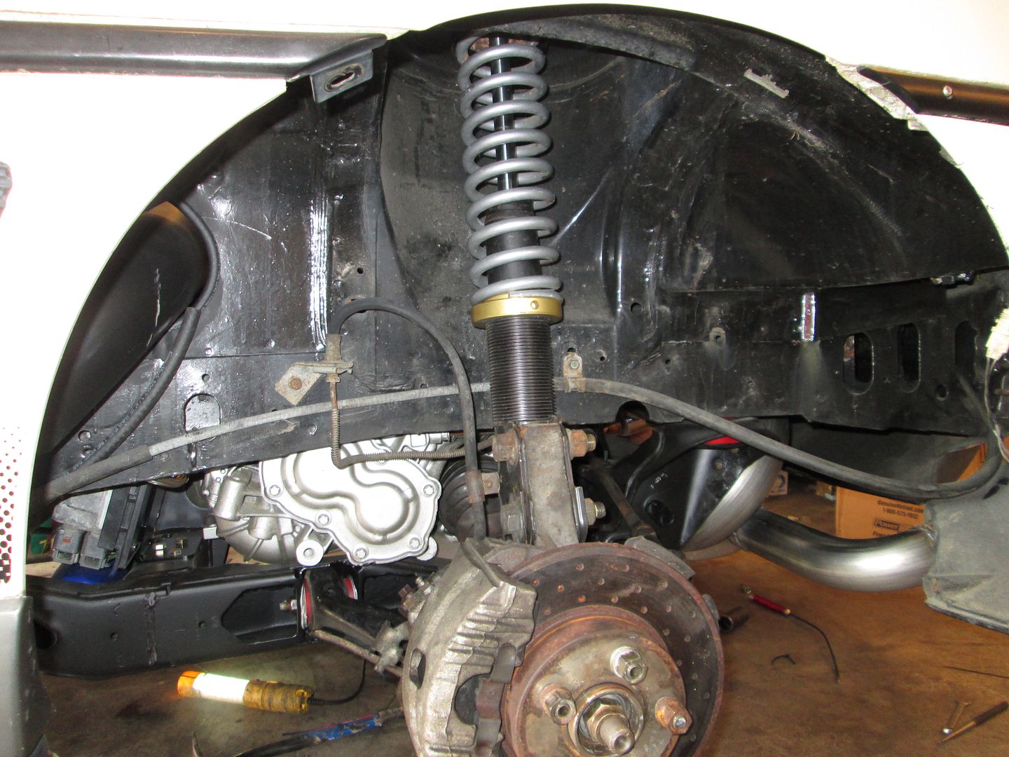
The rear suspension is now back together and the brake calipers are installed. I ordered another camber bolt for the rear struts and will align the rear before I put wheels on it, but that will be Tuesday or Wednesday at the earliest. I still need to install the rear sway bar and the parking brake cables and bleed the brakes.
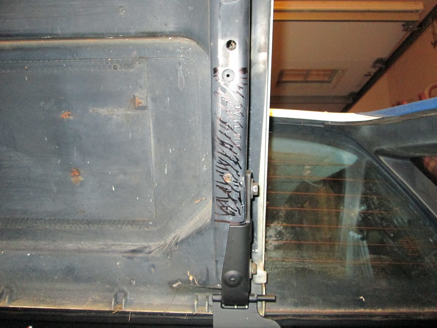
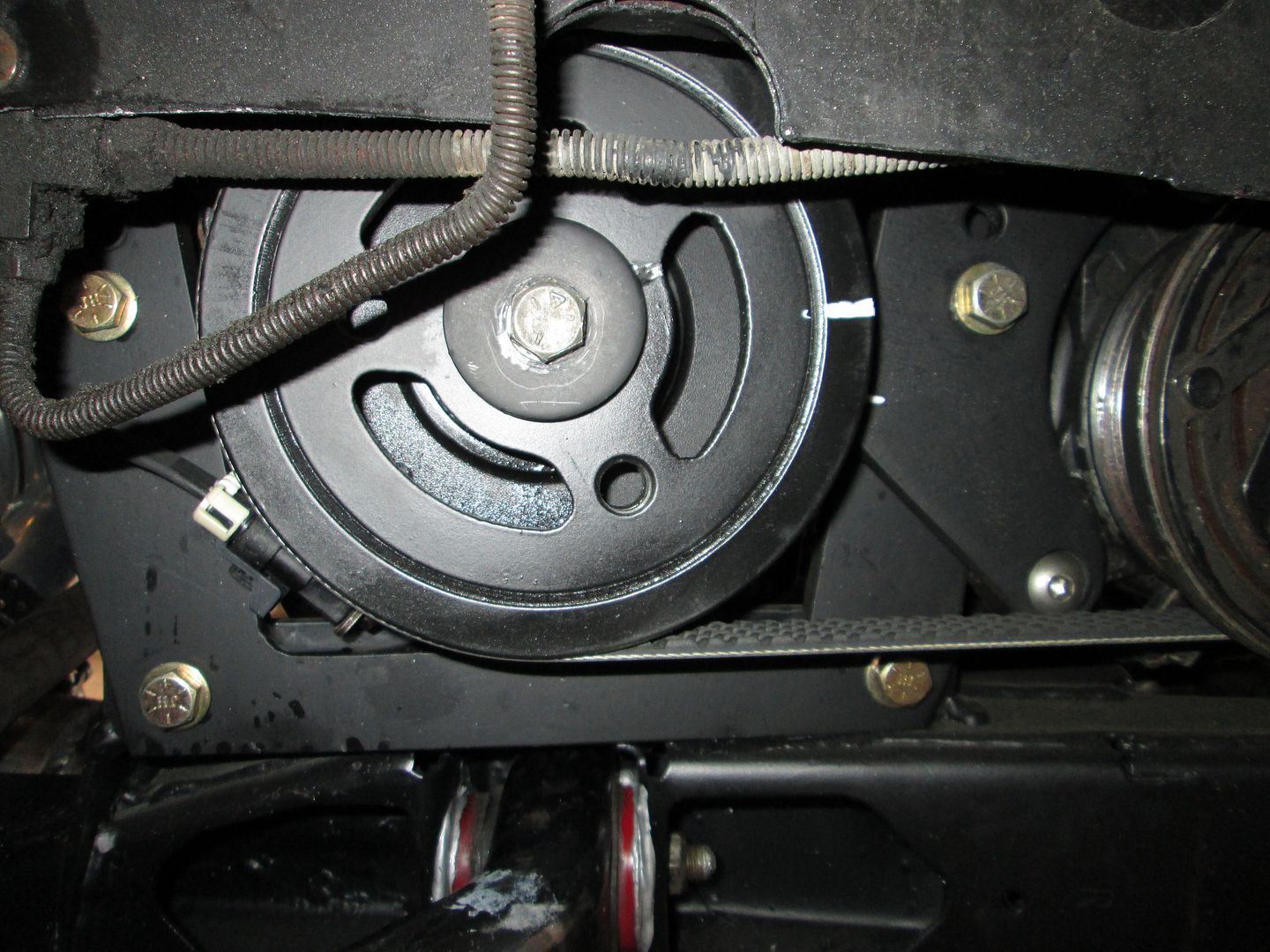
Since I changed the firing order with the ECM, I want to make sure every cylinder is firing when it should. I added this large (more visible) white line on the outer edge of the balancer inline with the TDC mark on the backside. I can use my timing light on each spark plug wire and note where the white mark is when it flashes. Cylinders 1 & 6 should be about 3 o'clock Cylinders 8 & 5 should be about 6 o'clock Cylinders 4 & 7 should be about 9 o'clock Cylinders 3 & 2 should be about 12 o'clock
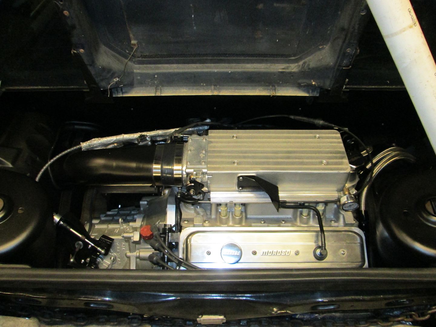
Here is the engine bay with the struts in place:
[This message has been edited by fieroguru (edited 03-23-2014).]
I have been updating Vince through PM's as I am working through some issues.
I have put about 20 miles on the car and have done 3 rounds of logging/adjusting in the lower levels of the MAF and VE tables to dial them in pretty decent. I haven't started the WOT tuning yet. The car has a lot more low end torque than my LS4 swap and the throttle response is a huge improvement from when it was carbed.
Been working on several small issues...leaky v-band, bad brand new idler pulley, passenger side rear caliper sprung a leak at the parking brake lever, bad clutch master cylinder.
The three more significant issues are: 1: Transmission (filled with syncromesh) gear whine in the upper 3 gears that wans't present before. It originally had a resonant vibration at highway speeds in 5th and during the tear down I found that the transmission was missing 1 dowel pin so the transmission wasn't properly centered. It now has 2 dowel pins, and the resonance is gone, but now there is gear whine. The transmission was running Royal Purple ATF, so I am planning to swap that in and see if that helps the whine.
2: The ClutchNet Clutch is super, super light pedal pressure to release. I am concerned about its ability to hold the power. It had a ClutchNet Clutch before and this is supposed to be the exact same clutch. I remember it being lighter than the one in the LS4/F40, but this is really light. I won't know how it does till I do some WOT runs.
3. There is a strange noise from the top side of the engine and I am looking at several items for potential causes.
[This message has been edited by fieroguru (edited 04-06-2014).]
FieroGuru gave me a suggestion in PM, I'm going to explore that, and I was thinking maybe there's some way to fabricate a metal strap that can strap down over the top and provide pressure... it would take away from the super clean look, but it would be a functional solution.
I was also thinking that maybe I can put soft rubber bumpers on the underside of the decklid, so when it's closed it would give some light downward pressure on the intake that wouldn't be a threat to damage either the decklid or the intake.
All else fails, FieroGuru suggested I look for an unmodified HSR upper intake. The lower part of the intake has been chopped down as well (if I remember correctly), so I'd need to keep that to keep it all under the Fiero decklid.
Worst case scenario.... I get some measurements of a F.I.R.S.T. intake, and see if it'll fit and see about getting that put in there.
could always have a fabricator make a sheet metal plenum.