Pennock's Fiero Forum
  The Construction Zone
  Trinten's SBC/F23 build - The work has begun! (Page 7)

Post New Topic  Post A Reply
Email This Page to Someone! | Printable Version | Print VBook

This topic is 18 pages long:  1   2   3   4   5   6   7   8   9   10   11   12   13   14   15   16   17   18 
Previous Page | Next Page
next newest topic | next oldest topic
Trinten's SBC/F23 build - The work has begun! by Trinten
Started on: 08-17-2009 10:48 PM
Replies: 683 (31564 views)
Last post by: Trinten on 04-22-2024 09:26 PM
fieroguru
Member
Posts: 12128
From: Champaign, IL
Registered: Aug 2003


Feedback score:    (45)
Leave feedback


Total ratings: 258
Rate this member

Report this Post11-21-2013 08:01 PM Click Here to See the Profile for fieroguruSend a Private Message to fieroguruEdit/Delete MessageReply w/QuoteDirect Link to This Post
 
quote
Originally posted by ericjon262:

I've always hated adapter plate swaps(mainly because most seem like hack swaps.), but I do love seeing the ingenuity that has gone into this build. keep up the good work.


Thanks! I like for my swaps to have a little creative flair!

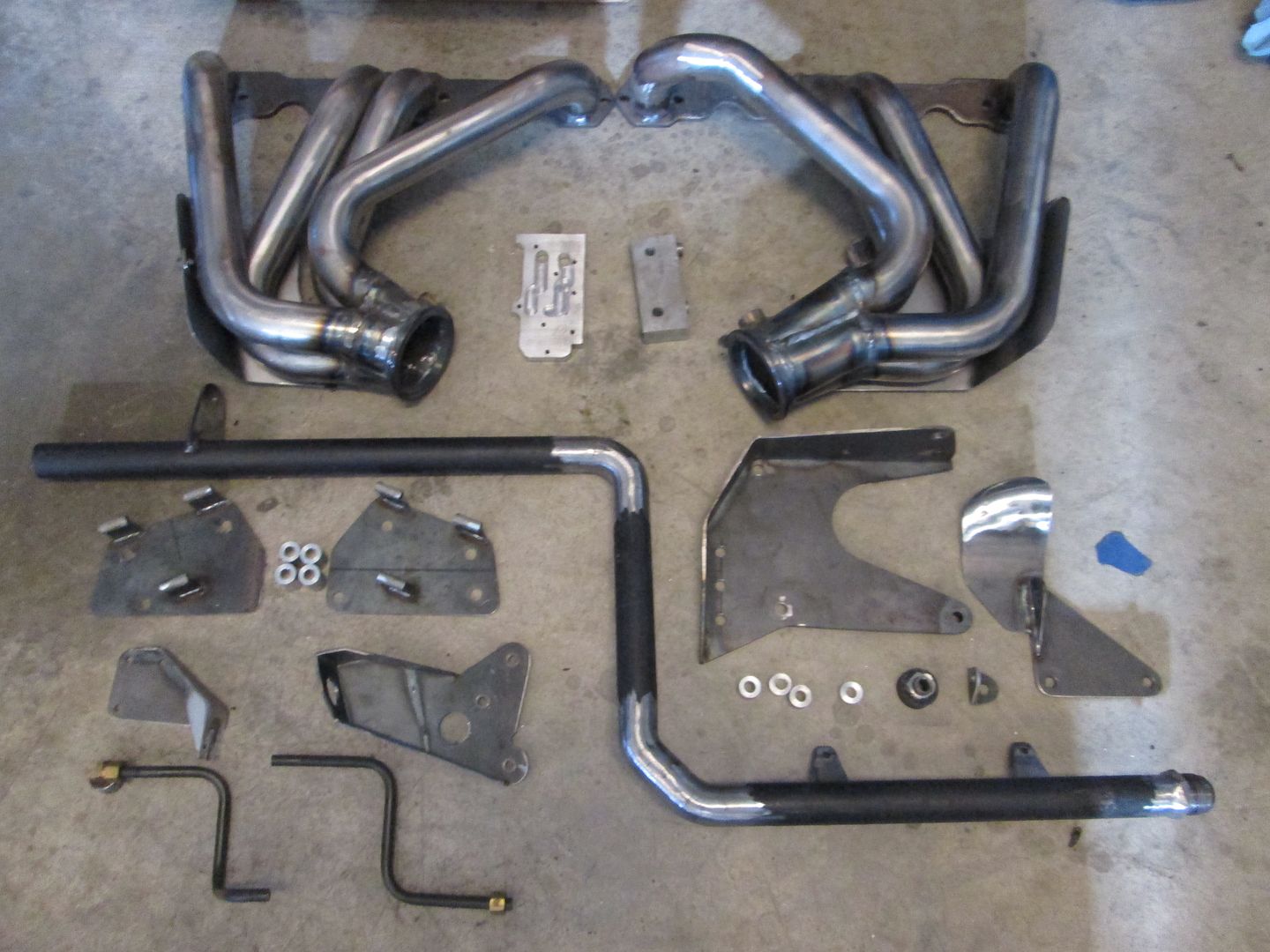
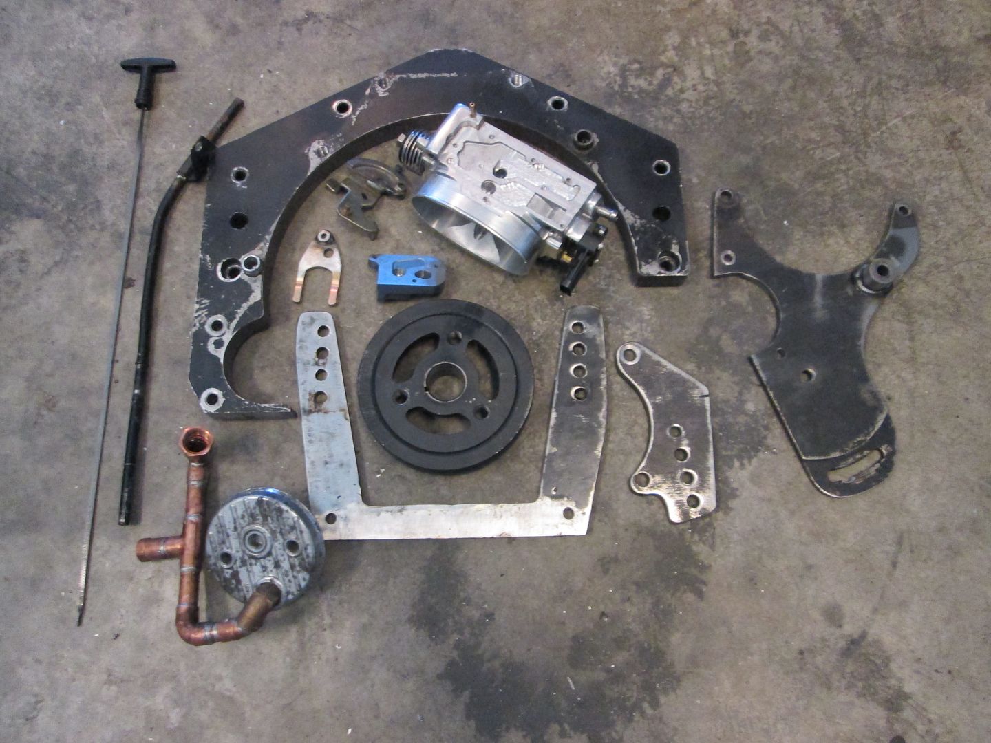
Some aspects of this swap are very similar to the last SBC I did (like the serpentine belt conversion, the thermostat housing to rigid pipe plumbing, the A/N adapters for the water pump ports on the block, the used of sheet metal heat shields, etc). Other aspects are very similar to my LS4 swap (coil packs, 4" cold air intake and use of the LS7 MAF sensor), then there are many other items with unique solutions just for this swap (F23 mounts, F23 shifter bracket, cradle mods to lower the drive train, IAC relocation, throttle cable bracket, hard lines for PCV, the headers, etc).

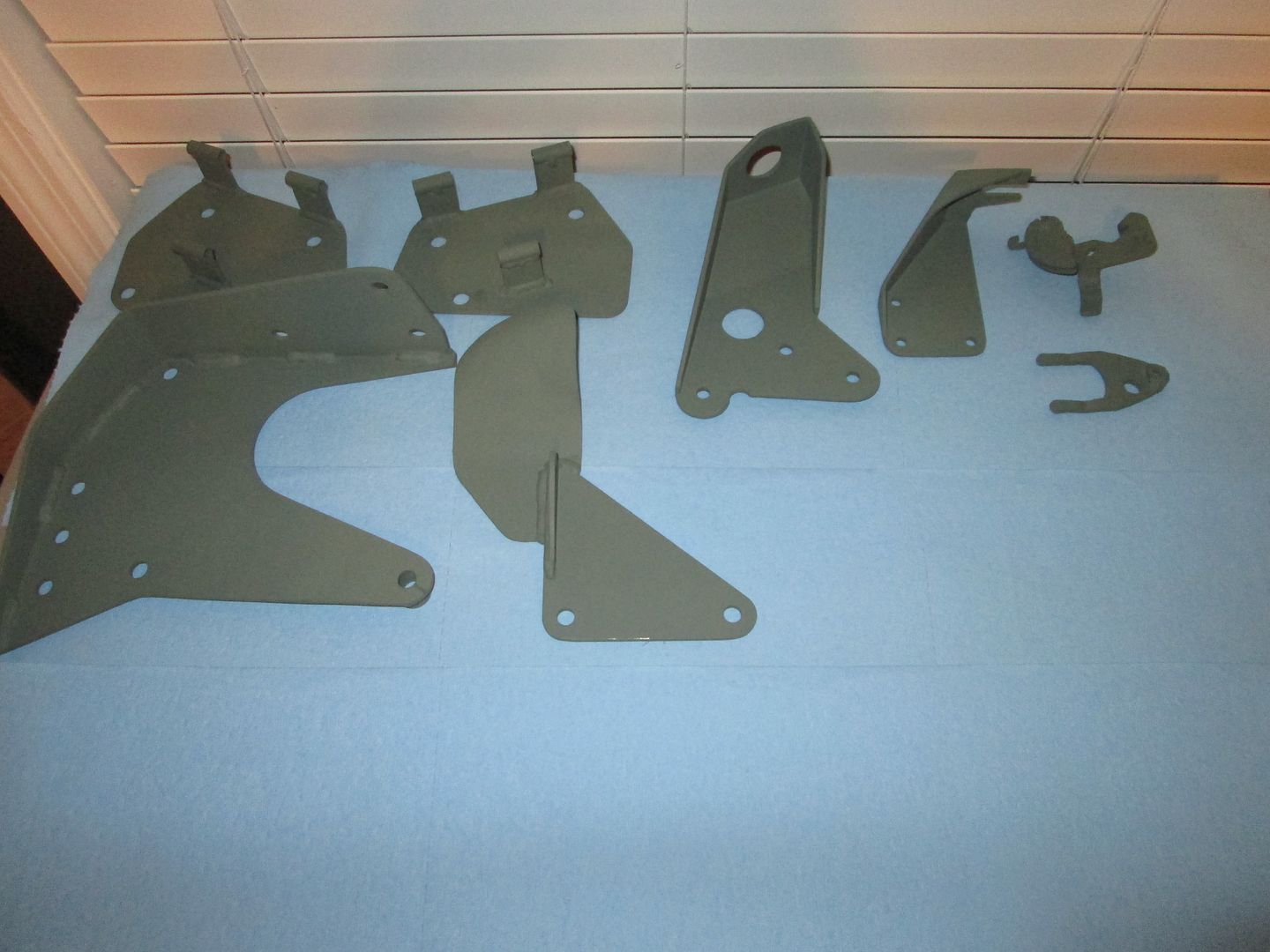
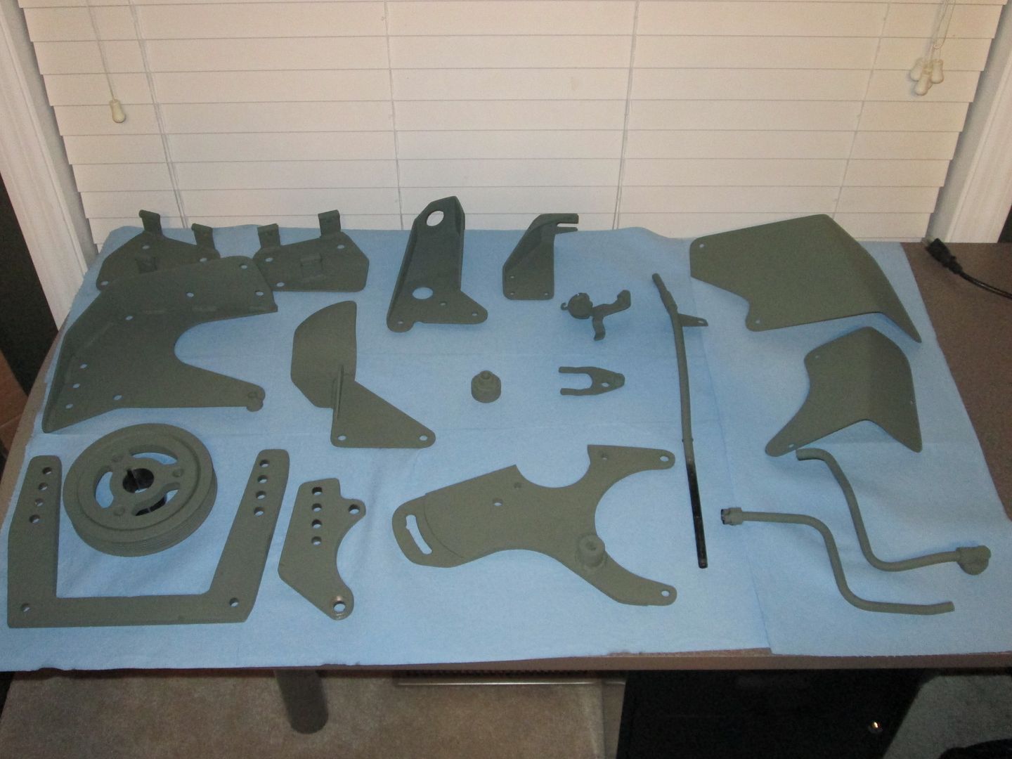
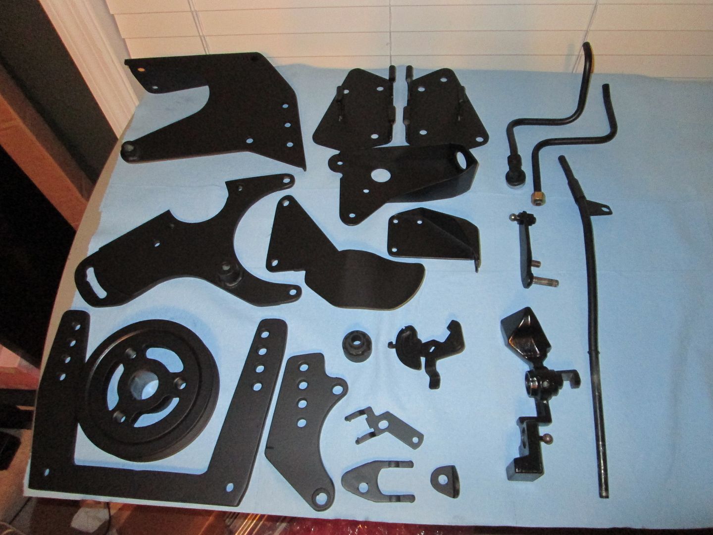
Hopefully over the weekend I will be able to take a picture of all the pieces I made or significantly modified for this swap, just to give an indication of the work that has been put into it.

The O2 sensor bungs came in today, so I will try to have the headers complete Friday and should be able to ship them to the coaters early next week.
IP: Logged
fieroguru
Member
Posts: 12128
From: Champaign, IL
Registered: Aug 2003


Feedback score:    (45)
Leave feedback


Total ratings: 258
Rate this member

Report this Post11-23-2013 02:08 PM Click Here to See the Profile for fieroguruSend a Private Message to fieroguruEdit/Delete MessageReply w/QuoteDirect Link to This Post
Welded the o2 sensor bungs to the headers:


Then I started taking everything apart. The engine is back on the stand:


Transmission hanging out on the floor:


Here is everything I fabricated for the swap (except the engine and transmission brackets that are welded to the cradle):


Here is everything that I have modified in some manner (throttle cable and the fittings for the water pump ports on the engine not shown):


IP: Logged
fieroguru
Member
Posts: 12128
From: Champaign, IL
Registered: Aug 2003


Feedback score:    (45)
Leave feedback


Total ratings: 258
Rate this member

Report this Post11-24-2013 07:56 PM Click Here to See the Profile for fieroguruSend a Private Message to fieroguruEdit/Delete MessageReply w/QuoteDirect Link to This Post
Just been sanding, cleaning and priming...


Several more parts are still drying.
IP: Logged
fieroguru
Member
Posts: 12128
From: Champaign, IL
Registered: Aug 2003


Feedback score:    (45)
Leave feedback


Total ratings: 258
Rate this member

Report this Post11-25-2013 08:10 PM Click Here to See the Profile for fieroguruSend a Private Message to fieroguruEdit/Delete MessageReply w/QuoteDirect Link to This Post
The stack of primed parts is getting larger:


The headers boxed up and shipping them to the coaters on Tuesday.
IP: Logged
CowsPatoot
Member
Posts: 2792
From: Skidway Lake, MI
Registered: May 2007


Feedback score:    (29)
Leave feedback


Total ratings: 84
Rate this member

Report this Post11-28-2013 08:05 PM Click Here to See the Profile for CowsPatootClick Here to visit CowsPatoot's HomePageSend a Private Message to CowsPatootEdit/Delete MessageReply w/QuoteDirect Link to This Post
I jumped in to complain about the lack of updates and discovered it was moved to the construction zone.

The fact that the passenger side axle still hasn't been removed kind of bothers me. Is that an issue that should be dealt with while everything is apart? Or just wait till it breaks and assume the worst?
IP: Logged
fieroguru
Member
Posts: 12128
From: Champaign, IL
Registered: Aug 2003


Feedback score:    (45)
Leave feedback


Total ratings: 258
Rate this member

Report this Post11-29-2013 01:30 PM Click Here to See the Profile for fieroguruSend a Private Message to fieroguruEdit/Delete MessageReply w/QuoteDirect Link to This Post
 
quote
Originally posted by CowsPatoot:
The fact that the passenger side axle still hasn't been removed kind of bothers me.


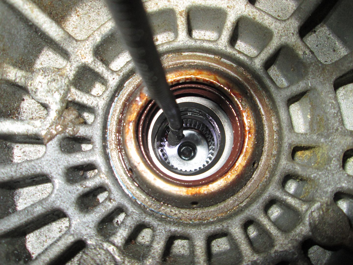
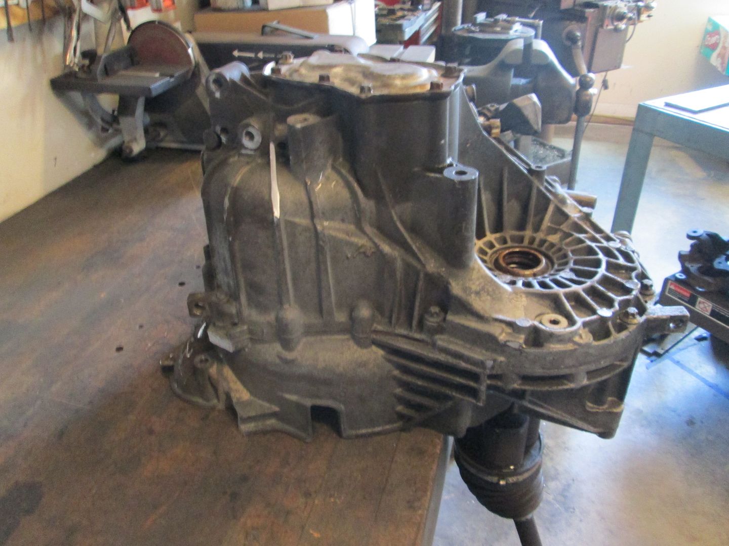
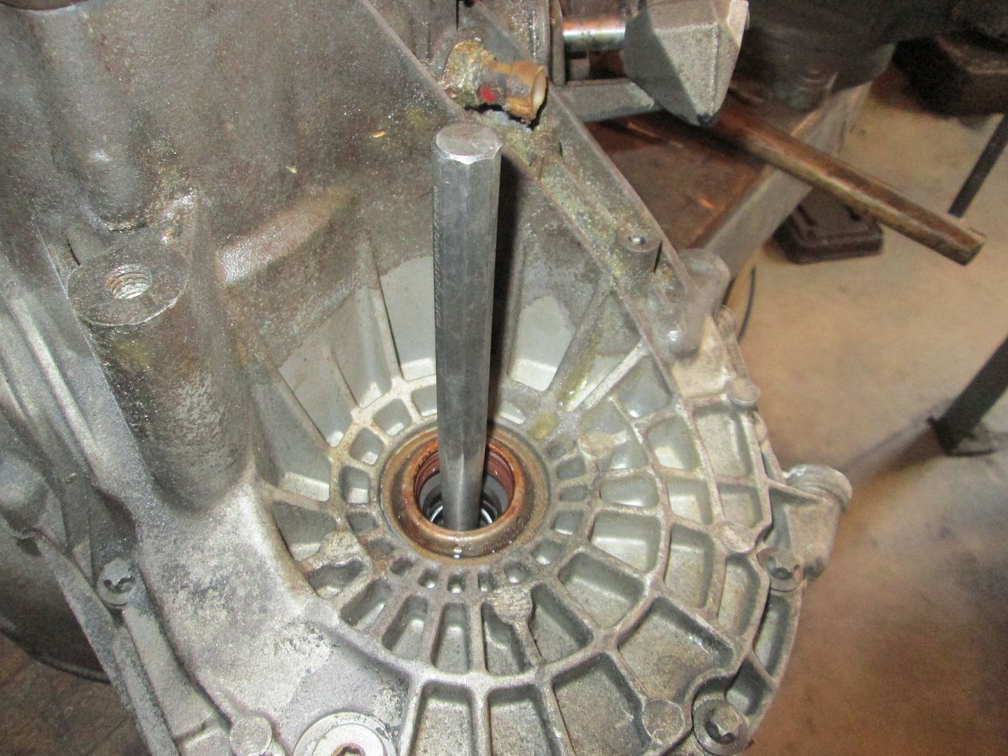
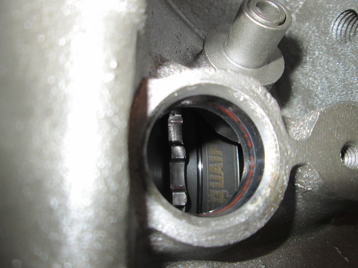
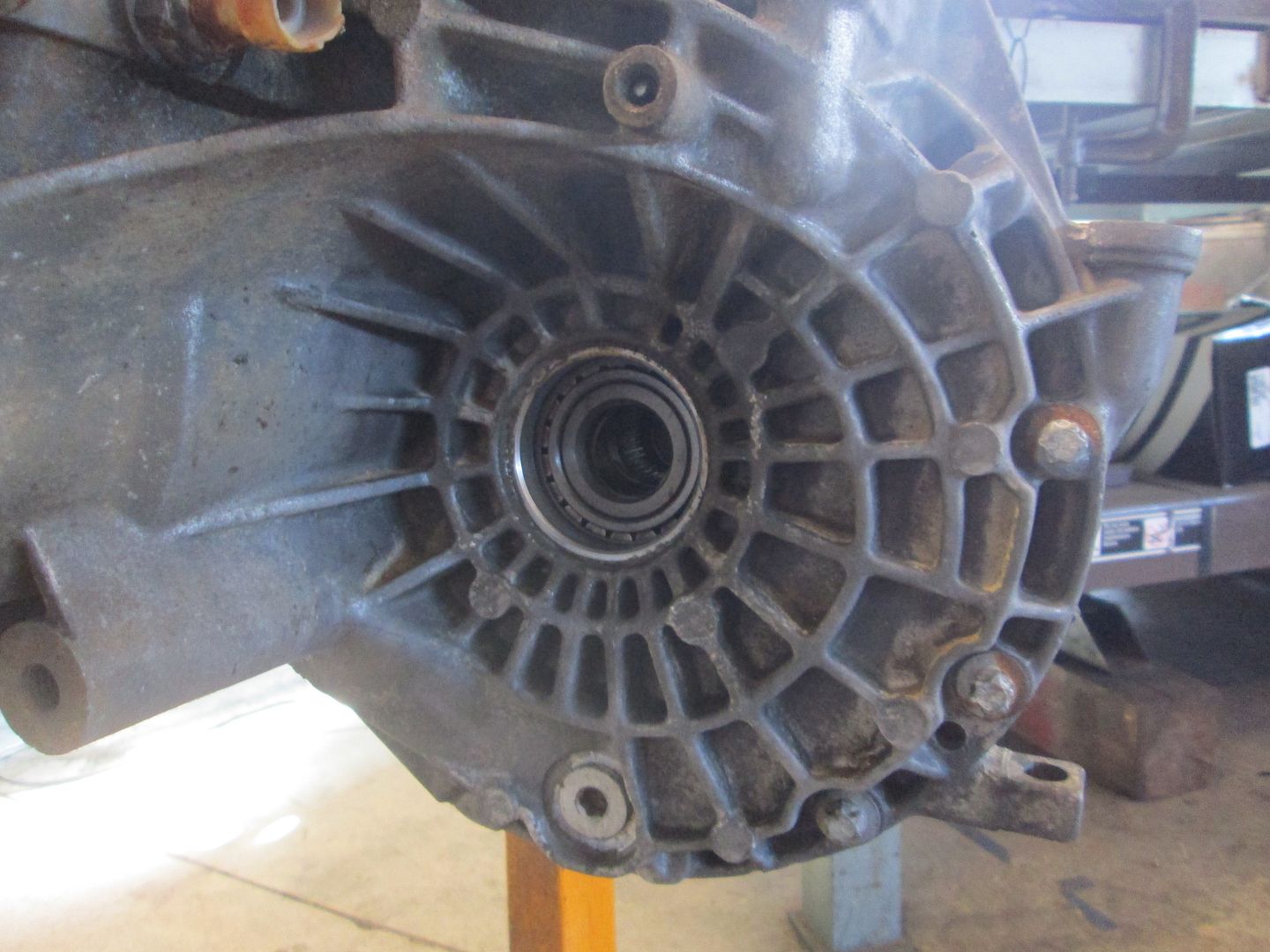
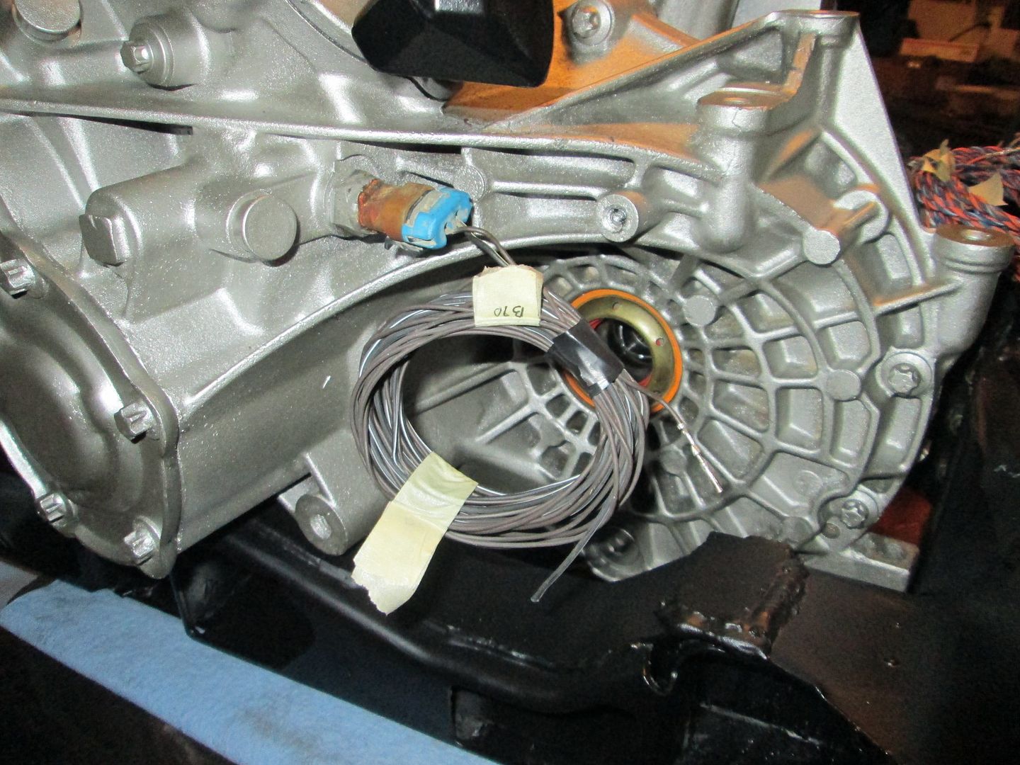
It had tried several times over the course of the built to remove the axle and discussed the issue with Vince. He didn't want me to break the transmission getting the axle out, and it wasn't too much of an inconvenience keeping it in, so I stopped messing with it, and just worked around it. While I had the transmission on the bench taking apart the shifter arms, I looked down the other side of the differential expecting to see a cross shaft blocking access to the other side. I was quite shocked with I saw this:


Through the small hole is the end of the tripod for the other side... Which means I can use this method to try one last time to remove the axle:


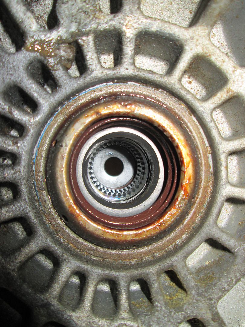
It didn't come out without a fight, but it is now out. You can see all the way through the hole in the center:


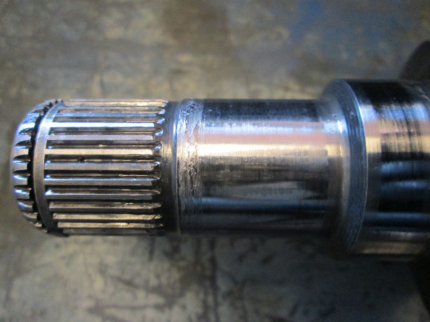
I suspect this is what was causing the axle to want to stay put. Not real sure what caused it, but I will just use another axle when it goes back together:


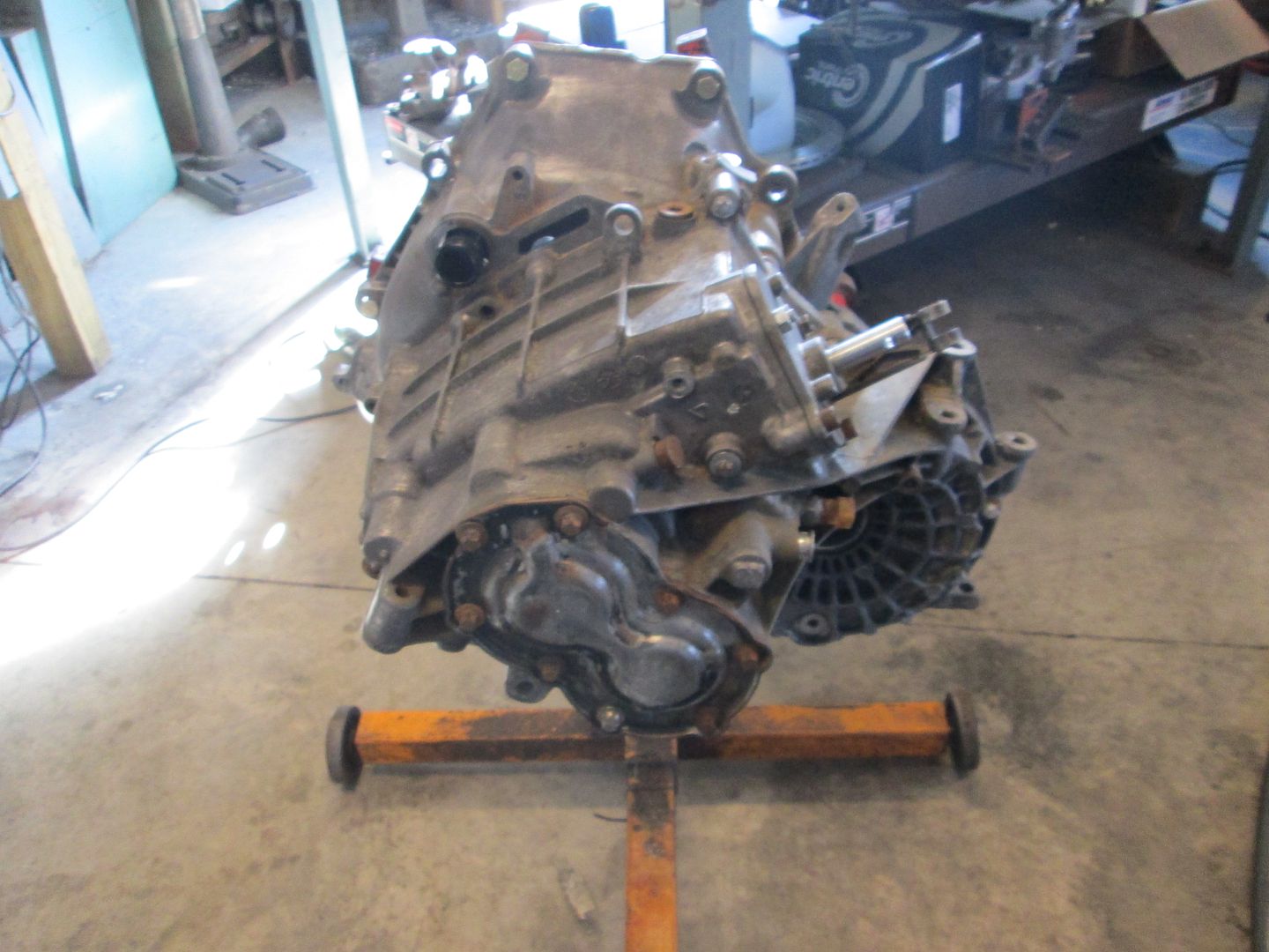
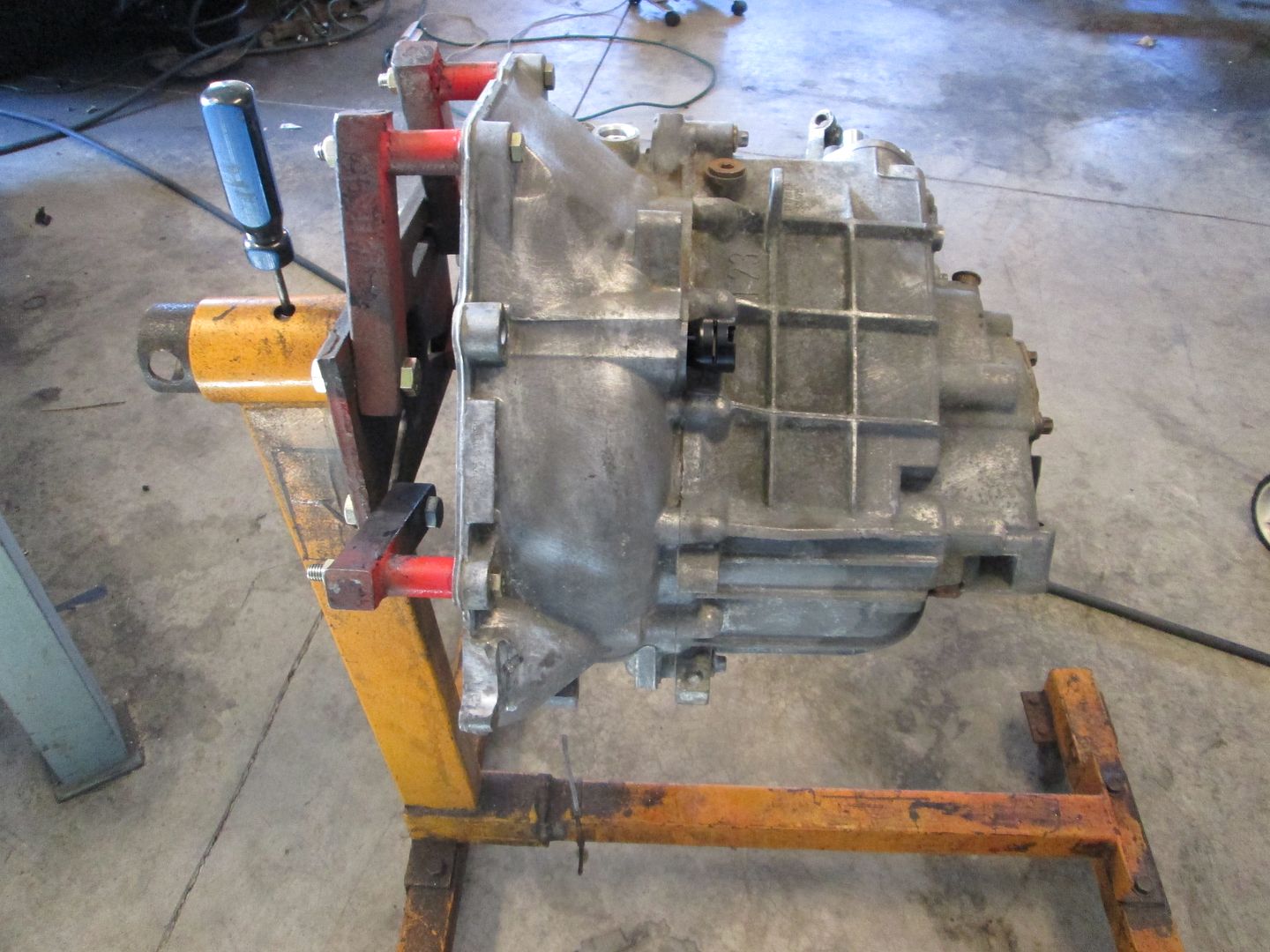
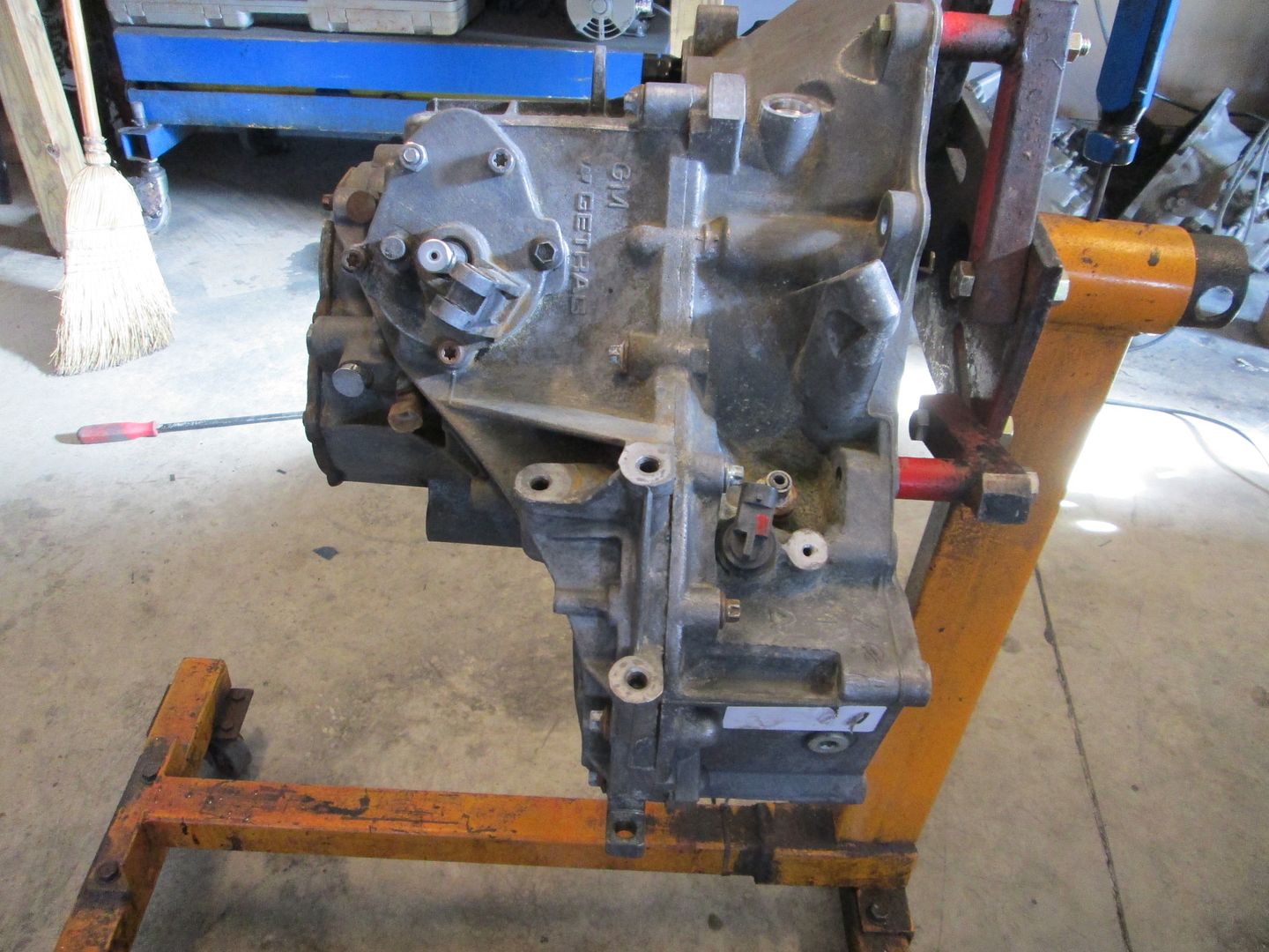
Been busy cleaning/scrubbing the transmission in preparation for painting...
IP: Logged
fieroguru
Member
Posts: 12128
From: Champaign, IL
Registered: Aug 2003


Feedback score:    (45)
Leave feedback


Total ratings: 258
Rate this member

Report this Post11-29-2013 05:39 PM Click Here to See the Profile for fieroguruSend a Private Message to fieroguruEdit/Delete MessageReply w/QuoteDirect Link to This Post

fieroguru

12128 posts
Member since Aug 2003
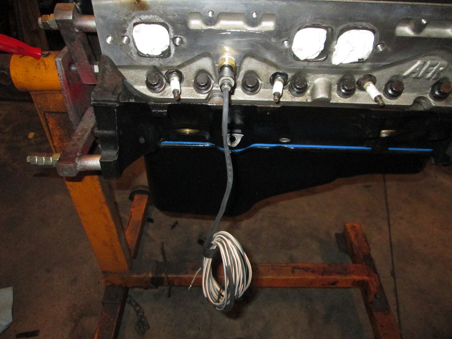
It was odd that there wasn't a cross shaft for the spider gears in the diff, so I pulled the VSS sensor and took a look inside. It has a limited slip (and a good one at that)!


After the transmission was cleaned, I put it on the engine stand a wire brushed it some more to remove as much oxidation from it prior to painting it:


Taped off or capped off everything that should be painted and then painted it:
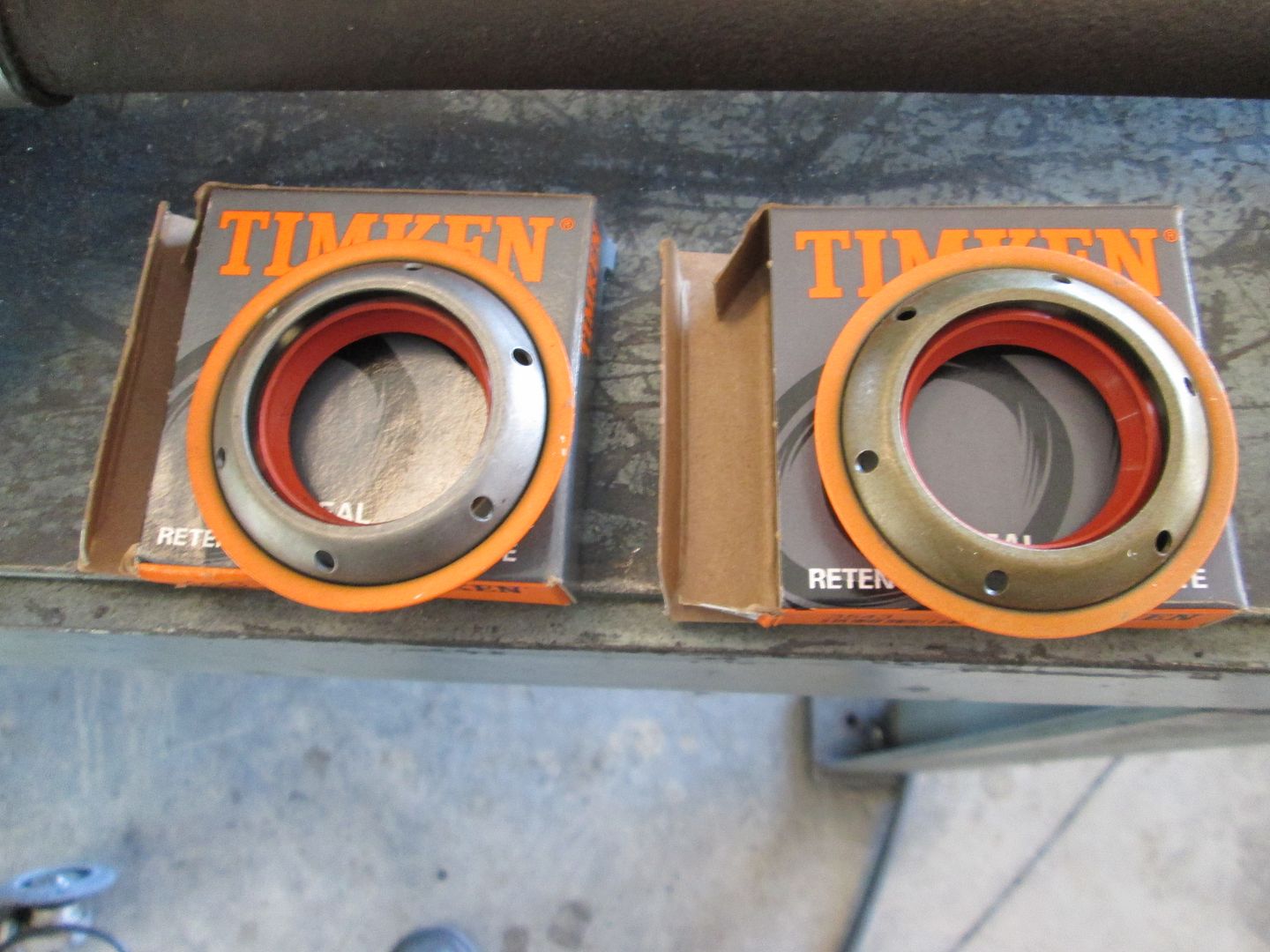

New Axle seals:


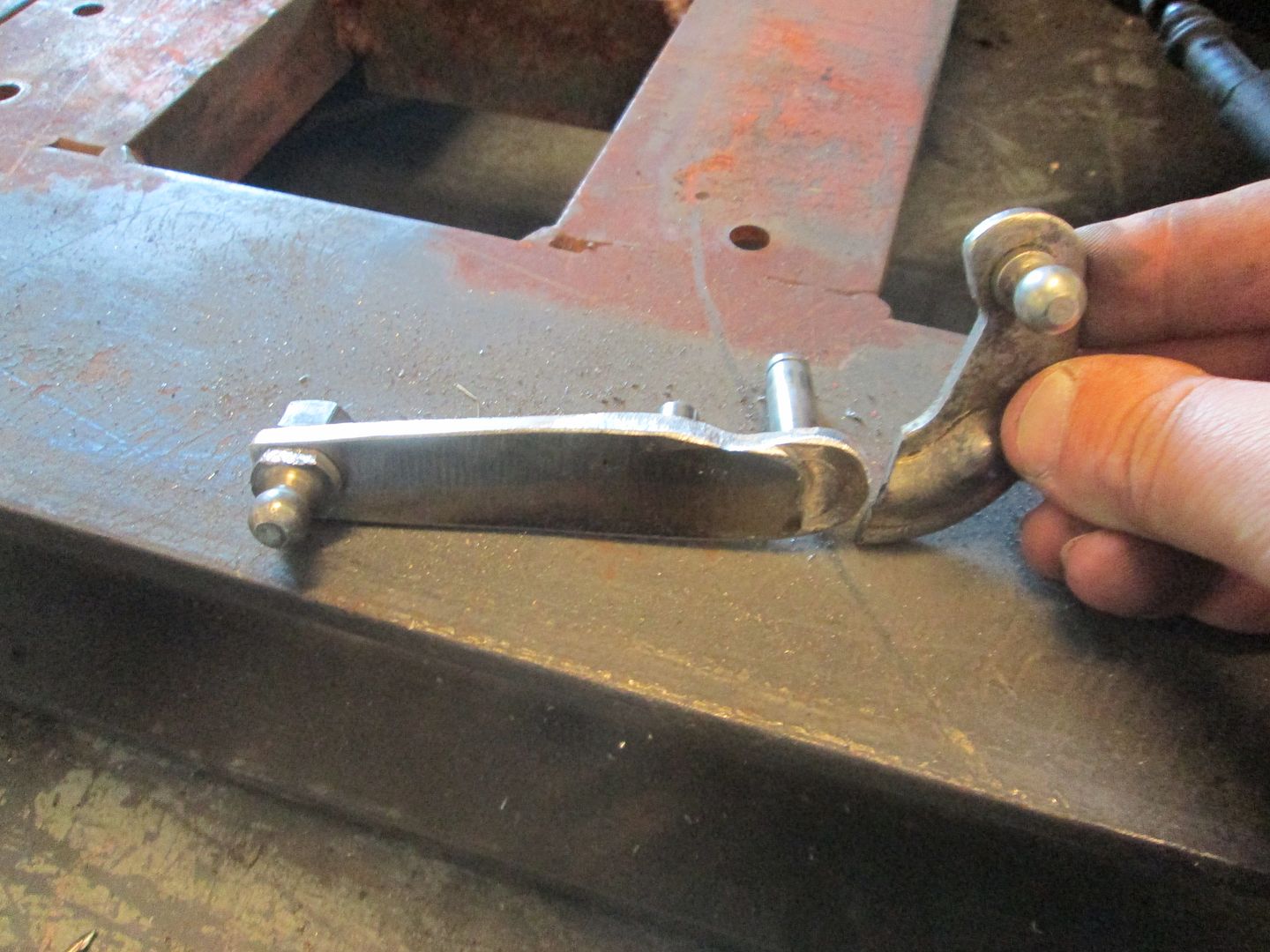
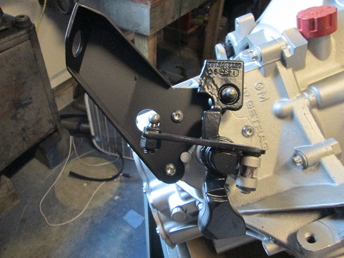
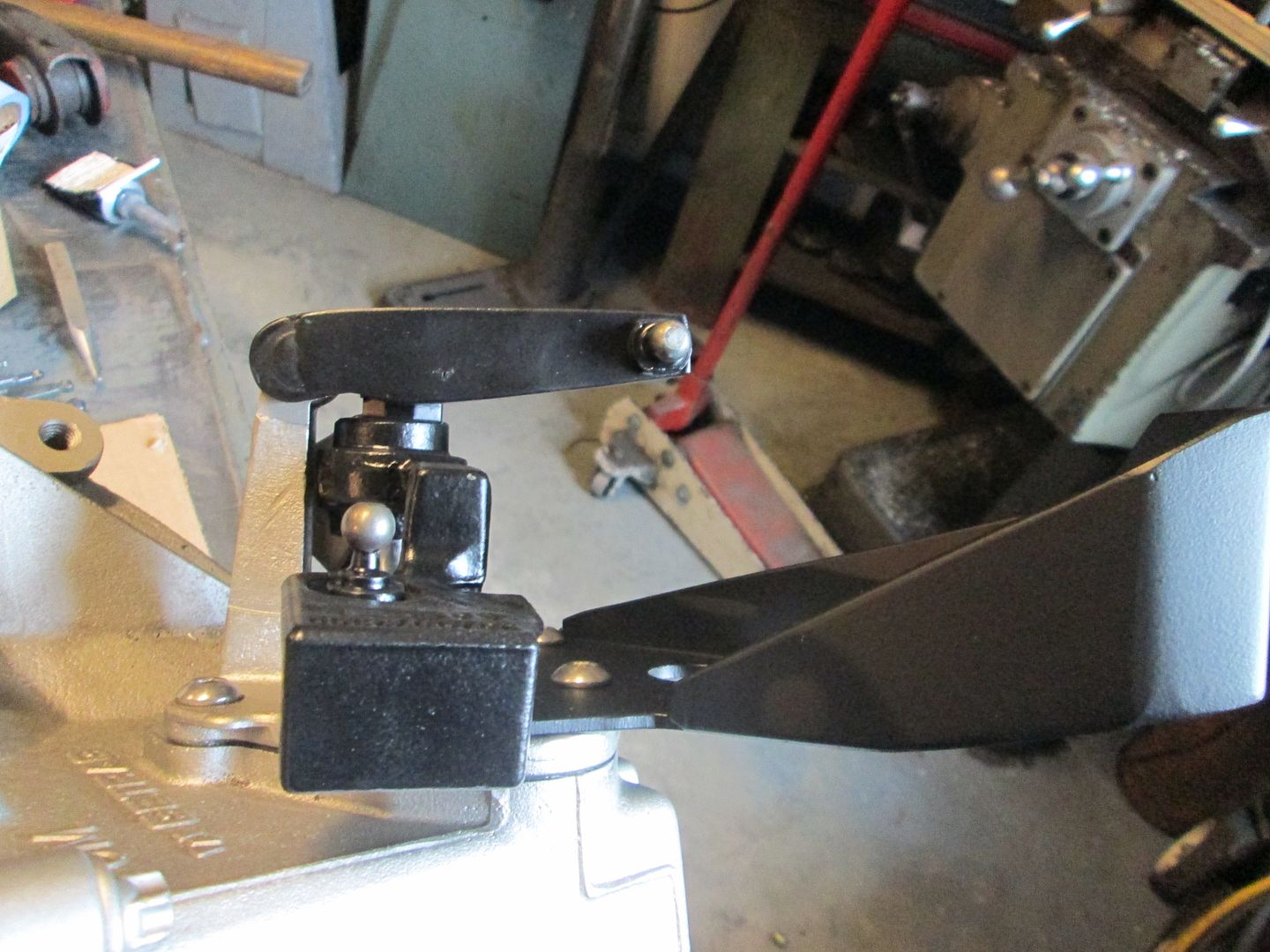
Then I reworked the shifter arm. I added some weld to build up some areas, ground everything smooth and removed the other side that wasn't needed any longer:


Cleaned and primed the shifter levers as well as the VSS bracket. I used tape to cover the ball studs, shafts and the square section that has a bushing slide in:

IP: Logged
fieroguru
Member
Posts: 12128
From: Champaign, IL
Registered: Aug 2003


Feedback score:    (45)
Leave feedback


Total ratings: 258
Rate this member

Report this Post11-30-2013 05:41 PM Click Here to See the Profile for fieroguruSend a Private Message to fieroguruEdit/Delete MessageReply w/QuoteDirect Link to This Post
Sanded the coolant crossover tube and primed it:


Same with the cold air intake:


Still working on wire wheeling the cradle:


IP: Logged
fieroguru
Member
Posts: 12128
From: Champaign, IL
Registered: Aug 2003


Feedback score:    (45)
Leave feedback


Total ratings: 258
Rate this member

Report this Post12-01-2013 06:57 PM Click Here to See the Profile for fieroguruSend a Private Message to fieroguruEdit/Delete MessageReply w/QuoteDirect Link to This Post
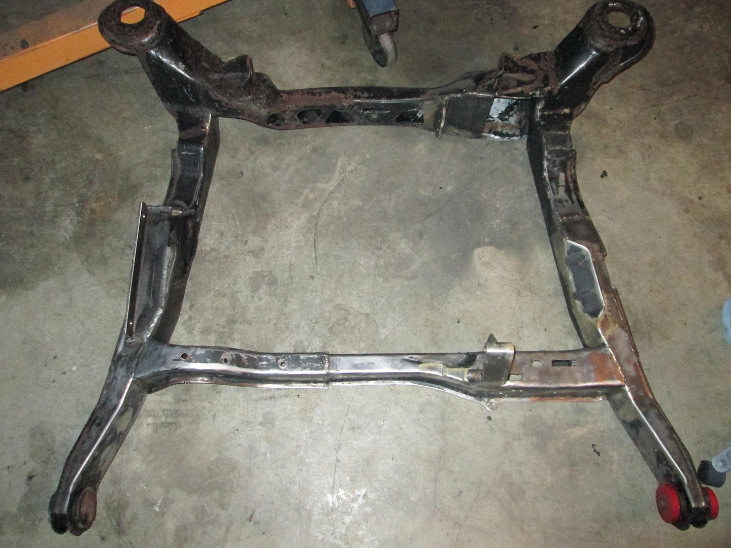
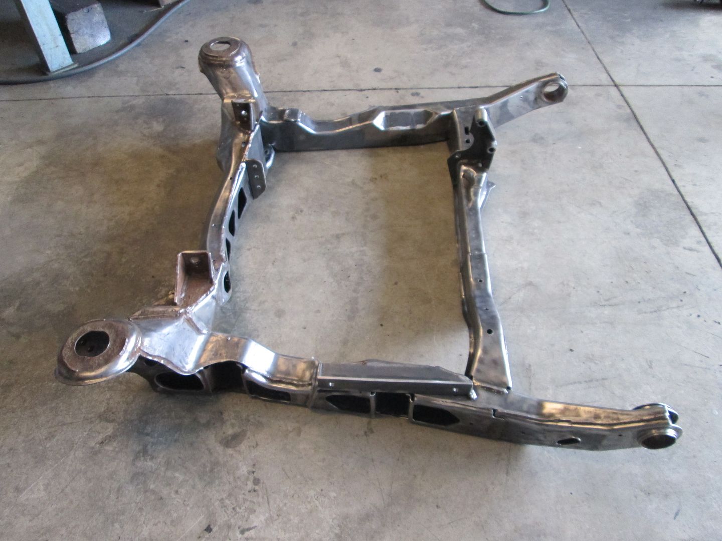
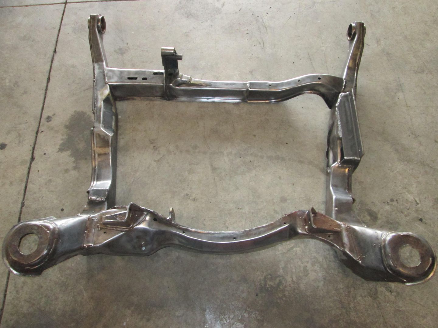
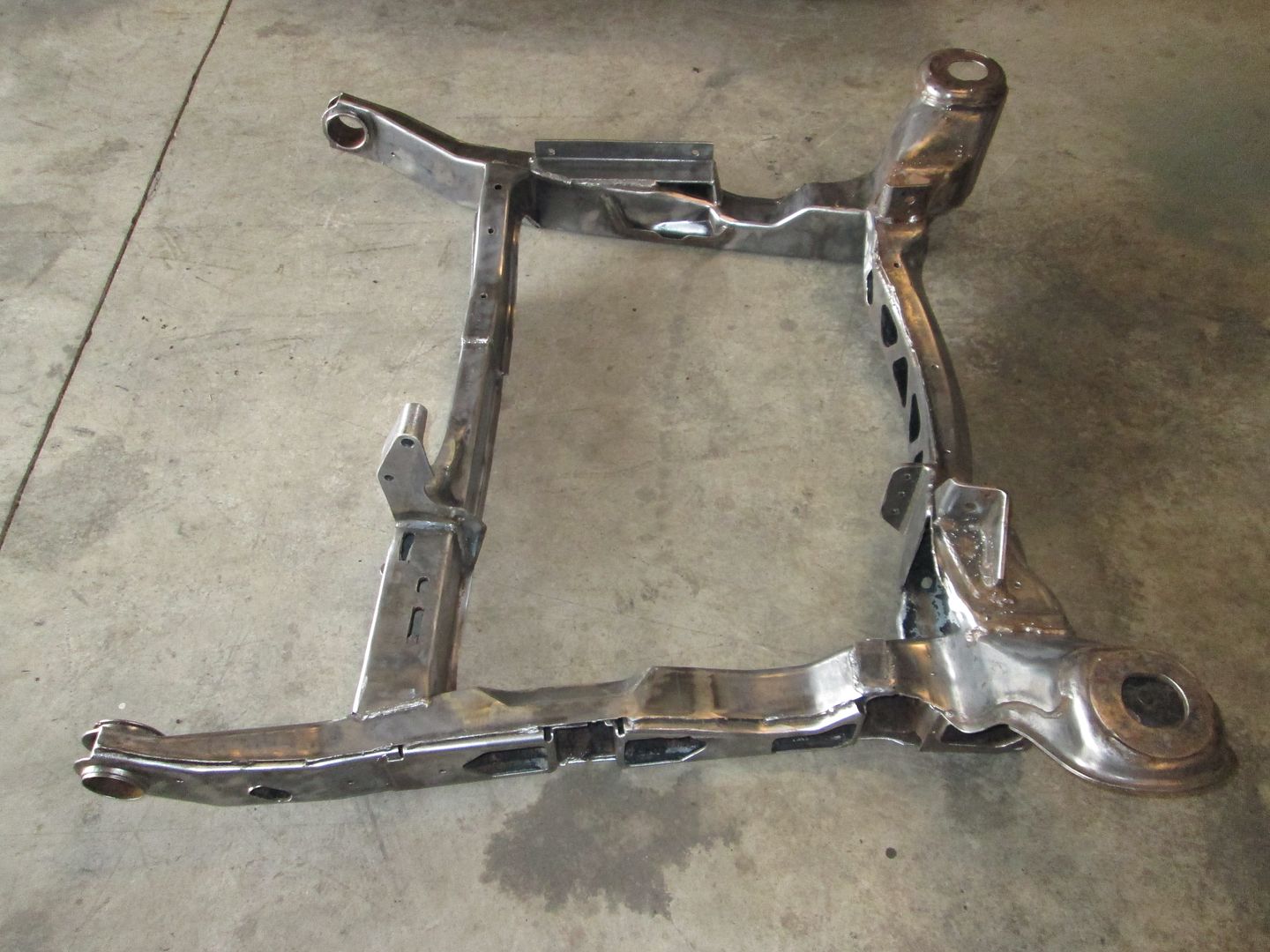
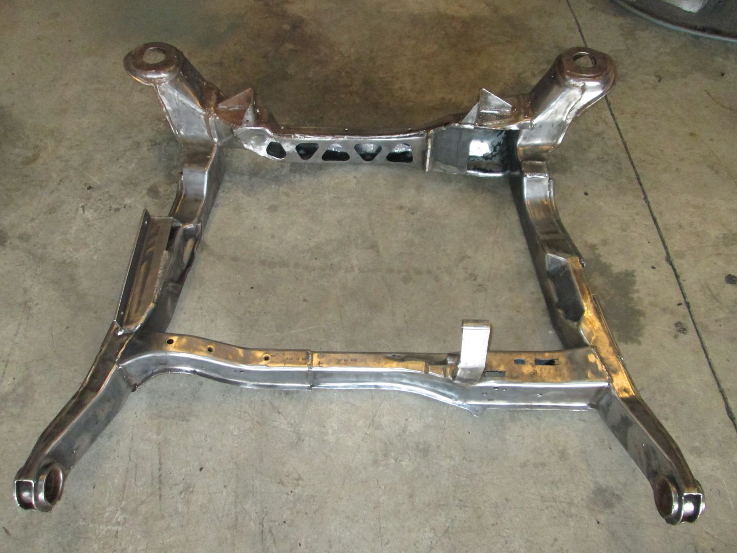
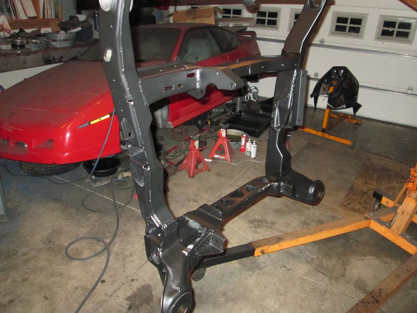
The cradle had a layer or two of paint, then topped with POR15 (which doesn't stick to paint or clean metal for that matter), so it was a pealing mess. I ended up wire brushing the whole thing down to bare metal:


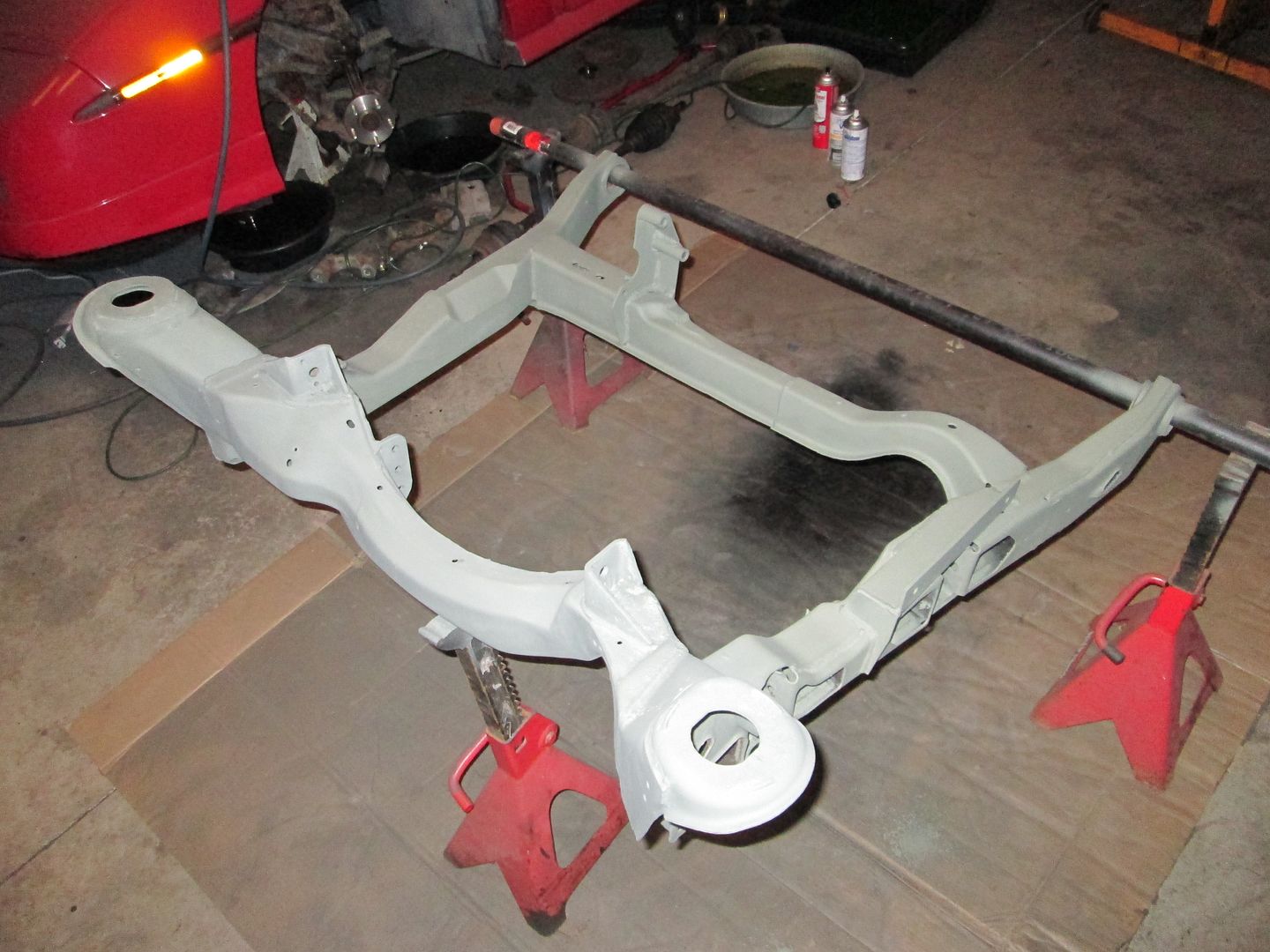
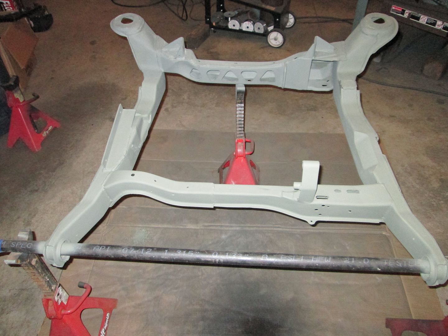
Then primed it with self etching primer like all the other parts:


I think on Tuesday I will mix up some black paint and have a little parts painting party...
IP: Logged
Jims88
Member
Posts: 268
From: Kalamazoo MI
Registered: Jul 2011


Feedback score: (1)
Leave feedback

Rate this member

Report this Post12-02-2013 06:55 PM Click Here to See the Profile for Jims88Send a Private Message to Jims88Edit/Delete MessageReply w/QuoteDirect Link to This Post
WOW that's some serious wire brushing!
Turned out nice though!
IP: Logged
fieroguru
Member
Posts: 12128
From: Champaign, IL
Registered: Aug 2003


Feedback score:    (45)
Leave feedback


Total ratings: 258
Rate this member

Report this Post12-02-2013 07:32 PM Click Here to See the Profile for fieroguruSend a Private Message to fieroguruEdit/Delete MessageReply w/QuoteDirect Link to This Post
 
quote
Originally posted by Jims88:

WOW that's some serious wire brushing!
Turned out nice though!


This thing did most of the work, but for some reason my right arm was still numb after using it for several hours.
IP: Logged
PFF
System Bot
ericjon262
Member
Posts: 3082
From: everywhere.
Registered: Jan 2010


Feedback score:    (10)
Leave feedback


Total ratings: 66
Rate this member

Report this Post12-02-2013 08:46 PM Click Here to See the Profile for ericjon262Send a Private Message to ericjon262Edit/Delete MessageReply w/QuoteDirect Link to This Post
how many wires have you pulled out of your forearms today?

------------------
we're in desperate need of a little more religion to nurse your god-like point of view...

Built not bought... Because bolt-ons don't.

https://www.fiero.nl/forum/Forum2/HTML/119122.html

IP: Logged
fieroguru
Member
Posts: 12128
From: Champaign, IL
Registered: Aug 2003


Feedback score:    (45)
Leave feedback


Total ratings: 258
Rate this member

Report this Post12-02-2013 09:01 PM Click Here to See the Profile for fieroguruSend a Private Message to fieroguruEdit/Delete MessageReply w/QuoteDirect Link to This Post
 
quote
Originally posted by ericjon262:
how many wires have you pulled out of your forearms today?


None. I wore leather gloves and heavy coat, but each time I took a break to rest my arm, I did pull a bunch of wires from everything I was wearing.
IP: Logged
zkhennings
Member
Posts: 1922
From: Massachusetts, USA
Registered: Oct 2010


Feedback score: (3)
Leave feedback

Rate this member

Report this Post12-03-2013 07:42 PM Click Here to See the Profile for zkhenningsSend a Private Message to zkhenningsEdit/Delete MessageReply w/QuoteDirect Link to This Post
 
quote
Originally posted by fieroguru:


None. I wore leather gloves and heavy coat, but each time I took a break to rest my arm, I did pull a bunch of wires from everything I was wearing.


The worst is pulling wires out of your stomach!
IP: Logged
fieroguru
Member
Posts: 12128
From: Champaign, IL
Registered: Aug 2003


Feedback score:    (45)
Leave feedback


Total ratings: 258
Rate this member

Report this Post12-03-2013 08:54 PM Click Here to See the Profile for fieroguruSend a Private Message to fieroguruEdit/Delete MessageReply w/QuoteDirect Link to This Post
The headers are done at the coaters and should be here later this week.

I was able to get all the primed parts painted this evening, but will take the pictures on Wednesday.
IP: Logged
fieroguru
Member
Posts: 12128
From: Champaign, IL
Registered: Aug 2003


Feedback score:    (45)
Leave feedback


Total ratings: 258
Rate this member

Report this Post12-04-2013 08:15 PM Click Here to See the Profile for fieroguruSend a Private Message to fieroguruEdit/Delete MessageReply w/QuoteDirect Link to This Post
Here are some painted pics:


IP: Logged
fieroguru
Member
Posts: 12128
From: Champaign, IL
Registered: Aug 2003


Feedback score:    (45)
Leave feedback


Total ratings: 258
Rate this member

Report this Post12-05-2013 09:36 PM Click Here to See the Profile for fieroguruSend a Private Message to fieroguruEdit/Delete MessageReply w/QuoteDirect Link to This Post
The headers came back today from the coaters:


IP: Logged
fieroguru
Member
Posts: 12128
From: Champaign, IL
Registered: Aug 2003


Feedback score:    (45)
Leave feedback


Total ratings: 258
Rate this member

Report this Post12-07-2013 02:34 PM Click Here to See the Profile for fieroguruSend a Private Message to fieroguruEdit/Delete MessageReply w/QuoteDirect Link to This Post
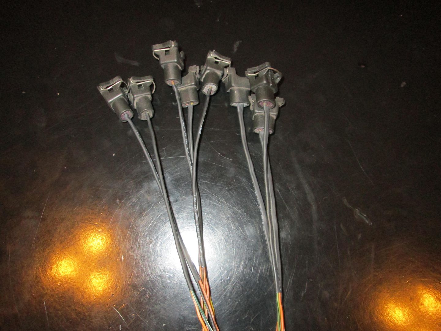
As I work to start putting everything back together, I needed to build the injector harness because it ends up sandwiched between the plenum and lower intake. So I started with the injector pigtails and put about 6" of shrink tube on them to protect the wires:


Then I started with a stock LS van harness (PCM mounted inside) that looked like this:


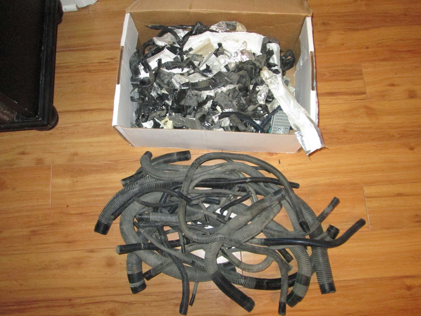
Removed all this stuff:


None of this is needed either (auto trans, post cat O2s, evap, abs, fuel tank stuff, oil pressure stuff, and other wires that I will use the fiero 203/500 harness for):


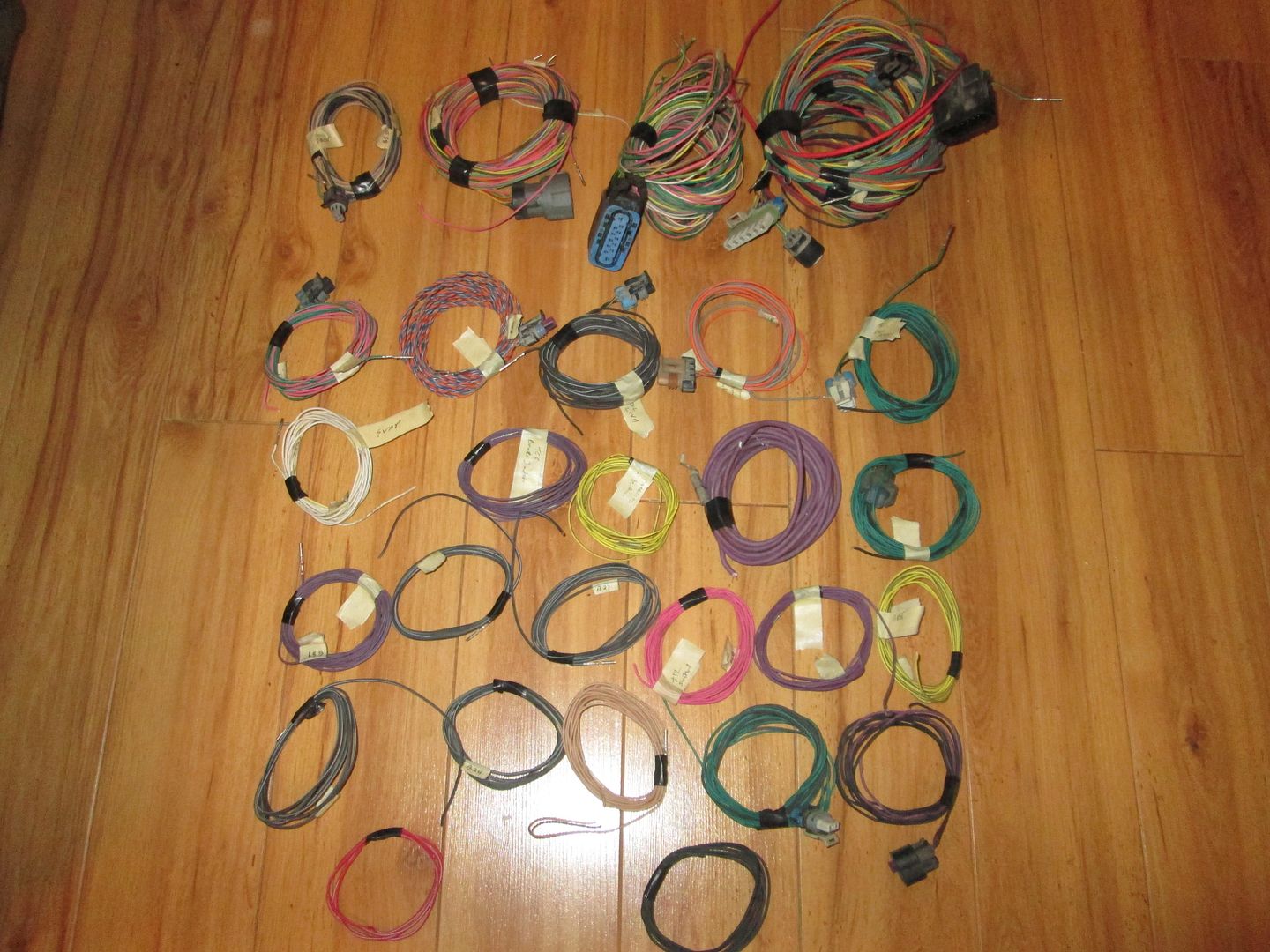
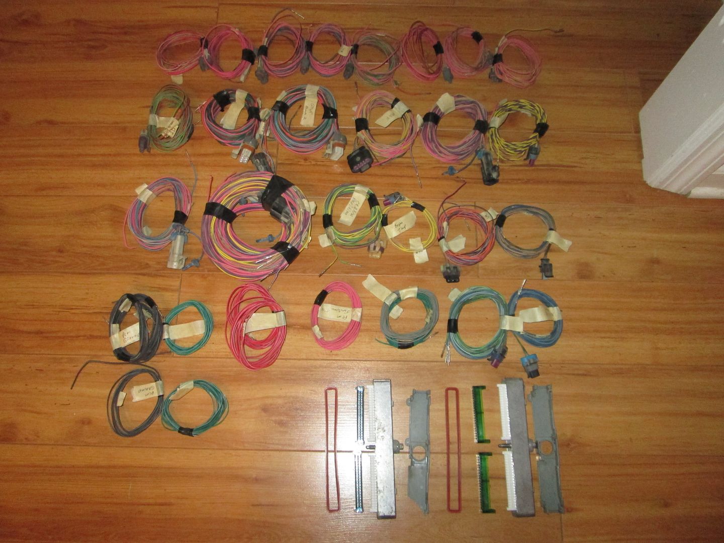
Here is what I need of the old stock harness to make the new one:


Now I will get started on the injector harness...

IP: Logged
fieroguru
Member
Posts: 12128
From: Champaign, IL
Registered: Aug 2003


Feedback score:    (45)
Leave feedback


Total ratings: 258
Rate this member

Report this Post12-07-2013 07:48 PM Click Here to See the Profile for fieroguruSend a Private Message to fieroguruEdit/Delete MessageReply w/QuoteDirect Link to This Post

fieroguru

12128 posts
Member since Aug 2003
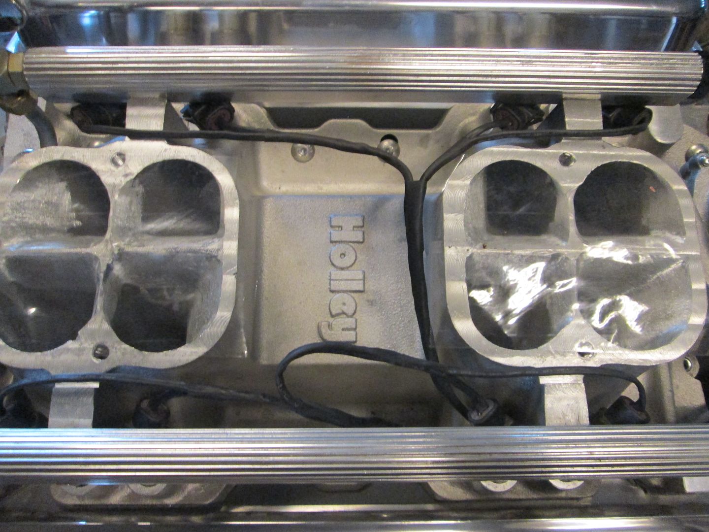
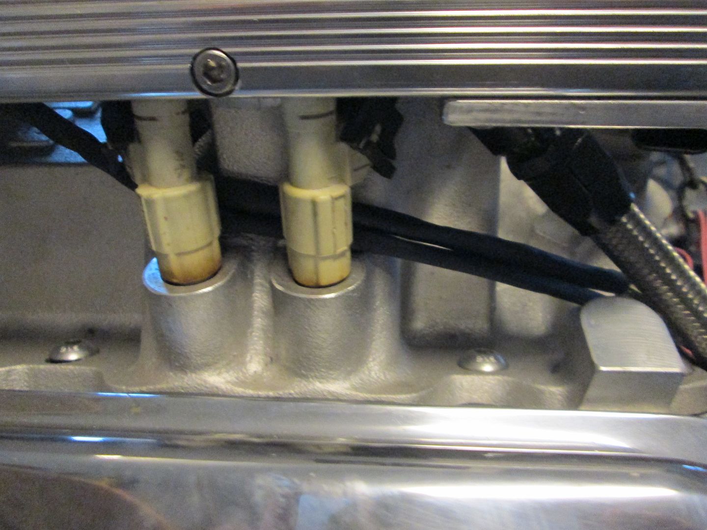
Started building the harness at the injectors. All the injectors are spun around so the connector is hidden behind the fuel rail.


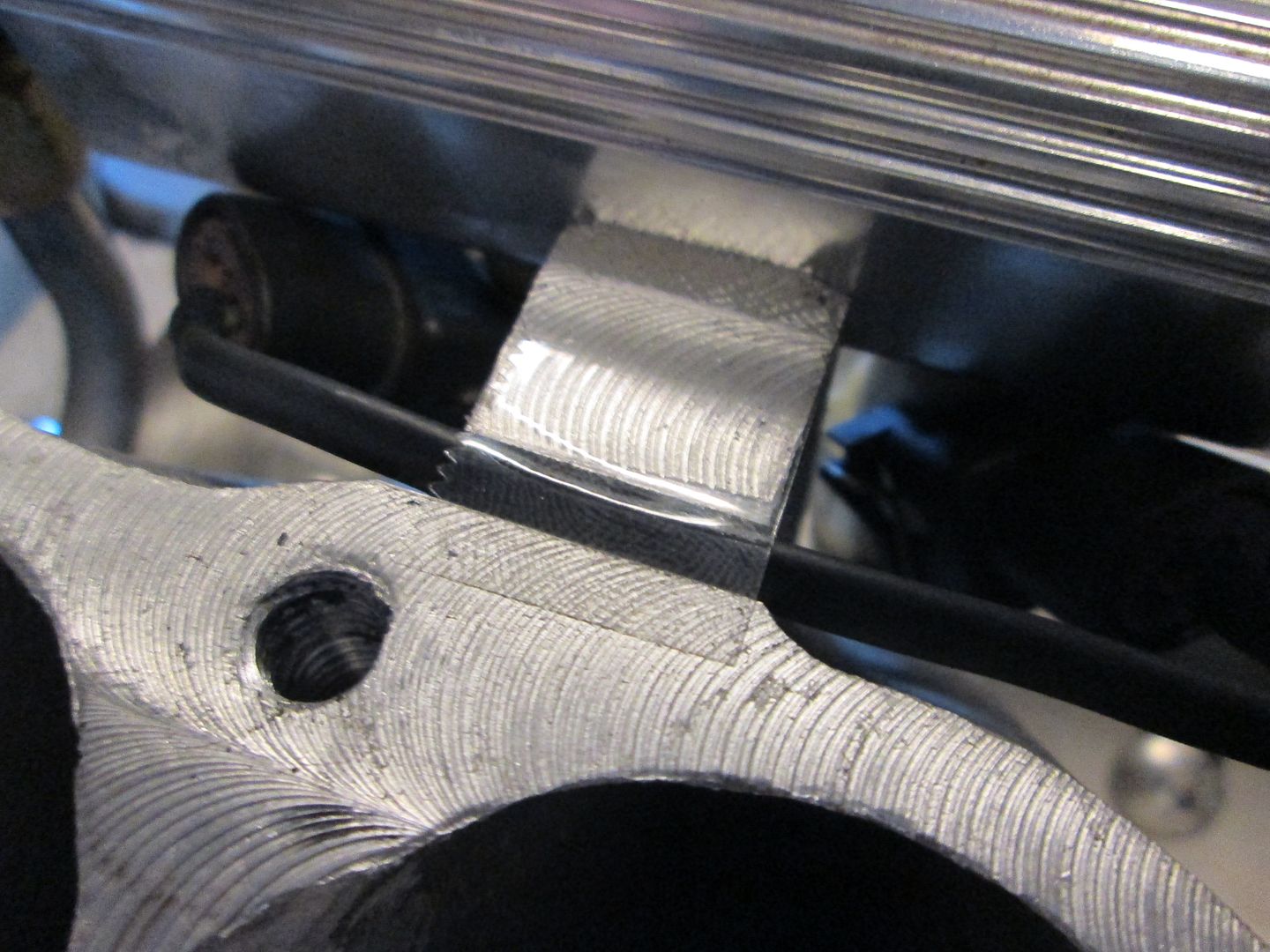
Taped down the harness into the grooves so the plenum won't pinch them.


Each bank was kept separate mainly so they could pass between the injectors and lower intake to keep them as hidden as possible. I will loom them together after the injectors:


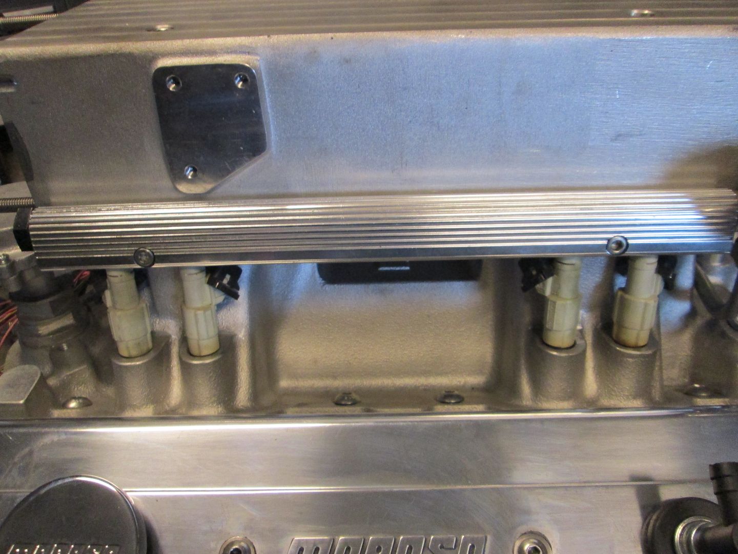
View from the front side with the injector harness complete... no visible wires!:


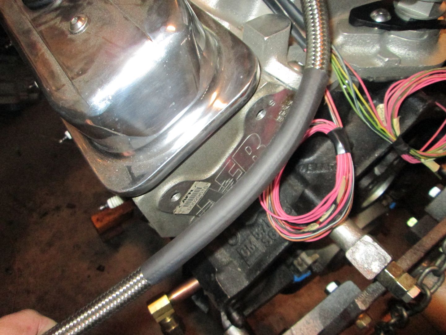
Installed the brake booster line and added some heat shrink to it so it doesn't wear the paint off the coil bracket:


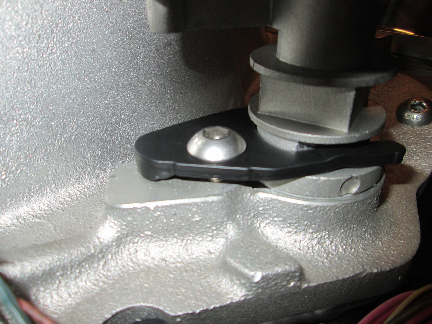
Installed the distributor hold down:


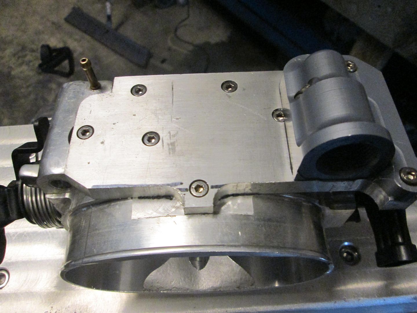
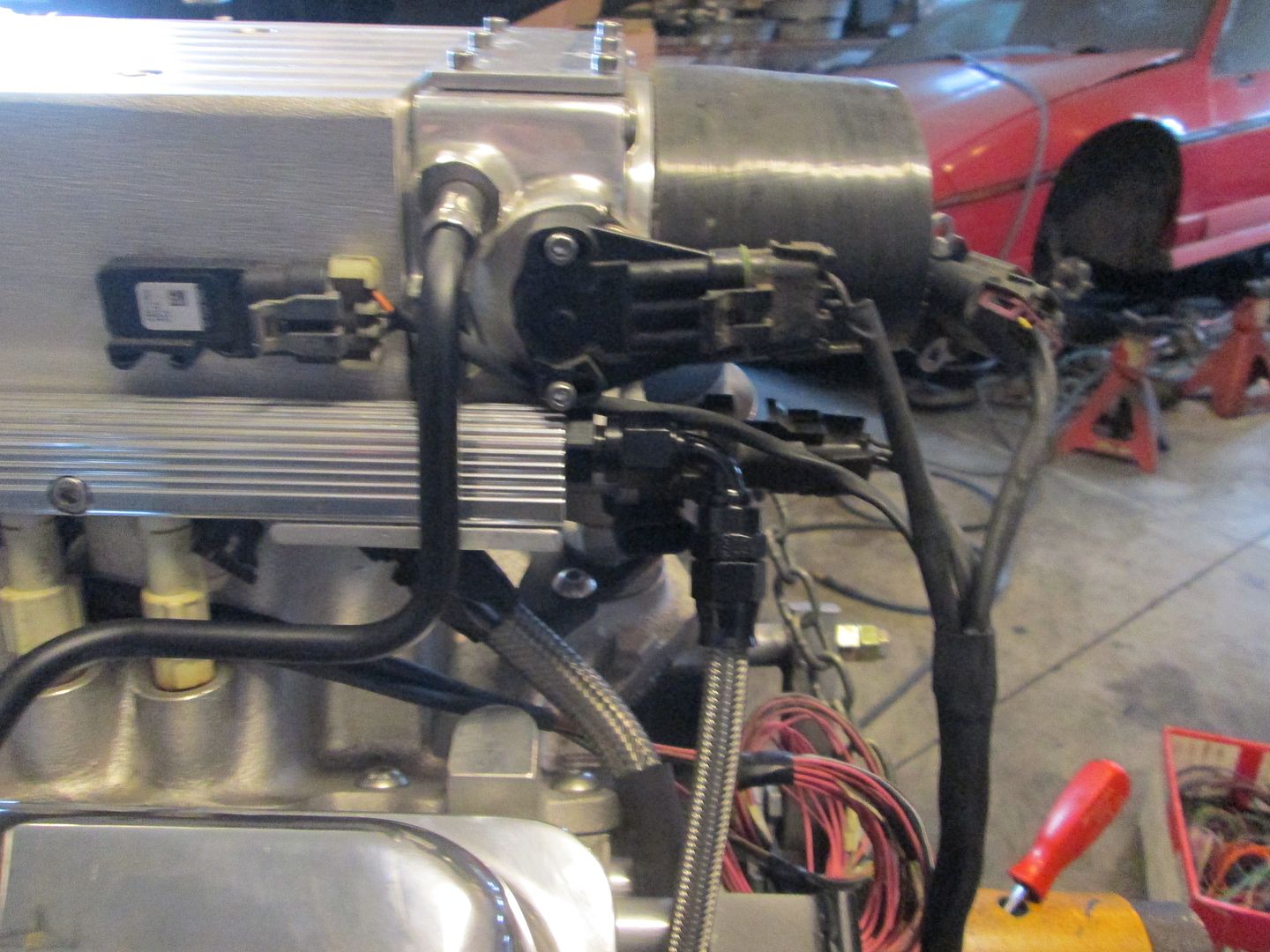
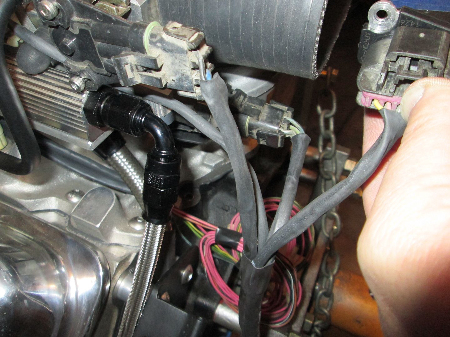
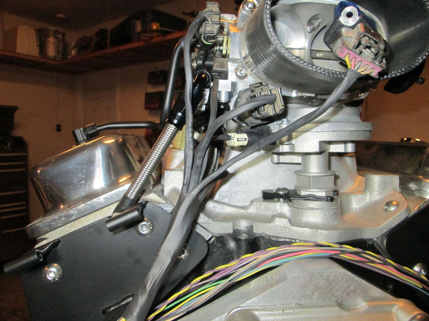
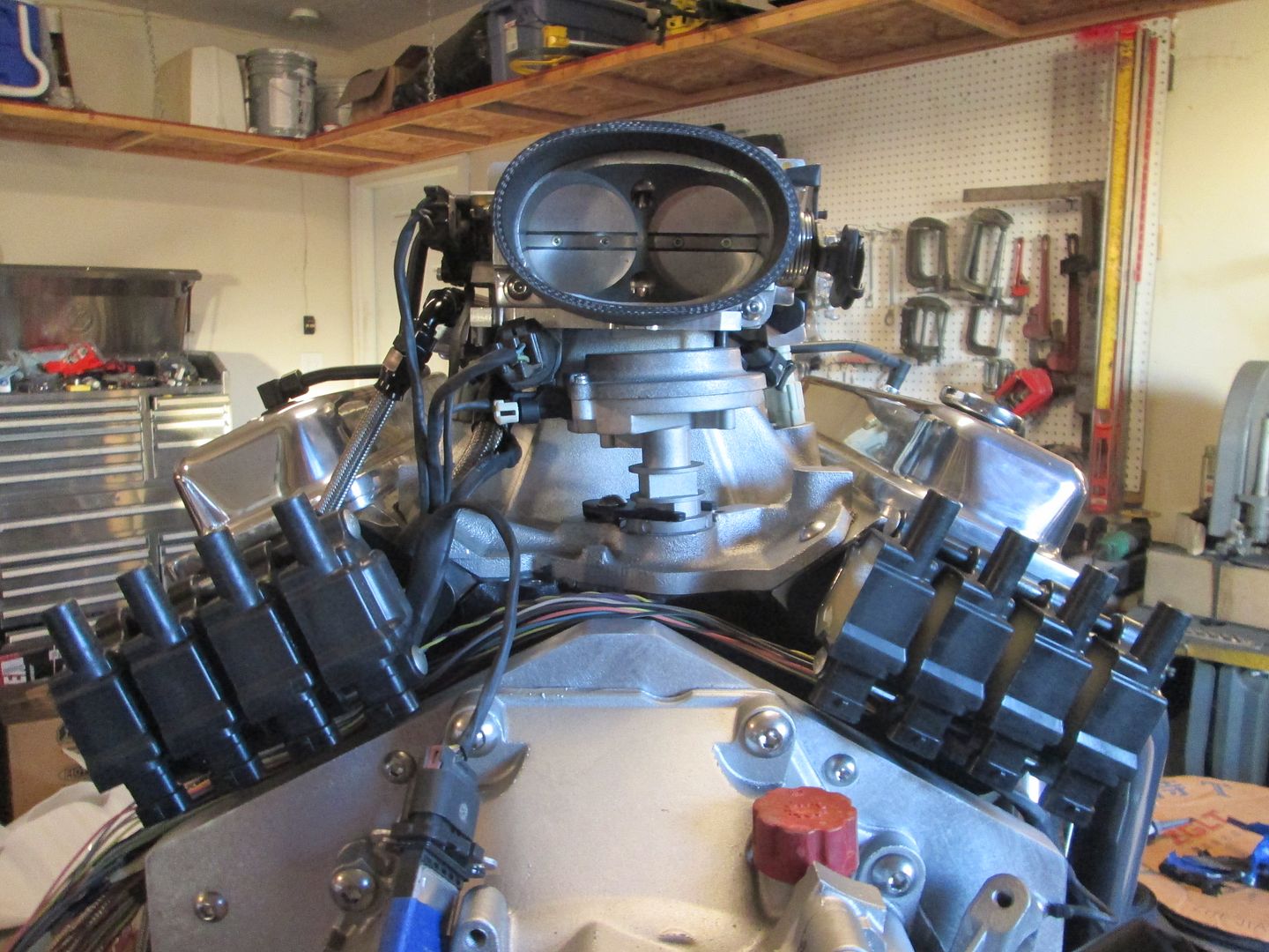
Sealed the base plate on the throttle body and installed the IAC housing:


Installed the cable pull on the throttle body, the throttle body itself, the throttle cable bracket and the rear PCV line:
IP: Logged
fieroguru
Member
Posts: 12128
From: Champaign, IL
Registered: Aug 2003


Feedback score:    (45)
Leave feedback


Total ratings: 258
Rate this member

Report this Post12-08-2013 03:15 PM Click Here to See the Profile for fieroguruSend a Private Message to fieroguruEdit/Delete MessageReply w/QuoteDirect Link to This Post
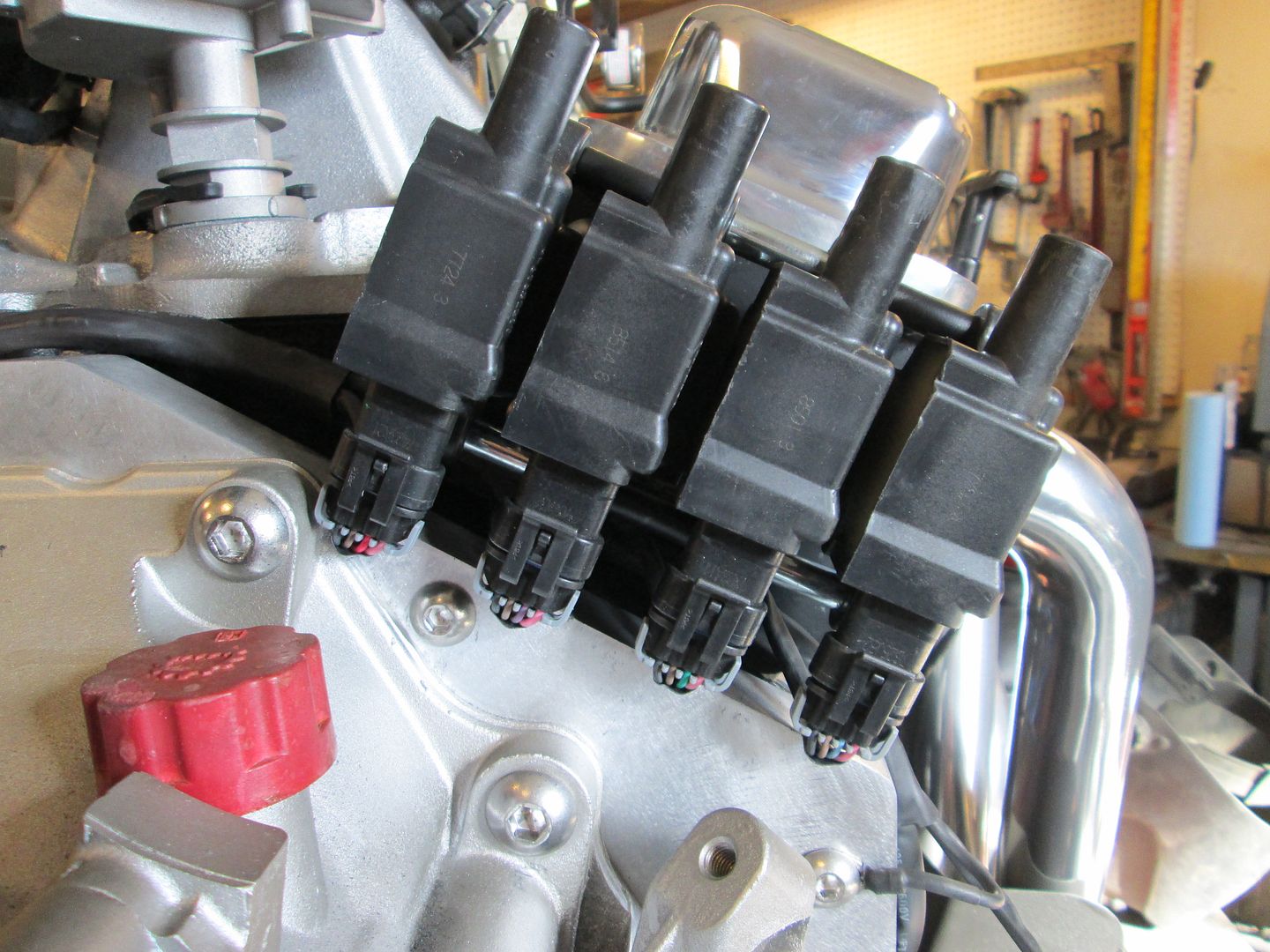
Did a little more harness work. This engine/intake/ecm combo means a mixture of sensors and connector ends.

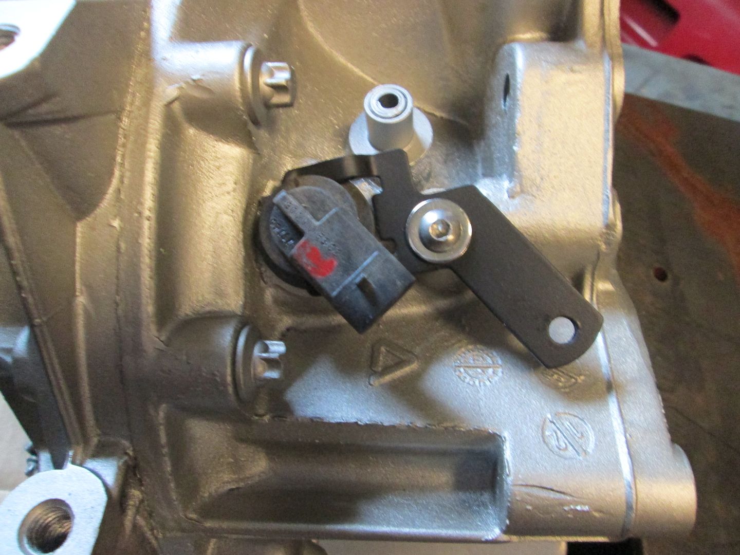
The Crank & Cam Sensors and pigtails come from the L31 (96-2002 Vortec 350).
The TPS and IAC Sensors and pigtails come from the 85-91 TPI applications (fiero V6 pigtails can be used as well).
The Knock Sensors come from a 95-96 LT1, pigtails come from any GM single wire knock sensor.
The 3 wire coolant switch allows only 1 coolant sensor, there was a left over pigtail post harness disassemble that will work for this (ECM oil pressure sender).
The MAP sensor and pigtail are LS1 (pigtail came with harness)
The MAF is LS7, but the 06 harness I am using had the right MAF connector.

Loomed up the TPS, IAC, MAF and ECT wires (I still need to clean some of the connectors):


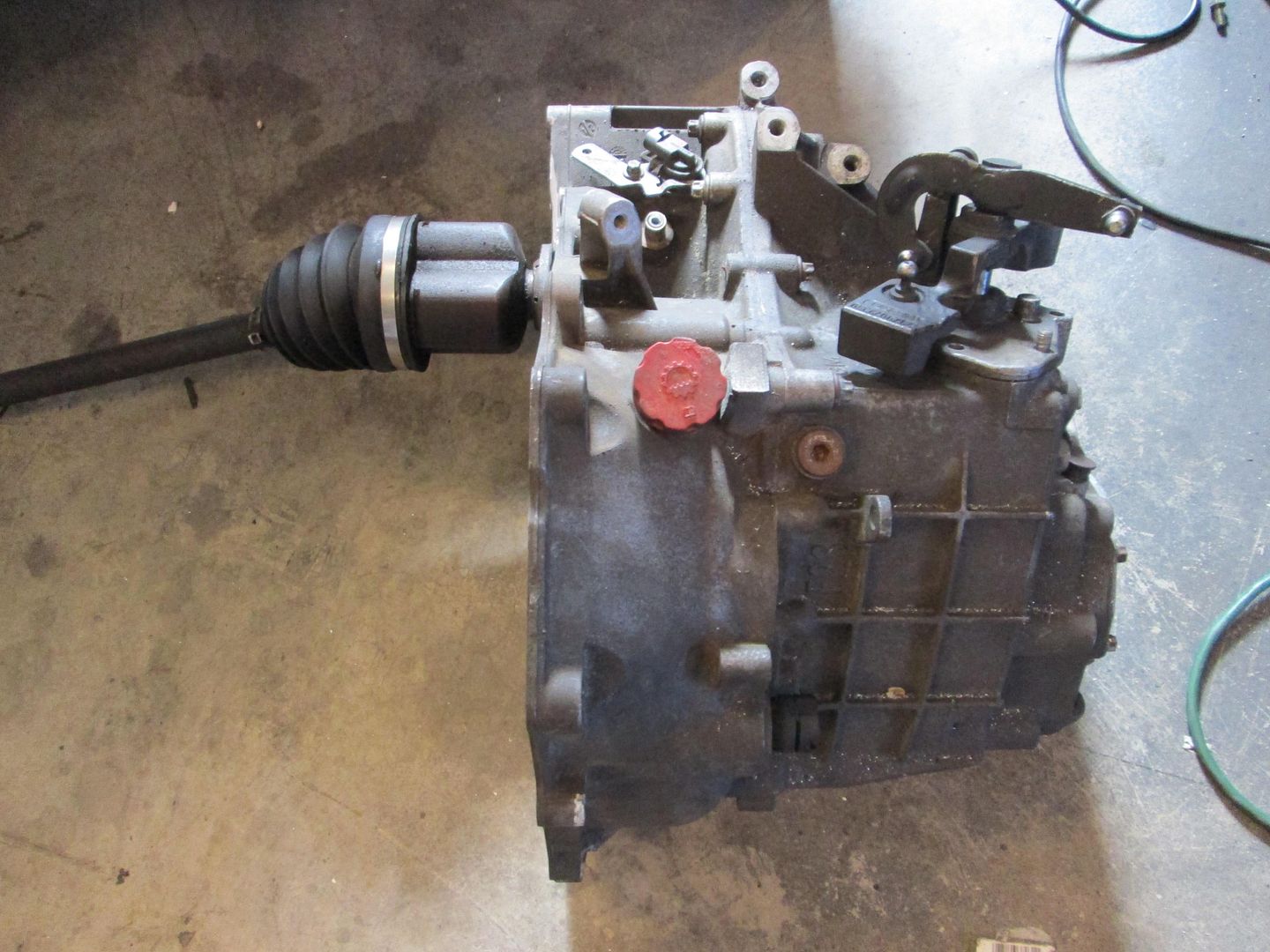
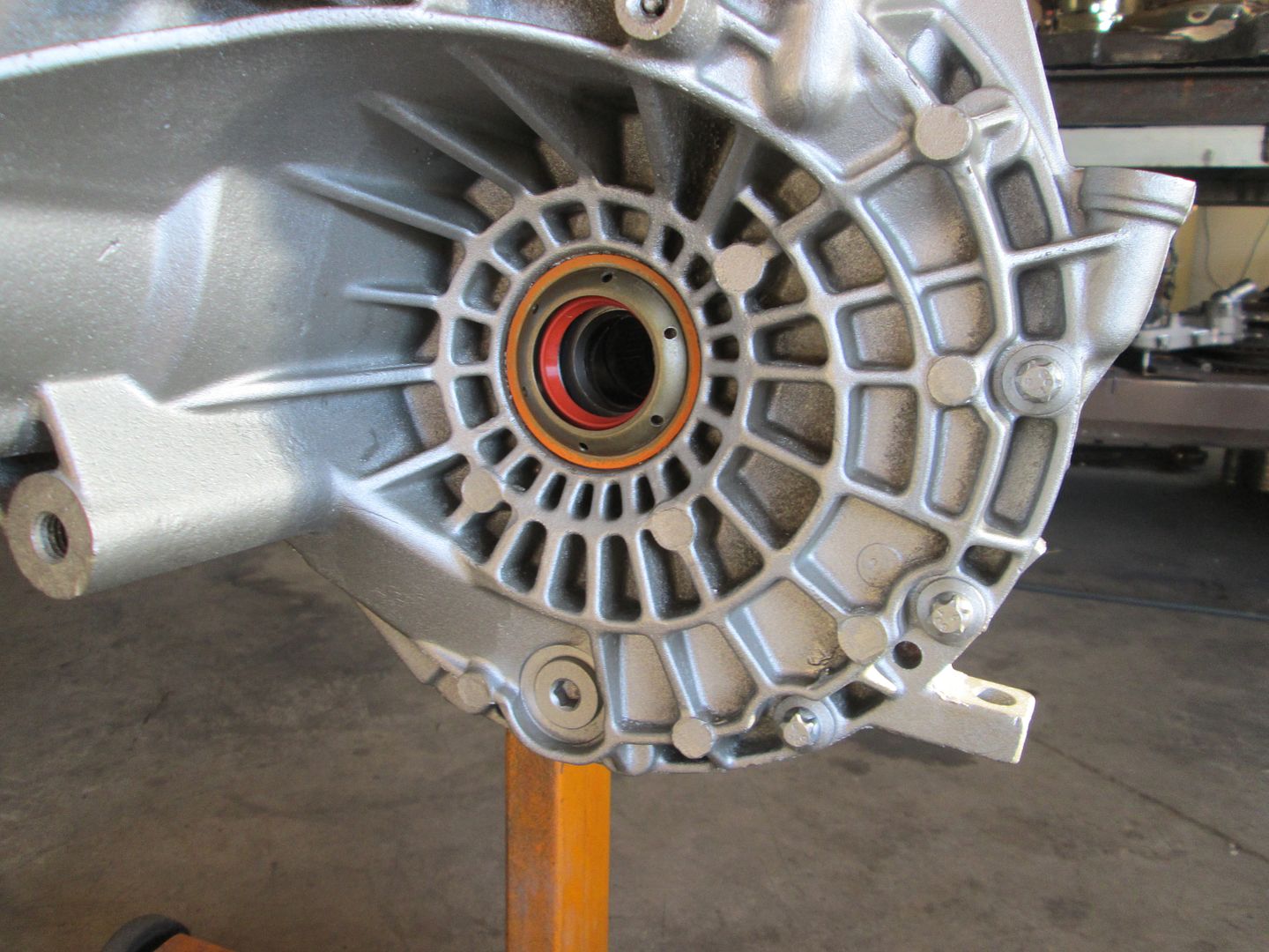
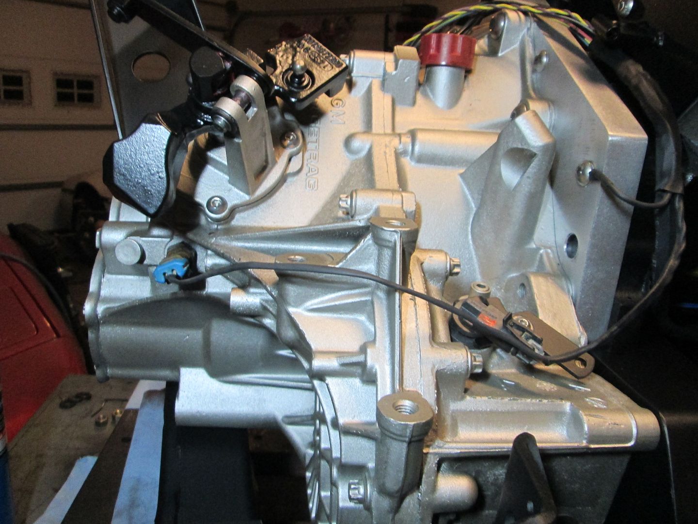
Then I put the VSS bracket back on the transmission:


Installed the shifter levers and cable bracket:


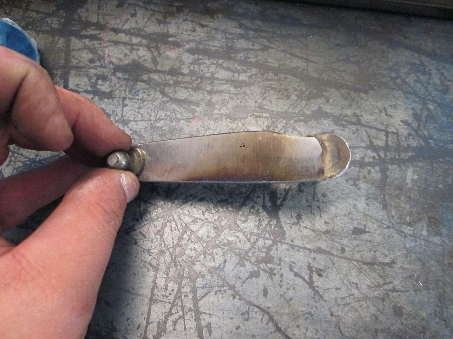
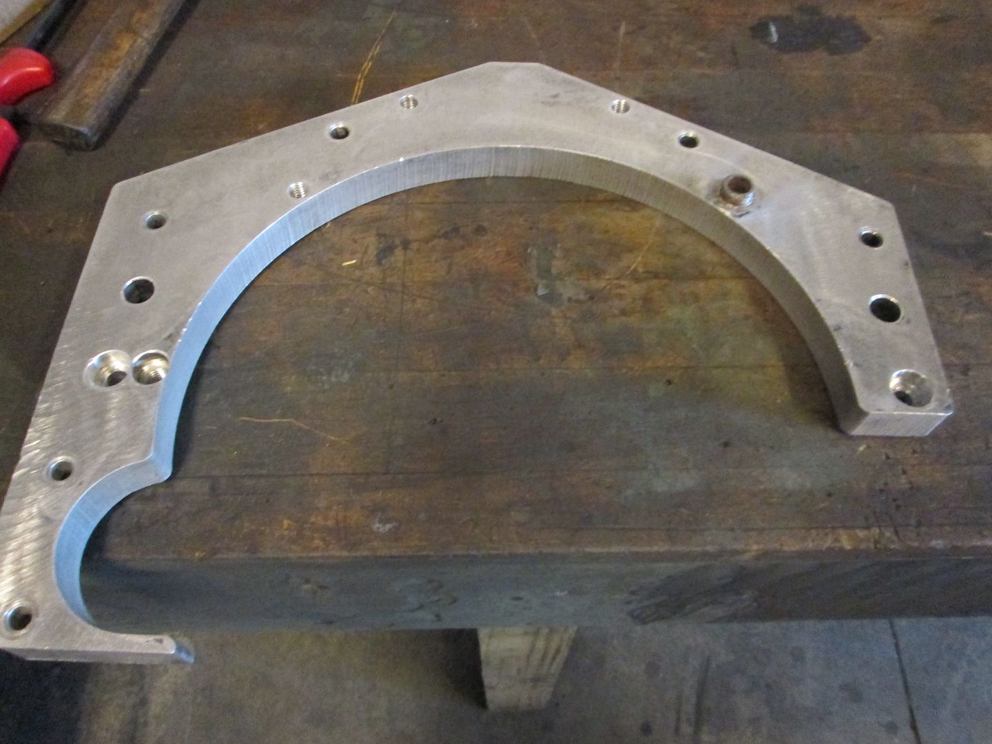
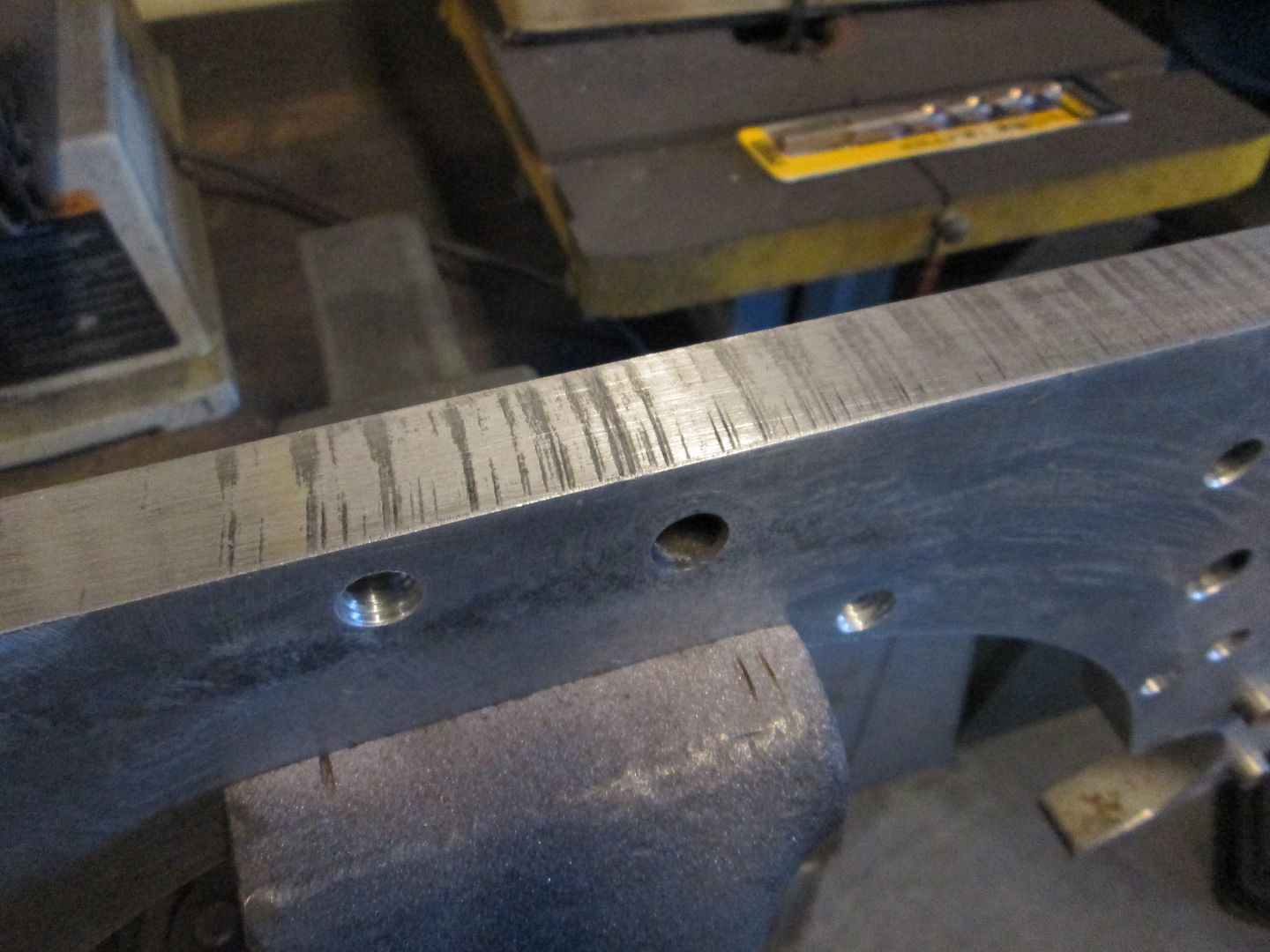
Cleaned all the paint off the adapter plate. I want to sand/smooth it so it looks good again.


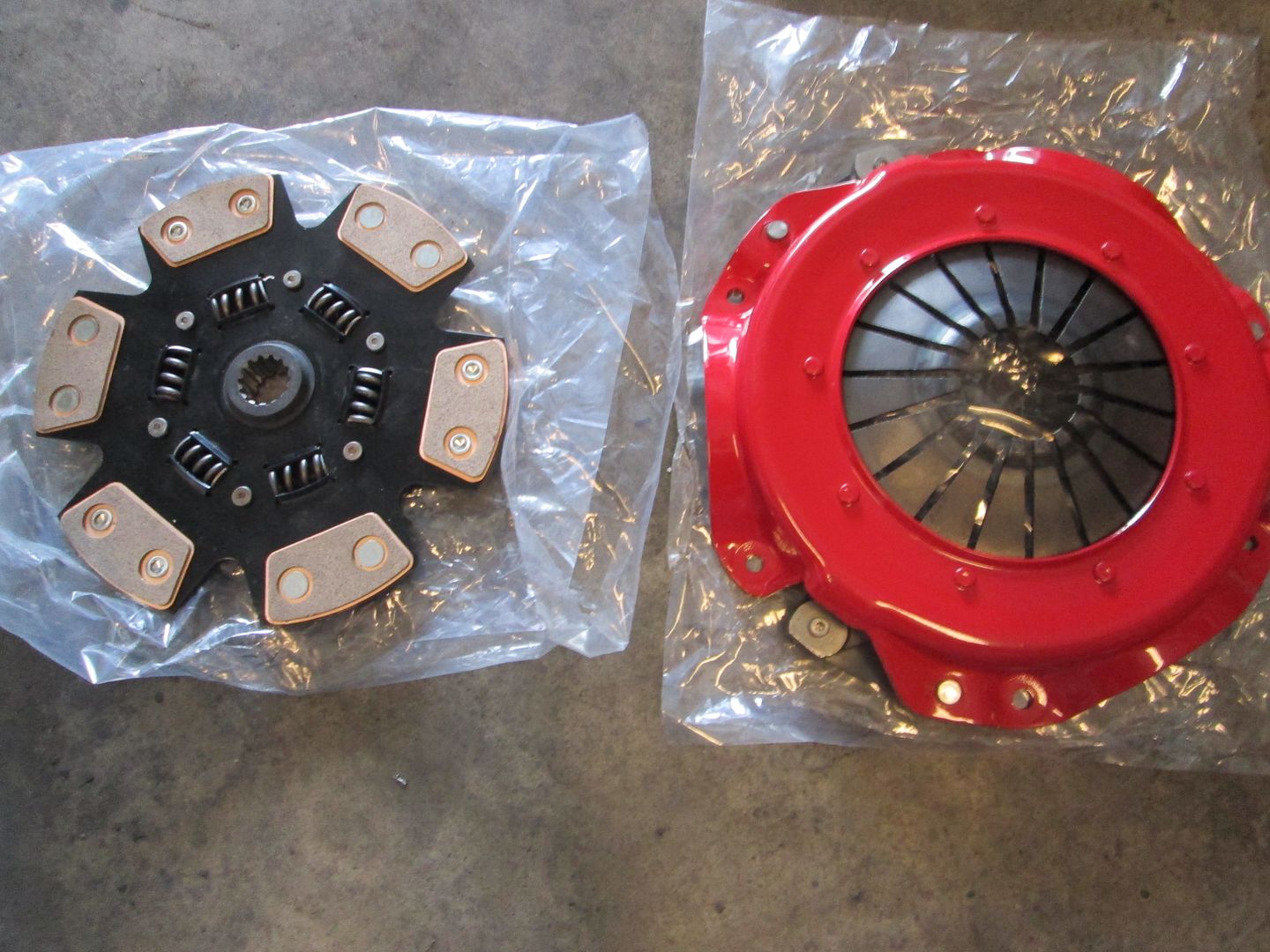
I am traveling for work this next week, so don't expect any significant updates until next weekend. The pressure plate should arrive while I am gone, so when I get back I can put the engine/transmission together and back on the cradle.

[This message has been edited by fieroguru (edited 12-08-2013).]

IP: Logged
motoracer838
Member
Posts: 3751
From: Edgewater Co. USofA
Registered: Jan 2006


Feedback score: (2)
Leave feedback


Total ratings: 83
Rate this member

Report this Post12-08-2013 07:55 PM Click Here to See the Profile for motoracer838Send a Private Message to motoracer838Edit/Delete MessageReply w/QuoteDirect Link to This Post
 
quote
Originally posted by fieroguru:


In all the harness work I've done, it never occured to me to break out all the ciructs like that, brilliant.

Joe
IP: Logged
PFF
System Bot
fieroguru
Member
Posts: 12128
From: Champaign, IL
Registered: Aug 2003


Feedback score:    (45)
Leave feedback


Total ratings: 258
Rate this member

Report this Post12-08-2013 09:21 PM Click Here to See the Profile for fieroguruSend a Private Message to fieroguruEdit/Delete MessageReply w/QuoteDirect Link to This Post
 
quote
Originally posted by motoracer838:
In all the harness work I've done, it never occured to me to break out all the ciructs like that, brilliant.

Joe


It takes longer, but it allows me to easily route the new harness where i want it. I do all my harnesses this way.

IP: Logged
Chris Hodson
Member
Posts: 3066
From: Carpentersville
Registered: Aug 2006


Feedback score:    (6)
Leave feedback


Total ratings: 54
Rate this member

Report this Post12-09-2013 12:15 AM Click Here to See the Profile for Chris HodsonSend a Private Message to Chris HodsonEdit/Delete MessageReply w/QuoteDirect Link to This Post
Awesome fab skills, looks like a clean build.
IP: Logged
CTFieroGT87
Member
Posts: 2520
From: Royal Oak, MI
Registered: Oct 2002


Feedback score:    (13)
Leave feedback


Total ratings: 59
Rate this member

Report this Post12-09-2013 08:25 AM Click Here to See the Profile for CTFieroGT87Send a Private Message to CTFieroGT87Edit/Delete MessageReply w/QuoteDirect Link to This Post
Awesome build! Keep up the inspiration!
IP: Logged
fieroguru
Member
Posts: 12128
From: Champaign, IL
Registered: Aug 2003


Feedback score:    (45)
Leave feedback


Total ratings: 258
Rate this member

Report this Post12-21-2013 06:34 PM Click Here to See the Profile for fieroguruSend a Private Message to fieroguruEdit/Delete MessageReply w/QuoteDirect Link to This Post
Back at it!

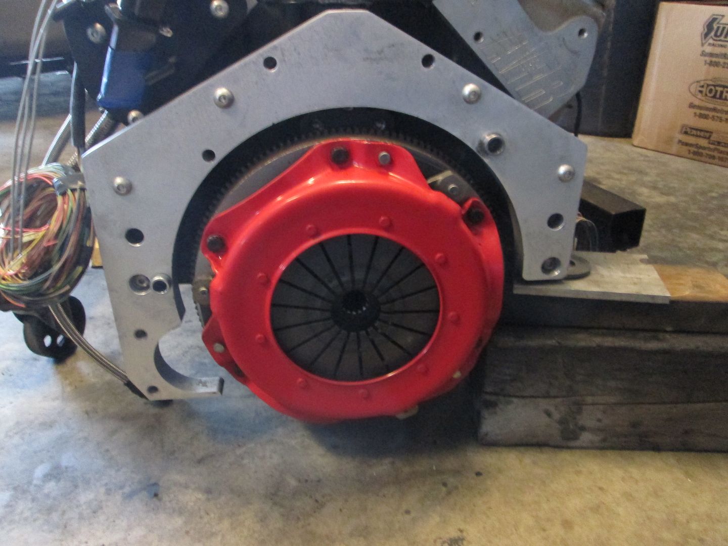
The pressure clutch net pressure plate arrived, so I could start putting the engine and transmission back together:


I smoothed down the rough cut edges of the adapter plate. Here is the first pass on the belt sander:


I finished it with a DA sander and 320 grit so it has a smooth matte look to it:


Once the clutch was installed, I double checked the placement of the clutch fingers and the range of motion for the HTOB. The clutch fingers protruded 2.012" from the bellhousing face and the range of motion for the HTOB was 1.645" to 2.356"... so the HTOB will be nearly centered when installed, which will work just fine.

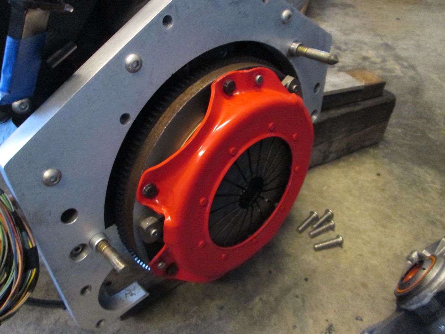
Then it was time to install the transmission. Since I drilled and tapped all the 7/16" holes in the adapter plate to 1/2", I installed a couple of 1/2" alignment bolts to help the input shaft line up and to help me support the transmission while wiggling it:


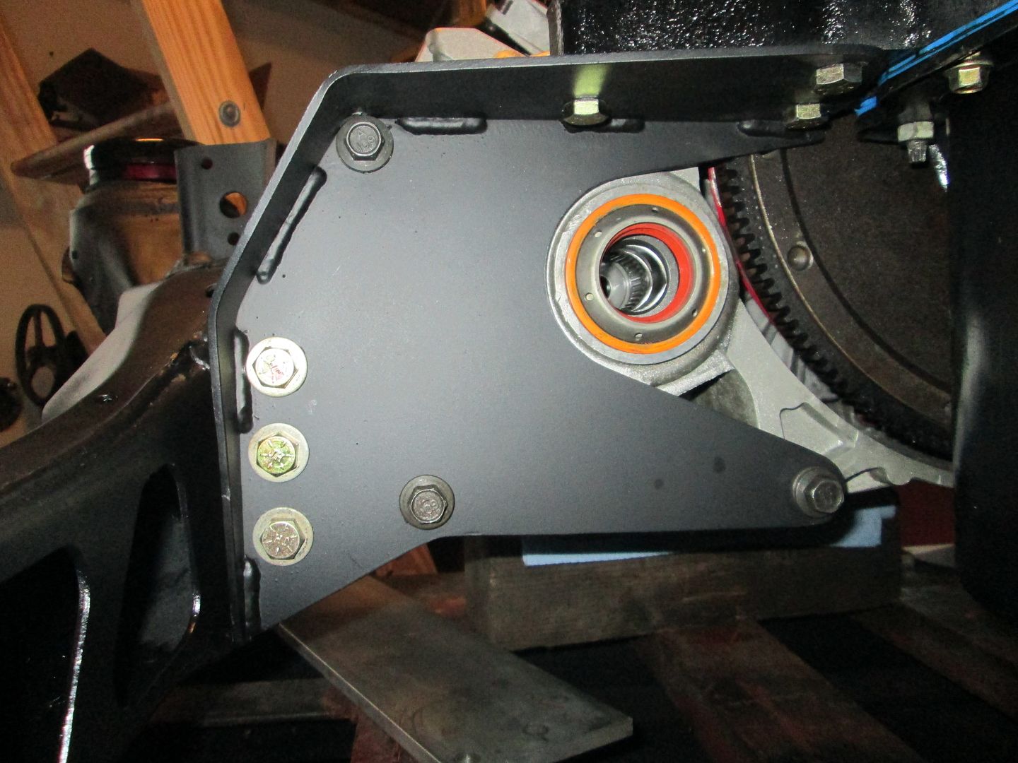
With the transmission connected to the engine once more, I put the drivetrain back on the cradle and tightened all the mounting bolts:


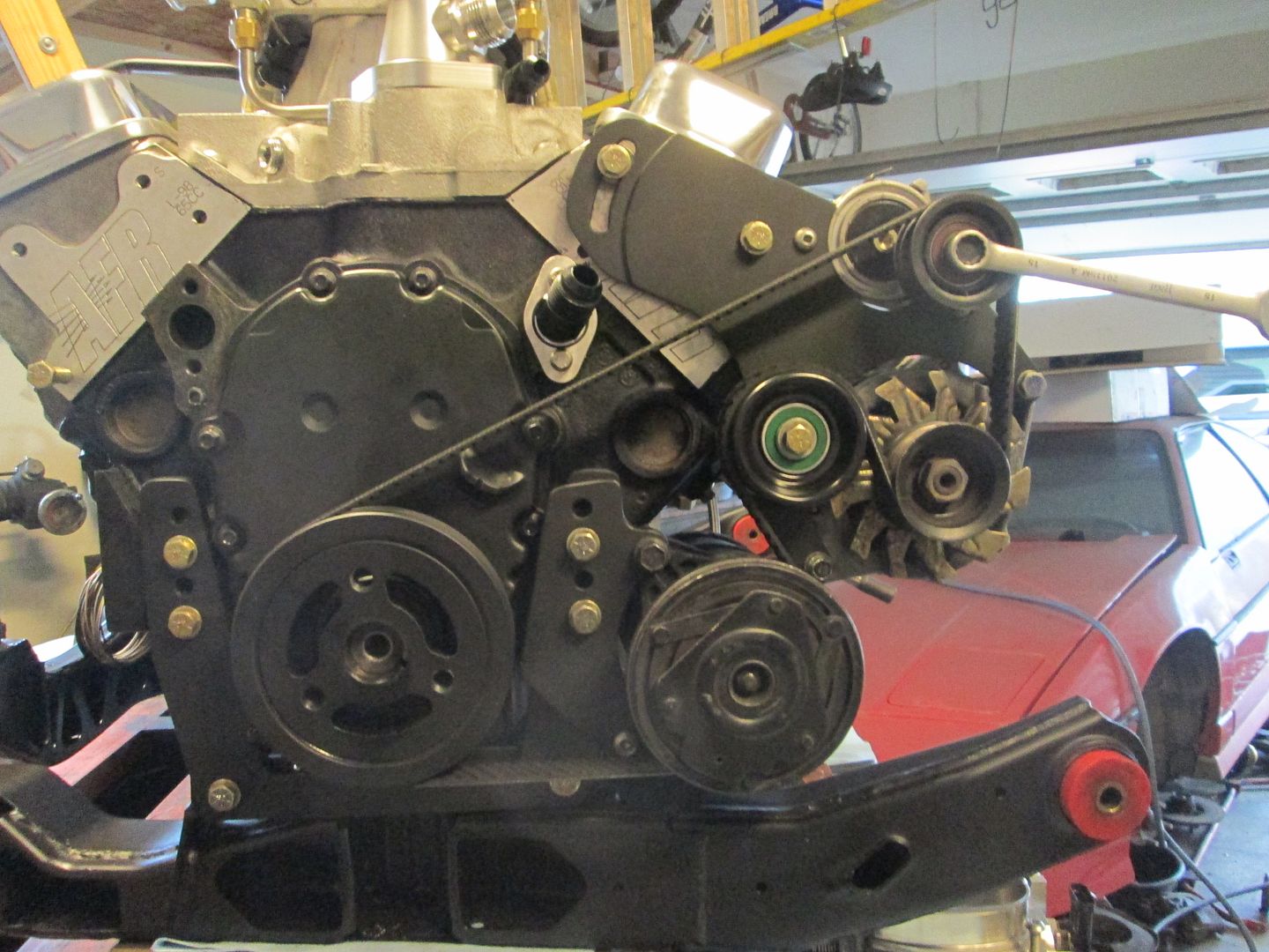
The accessory drive is also back together as well:


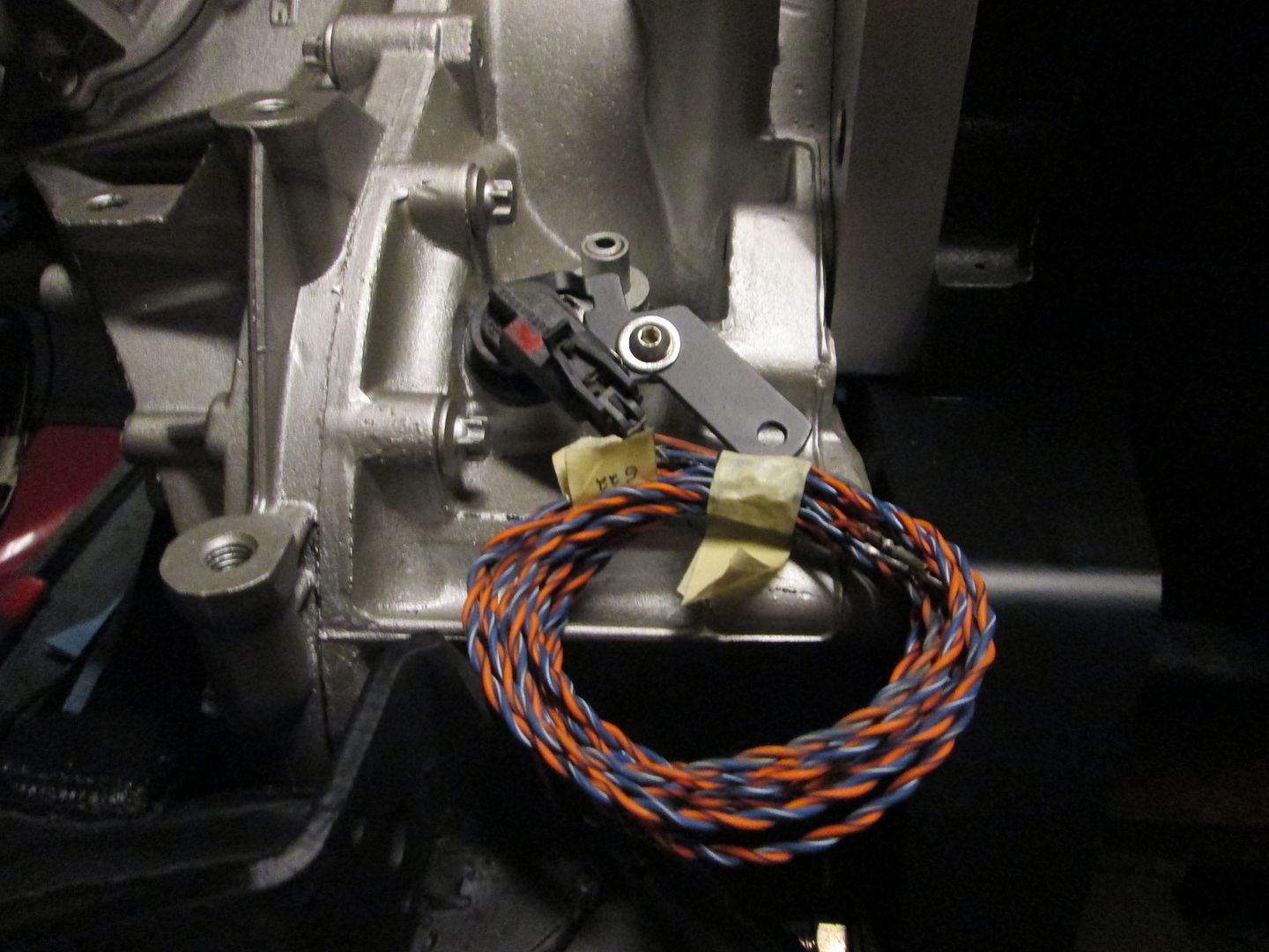
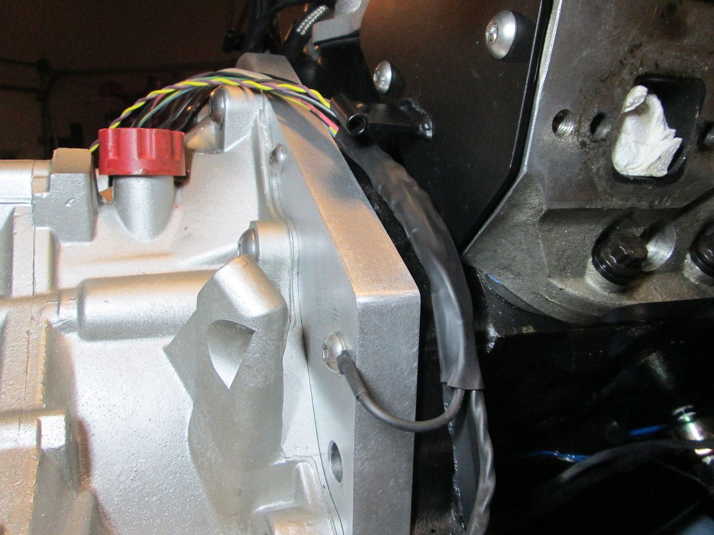
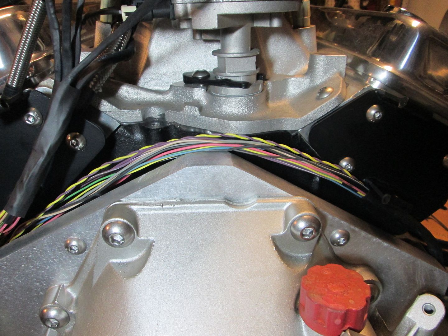
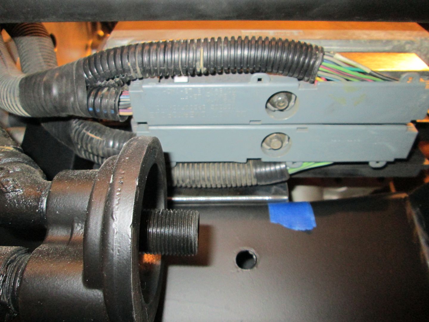
Before I put a lot more of the drivetrain back together, I want to continue looming up the harness wires. From the pile of unneeded connector/wires from the 2006 harness tear down, I found the needed ends with plenty of wire length for the back up lights and VSS on the F23. The VSS uses the ISS (input shaft sensor) connector for the 4L60 (or maybe 4L80) and the backup lights use the connector for the oil level sensor:


The pigtails for the Cam and Crank sensors (both are AC Delco PT420) arrived, so on Sunday I will continue with heat shrinking connector ends and building portions of the harness starting from the various termination points.
IP: Logged
fieroguru
Member
Posts: 12128
From: Champaign, IL
Registered: Aug 2003


Feedback score:    (45)
Leave feedback


Total ratings: 258
Rate this member

Report this Post12-23-2013 07:17 PM Click Here to See the Profile for fieroguruSend a Private Message to fieroguruEdit/Delete MessageReply w/QuoteDirect Link to This Post
More wiring/harness work...

Crankshaft sensor connection:


Ground, O2 sensor, Knock Sensor - Bank 2, ECM temp sensor & Temp gauge connections:


VSS and Reverse Light, and Ground connections:


Bank 2 side of the harness going under the coils and following the bellhousing to the other side:


Also finished up the sub loom from the top side. All 8 Injectors, MAP Sensor, TPS Sensor, IAC Sensor, Camshaft Position Sensor, MAF Sensor wires coming down and will join the main harness at the bellhousing and follow it under the Bank 1 coils:


I still need to work on the Bank 1 side (Alternator, AC, Knock Sensor Bank 1, O2 sensor Bank 1, Oil Pressure Sensor, & Starter) and the wires for the 8 coils.

The wideband harness will be loomed up separately so it can be easily removed/replaced at a later date. It will be in shrink wrap its entire length from the O2 sensor to the passenger compartment.

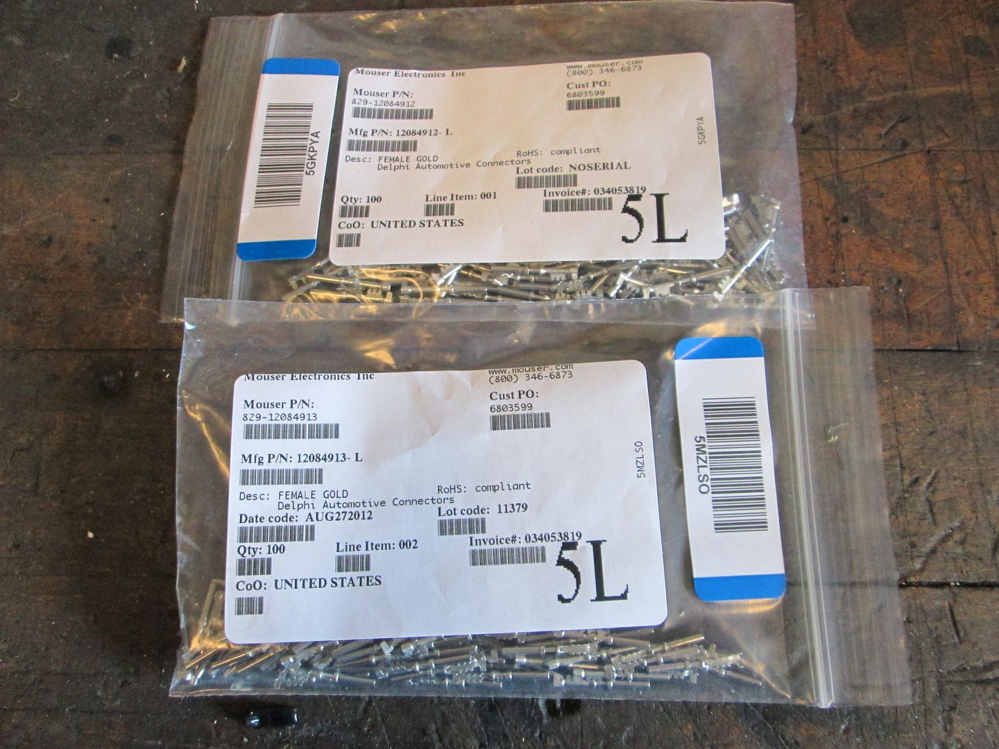
Ordered the new O2 sensors, all the ECM pins, the GM ECM holder and a few other parts today.

Here is a picture with the rear header on:
IP: Logged
sleevePAPA
Member
Posts: 776
From:
Registered: Jan 2013


Feedback score: N/A
Leave feedback

Rate this member

Report this Post12-23-2013 07:54 PM Click Here to See the Profile for sleevePAPASend a Private Message to sleevePAPAEdit/Delete MessageReply w/QuoteDirect Link to This Post
Still watching, nice work!
IP: Logged
ericjon262
Member
Posts: 3082
From: everywhere.
Registered: Jan 2010


Feedback score:    (10)
Leave feedback


Total ratings: 66
Rate this member

Report this Post12-23-2013 11:50 PM Click Here to See the Profile for ericjon262Send a Private Message to ericjon262Edit/Delete MessageReply w/QuoteDirect Link to This Post
wow, just realized you must have spent a fortune on all of though allen head fasteners....
IP: Logged
fieroguru
Member
Posts: 12128
From: Champaign, IL
Registered: Aug 2003


Feedback score:    (45)
Leave feedback


Total ratings: 258
Rate this member

Report this Post12-24-2013 09:08 AM Click Here to See the Profile for fieroguruSend a Private Message to fieroguruEdit/Delete MessageReply w/QuoteDirect Link to This Post
 
quote
Originally posted by ericjon262:

wow, just realized you must have spent a fortune on all of though allen head fasteners....


The stainless button heads are a sickness... I really like using them on my swaps in the visible low load areas. I have spent about $150 in stainless bolts for this swap, but I don't consider that to be terribly expensive, especially given all the other hardware on this swap.
IP: Logged
fieroguru
Member
Posts: 12128
From: Champaign, IL
Registered: Aug 2003


Feedback score:    (45)
Leave feedback


Total ratings: 258
Rate this member

Report this Post12-24-2013 05:28 PM Click Here to See the Profile for fieroguruSend a Private Message to fieroguruEdit/Delete MessageReply w/QuoteDirect Link to This Post

fieroguru

12128 posts
Member since Aug 2003
The front side harness sub loom is nearly complete...

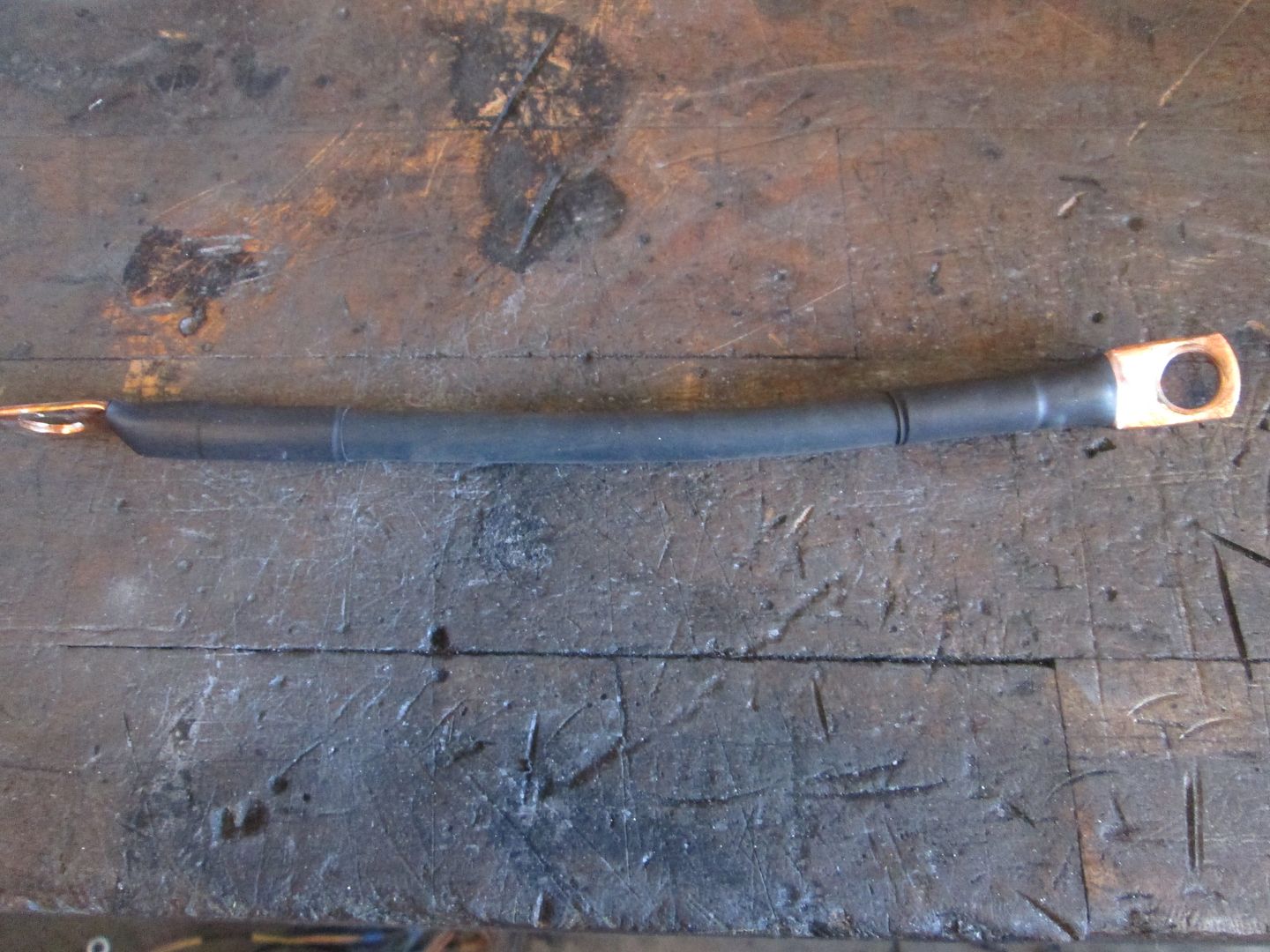
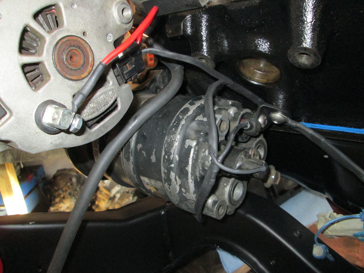
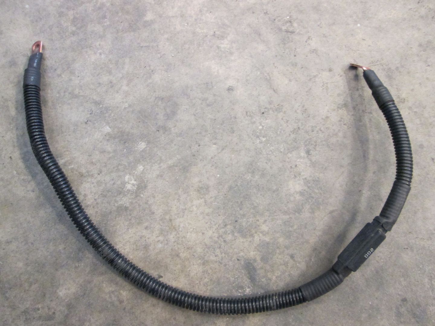
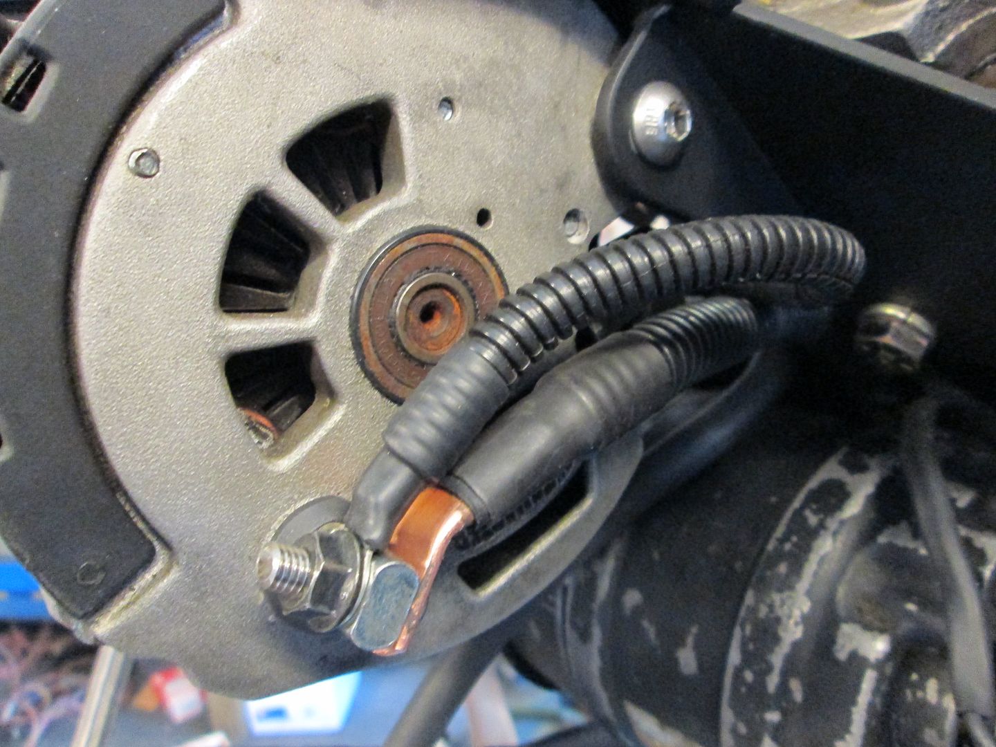
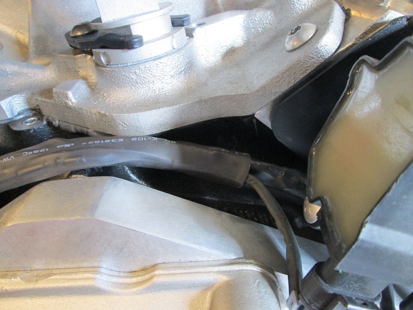
Alternator ground cable (just in case it doesn't ground well through the bracket):


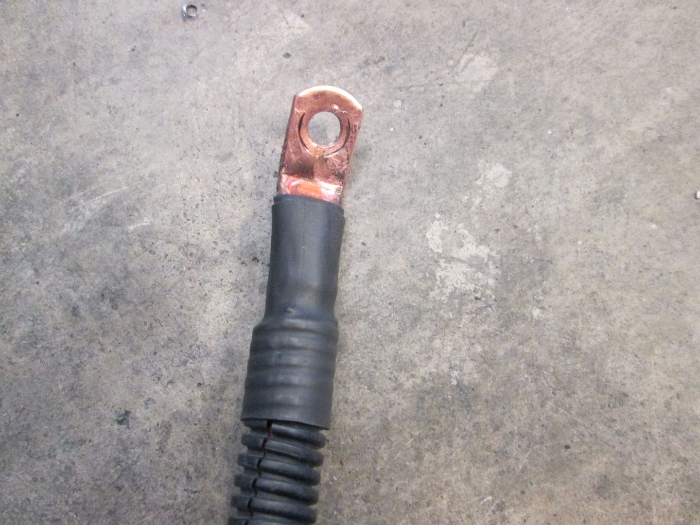
The main engine to chassis ground cable connection (shared with the alternator ground):


I will weld a stainless bolt to the chassis for this end to attach to:


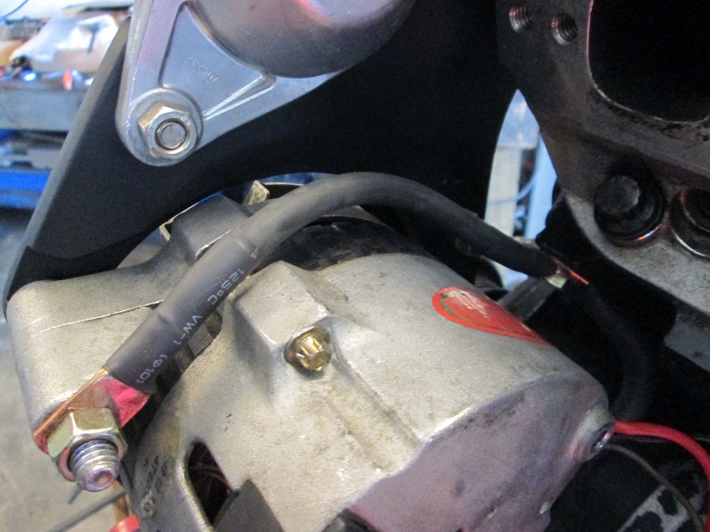
A/C and alternator connections and the front ground (main power cable will be shown later):


O2, Knock, Oil pressure, and starter switch connections:


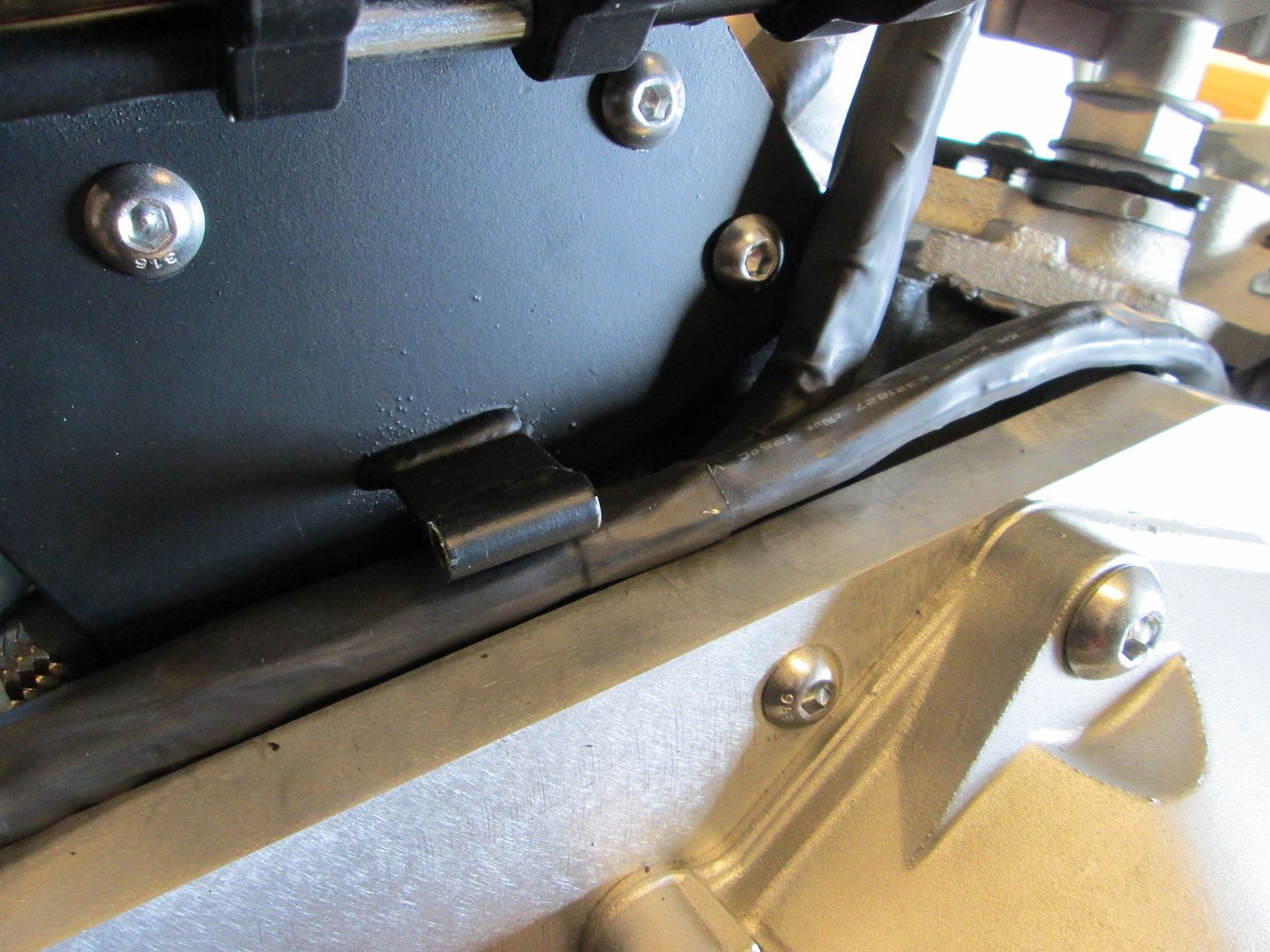
Front loom routed to bellhousing area:


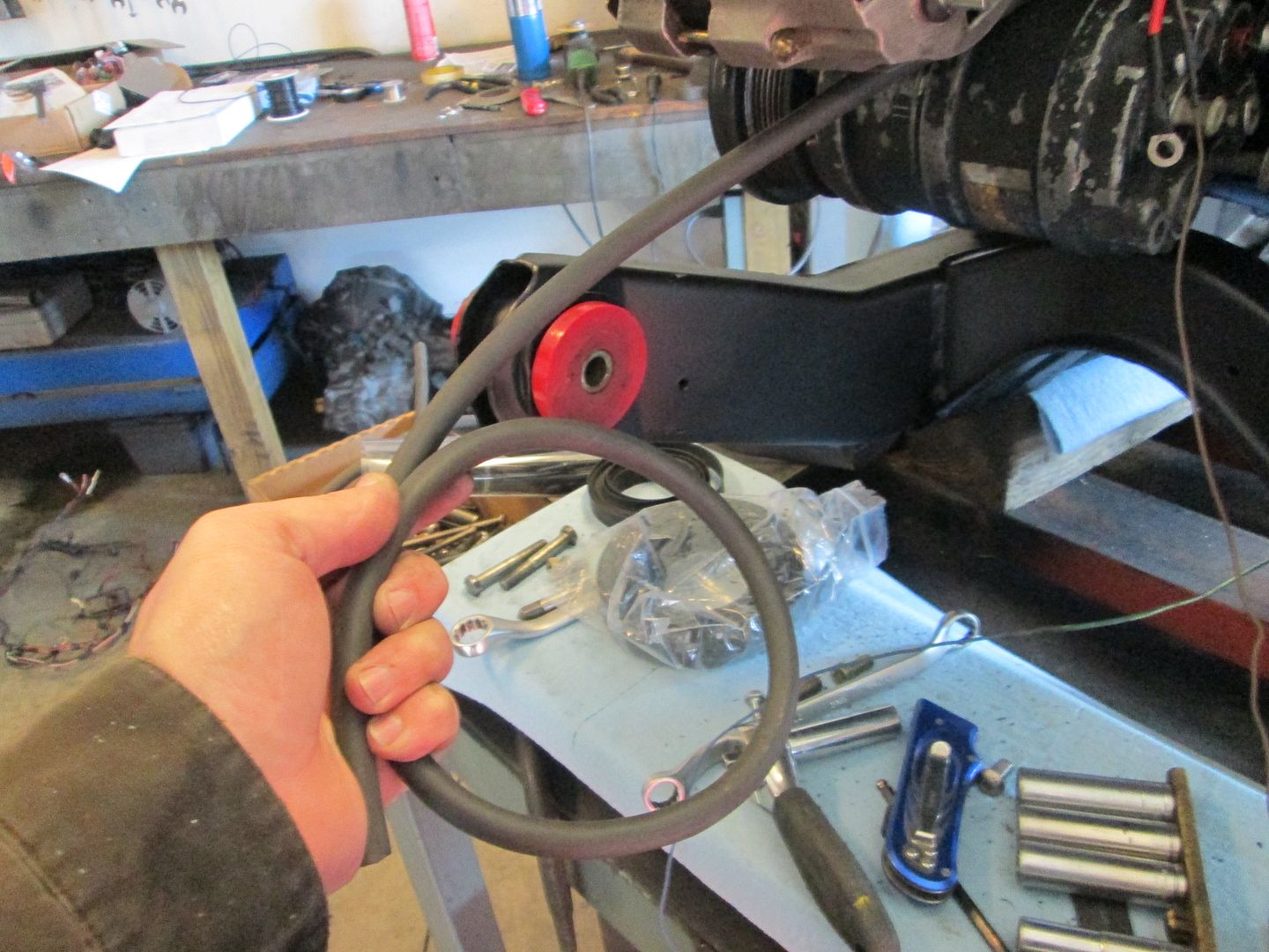
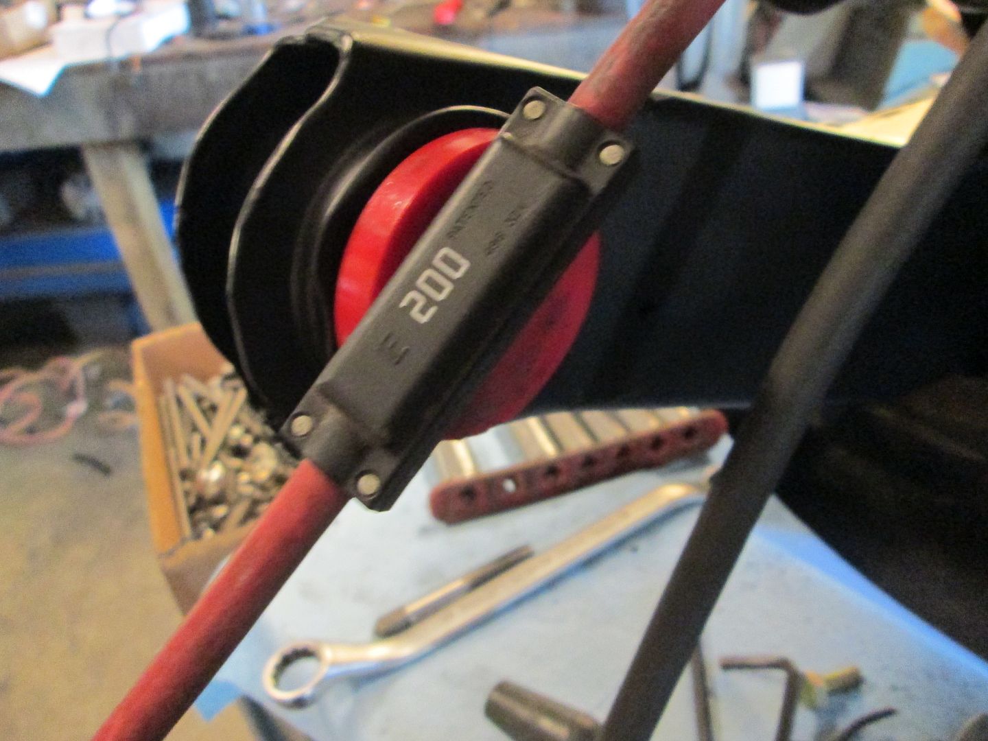
Main power cable from alternator to starter (stock LS4 alternator to starter cable with integrated 200 amp fusible link). This will be ran in a corrugated plastic cable sleeve to help protect it from rubbing.:


I also mounted the coils:

IP: Logged
Trinten
Member
Posts: 1352
From: Mebane, N.C.
Registered: Sep 2008


Feedback score:    (8)
Leave feedback

Rate this member

Report this Post12-28-2013 10:34 PM Click Here to See the Profile for TrintenSend a Private Message to TrintenEdit/Delete MessageReply w/QuoteDirect Link to This Post
 
quote
Originally posted by Blacktree:

Welcome to the Construction Zone. Cool build, by the way.


Thanks BlackTree,

FieroGuru has been great about sending me PMs with updates. And recently he had mentioned he was going to have some more stuff up in the thread. I realized that I hadn't gotten a notice of posts being made to the thread. So I found my old thread, and was shocked when I saw it said "Thread Closed" -- I was like "What happened?!" then saw the link about it being moved here!! lol

Everything looks incredible FieroGuru, thank you so much for all the attention to detail you've put into this.

I think the alternator I have on there puts out 230 Amps, will that cause problems with the 200 amps fusible link you installed?

Seriously pumped up about this!

[This message has been edited by Trinten (edited 12-28-2013).]

IP: Logged
PFF
System Bot
fieroguru
Member
Posts: 12128
From: Champaign, IL
Registered: Aug 2003


Feedback score:    (45)
Leave feedback


Total ratings: 258
Rate this member

Report this Post12-29-2013 03:20 PM Click Here to See the Profile for fieroguruSend a Private Message to fieroguruEdit/Delete MessageReply w/QuoteDirect Link to This Post
 
quote
Originally posted by Trinten:
Everything looks incredible FieroGuru, thank you so much for all the attention to detail you've put into this.

I think the alternator I have on there puts out 230 Amps, will that cause problems with the 200 amps fusible link you installed?

Seriously pumped up about this!


Thanks!

The alternator is part # 47802 and should be a 140 amp alternator, unless you had a local shop do the upgrade to 230 amp. Fully loaded LS4 cars come with a 135 amp alternator, so 140 should be fine for this swap.

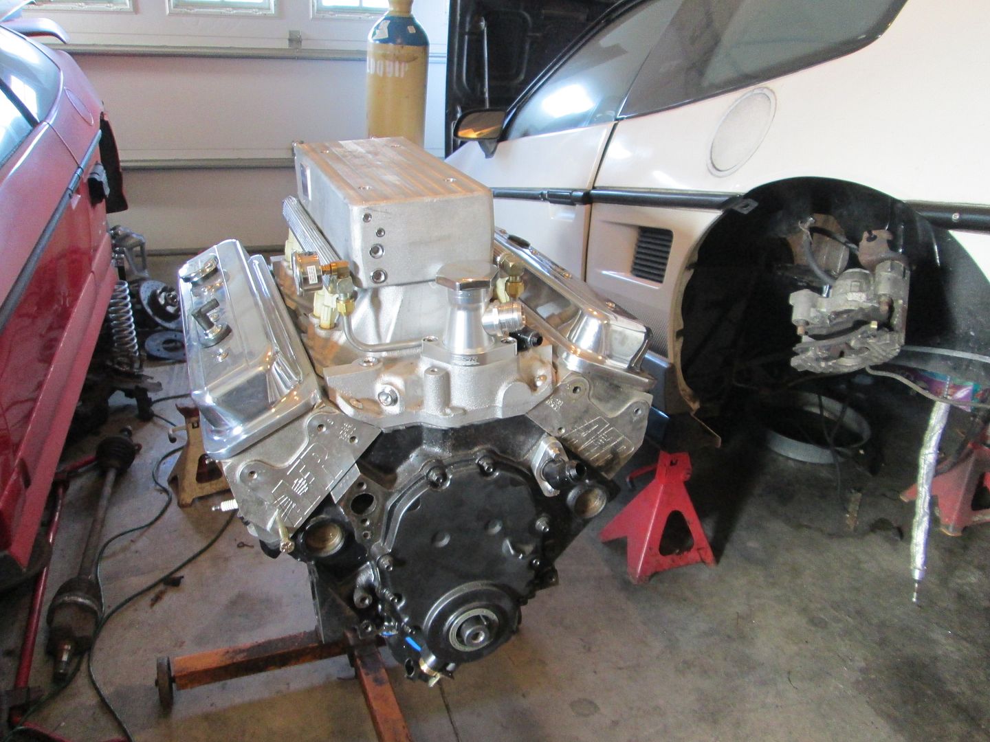
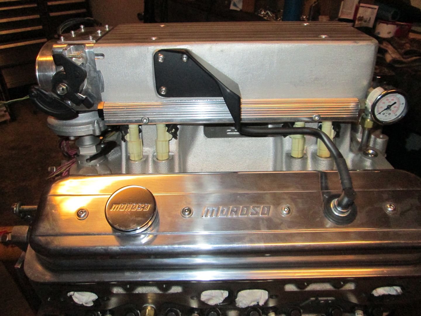
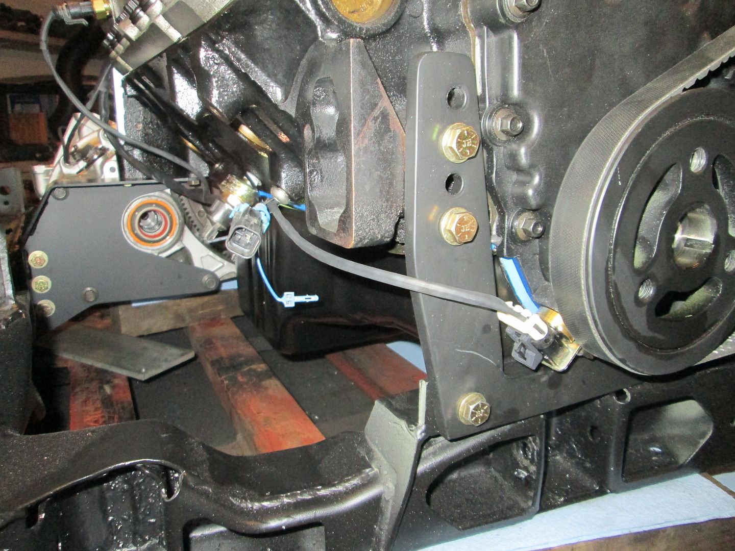
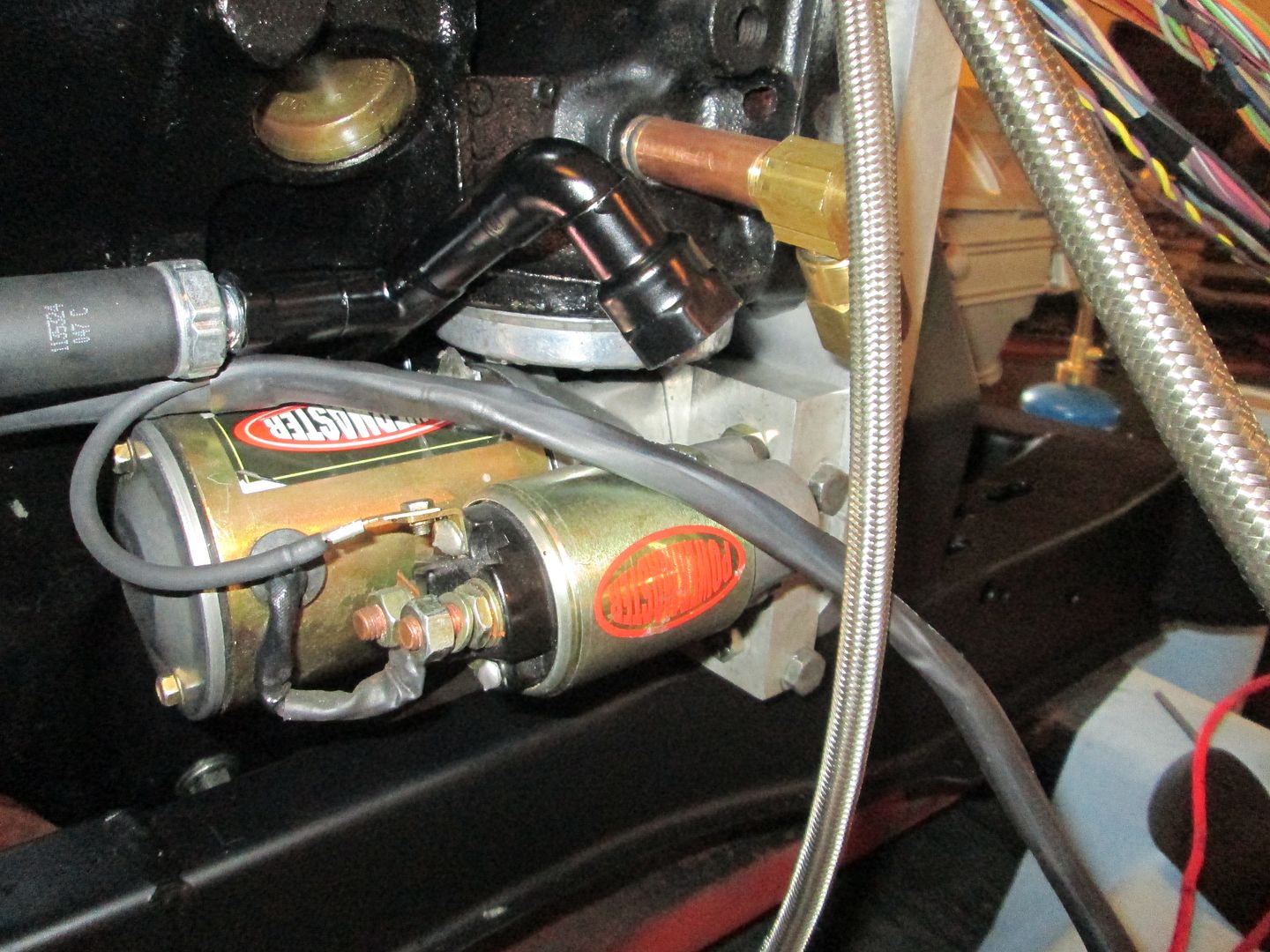
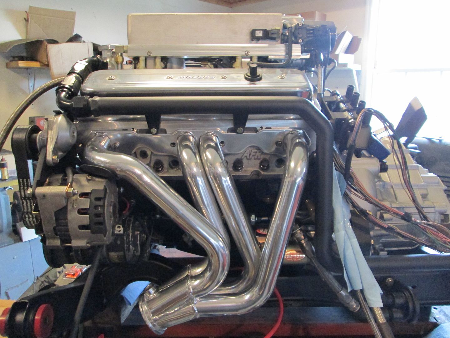
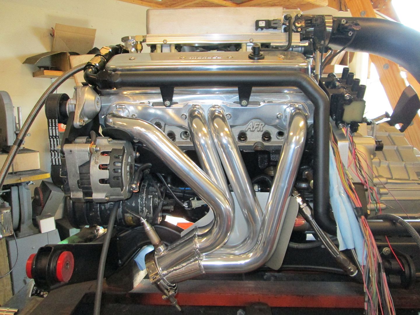
Put the oil filter housing back on:


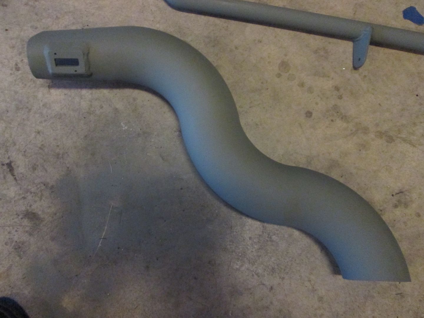
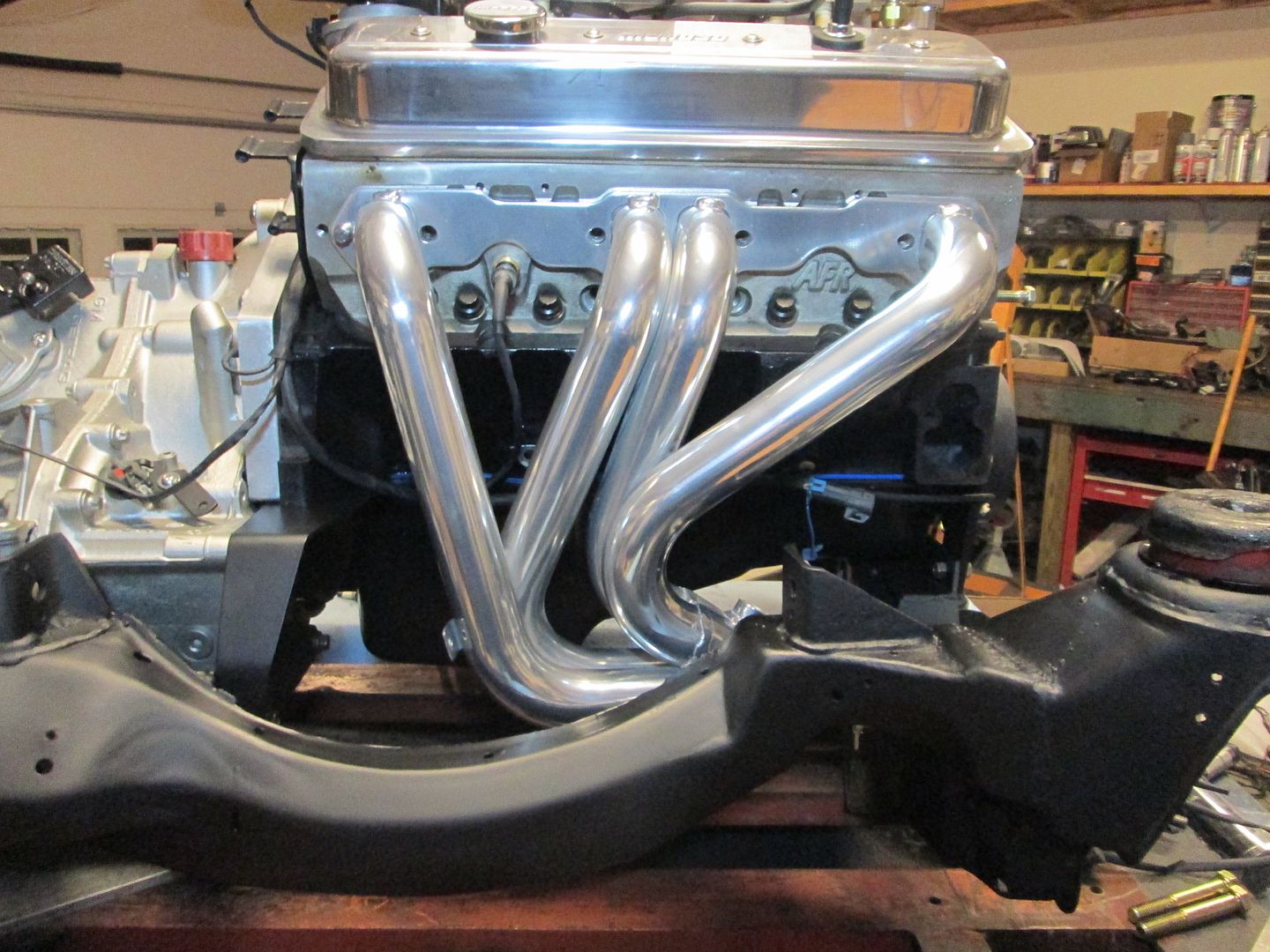
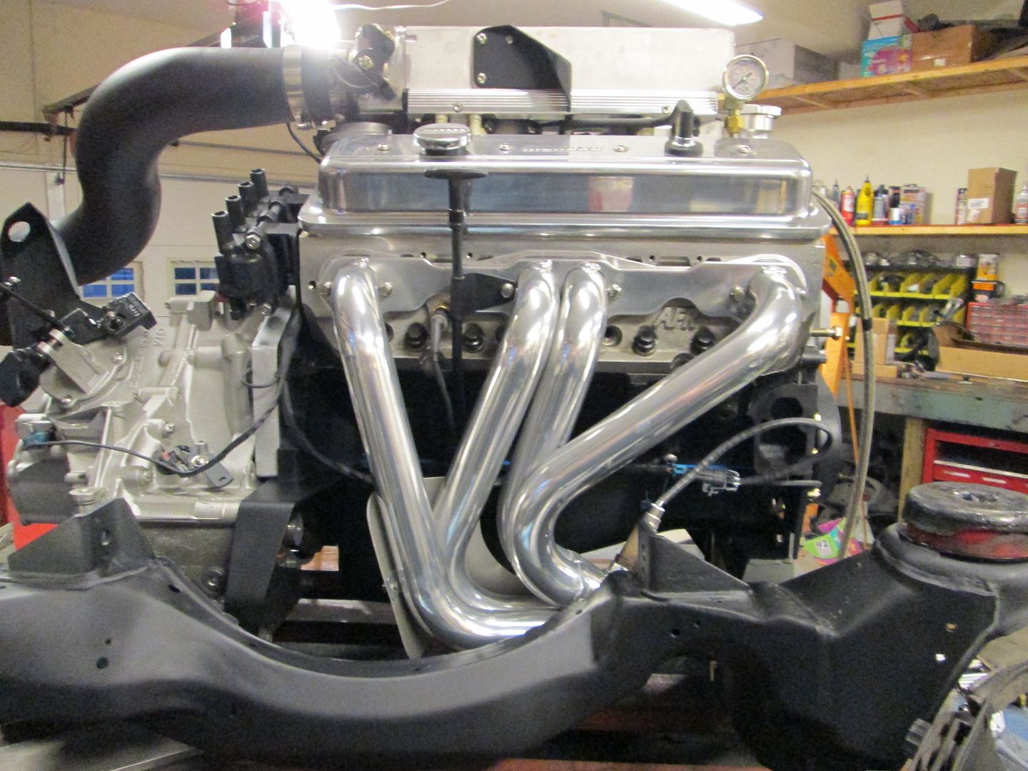
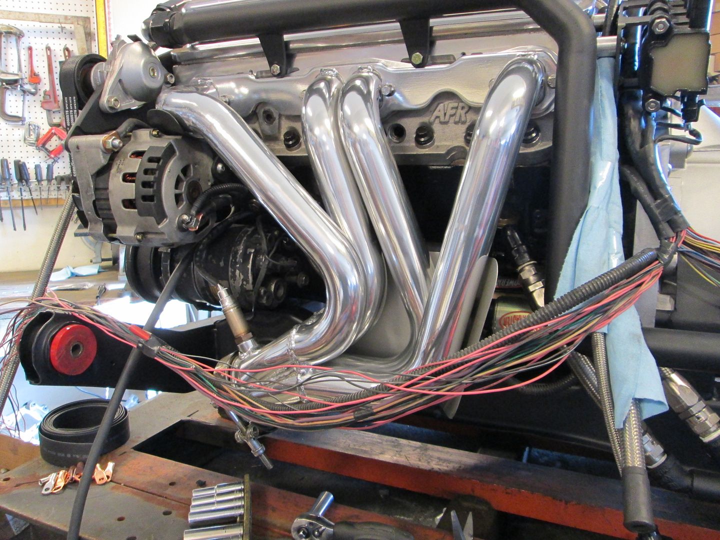
Then the coolant crossover pipe and front header:


Also the 4" air intake tube to verify the MAF wires are long enough:


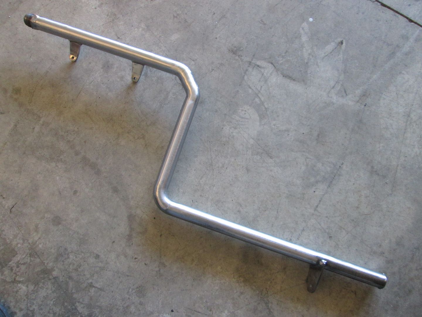
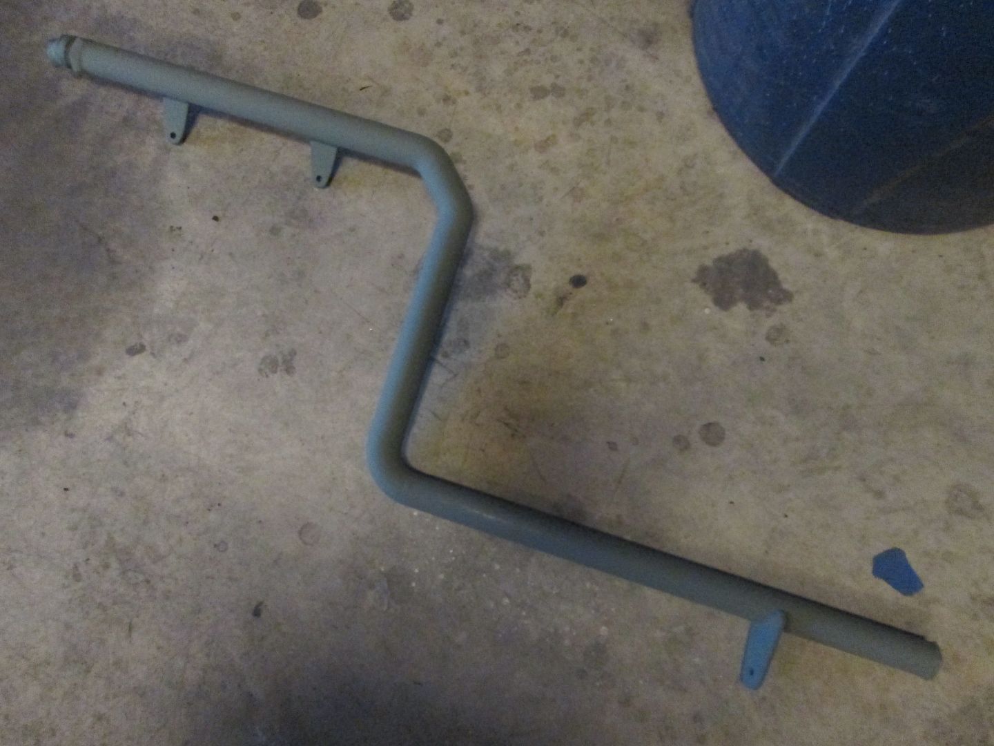
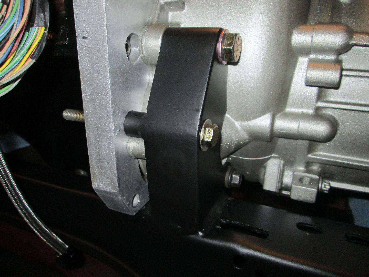
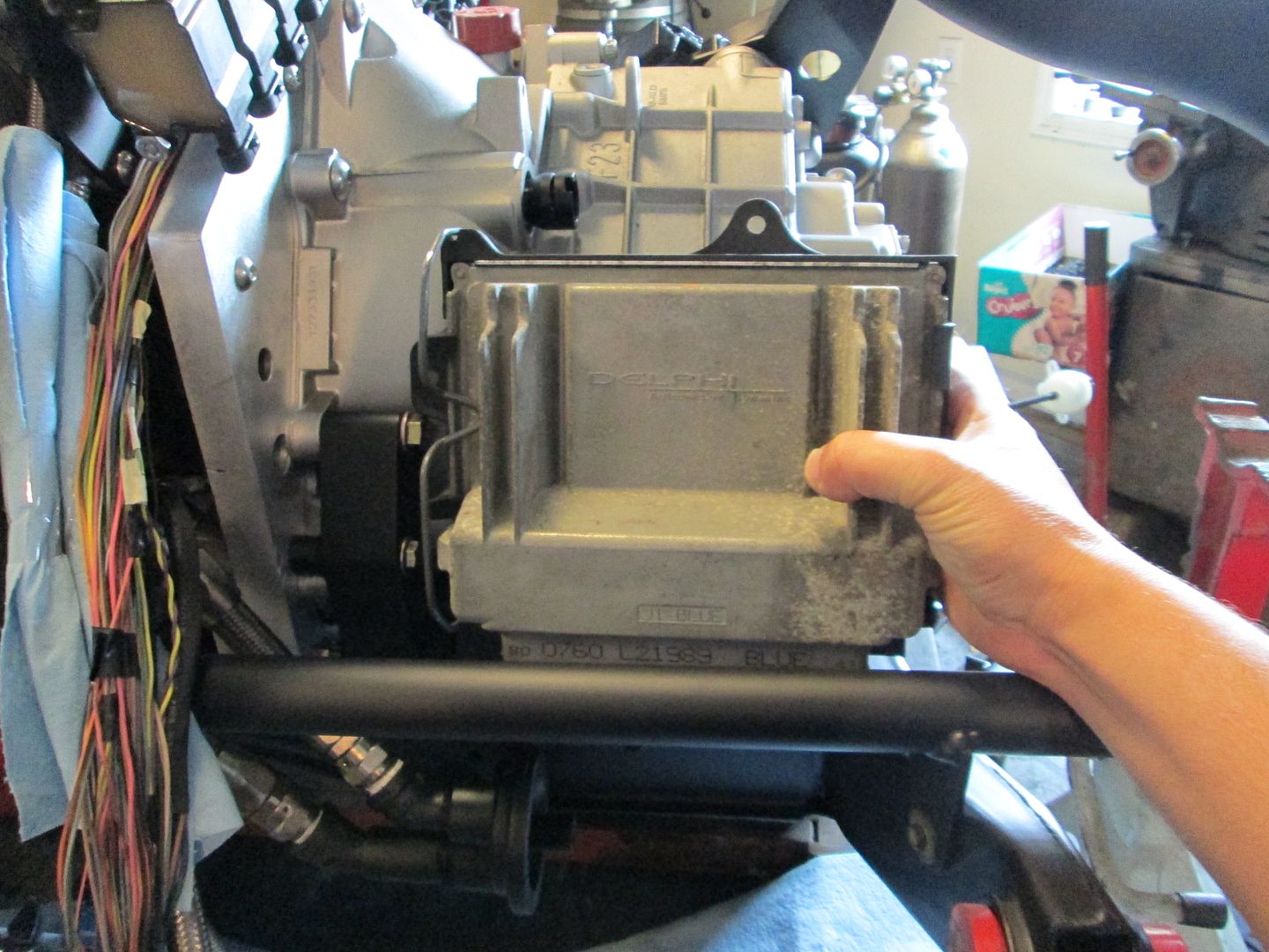
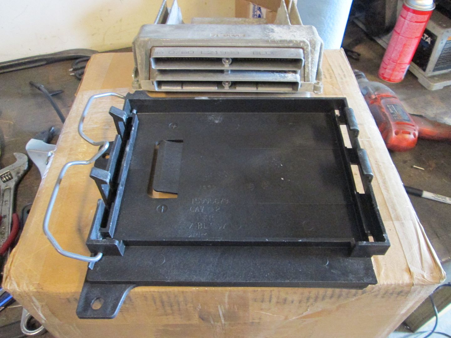
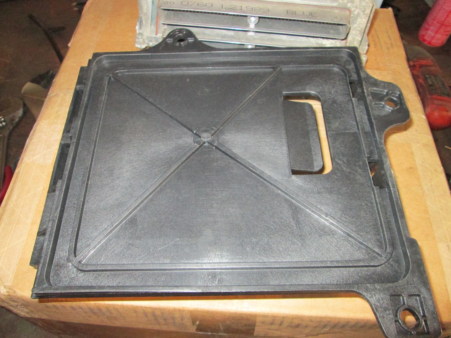
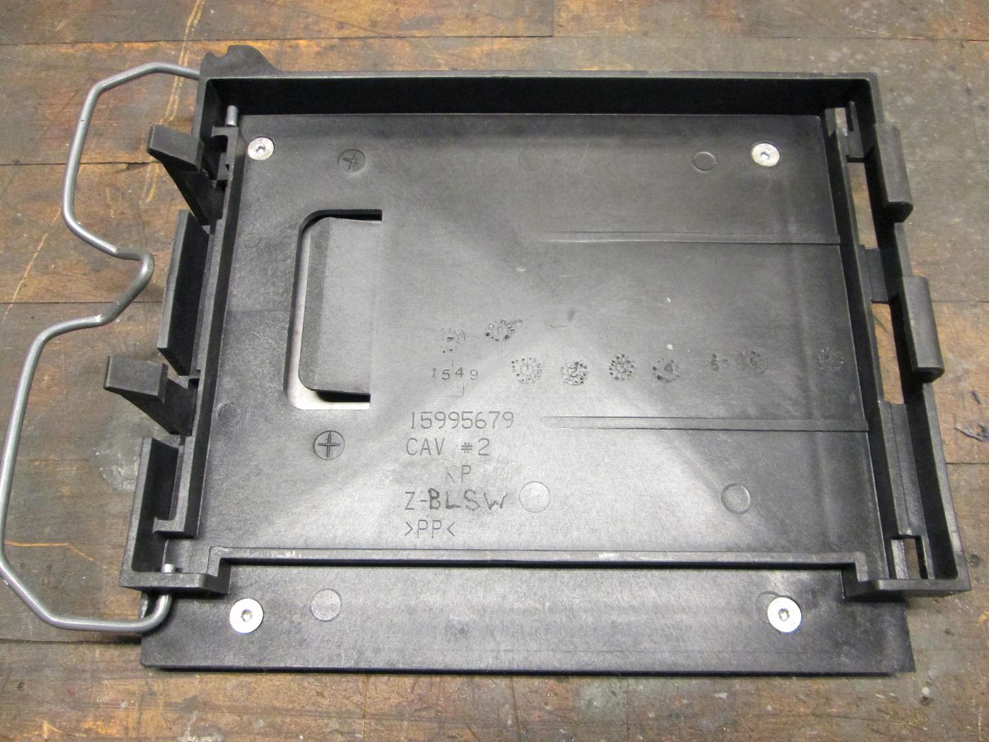
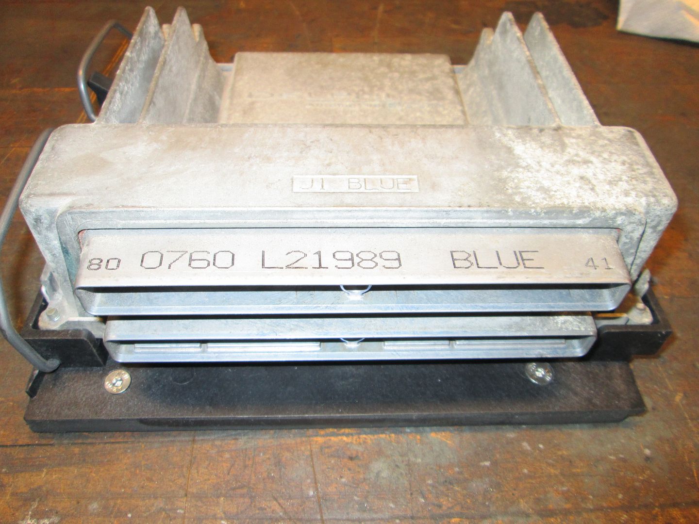
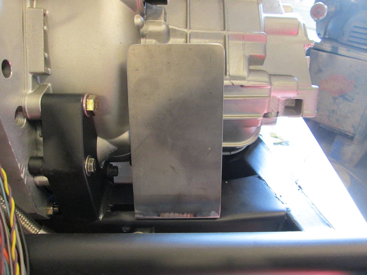
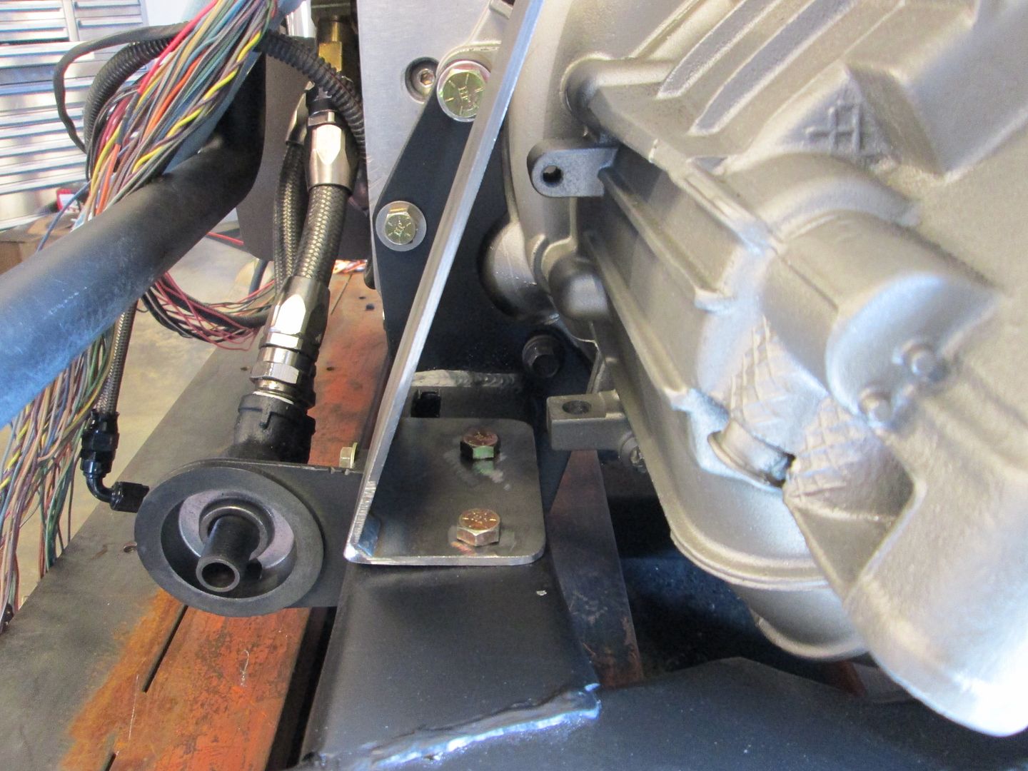
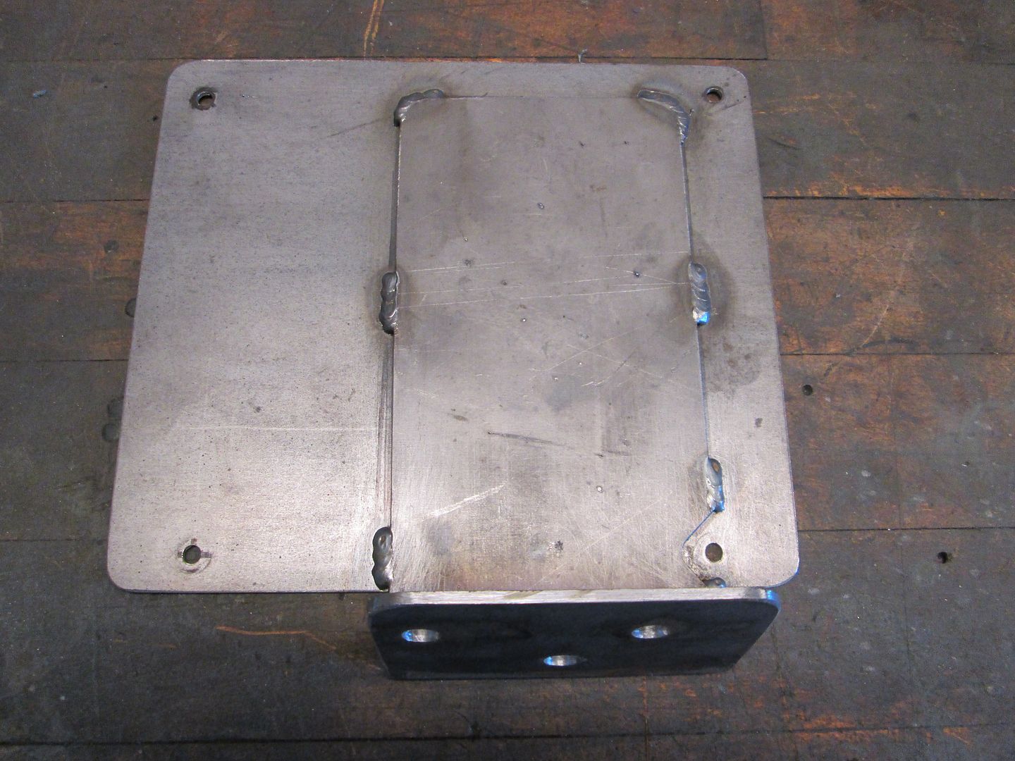
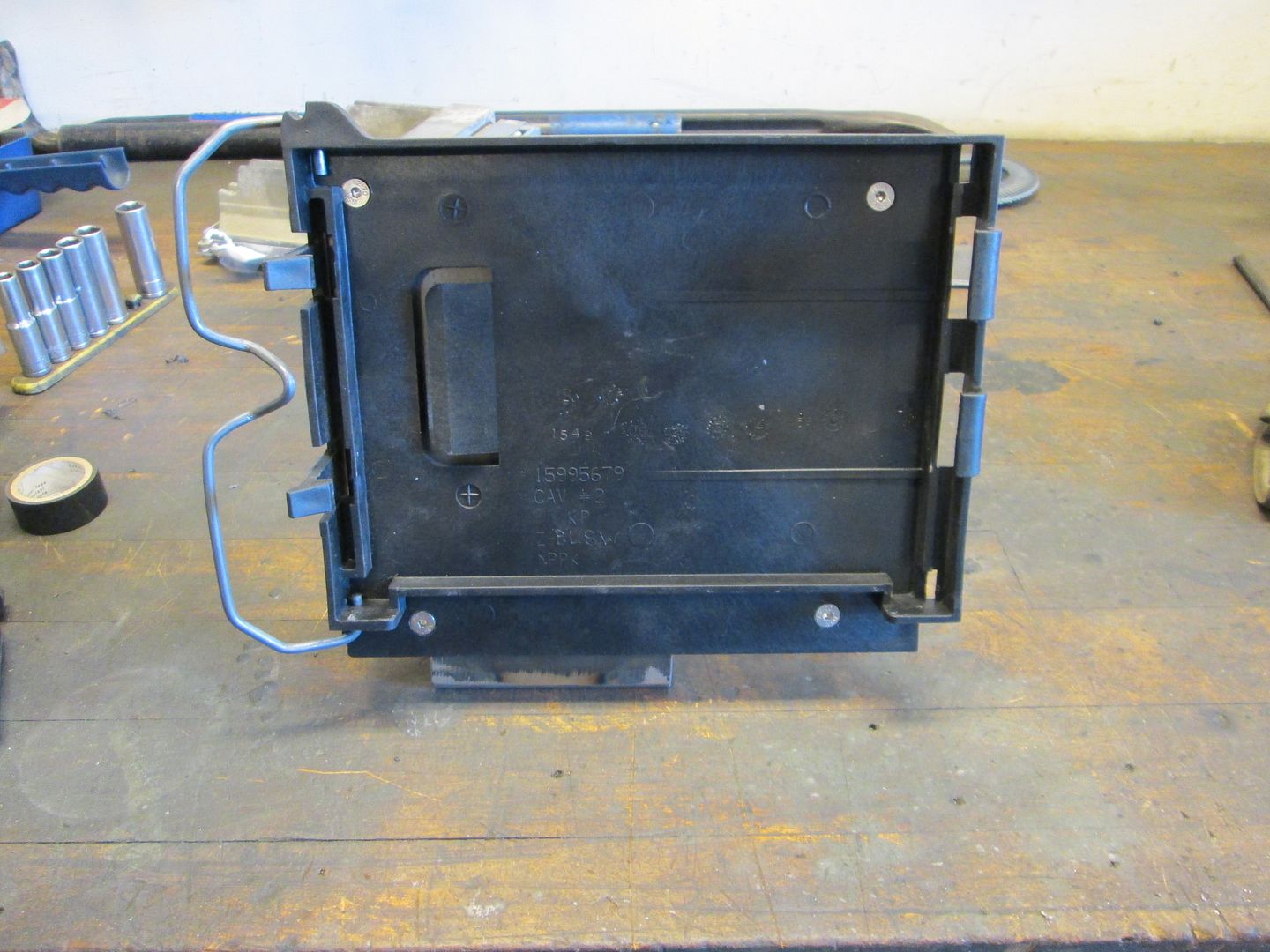
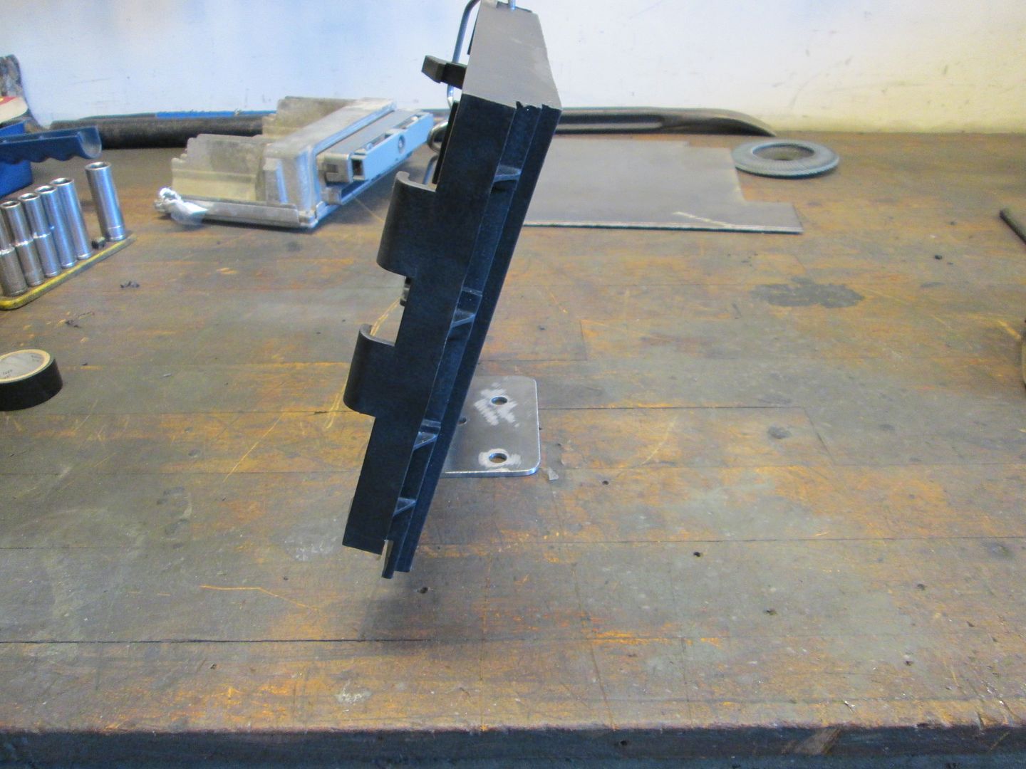
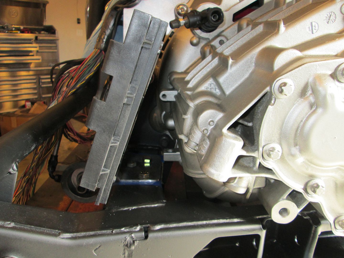
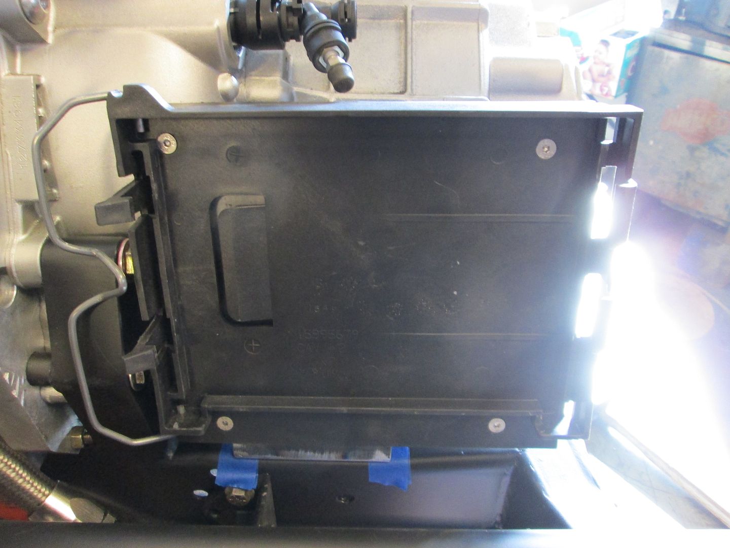
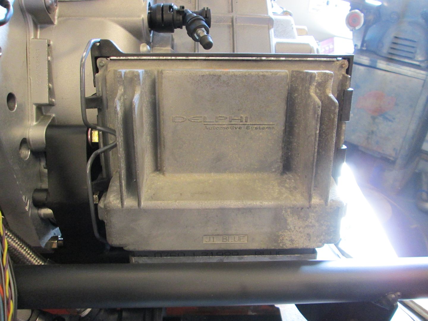
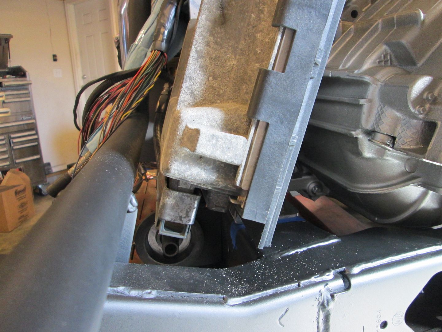
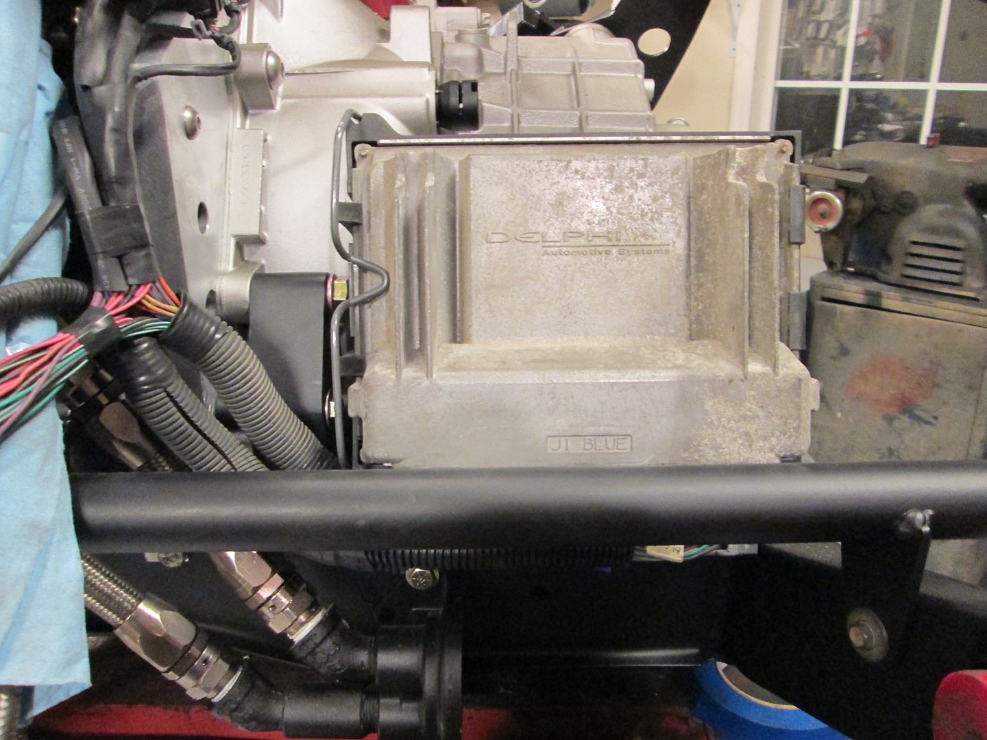
This looks like a good place for the ECM. It will be mostly hidden from view and away from any significant heat sources. Just need to make a support bracket that will attach to the cradle via the stock transmission mount holes:


To hold the ECM, a truck ECM holder is used. Its pretty much flat and I can cut off all the stock mounting tabs and bolt it to a custom mounting bracket.


After Monday I will be all caught up on packages to ship and other customer orders and will have another 2 days off for the holiday to get more done on this.
IP: Logged
Trinten
Member
Posts: 1352
From: Mebane, N.C.
Registered: Sep 2008


Feedback score:    (8)
Leave feedback

Rate this member

Report this Post12-29-2013 05:02 PM Click Here to See the Profile for TrintenSend a Private Message to TrintenEdit/Delete MessageReply w/QuoteDirect Link to This Post
Thank you for the catch! You are right, it was a 140 amp Alternator. I don't know why I was thinking 230.

Looks so fricking sweet!! I really like how the black and silver/chrome is turning out.

Even though the paint is years from being done, I think I'm going to spring for a car cover now... help reduce the amount of leaves and crap that'll get down through the vents and make it look lousy -- I'm sure you found a few pounds of pine needles floating around everything.

Thanks again!!
IP: Logged
fieroguru
Member
Posts: 12128
From: Champaign, IL
Registered: Aug 2003


Feedback score:    (45)
Leave feedback


Total ratings: 258
Rate this member

Report this Post01-01-2014 06:05 PM Click Here to See the Profile for fieroguruSend a Private Message to fieroguruEdit/Delete MessageReply w/QuoteDirect Link to This Post
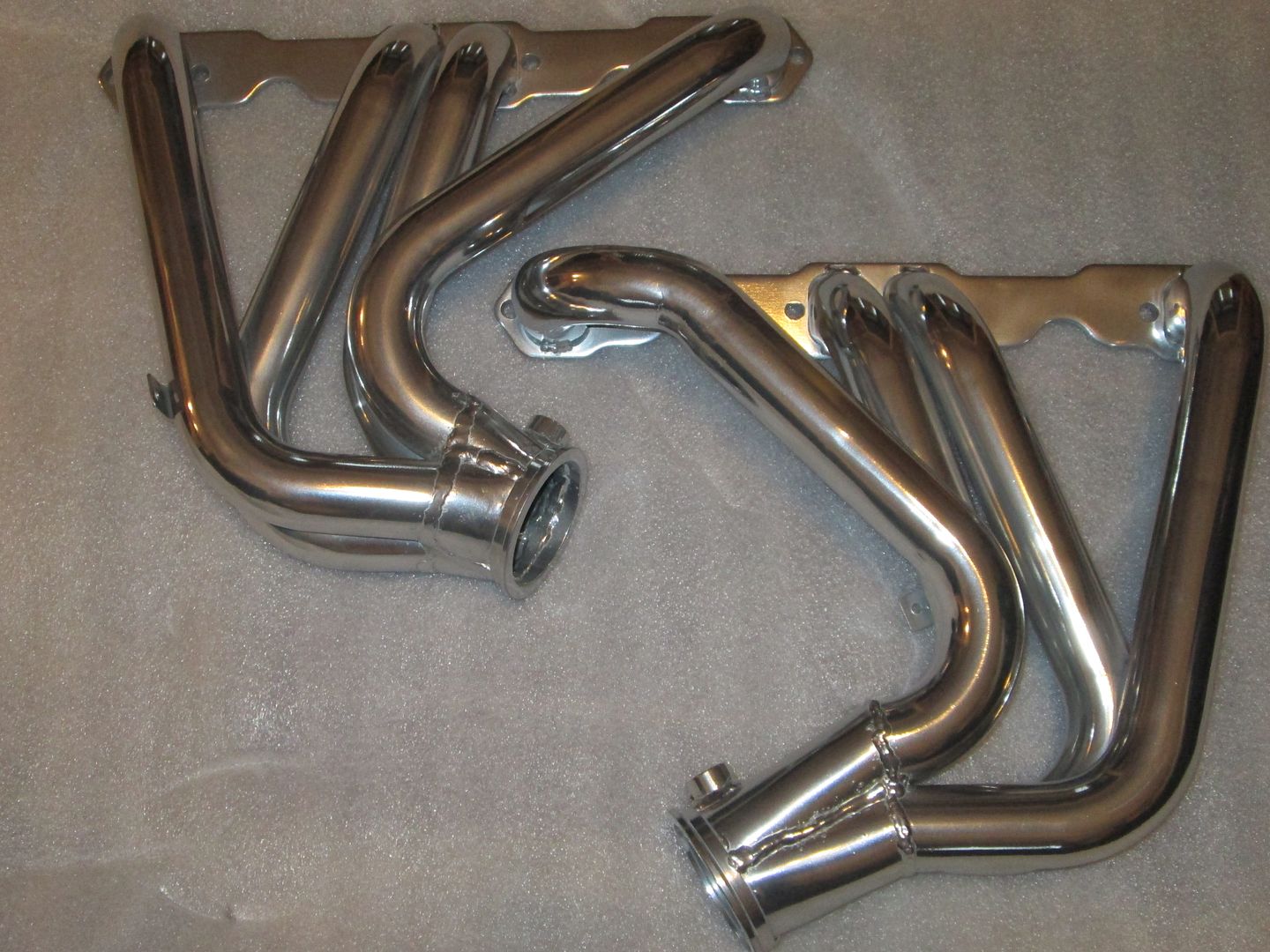
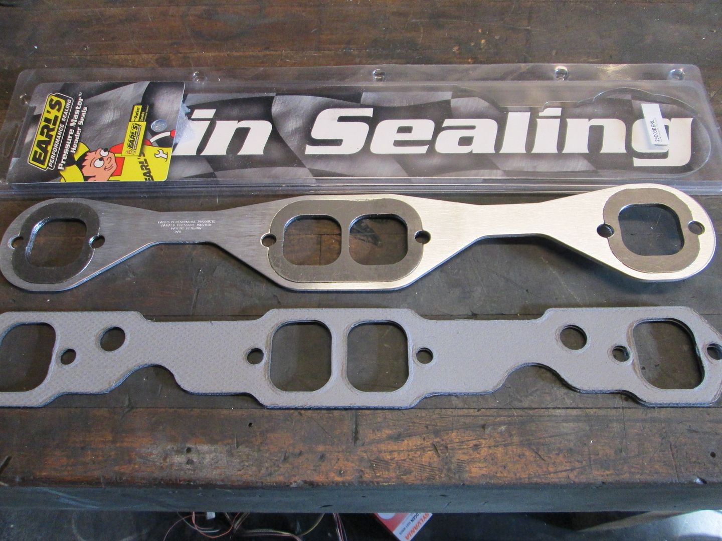
A few parts have shown up since the last update.
The exhaust gaskets. These have a removable gasket around the ports, so we will see how they do.


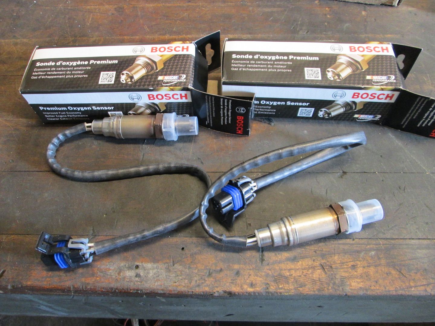
LS1 Camaro heated O2 sensors:


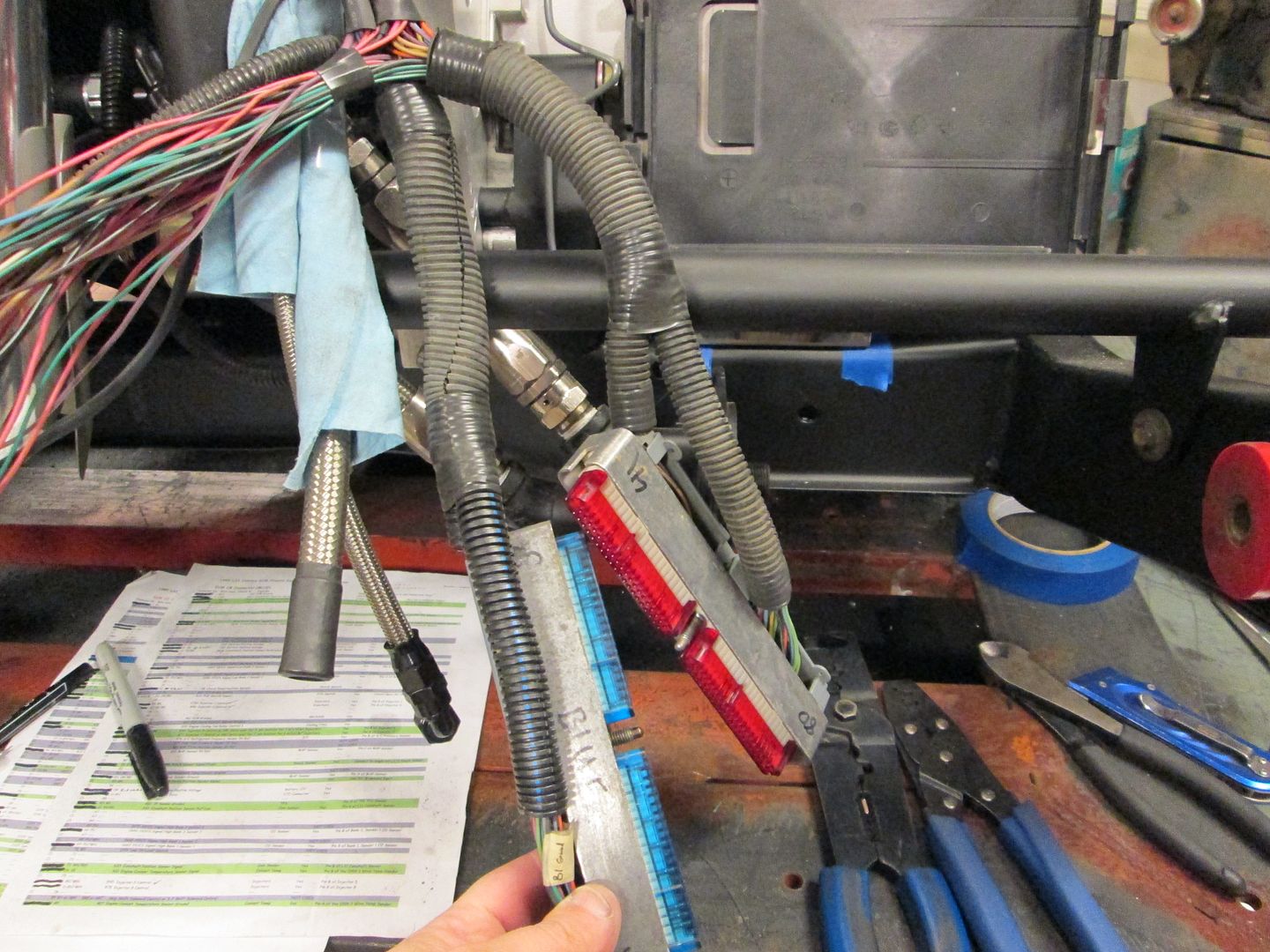
Pins for the ECM terminals:


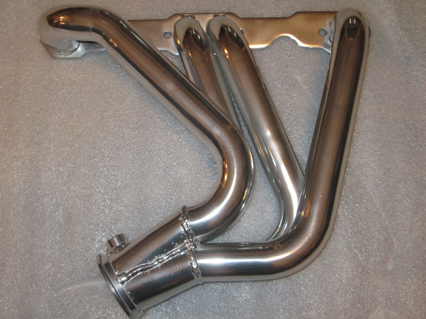
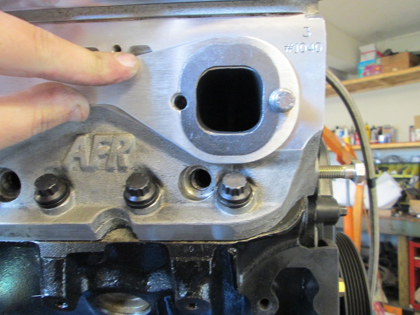
I test fitted the header gaskets on the rear of the engine. The headers have a larger (taller) taller opening.


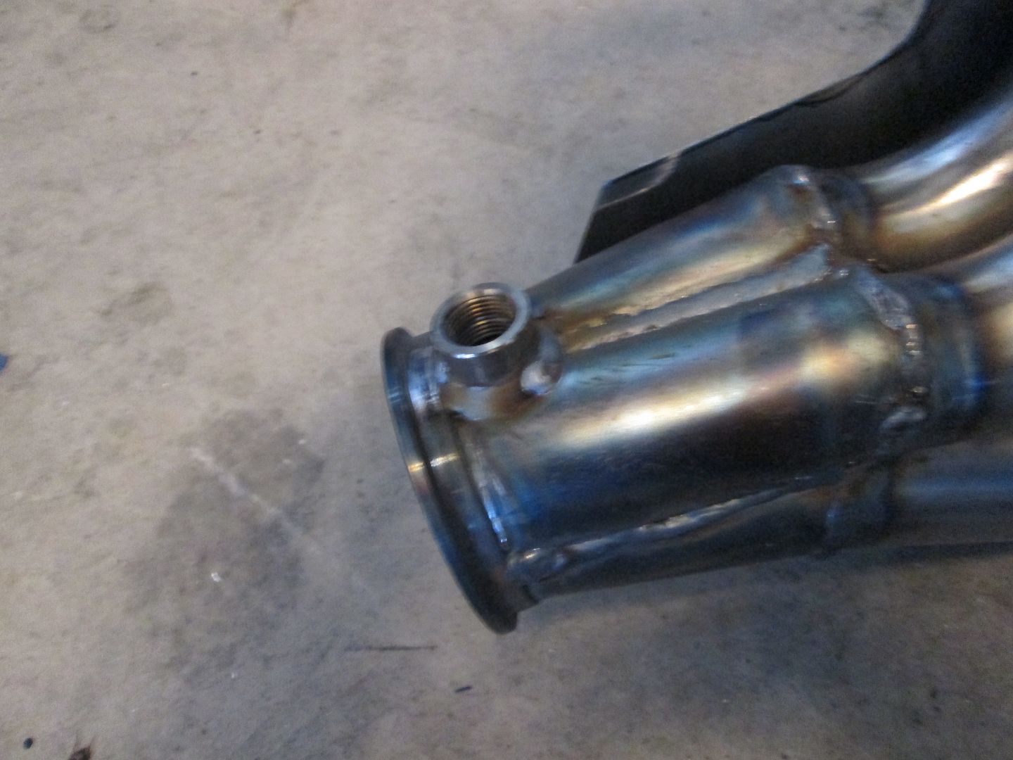
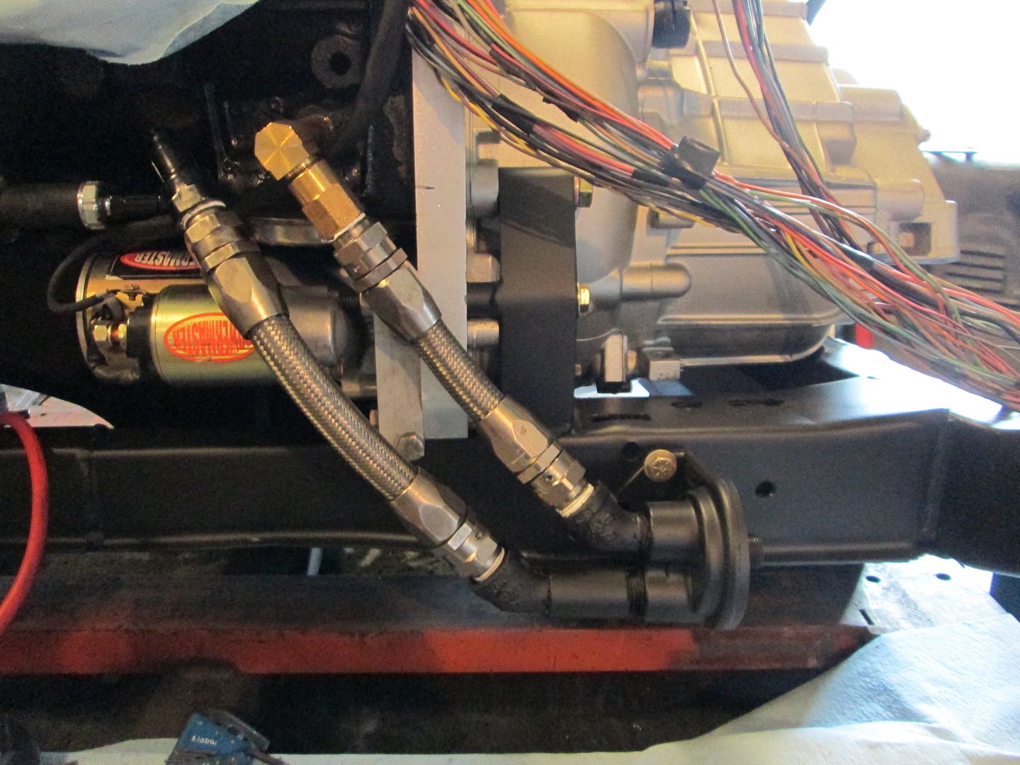
Then the gaskets, header, heat shield, O2 sensor and V-band clamp were all installed:


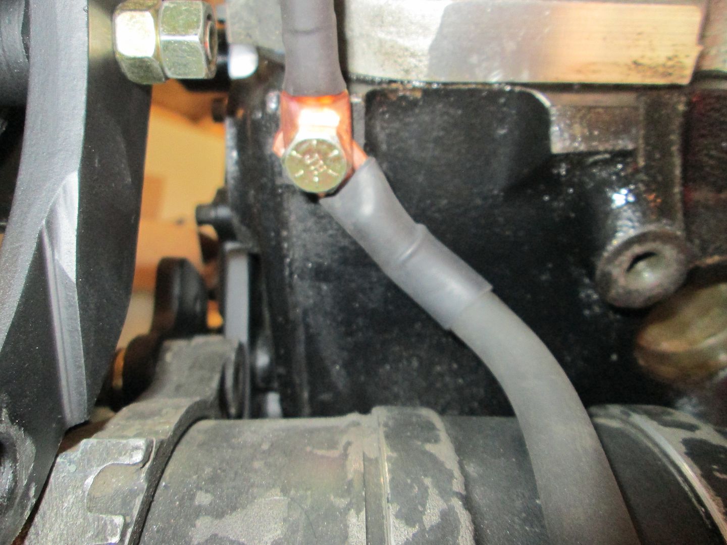
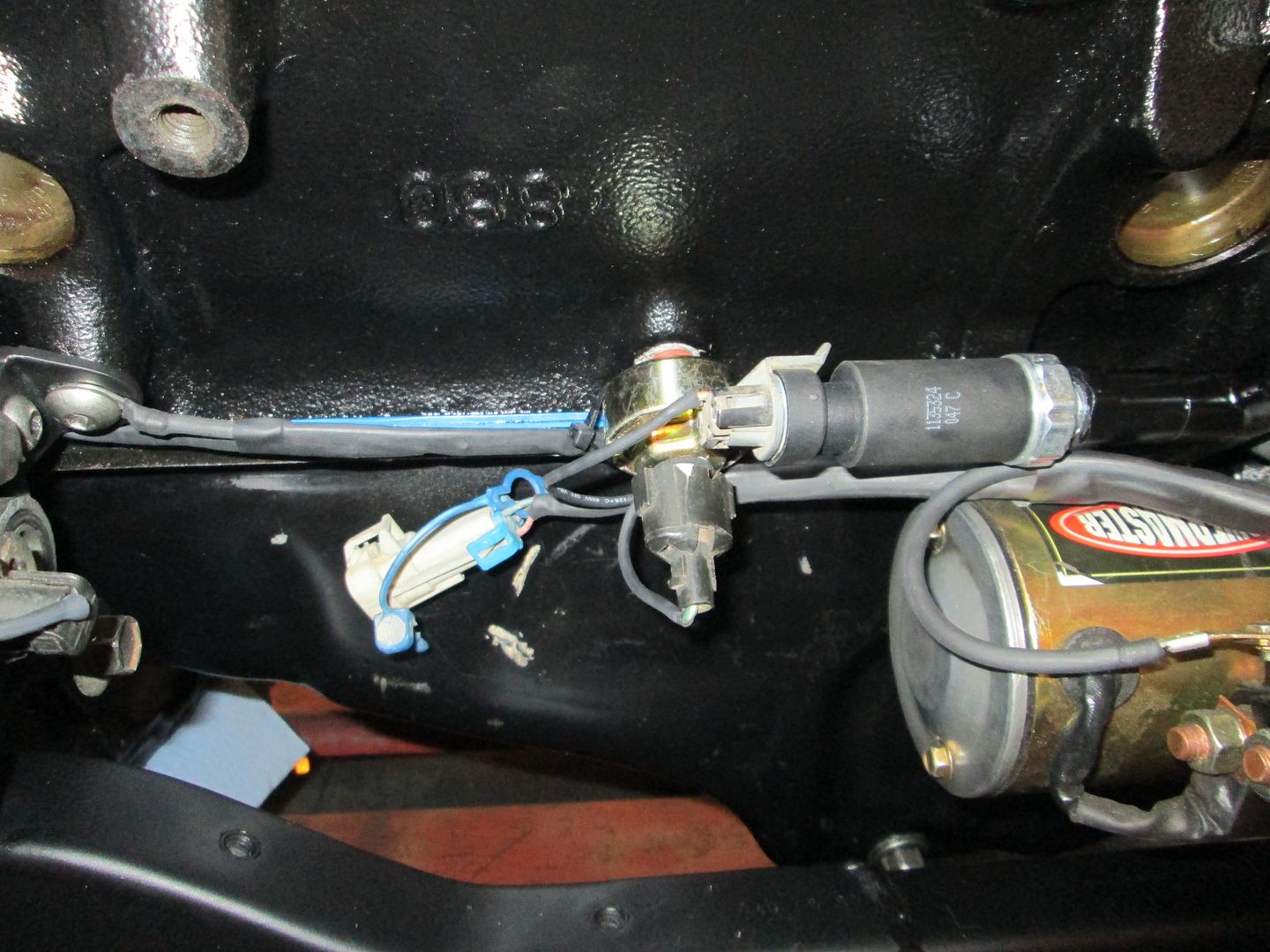
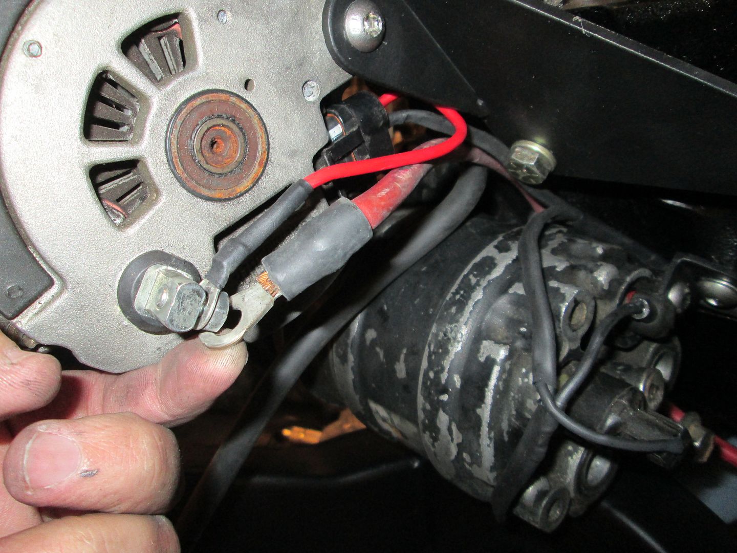
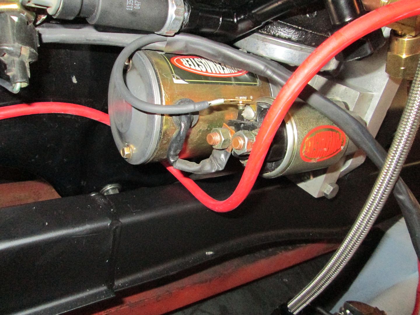
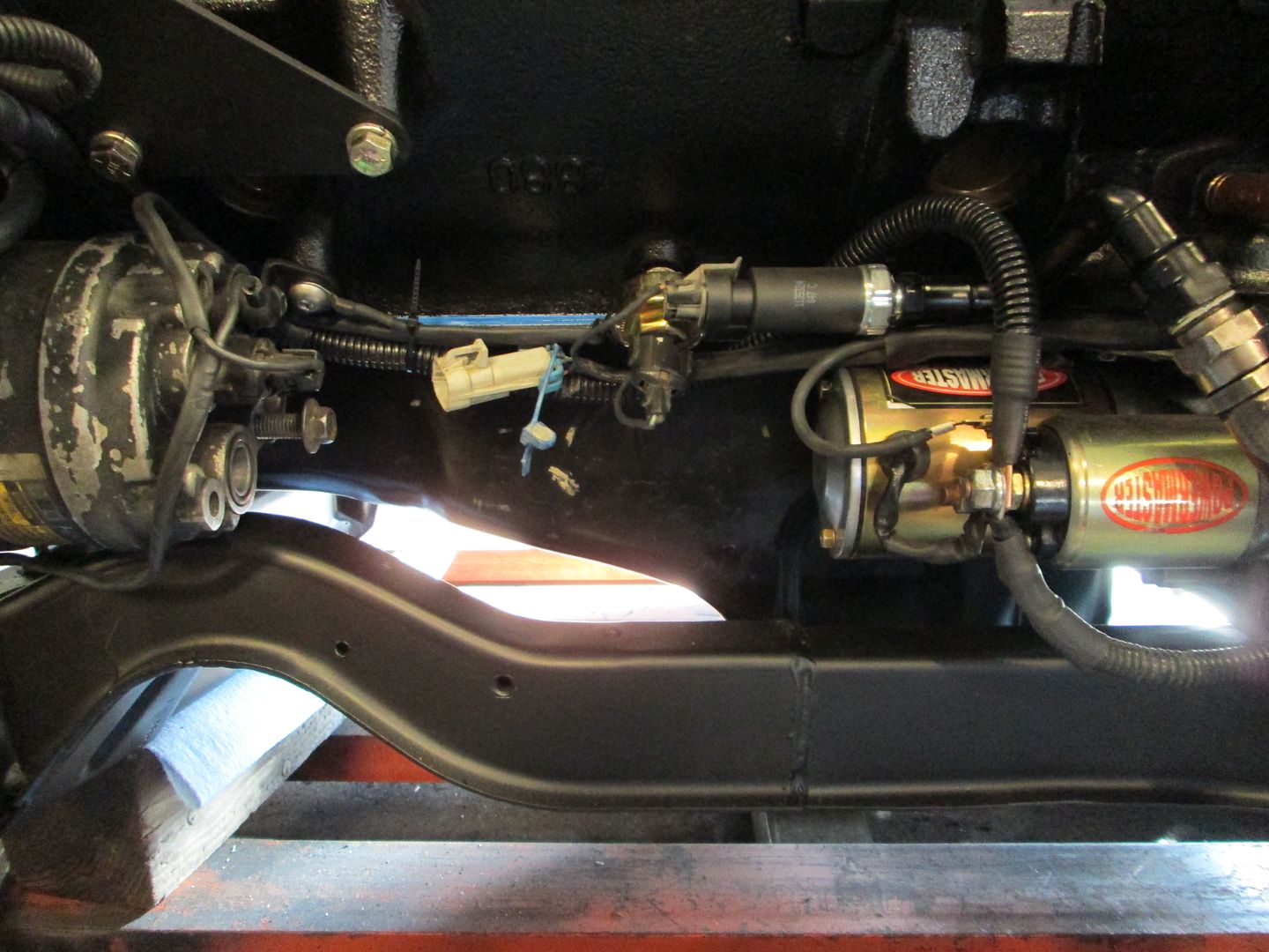
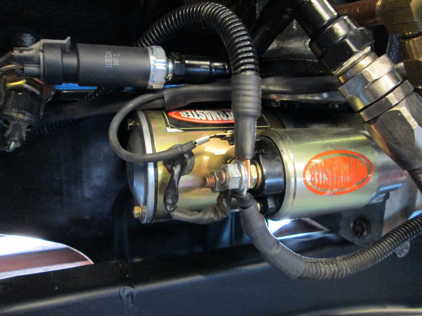
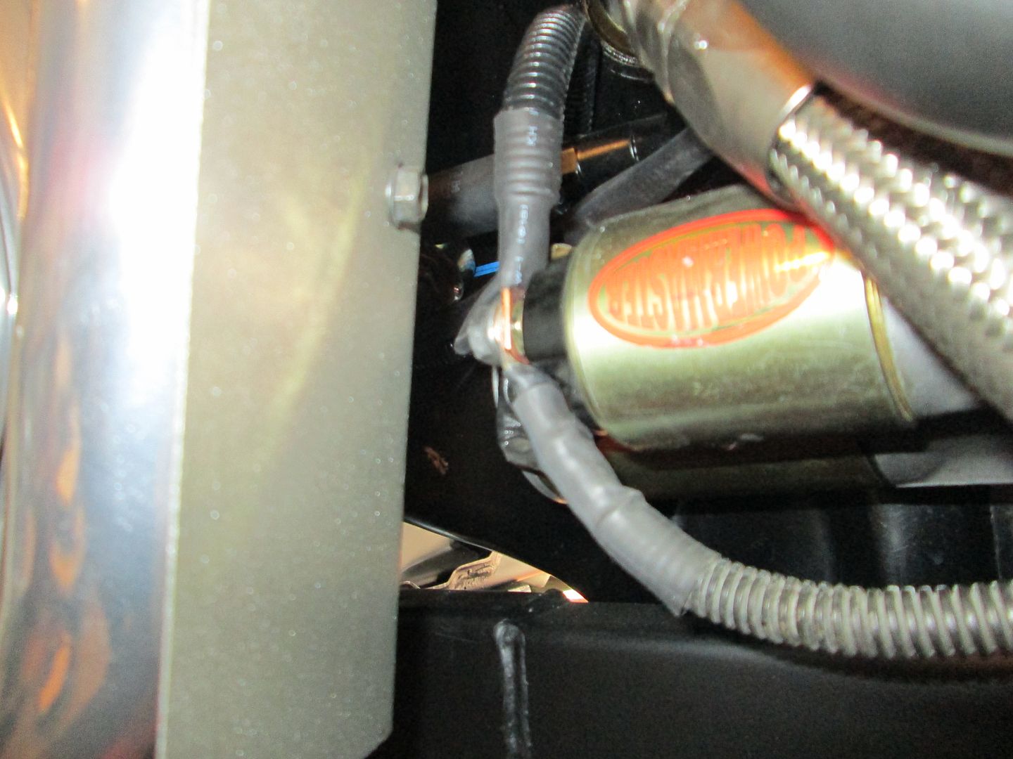
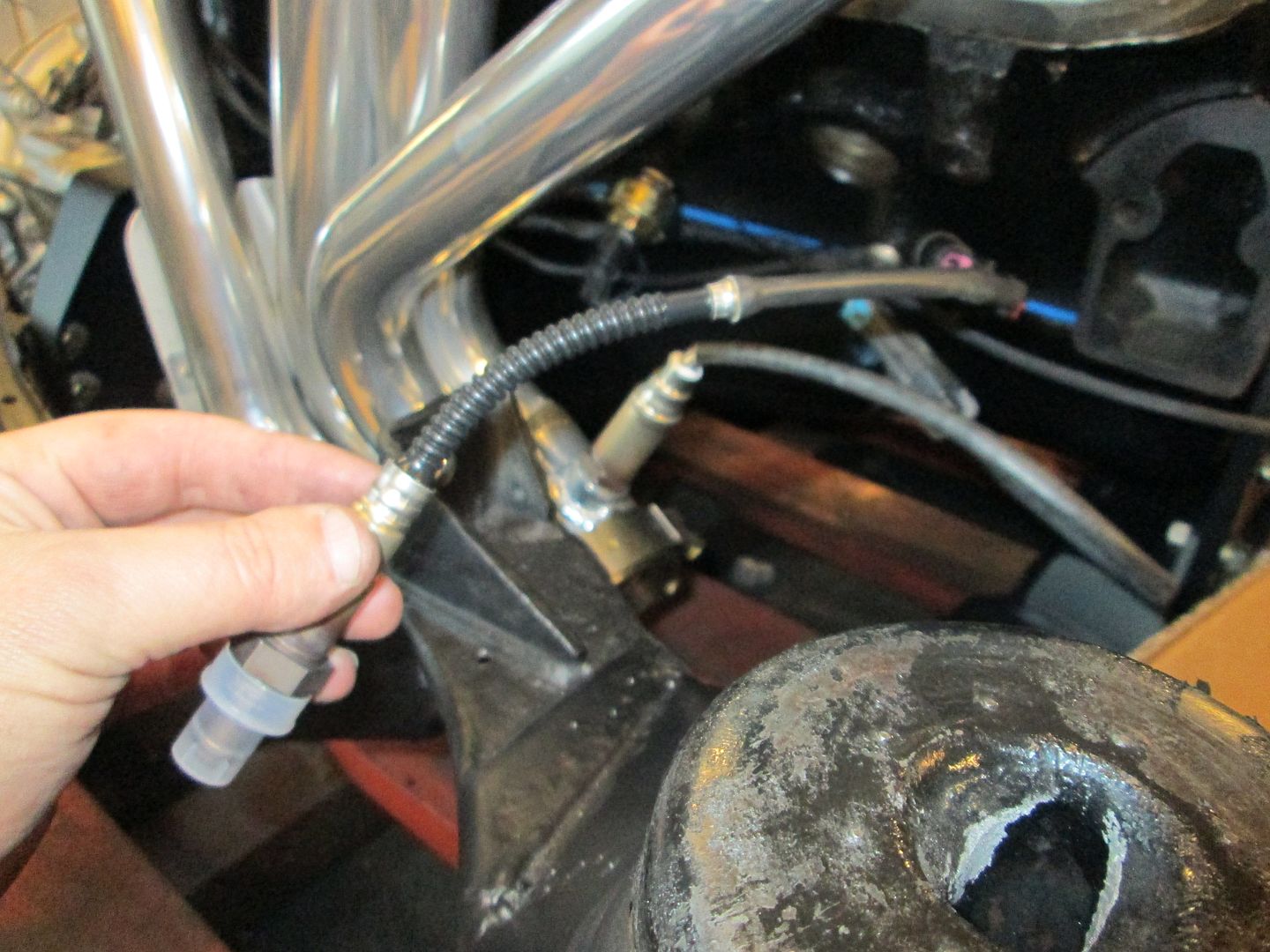
Before I could finish up the header install in the front, I had to finish the power cable from the alternator to the starter:


The cable coming off the starter and going to the bottom goes to the +12 junction by the 500 connector, but all the 500 terminations and this +12 junction will happen in the center console area. There will be 1 more cable connected to the starter - the +12 battery cable from the front of the car.


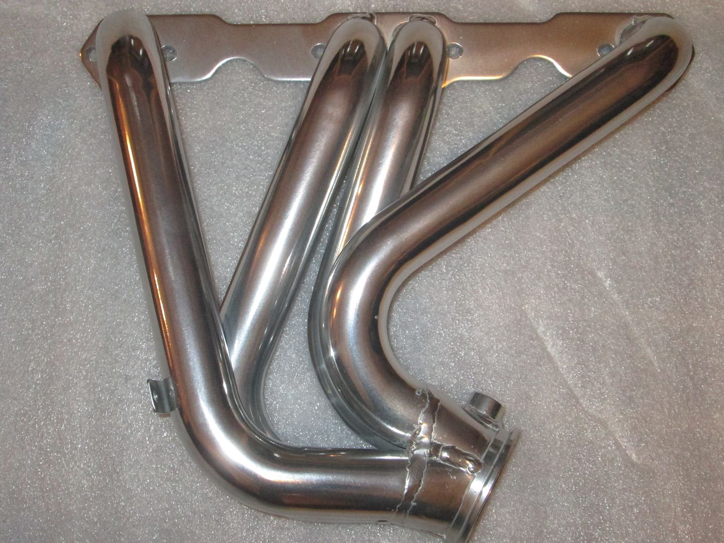
Front header, heat shield, O2 sensor and V-band clamp installed:


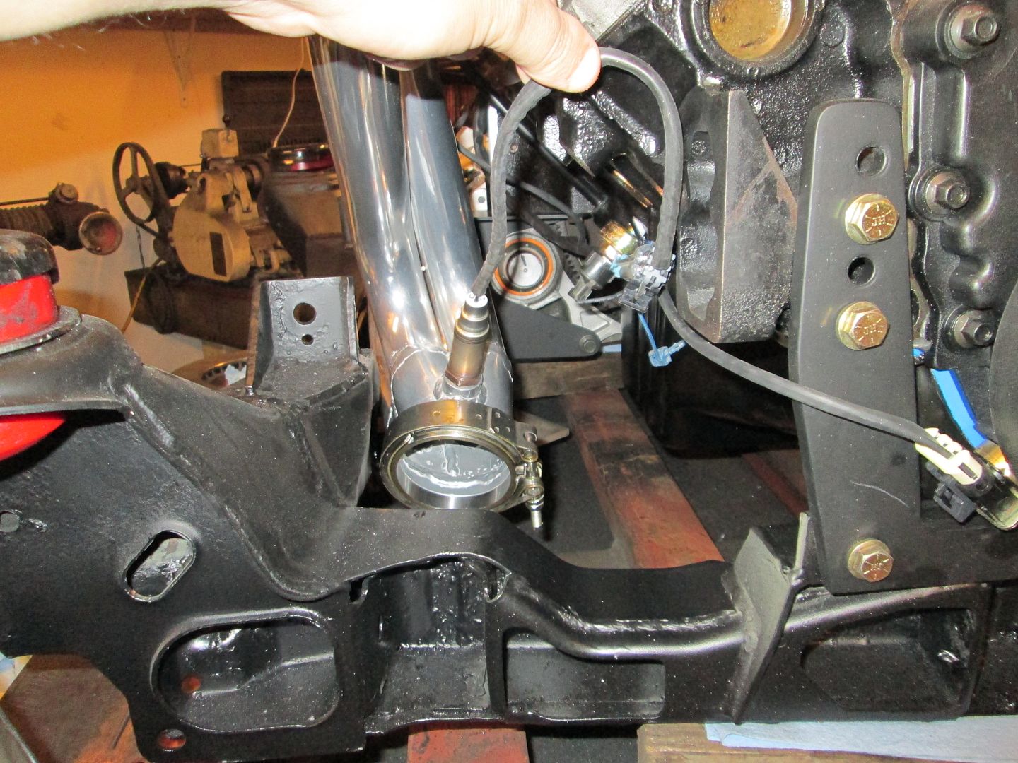
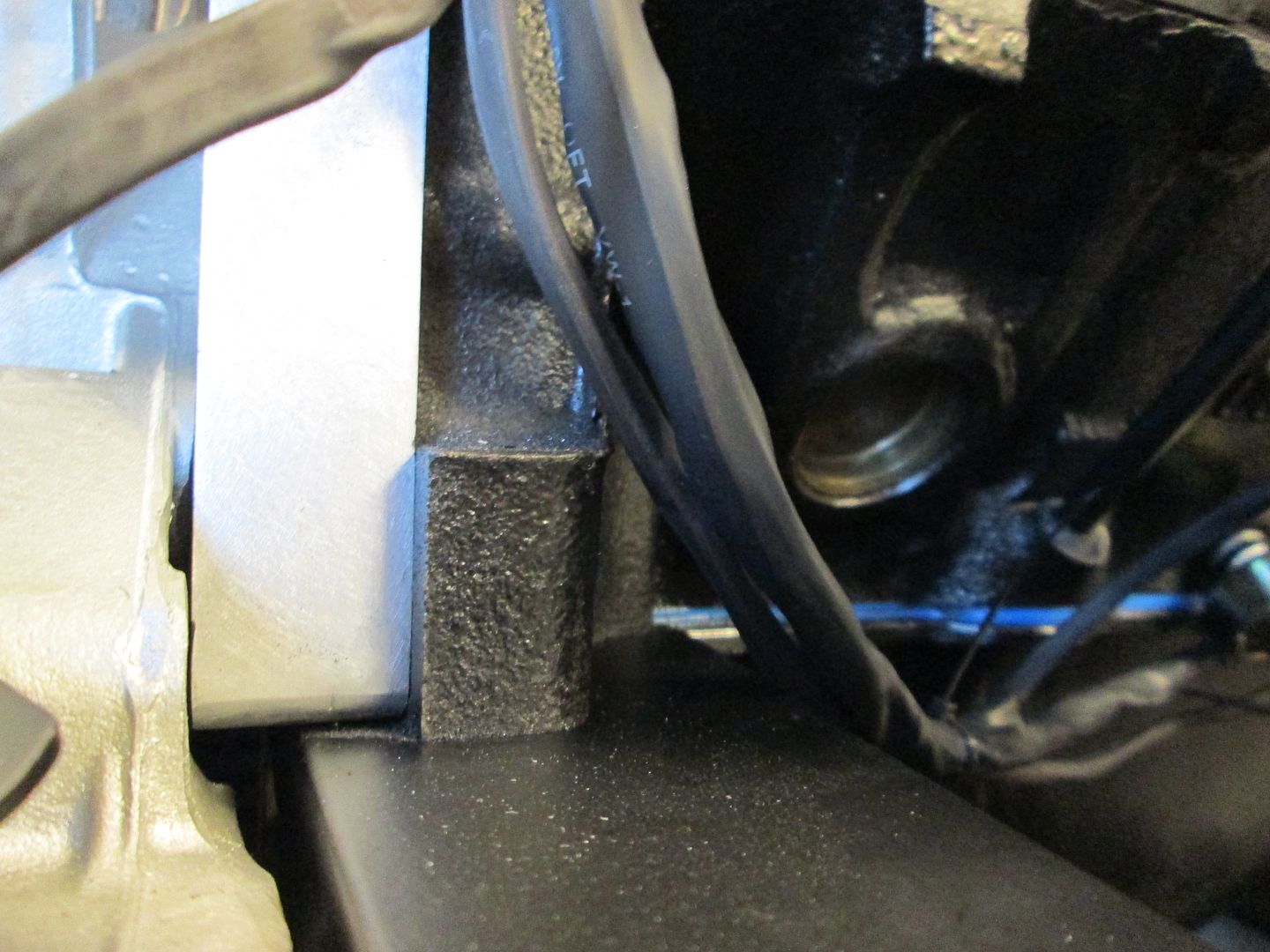
Here is the gap between the heat shield and the starter terminal:


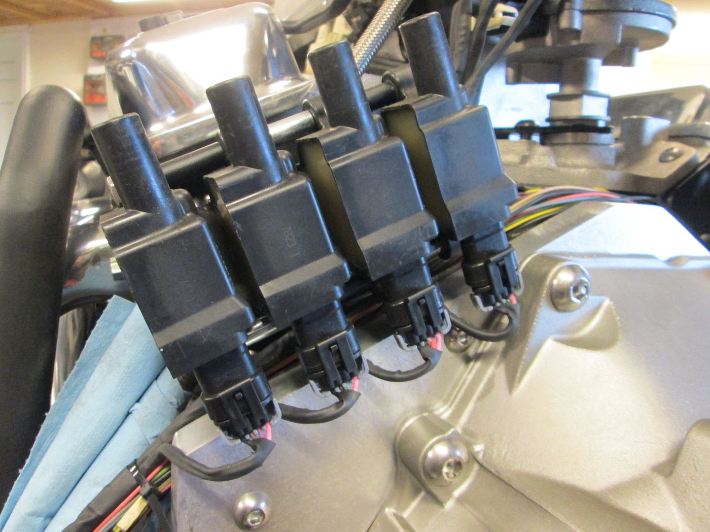
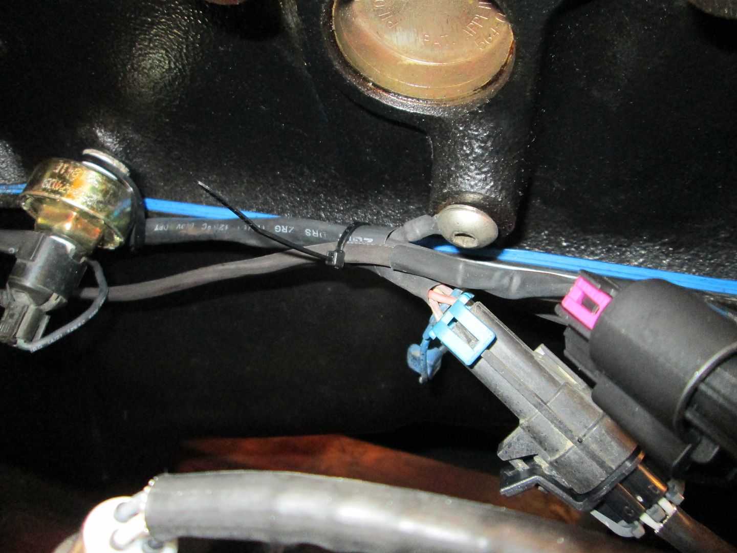
Then I went back to wiring. Bank 1 coils are loomed up and ready for terminating at the other ends.


I started on Bank 2, but it isn't ready for pictures yet.

IP: Logged
Trinten
Member
Posts: 1352
From: Mebane, N.C.
Registered: Sep 2008


Feedback score:    (8)
Leave feedback

Rate this member

Report this Post01-01-2014 06:39 PM Click Here to See the Profile for TrintenSend a Private Message to TrintenEdit/Delete MessageReply w/QuoteDirect Link to This Post
Oh wow! Even with the o2 sensors that close to the exhaust, they still needed to be the heated style? Damn, I didn't realize their required operating temps were that high! I would have bought the wrong ones... probably caused a bunch of issues when trying to get it tuned.

And this, everyone, is one of the many reasons why I ask people who know waaay more than I do to work on this thing. lol

Looking incredibly awesome...
IP: Logged
fieroguru
Member
Posts: 12128
From: Champaign, IL
Registered: Aug 2003


Feedback score:    (45)
Leave feedback


Total ratings: 258
Rate this member

Report this Post01-04-2014 06:15 PM Click Here to See the Profile for fieroguruSend a Private Message to fieroguruEdit/Delete MessageReply w/QuoteDirect Link to This Post
With OBD2 the O2 sensors are heated to make their readings more consistent. I use them on pretty much every swap these days.

Back to the wiring...

Bank 2 coils are wired up:


Coil sub harness joining the main harness:


Top side sub harness joining the main harness:


Here you can see the front sub harness join the main harness and then the wires split with one set going to the ECM area and the others pull aside to go inside the passenger area:


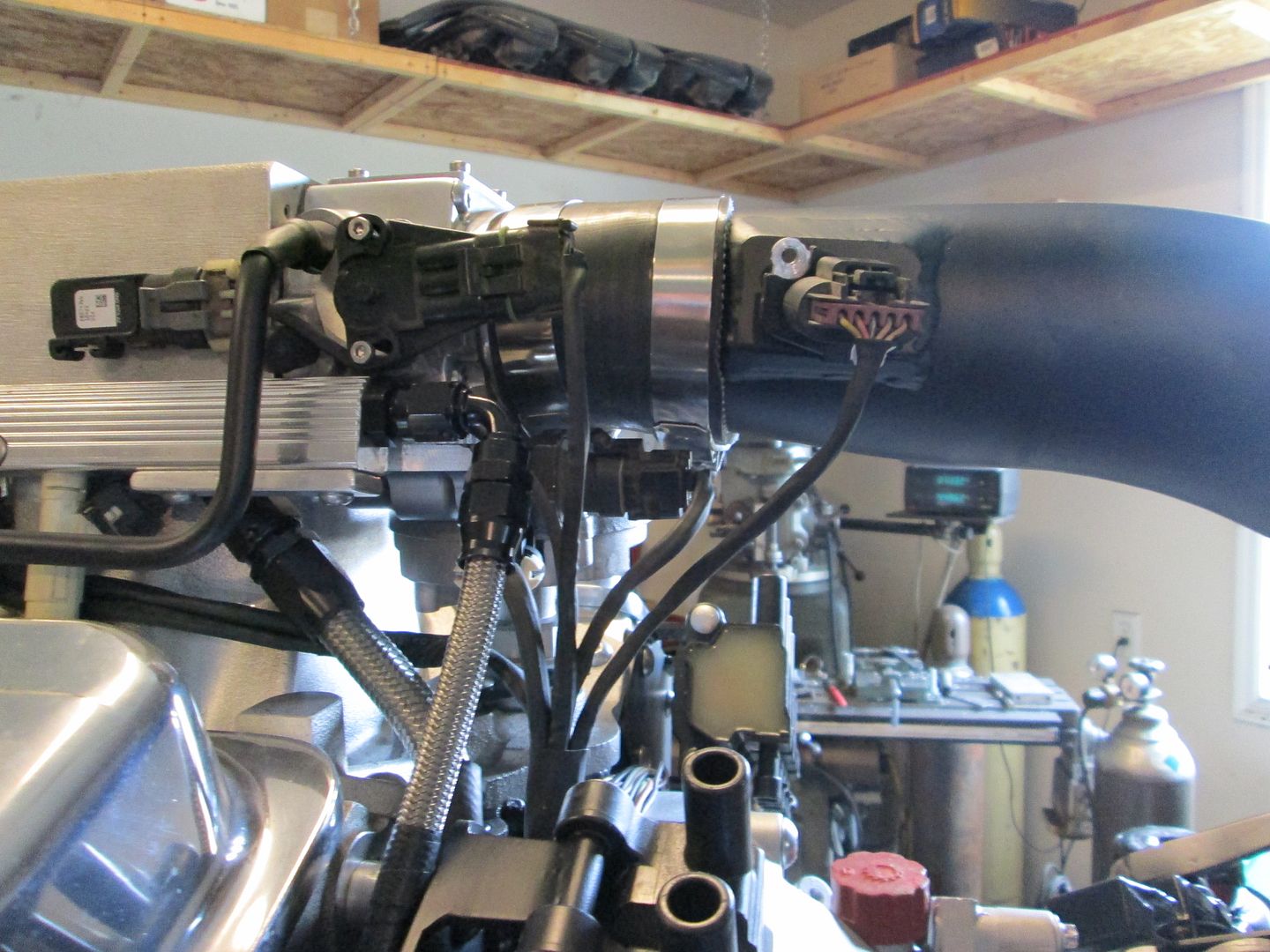
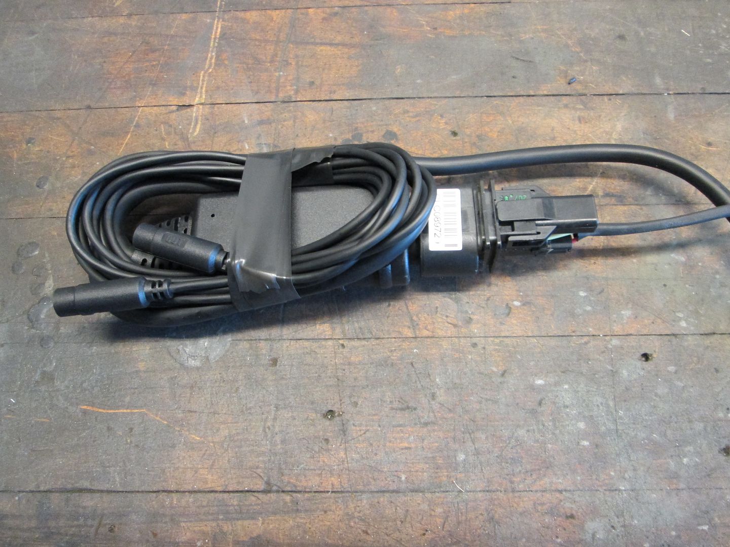
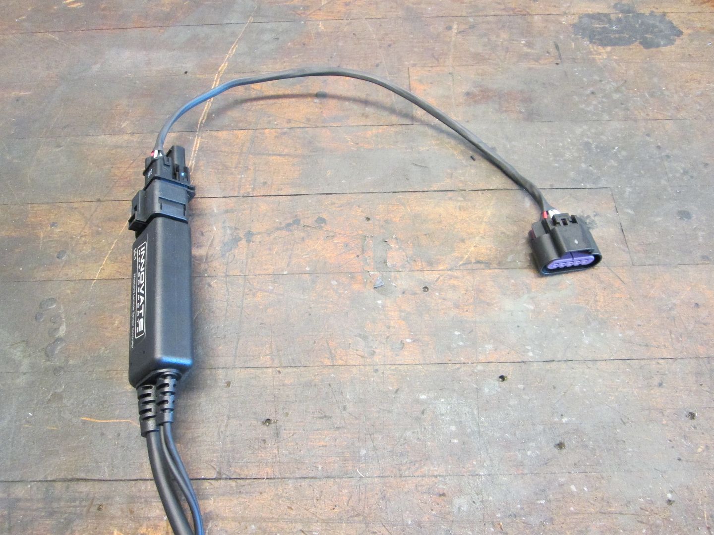
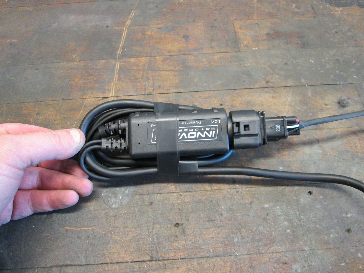
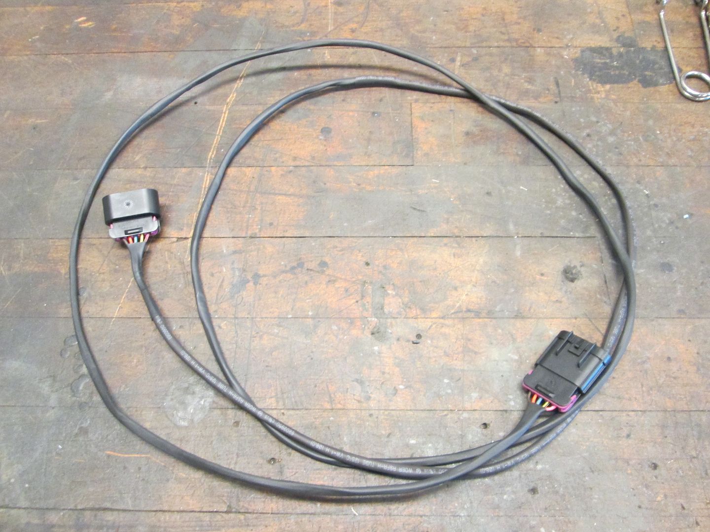
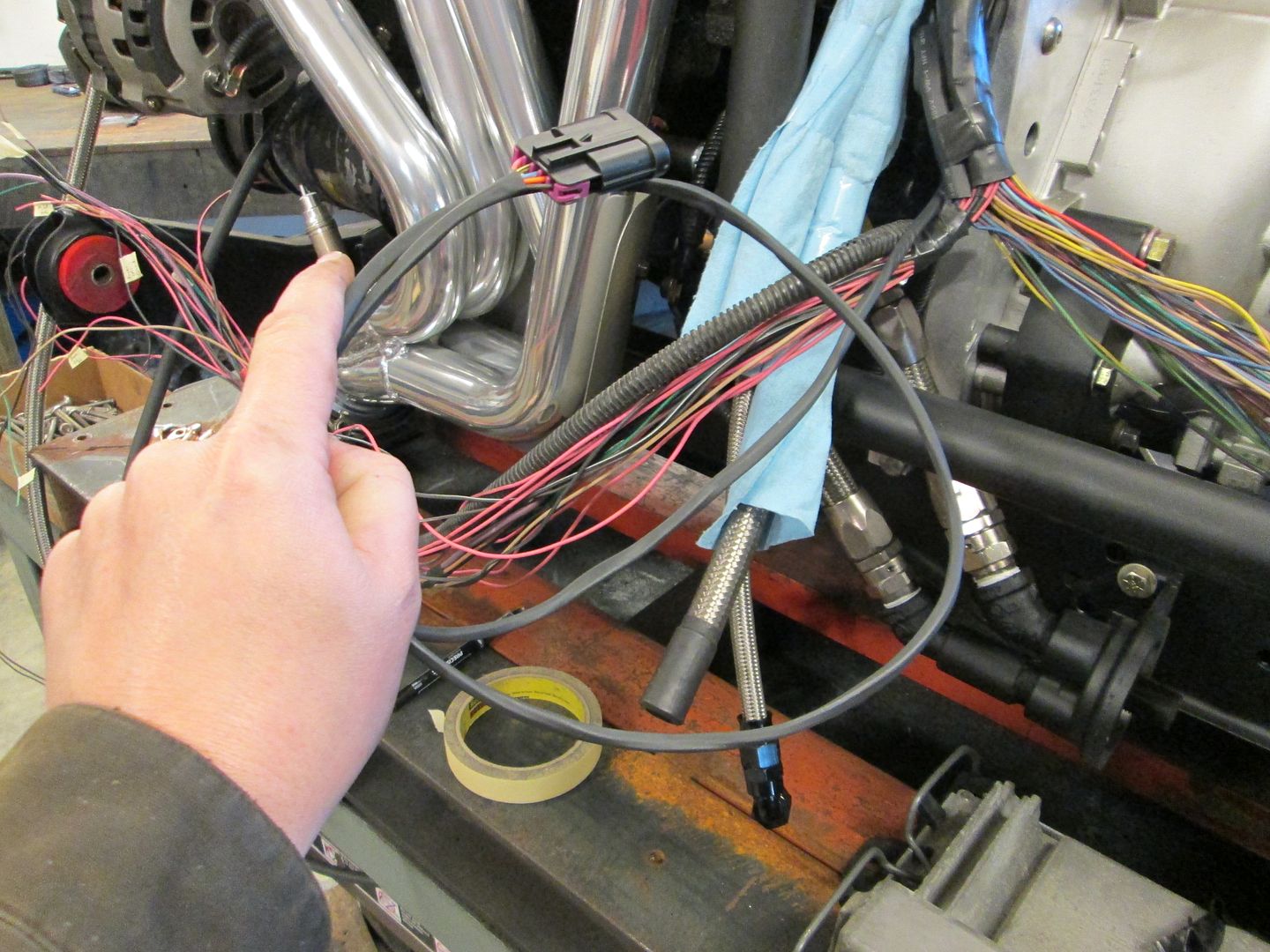
Then I started working on the wideband... more wiring. The wire length from the wideband O2 sensor to the controller is quite short and would require the controlled to be in the engine bay along the engine. The controller has 2 cables that are not needed, so they have to be coiled up and the other cable with the connection wires is too long... so I coil things up like this:


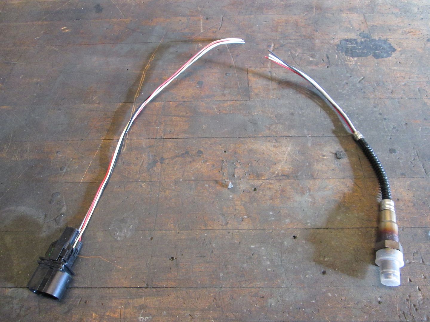
Now to put the controller inside, I have to extend the O2 sensor wires, so start with a simple cut:


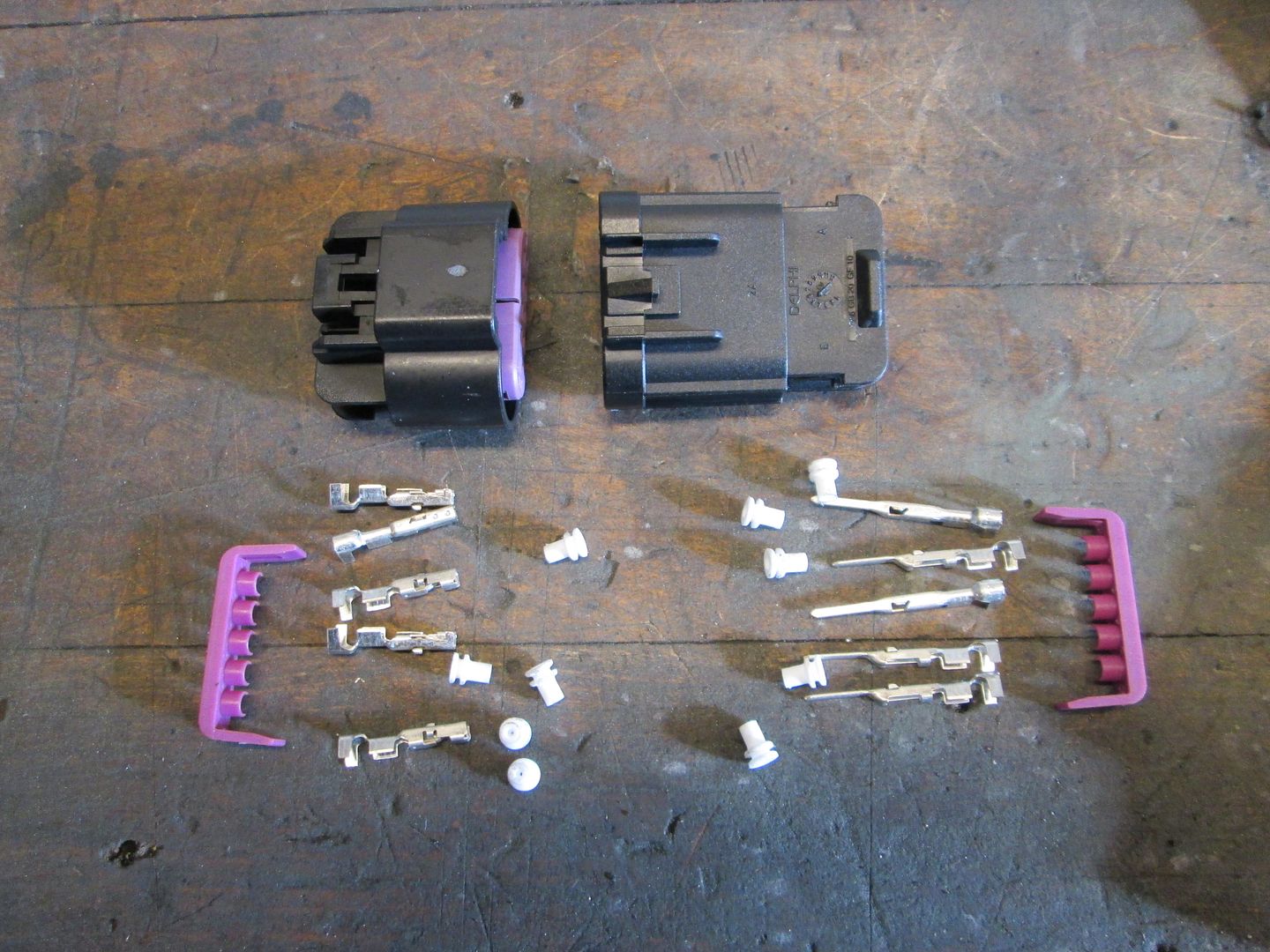
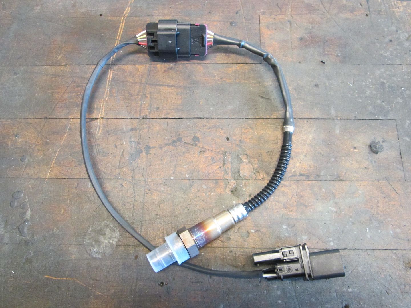
Use some matching male/female connector ends to repair the cut:


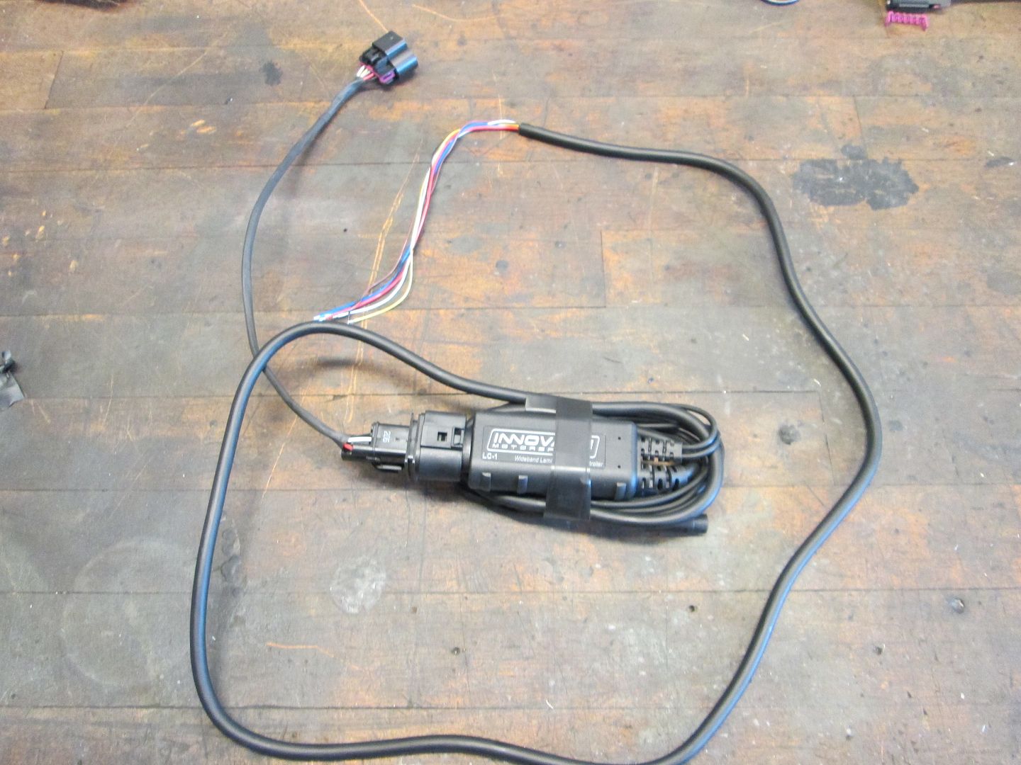
Here is the controller with the new connector end and the approximate location it will be located. The O2 harness runs on the stationary side of the shifter, the other cable will be wire tied to the vacuum tube to keep it away from the shifter:


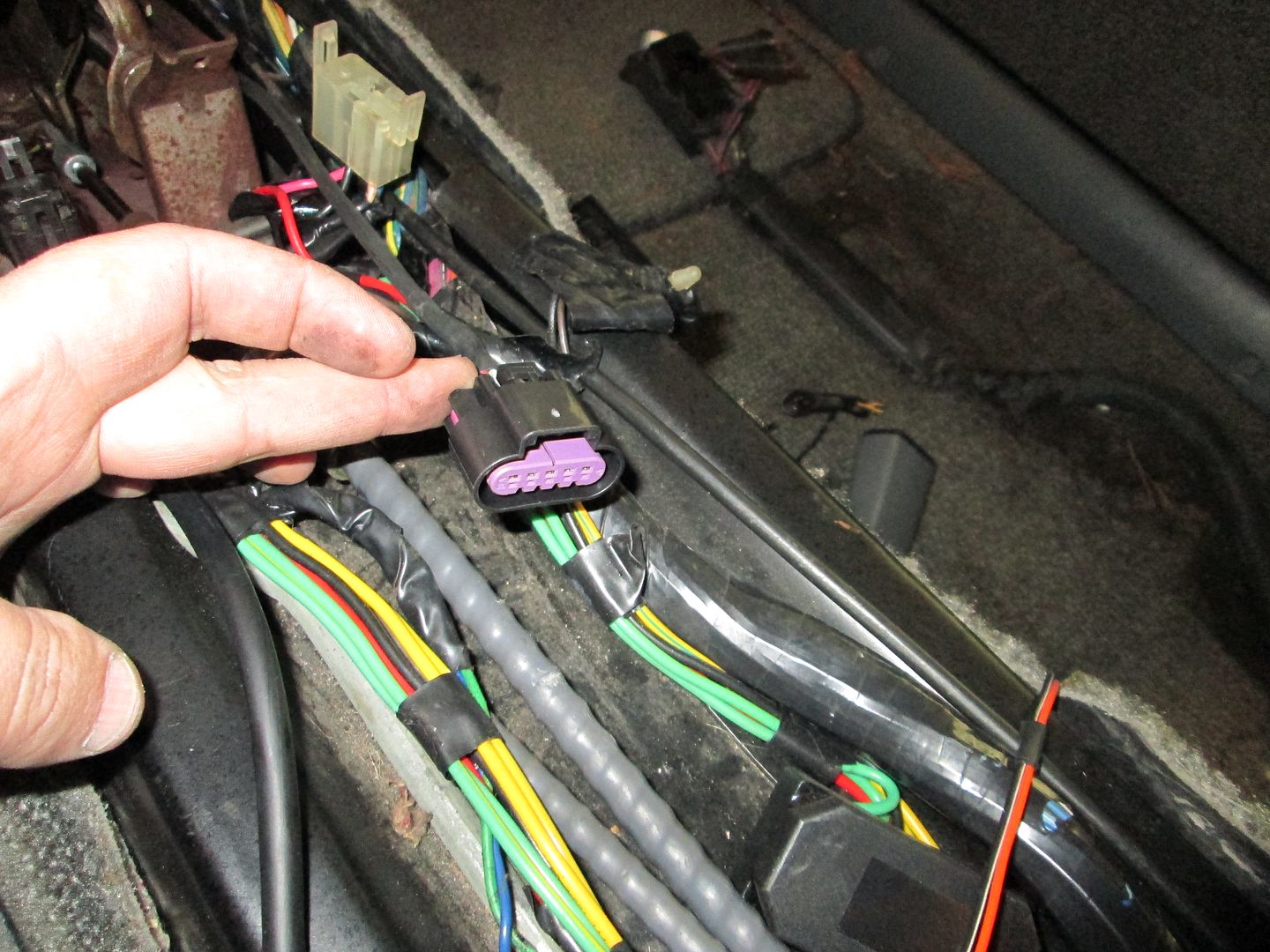
While in the car, I measured the distance from the connector to the firewall so I can make the jumper section of wire using the same connector ends:


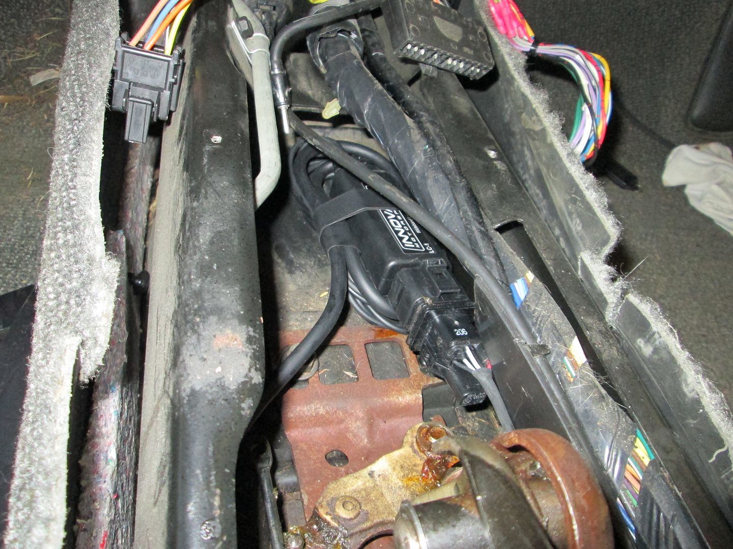
Here is an approximate location for the wideband O2 sensor:


Then I wire tied the wideband sub harness to the engine harness:


Here is the other end ready to go into the car:


On Sunday I am going to take a short break from wiring and fab up the ecm bracket. Once that's done, I can start terminating the wires at the ecm.
IP: Logged
fieroguru
Member
Posts: 12128
From: Champaign, IL
Registered: Aug 2003


Feedback score:    (45)
Leave feedback


Total ratings: 258
Rate this member

Report this Post01-10-2014 07:26 PM Click Here to See the Profile for fieroguruSend a Private Message to fieroguruEdit/Delete MessageReply w/QuoteDirect Link to This Post
I am glad the single digit temps have left KY!

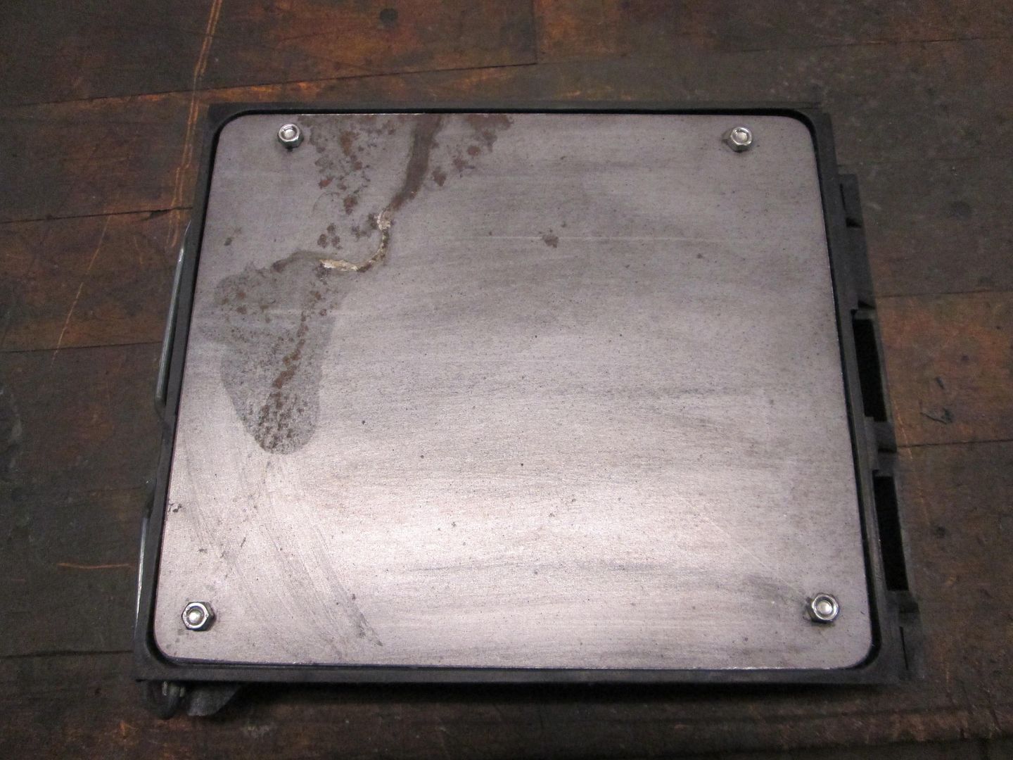
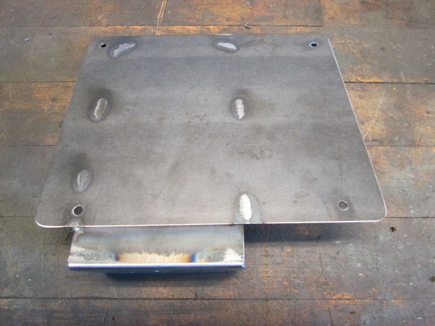
Started on the ECM bracket. Cut all the plastic tabs off the ecm holder, cut out a piece of 16ga to bolt to the back, marked the holes, countersunk the ones on the holder side (so they can't touch the ecm and ground the case), and then bolted it together:


IP: Logged
fieroguru
Member
Posts: 12128
From: Champaign, IL
Registered: Aug 2003


Feedback score:    (45)
Leave feedback


Total ratings: 258
Rate this member

Report this Post01-11-2014 01:21 PM Click Here to See the Profile for fieroguruSend a Private Message to fieroguruEdit/Delete MessageReply w/QuoteDirect Link to This Post
The ECM mount is now done, I will paint it once the wiring terminations at the ecm are done.

Fabbed up this bracket to bolt to the cradle and weld to the back plate on the ecm holder:


IP: Logged
fieroguru
Member
Posts: 12128
From: Champaign, IL
Registered: Aug 2003


Feedback score:    (45)
Leave feedback


Total ratings: 258
Rate this member

Report this Post01-11-2014 08:18 PM Click Here to See the Profile for fieroguruSend a Private Message to fieroguruEdit/Delete MessageReply w/QuoteDirect Link to This Post

fieroguru

12128 posts
Member since Aug 2003
All wires have been terminated at ecm:


IP: Logged
Trinten
Member
Posts: 1352
From: Mebane, N.C.
Registered: Sep 2008


Feedback score:    (8)
Leave feedback

Rate this member

Report this Post01-12-2014 10:55 AM Click Here to See the Profile for TrintenSend a Private Message to TrintenEdit/Delete MessageReply w/QuoteDirect Link to This Post
Nice!

I saw some papers floating around there with some highlighting - was tracing things to rewire a tremendous hassle? I think I had seen all the tracing/crossing work you had to do on your swap, so I was just hoping this was not that intense.

Thank you for the great tutorial. I really like the solution came up with for the ECM!
IP: Logged
Previous Page | Next Page

This topic is 18 pages long:  1   2   3   4   5   6   7   8   9   10   11   12   13   14   15   16   17   18 
next newest topic | next oldest topic

All times are ET (US)

Post New Topic  Post A Reply
Hop to:

Contact Us | Back To Main Page

Advertizing on PFF | Fiero Parts Vendors
PFF Merchandise | Fiero Gallery | Ogre's Cave
Real-Time Chat | Fiero Related Auctions on eBay


Copyright (c) 1999, C. Pennock