I see I found this thread a few years ago and commented. I had completely forgotten about it. Thank you for reminding me. I will reach out to these guys as well.
The AFCO radiator I am using is 2 rows of 1" tubes, cross flow setup.
I have a 180 degree thermostat and the highest engine temp I saw last summer was 190 in stop and go traffic with the AC on. I have the factory radiator fan and shroud, so far so good.
I talked with them today, it was a good conversation. Calling the number you had put in your post originally the gentleman there gave me the number to US Radiators parent company down the street, CGJ.
I called there, spoke with a pleasant woman named Tina. I told her what I had and the target power, she said it would likely need to be a completely custom setup. She said they could try building their standard depth radiator (3.25") using 1.5" tubes, and they could fit 7 of those in that setup. She also said they have a 5" deep unit that has 11 tubes, but also has larger tanks.
She asked for some numbers off of the stock Fiero core, and the math ran into some issues with the size of the tanks they use in both cases.
Because of this, she asked for me to do a little sketch and some dimensions and notes - I told her it would be amateur hour, and she laughed, saying they've seen things literally drawn on napkins. As long as their engineers can read my writing, they can use it to make a proper tech drawing and send it to me for review.
She did say that the rough estimate for the 3.25" deep radiator with those 1.5" tubes would be around $1000. The larger one wouldn't have a ballpark quote until they have my sketch.
So I'm working on my terribly amateur drawing and going to organize key notes in the margins, scan it and email it off with some pictures and additional commentary. We'll see what they come up with. They also offer fans and shrouds, though the ones they list (Some are by Spal) aren't pushing as much air as the Delta PAG fans.
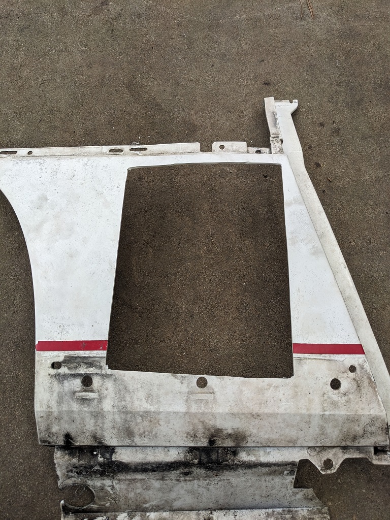
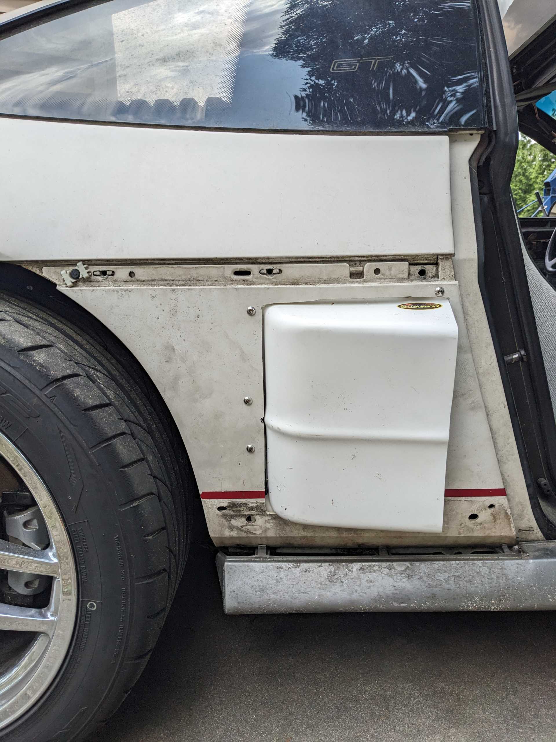
More puttering around today. I measured the lower quarter panel as I had an idea to save Mike a little work, and that was to get some air scoops of some kind. I found some that are 11x7x3.5 (the width of the opening is 11). They have a nice lip for riveting into place. It'll be a quick addition. We discussed doing it on both sides, and getting the biggest fluid cooler we could to fit into that new space, using the pinch-weld on the bulkhead curve of the back of the cabin as the intended mounting point.
The one I found that looks good (and has the appropriate -6 AN connectors on it already) is 11x6 and will fit in there okay. It's only 0.75" thick. I asked Mike if he wanted me to find a bigger one, and we'd have to do a reducer for the AN fitting (as the larger ones are using larger AN sizes, or other fittings entirely). He said maybe and to get some options together.
He's okay if the cooler is partially obstructed by the frame/bulkhead curve, we're going to try to position it so it extends out and fills in as much of the scoop as possible. On the passenger side will be the unit for the fuel, and on the driver side we're going to put a transmission cooler there, and take the one up front out of the 'stack' of coolers.
He said I shouldn't need to worry about getting ones with fans, since we'll have good air flow except when sitting still.
I might order the scoops now (and maybe sacrificial quarter panels from the Fiero Store), but I'll hold off on the coolers until he's done with his buddies Grand National and is able to work on my car again. I have a suspicion plans might change a little again after we get the scoop setups done. We'll see!
On the radiator side, Delta PAG is backordered on their NPT temp sender. They have a 'probe' option that would stick into the fins by the outlet tube but Mike would rather not use that style.
I need to finish up my terrible drawing and notes to send over to CGJ (US Radiator's parent company) so they can quote me on some options. This might make it work out about the fan. If the unit they make me is an 18" tall core, the 18" fan will be right at the edge of the radiator, which is both good from a coverage aspect, and not good from a mounting and shroud standpoint. So I'll wait to see what CGJ comes up with before I order the fan. They have a 16" one that also moves more CFM than Spal units I've looked at.
I swapped in my instrument cluster today, connecting just the C3 connector. Temp gauge still did nothing. Mike said "We ohm'd out the wire going to the connector." to which I replied "We ohm'd out A wire going to the connector. You had me look it up. I could have looked at the wrong diagram, who knows."
I found an article on FieroFocus on how to fix the "temp gauge needle pegging issue", and that article circled the wire position on the C3 connector for the temp gauge, so next time I'm out there, I"ll see if that's what we hooked it up to. If it is, then we must have a bad sensor. Unless there's something else that would be keeping two different gauges from working.
And I did grab the current transmission and engine tunes, just so I can look at them and try to educate myself some more and ask other people more dumb questions. lol.
I took the other gauge cluster and decided to bench test the temperature gauge.
I had a wire with a resistor in it already. Some alligator clips, paper and plastic and other things to keep things isolated, and started trying to test the gauge. Resistor is in the Negative/ground wire. I am using this diagram
It says I should be using 11 and 13. The temp gauge would not move on that. So I started touching the positive to all the other pins. Temp gauge started reacting when I touched pin 15!! That's supposed to be for illumination. And no, the lights on the cluster did not light up. So, this diagram is incorrect?
I told Mike about it, so I'll bring this cluster out with the test wire I used and show him, then when he has time we'll check that out on the cluster I swapped back into the car.
Sorry for the lack of any major posts. Though I'm sure many of you appreciate not seeing so many walls of text from me.
As Mike is still busy on the Grand National, I've been putzing around with learning FAST's tuning software and playing around with the start-up tune.
Quick note on that, I emailed FAST asking about resources to learn how to tune with their software that offered "at my own pace" learning, versus a real-time class or reading what other people have done to fix specific issues and randomly trying those without knowing exactly how/why it might work. Matt over at FAST was really cool, gave me some resources, asked about what I was dealing with, offered some suggestions and even said I was welcome to shoot him another email if I was still having trouble. How awesome is that?
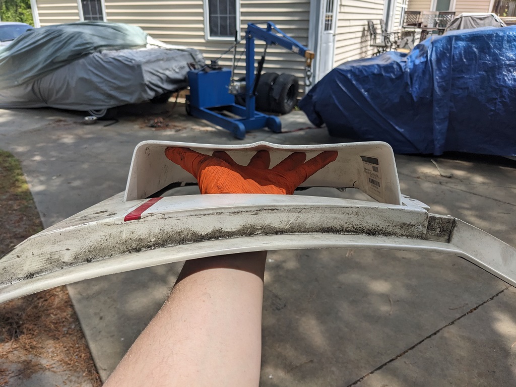
So besides that, I got in my scoops for the rear quarter panels. They are a quality piece, though they are obviously designed to mount on more-flat-than-the-Fiero-quarter-panel surfaces. I didn't see a good way to pie-cut/relief-cut the scoops to make them fit closer to the outside of the panel, so I decided to fit them from the back. That way any remaining gap really won't mean much.
I started by cutting out a piece of cardboard that fit in the open space of the scoop. I intentionally went with a smaller footprint, because you can always make the hole bigger, but tough to make it smaller. I was also using a 4" cutting/grinding disk to do this, so there's a few spots where the cut didn't stay 100% straight. But that's okay. This is also quasi-temporary.
As you can see, the hole is encroaching on where the baseboard trim is, so that sucks a little. It was tough to find a scoop with the exact dimensions I wanted.
Ta-da! Here it after gradually opening up the hole (and trimming the mounting lip of the scoop, you'll see that in a moment.
The joys of power tools that are effective for the task, but not ideal, in the hands of an amateur.
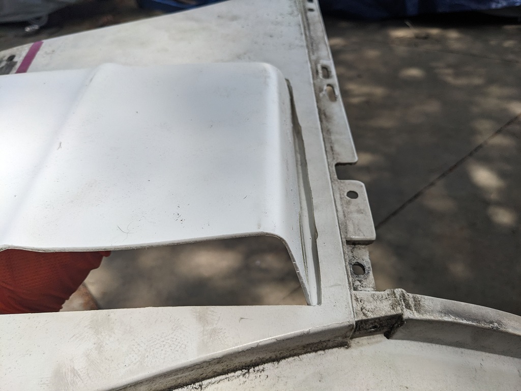
Here's the underside. This is where you can see I was trimming that lip to try to move the scoop as high up as possible, and keep it tucked under the ledge there.
Of course this still leads to the fastening problem. There is still a gap, though now that gap doesn't impact the function of the scoop. I need to figure out what I want to use to affix the scoop to the quarter panel at the points where they meet, so I don't need to flex the quarter panel to mate them together. I thought about industrial strength two sided tape, like what they used to put quarter panel windows on the Fiero? Thoughts?
And for the section(s) that have the gap, do they make a thicker (like neoprene or rubber) material with that same super-sticky stuff? I thought about using the 3M material that holds the lenses on the GT lamp housing, but Mike had some concerns given the potential heat in that area.
Last resort will be to use spacers to keep the gaps as natural as possible, and just bolt it all together with machine screws and metal insert locking nuts (since nylon lockers may melt).
Any other suggestions are always welcome. Once I get this one done, I'll eventually go about doing the same to the other side.
I did also revisit the cooler discussion with Mike, and said I was concerned about the increased air temps from passing through the transmission cooler then going to the intake. He thought about it and conceded it, and was just trying to come up with something that would look uniform on both sides. I said I'd rather it be optimally functional than just uniform looking. So when his attention is back on my car, we'll start workshopping that. Probably start with getting the air intake and filter setup done first, then see what we can build around it.
If we can't package the Vette one I have in there, I did see a late model Mustang stock intake setup on Craigslist that looks pretty compact. And of course there's always going the route of building a box-out for the cone filter and running it down there, similar to how FieroGuru set it up on my last Fiero.
I was able to help Mike out today working on his buddy's Grand National, and we got that running! (and I am a little envious that this stage 2 engine, with a ridiculous turbo on it, 11:1 compression, and aftermarket ECU turned over, fired up, and idled with no tuning/tweaking shenanigans).
When I wasn't needed, I was taking the info I got from Matt at FAST and messing around with the startup tune. While strictly working with what he suggested, I got the cold (okay, semi-cold?) startup tune WAY closer. A few times it started on it's own with a little extended cranking, the other times it would start with me just tapping the gas pedal. No holding it, no easing off, just tap!
The base idle is now up from 950 rpm to 1100 (most of what the info I got was around adjusting the throttle screw, playing with the TPS learn, and watching a value I don't understand outside of "your target here should be between 10 and 20" lol.
I wonder now if the other stuff Mike and I messed with could actually be the issue now. Like there is table about the IAC, and I'm sure that is way off now. But hey, I'm learning!
This past Saturday was cut short, Mike was called into work.
He started to work on wiring up the Fiero oil pressure sender on his 3800 to the Fiero GT cluster to get the oil pressure gauge working, then he'd know how to do it on mine. He had labeled the wires before he did his swap, so the tan wire was already marked as 'oil pressure'. He put the '87 oil pressure sender installed, and when he would go Key-on-engine-off, the oil pressure warning light would come on, and gauge stayed at zero. He'd start the car, and the needle would bury itself, and the idiot light would turn off.
He used his voltmeter to make sure he had it wired right, looking for a change of resistance, and he is fairly sure he wired it up right. I found a few other threads on here with similar issues. One guy installed the '88 oil pressure sender, and it fixed his issue. His car was not an '88. So not sure why that worked, but hey. It's something we can try.
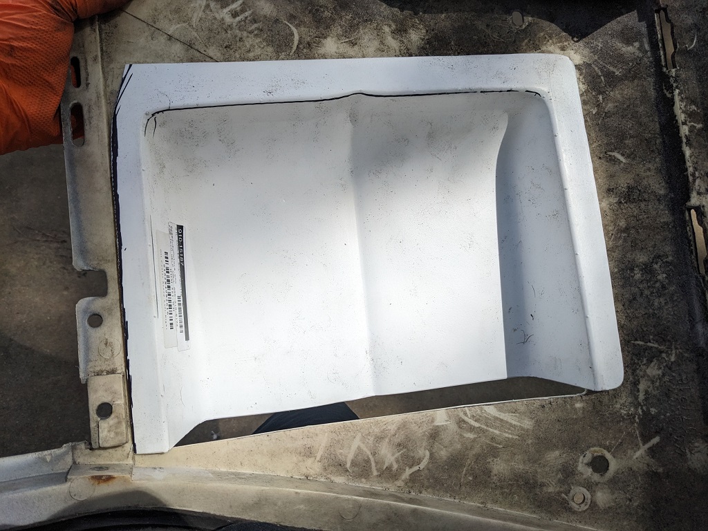
I finished putting the side scoop on the passenger quarter panel. To close the gap I cut strips off of the roll of HDPE (high density polyethylene) I had. Then I used 1/4-20 stainless fasteners with nylon lock nuts. It looks a little odd, but I think it's more because the scoop is all clean and hyper-white, and the quarter-panel.... isn't. lol
I also took more measurements to figure out about how much room we'll have to mount a fuel cooler in there. We'll need to relocate the oil catch can.
I'm looking at the Setrab FP119M22l . It's compact ( roughly 8" x 6" x 4.5" with the bracket), and has a fan that pushes around 350 cfm. I found a vendor that had done their own testing with it. They found that when putting coolant or water through it, temp drops were 15-30 degrees with water, and 100 degrees with oil. They do not say if they mean C or F, assuming F because something that small.
So then I poked around on Summit Racing with my estimated max dimensions (I will make cardboard standins for testing before I buy anything). I found the Derale 65840 . This one is larger, has two fans, and roughly double the CFM. No information on how effective it is. Someone even asked on Summit in the Q&A, no response, which was disappointing as Derale had replied to other questions. I emailed them directly. Their response was:
"Unfortunately, we do not have any data showing how much this cooler would cool fuel or oil."
This seems strange to me. Why would a company make a cooler and not do some testing to advertise it's abilities!? Especially when some of these compact coolers (with fans) can get way north of 500 bucks. The Derale is $890.32! Spending almost a thousand dollars with no idea how effective it's going to be, with no reasonable way to return it if it performs like garbage seems insane.
I reached out to Earl's performance on one of their units with the same question, no reply at all yet.
So I'll mock up some boxes to do test fitments, and see just how crazy I want to get with this. Mike wants to make sure it's shrouded so air can't easily go around it, fan or no.
I'm still waiting on my Radiator fan. They said it would be 4-6 weeks. We are in week 8. I emailed them on Friday. No reply to that, but received an update on my order page that a UPS label was created as of Saturday. Today is Wednesday.... UPS still has not received the package. If that doesn't change by this Friday, I'll call them to see what's going on.
It sounds like your oil pressure sender is bad. If you simply ground that single wire (with the key on), the oil pressure gauge should read 0 and the warning light will be on. With the wire not connected to anything, the pressure gauge should be pegged to the right--which is what it sounds like is happening when you actually have pressure present with your current sender.
That will test to make sure your gauge is functional. Then replace the sender.
[This message has been edited by I Lean (edited 06-04-2025).]
It sounds like your oil pressure sender is bad. If you simply ground that single wire (with the key on), the oil pressure gauge should read 0 and the warning light will be on. With the wire not connected to anything, the pressure gauge should be pegged to the right--which is what it sounds like is happening when you actually have pressure present with your current sender.
That will test to make sure your gauge is functional. Then replace the sender.
I think I either typed something incorrect in my post, or maybe in a bad way to convey the right information. That is what happens. Key on, engine off, the warning light is on, needle at 0. Engine starts, the needle buries itself (and the light shuts off, of course).
I appreciate you reading and commenting, just the same. If I'm still not getting what you're saying, please let me know. Thanks!
That is what I understand is happening. What I'm suggesting to do, is to test the gauge by taking the sender out of the equation, and just ground the wire to the block.
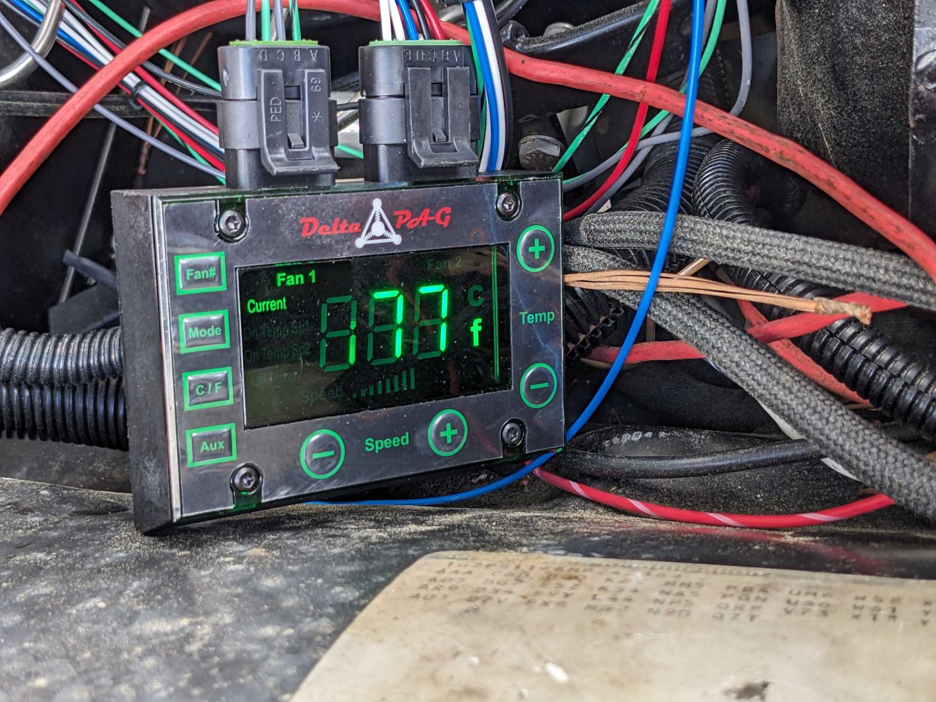
My Delta PAG 18" fan arrived. It's very nice. They did a great job with labeling and wire organization.
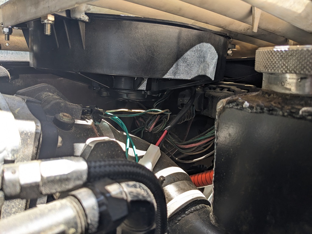
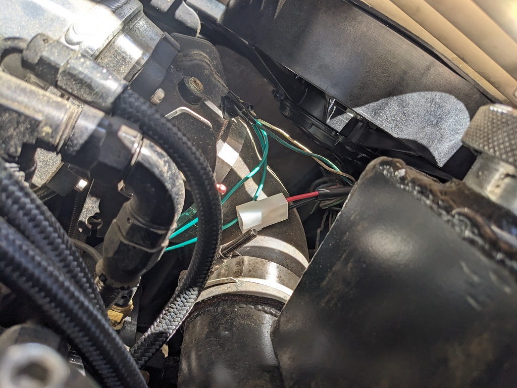
Mike took a piece of aluminum tube to replace part of the radiator hose going to the intake, so we could plumb in the sensor for the fans controller. This also gave us a great chance to look at temp differences and the odd behavior we saw with temps dropping rapidly just by going to Key on, Engine Off.
Good news, my messing with the tune and throttle adjustment screw is paying off, car is starting much easier now! When it warms up it's sitting around 1100-1200, a little high, but I'll take it for now.
Sadly, even with this fan, the temps gradually climbed, just from the car sitting at idle. It took a solid 20 minutes in 85 degree (Fahrenheit) temps to crawl up to 220, when I shut it down.
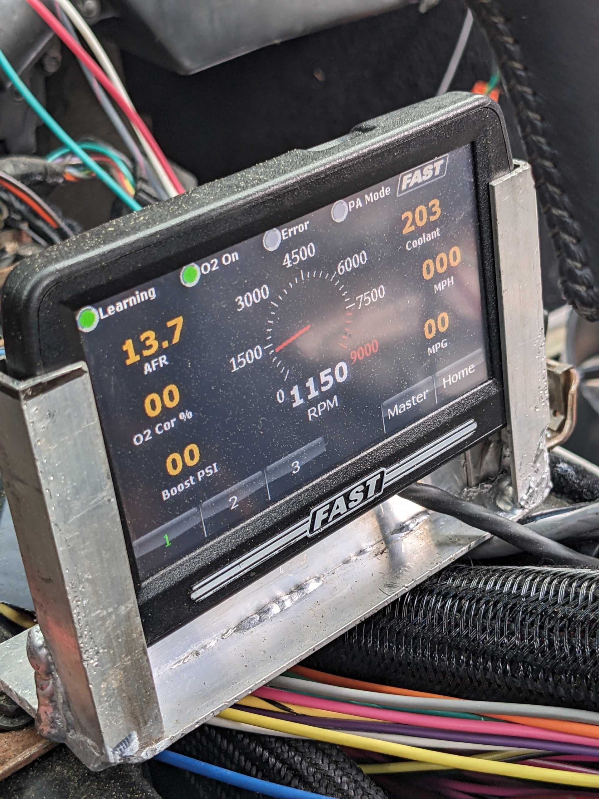
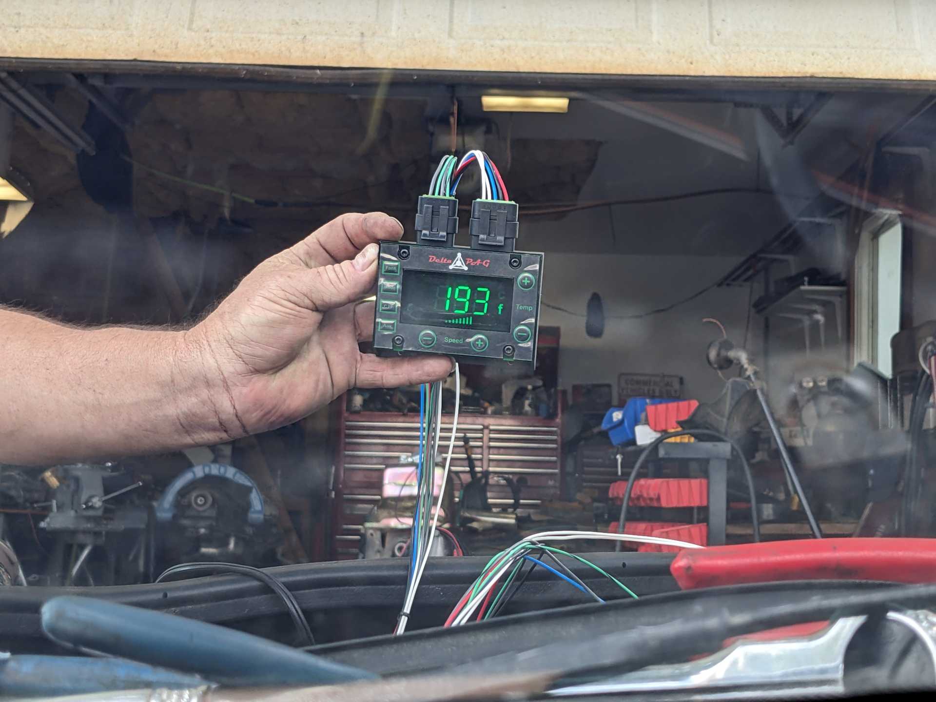
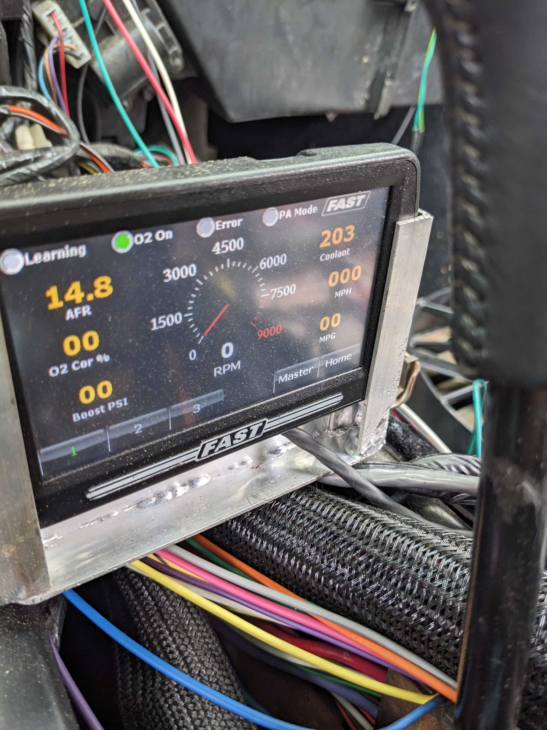
When we first started it up, the delta between the water temp sensor in the intake (stock LS4 sensor) and the fan's sensor in the radiator was about 4 degrees. Makes sense with the metal tube running under the car. As the engine temp climbed, the delta grew. Here's some pictures, grouped together. What the FAST saw first, then what the fan probe saw.
So you can see the FAST was seeing 203 at this point, but the fan probe only saw 177. A 16 degree difference seems pretty crazy.
Then:
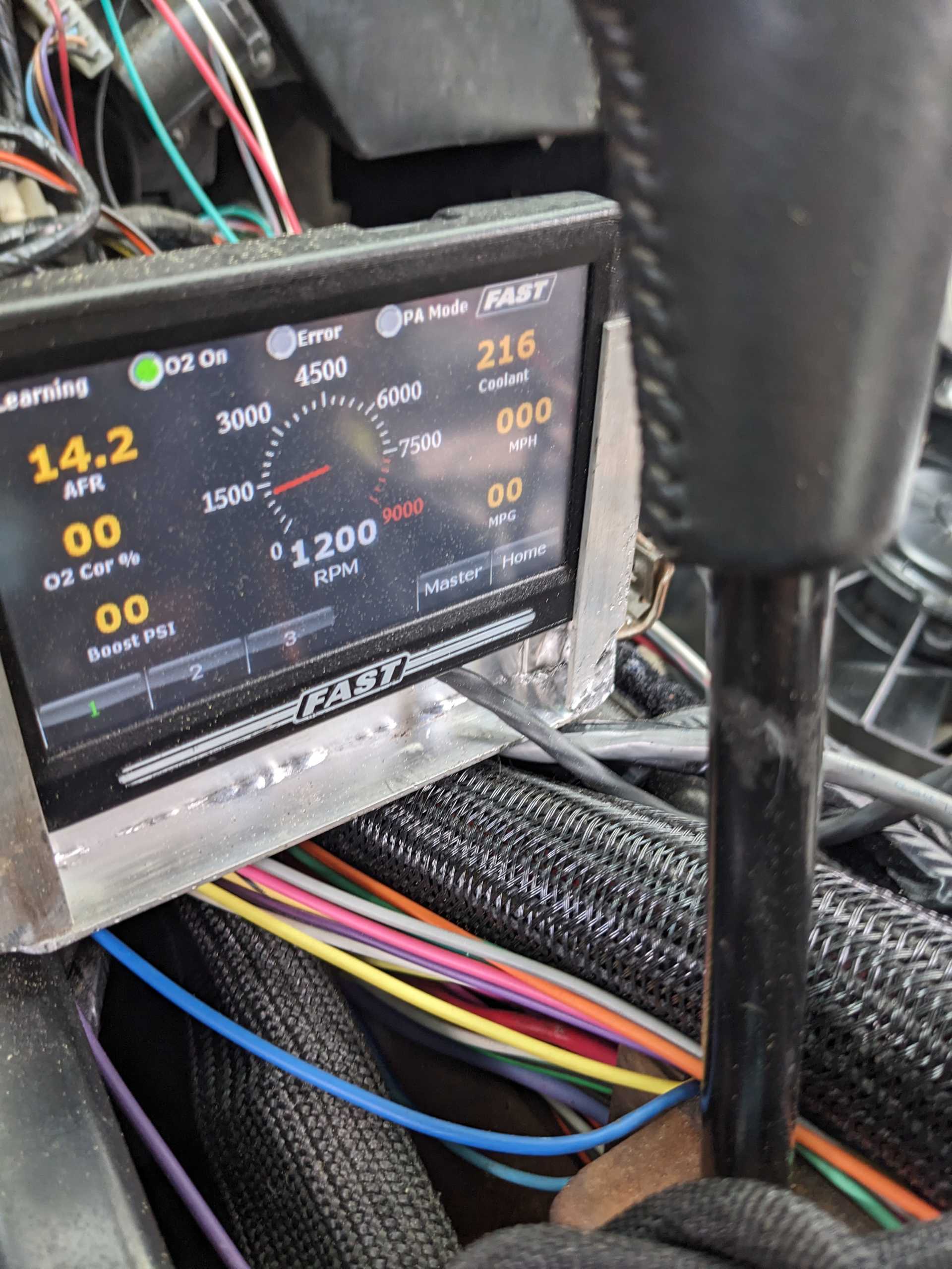
While the FAST was seeing a temp of 216, the fan probe was seeing 193. The delta grew from 16 to 23.
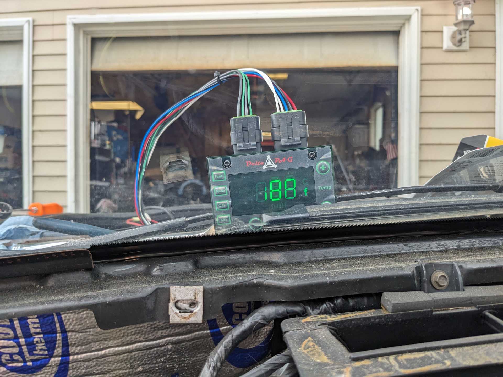
When the FAST saw a temp of 220, I cut the engine but left it at Accessory. The FAST temp dropped IMMEDIATELY to 203. The fan probe was at 188. So the delta shrank to 15 degrees.
Mike wants to replace the coolant temp sensor in the intake, which makes sense, but the overheating issue doesn't make sense. When the radiator intake hose is disconnected, that electric pump is GUSHING water out -- this was an accident, but it came out in a strong jet, lost about a gallon of coolant in the few seconds to go 'oh crap!' and turn the key off completely.
It's baffling and frustrating. At idle, the engine is not putting out any crazy horsepower, not at 1100-1200 RPMs. This radiator and fan should be keeping up with it. Given the force at which water expelled, I don't think we have any obstructions anywhere. If anyone has any thoughts, please let me know.
Also, if those pictures are gigantic, I'll resize and re-upload them. Just let me know.
[This message has been edited by Trinten (edited 06-20-2025).]
Vince, it is expected for the temps between the sensor in the front head (that is the stock location for the LS4) and one up by the radiator would be different. I wouldn't spend much time focused on that.
The coolant temp dropping/changing with the engine off or on, likely means one of two things: 1. When the engine is off, the water is falling away from the sensor. If it is in the stock head location, then likely means air is getting in the system. If the sensor is not in the head, then I would move it back to that location. 2. Potential ground issue between the ECM and the engine. The temp sensor should have a dedicated ground back to the ecm to avoid reading changes based on loads from other devices. If it is it grounded to the engine, then additional electrical loads could be messing with the reading when the engine is runnng.
I think what threw me off is the growing difference of what the engine temp was and what the sensor at the intake tube to the radiator was seeing.
I believe Mike said the engine temp sensor was in the stock location, I'll confirm tomorrow. If that is the case, do you think that we still have a nasty air pocket that isn't getting out from the vacuum fill and the steam ports (which run to a surge tank)?
Vince, the other thing to keep in mind is that heat transfer from the coolant passing through the coolant tube is dependent on the difference in temperatures from the ambient air and the coolant temps. So as coolant temps increase, there will be more heat transfer, so the difference in temps between the two sensors separated by the coolant tube would not be constant. After the car has sat for a week, the water coolant should be equalized, key on to see how different they are when you know the water temp is the same. If they are different then I would start checking resistance on the grounds between the two.
The FAST sensor should not have a significant change with engine running or just the key ON.
As we have discussed in email before, I am not a fan of rear mounted coolant surge tanks. Any hoses from your engine coolant fill point and the head steam line(s), need to go to the bottom of the surge tank, the surge tank should be higher than the coolant level of the engine, the surge tank can never go empty, and the surge tank should be pressurized (as the steam lines are free flowing), or you will pull air back into the coolant system and cause issues air pocket issues. What is your idle speed and timing?
What radiator cap pressure are you using? 220F is boiling at atmospheric pressure. The more pressure you run in the system the higher the engine can run on temperature without boiling the coolant medium. Are you using any cooling additives? Coolant is designed to retain heat not to disperse it. Water is the best cooling agent but you must add additive to protect the engine parts from rusting. I personally run this product.
Also, I know you were running the BMW water pump with the Tecomotive controller. Did you change to a Davis? The way your temps climb I believe you have air in your system and/or the system is not slowing the coolant enough for the radiator to get rid off the heat and send it back to the engine. If the pump is installed higher than the radiator it will cavitate and carry those air bubbles through the system creating havoc.
The surge tank should be the highest point for coolant. That's where Mike hooks up this device that pulls vacuum to -20psi, then the system sucks in coolant from a reservoir. We then top it off from the surge tank. Before flipping the fill lever, it does hold vacuum.
When everything is cold, Key-On-Engine-Off the coolant temps between the two sensors is zero to 1 degree.
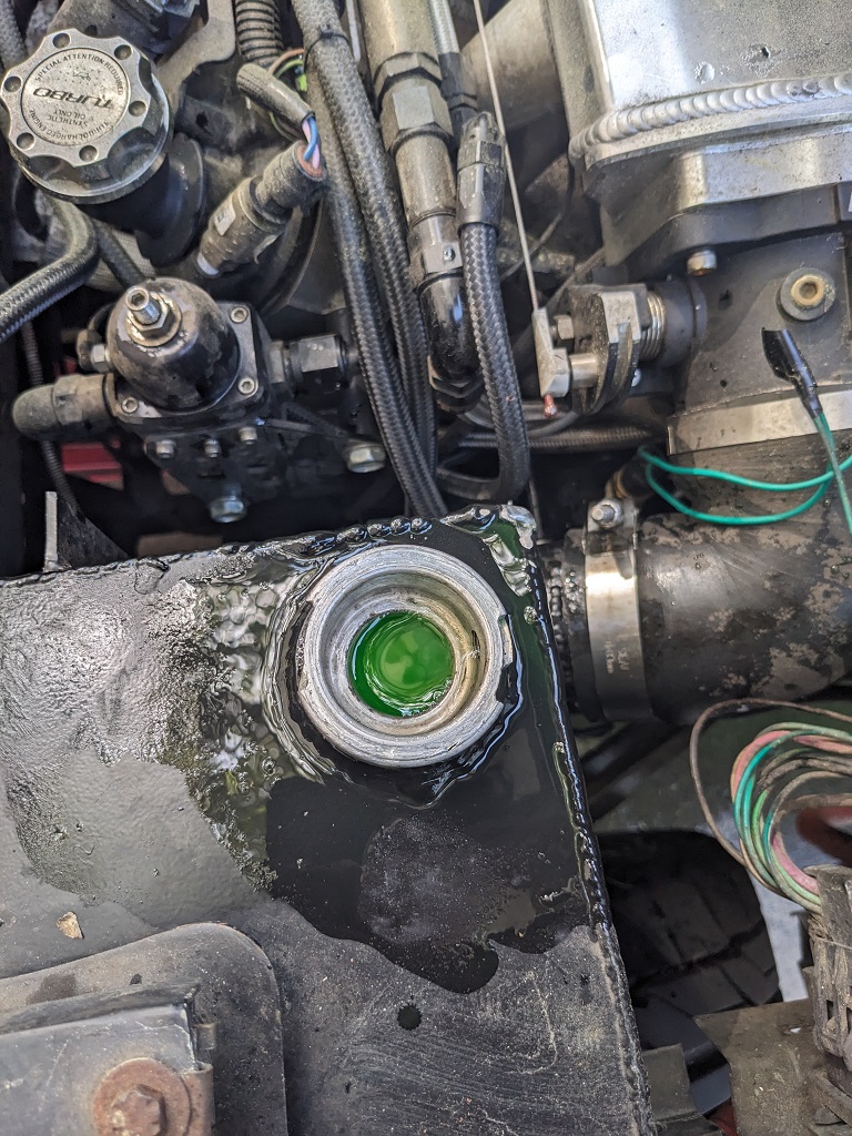
Coolant is in the surge tank (about half-way filled) when everything is off and cold. The surge tank has a radiator cap on it, it's 16 PS (Canton Racing part number 81-116). Could that PSI be too low? I *think* if we moved the surge tank to the front, it would be even lower than where it's at now (you'll see some pics of it by happenstance in the pictures below).
We switched to the Davies because after talking with Tecomotive and a few other people, they agreed the BMW pump I had was not sufficient, and pointed out how BMW guys that start modding their engines try to shoehorn in the next step-up of the BMW pump. Unfortunately that pump is not commonly available like the one I had, and it was more expensive than the Davies pump (by a considerable amount. Plus the Davies pump doesn't need a controller of any kind, so we switched to it. It does mean I still need to worry about the pump dying and not having an immediate replacement, but I'll buy another to keep in the car before going on any long trips.
I did add a bottle of surfactant (Water Wetter) to the coolant when we filled the system last year.
I asked Mike if it's possible if any obstruction could be in one of the channels in the engine (like a Mudgobber that got in there before we closed it up), he said it's unlikely, and given that we haven't warped either head or blew out a head gasket, and coolant flow seems good, he doesn't think that's an issue.
I'm going to see if anyone has a good thermal camera I can borrow, so we can check for unusual hot or cold spots.
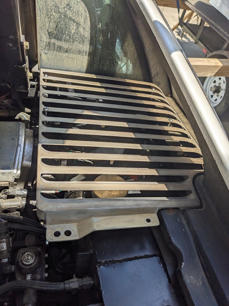
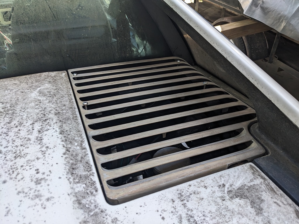
This past weekend Mike was fixing lights, wiring, and PM on hubs/brakes on a used trailer he bought that he's using next weekend, so we just worked on mounting the exhaust fan on the unpainted decklid vent I bought from the Fiero store.
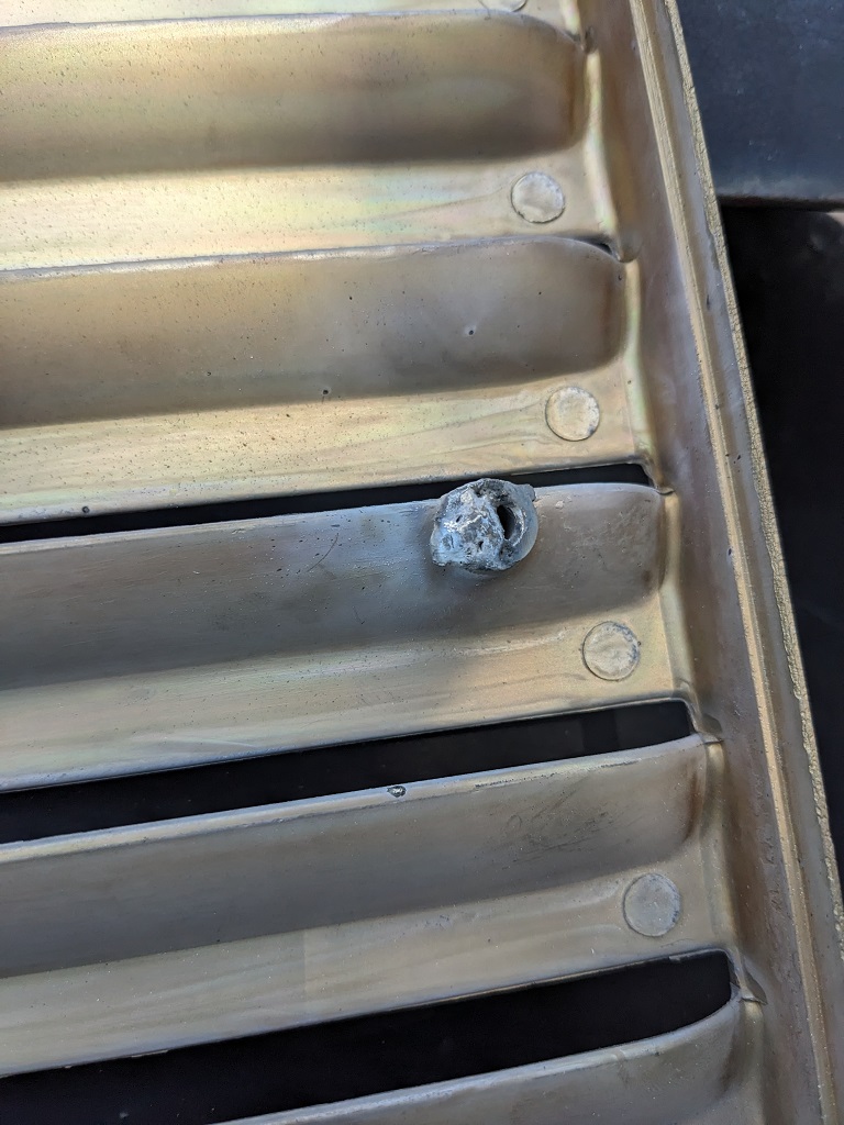
In the end we went with my original idea, which Mike wasn't thrilled with, which is to run bolts through the 'fins'. He wanted to weld in some better brackets. He took the vent and sanded off the bronze-ish coating off of one of the rivet stubs, beveled it, and tried to fill it with weld. The metal was not happy. It just sort of melted. He figures the alloy they used is basically junk "pot metal" which has a low melting point and is great for mass producing non-structural metal parts.
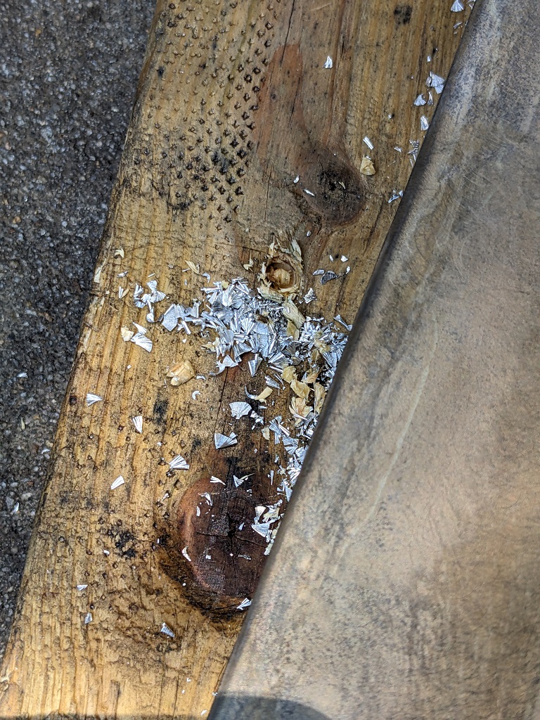
When he started to drill out the holes for me, the metal just flaked off, it never generated any 'strands' like you see with aluminum or steel. Flaking metal is another sign of it being pot metal.
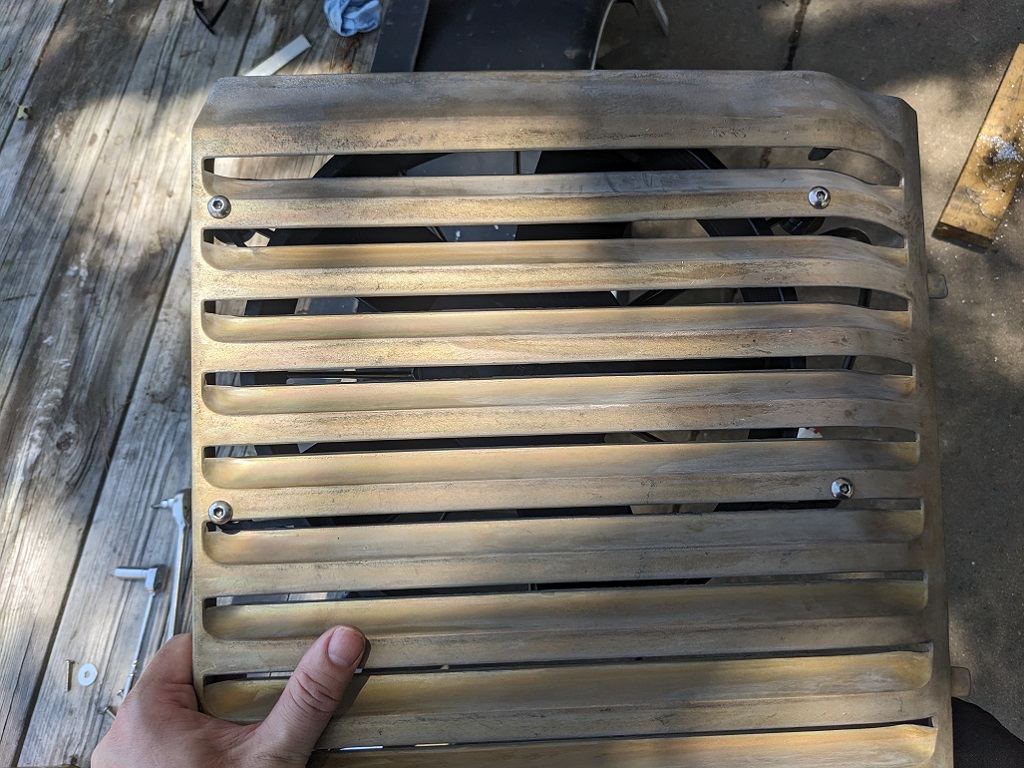
So I used some stainless button head bolts and nuts for test fitting. The nuts I had handy were nylon lock nuts, so they need to be swapped out.
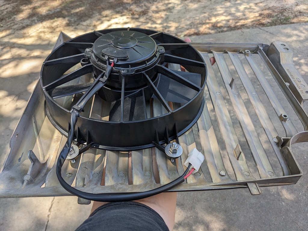
Then I did a final test fit. Everything clears!
Here's some underside shots, where you can see the clearance of the fan, and the surge tank in the foreground.
I snagged a great deal on a FLIR One Pro camera for Android. They run about 400 new, I got it for 160 on ebay. I was a little concerned, but it showed up and works great. The purpose of it is to try to find out if there's any unusual hot or cold spots in the coolant system. This camera has software specifically for this kind of stuff, and has two lenses so it can 'outline' objects to make them easier to differentiate on the captures. You can adjust the visual thermal range, mark multiple points, it's neat.
And I walked out of the house without it on Saturday. D'oh!
Without much else to do, I informed Mike that the consensus was we had a vacuum/pressure leak someplace. While we had used the vacuum tool he has to fill the system once before and it held vacuum, he couldn't rule it out since we had put in a new pipe for the temp sensor for the new fan. After he finished a little prep work on his trailer for one of those drag-and-drive-week competitions, we drained the coolant from the Fiero (used the plugs on each tube under the car, then the drain on the radiator).
He hooked up his vacuum to the surge tank, it pulled 20+ lbs of vacuum annnnd.... we heard burbling. This was new. We waited. Kept burbling. He pulled vacuum again. Still happening, so he went around and tightened up all the hose clamps. The burbling / vacuum drop slowed, but did not stop.
I asked what next. He said "I pull vacuum again, we use the port to fill it, then we pressurize the system and find the leak."
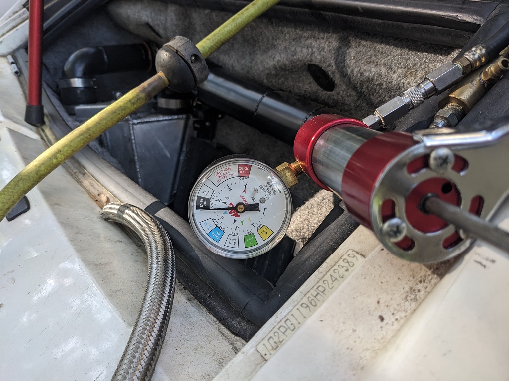
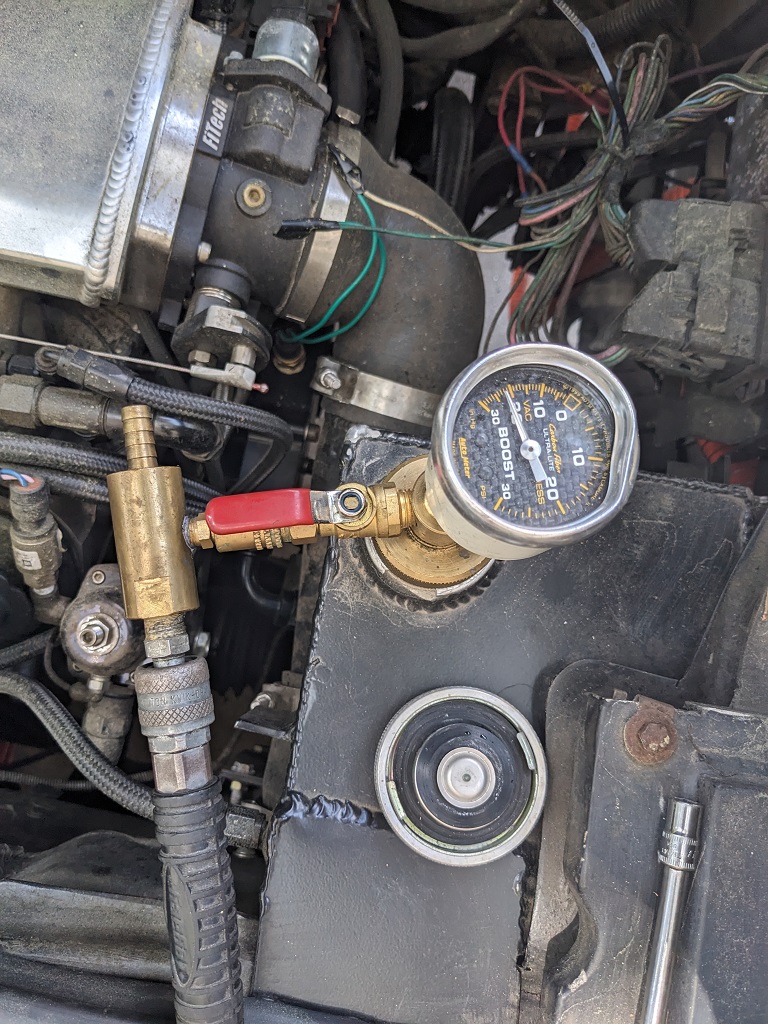
Here's the pressure device setup, pressure applied.
Thankfully, the only leak we found was right there at the AN drain fitting on the surge tank. We still left it hooked up for 15 minutes or so to make sure there were no other leaks. Mike inspected the hose and fitting and found the leak was not coming from the mating, but from where the AN fitting goes onto the hose. So he made a new hose. We re-presurrized the system, no more leaks.
He hooked up his vacuum system to it again and started pulling vacuum very slowly, he didn't want it to start ripping coolant out, since we had only lost the little bit out of the surge tank and it's return to the upper port on the water manifold.
It pulled to 20+ lbs of vacuum, and we waited... we cleaned up tools, talked about work, bourbon, life in general. 20+ minutes later...
So you see the port? That part pops off, and there's another one that clicks in with a second lever and another barbed port That's where the hose hooks up to put into the fluid you want the system to pull in by the vacuum. So we hooked the hose up, put it in a 5 gallon jug of coolant, and slowly opened up the port. I didn't get a shot of it setup with the filler hose clipped to the gauge/base.
Once it was done, the system was about as full as it can get
Optimistically, I jumped in the car and started it up... trunk was open (exhaust / puller fan is not wired up yet). Temps gradually climbed... it hit 175, the new fan kicked on full. The temp climb slowed. ... but still climbed. And climbed...
The time difference between now and before for it to hit 230+ was about the same, the outside temp was in the low 90s, so only a few degrees warmer than when we first tested the new fan.
We did the key on / engine off test again, and the FAST temp sensor (the one in the passenger side head) immediately did it's weird drop. (the fan temp sensor was still reading around 218, so about the same delta at higher temps as before). Here's a video of it.
Hopefully that opens okay for everyone. You can see it go from 233 to 206 in a few seconds.
Hopefully the FLIR will give me some insights into what's going on. If it doesn't... well, I guess I'll keep throwing parts at it. Maybe I'll get another CSR pump, which I had on my last Fiero and did great (it's currently trying to pump the intercooler coolant, but the pump is wearing out. We saw some chips in the vanes). At just idle, the radiator should be keeping up, even if it's undersized for operational use.
I did lookup and found some guys with the Pontiac GXPs did see around 215 when idling, but that was the outlier of the comments. Most said they saw normal operation around 220 when driving, and 199-210 when idling.
This hangup is really sapping my motivation. And I don't mind throwing money at my car, but damn, I like it to have a net positive effect.
[This message has been edited by Trinten (edited 07-14-2025).]
Just out of curiosity, how do you know you have the right amount of ignition timing taking into consideration the camshaft that you are using. Could it be possible ignition is on the retarded side causing higher temps on the exhaust and that heat can't get dissipated fast enough due to the amount of retarding of ignition? The more the ignition timing is retarded, the more heat you put on the exhaust valve water jacket area.
I know he referred to the cam spec sheet when we were first setting things up, and in the colder months when we could do drive-and-tune, he would be working in both the Spark Advance table and the Base VE table, seeing what the A/F ratio was, RPMs, engine responsiveness, etc. Though that was at side-street speeds and highway speeds (to a much lesser extent... except for last November when it was nice and cold and we put a solid 90 minutes of highway miles on it).
This is part of why I bought the thermal camera, so we can check out stuff like that and see how hot things are getting.
We can certainly play with the timing and the VE table. Right now it likes to be a little on the rich side during a cold start. Maybe if the timing was slightly advanced at lower RPMs, it wouldn't need to be so rich. I won't be out at Mike's this weekend. Next time I'm out there, I'll ask him. It can't hurt!
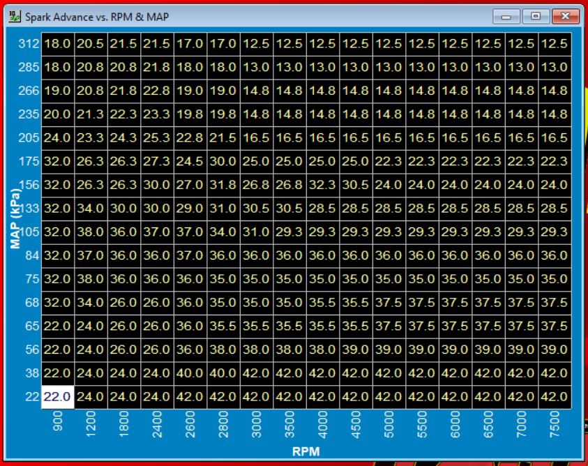
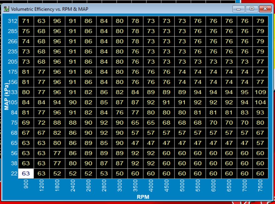
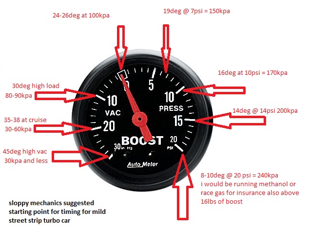
Vince, here are some timing maps I have used on my LS4.
This was the E67 naturally aspirated tune that was dyno'd. The cam was a 224-232 cam, which is a smaller than yours. The highlighed row is bacially WOT (100 kpa) and the lowest value is idle. It uses RPM and Cylinder Airmass, vs. KPA so it might not be easy to convert.
Here is the one I am currently running on my LS4 Turbo with the 219/223 cam (much smaller than yours). Dont be afraid to have 40+ degrees in the cruise areas.
Here is the idle timing:
When my car is at a hot idle @ 850 rpm, the timing is about 18-19 degrees.
Base maps on aftermarket ecms can be total garbage if they haven't done a lot of R&D for that application.
Is the "base ignition angle" in the second picture the same as the base volumetric efficiency table?
If so, my table is drastically different from yours (besides the layout being inverted).
I also tried to do some spot conversions for your spark table from (g) to kpa... I was not doing it right, the numbers it was spitting out when I converted mine to (g) were too far different to be plausible. Here's the two tables.
First up, my spark table.
And here is my Base VE table.
I don't seem to have a setting anywhere specifically for idle timing. My Idle specific options are: Throttle Follower Idle Speed vs Coolant Temp Start IAC Position vs Coolant Temp Timing Trim (which brings up a Spark Offset vs. Idle Speed graph where I can adjust the relationship curve) and Idle Parameters (IAC 'P' Gain, IA 'D' Gain, Max TPS for Idle (%), AC Idle Increase (RPM).
Originally posted by Trinten: First up, my spark table.
The base map looks like it came from a SBC with 35 degrees of timing at WOT, LS engine typically don't need over 27-29. The timing in boost seems agressive. Here is some general timing guidance:
Where does your engine idle? I assume it is around 1000 rpms and 60-70 kpa given the size of the cam.
Here is mine. The highlighted section is my idle range. 850 rpm @ 45ish kpa.
Don't focus on the actual values in the VE tables between the two, but more with the general shape - you don't want sharp dropoffs.
quote
Originally posted by Trinten: And here is my Base VE table.
The VE table still needs some work. Looks like there has been some adjustments in the part throttle/cruise areas as well as WOT up to 133 kpa range. I would start extrapolating and belending the area you have started tuning with some of the other untouched areas. It will just make the tune closer in those ranges when you get to the point of tuning them.
Here is mine for reference. I haven't gone much above 125 Kpa with this ecm yet.
[This message has been edited by fieroguru (edited 07-30-2025).]
The file we started with was an LS file that came with the FAST software. You are correct that there has been a lot of tweaking done by Mike when we would drive it around, including when he'd have me go to (or near) WOT.
The idle right now is 1100 to 1150. That is up from where it was in April, when I started messing around with the start-up tune. I made very small changes to the VE table (I would have to compare file versions to remember what they were, thankfully I save things with a date tag). Most of the change was with the throttle blade screw and TPS relearns. I opened it about 0.5 a turn.
There is also an after start table (in graph form) for Cranking Fuel vs. Coolant Temperature that I had tweaked.
Prior to making the tweaks above, the car would start with a fraction of a pedal press (basically starting around 1100-1200 RPM), and you had to keep it there for about 30 seconds before letting off the pedal, or it'd stumble and die.
I've tried adjusting the start IAC vs Coolant temp graph, but anything other than "wide open all the time" made the engine very difficult to start, even when reducing the fuel.
FAST also has After Start tables and other Spark modifier tables (like Spark offset vs. Fuel Energy Constant / vs. Inlet Air temp, / vs. Coolant temp) that I've tried doing adjustments to, testing, and if it didn't improve anything I put it back. I don't have the knowledge to confidently say "oh, if I change this on Table A, I need to also change variables on these other three tables to truly know if this helped".
I am learning, but have a way to go. Mike has shown me stuff by using his Grand National as an example. He'll change something in one table, the engine runs worse, then he shows me why based on an input from another table. It's a lot to try to take in and retain when you're only messing with it like, once a month (if that).
I will knock down the VE values in the area where my 'idle bubble' usually sits. Regarding it being aggressive under boost, the concern is knock? Right now we are running 92/93 octane, we haven't had any knock issues, thankfully.
I made it out to Mike's today, FieroGuru's tables in hand, and was like "hey, why did we retard the timing so much?" and he was really good about refreshing my memory "remember the surging issue we had because of the cam size? That's why." "Crap." then we got into why I asked, showed him FieroGuru's posts and such and he goes "Yeah, a smaller cam would play nicer, I told you we could switch out if you wanted to, and he's right there's a lot of other areas we need to put more time in."
So then he goes "I have something else about the cooling we need to check. I started the car up and was checking out the fan. It's only blowing air in a very narrow 'band', it's not pushing air the whole length of the blades to the hub, and the air isn't very hot. You put your hand behind the stock fan in my Fiero or GN, and it's HOT air. The GN fan is pushing more than the Fiero fan, but they're both pushing more, and it's hot. I want to put one of my extra GN fans on this today and see what happens."
"Umm. The GN fan is going to be too wide, I think." "We'll see." so he gets one - and it was too wide to mount normally, but putting it horizontally resulted in a pretty close fit with this radiator. The shroud at the bottom had a gap about 1/8" of an inch. This fan also has two bolts it uses to connect wires (which is wild to me), so we're going to do it quick and dirty, and hook it right to the battery. He gets everything ready, has me start it and tell him when the coolant hits 190. I do. He connects the ground, fan kicks on.... a minute passes, temp creeps up a little more... a little more, we get to 198... then it starts to drop.
Temp creeps down to 186, sometimes hovering back up to 188. So he unhooks the ground and tells me to let him know when it hits 210. It slowly climbed and went from 209 to 211. I tell him it hit, he hooks the ground, and for the first minute the temp still climbed, it got up to 218, then started to drop down again, getting down to 206-208.
So he said "we need to figure out how to make a good type of shroud and fit this fan in here." and I said "wait, this is a stock GN fan. Aren't these getting tough to find?" and he conceded "Well, it's not super easy to find them in good shape anymore." and I said "Okay, I don't want to carve up one of your GN fans. Let me get in touch with Delta and see what they say."
So tonight I did email them, let them know what was going on and that we had video and pictures showing the ineffectiveness of their fan compared to a stock fan from the 1980s, and I asked if they would be willing to look at it - maybe there's a defect that was missed and they can fix it. If not, or if no defect is found, I asked if it was still returnable (Their website simply says returns have a 20% restocking fee, nothing about how long or if it was used or not).
If they can't find an issue and won't let me do a return... well... at least I guess I have a nice PWM to control something in the future based on temperature.
I also asked him if one of his buddies (guy owns a commercial overhead door fabricating company) if they could mock up more of the shrouds my radiator came with, so we'd have a few to cut up to mount other fan options. He said they probably could. In the meantime, I need to see if I can find out how much CFM that GN stock fan pushes (or buy one of those cool CFM measuring devices), and start looking at other fan options... again.
OH!! Last big thing. He pointed out to me how when the coolant is cold, the pump is partially collapsing the rubber supply hose at the radiator. So he wants to go ahead and bump up the bungs at the 1.25" coolant pipes to -20s, and put a Y fitting that is -20 to two -16s, and run dual -16 hoses to and from the water manifold (it has the hookups to support it). He wants to see if improving flow efficiency is going to help first.
So, I get to order more AN stuff. lol I need to buy stock in Fragola and Vibrant.
Mike is taking one of his turbo buicks to Drag Week in Detroit next weekend, and something else the weekend after that,, so the next update is at least a few weeks out.
Thank you kind readers for sitting through another novella post. I do have some pics and video of the temperature tome foolery today, if anyone is seriously interested I can upload them.
Nice! Make sure you do the same test under load. Dropping temperature at idle is not the same as if the engine is being boosted under 75-100% load, at these loads the amount of heat increases exponentially. Is there any way that the fan can be programed to come on at say 210F at idle or below 60% engine load and as the load past 65% then the fan kicks in earlier; Something like 185F? That way the cooling system gets a head start on dissipating heat as the load/heat increases.
[This message has been edited by La fiera (edited 08-11-2025).]
Nice! Make sure you do the same test under load. Dropping temperature at idle is not the same as if the engine is being boosted under 75-100% load, at these loads the amount of heat increases exponentially. Is there any way that the fan can be programed to come on at say 210F at idle or below 60% engine load and as the load past 65% then the fan kicks in earlier; Something like 185F? That way the cooling system gets a head start on dissipating heat as the load/heat increases.
The controller the fan comes with lets you set two points, triggered by coolant temperature, and for each point you can set the fan intensity.
Delta PAG has been really good with working with me since I reached out to them with my concerns. The guy didn't try to do any blaming, he was really good about asking clear questions about the setup and being clear on why (and I get it, with the wiring harness they provide, the instructions clearly point out damage and problems that can happen if you hook things up incorrectly - the harness has wires that aren't use in every configuration).
He was also asking some of the same questions that were asked here, about the difference in temp between the two sensors, where they were and so on. He did ask what the coolant temp was on the inlet hose and immediately on the outlet hose. Which I didn't have yet (and forgot to get today. D'oh! ).
So they're showing a great willingness to work with me to try to get things right. So I'll continue to explore that soon (I have some trips coming up, I'll be traveling and putting discretionary funds into tthat).
I *thought* I had started another thread where I was asking questions on the instrument cluster and issues I had when bench testing the coolant gauge... but I can't seem to find the thread. So either I decided not to post it after typing it up, or it didn't post and I didn't notice it. Mentioning that in case someone finds my insane rambling where I'm wondering if the wiring diagram I had was wrong.
So Mike had put a two wire coolant temp sensor he had laying around (For a Grand National, of course) into the water manifold, and we had tried wiring it up to the coolant gauge, and it hadn't worked before. Thinking we had things right with the wiring (I probably was NOT on the right pin or something), I swapped out the IC (the one that came in this car originally was in rougher shape than my old one, so it worked out).
Today we were trying to figure out which wire in the trunk ran to that gauge. So at the IC, the wire is light green. But in the trunk... it's a different color green. Mike Ohm'd it out to find the right wire, and he wired it up.
Here's where it got odd. As the needle moved (yay!) I noticed it was off from what FAST was seeing. So he checked the ground wire he had temporarily connected. Asked me if anything changed. I told him no. He takes the ground off completely, asks me if it changed. I said "nope, still slowly climbing". We both thought for sure this sensor needed to a ground to work, and that once we pulled the ground, the needle would have either dropped back to 'cold' or pegged out. Neither happened.
We did realize later the temp difference was because that GN sensor uses a different Ohm range, so I need to get a Fiero one. Which is also two pin. So does anyone have any theories on why the gauge continued to worked properly after he disconnected the ground from the temporary sensor?
We also mounted the oil pressure sensor that will go to the Fiero gauge. We used the 88 sender, Standard Motor Products PS262. GM Part number 1808A. Putting the part numbers here because "sender" and "switch" are interchangeably used by various retailers for this part, and I have bought the wrong thing.
We didn't have time to wire up the oil pressure gauge today, so that will be next time. The new little length of hose and t-fitting Mike used (tapping into the line that feeds the turbo) didn't leak, which was great.
Even though the color scheme of the AN fittings is thrown off (there's now a stainless one in there, along with a blue "T" AN fitting, and mismatching hose segments), I might just leave it as a "last of list" item. It's not leaking. So if it works and is accurate when we get it hooked up... it can stay that way for now. lol. Too many times Mike will clean something up and get it all nice and sorted away, then something happens that makes us need to change it or things around it.
Next weekend I might see if he's up for getting the wiring from the FAST over to the IC Speedometer to get that working. I'm not worried about the Tach right now. Just be nice to have "the basics" (voltage, coolant temp, oil pressure, and speed) all working so I don't need to look at the FAST screen, which is not mounted in an ideal spot for the driver.
Which is also two pin. So does anyone have any theories on why the gauge continued to worked properly after he disconnected the ground from the temporary sensor?
The Fiero 2-pin temp sender for the gauges uses 1 wire for the gauge and 1 wire for the light. It grounds through the engine block to the chassis and back to the cluster.
The separate Fiero ECT sensor for the ECM is also 2-pin and grounded with a wire.
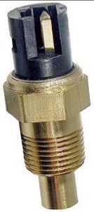
For the LS swaps, I use a 1998 Camaro LS1 3 wire coolant sensor in the head. It is a factory sensor with 2 wires for the ECM ECT and 1 analog wire to run the gauge on the dash (I don't worry about the light). It also has metric threads and is installed in the factory location in the head. https://www.amazon.com/Stan...oolant/dp/B000C81ZCM
quote
Originally posted by Trinten: We also mounted the oil pressure sensor that will go to the Fiero gauge. We used the 88 sender, Standard Motor Products PS262. GM Part number 1808A. Putting the part numbers here because "sender" and "switch" are interchangeably used by various retailers for this part, and I have bought the wrong thing.
We didn't have time to wire up the oil pressure gauge today, so that will be next time.
The oil pressure sender is a 3-wire setup with the two side wires being a N.O. pressure switch, and the center wire being for the gauge. It also is grounded through the block with only 1 wire going to the gauges. You do not need to worry about the switch capability as it isn't used with your current wiring.
quote
Originally posted by Trinten: Next weekend I might see if he's up for getting the wiring from the FAST over to the IC Speedometer to get that working. I'm not worried about the Tach right now. Just be nice to have "the basics" (voltage, coolant temp, oil pressure, and speed) all working so I don't need to look at the FAST screen, which is not mounted in an ideal spot for the driver.
If you plan on driving the Fiero speedo from the FAST ECM, then you will likely need to wire up this circuit to create the needed signal for the Fiero speedometer. You can also buy one here: https://reddevilriver.com/h...peedo-buffer-circuit
For the tach, you likely will need to get 2 things: 1. New tach board - yours is likely old and not reading right, and is calibrated for a V6 and not a V8: https://www.ebay.com/itm/14...Od%2Fj1MsH1w0hJhWlze gy9uz9PpQYc91mTxkHVzBaSix1TLxakBF0JiAXqbhWlYxq1c3VIeJt9%2FY12Uk5pgNrj2ZlUW4gX%2Bw67C%2FqF3chVBZWADfPMjLD%2FI3LsaoF024id1owExAFBNdb7KJLkHwT%2F4cD7OSvaOgHxbN3Jjs401IlTkvYcyvi57yh4nTxgHlA%2FVotnPhuhGNGGoYc%3D%7Ctkp%3ABk9SR5y_mMSbZg
2. You likely will need to wire in this circuit. It is OK to try it w/o first, but if it doesn't work try this:
Okay, so his sensor might have worked because - if I understand things right, it doesn't need the ground except to kick on the warning light?
The FAST temp sensor we have in the head is kind of a pain to get to, and having a third point to see temp / temp differences at various points is not a bad thing. I will get that Camaro one. I'm glad you told me that the Fiero's had two various coolant sensors! With my luck I would have wound up grabbing the wrong one. And now that you mention it and put up that picture... I am positive I bought one of those, because the PICO connector for it took forever to show up. I need to find that and let you know the part number to see if it's one I can use.
If we go with the Camaro unit, which pin is the correct one for the gauge? (thank you for the link to the right part!!)
For the speedometer, I have the FAST software set to do an output at 4k PPM for the gauge. What is the function of the circuit?
I see on Red Devil's site, the description is "Fiero 3800 Speedo Buffer Circuit. Used in Fiero Engine swaps. Allows PCM speedo output to be interfaced with the stock Fiero Speedometer." this doesn't explain if it's adjusting things to be 4k PPM, or doing something else?
Originally posted by Trinten: Okay, so his sensor might have worked because - if I understand things right, it doesn't need the ground except to kick on the warning light?
Both the sensor wire and the switch ground through the body of the sensor. So no ground wire is needed. The 2 wire sensor has 2 signal wires and 0 ground wires.
quote
Originally posted by Trinten: The FAST temp sensor we have in the head is kind of a pain to get to, and having a third point to see temp / temp differences at various points is not a bad thing. If we go with the Camaro unit, which pin is the correct one for the gauge? (thank you for the link to the right part!!)
Pin C is the analog signal wire for the temp gauge.
quote
Originally posted by Trinten: For the speedometer, I have the FAST software set to do an output at 4k PPM for the gauge. What is the function of the circuit?
It changes the type of the output signal to what the Fiero speedo needs to see. The ECM will create the 4000 ppm output, but the shape of the signwave will likely be incorrect and not work with the fiero speedo. This buffer circuit changes the shape of the output signal so it works with the fiero speedo. Every OBD2 GM ecm needs this circuit as well as the Haltech Rebel LS, so odds are your FAST unit will need it too.
[This message has been edited by fieroguru (edited 08-25-2025).]
So I have learned a disturbing amount on how coolant sensors work this week. For those that don't know.
1. There is the "GM Curve", where 0 ohms is hot, and 90 ohms is cold. Odd, but okay.
2. There are sensors made specifically for "short sweep" - which is the 90ish degree arm sweep of our coolant gauges (compared to 270 degrees, the other most common). One must make sure their sensor is for the right 'sweep'.
3. This one was a dead-stop... oh hell that make sense moment... even if you buy a sensor with the right 'curve' and 'sweep', the sensitivity might differ based on the max temp your gauge shows! So a sensor meant for a gauge that goes up to 300 (for example) will not show a correct value when feeding a gauge that goes up to 220!
It's wild stuff. Unfortunately it seems the LS1 sensor that FIeroGuru recommended has a thread of M12-1.5, and the opening currently on my water manifold is 3/8" NPT. This is likely why Mike grabbed a GN sensor, because the stock Fiero sensor is 5/8"-18 UNF (and yes, I did buy, and find, my stock coolant sensor and PICO connector).
I don't recall how much space is on the water manifold on each side of the existing port to know if we can drill/tap it open to take the LS1 coolant sensor, so in the meantime I'm trying to find another sensor that checks all of the 3 points above. It is not as easy as it you'd think.
I did find out that the speedo output sender is using a "Square wave" signal. So if that is the wrong type, I will need to build that buffer, as Red Devil shows it on back order.
Due to work kicking my butt and just generally feeling gradually defeated by my car, I'm going to do a combo recap and maybe correction.
My current cooling setup is using a dash -16 fitting on a 1.5" tube, coupled to the hard tube under the fiero with a standard coupler and clamps. The inlet is running that -16 line all the way up to a central inlet port on the current manifold, a -12, connected to it by a reducer. The output is via a single -12 line (this manifold has one -16 inlet, two -12 inlets, and two -12 outlets (on the sides).
We think we are having a flow issue, as mentioned before because the upper radiator hose would collapse from the suction until the coolant got hot enough and pressure popped it back out.
So, we decided to step things up a little. Peterson Fluid systems makes a -20AN to dual -12AN Y adapter. This will give us some flow increase. We will make a new coupler, putting the -20 end on that to/from the tubes under the car. These were not cheap, because -20AN to dual -12AN is not a big demand thing.
Of course.... AFTER I buy these, and extra -12 hose, etc etc... I discover that now there are many more affordable 4 port -16AN LS water manifolds out there. *sigh*. Anyway. I figure we can try what I bought. So we go about trying to set all this up.... and discover that even with the current 1" spacers, the AN fitting for the port on the side will not clear the accessory adapter plate and bolt. So it needs to come out another 1.5" (2.5" in total). I can't FIND a 2.5" LS style spacer. Just a 3".
So we may need to see if that will fit, and if not, buy it and take them to a machine shop to put in a portland and shave the damn things down.
At least after all this, if we still have issues, I know I can save up for another $300-500 manifold that has quad -16 ports (and -20 to -16 Y adapters are much more common and affordable). Downside is most of them only have 1/8 NPT ports besides those, which will be a restriction from the surge tank, and mean I'll have to change up the coolant sensor I put there (I think).
Ooooor.... I need to see if I can convince FieroGuru to plasma cut/mill out something awesome for me. *cough* plan c *cough*.
On the upside, I found my Aux gauge cluster! So we can check to see if the oil pressure sensor is working properly. OH, and I saw on ebay someone was selling a new faceplate for that cluster that hoses three 2.125" ports. So I might get that and pick up other gauges to put in that, along with my transmission temp gauge I got from speedhut a few years back.
The upside is, with the colder weather around the corner, we can do longer drives like we did at the start of this year and Mike can smooth out all those spots in the tune.
Also, sorry for not embedding the pictures... I am just kind of at zero-Fs right now, so I just linked them from my google drive. If you guys can't see them, I'll fix it when I have the energy.