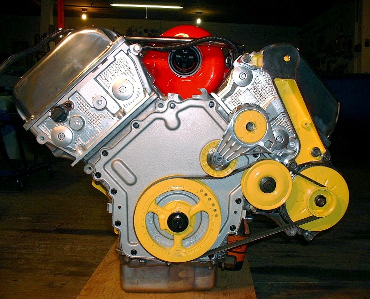
Interesting, my Aurora fuel rail was mostly straight. Straight enough that I decided to leave the stock quick connect fittings on and run it as is. I bought it and the pr new so I did not have to worry about it being gummed up. The regulators should be nearly, if not, the same. I know that Russ found some slight difference in the ones he had and my new one but not enough for me to be concerned. The engine looks awesome. I did not think about the idler being on the other side of the belt... When I bought my PS delete pulley I just went to the local auto parts store and bought a Dayco brand. Hopefully it'll last a while. Good luck getting the "perfect" length belt.
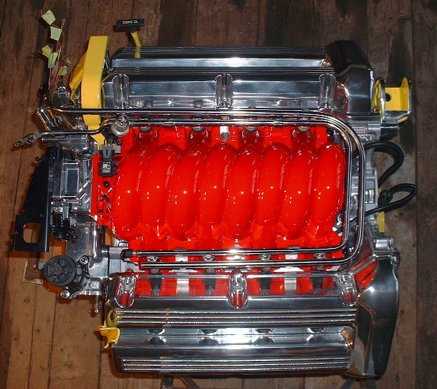
Bingo, Jefrysuko figured it out! Just kidding... Erik was right. I kinda figured it would take someone with a Northstar to spot the difference. I wanted to finish off the "cleaned-up" manifold look by hiding the wire harness to the injectors. My first thoughts were to run them underneath the intake in the valley between the cylinders, but that would've meant having to drill additional holes in the plastic somewhere to get them on the right side of the manifold again. The space is there to do it, but I wasn't keen on removing some of the webbing under the manifold to accomplish it that way.
So, on to door number 2: stainless tubing. I figured by mimicking the contour of the fuel rail with a second stainless tube, it would fool most people into thinking it's part of the stock fuel system, like a return line or something. The fuel rail is 1/2" OD, so I didn't want to go any larger than that if possible, so I played around with some carbon steel tubing just to see if I could bend it with the right radii, and if all 19 wires would be able to fit into that tight little tunnel. That's where the first hurdle was. The steel tubing had 3/32" wall thickness and was just too tight to fit them all in. After about a week's worth of looking everywhere (on-line, locally, nationally, etc) I finally found a source for some stainless tubing 1/2" OD with 0.065" wall thickness for about $1.25 a foot! Considering that the only other places I could find 1/2" OD stainless was at a medical supplies store for over $170 for a 4' length, I figure I lucked-in.
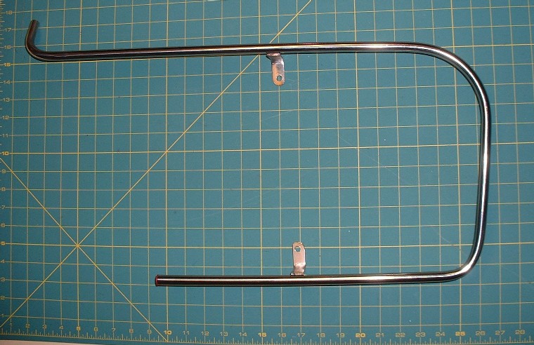
So the first step was to bend it and mock up some stainless legs to hold it at the right height on the manifold. Interstingly, the fuel rail doesn't have two 90* bends in it. It actually is angled along the bottom of the U to follow the angle of the intake runner:
I kind of knew that two legs wouldn't be enough, and was right, so I fabbed up another leg and welded it on to keep the whole thing from teeter-tottering.
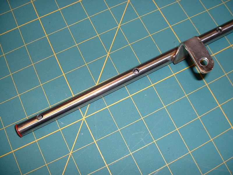
Next, with it temporarily installed on the manifold, I marked where the wires would need to come out of the tube to mate with the injectors themselves, and then drilled, and chamfered the holes to keep the edges from chaffing the insulation.
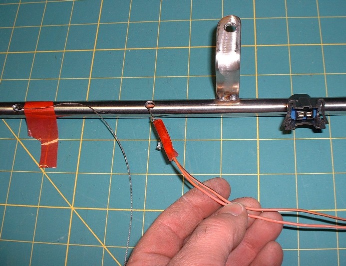
The hardest part was actually threading the wires for the injectors through the tube. At first I thought they'd all just slip inside and everything would be hunky-dorey. Not so. There's enough room inside the tube, but only just enough so the last four wires get really tight. Then I tried fisching them through with extra-tough strings like in the photo below, but there was no way to adequately fasten the end of each pair of injector wires to the string without the string pulling off towards the end. Lastly (and successfully), I threaded one sacrificial spare wire as a fische through each small hole until it emerged from the end of the tube, then soldered each pair of injector wires to it's respective fiche wire to hold it securely, and was finally able to pull each pair through... but not before a lot of silicone spray lube was used up and a lot of swear-words for the last three MAP sensor wires. I then tested each wire end-to-end for continuity just in case I broke any wires internally, and checked each wire to make sure it wasn't shorting to the tube either, but all was good.
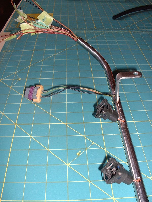
Here's a close up of how the wires and connectors protrude out of the tube. I'll still need to squeeze a dab of silicone sealant into each of the small holes to act as both a sealant and a grommet to protect from the steel edges.
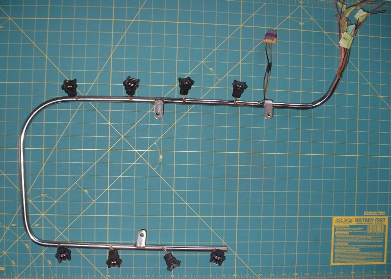
And here's a view of the whole harness tube ready to install on the manifold:
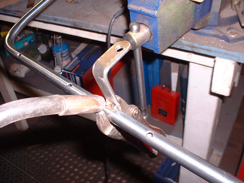
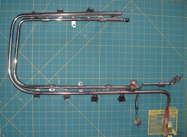
Here's how it mates up with the fuel rail to look like it's an integral part of the design. I opted to weld the little legs of the harness tube in such a way that they pick up different fasteners than the fuel rail does since to do otherwise, it would've been difficult to tighten the fuel rail fasteners with the harness tube in the way.
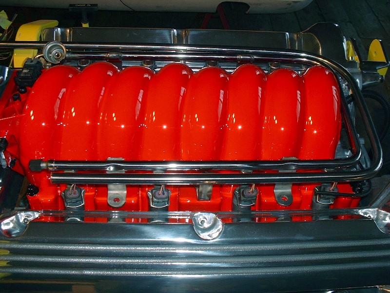
Finally, here's another angle of the whole schemozzle temporarily installed on the manifold as I wait for my good injectors to make their way back to me from a cleaning and rebuilding somewhere in the good ol' US of A. Nice and clean with no wires showing, eh?
That"s badass really cleans up the look! I might just do that on my ITB setup thanks for the great idea. Your engine is the best looking one on the forum.
A most incredible build. Keep up the great work. I just bought an F40 6SP and just started planning my swap. I have decided on which engine yet. I look forward to how you address clutch/pp, flywheel and axles. Keep going I just can't wait.
you my good friend are a REAL technician. the entire industry has gone the route of parts changing. i think there can still be a market for real mechanic/tech work and doing it right. following and extremely interested. love the work. i work at a gm dealer and have never seen anyone even try to use ingenuity like yours. best of luck to you. oh and gm reccomends mobil 1 in all the updated northstars with the 305hp rating... ever notice that?
------------------ 1985 gt notchie auto (pic)| 3800 SFI N/A coming soon 1986 se notchie standard 4spd | 5.3 vortec soon
I think most people would agree that your Northstar with the ITB’s is going to be the best looking engine on Pennocks! That thing just screams exotica.
quote
Originally posted by bowrapennocks:
I look forward to how you address clutch/pp, flywheel and axles. Keep going I just can't wait.
This is my last post on accessories and I’ll move onto the transmission and axles next.
quote
Originally posted by BlackGT Codde:
gm reccomends mobil 1 in all the updated northstars
Thanks for the compliments and for the tip. I was planning on using synthetic oil in this engine after the initial break-in.
As for aeffertz and neverendingproject (NEP for short!), I appreciate your kind words. For Custom2M4, read on... I'd like to know what belt you used.
So then, just to finish off last week’s series of pictures, here’s how I terminated the injector harness wires sticking out of the stainless tube. I had originally thought I’d be able to unplug the connector pins from the back of the connector and fiche them along with the wires through the tube, but there just wasn’t enough room. I made a quick schematic before cutting it off knowing that I’d be in for an hour or so of splicing and soldering it back on the loose wires.
With that done, I waited for the next nice day (it’s been raining for a week now) before heading out to one of the local junkyards in search of a 3.5” idler pulley with grooves to replace the Caddy smooth idler. I think I looked under the hood of every car on the lot before finally finding a ’95 Ford Contour with a 16 valve Zetek engine that had just what I was looking for. The pulley came off of the Contour’s tensioner, not to be confused with the Contour’s idler, which was smooth.
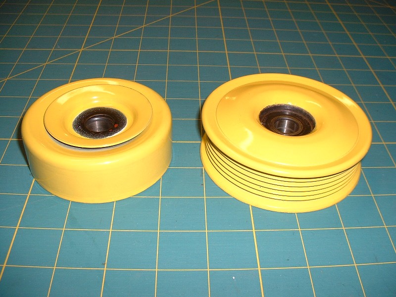
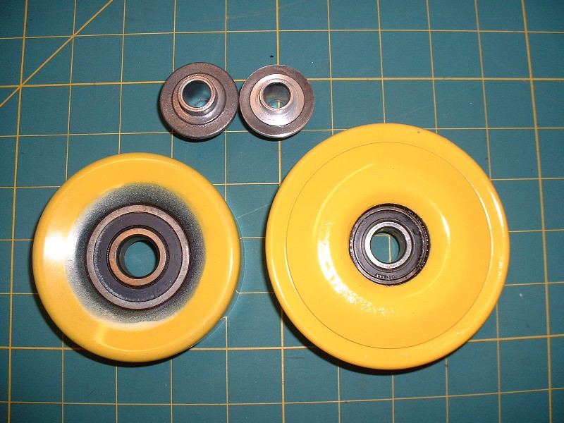
It was in great shape but clearly the wrong color so once I got it home, I pressed the center bearing out of it, bead-blasted, primed, and painted the pulley. Here’s the Caddy idler on the left and the Ford is on the right.
The two pulleys are remarkably similar dimensionally except that the Contour pulley has a much smaller bearing, both ID and OD. The photo below shows the Contour pulley and the Caddy mounting bolt and spacer. The spacer locates the pulley the correct distance away from the block to line up the grooves with the other pulleys. The problem is that the Contour pulley won’t fit on the Caddy bolt and spacer because the Contour’s bearing ID is too small.
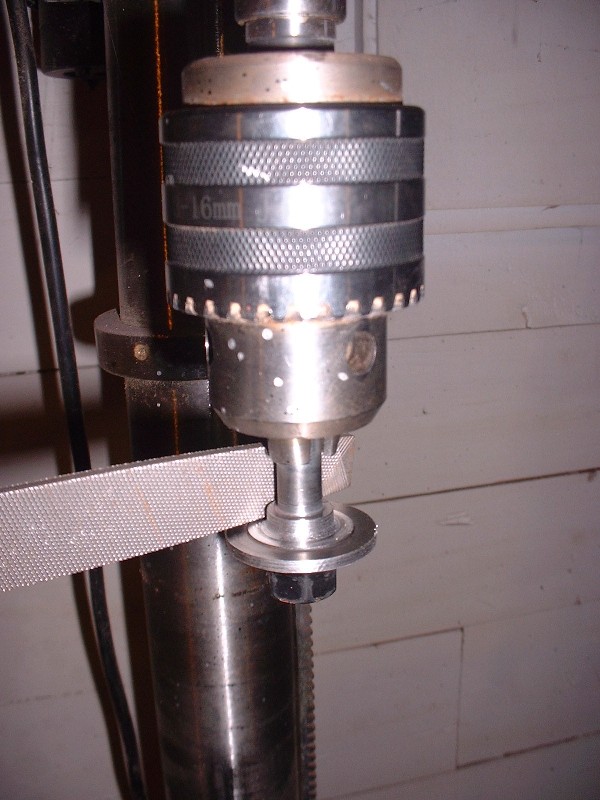
To correct this minor problem, I used the poor-man’s lathe and machined the collars on the Caddy bolt and spacer down from 0.662” to 0.590”, which made a nice fit inside the Contour’s bearing.
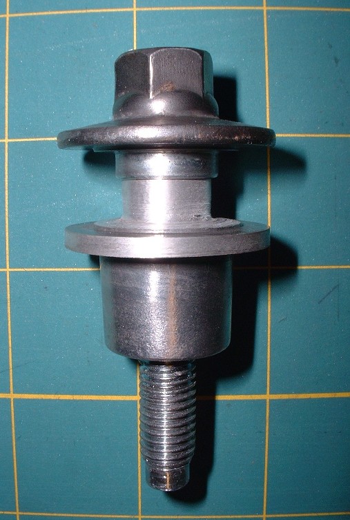
The next issue was the diameter of the Caddy bolt and spacer’s integral washers. They were too big and when installed, contacted the part of the pulley that needed to rotate, so I chucked them up in my drill press again and machined them down from 1.420” to 1.340”. Here’s a picture of the two pieces where only the spacer (the lower part) is machined down in both areas as compared to the bolt which is still the original size:
Here’s another view of the discarded Caddy idler on the left with an unmodified spacer from my spare engine above it, and the Ford tensioner pulley on the right with the modified spacer above it. It’s hard to see the differences in the bearing inside diameters but if you look at the spacers carefully, it’s clear. One last tidbit before the Ford pulley would line up properly is that the bearing must be pressed into the pulley so that it’s flush with the back side of the pulley’s center bore. This provides the correct offset.
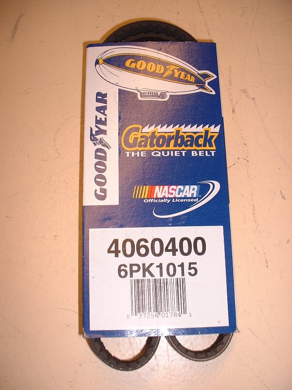
Finding a correctly sized belt was a lot easier than I expected, it just took a lot of sweat to figure out that I actually had the right one. I temporarily installed all of the belt drive system on the engine and carefully measured the planned route of the belt using the original Caddy belt, which is waaaay too long. I calculated that the new belt would need to be an odd-ball 40.5” long... oh great (sigh). I crossed my fingers and called the local auto parts store and luckily they had a six-rib Dayco at exactly 40.5” (part number 5060405). For good measure, I also brought home a Goodyear Gatorback that was 40” (part number 4060400).
After routing the 40.5” belt the way I had originally intended, the tensioner was up against it’s stops (vrtually useless) and the belt wasn’t especially tight. So next I tried the 40” belt and worked like a dog at installing it for what seemed like an hour without any luck… it was just too tight to get on the pulleys no matter how I tried. It’s hard to believe that a half inch one way or the other could result in too much slack or not enough. So then I tried Custom2M4’s idea of reverting back to the stock Caddy smooth idler from my spare engine and running the belt under the idler and ditching the tensioner (I really really wanted to use the tensioner after having spent countless hours polishing it though!) But, neither belt was long enough to reach in that configuration either. I don’t know what belt Custom2M4 used, but the 40.5” was too short and the next size up (46” I believe) was clearly going to be too long.
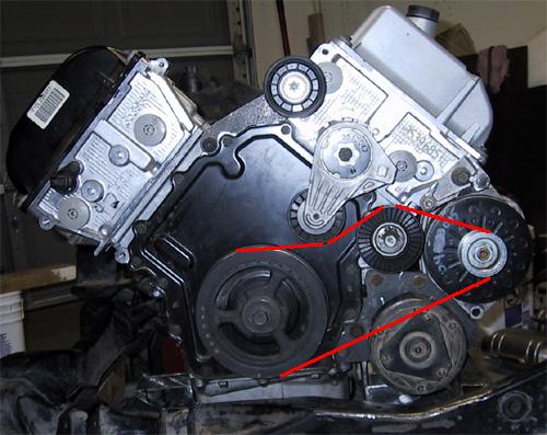
Finally, I retried my original idea with the 40” belt, only this time I changed the order which I installed things, and it worked. Here’s the trick for anyone duplicating my configuration: First, have only the crank pulley and alternator pulley installed, and slip the belt on those two. Next, slide the modified Caddy idler bolt part way through the Contour pulley and screw the spacer partly on the backside. Then place the idler pulley under the belt and reef up on it as hard as you can to align the bolt with the hole on the block, while a second person screws the bolt. At this point the belt is quite tight and it’s no wonder there wasn’t enough slack to pull the belt over the ridges on the idler when I tried it the first time with the idler already installed. Lastly, to get the tensioner on, there’s only one way. It’s held in place by one bolt but it has an integral pin on the backside that mates with a hole in the block to keep it from spinning on the one bolt. To get the tensioner on, don’t stick the pin in the hole and try to lever the bolt to line up with it’s hole, instead, screw the center bolt into the block part way first. Then, using a ½” ratchet wrench in the square hole on the tensioner arm, rotate the entire tensioner about the center bolt’s axis until the pin lines up with it’s mating hole in the block. At this point the tensioner will be under a lot of tension so you may need someone else to finish tightening the center bolt, drawing the pin into it’s hole at the same time. Here’s the final belt routing:
The Contour’s pulley comes within 1/8” of the Caddy alternator fan (arrow B), but it should be enough clearance not to make contact. The only other issue is with one of the bolts that hold the dog bone bracket to the block (arrow A). I’ll have to replace that bolt with a pan-head bolt to get the necessary clearance… right now it’s touching the belt.
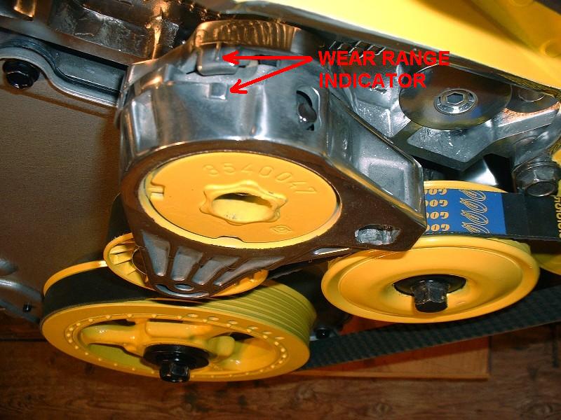
Finally, once I had cycled the tensioner arm a couple times using a ratchet in the square hole, the tensioner settled into a nice spot exactly within the range it was designed to operate in. The picture below shows the little pointer on the stationary part of the tensioner hub pointing at the small raised square that indicates the center of the tensioner arm’s travel. And what you don’t see, is the smile on my face knowing that the engine is basically done .
EDITED TO ADD:
To solve the interefence between the belt and one of the bolts pictured above, I considered advice from Bubbajoe to buy an allen-keyed socket head bolt and countersink it into the aluminium dogbone mount. Once I had a closer look though, there simply wasn't enough material thickness to the mount to do this. Instead, I used a low profile panhead bolt and gained the needed clearance.
[This message has been edited by Bloozberry (edited 11-14-2010).]
Thanks Charlie. As for Dratts... I think this car is going to be a fair-weather baby... and we have clean roads in Nova Scotia (well... until harvest time that is.) Bubbajoe, that is a great idea. I'll post an updated photo when I get around to doing just what you said.
And now… for the transmission. Most people reading this thread are well aware of the incredible deals that were to be had starting about a year ago on Pontiac G6 transmissions, but for those tuning in for the first time, here’s a brief summary. In 2006, Pontiac offered a new higher-powered version of the G6 sport sedan called the GTP. The GTP had a 240 horsepower 3.9 L V6 with variable valve timing which came standard with a four-speed automatic transmission, but for no cost, a six-speed manual transmission was available. The transmissions fabricated by GME in Germany are known as the F40 (RPO code MT2) and came with the following gear ratios: 3.77 / 2.04 / 1.32 / 0.95 / 0.76 / 0.62 / Rev 3.54 with an axle ratio of 3.55 which gave a final drive raito (in top gear) of 2.51:1. The torque capacity was officially rated at 295 lbft.
These transmissions however were superseded in 2007 with ones having slightly different ratios and a few improvements to counter noise complaints, resulting in a surplus of F40’s. Sometime in 2008 these surplus transmissions started appearing for retail sale through a number of online sites for approximately $400 - $500, an incredible deal considering they were brand new, and worth between $4000 - $5000 in 2007. I bought mine from a company in Michigan called Schram Auto Parts for a grand total of $666 including shipping, duties and taxes.
The nice thing about the F40 and the Cadillac Northstar, as many people know, is that they have nearly compatible bellhousing patterns. The major differences are the starter locations, a slight interference with the Northstar’s rear mounted coolant manifold, and one bolt hole that doesn’t line up with the rest. The F40 and the Northstar have been mated successfully by several people here on PFF and the next couple posts will really only be duplicating what has already been done before. The difference is that I hope to provide a bit more detail on how to go about doing the necessary mods.
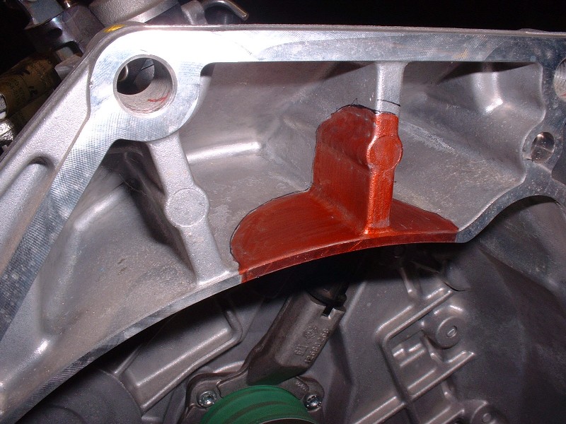
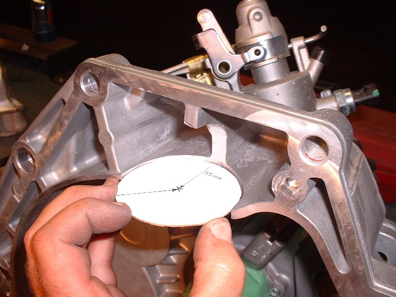
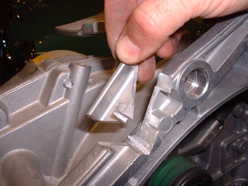
So then, the first thing that needed to be done was to sit down with a ruler, a compass, and some cardboard to make a template of the F40’s bellhousing flange. With a mock-up traced out, and using the top two mounting holes, I then transferred the template to the rear of the Northstar. That’s when I first noticed the interference with the water log and carefully trimmed out the triangular piece to the left of the picture. Then I measured the location of the starter snout on the engine in relation to the top two bolt holes and traced it onto the template so I could transfer the starter location back to the F40.
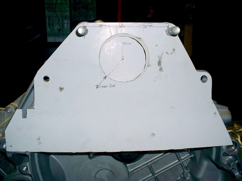
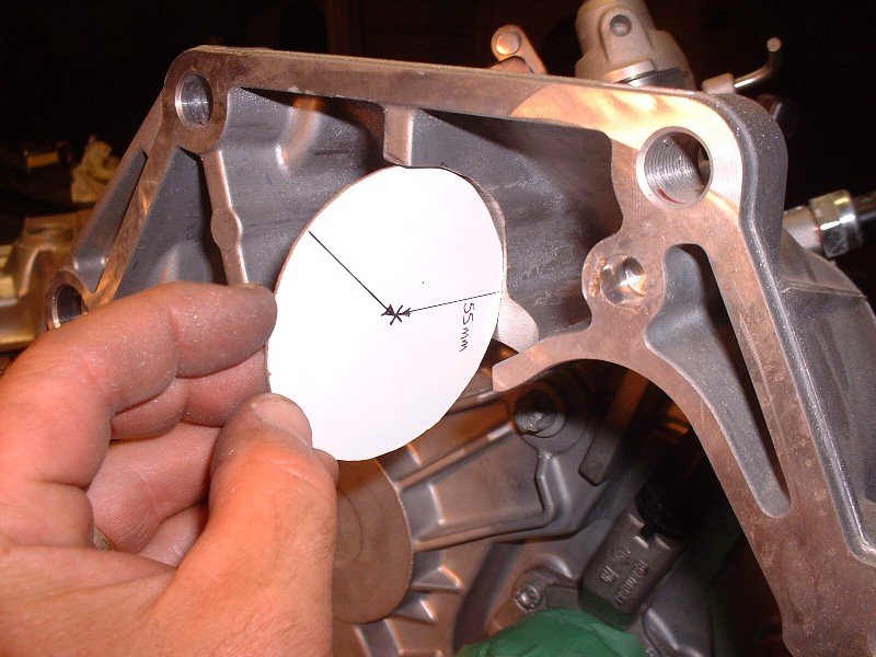
Here are the critical dimensions for anyone doing this in the future. Basically locate the center of starter hole 58mm to the right of the top left bolt as viewed from the bellhousing side of the transmission. Then, drop 55mm down at 90* from the top edge of the bellhousing to locate the center of the starter. Use that point to draw a 70mm diameter circle (35mm radius), which is just large enough to clear the diameter of the starter snout.
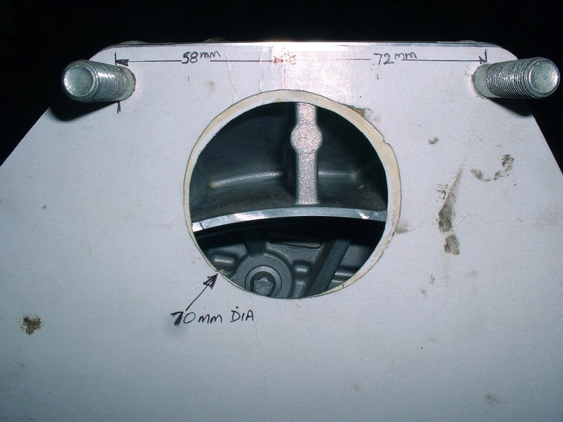
Use an exacto knife or something similar to cut out the hole since you’ll need to keep the circle for later. Next, test fit the template on the engine to be sure the starter hole is properly located. Once satisfied I had the hole in the right place (if you look carefully, it took me two tries!), I relocated the template back on the transmission using the two top bolts, and colored the edges of the webs that I could see through the starter hole using a red marker. Notice that the hole isn’t centered on the vertical web of the transmission.
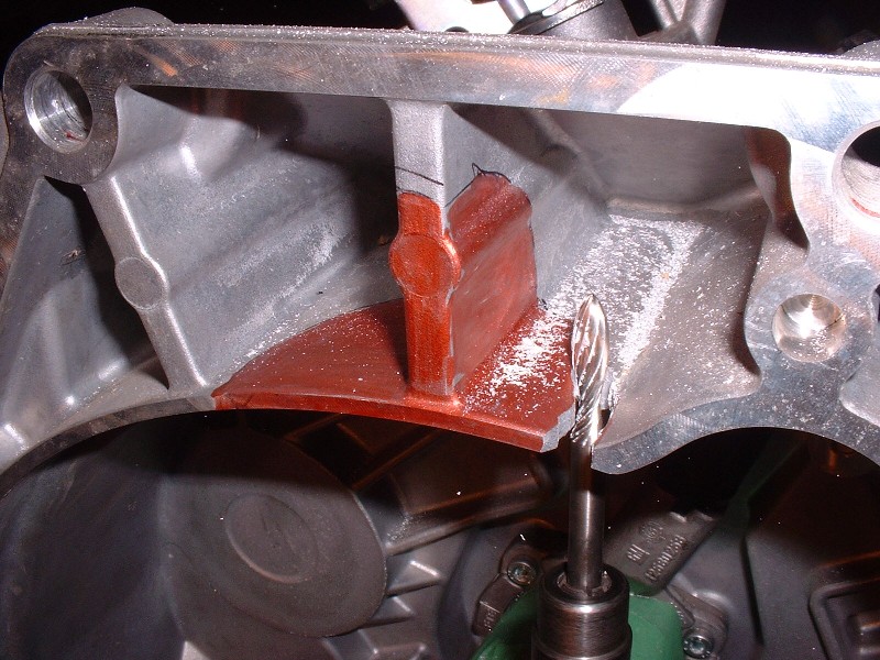
Then, to locate the depth of the starter notch on the horizontal web, I took the 70mm round hole I cut out earlier, drew a line through the center of it, and used it to trace a half circle under the horizontal web, lining it up on the red marks I had made earlier. Finally, to get the right depth of the notch on the vertical web, I just measured 35mm from the machined edge back along the intersection of the two webs and then eyeballed the quarter round shape using that mark and the one made earlier on the vertical web using the template. If you can’t follow what I just wrote, then this picture should help:
The next step was what I thought would be the easy part: cuting out the notch. Ha! That aluminium is hard! I first started with a fluted grinding bit on my die grinder and it worked OK for the first bit but then galled up with semi-molten aluminium.
Next, I tried what I call a Zippy-tool… it’s basically a dremel on steroids that uses special bits that look sort of like drill bits, except they’re made to be used like a router. That thing made the going a little easier, but it still took me close to 1.5 hours to do it right, and not have it looking like some butcher with a sawzall did it. The most difficult part was the vertical web since there isn’t a lot of room to manouvre.
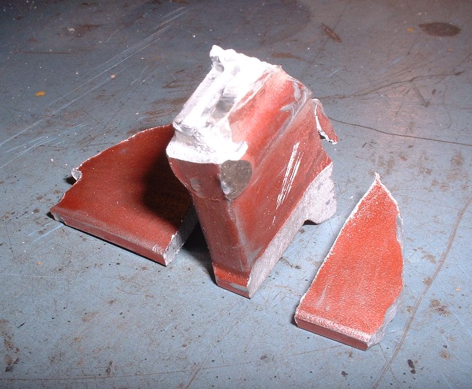
Here are the parts (finally) out of the way:
And here I am test fitting the 70mm circle to be certain I cut enough material away both horizontally and vertically.
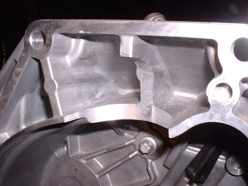
Lastly, here is the nicely finished notch once I was satisfied the profile was right and after I cleaned the edges with a 2” sanding drum.
[This message has been edited by Bloozberry (edited 11-11-2010).]
(Just a quick side note here: for those that are interested, I edited an earlier post on this page by adding a photo of how I resolved the interference between the serpentine belt and the head of a bolt.)
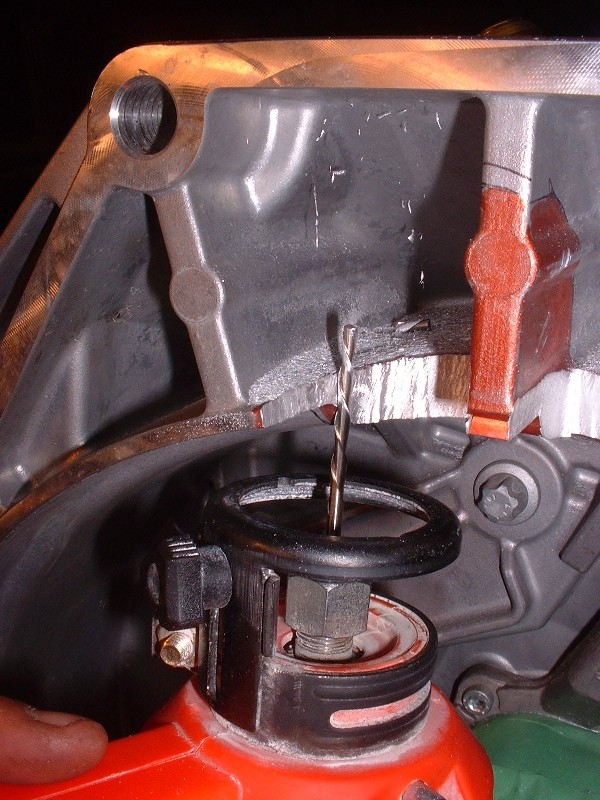
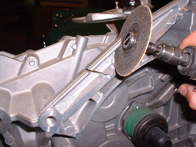
Next on the “to-do” list was to cut the triangular wedge out of the bellhousing to clear the water manifold at the back of the engine. I simply traced the outline from the template I made earlier onto the bellhousing. Then, to make a nicer radius at the corner where the two cuts meet, I first drilled a hole. I used a cutoff wheel on my die grinder to make the cuts and it went fairly well:
Here’s the little piece once it was cut out. I later used a file and smoothed out the freshly cut surfaces.
With those two modifications done, it was finally time to test-fit the transmission to the engine! The F40 weighs 123.5 lbs wet, according to literature… (they’re only shipped with a small amount of oil in them) so they’re easy enough for one person to handle. When I slid it on, the two alignment dowels on the engine gave me a little grief, but apart from that, it went on with only a small hitch. There’s an engine sensor of some kind (not sure what it’s for yet) on the side of the engine block, in-line with the triangular cut-out on the transmission. The sensor doesn’t interfere, but a spring-clip holding the sensor wraps around to the bellhousing face that gets in the way. For now, I just bent the clip away. Here’s the assembly.
And a top view. It’s amazing how much of the transmission disappears under the water manifold before finally mating up with the bellhousing face of the block. My next big decision is what to do to refinish the transmission. I’m not polishing it, that’s for sure, and I don’t feel like taking it apart to have it powder coated, so painting it to keep it looking fresh might be the solution… but I’m undecided.
Here’s a close up of the area on the transmission where the triangular notch was cut out to clear the water log. I purposefully made it as tight as possible to avoid the appearance of an aftermarket mod.
Those eagle-eyed among you may have noticed an extra piece of hardware in one of the pictures above. Well here it is:
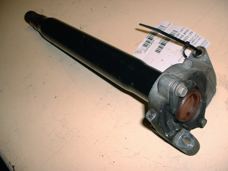
When I travelled up to Ottawa for the Roger Waters concert a month ago, I took a detour up to Ste Sophie in the Quebec Laurentians. The only used parts dealer on Car-Part.com in all of Eastern Canada that listed a Saturn Ion / Chevy Cobalt SS jackshaft was up there. This one is actually from a 2007 Ion. Not including the cost of the detour, it was $108 after taxes.
Zac88GT came up with an ingenious way to mount the jackshaft bearing carrier to the Northstar here about 2/3 of the way down the page: www.fiero.nl/forum/Archives...100421-2-086234.html but I decided to do things a little differently. Over the next couple posts I’ll cover what I’m doing, as well as the mods to be able to use as many of the bellhousing bolt holes as possible since some of them aren’t threaded and one doesn’t line up.
I vote for leaving the trans as is. If it isn't seeing salt (or much moisture, for that matter) it won't get funky and should be fairly easy to keep clean.
With the transmission-to-engine installation mocked up, there’s tons of measurements to take for future reference to help determine where on the cradle the powertrain can potentially be installed. The most important one is fore and aft axle alignment in relation to the hubs. Unlike universal joints, CV joints don’t mind running at angles but even so, the idea of placing the transmission output shafts in line with the wheel bearings is to prevent the axle from becoming the limiting factor for suspension travel. With that in mind, I needed to get the jackshaft rigged up so that I would have a much better ability to measure and line up the transmission output shaft in relation to the passenger side hub, which is a long, long way away from the transmission!
I decided to use a jackshaft primarily because I am widening the track width of the car by 3” on each side. Without a jackshaft, this would have meant trying to find a passenger side axle that is about 4” longer than the stock Fiero axle. (The extra inch comes into play because the F40 differential is also shifted 1” further to the driver’s side of the car in relation to the bellhousing surface.) I don’t think I would’ve been able to find any such beast without expensive custom fabrication. Using the jackshaft, it will be easy to find an axle with one set of splines already matched to my needs, and the most it will need is shortening and splines machined on the other end. This will be considerably cheaper than buying a totally new custom-made extra long axle. There are other benefits too.
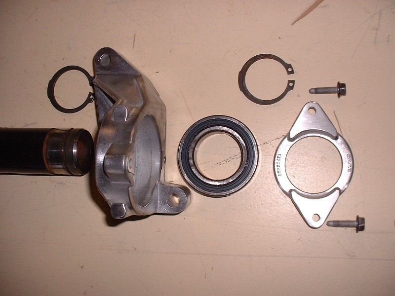
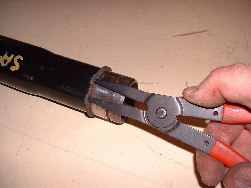
Here’s the 2007 Saturn Ion jackshaft cleaned up and disassembled. It’s really quite easy to take apart, all you need is a pair of good snap ring pliers and an arbor press to get the bearing out of the carrier, and the bearing off the axle. The bearing is located in the housing on the left hand side of the picture by an integral backstop machined into the housing. To keep the bearing from walking out of the housing on the right side, there’s a ring (the piece to the extreme right of the picutre) that bolts to the housing and sandwiches the bearing against the backstop. (Notice these are SAAB parts!)
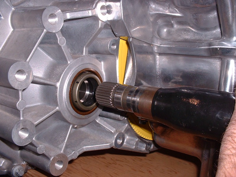
I needed to visualize where the jackshaft bearing would be located and what bosses on the engine might be available to hold it in place, since the Ion bearing housing wasn’t lining up with anything. I temporarily installed the jackshaft into the F40. Unlike the Fiero transmissions, there aren’t any snap rings that hold the jackshaft in the transmission, rather, this function is performed by the bearing housing.
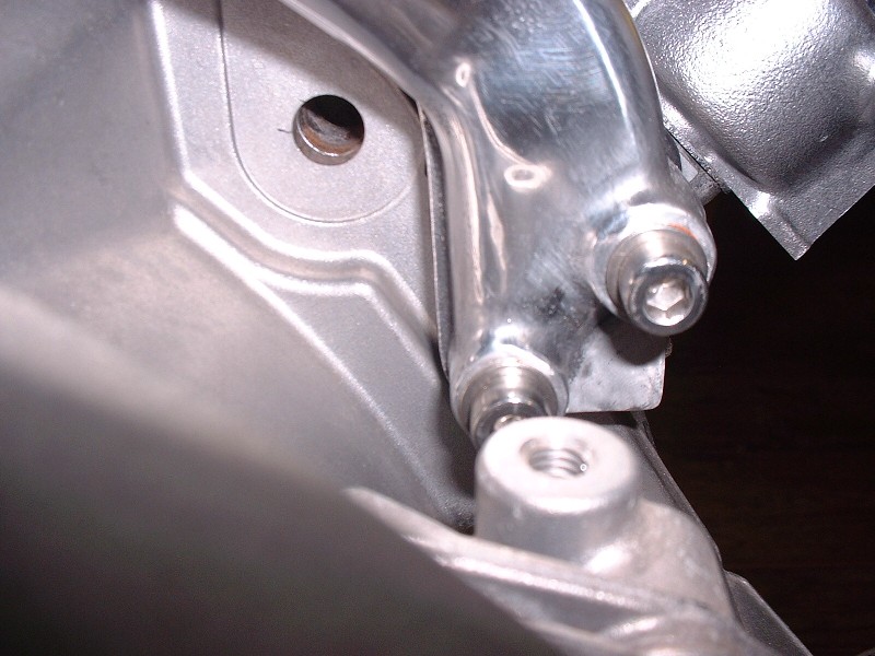
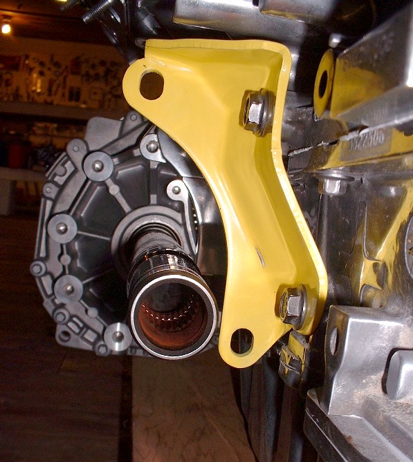
After lots of eyeballing, there just didn’t seem to be a good way to fabricate and mount a custom housing because the bearing fell too close to the bosses on the block to make good use of them. Then in a fluke, I installed the OEM automatic transmission bracket on the engine and the light went on.
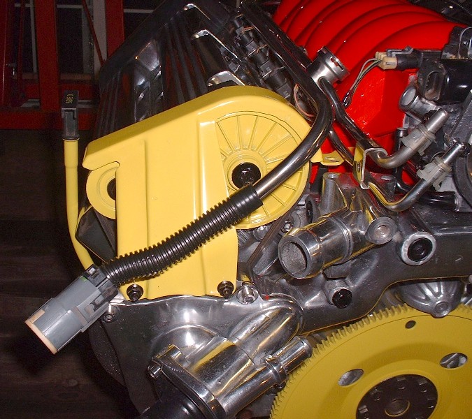
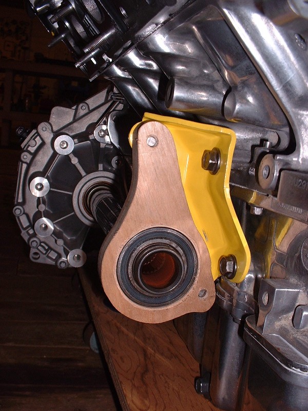
It still took a little figuring out, but the OEM bracket afforded a nice strong base from which to work with. It also placed the mounting holes for any new bearing housing design in a much more favorable orientation to work with. (BTW, the dullness of the block is due to me having sprayed it with WD40 to keep it from oxidizing.)
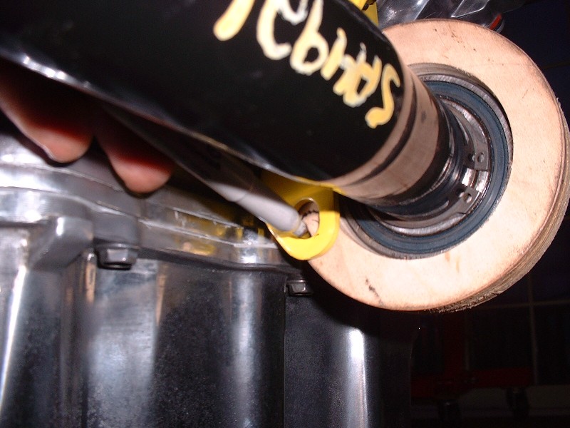
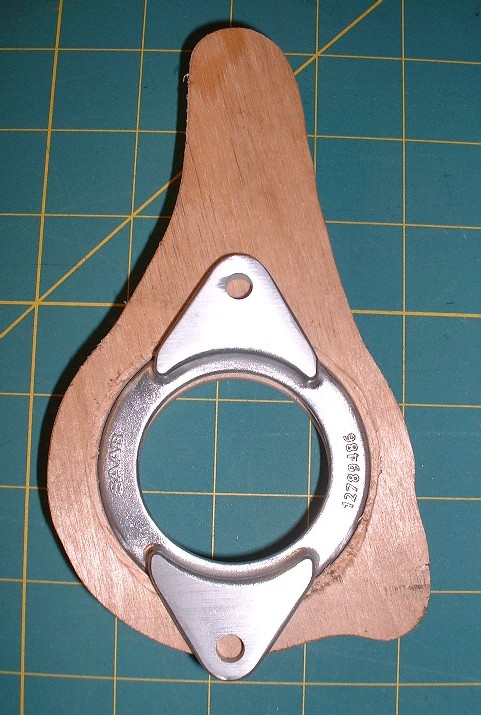
The next challenge was to find a way to measure the distance from the holes in the yellow bracket to the centerline of the of the axle in free space. After some thought, I fabricated a preliminary jig out of ¾” plywood that would hold the bearing and that I could then install on the axle. I cut the wooden jig to a 4-1/8” outside diameter because I happened to have a hole saw that big and because it left enough material to be able to pick up the lower hole on the yellow bracket, and still clear the block. It could have been any shape but the hole saw was handy.
To make sure I got the bearing at the right depth on the axle, I installed the inboard snap ring, and then pressed the bearing and preliminary jig into place.
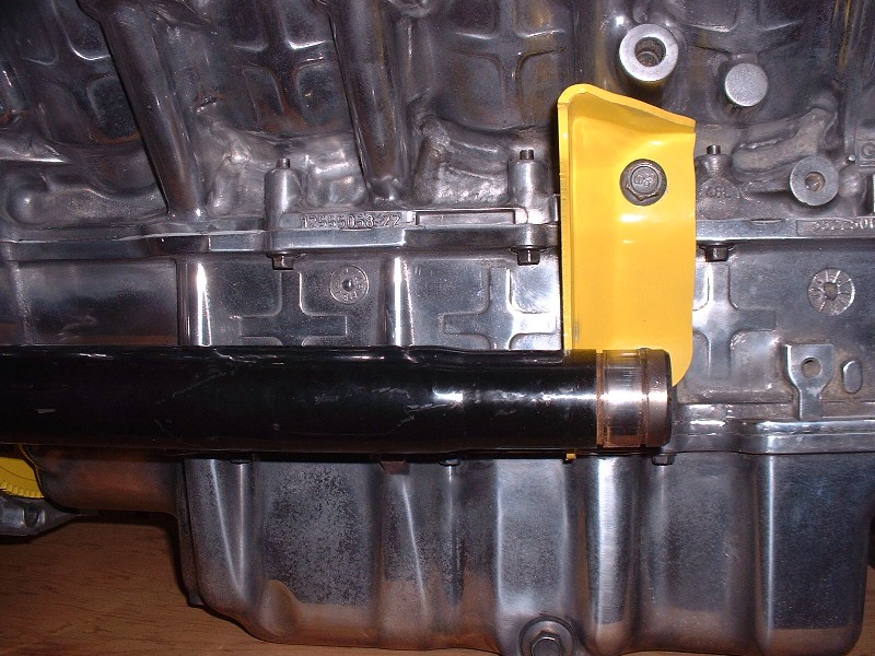
Once the jig was securely butted up against the yellow bracket, I double checked that the jackshaft was also inserted the proper depth into the transmission. To do this, I simply made sure the mark on the shaft from the original car's output seal was more or less in line with the F40's output seal. Then, I traced the location of the lower hole onto the jig from the back side of the yellow bracket.
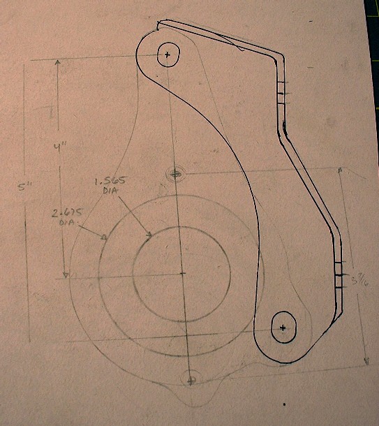
This then gave me a fairly precise ability to measure where the mounting hole was in relation to the center of the axle, and it allowed me to make a few measurements to determine how thick the final housing would have to be to reach the bracket on the inboard side, and yet still locate the bearing in the correct axial position on the jackshaft. With that information, I was able to work up a shape for a new bearing housing that would mate to the OEM transmission bracket. Here is the preliminary drawing I made.
If it helps, I found that using the stock fore/aft location on the cradle worked fine for mounting the N*. Not sure if you still have the ability to pull that from your setup or not.
Your IFG body will require a 3" stretch on your wheel base. The easiest way is to stretch the cradle and move the top of the struts back rather than cutting the car in half and rewelding it. The N* requires that you move the front crossbar on the cradle forward 3". I've never heard of it done but why not do the stretch on the cradle behind the front crossbar? That way you kill two birds with one stone. (If you like killing birds with stones) My AD355 body has the rear wheel wells moved forward 3" so that I maintain the stock wheel base. If I were doing it over I would use a stock wheelbase body and stretch the cradle instead. Like everybody says, WHAT A GORGEOUS DRIVETRAIN!!
i will say it looks beautiful so far. everyone i know asks me why my motor is still sitting in the garage andnot running in the car and its beacuse im also taking the time to make everything fit perfet for the best look possible. but your build surpasses mine by far.
Thanks for your comments kikinz24. I’m starting to feel the same way about my project… the completion date just keeps stretching out there on the horizon.
Speaking of stretching, Dratts, I realize that the wheelbase on my car has to be lengthened 3” to accommodate the body. In fact luckily for me, the previous owner already took care of that and did a remarkably nice job doing it too. Mine was stretched in the customary location just behind the cockpit. I’m not sure your idea of stretching the cradle would work. You would still need to move the strut towers back by an equal amount, which would defeat the purpose and make it a lot harder to do.
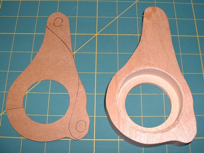
Anyways, I’ve got more pictures to share so here we go: Once I had drawn out the shape of the jackshaft bearing mount, I wanted to make one out of some scrap hardwood I had lying around to confirm the dimensions were accurate. I cut out the cardboard version and used it to trace the pattern on a 1” thick piece of wood. Then I used a pair of Forstner drill bits to cut the bearing recesses, and a band saw to cut the outside shape.
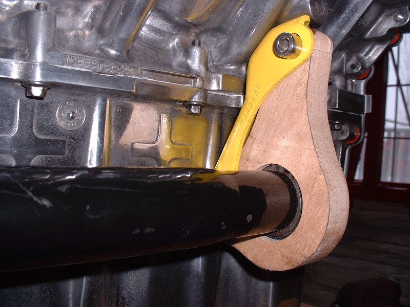
I used hardwood so I could drill and tap the mounting holes and actually use them. Then I pressed the bearing into the recess and then the jackshaft into the bearing, and finally test fitted the wooden mount to the engine bracket.
I’m glad I took the time to do this extra step because even though I could get the bearing mount to fit, it forced the axle to be raised an 1/8” higher at the bearing end than it was at the transmission end. By raising the mounting holes 1/8” on the final design, the axle would line up perfectly level.
Oh, and here’s another reason why it was a good idea… can anyone spot the problem?
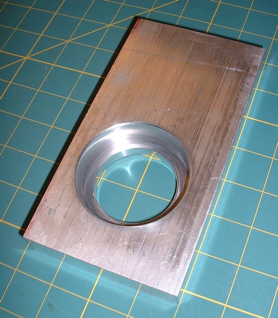
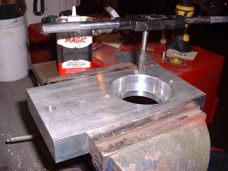
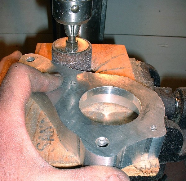
With the drawing finalized, I took a run out to my favorite machine shop where for $60 they sold me a 7” X 3.75” X 1” block of 6061-T6 aluminum, and machined the holes for the bearing. You gotta like that!
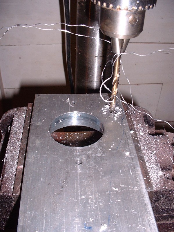
It was nice that there were some finely finished square edges on the block since that made locating the mounting holes a piece of cake. I double and triple-checked my measurements and decided it was time to make some aluminum shavings of my own. If you decide to make something like this yourself, make sure you use a drill press otherwise you’ll surely end up with holes that aren’t parallel.
Then I tapped the two sets of holes for metric threads since everything else on the engine and car would be metric. I tapped the mounting holes for M10 X 1.5 and the little bearing retainer holes for M6 X 1.0 if I recall correctly. I almost ran out of length for the smaller tap while trying to cut the threads all the way through the 1” material.
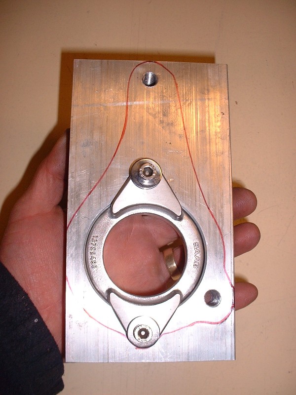
Once that was done, I transferred the final outline of the bearing mount onto the block of aluminum and test fit the bearing retainer just to make a prettier picture.
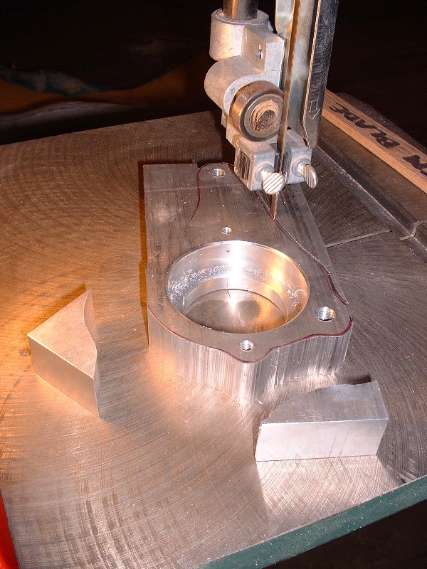
Then it was time for this thing to shed some weight! Unlike some of the richer people here on PFF with multi-axis computer numerically controlled milling machines, I had to resort to using my trusty-dusty band saw to make quick work out of getting the rough shape to come out. My machine shop asked how many I was going to make and offered to enter the design in Solidworks for a nominal fee, but I couldn't see a big market for it and besides, I wanted it, like now. As I cut through the solid block of aluminum, I started to feel a little like Michelangelo probably did as he was carving the statue of David out of marble, except I was probably more excited.
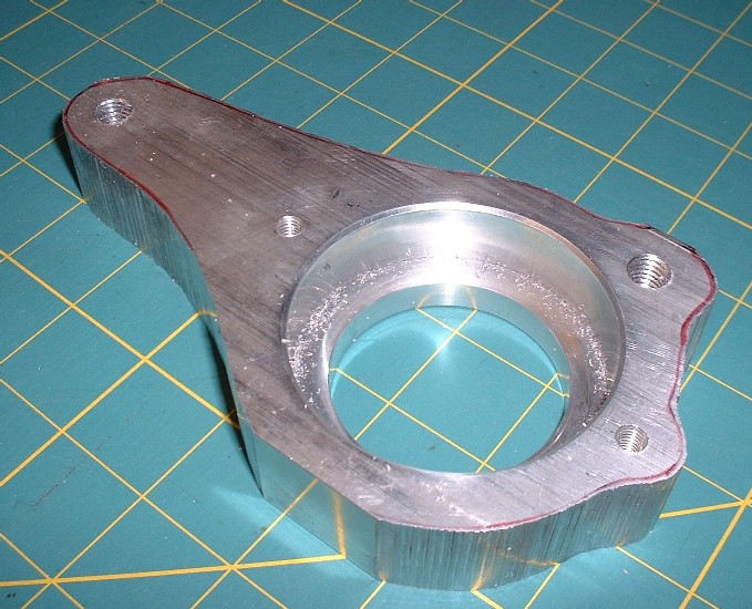
Here’s the rough cut bearing mount after surgery. It almost looks like a connecting rod… hmmmmm….
A few more operations to get rid of the scars and it wasn’t long before this thing started to look like it might actually belong on my engine. I used a 50 grit sanding drum initially on the edges, and then traded up for one with 100 grit. The drums lasted surprisingly long, in fact I only went through one of each.
I have not posted on this forum in a long time but I felt I had to. Excellent thread man! It makes me want to build another Northstar Fiero. I sold mine after I had most of the bugs worked out of the Big Stuff 3 ecu on a 2003 engine. I regret selling it and this thread has me on e-bay looking for an engine to build.
Thanks guys, I appreciate the feedback… it keeps me motivated! Hey Crzyone, it’s funny what comes around, goes around. You were one of the initial guys with your build thread that inspired me to build a Northstar! I poured over a lot of threads before deciding to take the plunge and yours was one of them.
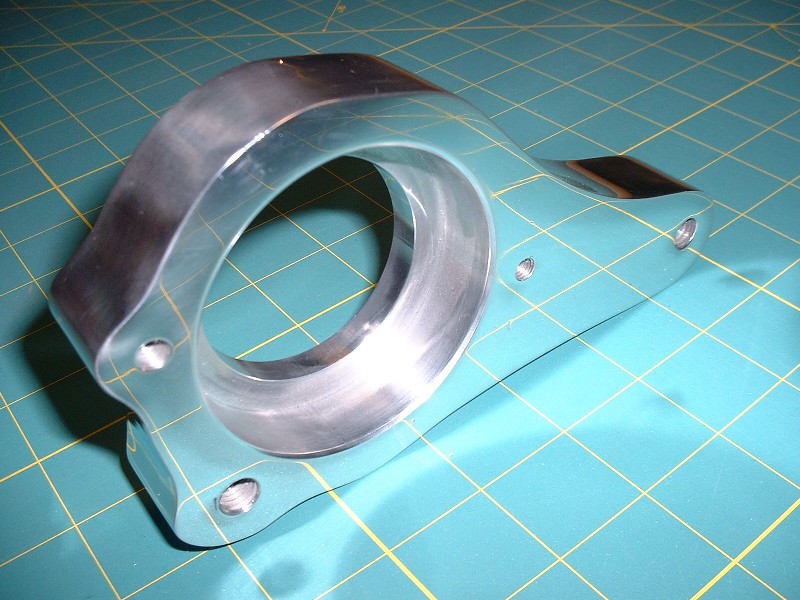
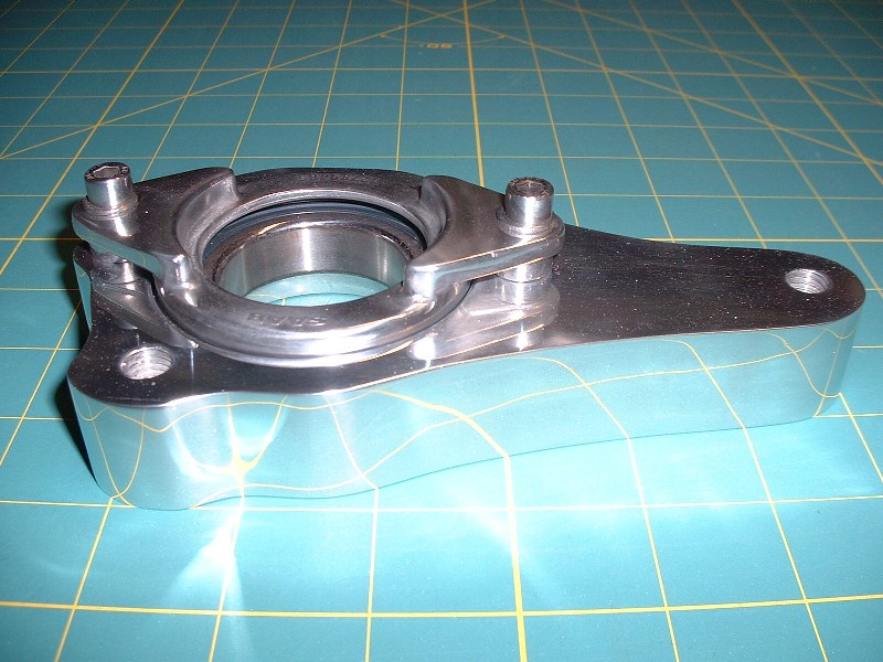
Back on track here… 6061 aluminum is amazing to polish, as I recently found out. I spent about two hours with some 220 grit followed up with some 320 grit and then hit the polisher with the bearing housing. I think I accidentally stumbled on Romulan cloaking technology! Check it out:
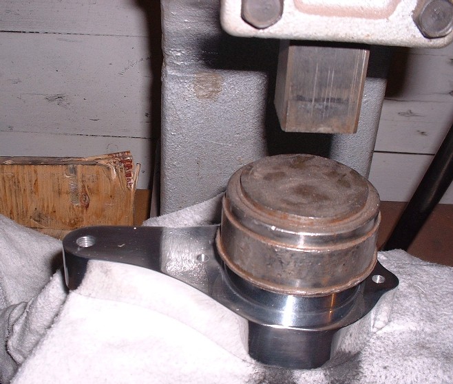
I didn’t want to get sanding and polishing grit in the bearing itself, so I did all the dirty work before pressing it into the housing. Here’s my faithful old arbor press squeezing that sucker into its new home. I apologize for the glare (then again, no I don’t!).
To craft the perfect bearing housing, I would have had to use an aluminum plate 1-3/16” thick. This would’ve given enough backspacing on the housing to mate up with the yellow bracket, and enough material on the front face of the housing for the bearing to be recessed ¼” into the front face. The ¼” is needed so that the countersunk bearing retainer sits correctly. Since the only available plate at the time was 1” thick I decided to make the housing full thickness on the back-side where it meets up with the yellow bracket, which meant that the front face would be 3/16” shallower than ideal. The only impact of having done this is that I’d need some 3/16” spacers for the bearing retainer, so I quickly fabricated some up from some spare 5/8” diameter aluminum rod I had laying around.
And since a picture says a thousand words, here’s where the spacers needed to go to make everything hunky-dorey. (I’ve only partly de-cloaked the housing so you can see what’s going on.)
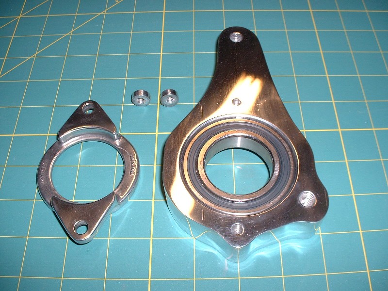
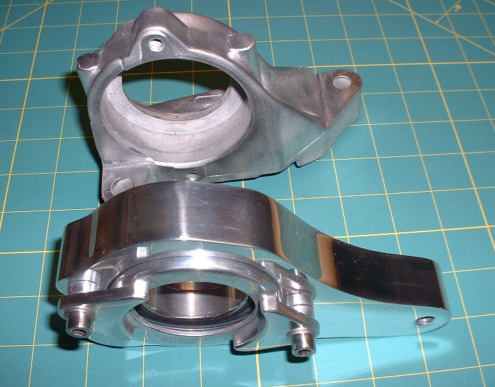
Here’s the old Saturn Ion bearing housing and my new one, side by side for comparison. I’m glad I didn’t bother trying to polish all the nooks and crannies on the Ion mount, I’d probably still be at it! It’s probably only made of white metal anyways and would have corroded within a couple months.
I roughened up the powder coating on the jackshaft with a Scotchbrite pad, undercoated it with some white paint, then hit it up with John Deere yellow. Once it was dry, I was able to press it into the bearing.
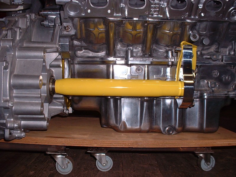
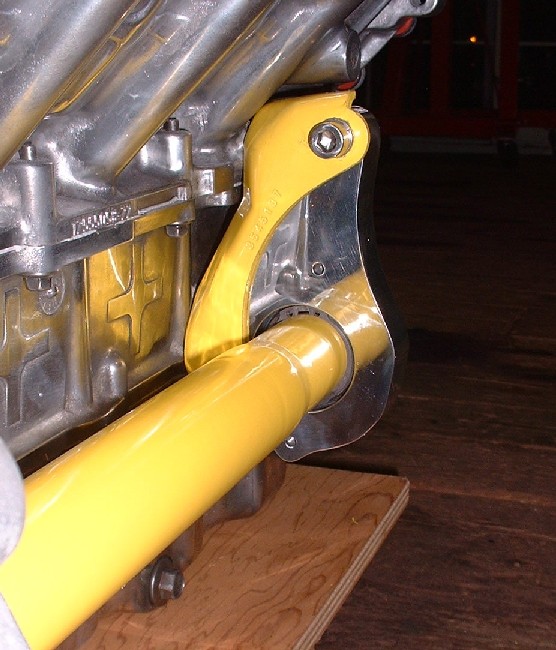
With done, all that was left was to install the assembly into the transmission and bolt it up to the old Caddy transmission snout bracket.
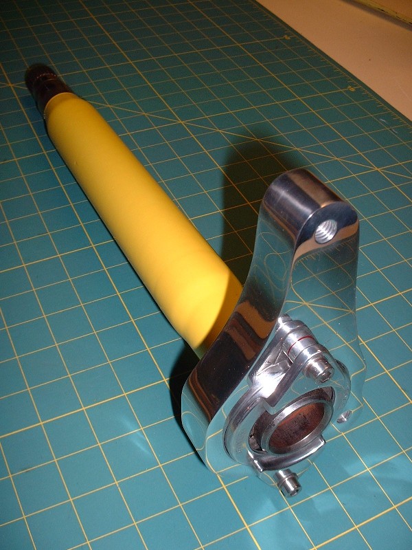
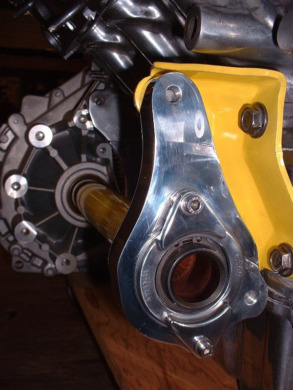
Initially, I found that the axle didn’t turn very freely, so I removed it and elongated the holes in the yellow bracket by about 1/8” closer towards the engine and tried it again. After a bit of adjustment up and down and sideways, I managed to find the sweet spot and tightened it up. In this shot, you can see why the through-hole in the back of the housing needs to be a certain diameter. It has to be large enough to insert a pair of snap ring pliers to remove the ring if necessary.
Finally, here’s the view from the wheel-side of things.
Now it’s time to get busy field-stripping the dilithium reactor, realigning the power tunnel, and fixing the impulse drive on the warp core. Geordi LaForge.... uhhh... I mean... Bloozberry out.