Somewhere back around page 12 or so I had originally considered using the lower hole in the knuckle for the upper control links, but it was impossible to make the roll center behave in that configuration. I played around a LOT trying to make it work exhausting a dozen or so ways to salvage the idea back then, but it just falls flat. I'm nearly certain that using the lower hole would mean major concessions in the kinematics.
Interesting. WAAAYYYY back in the day I developed a design for an SLA conversion for the '88 rear suspension. I lowered the cradle 1" from stock, so the lateral links pivots were 1" higher at the knuckle than the body. I put the outer pivot for the A-arm or lateral link between the knuckle and the brake rotor so that the setup would fit inside the stock 15" wheels. I positioned the inner pivot just outside the frame rail and MORE than 1" below the outer pivot. The design was extremely sensitive to the elevation of the inner pivot. However, by playing with that one variable, I was able to develop a system with PERFECT camber behavior, which also kept the roll center within a 4x6" rectangle through 5 degrees of body roll.
However, the roll center was in the range of 4-6" off the ground (don't remember right off) static. If you're looking for a roll center at the ground surface, you won't find a combo that gives you good camber performance.
However, the higher roll center works well in a Fiero, because it carries its rear end weight higher in the body than it carries its front end weight, especially with a DOHC engine. As the body experiences lateral g's, having the roll moment arms more equal front to rear helps ensure that the rate at which contact pressure rises is closer to the same front and rear. This goes a long way toward making the car neutral and the suspension easier to tune.
Reproduced to aid visualization.
quote
Originally posted by Bloozberry:
Also, the closer you can get your upper and lower links to the same length, the easier it will be to make the roll center location stable. It's not surprising that you have a hard time getting roll center stability, because your links are very different lengths. The upper and lower links in my design were much closer to the same length.
It also looks like your lower link inner pivots are higher than your lower link outer pivots... so you're "static ride height" as defined by suspension pickup locations is about 2" higher than mine was. Of course, it's relatively easy for you to lower your inner pivots without lowering your car.
[This message has been edited by Will (edited 09-07-2013).]
Originally posted by kennn: Does your latest proposal shorten the wheel base, or are you relocating the forward trailing link pivot to the rear to compensate for switching the uprights?
I kept the center of the wheel in the same location (no wheel base change) and moved all of the inboard upper and lower link mounts to compensate for the asymmetry of the knuckle.
quote
Originally posted by kennn: If I understand correctly, you wanted to maintain the stock length of the trailing links.
Not exactly... I bought HT Motorsports entire 6" rear track increase package (3" per side) which included the stretched lower lateral links (not using them), strut bottom adapters (not using them either), and trailing links that were longer and designed to compensate for the knuckle that was moved outboard, yet still pick up the stock inboard cradle mounting point. I'm planning to use these trailing links, not the stock ones. What I meant a few posts ago is that by swapping knuckles side to side, even though it would pull the trailing link further backwards, I wasn't planning to change the length of the HT trailing arms but rather compensate for the relocation by sliding the inboard mounting points back to meet up with the trailing arms.
quote
Originally posted by Will: WAAAYYYY back in the day I developed a design for an SLA conversion for the '88 rear suspension...the design was extremely sensitive to the elevation of the inner pivot.
I found that the roll center movement is extremely sensitive to the elevation of the inner upper pivots.
quote
Originally posted by Will: If you're looking for a roll center at the ground surface, you won't find a combo that gives you good camber performance...the higher roll center works well in a Fiero, because it carries its rear end weight higher in the body than it carries its front end weight, especially with a DOHC engine. As the body experiences lateral g's, having the roll moment arms more equal front to rear helps ensure that the rate at which contact pressure rises is closer to the same front and rear... I developed a design for an SLA conversion for the '88 rear suspension... the roll center was in the range of 4-6" off the ground (don't remember right off) static.
I wanted my roll axis sloped downwards towards the front for those very reasons, and achieved a front static roll center located 2.8" above the ground and the rear at 7.4".
quote
Originally posted by Will: I was able to develop a system with PERFECT camber behavior, which also kept the roll center within a 4x6" rectangle through 5 degrees of body roll.
My current design gives a 2" suspension drop over stock, and gives a 0.7:1 degree camber angle to body roll ratio through 6 degrees of body roll, which is what I aimed for. My rear roll center moves within a 1" tall X 15" wide box through 6 degrees of body roll... a far cry better than the stock '88 configuration at the taller stock ride height which allows the rear roll center to migrate through an 18.5" tall X 82.5" wide box through the same range. That box became significantly larger with the stock configuration on 2" lowering springs.
quote
Originally posted by Will: Also, the closer you can get your upper and lower links to the same length, the easier it will be to make the roll center location stable. It's not surprising that you have a hard time getting roll center stability, because your links are very different lengths.
Finding the sweet spot may be more difficult with larger differences in the link lengths, but now that I've found it, I believe my camber gain and roll center stability are pretty darn good. Did you ever make a thread showing your design? I can understand not wanting to divulge the details, but even a schematic would be interesting to look at.
[This message has been edited by Bloozberry (edited 09-07-2013).]
Originally posted by Bloozberry: My current design gives a 2" suspension drop over stock,
Your drawings show that the inner pivot of the lower lateral links is higher than the outer pivot. Since they're level stock, that does not reflect a drop.
Well, you can argue it any way you want... but from my perspective a combination of wheel, cradle, and suspension geometry changes resulted in a vertical wheel-to-fender gap change of 87 mm's. I've shown that progression in earlier parts of the thread with drawings.
For those that don't care to look at more graphs, but are interested in the impact of flipping the knuckles around just the same, the short and sweet of it is that the only parameter that changes is anti-squat. The static value at ride height doesn't change since I kept the same trailing link angle, but rather than anti-squat increasing as the suspension compresses, it decreases, probably as a result of the trailing link attachment point behind the centerline of the axle at the knuckle. It would be better if the anti-squat increased instead. The magnitude of the decrease is small enough that I am going to go ahead with swapping the knuckles side to side and carry on building up the suspension accordingly. For what it's worth, the stock '88 suspension also experiences a decrease in anti-squat in jounce as well.
On to the graphs for those that are more inclined to see the proof of the pudding. You'll note that the blue lines are stock Fiero performance, rust lines are my previous SLA design with the knuckles on the correct sides of the car, and the pink lines are the same SLA design with the knuckles swapped left to right (and minor modifications to account for the asymmetry of the knuckle). In most cases you can't even see the rust colored line because the pink line is directly on top of it, meaning there was no change between the original SLA design and the flipped knuckle design. Remember that these graphs represent the suspension's behaviour over a huge 6" total travel from full jounce to full rebound, and a crazy 12 degrees of body roll from full tilt left to full tilt right. I don't expect to allow that much movement but the large range shows the effectiveness of the design nevertheless.
I'll start with anti-squat since I've already summarized the results above.
You'll note in the graph above that both SLA designs appear to have significantly less than what the stock configuration has at ride height, but then I'm not entirely convinced that the Lotus software calculates anti-squat properly for a McPherson strut arrangement. Everything I've read says that in such a configuration, anti-squat is technically limited to a max of about 28% or so. Again, my understanding of how anti-squat is derived for different configurations is limited so I'll let others argue the point if they see fit. The important characteristic of this graph is that it shows by flipping the knuckle around, that anti-squat decreases with jounce. For best performance, it should increase or at least stay relatively constant, like the original SLA design did.
For all the remaining graphs there is virtually no difference between the flipped and non-flipped designs... but each offers better performance over stock.
And because the above graph isn't completely intuitive (at least for me) here's what the camber numbers mean at the full 6 degrees of body roll for the flipped knuckle design (the outside tire camber being much more important than the inside tire because of the weight transfer):
This gives me the green light to forge ahead with the flipped knuckle design, so once again, many thanks go to ccfiero350 for the brilliant idea, to Zac88GT for the use of his software, to Will for his sanity checks, and to everyone else for helping me brainstorm through this unexpected problem.
(Edit: reformat roll center to body roll graph)
[This message has been edited by Bloozberry (edited 09-07-2013).]
What's going on here? This doesn't make any sense. If your lateral and toe links are parallel and the same length, there shouldn't be any toe change with suspension travel. However, the graph shows way more toe change with suspension travel than stock.
[This message has been edited by Will (edited 09-07-2013).]
Hmm... That may be cross-coupling of camber and toe due to a "caster" change resulting from the knuckle tilting forward and aft due to the action of the short and long trailing arms.
Some people try to be fancy by setting the geometry up for toe-in on jounce and toe out on rebound to give the chassis turn-in understeer. I don't think that's a good idea; I think it's a bandaid for shortcomings elsewhere in the system.
I had the same issue with with the 17x11 rims and the strut being very snuggly.
One thing to consider, give yourself some options and make the anti squat adjustable with multiple front tie in points. Sometimes little or no anti-squat works best for a given track.
------------------ yellow 88 GT, not stock white 88 notchie, 4 banger
Thanks ccfiero350. Your suggestion for adjustable front tie-in points for the trailing link are a good idea, in fact I had already considered that in my drawings with several holes in the forward trailing link mount allowing the angle to be adjusted. I still plan to do that.
I spent what free time I had over the last couple days cutting the upper knuckle mounts out of 1/4" steel plate and shaping them so they look more-or-less "factory". To get the holes all perfectly lined up among all four plates I took lots of time to make sure the holes in the first one were bang on, then used that one as a template to drill the others. By clamping the first one onto the top of each successive one, the drill bit can't wander (as it so often does even with a pilot hole) because it sits in the well formed by the hole drilled in the top piece. After each hole is finished, I get rid of one pair of Vise-grips and replace it with a bolt through both pieces in the newly drilled hole to ensure the alignment stays true while drilling the other holes.
Once again I used my more detailed drawings to create the templates for all of these pieces at the top of the knuckle. The angled piece was carved out from 2" x 2" x 1/4" steel angle iron rather than two pieces welded or one piece bent since the angle iron is stronger than either alternative. Here are all the pieces:
After I bevelled the edges of the parts that make up the forward upper knuckle mount, they were ready for welding. This being a major structural part, I counted on my local professional shop to handle the welding. They welded along the outside edges and wrapped the welds around a half inch or so to the inside edges for additional strength.
With both pairs of upper knuckle mounts completed, I finally had a chance to mock up two upper links and the shock pushrod to the knuckle and check for clearances (disregard the washers centering the shock push rod... I have to mill down some proper spacers). For once my drawings didn't lie... everything fit as (newly) planned!
Here's a close up with all the links swung out of the way for a better view of the clearance between the suspension parts and the wheel rim. Although it's not really visible in this photo, there's actually still room to clear stick-on style tire weights if needed... I know because my other wheel has them right where it would create interference (of course).
Now I have to get back to the inboard mounts and move them to suit the flipped knuckles.
Thanks northeastfiero, yours is looking great too.
I've been busy over the last two weeks modifying the lower and upper link mounts for the flipped knuckles... and so far I've only managed to complete this work on the driver's side. It doesn't sound like much but I like doing things two, three, and sometimes even four times before getting it right! I started by cutting off version 1 of the lower link mounts from the cradle, measuring their new locations to accommodate the flipped knuckles, fabricating one new mounting ear because one ear of the forward mount now sits on the sloped part of the cradle rail, and tack welding it back all in place. All the mounts were moved a further 28 mm forward on the cradle. Here's the latest configuration, although I will probably weld a gusset or two to the new long ear in the foreground:
With the lower end completed (again), I started reworking the upper mounts attached to the top of the lower main frame rail. I had already made the upper mounts for the non-flipped knuckles, but they were no longer any good because flipping the knuckle meant they'd have to be moved roughly 65 mm further backwards on the rail. Since the rail's profile changes rather significantly in that area, the old mounts became useless. I also decided to take bubbajoe's advice and give the upper mounts a larger surface area to spread the loads onto the stock frame rail. Rather than welding the upper mounting ears directly to the rail's thinner metal, I decided to add a piece of 2" x 2" x 1/8" angled steel along an 18" stretch of the rail to anchor the mounting ears.
I then measured, cut, shaped, drilled, and tacked the four new upper mounting ears to the angle iron:
The forward mount sits at a 51 degree angle to the centerline of the car, but the frame rail also diverges from the car's centerline in that area by 7 degrees, so it took me a few tries before my cardboard templates actually fit properly with the hole at the right height, angle, depth, and lateral coordinates. It also took several attempts to make the metal mounts since they also needed correctly bevelled edges where they met the vertical parts of the rail, not to mention you need to measure twice and cut once. On one attempt, I managed to get a perfectly fitting part, then promptly drilled the hole 10 mm's lower than it should have been. Anyways, this is the view of the upper forward mount as seen from the engine bay looking outwards:
Here are all four mounts on the driver's side: upper, lower, fore, and aft, finally tacked in place and ready for some links:
The next step was to build up the links to the correct lengths. As I mentioned earlier, I like to do things several times before getting it right. In this case, I set about screwing the jam nuts on all the rod ends, then threading the rod ends into each of the swaged tubes. I had printed a legend to remind me how long each link needed to be eye-to-eye and immediately ran into a problem. It seems when I ordered my tubes, I had forgotten to take into account the length of the jam nuts so most of my tubes were too long. I could have cut them down, but I like to go by the rule of thumb that a rod end should be threaded into a swaged tube over a length equal to 1.5 times the diameter of the threads. Luckily I only needed to order six new tubes out of ten, adding a mere $100 more, and one additional week to the design (I've amended the list of parts I posted earlier to reflect these changes). So here they are... all ten links dialed in to the correct length and ready for installation:
I then simply attached the two upper and two lower links to their respective mounts on the frame using a 1/2" diameter fine threaded grade 8 bolt and a pair of rod ends spacers per mount. I made sure to buy bolts that were unthreaded along the length between the mounting ears, which for the most part, meant buying extra long bolts and cutting them down to fit correctly.
The knuckle, brakes, and tire mock ups are next... so stay tuned!
It might not be much of an issue for you since all but one of the links per side will be fixed length, but you may want to consider putting some flats on the toe link tubes so you can hold them with a wrench to tighten the jam nuts. I didn't do this when I installed mine, and ran into issues getting them tight enough, so when they were out again, I took a large nut, bored the center to fit over the tube and then tacked it to the tube.
So the knurling on the tubes didn't cut the biscuit eh? Somehow I'm not surprised, but I like your solution. Thanks for the tip!
I usually try to post pictures of actual progress rather than mocking stuff up to make it look like I'm further ahead than I really am, but this post is a different story. I just can't contain myself. With the four lateral links installed (at least temporarily while I double check other measurements) I couldn't help mocking up the rest of the suspension to see how it would look. If performance is king, then aesthetics is a queen, and I think this system is going to be a royal couple. But judge for yourselves...
First, I installed the knuckle to the lower links and then to the upper links:
Then I propped the knuckle up on blocks at ride height, added the shock push rod to the top of the knuckle (while holding the other end of the rod up with some baling wire), then finally threw on the trailing link even though I haven't made up the forward mounting bracket yet. This is how it looked:
View looking forward from above:
View looking aft from above
Side view looking aft
Rear view
View from inside engine bay looking out
Pretty sexy eh? I was on a roll so I installed the 12" C4 rotors for a snap shot:
Then added the rear wheel and tire combo for a peek into the future:
And checked clearances (and rear views!)
And stood back for an overall impression:
I like it. Now I'm really looking forward to building up the shock bell crank system and adding the coil overs.
Thanks RCR and ccfiero350. I can't answer your question firsthand yet ccfiero. With only the two parallel lateral links at the bottom, the knuckle is still free to twist at the lower end. I need to get the front end of the trailing link hooked up to make it behave.
PFF member northeastfiero jumped the gun and is further along with the fabrication of this design than I am though. He reported no binding over 6" of travel, though he may or may not have used the exact same coordinates as me since his rear frame is significantly different, and I changed my design to the flipped knuckle approach after he had already completed his in the original configuration. I believe he's flipped the knuckles on his now too but hasn't reported back whether he ran into any problems.
Thanks YF and jb1... it's always motivating to read comments from other people!
The next thing I decided to puzzle out was the mounting system for the bell crank. My earlier drawings are noticeably sketchy in this area because I hadn't quite figured out how I was going to go about it. It was very difficult to visualize the physical space constraints for the bell crank mount without a 3D model, so I waited until now to try to figure it out.
I played around a fair bit with different concepts but most designs only work well on the driver's side where there is a lot more empty space above and around the transmission than there is on the passenger side where the engine seems to occupy every square inch. Also, the mount has to stay clear of the wheel and tire and the control links as they move through the entire range of jounce and rebound, plus keep clear of the swinging bell crank and not interfere with the shock & spring either. I've come up with a plan that I think will work fine on both sides though... it involves a simple heavy-duty pillar rising up from the top of the lower frame rail and having the bell crank mount to the top of it. I used some corrugated cardboard to fabricate a 2" X 3" rectangular tube as a template/proof of concept. It was tricky to get the right shape where it intersects the frame rail because of the compound angles involved, but it worked out pretty good and I only used up about three hot glue sticks and two boxes worth of cardboard.
Then I made up a quickie cardboard bell crank and bolted it to the top of the pushrod. That allowed me to find and transfer the angle of the bell crank onto the top of the mount and trim it to the right angle and height.
Here's the view from the inside of the engine compartment looking out through where the old strut tower use to be:
Once I was satisfied with the fit, I transferred the measurements to a steel 2" x 3" x 1/8" rectangular tube and hacked away at it with the chop saw and the angle grinder until it mated snuggly with the frame rail. It'll get welded to the reinforcement I added to the top surface of the lower frame rail earlier on:
And again, the view from the engine bay looking out:
I admit it's robust and utilitarian looking, but once it's painted black it will blend into the background and the focus will be more on the arms and the flashy polished aluminum coil overs running fore and aft in the engine bay.
Are you thinking about adding some supports to help control deflection front/rear and side to side? That pivot will be loaded in both directions supporting the weight of the car. A single support on the outboard side going up and around the bell crank to the upper frame rail should do the trick in a relatively simple fashion.
Thanks Paul for your input. This is only the first stage of the mount fabrication... just locating the pivot point. The "tower" will need braces for fore and aft, and for inboard/outboard stabilization as you mentioned. The fore and aft braces will be simple I'll just run some small diameter tubing in line with, and under the shock and spring to connect the top of the "tower" to some additional braces I'm planning on the front firewall.
The transverse bracing is a bit trickier to package, so I'm still brainstorming different solutions. I'm not entirely sure I understand your proposal though.
Don't mount that pivot in single shear. I strongly suggest coming down from the upper frame rail with another tower to the outer face of the bell crank.
Thanks Will... I'm trying to come up with a solution for that as well but it's not as simple as it appears. Dropping another beam from the upper frame rail to the outboard side of the bell crank impedes the ability to either slide a pivot shaft in place and/or place a nut at the end of, say a welded pivot shaft, to pre-load the bearings. Triangulating an upper beam that drops down from the upper rail would also present a challenge.
I understand the need for the pivot shaft to be in double shear, it removes the bending forces from the shaft and it also serves as a fail-safe mechanism should the bearing come apart. I've got some so-so ideas to accomplish this but nothing strikes me as being ideal yet. I've just got to keep mocking up different configurations until I find something that works. I've been racking my brain for a couple days and I'm out of ideas at the moment so I'm going to give it a rest and start modifying the passenger side while the ideas stew.
[This message has been edited by Bloozberry (edited 10-06-2013).]
YEARS later... I come in for an update (when to the corvette side... currently building a 406cid) and its still as detailed and amazing as before(also this and fieroguru are the only reasons(extremely happy to see the forum is still doing awesome) I check in). im extremely impressed. Ill buy ;D
[This message has been edited by dhobbs84sc (edited 10-08-2013).]
Hey dhobbs, nice to hear from you. Thanks for the kind words. I'm sure whatever you're doing on the Corvette will be equally impressive.
For this update, I haven't got a lot to show except that I've completed the rear upper and lower link mounts and mocked up the suspension on the passenger side. I would have thought it would go a bit faster given my experience on the driver's side, but it didn't. Every mounting point still needed to be measured in relation to several reference points to locate it accurately, and then I found that the various templates I made for the driver's side wouldn't work on the passenger side. A combination of the factory manufacturing process, and the 3" frame stretch (done by the previous owner) created enough error that I needed to fabricate all new link mounts on the passenger side frame to account for the deviations. Nothing big, but a few millimeters here and there make a difference! Here's the mocked up passenger suspension... note that the forward trailing link mount isn't made yet, nor is the shock pushrod connected to anything either:
And now for a quick break from suspension-talk. I knew early on that I wanted to do something different than the stock Ferrari pop-up headlights since I've always found the reliability of these systems a bit hit and miss. None of the Fiero motors are getting any younger, and neither are pop-up motors from other cars for that matter too. Throw in the need to engineer new linkages and create new mounts that are stiff enough not to vibrate or jimmy on our bad Nova Scotia roads, and I just figured there had to be an easier and better looking solution.
I've been hunting on and off now for nearly two years trying to settle on a headlight assembly that would fit in the space I have, follow the contour of the fender, have a glass lens, look more modern preferably with a nice looking projector, but not look too froggy-like either. Lastly, I didn't want to break the bank buying some $800 apiece exotic car lights. It was a tall order and that's why it took so long for me to get the courage to order some up without knowing if they'd fit or look any good. They're not a radical choice by any means since lots of people have used these on Diablo kits and the like, but I think they will make a nice departure from the bland stock Ferrari pop ups on the F355. What do you think?
I always wondered if those would fit as they would be so much easier to fit rather than making and fitting the oem style. A little fit and finish and those will add to the look very nicely. I started building my own proctor style lights in the original holes but ended up getting the oem headlights I molded instead.
Thanks Don I had to design my own pushrod system for my Stinger (308 replica) headlight pods and was never very happy with them... the rods were over twice as long as the stock ones were, the headlight pods were further apart offsetting the rods from the motor lever, and the geometry meant that the stock lever stops couldn't be used. I just couldn't make the system as play-free as stock, and that's the same conundrum I would be facing with the F355. I hope yours work out better... perhaps you'll share your system design so I can retrofit it into my 308 some day.
Back to suspension stuff! I decided to let the shock absorber bell crank mount stew some more and work on the trailing link mounts instead. In reality, I should have started with the trailing link mounts before the bell crank anyway, because until they are done, the location of the knuckles isn't pinned down in three dimensions, making it harder to get precise measurements for the bell crank location. As per my earlier drawings, I knew I wanted to attach the trailing link mounts to the lower frame rail, unlike the Fiero which has them attached to the cradle. My reason for doing it this way was because the new cradle and lowered suspension resulted in the trailing links being closer to the lower frame rail than the cradle.
Still, the biggest challenge is that the underside of the lower frame rail is curved, and the sides also change angles right where I need to locate the trailing link mounts. Laser level to the rescue! With some fooling around, I was finally able to come up with a two-part template that is feasible from a fabrication and installation stand point, and should rigidly hold the trailing link in place. Here's what the template for the driver's side looks like (disregard the lightening holes... I'm still debating whether I will add them or not):
It will fit on the lower frame rail just behind the cabin, like this:
The outboard side of the mount will be welded to the underside of the frame rail, which you can't see at the moment because the stock spot-welding flange on the frame rail obscures the view. Then, the inboard side of the mount will get welded to the inboard wall of the frame rail along the top, and the bottom will be welded to the top of the chassis cradle mounting flange like this:
Finally, the two halves of the mount will be welded to each other along their bottom edges. Once I knew what the pieces needed to look like, I cut them out of 3/16" steel plate leaving extra material wherever I knew I would need to leave it to give me the leverage to bend them:
Here's the second of two bends being made to the inboard plate in my 12 ton hydraulic press.
Here are inboard and outboard halves of one trailing link mount, fresh out of the press:
The extra material left in place for the bending process will get trimmed off now, but not before a final tweak to get the angles just right. The nature of steel is such that to get a 90 degree bend, you need to bend it past 90 degrees since it will always spring back a few degrees. Since my bender was made with 90 degree materials, the parts end up somewhere around 95 degrees once removed. I found that getting that last 5 degrees or so wasn't going to be easy with the 3/16" thick plate and the tools I had, so I dropped the parts off at the local welding shop for them to bend them that last little bit.
[This message has been edited by Bloozberry (edited 10-23-2013).]
As things seem to go with this project, getting the trailing link mounts lined up and welded in place was much easier said than done. The first thing I realized is that there simply wasn't enough working space between the bottom of the lower frame rail and the top of the cradle while the cradle was still in place. Then there was the issue of play in the location of the knuckle because of mismatched metric bolts in SAE holes in a few spots, and vice versa. To get the trailing link mounts accurately located, I first had to address these problems.
That meant removing all the suspension parts from the cradle, then pulling the cradle out to give me room to work. Once that was done I got busy with the wire wheel on the angle grinder and took the lower frame rails down to bare metal. I had marked the approximate location of the trailing link mount so I was then able to fine tune the shapes of the mounts to the frame rails. Once done, I tacked the outer half of the mount in place to provide myself with a starting point. (The lower square tube in the photo is the front cradle mount that was extended 3" further backwards to accommodate the chassis stretch):
Here's how the inboard half of the trailing link mount will be installed. It's bent along the top to meet up with the side wall of the frame rail, and at the bottom it will be welded to the extended cradle mount:
And here's a shot from the rear showing how the two pieces form a box with the frame rail forming the top of the box:
Now onto those pesky little details. The '88 rear knuckles have 12 mm diameter holes in the bottom to mount the lower lateral links to the knuckle. These are the holes that are notorious for "egging out" slightly and making a little slop in the toe of the wheel. My car didn't have enough miles on it to have worn the holes out of round, but I got them reamed out to 1/2" diameter to suit the 1/2" bolt I wanted to run through the hole in order to properly fit the 1/2" dia rod ends I bought for the new lateral links (phew!). I didn't trust any of the equipment in my shop to bore the hole straight through so I took both knuckles to my trusted local machine shop where they did them on a mill:
Now that a 1/2 bolt fits through the hole, that should take the play out of the bottom end.
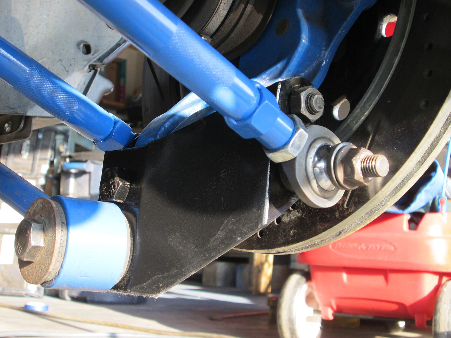
The next thing was to address the much larger amount of play at the top of the knuckle. If you recall, the holes in the top of the knuckle (that used to hold the strut) are made for 16 mm diameter bolts, however in my design the top bolt is replaced by a 1/2" diameter bolt. I wanted to make a sleeve to ensure there would be little room for any slippage. Rather than making a simple concentric sleeve though, I decided to make an offset one that would allow me to retain some camber adjustment without lengthening or shortening the links. I started out by cutting the threaded portion off an M16 grade 10.9 bolt, and drilling successively larger diameter holes axially through the shank:
Then, once I reached the 1/2" diameter I was looking for, I cut the head off the bolt leaving me with an offset sleeve:
The sleeve can now be mounted in one of two ways, either with the offset towards the center of the car for less camber, or towards the outside for more camber. One thing for sure, the knuckle won't flop around that top bolt anymore:
Lastly, since I was at the machine shop for the knuckles anyway, I brought four rod end spacers along with me that needed to be shaved down from 0.500" to 0.370" in length... (some day I'll get a lathe.) These are the spacers that are used at the lower end of the shock absorber push rod.
I finished getting both trailing link mounts fabbed up and managed to get the outer halves tacked in their precise location after much testing and measuring. I want to leave the final welding to the pros, so I'm not tacking the inner halves in place otherwise they'll get in the way of welding the outer halves. Nevertheless, I was able to clamp the inners in place tight enough to rebuild the suspension and check the alignment side to side. Since the trailing link was the last of the five links on each side, adding it secured the location of both hubs in three dimensions. Out of curiosity I ran a long straight-edge through the center of both hubs and double checked that the axes of the wheels lined up and were concentric, and much to my relief, they were perfect. Here's the driver's side built back up with the trailing link in place (less the shock and bell crank system):
Next up was to cycle the suspension up and down through it's range of travel to see if there were any problems with binding or clearance issues, and to do a rough camber check. To do that, I left the back end of the car raised up quite high so I could cycle the suspension in rebound, and then set the wheel on top of a hydraulic floor jack. I pumped the jack up until suspension was at ride height, relative to the frame, which I could determine by matching the angle of the lateral inks to the angle they would be at if the car were on the ground:
Measuring the clearance between the top of the tire and the underside of the upper frame rail gave 2.25". Disregard the lower hanging weld flange at the back of the rail because it doesn't interfere with the tire.
This next shot isn't the greatest but what I was trying to capture is that the wheel at ride height is currently vertical (ie no camber). I will add -1 degree of camber to the suspension when I finalize the alignment.
To measure the camber, I used a long straight edge across the tire side walls and an angle finder. You can't see the angle finder's scale because of the camera flash glare so you'll have to trust me. The angle finder is really easy to use, it has a bubble level on one side that rotates along with the center section of the dial, so all you do is set the finder on a straight edge, rotate the center dial until the bubble is centered, then read the angle on the dial from a stationary pointer.
Next, I pumped up the jack to give max jounce which is where the tire contacts the underside of the upper frame rail:
There were no binding or clearance issues with the suspension arms whatsoever. At 2.25" of jounce, I measured the camber change at about -2.5 degrees which is exactly where it should be according to my earlier camber vs jounce graph (note that the graph shows about -3.5 degrees at 50 mm (2") of jounce, however the static camber is -1 degree on the graph, whereas here I'm starting with zero static camber.) You can easily see the negative camber in the photo though:
Next, I lowered the wheel into 2.25" of rebound, keeping the lower end of the travel the same as the upper limit for comparison's sake. In this photo, there is 5.5" of clearance between the top of the tire and the underside of the upper frame rail:
Once again, the camber change is clear from the rear view, and once again it was what the Lotus software projected: +1.5 degrees
For those interested, I did cycle the suspension without the wheel on the hub through a huge range of travel to see what the physical limits would be. I didn't measure the actual jounce or rebound at each limit so I'll post that info the next time around.
With that cleared up, I can now focus on the bell crank mount design. My perspective changed by being able to sit in the empty engine bay so I've got some better ideas now how I'm going to tackle it. I also noticed that the rust bug had taken it's toll on the inner wall of the upper frame rail where the strut tower used to be. The driver's side is worse (first pic), but I'll need to address both sides as part of the bell crank mount solution.
Blooz, have you given any thought to backhalfing the frame, something along the lines of what I did in the back of this project? https://www.fiero.nl/forum/Forum1/HTML/086876.html you have put so much effort in to this that it just seems a shame to see the remnants of the Fiero chassis when you open the hood.
Thanks for your input there motoracer. The thought has crossed my mind, but it would be a substantial amount of work at this stage. You have to keep in mind that when I started out, my goal was to create a conversion that would be much simpler for the average joe with a few fabrication skills and tools to replicate. It's morphed away from that basic idea but it's too late for me to change course now. Too much time and effort have gone into accurately locating the suspension mounts for me to want to start that process over again. The time to have done what you suggest would have been when the frame was cut in half and before it was welded back together again with the 3" stretch. Even then, I would still need major structures at most of the same locations as the stock Fiero rear frame.
As for appearances, I'm pretty confident that once I've finished trimming up the remnants of the strut towers and the side walls, that it will be unrecognizable as a Fiero engine bay. The N* engine framed at either end by longitudinal coilovers will draw all but the most discerning people's attention away from whatever sheet metal is left.
hears an idea, since the vast majority of your work connects to the lower frame rail, leave it and do the upper, Helm used to have a fabricated piece that did the same thing.
Thanks for the ideas Joe, it would make good sense if I weren't so enthusiastic about moving onto other parts of the car at this stage. Once I gained access to the insides of the upper frame rail, I could see that the rustiness was limited to the area right around the strut tower, and except for the inside wall which I cut away, the rest was only surface rust. Replacing the entire upper frame rail just doesn't seem like it would pay off. Here's how it looked after localized sandblasting and priming:
I'll replace the inner wall of the rail as an integral part of the shock bell crank mounting system.
As for what the suspension links look like (without the tires obscuring the view) here are a couple pics showing them at various states of compression. First up is at ride height:
Next is at 3" of rebound. To note, there were no issues of clearance or binding at this point, although the trailing link bushing started to twist in it's mounts (as it's supposed to do) when I got to around 3.5" of rebound.
Lastly, this is what the links look like at 3.25" of jounce. I purposely moved them beyond the design limit of 3" to see at what point the system would bind or interfere with itself:
At 3.25" the mounts were still very free to move (no binding), except that the forward lower lateral link comes into contact with the trailing link. This is the view from the front looking back:
Way before this happens though, the tire touches the underside of the upper frame rail at 2.25" of travel so I shouldn't need to worry about this problem.
It all looks great Blooz. Very clean and well thoughtout. As I don't have alot of suspension experience, is it necessary to put in some sort of travel limitation to prevent the tire from contacting the chassis/ body? I've driven your road and 2.25" of travel is not that unrealistic.
What... you don't like the way the municipality maintains my road? We pay extra to have a team of six guys to come twice a year to fill the pot holes. One to drive the dump truck, one to shovel the asphalt, another to flatten it with his pickup truck tires, and three supervisors.
I'll definitely put in some kind of bump stop. There are a few spots where I could place one including on the chrome-moly shaft of the shock, or on the bell crank mechanism. Perhaps there are other/better locations as well but those two come to mind right away.


 Did you ever make a thread showing your design? I can understand not wanting to divulge the details, but even a schematic would be interesting to look at.


 Anyways, this is the view of the upper forward mount as seen from the engine bay looking outwards: