Looking good, nice to see some progress on the project. You have more guts (and money) than I do to rebuild a Northstar. Seeing how complex it is makes me wonder if I should have went with a 3800, I'll feel different when my swap is done. Did you consider a set of CHRFabs cams? I believe that they are only about $500 for a set. Beats $700 a piece and it's an upgrade, but I will be interested in how your refurbished cams hold up. Edit: Hooray! I own my first page ever!
------------------ * 97 Olds Cutlass DD * 86 Mustang SVO Rear Ended, R.I.P (Sold) * 86 Fiero GT, Soon to be Northstar
[This message has been edited by 17Car (edited 06-02-2010).]
Thanks for the comments Will, Erik, DoubleC, and 17Car. It's always more encouraging to continue the thread when you get a little feedback!
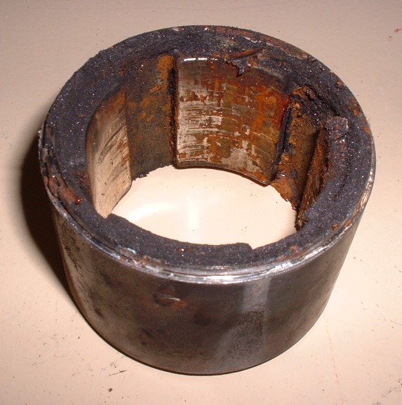
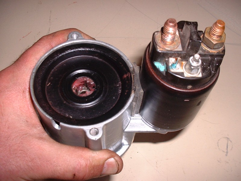
So for tonight's show, the next step was to clean up the magnet housing… here’s what it looked like before. It’s interesting to note that the magnets are fully sealed in a metal casing. Not sure why, but it’s a notch above the rest, as far as field magnets go. I wire wheeled the outside on my bench grinder and used steel wool on the inside to clean up the rusty stains. Then I spent ten minutes getting the wire wheel bristles that broke off and the steel wool lint off the magnets! With the power of these magnets, I could probably have used the wire wheel without wearing goggles!
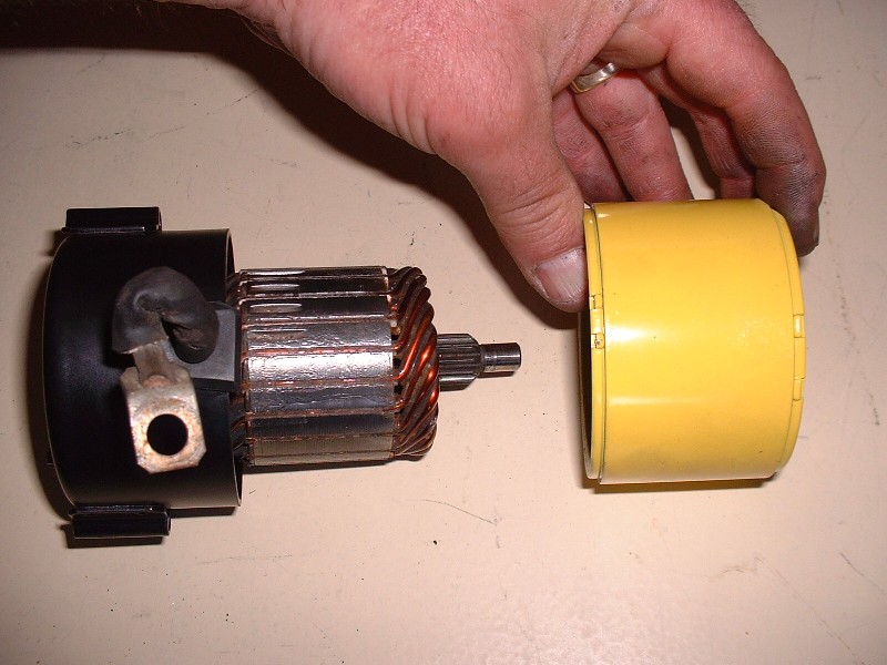
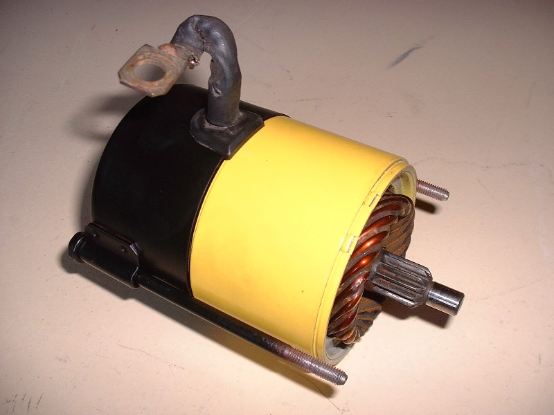
Once it was cleaned up and painted to match what I expect to be the body color of the car (at this point anyways), I was able to install it on the armature assembly. Two things: 1. nobody except me and whoever reads this post will ever know that it was painted to match the car, but what can I say… it makes for a pretty picture…
And 2. I learned the hard way that you simply can’t slide the magnet housing towards the armature and expect the armature to stay put. About two seconds after the above photo was taken, the armature whipped out of the brushes and stuck itself to the magnet housing. Of course that meant starting all over again removing the brush assembly and retracting them to be able to slip in the commutator again. But I’m a quick learner so the next time I went to install the magnet housing, I held the armature firmly in place so it wouldn’t get sucked out of the brushes housing.
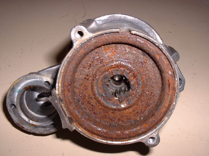
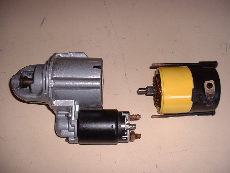
On to the gearbox half of the starter: The gearbox is separated from the motor with a plate that’s supposed to keep the grease off the motor. Mine was kinda rusty looking so I took it off and sandblasted and refinished it. Here’s what it looked like with the motor half removed.
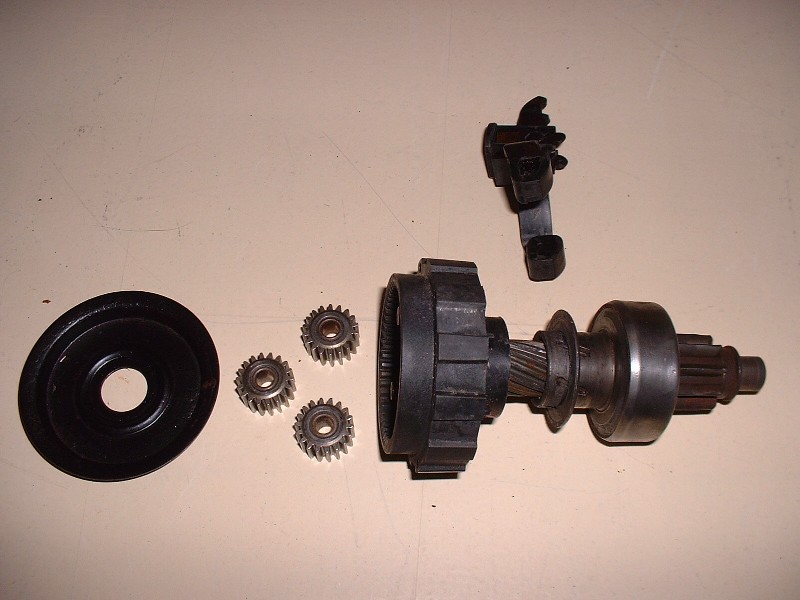
With the cover removed (it’s just held in place by a tab), you can pull three little planetary gears out, and retract the entire gearbox’s guts from the housing with a little persuasion. In this case, the sun gear is part of the armature shaft, which meshes with the three sun gears that spin on pegs that are welded to gearbox’s input shaft. This gears down the RPM of the motor and multiplies the output torque. The gearbox stator is kept from moving by having big plastic teeth or splines that engage the ID of the housing. That’s the part that needs a little coaxing to get the guts out. The other major assembly in the gearbox is the solenoid fork which acts just like a clutch fork. Here’s what the major parts look like once cleaned up:
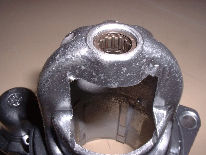
With the innards removed, I was able to examine the needle bearing in the starter snout and decided it needed to be cleaned and re-greased. I used varsol to desolve to old grease and spun it dry with shop air then used a Q-Tip to re-grease the needles. Here’s a close-up of the little guy after I cleaned it but before I decided to remove it and grease it properly.
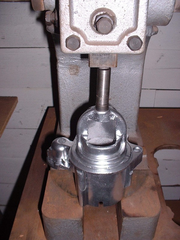
To remove and reinstall it, I used a small arbor press which made things easy, but I'm sure you could used a punch and hammer judiciously. In this picture I’m pressing it back in after cleaning and re-lubing it.
I promise to wrap up the starter rebuild in the next post, so for those of you itching for me to get back to the engine, the suffering is almost over!
Thanks Fierogt28. I had one of my customers tell me one day that "cleanliness is next to Godliness when it comes to building engines" and that sort of stuck with me. It's all about perceptions. It's also so much more satisfying to go to a car show and pop your decklid to a clean engine bay. Sure it takes alot more time but I think it's worth it. By the way, what's up with the line "even if it's going into a Fiero"? No disparaging remarks about Fieros are allowed here!
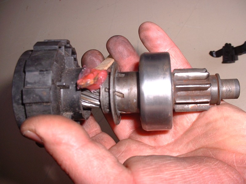
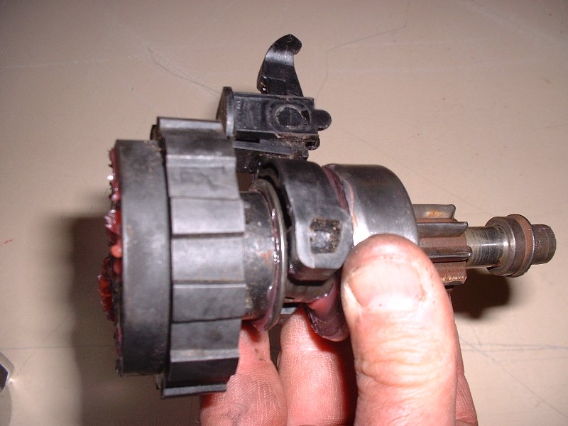
Anyways... cleaning and re-greasing the gearbox was pretty straightforward. The main component of the gearbox is the starter pinion assembly. The big black plastic part, as mentioned earlier, is locked to the gearbox housing but the portion in the right hand side of this picture is the part that whips out and engages the flywheel. Here I’m greasing the splines that the pinion travels on. The manufacturers of different car maintenance products are starting to get wise… make things like grease in pretty colors and even the women might take an interest in auto repair! (...apologies to the women of PFF)
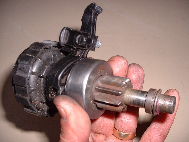
Next I greased up the backside of the pinion bearing that the actuating fork contacts, and installed the fork. The fork doesn’t stay there on it’s own, it has a little yoke that gets captured by the gearbox housing once it all gets put back together.
I greased up the pinion journal that will marry up with the needle bearing in the gearbox snout too.
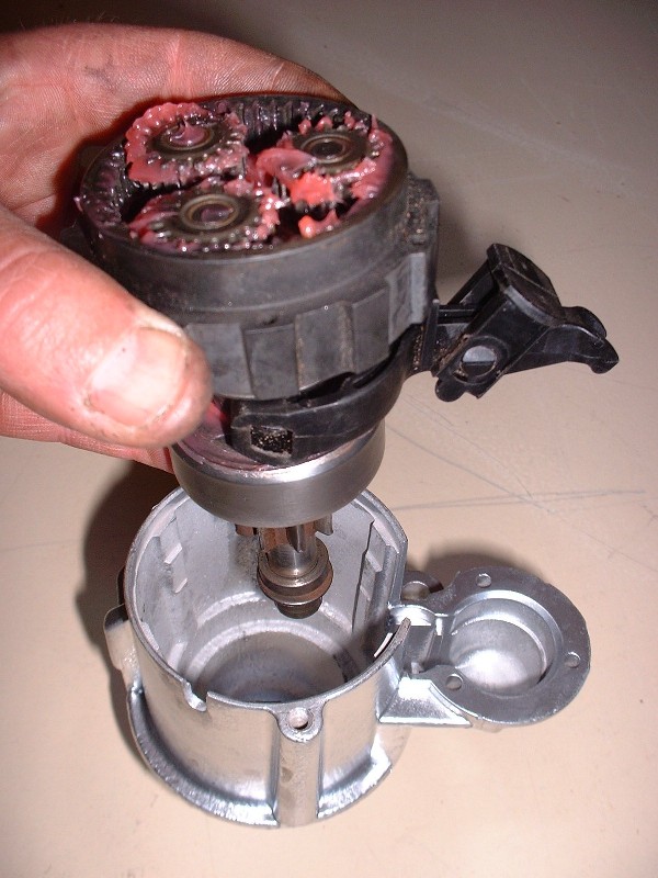
Then installed the three little planetary gears in the plastic housing and lubed them up good. At this point the pinion assembly was ready to be installed back into the gearbox housing.
It took a little persuasion to get the black plastic planetary gear housing to seat properly, and once it was into place, I realized why. The little yoke that the fork pivots on was binding up so I had to pull it all out again and take a little more care in aligning the yoke into it’s recess. If you take one of these apart, make sure before you close it all up that the little lever that the solenoid is connected to can actually pivot freely to slide the pinion gear back and forth.
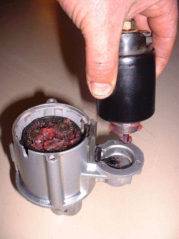
A little grease on the solenoid pushrod and it was installed using three little screws…
… then the gearbox grease shield…
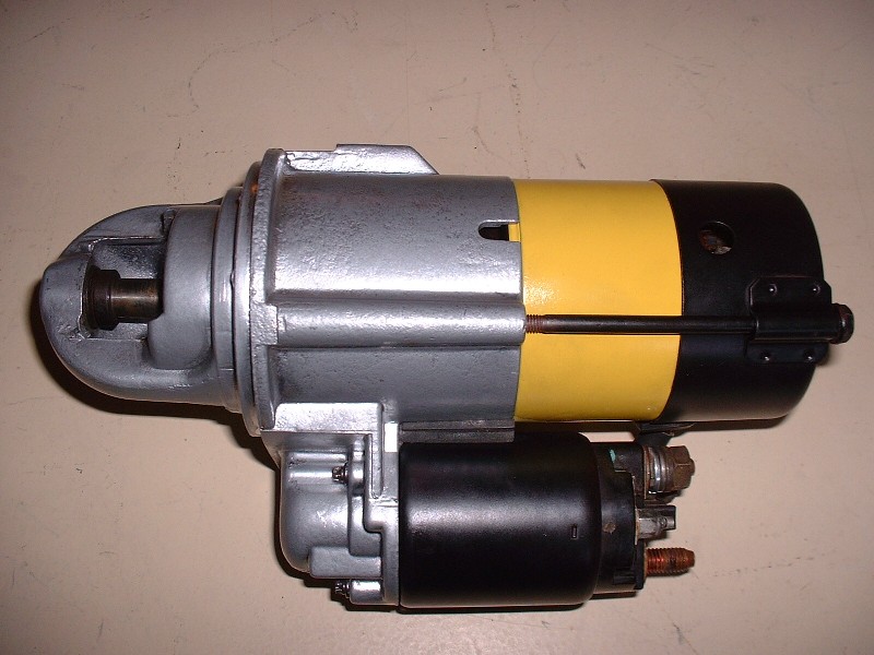
… and finally the starter gearbox was ready to be mated to the starter motor.
Ta-dah! One rebuilt Northstar starter. Tiny little bumble-bee-of-a-thing eh? I hooked it up to a spare shop battery and made sure it worked by cycling it about twenty times… I don’t want to have to deal with it again for a very long time.
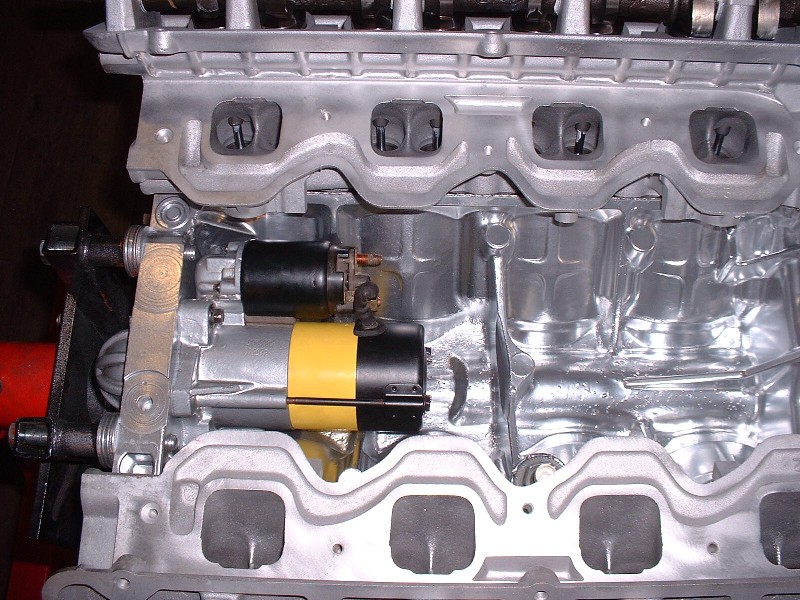
Finally, here it is mounted in place in the cylinder valley. The cables for it and the knock sensor run under the intake manifold and emerge up near the pulley end of the engine (oops, I almost said “front end of the engine”).
Blooze, what I meant was 99% of the folks that I see that own a fiero don't have a clean engine bay. They probably don't care because they aren't worth much; but that's to them. If anything, I want cleanness and new components through-out. I don't like doing a half ass job. But what your doing is exactly what I'd want, or do.
I'd like to see the car once your done. Sounds like an interesting swap and the 6-speed mated to it.
... haven't a clue... although the engine came from a big wreckers yard in Ontario called Schram's Auto Recycling (... rhymes with Scam...) and may have been pulled from the donor car a long time ago and sat outside. It's one thing to be stored outside under a hood and quite another to be left open to the rain and snow. But I'm just speculating. But Dratts, you live in California... isn't there a song about how it never rains over there? And I bet the only salt you've ever seen is next to the pepper!
That would be my guess too. Again thanks for all the info and pictures. Are you keeping track of the cost of your engine rebuild? I'm pretty much not in Ca. anymore. I still have an island by Antioch, but I spend most of my time in Coeur d' alene Idaho with my Murciealago replica. The N* 355 isn't getting as much of my attention until I finish the Murci. The Murci is registered and draws a ton of attention when I drive it, but needs a lot of work.
Mercy me... a Murci? Have you posted images of it here yet on PFF? What's it got for an engine? As for total engine costs I keep a detailed record of all my expenses to help the insurance appraiser come up with a replacement value for the car, should the need ever arise. The engine, engine parts, and machining to date (not including flywheel, and PCM tune) have cost me about $5150. Really not bad at all.
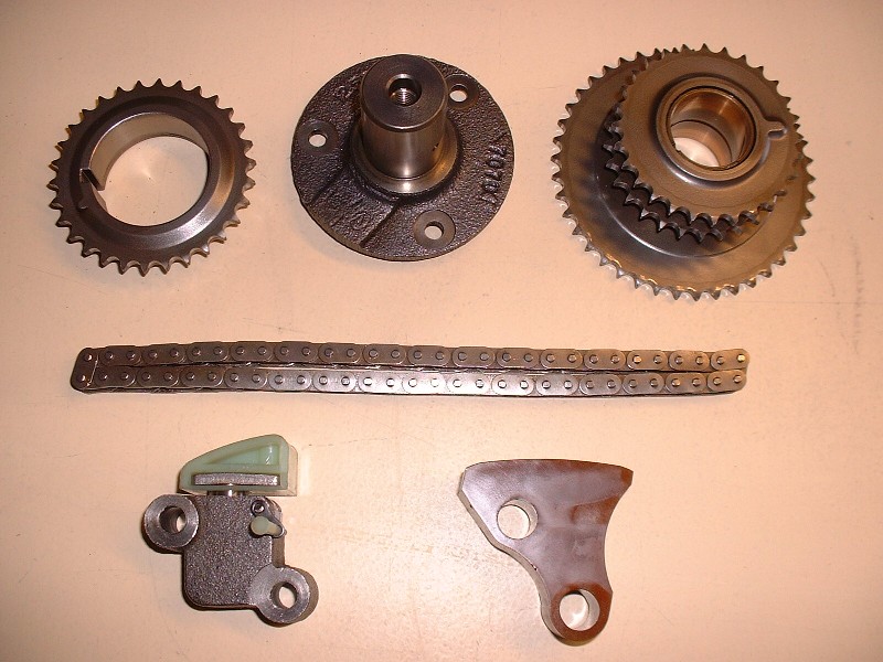
OK, so with the starter out of the way, I moved on to the valve timing components. It was a lot more intimidating and time consuming to read through the process than it was actually doing it. Once all the parts were cleaned up and inspected, I opted to keep all of the original timing components except the primary chain tensioner. If you've been following from the beginning, you'll remember why. So here now are the components that form the primary timing chain assembly from top left to bottom right: crank sprocket, intermediate sprocket set journal assembly, intermediate sprocket set, chain, tensioner, and guide.
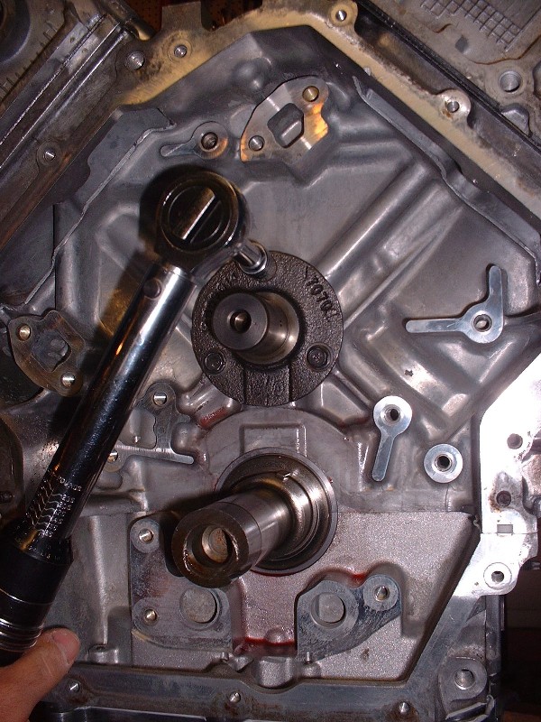
The first step is bolting on the intermediate sprocket journal assembly. It’s a no-brainer. Interestingly though, it gets fed pressurized oil from a hole in the back-side, and directs the oil to the sprocket set via rifle-drilled holes in the journal surface. Three bolts hold it in place.
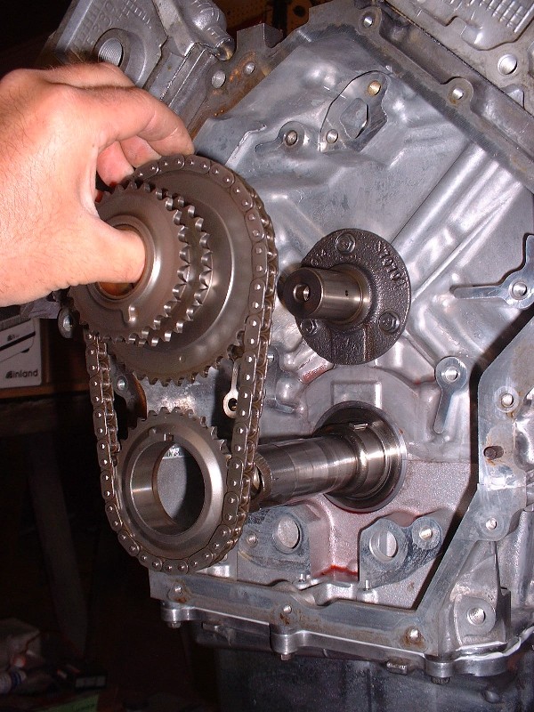
Next up is to install the crank sprocket, intermediate sprocket set and the chain all in one shot. Before you do that though, you have to align a pair of dots on the two sprocket sets so that the dot on the crank sprocket is pointing straight up and the dot on the intermediate sprockets is straight down. Again, it’s not rocket science or brain surgery. Both sprocket sets just slip right onto their respective shafts without any fuss. (The intermediate sprocket set is actually machined from a solid piece so you don't have to worry about aligning them to each other).
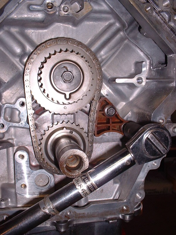
There’s a fair bit of slack in the chain at this point, so you want to make sure that the chain is tight on the side that gets the guide, and loose on the side that gets the tensioner. Here’s me installing the guide and torquing it to 18 lbft.
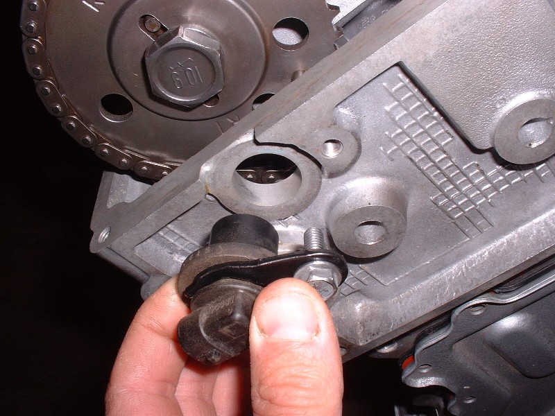
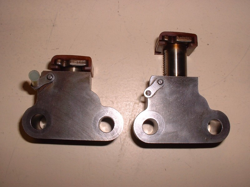
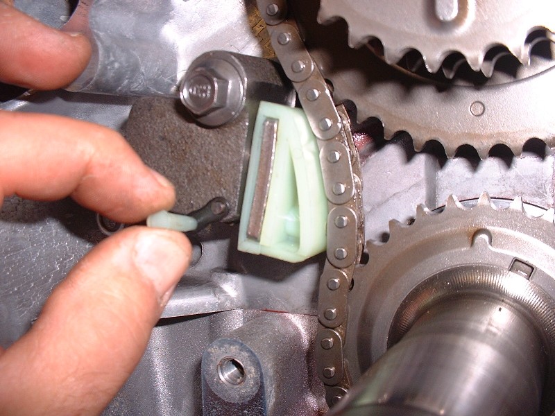
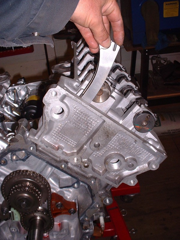
The last component to be installed is the tensioner. When you remove the tensioner on the teardown phase, it springs to its fully extended position. To reinstall it, you have to rotate a little spring loaded lever on the side of the tensioner, push the piston back into the block, and stick a peg in the hole in the little lever. The peg keeps the piston from shooting back out. Here’s a picture showing how much travel there is in these little suckers. (These are actually secondary timing chain tensioners, but the primary tensioner is similar, as you'll see in the next photos.)
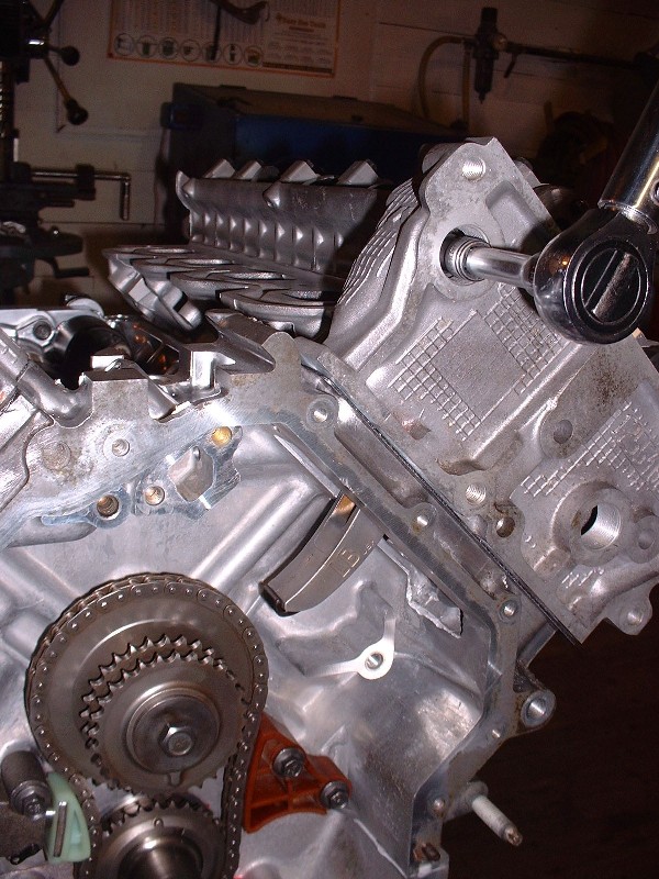
So here’s the brand new primary tensioner being installed. Again, just two bolts tightened to 18 lbft.
And finally, once you make certain that the little dots on the two sprockets are perfectly aligned, you pull the peg and let the tensioner take up the slack in the chain. Too easy. The cam chains on the other hand are a little more work. That's next.
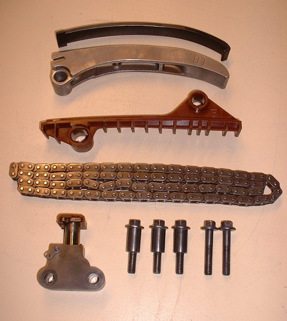
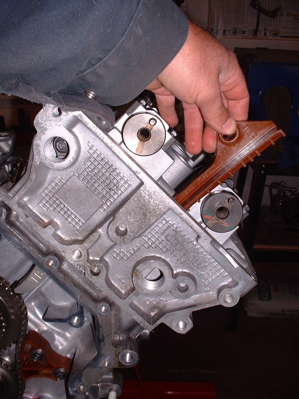
Here are the main components of the secondary timing chain system from top to bottom: replaceable upper chain guide shoe; upper chain guide; lower chain guide; chain; and tensioner.
The first step is to install the shoe on the metal upper chain guide and slip the guide through the top opening of the chain case (this is the guide that will have the tensioner pushing its backside).
On the front (or left, or even) cylinder bank, this guide is mounted above the chain and is secured in place with one pivot bolt that’s reachable through one of the holes that’s been bored and tapped in the front of the chain case like this:
The lower chain guide on this bank is made of plastic and it goes in through the top like the upper one, except it has two bolts that secure it in place.
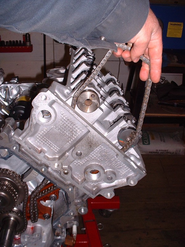
Once that’s done, you slip the chain through the top of the case as well, feeding between the two guides, and hang it over the ends of the cams like so:
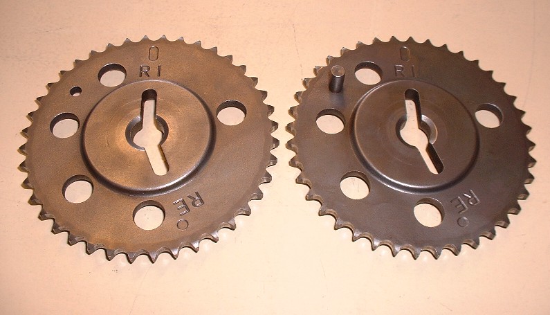
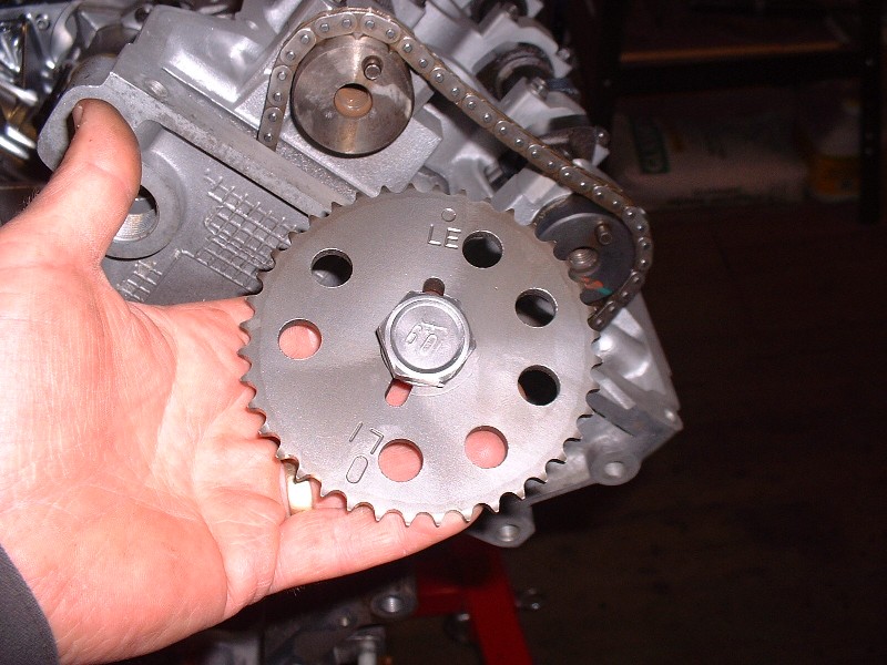
Even though the Northstar wasn’t used in any longitudinal applications at the time this ’97 was built, GM still called the different banks LEFT and RIGHT. So for the Fiero application, the left bank is the front bank, which are also the even numbered cylinders. You need to know this when you go to stick on the cam sprockets, which are next. The intake and exhaust sprockets on the left (front) bank are identical but they go on in different orientations. Here you can see that the locating pin on the camshaft slips into either of two slots depending on which cam it’s destined for (ie left intake cam (LI) or left exhaust cam (LE).
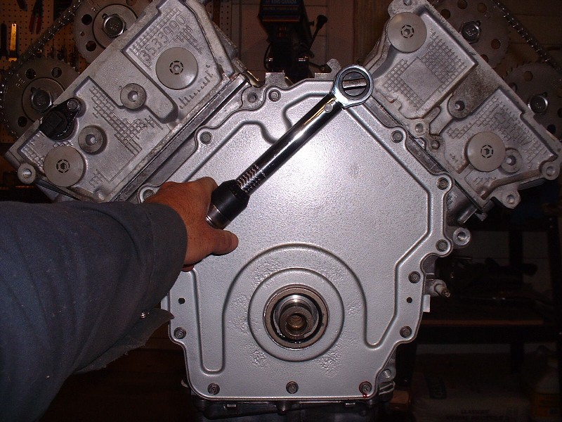
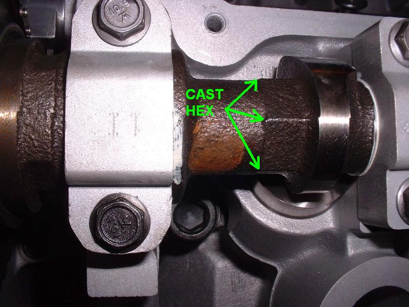
Before you can slip them on though, you’ve got to rotate the camshafts so the pin on the end of them is at 90* to the valve cover mounting surface. Because the cams are under a fair bit of tension from the valve springs, GM had the fore-thought to cast a hex onto the cams so you can turn them with a wrench… that was handy.
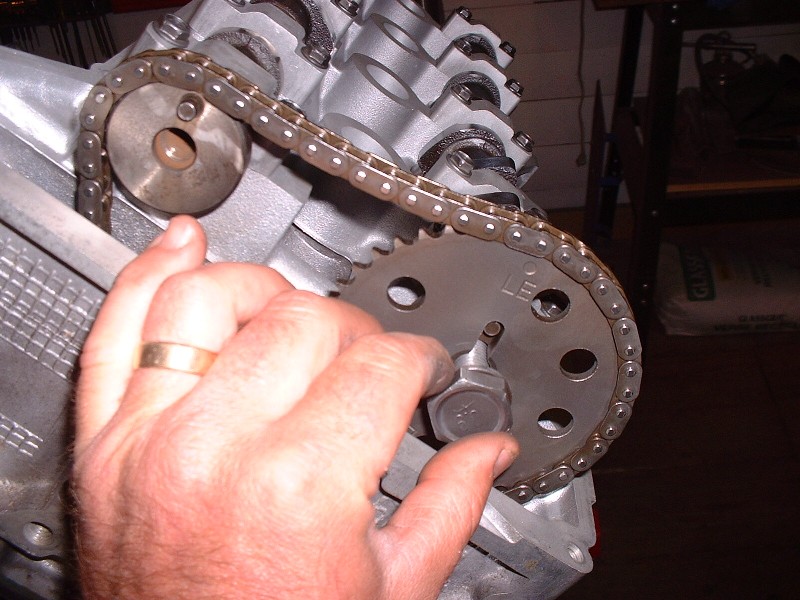
Next you slip the chain around the inner of the two primary sprockets down below, then slip the chain onto the exhaust cam sprocket in such a way that when the sprocket is installed on the exhaust cam, that there's no slack on the chain segment lying across the plastic lower guide. The chain should fit just right so if there’s any slack, double check that the dots on the primary sprocket set are perfectly aligned, and that the exhaust camshaft pin is at exactly 90* and turn either one as necessary.
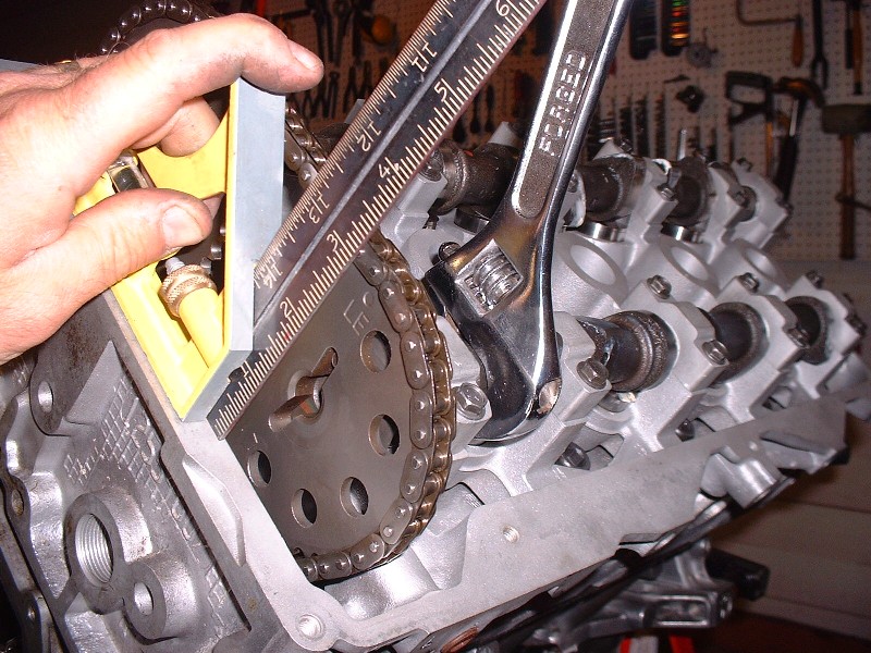
Once that’s done, then slip the intake cam sprocket onto the chain so that when it’s installed on the intake cam, that there’s no slack on the chain segment between the intake and exhaust sprockets. To do this, you may need to reposition one or both cams a little using the wrench because if either cam pin isn’t perfectly at 90* you’ll find it impossible to install the chain without it sagging between the sprockets.
At this point, all the slack in the chain should be on the chain segment between the intake sprocket and the primary sprocket down below. That’s because the chain tensioner is what will eventually tighten up that segment… but not yet.
The next step is to install the rear/right/odd bank chain set. It’s similar but not exactly the same as the front/left/even bank
[This message has been edited by Bloozberry (edited 07-13-2010).]
Mercy me... a Murci? Have you posted images of it here yet on PFF? What's it got for an engine? As for total engine costs I keep a detailed record of all my expenses to help the insurance appraiser come up with a replacement value for the car, should the need ever arise. The engine, engine parts, and machining to date (not including flywheel, and PCM tune) have cost me about $5150. Really not bad at all.
]
I have witnessed said Murci. I will let the owner explain her, but what a car! She definately has curb appeal. The lines are really proportionate, and not at all boxey or out of place. I have pics, but will post only if Dratts says it is cool. Oh, please let me post them?
And Dratts, I will be at FieroKing's tomorrow. Maybe it won't snow this time?
EDIT: As to not take up Blooze's space, I will post a thread in the General section. I have some very appealing pics of your car.
[This message has been edited by Tony Kania (edited 06-11-2010).]
Hey Tony, Sure, post away. It's got a 350 tbi vortec in it for now. It's at midtown motors ruight now getting a new interior. I'd post more but I don't want to distract from bloozes fantastic story. I'm learning more than I'll ever need to know about N*s but it's always nice to know what's under your hood.
Tony, thanks for posting those pics of Dratts car... that is one awesome looking ride. Dratts, that thing looks all Italian, but with that 350 TBI in it I'll bet it sounds all Detroit! Nothing one of your Northstar engines couldn't solve though. Charlie and I will walk you through it.
Anyways, I must admit when I went to install the rear bank timing chain parts, I started to doubt myself. In my head, I imagined the installation would be the mirror image of the front bank’s set-up, but came across my first hurdle when I went to install the upper guide. It wouldn’t fit no matter how I turned, squeezed, or willed it into place.
But then it struck me… if the chain guides were installed as the mirror image of the front bank (ie with both tensioned guides at the top) then the front bank would work properly but the rear would have the crank’s power being applied to the slackened segment of the chain. That wouldn't work well... remember the chain is only pulled, not pushed by the crank. So for the whole thing to work properly, the rear bank’s hardware would have to be installed as though it were removed from the front bank, lock, stock and barrel, and simply rotated around the crank's axis like the hands of a clock. (I have no idea whether that makes sense to anyone except me, but at least all the pieces fit!)
So once the upper and lower guides were in, the next step was installing the cam sprockets, as before. Except that one of the rear (right) bank sprockets has a pin on it that none of the others do. It pays to notice the little things because no mention of this is made in the Service Manual. The pin is part of the camshaft position sensor circuit. The sensor gets installed on the side of the head where the exhaust cam is (at least that's where the hole is!), so it became pretty obvious which sprocket had to go where.
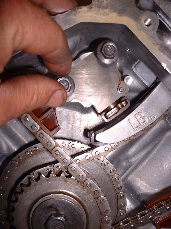
The rest of the installation is similar to the front bank. Once the chain is sorted out and the slack is on the proper side of each sprocket, the tensioners for both sides are installed and the little release pins are pulled. Notice the big “LB” for Left Bank (or lost bonehead).
To keep the road grime out, the access holes for the chain guide bolts are then plugged with threaded plastic bungs. They have an o-ring on the backside that seals up tight against the cylinder head.
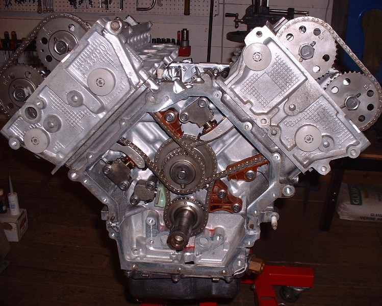
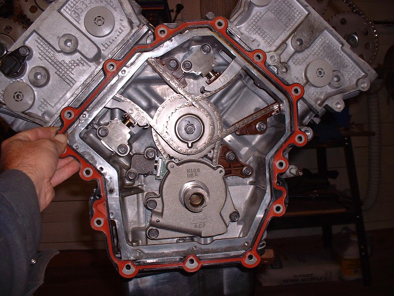
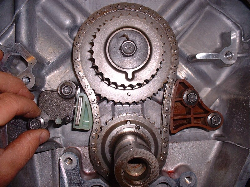
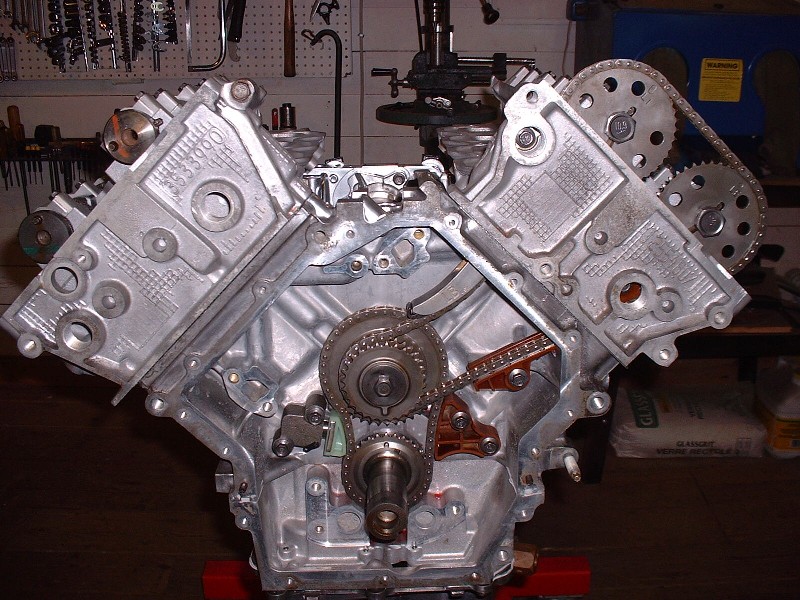
So when it’s all said and done, this is what it’s supposed to look like. Each chain has a stationary guide (on the powered leg of the chain) and a pivoting guide with a tensioner holding it tight against the return-leg of the chain. It looks busy, but it's really quite simple. Personally, I had expected it to be somewhat confusing to set up the timing chains after reading about the process and having seen other people’s threads, but it turned out to be straight-forward.
Looking good, nice to see some progress on the project. You have more guts (and money) than I do to rebuild a Northstar. Seeing how complex it is makes me wonder if I should have went with a 3800, I'll feel different when my swap is done. Did you consider a set of CHRFabs cams? I believe that they are only about $500 for a set. Beats $700 a piece and it's an upgrade, but I will be interested in how your refurbished cams hold up. Edit: Hooray! I own my first page ever!
agreed... its much cheaper to get a crate engine off ebay these days than rebuild an N*... i understand his angle though, as building it yourself is peace of mind, since you KNOW it will be done right, as long as one knows what one is doing
I’m back after a short break working on a ’67 GTO convertible… almost done. So after the chains were in place, I installed the camshaft position sensor in the hole next to the rear head exhaust cam sprocket. It senses the passing of the little metal pin on that sprocket for timing purposes. Like all of the the M6 bolts, the sensor hold down bolt goes on with 89 in-lb of torque. The difference with this little guy however is that it goes right through to the innards of the chain case so it needs a little dab of RTV on the threads to keep it from leaking.
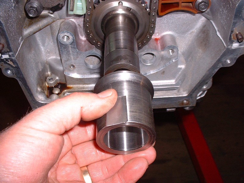
The last thing before the chain case can be buttoned up is the oil pump. I ordered a new one on spec as cheap insurance even though the old one looked OK. They're a pretty robust pump. I was surprised that the new pump came with a drive sleeve, because I can’t see why this part would need to be replaced. I used the new one anyways… it just slips onto the crankshaft.
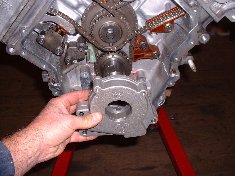
To get the new pump on, you simply line up the flats on the drive sleeve with the mating flats on the pump rotor. It too just slips on. Surprisingly, there are no O-rings or other seals between the inlet and outlet ports of the pump, and the mating surfaces of the block.
To hold the pump in place there are three screws that must be tightened in a particular sequence and then turned an extra 35*, and you’re done.
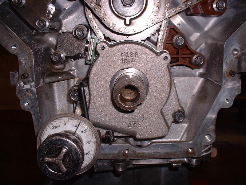
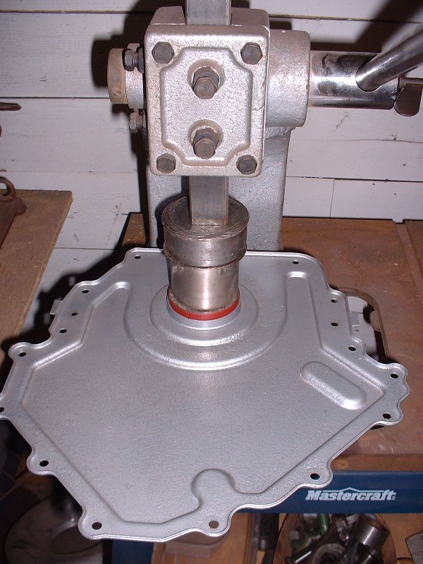
Before the chain case cover can go on, there’s a couple things you have to do. The first is to replace the front crank seal in the cover. Getting the old one out was a cinch… I just used my arbor press and pressed it from the front side, out through the back side. If you haven’t got a press, then a few carefully placed hammer blows with a punch would do the trick.
Getting the new one in wasn’t as easy. No matter what I did, the seal always seemed to get started cockeyed. I worked at it for fifteen minutes trying to get it to start all the way around to no avail. It’s as if the seal was a smidgen too large for the hole. So I decided to use my Dremel with a small sanding drum and chamfered the edges of the hole in the cover. Once that was done, the seal pressed straight in.
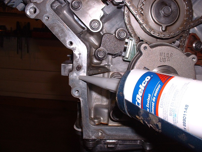
The second thing to do before the cover goes on is to use a straight razor and slice off any engine sealant that oozed out or is protruding from the case-half split line at the front of the engine. Then you’ve got to place another dab of fresh sealant in the same two spots.
The third thing is to put a new cover gasket in place. It’s got two holes that line up with corresponding alignment pins so there’s no need to try to hold everything in place. The new seal came with the master engine rebuild kit. It’s made of a hard composite material that’s got an orange neoprene-like seal impregnated in it on both sides.
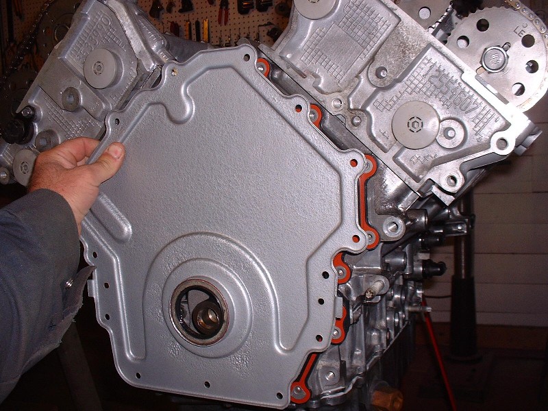
Finally the cover gets put in place… forever sealing up the beautiful mechanical artwork underneath. My cover was a little pitted so rather than filling the pits with body filler, I sandblasted it, primed it, and sprayed it with a Tremclad silver paint that gives a “hammered” look to it once dry. I didn’t want to waste too much time on a part that will not be seen.
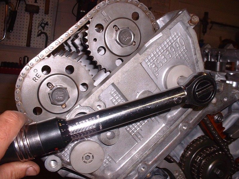
The cover gets torqued on (you guessed it) to 89 in-lbs starting at the bolt I’m torquing in this picture, and going around successively to the next bolt in a clockwise direction until you’ve done all fifteen. Then, if you’re smart, you go over them one more time. The service manual states that a thread locking compound must be used on these so I used the high temp red Locktite left over from my head bolt inserts.
Originally posted by Bloozberry: I didn’t want to waste too much time on a part that will not be seen.
Given the amount of time you put into that starter, that's kind of funny that you'd say this about the timing cover. Maybe the starter taught you a lesson?
Thanks for the documentation, I enjoy reading/seeing it!
Hey! You're not supposed to notice little deviations like that... just read the story and go with the flow. (Actually, I rebuilt the starter for peace of mind... I didn't fill the scratches on it with body filler either!)
The Northstar looks familiar to the engine I tore down and put back together in school. Mine was a V6 with the one piece main caps and had dual overhead cams. But I think it was a Ford. I don't know about the N*, but the V6 had it where only one of the intake valves per cylinder where getting air for the lower RPMS. It had a set of butterflies in the lower intake manifold that would open to let air get to the second set of intake valves, which I think was controlled by the computer with an electronic solenoid.
I finally moved that '67 GTO I've been working on out of the shop and will get back to the 'Blooze-Zone' after the long weekend. More to come soon. Thanks for the interest!
Litebulb... you were probably working on a Taurus SHO engine... made by Yamaha. That was a nice powerplant while it lasted.
So much for intermission… it’s back to work! I’ve been toiling over what to do with my valve covers. On the one hand I’d like to shave off all the little bosses on the “ugly” cover, pretty it up with some stick-on grooved caps (like some I’ve seen here on PFF but forget whodunit), and paint them lipstick red, or fly-yellow since the car will eventually be yellow. Orrrrrrrr… spring for a pair of those obscenely expensive cast, ball milled and polished CHRFab beauties. Maybe some of you could give me ideas on what you’ve done?
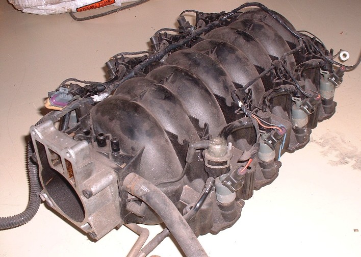
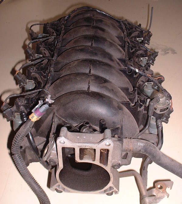
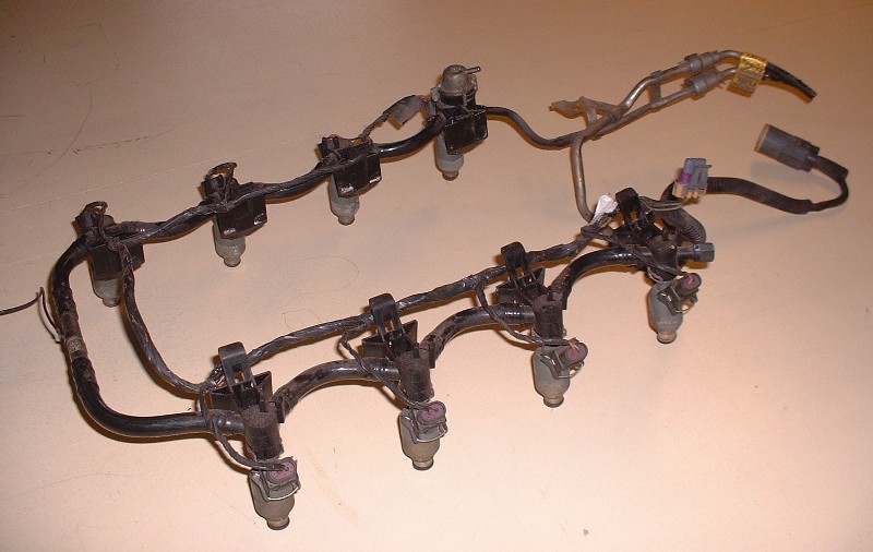
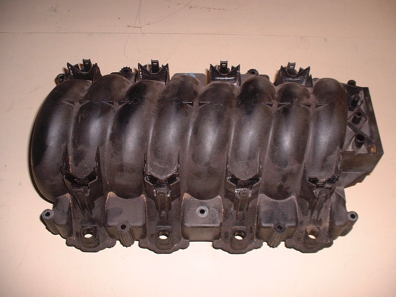
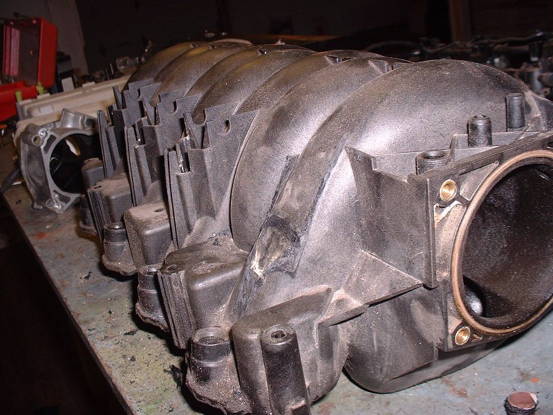
While I sit on the fence with regards to the valve covers, I’ve pretty much made up my mind that I’m not going to use the Caddy beauty cover. I may design something later to cover up the intake plenum, but for now I’ve decided to make the plenum as appealing as possible. To that end, I made a few inquiries last week here on PFF about replacing the really busy looking plastic fuel rail with the very sano-looking stainless rail. The stainless rails were installed as a result of a recall in the USA for ’95 to ’97 cars but not in Canada… so it looks like I’ll have to buy one. Here’s the stock plenum in all its complexity.
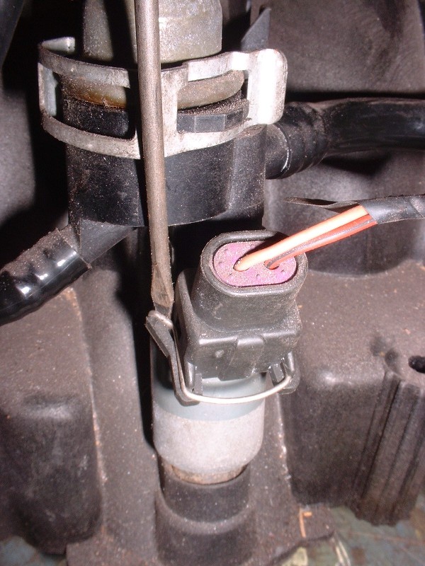
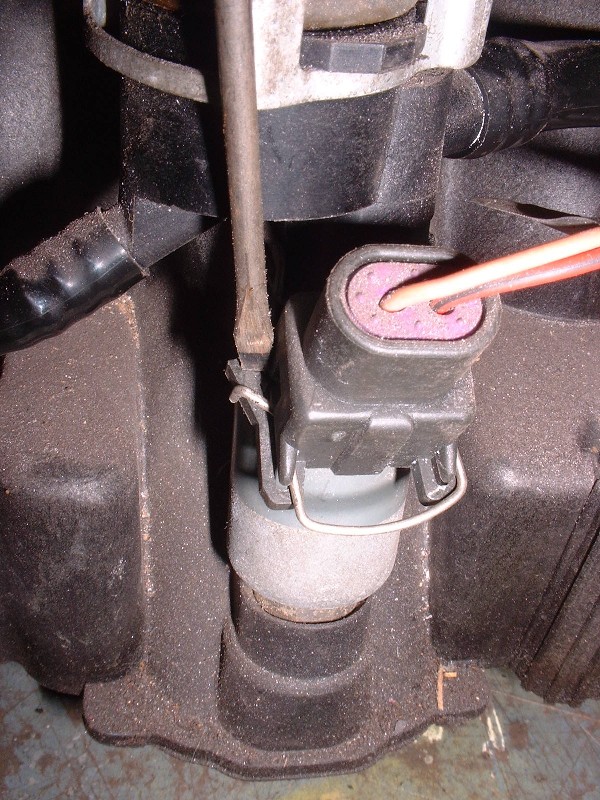
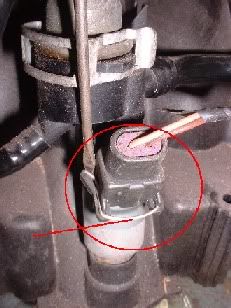
I started the dismantling process by removing the connectors on the injectors. If you’ve never done it before, they’re the same as on the Fiero V6’s… you need to take a small screwdriver to a little spring clip that wraps halfway around injector.
Then with a little twist, stretch the end of the clip off the plastic tooth that captures it like this.
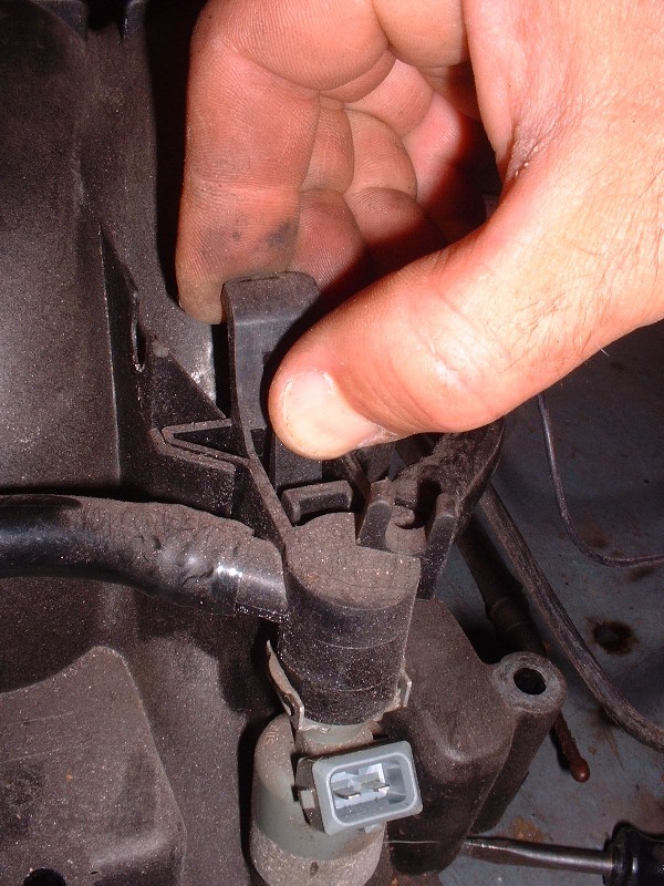
Its easier to remove the fuel rail itself once you’ve removed the electrical connectors since the wires are partly in the way. Here I’m pressing the plastic release lever on the fuel injector rail to be able to remove it from the plenum.
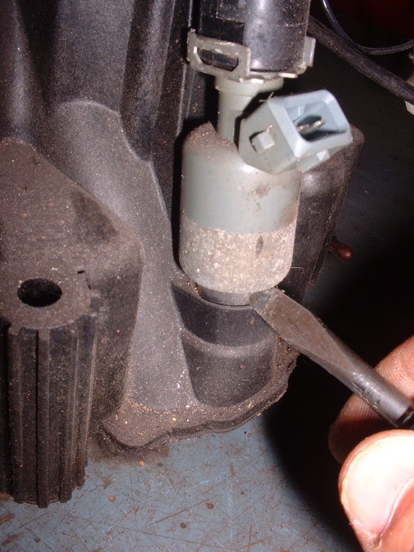
I found that the injector o-rings were stuck in the plenum so a gentle pry with a screwdriver broke the tight seal and got things moving.
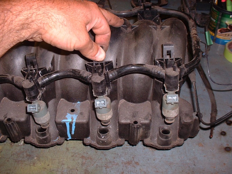
Because the plastic fuel rail is quite rigid, I had to release all four injectors on each side, working them up a little at a time before being able to lift the whole rail up and off the plenum.
So here’s the old rail. I’ll need to remove and have the injectors cleaned to get them ready for the stainless rail. To further clean up the top of the engine, I’m working out an idea to hide the injector harness under the plenum and have the connectors come up through an access hole I’ll drill for each pair through the plenum mounting area.
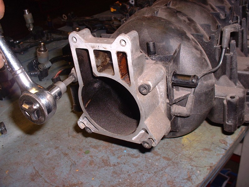
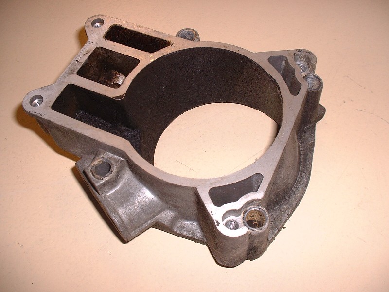
To finish stripping the plenum of hardware so I could clean it properly and assess just how many brackets and bosses I could shave off, I removed the throttle body adapter:
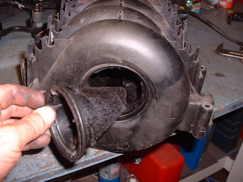
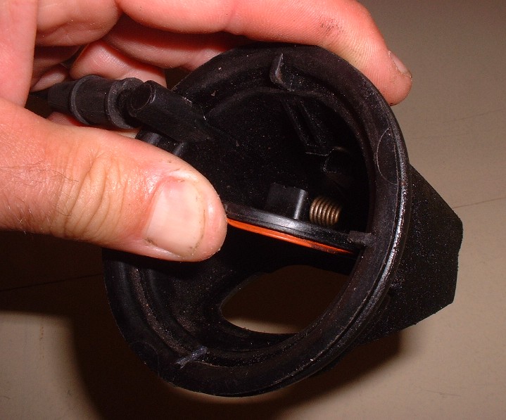
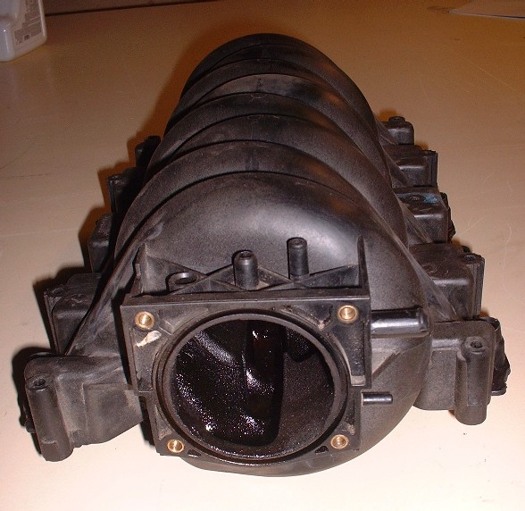
…and this spring-loaded trap door at the rear of the plenum. I would imagine this is a pressure valve in the event of a backfire. I could be wrong. It’s easily removed with a simple twist and a pull.
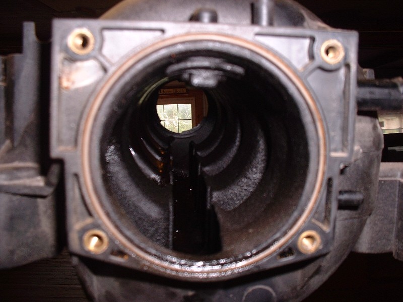
Here’s what the inside of the plenum looks like. All the runners open into the common central part of the plenum at the bottom. They curl around a total of about 270* of which the first 180* are circular, and the last 90* gradually straighten out into a flat run into the intake port. You can see from mine that there’s a fair bit of oil and carbon deposits in there. I’ll explore different ways to clean out the runners without trying to melt the PVC plastic that they’re made of! Hot soapy water in the pressure washer comes instantly to mind, but I’m open to suggestions.
Just a tip for you. If you push on the center of the "clip" - push it toward the injector, you can pull the injector plug off - no need to pop one end of the clip out of the connector.
I took my plastic intake plenum to an engine rebuilder for cleaning and they couldn't clean the carbon out. They tried the hot tank, everything. The shine came off but not the carbon particles. I've also read that they are supposed to be replaced instead of cleaned because of the inaccessible areas that can't be cleaned that hold carbon deposits.
Katatak: "Whale oil beef hooked!" (say it with a Newfoundland accent... "Well I'll be f___"). All these years I've been painstakingly unclipping those rotten injectors with a screwdriver. Thanks for the tip!
Will: Really? The pictures of the stainless fuel rails I've seen all seemed to have the FPR installed on them. Here's one for an Aurora on ebay that's supposedly new. Is that just the mounting boss on the rail and not the FPR itself?
IXSLR8: I had read that the plenum's were to be replaced rather than cleaned in the service manual too. But I have a hard time believing anyone would do that. I haven't priced them out but I don't imagine they're cheap! Other than to make profit, for the life of me I can't understand GM philosophy (scratches head). If even the hot tank can't remove the carbon deposits, then I don't think we have to worry about them accidentally falling off into the engine, and I can't imagine there ever being enough deposits to choke off a runner. All I want to do is to get rid of the excess oil just pooled there in the bottom.
Can't you just pinch the wire retainer in with your thumb? On all of mine, I just push in on the wire retainer, and it spreads out at the back, allowing you to just pinch & pull, and the connector slides right off.. Or maybe these are different than the 3800's... Sure look the same though.
Edit: Looks like somebody beat me to it.. oh well.
------------------ ---------------------------------------------------- Currently in the middle of my 88 + 3800NA swap
[This message has been edited by aaronkoch (edited 07-13-2010).]
This thread is due for the Construction Zone! I know you don't like the stock beauty cover, but I believe that the 93-94 engines came with a magnesium one that can be polished. There was a member on here who had one, looked realy good. I have yet to find one though.
LOL! Yes. I didn't replace my intake either. Just used it after I couldn't get it all cleaned up as stated. The pools of oil is a natural N* attribute. I've had it off after it was cleaned and spotted the oil in there again...even with the heads all redone. If you delete your EGR system, its not supposed to carbon up any further. I deleted mine.
The fuel pressure regulator is a plug and play type set-up. You just take the clip out of the rail housing and pull the regulator. you can clean it up carefully as Will mentioned. Look for "O" rings and small fuel screen. The nice thing about the regulator is that its adjustable. You can counterclockwise and clockwise the screw and get more fuel pressure. Sort of an alternative for larger injectors for the mild cams. I'm getting ready to set mine at 65lbs.
Originally posted by Bloozberry: Will: Really? The pictures of the stainless fuel rails I've seen all seemed to have the FPR installed on them. Here's one for an Aurora on ebay that's supposedly new. Is that just the mounting boss on the rail and not the FPR itself?
Maybe it's different by application, but I ordered the part number for the correct connection locations (via Russ' thread on the matter) and the FPR pot was empty. Moving it over wasn't hard, but as I said there are small parts.
When I got my stainless fuel rail from the local GM dealership it was without the FPR. The good news (for me anyways) is that the new FPR was inexpensive. I think it was around $20. I could have used an older one but I found some info around that suggests that these FPR's have a tendency to fail and let fuel into the vacuum line. I don't know what a new one will cost where you are so cost may be a factor.
Hey! A new home in the Construction Zone! I like the company in here!
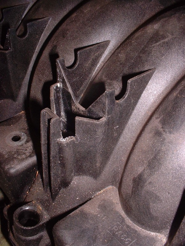
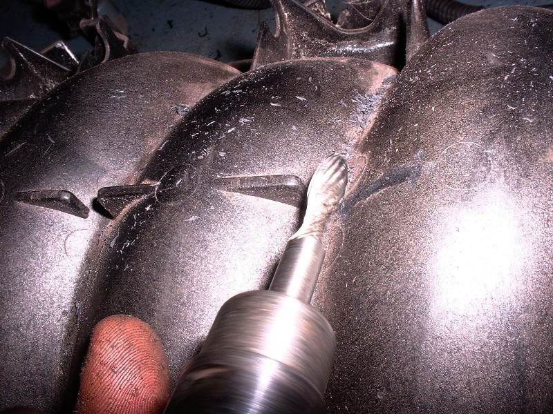
Anyways, before giving the plenum a bath, I figured I’d get some of the messy work done and over with, so I decided to give this porcupine a shave & haircut. Here’s what I’m talking about:
Notice all the fuel rail mounting brackets molded into the sides of the plenum? Here’s what they look like close up. They’re no longer needed when the stainless rail gets installed.
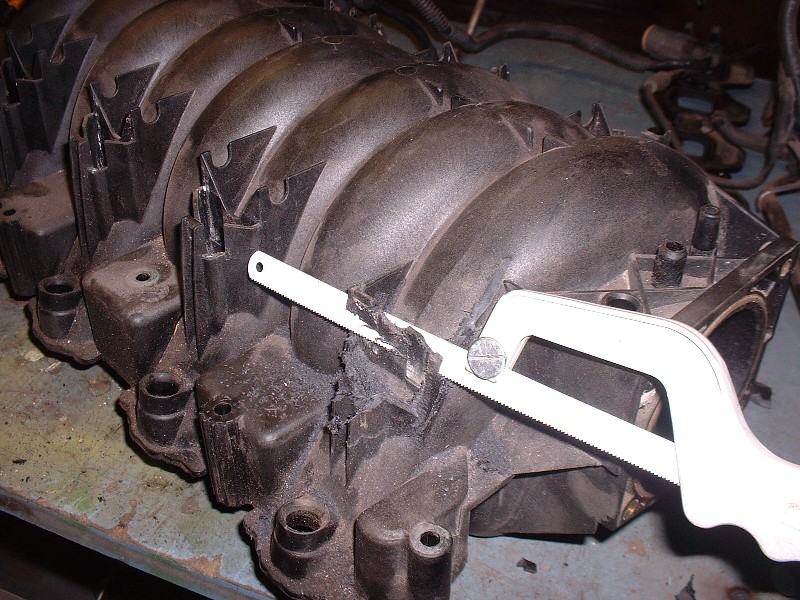
At first it seemed like it would be an easy, quick and dirty task. I started out using a hand hacksaw to be able to control the cutting more easily, but found that the blade wandered a lot. The plenum runners weave in and out a bit too so you can't get a straight line of sight with the saw. I had to cut with the blade bent in a U shape which makes controlling it much more difficult.
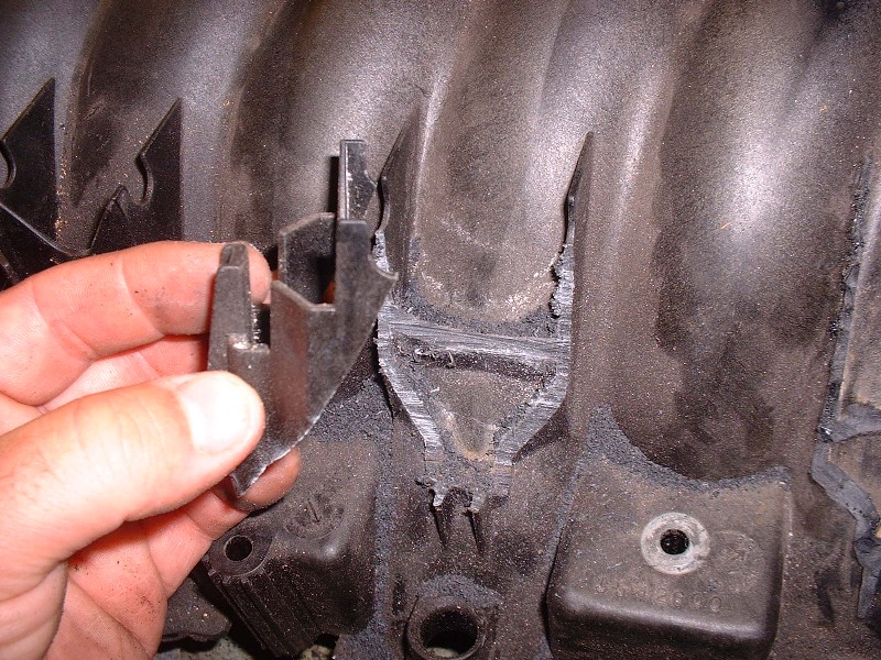
Here’s the first “ear” lopped off. Notice how the plastic rail mount gets thicker towards the bottom of the runner as the angle between the runner and the mounting boss gets shallower. This is where the greatest work ended up taking place.
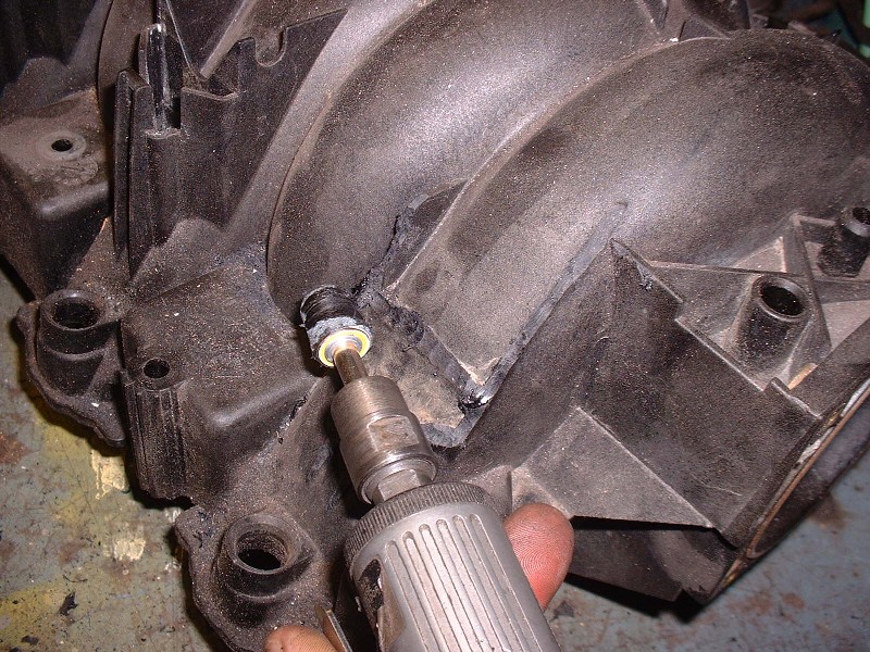
At first I thought I’d be able to use a grinding stone on my die grinder to make quick work out of smoothing off the left-over plastic, but from this photo you can see what happened within the first couple seconds of trying that idea. The stone just heated up the plastic and made it stick to the stone like Bubblicious on a summer sidewalk.
Next I tried a hand file but found that to be waaaaayyyy tooooo sloooow. And you can forget about sandpaper too… the PVC plastic just gums it up after a dozen or so passes. My breakthrough came when I tried a set of high speed multi-fluted dies. I tried one out on the spark plug wire clips molded into the top of the plenum and it worked like a charm. It chops instead of grinds so it doesn’t heat up the plastic and it was very easily controlled at high speed.
Here’s what the first boss looked like once it was lopped off and roughly smoothed. One of the things I found as I was shaping the lowest part of each fuel rail boss is that the mold line for the plenum must run under the bosses. If you look carefully, you’ll notice that the runner carries on in a nice smooth line under the first web (from top) that crosses the runner. But as it gets to the solid bottom part of the boss, the outside runner wall takes a bit of a step. GM obviously wasn’t expecting anyone to shave the bosses off so whether the mold halves lined up perfectly under them or not probably wasn’t a big concern. Oh well… nothing a little body filler can’t cure.
The other tough part was shaving one of the two vertical webs of each boss because it starts on the base of one runner, crosses over the valley between the adjacent runner and carries on part-way up that adjacent runner at a very shallow angle. If you look at the forth image in this post you’ll see what I mean. It’s the vertical web on the left side of the boss pictured that's a headache. Anyways, getting the tool to follow that eccentric path without slipping and nicking either runner is pretty difficult. More Bondo!
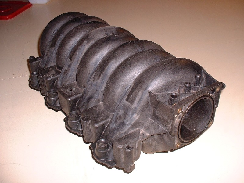
Here’s a couple shots of the intake plenum with all the unnecessary brackets shaved off, and with only two or three little nicks. Bring on the aftershave and the Kleenex bits! Next stop… the hot tub.
Katatak: "Whale oil beef hooked!" (say it with a Newfoundland accent... "Well I'll be f___"). All these years I've been painstakingly unclipping those rotten injectors with a screwdriver. Thanks for the tip!
Will: Really? The pictures of the stainless fuel rails I've seen all seemed to have the FPR installed on them. Here's one for an Aurora on ebay that's supposedly new. Is that just the mounting boss on the rail and not the FPR itself?
IXSLR8: I had read that the plenum's were to be replaced rather than cleaned in the service manual too. But I have a hard time believing anyone would do that. I haven't priced them out but I don't imagine they're cheap! Other than to make profit, for the life of me I can't understand GM philosophy (scratches head). If even the hot tank can't remove the carbon deposits, then I don't think we have to worry about them accidentally falling off into the engine, and I can't imagine there ever being enough deposits to choke off a runner. All I want to do is to get rid of the excess oil just pooled there in the bottom.
I feel your pain - took me 4 years to learn that - by mistake I might add.
Looking great Blooz - Welcome to the construction zone!
Pat
[This message has been edited by katatak (edited 07-17-2010).]
Thanks for all the up-dates. I can't see my self changing the 4.9, unless I win the lotto. But I think it is great that you are sharing for all those that will go the Northstar route.


 I will let the owner explain her, but what a car! She definately has curb appeal. The lines are really proportionate, and not at all boxey or out of place. I have pics, but will post only if Dratts says it is cool.