Ahhhh yes... the Honey-Do List... every married guy has one longer than his arm.
Speaking of lists, I have a little more progress to report on Blooze-Do List: I finally managed to complete the three-view of the front lower control arm drawing. What a bear this thing is. It has such a convoluted shape on the underside that around Hour 15 of trying to draw it, I realized that for my simple static analysis, I only really need to have a stick drawing with the essential dimensions on it. But then, how interesting would that be? So 20 hours of drafting later, here's the latest in the series of suspension drawings (I wouldn't try to make a set from scratch using my drawings ). The knuckle is next.
Three-view:
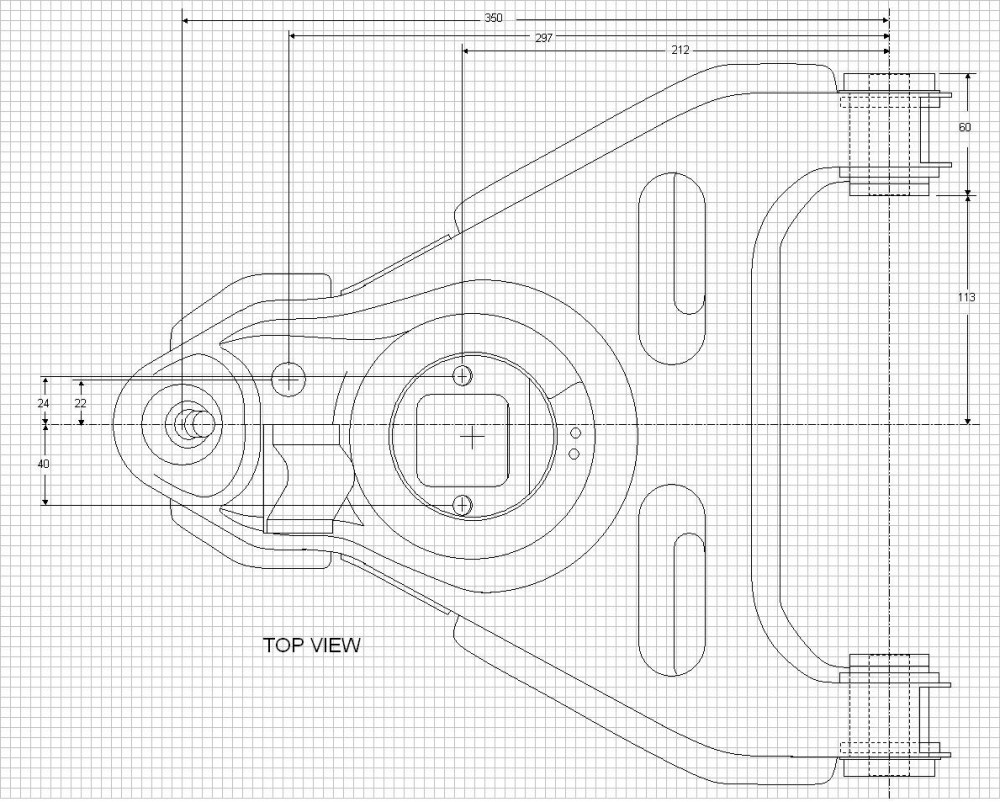
Top View zoomed in:
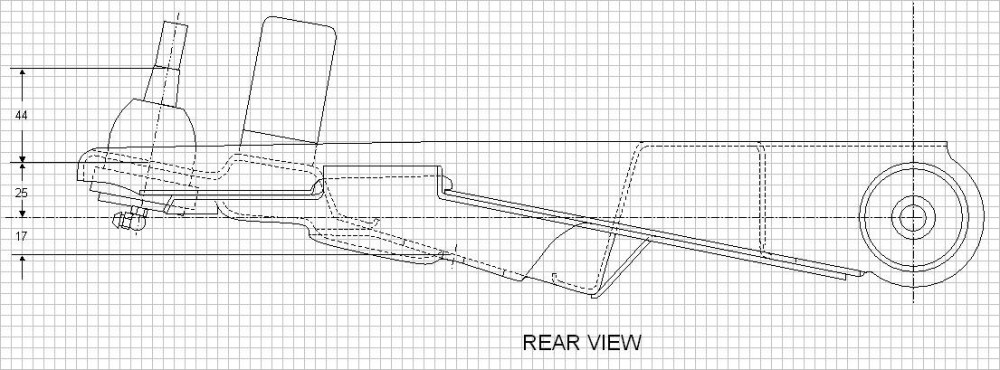
Rear View zoomed in:
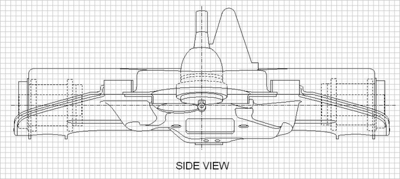
Side View zoomed in:
[This message has been edited by Bloozberry (edited 09-29-2011).]
Only a few more pieces to go and this stock suspension stuff should be over and done with. That will allow me to get on with designing the new rear cradle and hopefully prove the changes will result in improved geometry... at least on paper. But then that's all I'll need to do to satisfy the looming legislation here in Canada which would place strict certification processes on modified suspensions.
Enough of that. I've been slaving away in my spare time getting the front knuckle drawn up. It was a little challenging since there are some interesting angles which complicate getting accurate measurements, but after double and triple checking things using alternate measuring techniques, I'm confident it's very very close. What made matters worse is that I wasn't able to separate the bearing assembly from the knuckle as I did for the rears. I would have had to take the assembly to a shop with a hydraulic press to get them apart. If I had planned to actually use these knuckles and bearings, I would have done that, but since they're only being used for camparison's sake I drew the parts stuck together, like they are. Here's the three-view:
One interesting issue I found is that the P22 parts book lists the RH and LH knuckle part numbers as 10046484 and 10046483 respectively. However cast right into the RH knuckle I used is part number 10048486 with additional castings GM and 84. Are there earlier and later versions of the 88 knuckles?
The next hurdle will be to try to accurately measure the dimensions of the upper and lower ball joints. The center of the pivot point won't be easy to determine with any great accuracy. I tried Googling ball joint dimensions, and schematics, and specifications, and drawings... nothing came up. I did find an obscure thread somewhere where a guy was trying to do the same thing as me for his Honda. He was told by Moog and several other manufacturers that they didn't release that information since it was proprietary. As if we're all going to start making our own backyard ball joints! Hopefully I'll be able to figure out a way without resorting to cutting one of each up. Anyone have any leads for the data or ideas on how to measure it?
(Edited to update drawing)
[This message has been edited by Bloozberry (edited 11-16-2011).]
When I modeled the miata ball joints I'm using for my locost i moved the joint all the way to one side and drew a line down the center of the joint, then moved it to the other side and did the same. I then used the intersection point as the center of rotation. I feel it worked reasonably well but without cutting it apart there's not much else you can do.
[This message has been edited by Zac88GT (edited 10-09-2011).]
Thanks Zac and Gokart. For Zac, I used your suggestion and it seemed to have worked relatively well. The upper is now done, I just have to work on the lower one now.
For Gokart Mozart: I looked at the four links you provided but only found the third link helpful. On page 18 there was a cross section schematic of an upper and lower ball joint which helped me to visualize the guts a bit better. Not exactly sure why you posted the other links though.
Hey Booz. I dont know if you would be interested or even if you are allready fallowing the build. But under the General Fiero Chat, there is the topic of "My Mera Style 308 Project". The only reason I bring it up is he makes some pretty nice 355 taillights. I've noticed you have the same crappy outer lenses I have and just thought you might be interested. Currently he has posted pictures of the f355 taillights but hasnt put a price on them but Im sure I will be a customer.
Thanks for the tip 5150fauxarri. But I'm one step ahead of you! A couple months ago I bought a set of new OEM tail lights from Don Ostergard here on PFF who was getting out of an F355 project car.
This week I worked on the ball joints and the front upper control arm mount. Trying to determine the exact center of the ball joint pivot points was a little daunting at first, but I came up with a measurement method that estimated the location within the precision needed for this analysis. I removed the boots and cleaned the grease from the exposed part of the ball, then swung the stud all the way to one extreme of the permissible movement and measured the lateral and vertical displacement of two fixed points along the centerline of the stud. Then I swung the stud to the other extreme and did the same. These four points described two converging lines that intersected at a point where the pivot center should be. I repeated the measurements several times for each ball joint and then used a bubble level protractor as a back up method, and not surprisingly came up with a very round measurement for both ball joints; 25 mm (or 1 inch) below the lower edge of the where the taper stops on the studs. It makes sense too that a ball joint manufacturer would use common dimensions for these sorts of things rather than some odd number... at least that's what I tell myself trying to rationalize my results!
Here's the upper ball joint. One interesting note is that both ball joints insert into their respective tapered holes in the knuckle right up to the depth where the taper on the stud ends:
And here's the lower ball joint. You'll notice that I didn't include as many measurements simply because not all of them are important, and outside dimensions may differ between manufacturers:
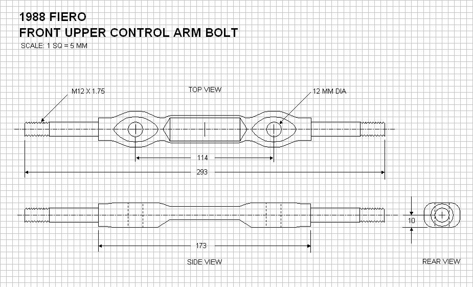
Finally, a simple little drawing of the upper control arm mount.
One last drawing to do before I can start sticking all these pieces together: the steering tie rod.
(Edited to update both ball joint drawings)
[This message has been edited by Bloozberry (edited 11-16-2011).]
Thanks 5150fauxarri... but I'm a bit of a pack rat when it comes to spare parts. Once this project is done, I'll have 3 roadworthy Fieros to try to maintain!
Well, it's been a while since I posted an update here, but not because I haven't been working my buns off. For starters, as I began piecing the various front suspension component drawings together to create the complete front suspension illustrations, I realized that some pieces weren't fitting exactly right. But I rather expected this since there are so many hundreds of measurements that I was bound to make a mistake or two. Piecing the parts together is sort of like a sanity check... if things don't fit, then there's obviously an error.
For those of you who may be copying some of my drawings to your own computers, you'll want to revisit the four drawings of the front cross member on page 11. I updated the spacing between the lower control arm mounts and tweaked a few other related measurements. Also, I've replaced both ball joint drawings on this page as well since I had forgotten to include the range of movement in the side views.
As for new work, I've drawn up the tie rod recently. There was nothing noteworthy about this drawing (Edit: updated drawing to Version 2):
Now for the part that's taken me eons to get right... the full front suspension illustrations. Just for curiosity's sake, I've been tracking my hours on this build in an Excel spreadsheet since the beginning. (It'll make for some interesting conversation later once it's done, and possibly even help the appraiser determine some value for the time put in it). This next set of drawings has cost me 30 hours to date, and I'm still not finished. I'm posting the side view first as I continue to work on the other two views.
The difficulty so far has been trying to determine the correct angles of the control arms at ride height, and then drawing them at these angles. The earlier 3-view drawings I made of the arms were created at angles that suited the ease of drawing them, not as it turns out, at the actual angles they sit at when the car is at ride height. Here is where having done these in a CAD program would've made things exponentially easier. I can tell you right now that the jounce and rebound drawings later on are going to be stick figures, not illustrations like I did for the rear suspension! (Edit: updated drawing to Version 2)
Anyways, the noteworthy aspects of this side view drawing are that:
1. the tire dimensions were taken from the average between four actual stock-sized, new front tires (P205/60/15) at 32 psi installed on two different '88 GT's, so that's how the rolling circumference was determined;
2. the lower control arm angle was determined by a measurement specified in the '88 service manual on page 3-16. It states that the difference in height between the lower corner of the lower ball joint and the frame rail directly inboard of the joint should be 6.9 mm. Having done this, the upper flat surface of the lower control arm sat at an angle of 7.5 degrees pitched downward towards ball joint end;
3. once the lower control arm was drawn correctly, the knuckle was added after being tilted for 5 degrees of caster; and
4. finally the upper control arm angles could be determined, and the upper arm drawn accordingly.
This side view will be used later on to determine what percentage of anti-dive is built in to the stock '88 suspension. Those of you who are more wiley and ambitious can already figure out this value from the info I've posted here and earlier.
[This message has been edited by Bloozberry (edited 11-19-2011).]
Thanks 17Car for the comments. I wanted the source drawings to be accessible and modifiable by as many people as possible, even those without CAD software, so I chose the very common drawing software tool that comes with the basic the Microsoft Office Suite. I use Microsoft Excel as the backdrop for the images after having forced the gridlines to squares. The resulting image is a vector drawing (scalable), but is essentially a line drawing that isn't renderable into 3D. That's the drawback to making it available to everyone. I haven't yet posted the source files since I continue to find small errors as I piece the components together. Once I feel they're at a stage where they are as good as I am am prepared to draw them, I will look for a site to host the files for anyone to download.
Now on to a few corrections to earlier drawings For those of you following this thread and downloading the drawings, you'll want to update your files with new pictures of the tie rod above, to which I've added the degrees of motion to the side view (you'll note that it's annotated Version 2). Also, I noticed several errors in the original drawing above titled 1988 Fiero Front Suspension LH Side View so I corrected them and annotated it Version 2 as well. The errors consisted of miscalculated front cradle mounting height and the ground clearance to the bottom of the cradle. As well, I noticed that I hadn't completely drawn the lower profile of the lower control arm which further reduces the overall ground clearance. If I discover any other errors I'll just keep changing the Version number and call attention to the changes in future posts. Likewise, if anyone sees any errors, please do not hesistate to let me know so I can correct them.
Finally a new drawing to add to the collection: the rear view of the front suspension (Edit: updated to version 2 - corrected location of outer tie rod end):
There are a few noteworthy details in this drawing:
1. The '88 front track width (59.7" or 1516.5 mm) was taken from an article in Road & Track (Oct '87). I've found the track width reported in several magazines and books to be erroneously listed as 57.8" including Gary Witzenburg's Fiero, Pontiac's Potent Mid-Engine Sports Car;
2. The camber is set to zero degrees in accordance with the alignment specs.
3. The kingpin angle is 6.0 degrees according to Gary Witzenburg's Fiero, Pontiac's Potent Mid-Engine Sports Car;
4. Neither the upper nor lower A arms are horizontal as viewed from the rear (or front) at ride height. The upper A arm is angled at 6.2 degrees upwards, and the lower A arm is angled at 7.5 degrees downward as measured from the top surface;
5. The scrub radius is an unverified 40 mm as I was unable to find any referenced documentation identifying the actual measurement. It's interesting that it's as large as it is despite the front wheels on the '88 being only 6" wide and having a relatively large 37mm offset;
6. As reported earlier, the center of gravity sits at 19.5" above the ground according to Road & Track (Sept 1983). Admittedly this is for the four cylinder cars, but I am assuming the CofG height most likely did not change significantly with the V6. It's longitudinal location did though;
7. The outer tie rod end is situated about 15mm outboard of the plane defined by the upper and lower ball joints. This results in built-in understeer as the roll angle increases. For there to be no effect, all three would have to align in the same plane; and
8. The shock absorber and the sway bar were left out to simplify the drawing
I think that's all that's pertinent about this drawing for now. Next up is the top view, and then on to some basic geometry analysis.
[This message has been edited by Bloozberry (edited 11-19-2011).]
Just got done reading through your entire build, very impressive! It's seeing builds like these and the attention to detail that got me excited about Fiero's in the first place, and keeps me motivated to work on my car. Keep up the amazing work!
For Yellow87FieroGT: Yes... the front track on the '84-'87's is 57.8 and the rear track is a bit wider at 58.7 according to many different magazine sources.
Edit for speeling
[This message has been edited by Bloozberry (edited 11-18-2011).]
A quick note for those of you saving copies of my drawings: I made an amendment to the drawing above entitled 1988 Fiero Front Suspension Rear View. The latest version (V2) above has the outer tie rod end raised about 5mm higher than Version 1. The reason is because I realized I had not rotated the knuckle to match the built in castor in this view which placed the steering arm on the knuckle lower than it should have been.
Now for the last of the layout drawings, here is the '88 front suspension assembly as viewed from the top:
There aren't many noteworthy aspects to this view except:
1. the difference in control arm lengths is quite apparent;
2. other than a symbolic rack, I didn't include the steering rack and pinion assembly... just too much work for no added value;
3. in the notes, I forgot to mention I left out the sway bar. I'll correct that only if other changes become necessary.
Everything in these three last drawings can pretty much be summed up with the values I've tabulated in the chart below under the heading "Coordinates". The "Static Data" portion of the table contains some measured and some calculated data. All the static data points are directly measured except for the roll center, swing arm length, and anti-dive, which are calculated. I go into how these are calculated in a later post. (Edit: updated chart added).
With the right formulas, this data is all that's needed to calculate the change in caster, camber, tire scrub, toe, front swing arm and side swing arms for any given amount of jounce, rebound, or roll. I know all of this because Herb Adams book tells me so. Too bad Herb doesn't get into the detailed formulas, referring instead to a computer program he uses... great help
[This message has been edited by Bloozberry (edited 12-08-2011).]
As with the front suspension coordinates, I've tabulated the rear suspension coordinates in the same format for anyone to use.
Once again, given the coodinates in the first part of the table, the swing arm, rear roll center height, and anti-squat can be calculated as I've shown on page 9 of this thread for the rear end.
(edited to add updated table)
[This message has been edited by Bloozberry (edited 12-08-2011).]
I used Lotus Suspension Analyzer. I can export a report to Excel with all the data so PM me you're email and I'll send it to you. I'll get to work on the rear suspension, probably won't take very long.
There are a couple things to notice right away from these graphs. Under bump the rear toe barely changes but it does toe in slightly, which is good. The front toes in on bump which is undesirable because it accentuates the steering input as the car rolls. Rear camber gain sucks as does rear roll center control.
(Edit: Zac88GT used the numbers in the table of coordinates above to input them into Lotus Suspension Analyzer V.5 and generated numerous graphs depicting the change in such things as toe, camber, caster, roll centers, anti-dive and anti-squat etc as the suspension moves into varying degrees of jounce, rebound and roll angles. These graphs were deleted due to several errors found in the data. They will be reposted in a later post once the source of the errors has been found and corrected.)
Thanks again Zac for crunching and graphing the front and rear suspension data. And thanks for your interest ricreatr!
Zac has sent me the data tables for the graphs and I have my work cut out interpreting and double checking everything since not everything is easy to interpret. For example, not all the units of measure are obvious (degrees? mm's?), nor am I certain about the conventions of the scales (what do positive vs negative numbers mean in terms of direction). I found it surprising for example that both the front and rear exhibit toe-out under jounce (assuming negative values in the graphs are toe-out). I expected the rear to toe-in as I'd shown in an earlier drawing. So it's time for some off-line studying...
Anyways, the point of this post is to share my thoughts on where this build thread should go from here. As much as I am super-interested (like ricreatr) to see what the Fiero community comes up with to tweak the stock suspension, I'm just not sure that this build thread is the right place for that discussion. I would like to keep this thread focussed on what I plan to do to to my little car. Afterall, my primary goal in documenting the stock suspension was to ensure I could prove to my provincial registry of motor vehicles that my planned modifcations wouldn't adversely affect the handling of my car. (The car will need to go through an engineering assessment and certification process by the province's PEng before the car will be allowed to roam the streets).
So rather than get side-tracked with discussions on how to improve the front and rear suspensions in here, I'd like to redirect those discussions to the Technical Discussion & Questions section of the site. In retrospect, I should have started a separate thread under TD&Q a long time ago when I started delving into the stock geometry. As it stands now, there's a superb discussion in TD&Q called Redesign a Fiero Suspension for Better Geometry here: www.fiero.nl/forum/Forum2/HTML/117227.html That thread has focussed on the rear geometry so far, and probably should be kept that way to keep the thread from being too difficult to follow. So at the risk of reposting stuff that's already in here, perhaps I should kick-off a new thread dedicated to the front suspension.
[This message has been edited by Bloozberry (edited 12-08-2011).]
we understand blooz! it is really too much info to have both big projects on the one thread.
zac, if the info gets moved to the other thread, maybe we could talk you into scaling the graphs down small enough to get two side by side, with a graphic in between. say, , , first graph showing original geometry, small graphic showing what that measurement represents (for the learning impared like me) and the second graph showing the proposed revised geometry. ?
Anyone following this thread should take note that while reviewing the suspension data used to create Zac's curves above, I've found a few important errors in the table of coordinates I posted earlier, specifically the location of the upper and lower ball joint X-Axis coordinates, which had a 4.7 degree impact on the kingpin angle. (Edit: I have now corrected the tables for the front and rear suspension coordinates above, so they now contain correct data).
Also, not quite as significantly, I've asked Zac to review the rolling tire diameters he input into the program since they were around 15 mm taller than I measured empirically with actual loaded tires.
Lastly, I've pointed out in the "Redesign" thread that we need to sort out why there is a discrepancy between my value and the program's calculated rear anti-squat at ride height.
If you see the curves posted by Zac disappear for a short while, it's because we are reconciling the differences between what the Lotus Suspension Program he is using has put out, and my direct observations through the drawings. The curves will be back along with a post indicating they are the latest, corrected ones. Thanks for your patience.
[This message has been edited by Bloozberry (edited 12-08-2011).]
Thanks for reposting the updated 3D views Zac. I finally got to the root of almost all of the discrepancies between the output of Zac’s Lotus program and my drawings. The only discrepancies that now exist are with the front anti-dive and rear anti-squat, but they are very close. I’ll get into more details further below.
So on the topic of rear anti squat (once again) for those making copies of my drawings you'll want to update your files with the new rear anti-squat drawing found near the bottom of page 9. I made a mistake in the original application of the formula that made a big difference. The formula for rear anti squat is:
% Anti Squat = [TAN (A) / (H/L)] X 100
When I first applied this formula on page 9 of this thread, I accidentally used the wrong value for “L”. I thought I read that it was supposed to be the distance between the centerline of the rear wheels and the CofG of the car in the longitudinal plane (X axis). The correct value of “L” is the wheelbase. That changes the rear anti-squat from 28% to 66%… much closer to the 62% that Zac’s Lotus software predicts.
To reconcile the difference, I went over the coordinates one by one (the same ones that are input into the Lotus software), used them to calculate the value of the angle “A” (just as the Lotus software must do), and plugged the rest of the info in to the above formula. There is still a 4% difference in anti squat. Zac wasn’t able to view the equation that the software uses, so there’s no telling how it calculates the anti-squat. I think I’ll use my own value since I know the origins.
OK, on to the stock front anti-dive geometry. Once again, I provided the coordinates of the stock suspension to Zac for input into the Lotus Suspension Analyzer software, and once again we came up with a 5% difference at ride height. I used the formula in the diagram below, which came from Miliken & Miliken. I went through the same process as with the rear suspension and used the coodinates as the basis for the trigonometric calculations for the angle “A”, yet still came up with the discrepancy. Once again, I’ll use my own calculations for anti-dive since I know how it was calculated.
The next drawing shows the location of the lateral swing arm at ride height and the front roll center. At least in this drawing the Lotus output data and my drawings give the same results! The most important part of this drawing is the determination of the roll center height.
Now that the roll center heights for the front and rear suspensions are known, the roll axis is simply a line drawn between the front and rear roll centers (red line), like so:
The roll axis is also shown in the last 3D picture in Zac’s post above. It’s the line that runs down the centerline of the car near the ground.
The next thing I'll cover is a final update to the tables of front and rear suspension linkage coordinates so anyone in the future who finds this thread can plug the numbers into their own suspension analyzer program and modify the numbers to their heart's content. (Edit: this is now done) I'll also repost some of the corrected graphs that Zac posted earlier showing the geometry kinematics, but were since removed due to errors) . I also wanted to present them in a format that I found easier to read than the ones he originally posted.
[This message has been edited by Bloozberry (edited 12-08-2011).]
regarding anti squat on an IRS rear suspension : "the differential torque reaction is not transmitted through the suspension members on an IRS rear suspension.By properly locating the rear suspension members , it is possible to get some anti squat , but a value of about 25 % is the practical limit ." -herb adams
Yes... I have Herb Adams book too and have spent several hours trying to resolve the apparent discrepancy. In the end, here is how I explained the differences in what he states versus what the Fiero rear suspension does.
There are two separate issues to examine in Herb Adams quote you provided;
1. Herb states "the differential torque reaction is not transmitted through the suspension members on an IRS rear suspension". This is true, and to compensate for this reality, the angle "alpha" in the equation for IRS anti-squat is determined slightly differently than for a live axle. If you look closely at the example in his book on page 75, you'll notice that the vector for the accelerative force starts at the tire contact patch and is angled upwards to pass through the side view instant center on a live rear axle suspension. On the IRS example however, the vector starts much higher up at the center of the wheel rather than at the tire contact patch. With all else equal, this dramatically reduces the angle alpha in the equation for anti-squat, which has the direct effect of reducing the overall % anti-squat. You'll notice on my anti-squat drawing on page 9 of this thread that I drew the red line as it should be for an IRS, from the center of the wheel through to the side view instant center giving an angle alpha equal to 7.85 degrees.
2. Herb's second sentence states: "By properly locating the rear suspension members, it is possible to get some anti squat, but a value of about 25% is the practical limit". The problem with Herb's statement is that I believe he perhaps unintentionally restricted his analysis of anti-squat to a conventional IRS layout like that on the Corvette example he uses. With the Corvette's four ink suspension, it does appear that the practical limit is about 25%, beyond which you would begin to introduce more wheel hop (reading some of the Corvette sites leads you to believe this is a problem with at least the C4's.) On the other hand, the Chapman strut IRS on the Fiero creates a side view instant center significantly higher above the ground than anything remotely practical with a four link IRS. The benefit of this (from the stand point of anti-squat) is that it dramatically raises the angle of the line drawn between the wheel center and the instant center. The angle (alpha) of that line is directly proportional to the amount of anti-squat generated. So the extra height of the instant center caused by the Chapman strut design, effectively compensates for the loss of axle torque reaction, bringing the % anti-squat for an IRS back up to a more comparable level of a live axle.
Well, it's been a while since I updated the thread, but that's not to say I've been idle behind the scenes. I've been busy mapping out and assessing different permutations and combinations of suspension changes to see what their impact would be relative to the stock configuration, at least theoretically. So on that note, this is an advance warning that this post is going to be dry, and heavy on the graphs and theory.
A couple of disclaimers though:
1. My primary goal is to make the car's stance look good. Then minimize the negative impact to the suspension's performance caused by having gotten the right stance. Actually improving the stock suspension performance is not a primary goal but if I can make it happen, then so much the better (however I've learned that improvements are not easily measured in suspension systems since everything is about compromise); and
2. I am not a suspension expert. I'm learning as I go, so constructive criticism is welcome. If you see something that's wrong, by all means, point it out and I'll correct it.
So then, in keeping with my primary goal to give the car the right stance, I recognized early on the need to:
a. move the wheels outboard to suit the wider body of the F355; b. lower the car, but maintain a reasonable ground clearance; and c. fill the wheel wells with the right size wheels.
Each of these simple sounding tasks create their own set of unique challenges and some have negative impacts on performance, which I'll cover. Knowing in advance that there would be some negative impacts, I wanted to have a better idea how to reverse them, so I mapped out the changes to the suspension coordinates at several stages of modification to isolate the causes.
The first step was to map the stock suspension dynamics to form a baseline against which the modifications could be compared. A big thanks goes to Zac88GT who's provided most of the number crunching services using his Lotus Suspension Analyzer 5.0 software. He's been plugging in the hundreds of coordinates I've been feeding him and sending back the numerical results. I then used the data his software cranked out to create the graphs below in MS Excel.
A Word About the Graphs: Zac's program pumps out toe, camber, caster, roll center height, kingpin angles, ackerman angles, wheelbase changes etc etc... you name it, not just for any given bump input, but also for any given roll and/or steering input as well. Unraveling the data would be a full time job so I've decided to post the data generated for bump in this thread, and touch on roll characteristics as necessary. But the rest is available if you have (easy) questions.
I also realize that simply flashing up the graphs isn't going to keep anyone interested for very long. So I'll post a short description of how to interpret each graph separately. That should keep you all awake! I'm open to anyone else's interpretation or additional noteworthy aspects I've missed. I've formatted the graphs to be somewhat more intuitive than the ones cranked out by the Lotus software, by placing jounce and rebound on the vertical axes (as though you were viewing the wheel moving up and down) with +80 mm representing the wheel having moved upwards in jounce, and -80 mm moving downwards in rebound. The suspension characteristic being studied in any given graph is then plotted along the X (horizontal) axis.
Lastly, in an attempt to condense things a bit, I've plotted three suspension configurations on each graph below to show how relocating suspension mounts or using drop springs impacts the baseline curves. In every graph and drawing from this point on, the dark blue lines represent the baseline dynamics of the unmodified suspension. The light purple lines represent the impact of my first goal, which was to increase the track width by 6 inches. And finally, the red lines represent the additional impact of extending the wheel base 3", and lowering the car 2" with shorter springs at all four corners. Even though I don't intend to use drop springs, I wanted to study this option to see what negative impact this has, since most people do accomplish lowering in this manner. I'll divulge my actual plans for lowering the car in my next post... the eagle-eyed among you will notice the blank column in the data tables accompanying the graphs below (my feeble attempt at creating 'suspension suspense'). If you've been reading this thread from the beginning, you'll know that I'm using drop spindles for the front, but my surprise is for the rear.
OK, enough preamble... on with the graphs. I'll start with what's happening at the front end. To help visualize what happens to the suspension geometry when you throw on a pair of drop springs and longer control arms. Here's a before and after drawing.
As mentioned, the dark blue lines represent the stock geometry and the red lines show what happens with drop springs. From the discussion earlier on about how the angles of the control arms govern where the roll center is located, it shouldn't be a surprise that drop springs hurt suspension performance by raising the roll center and limiting the upper range of travel in jounce. But there are a few other surprises about how longer control arms affect performance too. Nothing like a graph to visualize what happens when you start making modifications. The first three graphs depict camber, toe, and caster kinematics. I'll start with camber:
Camber Explained: The first thing to note is that at ride height, the stock camber is set at zero. As you compress the suspension upwards into jounce, it goes negative, and in rebound it goes positive. This means that it tilts inwards at the top as the wheel rises, and tilts outward at the top when the wheel falls below ride height (zero on the vertical axis). From a pure bump perspective, any camber change wouldn't be good thing because it wears the outer and inner edges of your tires faster by tilting the tire at anything other than ride height. Luckily we don't spend too much time in pure jounce or rebound. Camber change is very useful though, when cornering. When cornering around a left turn for example, the car body naturally rolls to the right, causing the suspension on the right side to compress up in jounce, which forces the right wheel to tilt in at the top in relation to the car body. By doing this, the tire stays flatter and in fuller contact with the road, giving more cornering grip. So it's a good thing! On the left side of the car, the suspension extends, tipping the wheel into positive camber which accomplishes the same thing: keeping the tire flat with the ground despite the body's roll. What happens on the left wheel in a left turn is less important though since most of the car's weight transfers off of it giving it less authority over the car's control.
Impact of Modifications on Camber: There isn't much difference between the three configurations shown by the different curves, however the changes are not helpful ones. The longer control arm modification (purple line) predictably dampened the rate of camber change for a given amount of jounce, requiring a greater body roll to achieve the same camber change as stock (blue line). Ideally, the camber change should mimic the amount of body roll in a turn to keep the tire contact patch flat to the ground. Interestingly, the dropped and lengthened suspension (red line) comes closer to mimicking the stock curve where it counts... in jounce. Note though, that on the red curve camber stops changing at +60mm of jounce where an unavoidable problem arises if using drop springs since you run out of shock absorber travel and/or hit the bump stops sooner.
Potential Camber Solutions: Dynamic camber change is created by having the upper and lower control arms different lengths. The shorter the upper control arm is in relation to the lower one, the more rapid the negative camber gain you'll get in jounce. One way to restore the stock camber gain on the longer control arms would be to use the same ratio between the upper and lower control arm lengths as stock, rather than simply adding 3" to both. The stock lower to upper ratio is 1.628:1 whereas the Held control arm ratio is 1.46:1. Shortening the upper control arm would also require moving the upper control arm mounts further outboard to keep the ball joint in the same location though.
Next up, toe: (Graph and text edited to correct confusion resulting from opposite toe polarity conventions between the Lotus software and SAE.)
Toe Explained: Toe is the angle of the road wheel in the steering axis. Often, the wheels of a car are aligned so that when sitting still, they point slightly inwards (toed-in or positive toe (SAE)) or pointed slightly outwards (toed-out or negative toe). There are two reasons why a manufacturer might specify a certain amount of static toe; either to bias it to account for undesirable toe changes in bump, or in the case of the '88 Fiero to account for "manufacturing tolerances... which when compounded requires pre-compensation [in the form of] toe-in [to achieve] parallel rolling of all four wheels."
The '88 Fiero is statically aligned with 0.30 degrees of toe-in per side, but I've chosen not to show this on the graph above since I have assumed that in the dynamic situation where the car is rolling, the wheels will have taken up the manufacturing tolerances and be rolling parallel to each other, eliminating the static toe-in setting. As the suspension compresses or extends though, the toe angle changes in accordance with the curve in the graph. In jounce, the wheels initially toe-in slightly to about 0.10 degrees until the suspension hits 40 mm of jounce. At that point they start straightening out again until 80 mm's of jounce by which time they've returned to the straight-ahead position. In rebound they start off straight ahead but continually point further outwards (or toe-out) through the entire range.
The reason dynamic toe changes are designed into a suspension system is to change the oversteer or understeer characteristics of the car. For example, when cornering around a left turn, the car's body naturally rolls to the right, causing the front suspension on the right side to compress up in jounce, which forces the right wheel to pivot in the direction of the turn even more on the Fiero. This causes the front of the car to oversteer, or turn more than what has been commanded by the steering wheel, at least initially. For a tail-heavy car, this does not help driver confidence, though it helps the initial tip-in into a corner. Past 40 mm's of jounce, toe-in stops increasing and starts decreasing, which to the driver inspires more confidence. But front oversteer or understeer can't be considered in isolation. It is just as important to see what's going on in the rear, which I'll do later on.
Dynamic front toe changes are created by having either the outer tie rod misaligned with an imaginary line drawn between the upper and lower ball joints from the rear view, or the inner tie rod misaligned with an imaginary line drawn between the upper and lower control arm mounts. If you go back to my rear view drawing of the front suspension at the start of this post, you'll see that the outer steering tie rod on the '88 Fiero is outboard of the imaginary line between the upper and lower ball joints. The impact of this is that the tie rod prescribes a larger diameter arc than the control arms when compressed, and therefore pushes outward on the knuckle steering arm. Since the knuckle steering arm is ahead of the knuckle, the knuckle gets pivoted outwards. That is what causes the curve to change direction in jounce.
Impact of Modifications on Toe: Exactly how much bump steer is a good thing and how much is bad? According to Herb Adams book Chassis Engineering, no more than 0.15 degrees of toe-out over 80mm of jounce. (Once again jounce is where it counts since the weight transfers off of the wheel in rebound, giving it less authority on the car's control.)
From the graph, the toe on the stock suspension never achieves a toe-out condition in jounce though it does lose 0.10 degrees of toe-in from 40 to 80 mm's of jounce. To the driver, the loss of toe-in would feel the same as a gain in toe-out in that range. The modified suspension represented by the purple and red lines both show more linear toe performance, though they cause the tires to toe-in ever more through the entire range. From the driver's seat, the modifications will result in greater oversteer and greater bump steer when only one wheel hits a bump. Neither of these characteristics are good changes.
Potential Toe Solutions: There are several possible solutions to rectifying the toe performance if it's found excessive:
a. reduce the static toe to something less than 0.30 degrees toed-in. This would move all the curves to the left by the amount of the reduction. It wouldn't be an effective solution since the wheels would automatically lose 0.30 degrees as soon as the car would be under way and the tolerances taken up. That would leave the wheels toed-out under straight line travel and would wear the tires unevenly. It also wouldn't change the slope of the curves so the front of the car would still gain toe-in in jounce resulting in oversteer.
b. lengthen the tie rod to force a faster transition to toe out (although that would require a new knuckle design to move the steering arm on the knuckle further outboard; or
c. decrease the length of the lower control arm to move the kingpin inclination line further away from the tie rod. That too would necessitate a new knuckle design as well to move the lower ball joint hole further inboard to maintain the correct camber; or
d. as Herb Adams says, lower the outer tie rod end or raise the inner tie rod end, though I don't understand this concept. Anyone with insight on this is welcome to explain how this works; or
e. prevent excessive front body roll by adding or increasing the effectiveness of a front sway bar (anti-roll bar). This was the option exercised by GM on the Fiero. A sway bar allows the wheels to move freely when both are either moving up or down in bump together, but dramatically increases the spring rate when the wheels move in opposite bump directions. By limiting the amount of jounce in roll, the amount of toe-in will also be limited.
On to Caster:
Caster Explained: Caster is defined as the inclination of the steering axis from the side view. In other words if you were to draw a line between the upper and lower ball joints in the side view, the angle the line forms with the ground is the caster angle. If the point on the ground is ahead of the center of the tire contact patch, then caster is said to be positive, whereas it's negative if it's behind the tire contact patch. Positive caster has a stabilizing effect by making it progressively harder to turn the steering wheel as the steering angle increases (when in motion). You can only imagine what it would be like if it got easier! It also is what causes the steering wheel to return to center after making a turn. Negative caster would do the opposite and clearly wouldn't be a safe suspension characteristic. The stock car is set up during alignment to have 5 degrees of positive caster at ride height so that's why the graph shows 5 degrees at 0mm of bump travel. Ideally, the caster angle shouldn't change as the suspension is bumped, so the actual performance of the stock suspension is somewhat undesirable. This characteristic is a by-product of having tilted the upper control arm mounts rearward to gain some anti-dive though, so it is one of the compromises that are made.
Impact of Modifications on Caster: From the caster graph above, the suspension configurations don't change the dynamic caster properties at all. This isn't very surprising since the property that causes a change in caster is the inclination of the upper control arm as viewed from the side. If you recall from earlier drawings, the tilt of the upper control arm was fixed at 5 degrees (down toward the rear) by the control arm mounts welded to the cross member. Since this wasn't changed in either of the two modification stages, caster wasn't affected.
Potential Caster Solutions: Neutralizing caster gain can only be achieved at the expense of diminishing the amount of anti-dive. Since anti-dive is more desirable for a street car than neutralizing caster gain, I don't plan on making any changes to the angle of the upper control arms in the side view.
Next installment: Front anti-dive and a look at what happens at the relationship between the front roll center and the CofG height.
[This message has been edited by Bloozberry (edited 02-07-2012).]
Thanks Tomski (... at least I think it was supposed to be a compliment ). I know this stuff isn't for everyone and is nowhere near as interesting as glossy pictures, but I figured since I had to go through this exercise, I may as well post it. There might be a few tech geeks out there like me that see a future use for the data from similar graphs, now that the footwork is done. For example, who knows what the effect of installing Rodney's 1" lowering ball joints are? Just how badly do 3" wheel spacers affect steering compared to longer control arms? And when it comes to the drawings, I can see a potential future use to determine the never ending questions about what combinations of wheel dia/width/offset and spring drop is going to clear "my car"?
Enough defending why I'm posting this stuff. I'll get back into glossy pictures soon enough, but for now it's on to Anti-Dive:
Anti-Dive Explained: Anti-dive is a front suspension characteristic that reduces the amount the car will pitch forward under braking. As discussed earlier, it's achieved by tilting the upper front control arm so the aft mount is lower than the forward mount. Anti-dive is calculated using the following formula:
%Anti-Dive = Front Brake Bias (Tan (A) (Wheelbase Length / CofG Height) X 100
Where "A" is the angle between the ground and a line drawn from the center of the tire contact patch up to the side view (or longitudinal) instant center. There's a good drawing depicting this several posts up. Street cars typically are designed to have no more than 20-40% anti-dive according to Herb Adams, since any more tends to bind up suspension under bump. This is understandable since the greater the tilt of the upper control arm in the side view, the less it's track follows the straight up and down movement of the lower control arm, so they begin to fight each other over control of the knuckle once the ball joints hit their limits of travel.
From the formula, anti-dive in bump decreases with a decrease in the roll center height, or the wheelbase, or an increase in the CofG height. The raw data from the Lotus software (not shown) indicates that as the wheel moves up in jounce all of these variables change simultaneously. The roll center and CofG lower at different rates, and the wheelbase elongates despite the center of the front wheels moving backwards (what?), which seems strange until you realize that it's because the rear wheels move backwards even further. What I'm getting at, is that the magnitude of change in anti-dive isn't particularly intuitive (as if any of this stuff is!)
Impact of Modifications on Anti-Dive: From the anti-dive graph below, the stock '88 Fiero has a relatively constant anti-dive between 22.5% to 23% through the entire range of bump travel. This is at the low end of maximum anti-dive normally used in street cars, but is probably fine because of the lack of the engine weight on the front axle. More front weight would need a greater front brake bias which would increase the anti-dive according to the formula.
When the control arms are lengthened 3", the anti-dive performance actually improves marginally in jounce (purple line). On the other hand, lowering the car with a drop spring combined with the longer arms and increasing the wheelbase 76 mm had a detrimental affect on anti-dive (red line), basically the equivalent of shifting the purple curve to the right by 1% to 2% throughout the range of bump.
Potential Anti-Dive Solutions: Even though the graphs make the change in anti-dive appear significant, the scale has to be taken into account. A 2% reduction in anti-dive between the stock and fully dropped and extended suspension is negligible in my opinion. Because I will be using drop spindles rather than drop springs, I suspect the percent change in anti-dive will decrease, but I'll leave that final determination to the Lotus Software, so stay tuned.
Finally, a few (OK, many) words on roll centers:
Roll Center to CofG Explained. This next graph is one which took a bit of development since I didn't find the Lotus Analyzer data very useful without additional massaging. The software produces a table of the height of the front roll center from the ground versus bump (bear in mind that the roll center is constantly changing height not only as a function of the changing angles of the suspension control arms, but also as a result of weight of the car compressing the springs). I didn't find this information particularly revealing by itself, but when combined with information about the height of the center of gravity (CofG), things got more interesting. Here's why: if you accept that the CofG is the point on the vehicle where all mass may be assumed to be located, and consider the vertical distance between the roll center and the CofG as the length of a lever arm between where the wheels actually apply the forces to the chassis; then the greater the vertical distance between the two, the greater the leverage these forces will have on rolling the chassis in a turn. Also, the less the vertical distance between the two points changes, the more predictable the car's behavior will feel to the driver.
The curves above were generated by subtracting the roll center height from the CofG height as the roll center value changed with a progressively greater amount of bump travel. A curve that is vertical would mean that no matter how much the suspension compressed, the distance between the CofG and the roll center would remain constant, and so the roll stiffness would be neutral. If the curve is sloped such that it rises to the right, then that means the distance between the CofG and the roll center increases as the body rolls. This means the roll stiffness decreases, since the same force exerted by the wheels on the chassis would have a growing moment arm the more the body rolls... not a positive characteristic. The more horizontal the line, the worst it is.
The stock configuration seems to be very well designed, keeping the distance between the CofG and the roll center almost constant (+/- 5.5 mm). On the other hand, the 3" longer arms (purple line) do two things, neither of them good: tilt the line to right and shift it to the right at every point as compared to stock (except at -80 mm where it makes no difference). The shifting of the curve is a result of the longer control arms dropping the roll center height by 10 mm at ride height while the CofG height remained steady at 495 mm. The worsening slope is a result of the arms significantly increasing the length of the lateral instantaneous swing arm, which increases the rate at which the roll center moves up and down for any given amount of wheel travel.
The drop spring configuration (red line) shifted the curve to the left (a good thing) but flattened the slope (a bad thing). The shifting of the curve to the left is a combined result of the drop springs having lowered the CofG by 51 mm (2") at zero jounce, while the angled control arms only dropped the roll center by 31 mm compared to the non-dropped but wider suspension. The net result (51 - 31) is 20 mm difference at zero jounce between the purple and red lines. The downfall of this configuration is that the control arms start out angled upwards at zero jounce, giving them less total travel in jounce, and a high rate of change in the roll center height as it compresses.
Potential Roll Center Solutions: As mentioned earlier, the best slope of this particular curve is one that is the most vertical since that results in the driver feeling no change in handling as the car ride height changes. The best location of the curve on the graph is one that places it as far to the left as possible since that decreases the moment arm that rolls the body. There are several ways to accomplish one or both of these criteria:
a. increase the height of the roll center. This would shift the curve to the left (good thing). This could be accomplished by increasing the angle between the two control arms in the rear view. Examples would include shortening the control arms or using Rodney's taller lower ball joints. Unfortunately, either method would result in flattening out the curve in jounce, which is counter-productive. Both would also result in greater camber change. Furthermore, a higher roll center causes jacking effects, which cause an increase in ride height while cornering;
b. decrease the height of the CofG: This would shift the curve to the left (good thing) and can be accomplished by lowering the powertrain and/or the seats, and/or cutting the roof off the car for example. Another very effective means is to use drop spindles (rather than drop springs). If used on stock length control arms, they would maintain the stock slope (blue curve) but simply shift it to the left by the amount of the drop.
The alternative to changing the curves in the graphs is to mask their effect by changing the stiffness of the springs. Stiffer springs prevent the suspension from moving into the upper ranges of travel and therefore limit the amount the body can roll in a turn. The adverse effect of stiffer springs however is that the suspension won't absorb irregularities and bumps in the road as easily and will transfer them to the chassis making a harsher ride in straight line travel.
Sway bars partially solve the problem of a harsher ride by allowing the use of softer springs to absorb road bumps (provided both wheels travel the same direction in bump). Sway bars however work like stiffer springs when the wheels try to travel in opposite bump directions, such as in a turn. Again, the effect is to mask the performance characteristics of the suspension by preventing it from traveling as far into bump as it otherwise would. This is one of the tricks GM used on the '88 Fiero's; softer springs but stiffer sway bars.
EDIT: I've replaced my original analysis of the roll center since Zac pointed out an error in my interpretation of the data, which significantly changes things. Thanks Zac!
[This message has been edited by Bloozberry (edited 01-22-2012).]
Roll Center to CofG Explained. This next graph is one which took a bit of development since I didn't find the Lotus Analyzer data very useful without additional massaging. The software produces a table of the height of the front roll center from the ground versus bump (bear in mind that the roll center is constantly changing height not only as a function of the changing angles of the suspension control arms, but also as a result of weight of the car compressing the springs). I didn't find this information particularly revealing by itself, but when combined with information about the height of the center of gravity (CofG), things got more interesting. Here's why: if you accept that the CofG is the point on the vehicle where all mass may be assumed to be located, and consider the vertical distance between the roll center and the CofG as the length of a lever arm between where the wheels actually apply the forces to the chassis; then the greater the vertical distance between the two, the greater the leverage these forces will have on rolling the chassis in a turn. Also, the less the vertical distance between the two points changes, the more predictable the car's behavior will feel to the driver.
The curves above were generated by subtracting the roll center height from the CofG height as the roll center value changed with a progressively greater amount of bump travel. A curve that is vertical would mean that no matter how much the suspension compressed, the distance between the CofG and the roll center would remain constant, and so the roll stiffness would be neutral. If the curve is sloped such that it rises to the right, then that means the distance between the CofG and the roll center increases as the body rolls. This means the roll stiffness decreases, since the same force exerted by the wheels on the chassis would have a growing moment arm the more the body rolls... not a positive characteristic. The more horizontal the line, the worst it is.
The drop spring configuration (red line) shifted the curve to the left (a good thing) but flattened the slope (a bad thing). The shifting of the curve to the left is a combined result of the drop springs having lowered the CofG by 51 mm (2") at zero jounce, while the angled control arms only dropped the roll center by 31 mm compared to the non-dropped but wider suspension. The net result (51 - 31) is 20 mm difference at zero jounce between the purple and red lines. The downfall of this configuration is that the control arms start out angled upwards at zero jounce, giving them less total travel in jounce, and a high rate of change in the roll center height as it compresses.
Potential Roll Center Solutions: As mentioned earlier, the best slope of this particular curve is one that is the most vertical since that results in the driver feeling no change in handling as the car ride height changes. The best location of the curve on the graph is one that places it as far to the left as possible since that decreases the moment arm that rolls the body. There are several ways to accomplish one or both of these criteria:
a. increase the height of the roll center. This would shift the curve to the left (good thing). This could be accomplished by increasing the angle between the two control arms in the rear view. Examples would include shortening the control arms or using Rodney's taller lower ball joints. Unfortunately, either method would result in flattening out the curve in jounce, which is counter-productive. Both would also result in greater camber change. Furthermore, a higher roll center causes jacking effects, which cause an increase in ride height while cornering;
b. decrease the height of the CofG: This would shift the curve to the left (good thing) and can be accomplished by lowering the powertrain and/or the seats, and/or cutting the roof off the car for example. Another very effective means is to use drop spindles (rather than drop springs). If used on stock length control arms, they would maintain the stock slope (blue curve) but simply shift it to the left by the amount of the drop. EDIT: I've replaced my original analysis of the roll center since Zac pointed out an error in my interpretation of the data, which significantly changes things. Thanks Zac!
One wants the roll center close to the CogG in order to reduce the roll moment induced by lateral load transfer mid corner, A roll center higher than the CofG creates a negative roll moment, and Jacking forces, which make a car's handling not predictable. The front tires in that case will transfer load to the into the suspension and cause the body to rise. This is something battled in Live rear axles frequently. keeping the roll moment constant allows for a predicatble load transfer in roll. A low roll center amplifies lateral acceration forces at the center of gravity in creasing body roll and therefor dynamic outside wheel load transfer. A changing roll center can create a chaging load transfer rate as lateral acceleration increases. BAD for predictablility. What your chart shows is the single side roll center with vertical suspension movement. In the cornering situation there is much more happening in the suspension that what is shown. since the body is in roll, we need to know at what the roll angle of the body will do to the roll center. using the bump and jounce (x) information and the track width (t), arctan(x/t) will represent the corresponding body roll. However with the modifications made the roll center height now changes with vertical suspension translation, and there are two roll centers present in the suspension, inner wheel RC(jounce) and outer wheel RC(bump). this is what causes handling that is non linear and very hard to predict. If you could plot RC-CofG VS Roll angle for the Inner and outer supension, a better prediction of turning habits can be seen. How does a transverse roll center difference summize the load transfer on a axle? That question I cant answer for sure right now without a reference, but it isnt indicative of predicable cornering performance. Not only is this complicated, but as wheels are turned roll center axis migrates as the tire center rotates with kingpin inclination, caster, and camber. So midturn, front axles are never straight, and the overall roll angle is induced by lateral acceleration forces (interrelated to steering angle and slip angle) . The system is highly non-linear, the best we can do here is make educated guess, and linearize the system to the best of our abilities through assumptions.
Enough ranting, Is it possible to plot roll center height difference to center of gravity vs roll angle?
[This message has been edited by FieroWannaBe (edited 01-23-2012).]
Originally posted by FieroWannaBe: and there are two roll centers present in the suspension, inner wheel RC(jounce) and outer wheel RC(bump)
I believe you are thinking of instantaneous centers. There are indeed two of these. The roll center is located by the intersection of lines drawn from each instantaneous center through the center of the tire contact patch.
What your chart shows is the single side roll center with vertical suspension movement. ...In roll, we need to know what the roll angle of the body will do to the roll center. If you could plot RC-CofG VS Roll angle for the Inner and outer supension, a better prediction of turning habits can be seen.
I prefaced these last couple posts by stating there was much more data than I was planning to show in the thread. I can certainly post the graph you want to see... I'll work on it shortly.
quote
Originally posted by FieroWannaBe:
Not only is this complicated, but as wheels are turned roll center axis migrates as the tire center rotates with kingpin inclination, caster, and camber. So midturn, front axles are never straight, and the overall roll angle is induced by lateral acceleration forces (interrelated to steering angle and slip angle) .
I realize how complicated this subject is, and by no means do I pretend to understand a 10th of it. My ultimate goal here was to see if there was a not-too-complicated way to portray the effects of the changes I plan to make. I knew I needed to map out the suspension coordinates (done), map out some basic kinematics (mostly done, just not all posted yet), and hopefully out of the mess, a few simple conclusions about the effects of the longer wheel base, longer control arms, and a lowered CofG (supported by graphs) would fall in my lap. Theoretically each of these changes should improve performance, but so far, the "falling in my lap" part is still "up in the air". If you or anyone else believes they know how portray these modifications in the best light, then by all means send me a PM with your ideas.
My goal with this thread however is to wrap up an abbreviated suspension analysis within the next three or four posts knowing full well there is much, much more to explore... perhaps in another thread. What I'd like to cover in the next three or four posts is the following: 1. the same graphs as above except with my final front configuration using the longer control arms and longer wheelbase with front drop spindles (rather than drop springs) vs stock; 2. the same graphs as above for the rear suspensio but also include a graph depicting the change in roll axis vs bump, and finally; 3. the effects of the redesigned rear cradle. After that, I really want to concentrate on building the rear cradle and emphasize construction instead of planning.


 ). The knuckle is next.
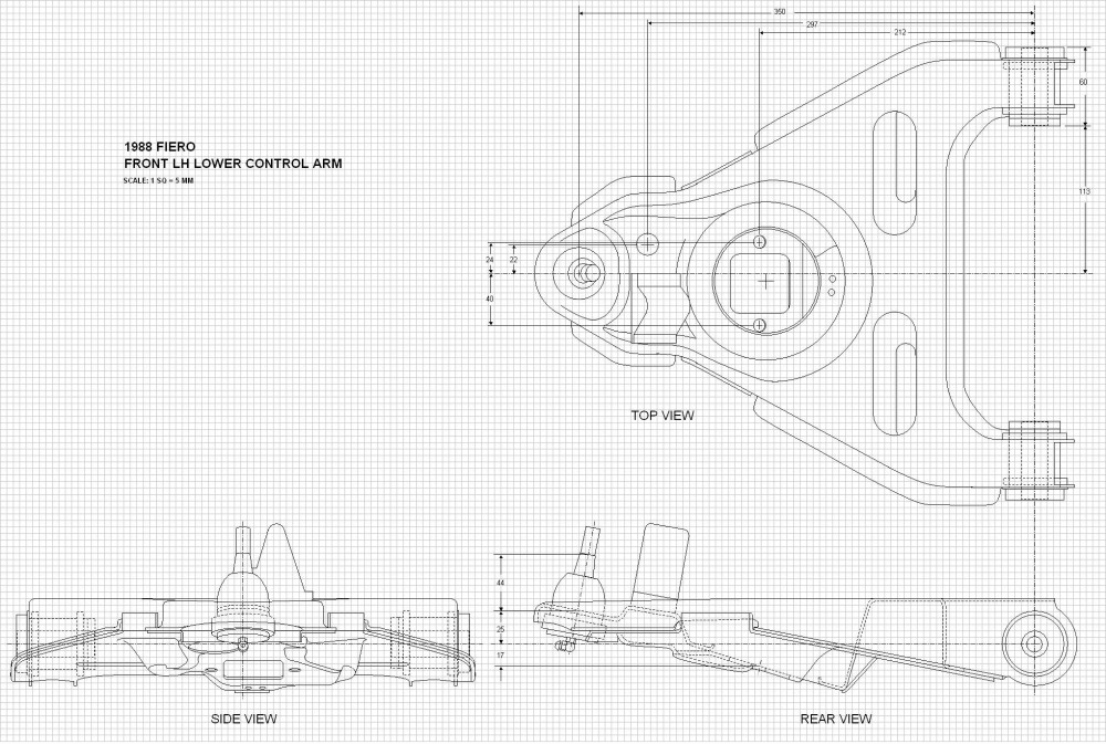


 But I rather expected this since there are so many hundreds of measurements that I was bound to make a mistake or two. Piecing the parts together is sort of like a sanity check... if things don't fit, then there's obviously an error.
 Here is where having done these in a CAD program would've made things exponentially easier. I can tell you right now that the jounce and rebound drawings later on are going to be stick figures, not illustrations like I did for the rear suspension! (Edit: updated drawing to Version 2)

 For those of you following this thread and downloading the drawings, you'll want to update your files with new pictures of the tie rod above, to which I've added the degrees of motion to the side view (you'll note that it's annotated Version 2). Also, I noticed several errors in the original drawing above titled 1988 Fiero Front Suspension LH Side View so I corrected them and annotated it Version 2 as well. The errors consisted of miscalculated front cradle mounting height and the ground clearance to the bottom of the cradle. As well, I noticed that I hadn't completely drawn the lower profile of the lower control arm which further reduces the overall ground clearance. If I discover any other errors I'll just keep changing the Version number and call attention to the changes in future posts. Likewise, if anyone sees any errors, please do not hesistate to let me know so I can correct them.


 (Edit: I have now corrected the tables for the front and rear suspension coordinates above, so they now contain correct data).


 I'm open to anyone else's interpretation or additional noteworthy aspects I've missed. I've formatted the graphs to be somewhat more intuitive than the ones cranked out by the Lotus software, by placing jounce and rebound on the vertical axes (as though you were viewing the wheel moving up and down) with +80 mm representing the wheel having moved upwards in jounce, and -80 mm moving downwards in rebound. The suspension characteristic being studied in any given graph is then plotted along the X (horizontal) axis.


