Blooze...What can I say...Awesome stuff...I have the Herb Adams book and I know what you mean...Not the greatest. A book I would recomend if you can get your hands on it is "Race Car Vehicle Dynamics" by Milliken and Milliken. It's an SAE book. Bill and Doug Milliken invented the science of vehicle dynamics while researching the Corvair issues for GM, then taking the research a step further to dominate CAN AM racing. The history makes it a great read.
What are the differences in geometry when changing the lower ball joints (1/2" or 1" drop) on the front suspension when compared to stock? Thought I would ask...
[This message has been edited by Lonster (edited 03-13-2011).]
Must be working on something big! Been a few days since an update.
EDIT:
Say, I'm about to tear into one of my alternators and starters to perform a rebuild like you documented in this thread. (Never would've thought about attempting it before I saw your posts!) I was just wondering if you used a special paint for the parts you painted on them?
Thanks and keep up the good work!
[This message has been edited by aeffertz (edited 03-17-2011).]
Ha! Well you're right about it being something big... it's just not car related Been up to my eyeballs (and nose hairs) in stripping the 200 year old plaster and lat walls from the last room in our house that needed renovation. I'll be back on the project car soon though. (oops my wife just reminded me I'm spending quality time with her while we renovate together... I suppose that's not so bad.)
Thanks for the reference to the Miliken & Miliken books there ccfiero and RCR. I’ll be ordering it.
As for Lonster, those lowering ball joints on the front-end are going to change the camber curve since the lower, longer arm remains parallel to the ground, but the upper, shorter control arm will ride with a more upward angle at the ball joint end, effectively making it shorter, and pulling the upper end of the knuckle inboard slightly. You’d probably have to counter this increase in static camber by slotting the upper ball joints to move the top of the knuckle outboard again. That would solve the “at-rest” issue, but dynamically you would also get a faster rate of camber change as you compressed the suspension than would otherwise be the case with normal ball joints. That would happen because the upper arm is already part way up it’s arc of movement. At least the camber will change in the correct direction so that’s not bad, but I can’t say if it would perform better or worse than stock. There would be increased bending stresses on the lower control arm where the ball joint is pressed into it. That’s an area that should be monitored for cracks occasionally if you go with the tall joints.
Well, I’m stuck in the middle of some home renos and immediately after that, I’ve got to change a clutch in a customer’s ’88 GT, and do some suspension work on the father-in-law’s MGB. That means I’ve got precious little time to devote to this thread at the moment. So, in the interests of keeping this thread from falling off the front page, I’ve decided to go a little out of sequence and mix things up a bit.
As super-interesting as suspension drawings can be I’m going to buy some time, go out on a limb, and post some front suspension pictures hoping you guys can keep what’s-what straight in your heads. This should buy me enough time to eek in a moment here and there between jobs to work on the 6” increased track-width drawings for the new rear and maybe get on with the cradle fabrication. So without further ado…
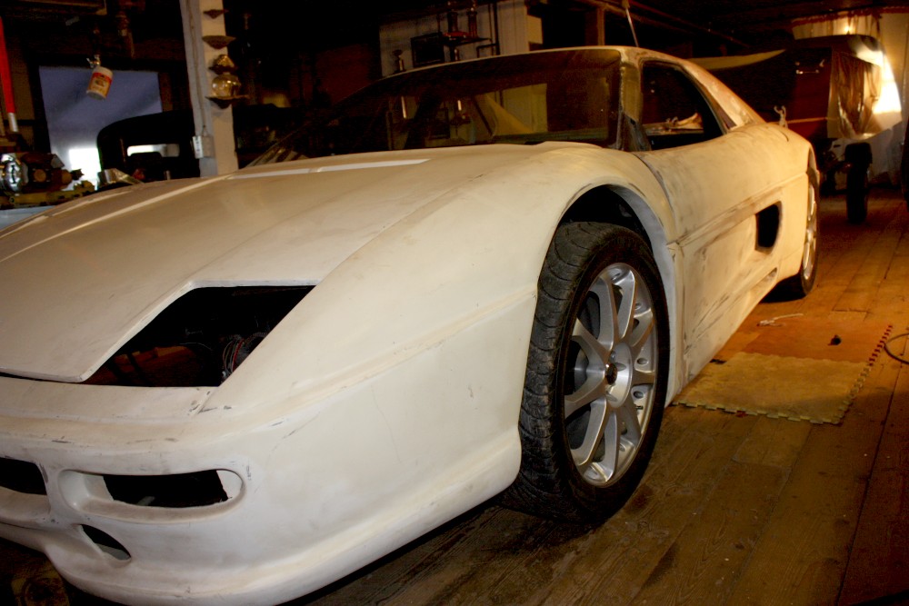
For those of you who’ve ever considered buying some of HT Motorsports stuff, these next couple posts are for you. I did a fair bit of research before I bought the increased track-width suspensions fore and aft, and so far, I can tell you I’m not disappointed. I knew that wheel spacers on the front just weren’t going to be in the cards because of the effects they have on everything from increasing scrub radius, to bending stresses on the bearings. Spacers that are up to an inch thick probably don’t change much, but here’s what I had to contend with…
There just wasn’t any way that I was putting 3” spacers on the front. So I removed the wheels and blocked up the car with the lower control arms level to the ground. Then, I placed several different wheels with known widths and offsets in the fender well where I wanted the wheel to sit, and carefully measured the gap from the back of the wheel to the mounting surface on the brake rotor. Here I was using an Audi TT wheel.
This then allowed me to calculate just how long my control arms should be for any given wheel width and offset. I settled on the combination of the longest possible arms and the wheels with the greatest positive offset, namely 3” longer arms, and 7” width front wheels with +48 mm offset. (I can tell you now that there aren’t too many wheel options out there with those dimensions and a 5 X 100 mm bolt circle, so some of you may be able to guess which wheels I’ll be getting
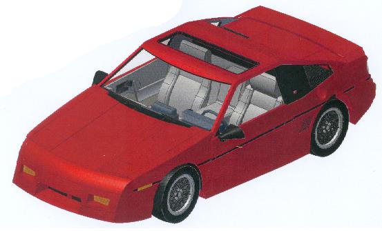
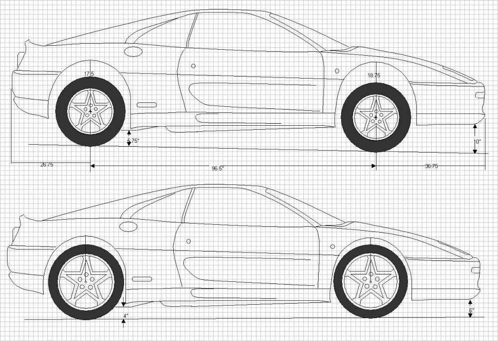
The other thing this test fitting allowed me to do was measure the gap between the top of the tire and the bottom of the fender lip to determine just how much of a drop I would need to fill the wheel wells with the tires. I also played around with some scale drawings I had made to see what the effect of different overall diameter wheels would be in combination with different suspension drops needed to take as much of the guessing out of the equation. Here’s a sample among many I did. The top car is with 16” wheels and 24.5” tall tires without any dropping, and the bottom car is with 18” wheels and 25.25” tall tires, plus a 3” drop IIRC.
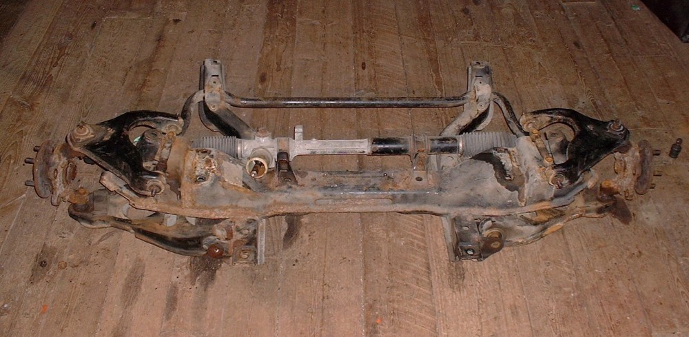
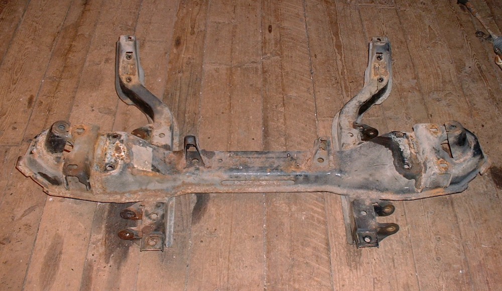
To get the right drop and wheel well fill on the front end, I decided to get HT Motorsports 1.5” drop spindles (since that’s the max they currently make), and fine-tune the rest with adjustable coilovers. (At the moment, I expect to buy 225/45/17's for the front since they have a 25" diameter, but this isn't cast in stone yet.) With my HT shopping list in hand, I ordered the front end components and while I waited, removed and took apart the OEM front cross member. Here it is in all its glorious Canadian weathering (less the springs). This is the view from the driver’s seat:
Here’s another view as seen from the front quarter of the car:
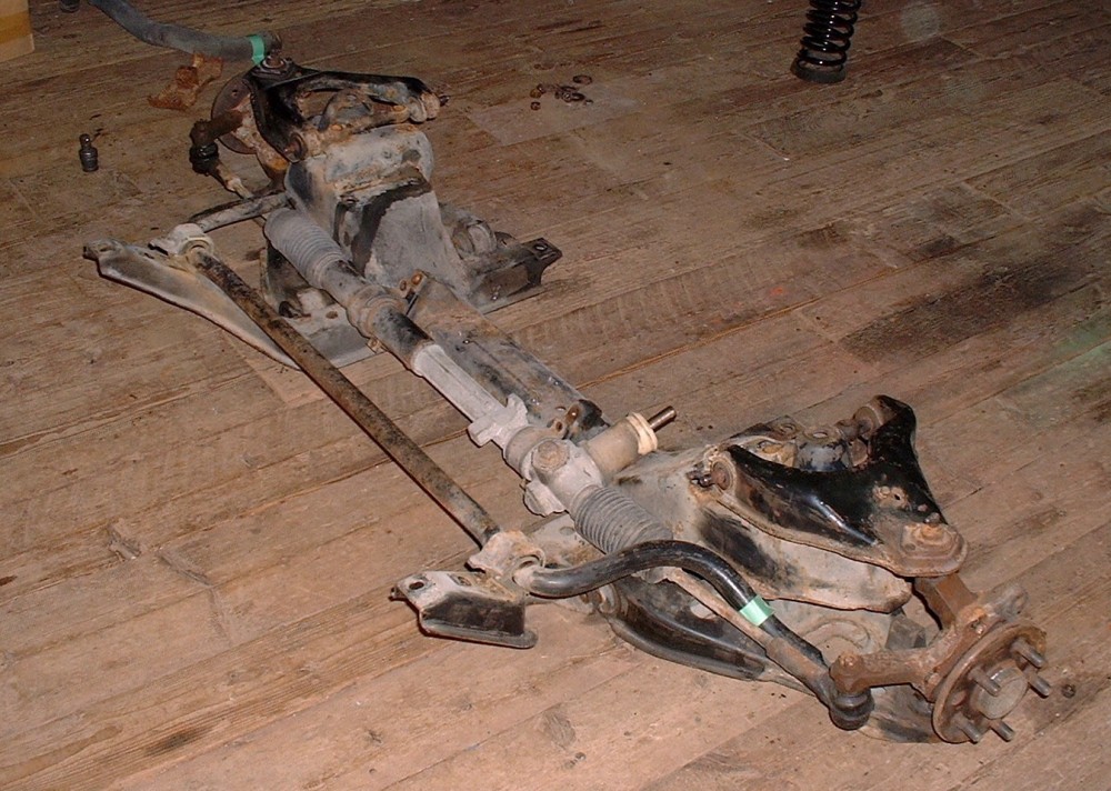
I spent a couple hours getting the suspension components off the cross member, running into the usual problems of seized bushing sleeves, and shearing bolts etc, but here is what I was ultimately after since everything else is going to be replaced:
Next stop: the sand blasting booth (the great outdoors), and the painting booth (the great outdoors)… stay tuned.
Very nice work Blooze! I'll be watching your suspension progress. I've already decided to cross drill my rear rotors after seeing your posts on the previous page.
I modeled up the 88 rear suspension based on Bloozberry's terrific drawings and work that I've done previously and have done some motion analysis and made some low rez animations. Next time around I'll set the resolution higher and just wait on the rendering.
If you watch it a few times you can see how the wheel toes in as it travels up and down.
Given this a tri-link stut style, there's not much camber gain, but you can help it out by raising the lower links location on the subframe to keep it negative as long as possible.
I can do one with your long links and see what it looks like.
------------------ yellow 88 GT, not stock white 88 notchie, 4 banger
Yep, 3" per side, but remember that the strut remains at the same location and angle... the gap between the newly located knuckle and the bottom of the strut is taken up by a solid spacer that you'll have to model either as part of the lower strut or top of the knuckle.
[This message has been edited by Bloozberry (edited 03-22-2011).]
Here is the setup, the animations start at ride height, in this instance, the bottom of frame is 5.75" off the ground. Which in most fieros means it's lowered. The wheel/tire combo is 17x9 25mm offset, 255/40/17 tire. I added 3 inches to the fixed length rear toe link and adjusted the others to get a half decent alignment to start with.
I did come across one measurement that looked out of place, the height of the attachment point of the strut piston, is about 5 inches lower then what is on your drawing. If I use your number, my strut does not have enough travel in droop. (Strut is model on a worn out Monroe unit)
As you can see the toe links are at an rising angle to start with, which takes away negative camber as the wheel moves up. For more negative camber gain, the toe links should be angled down at ride height.
It looks like the 3 inch addition acts pretty normal,
------------------ yellow 88 GT, not stock white 88 notchie, 4 banger
I suspect there's something wrong with the numbers you've used on one of the animations since there should be no difference in the angle of the toe links if the only variable was their length. Did you change tire diameters between the first and second animation? Or change the ride height? Stock ride height IIRC is 6" (plus or minus) as taken at the bottom edge of the cradle. I'm curious why the height of the strut to mount is so much further off too. Must be something we're missing.
Oh yes, there could be a lot of differences, one of them that crops up is all the links must be constrained as ball joints, and locating the pivot point in a rubber bushing adds a certain amount of guessing, but your right, theoretically the links should be parallel, in real life I've seen them a little like the animation. As for the strut location, what do you measure in a strait line from the center of the hole in the strut tower to the axis of the front toe link on the sub frame? I can match that and try again.
I been using the 5.75" as a chassis height because that was what it was before I took the car apart. I'm not sure if in the real world the bottom surface of the sub frame is actually parrallel to the the ground, isn't there a bit of a rake?
I did change the wheel/tire, the first one was 17x10.5 with a 285/40.
------------------ yellow 88 GT, not stock white 88 notchie, 4 banger
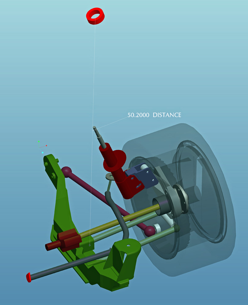
The distance from the inboard axis of the lateral links to the center of the top strut bushing (which is the effective upper pivot point of the strut), as viewed from the rear of the cradle in a straight line, is 1275 mm (50.2"). You shouldn't use the hole in the strut tower since the bushing is further down by an inch or two.
The cradle bottom, at stock ride height is parallel to the ground... no rake fore or aft.
By grabing the cursor and slowing down the animation it appears to me in both the side view and the lateral view, that the axle will interfere with the engine cradle when the suspension is in full droop
It's just the angle the drawings are seen from. You have to keep in mind that on the driver's side, the inboard end of the axle (where it crosses over the dradle side rail) is kept away from the cradle by the CV joint being mounted a fixed distance away from the cradle. The joint allows the outboard end of the axle to droop below the cradle as seen from the side view, but the outboard end of the axle is much further away from the cradle.
On the passenger side, the long axle does get closer to the cradle because the CV joint is much further inboard so there's more relative movement between the axle and the cradle where the axle crosses over the cradle side rail. But again, it clears in the stock configuration and longer lateral links will only improve upon this clearance. In my case, I'm also using a jackshaft to move the passenger side CV joint outboard.
Whoa whoa whoa!!! There is way too much engineering going on in here. This is a kit car. All you need to know is how to mix bondo and how to use sheet metal screws.
We have discrepancy in dims. I've set the upper strut pivot point (red donut) at 50.2" The shown dim is the from the upper strut pivot to the center of the front lower link hole. I may be wrong, but I don't think the top of the strut is two wheel diameters off the ground.
------------------ yellow 88 GT, not stock white 88 notchie, 4 banger
Yep... for two reasons... the first is that I thought you meant the distance on the diagonal, ie from the outboard axis of the lateral links where they are attached to the knuckle, up to the strut bushing; and second: I accidentally used the wrong scaling factor 20:1 instead of 10:1 when I gave you the 50.2" figure.
So, now that I know you want the distance in "up" plane (the green plane in your last rendering), the 50.2" number should be 595 mm (23.4").
Great 3D drawing by the way. Because there's the potential for miscommunication between us and therefore numerous trial and error drawings, if you don't mind, I'd like to sort out any other iterations of the suspension movements in PM's rather than directly in the thread there ccfiero. That way we won't post misleading or incorrect info. I really do appreciate the work you've done but I'd like to keep the actual build thread as clean as possible.
For those of you who found the 3D animations as entertaining as I did, CCFiero's sent me some more of them with the 3" longer control arms for me to look at before he posts them, but I haven't had a chance yet. As cool as they are, I'll still have to go through my own exercise to determine the best possible location of the lateral links height-wise, and cross car width-wise, plus whether I should increase the angle on the trailing links to improve anti-squat, and raise the upper strut mounts to get more travel.
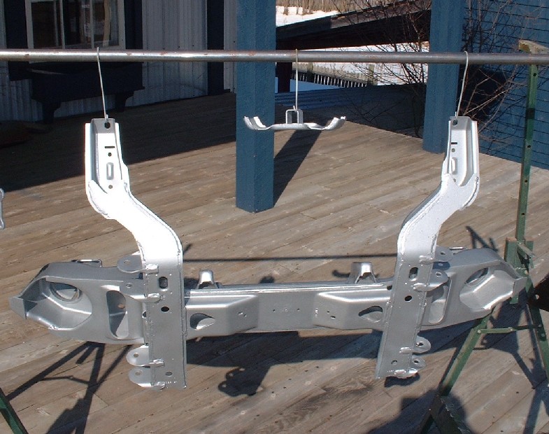
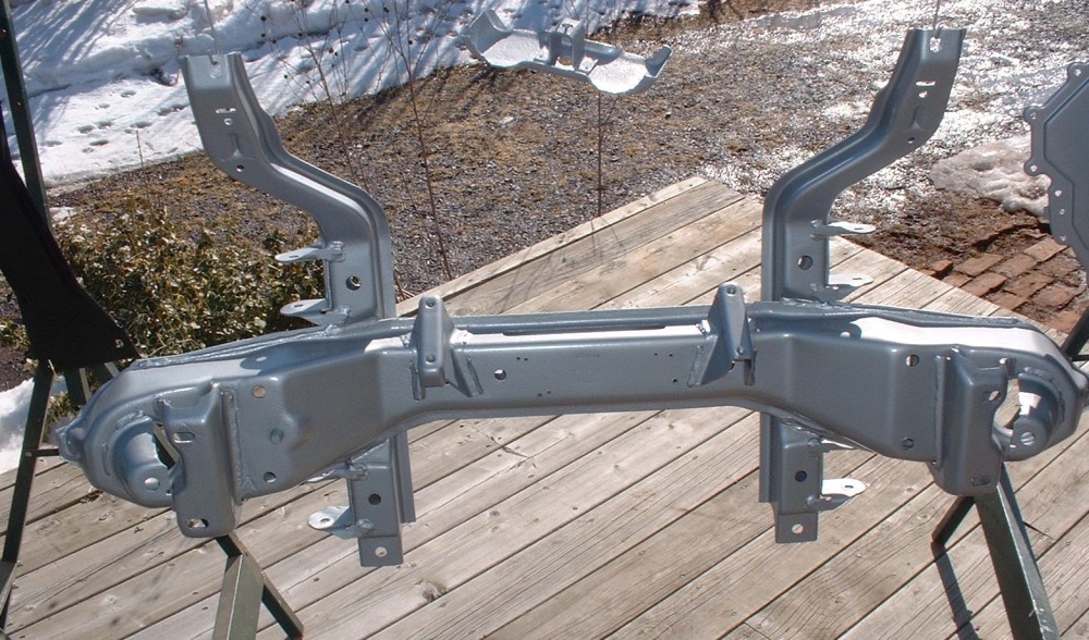
For now, it's back to the front suspension make-over. It’s amazing how a good sandblaster can take a painstaking, backbreaking, four-hour crappy task with a wire wheel on an angle grinder, and turn it into a joy to do. It took me less than half an hour and two $10 bags of crushed glass to strip the old paint and rust out of every pore, nook, and cranny of the front cross member. My compressor just can't handle the bigger jobs, so a friend of mine who owns a top-notch paint shop lets me do the big parts out-back at his shop where he’s got the right set up. Once stripped, I don’t like leaving parts sitting around too long so the shop primed it with an epoxy primer just as soon as it was done. A couple hours later it was home and painted in the final color.
I chose silver because I wanted a different color than the bottom of the car (which will be black), and a light color makes it look less heavy and massive. I know, I know, few people will ever see the bottom of the car, but I want those who do to see right away that this was a ground-up restoration. I find that if everything gets painted black, after a year or two it takes a close look to tell whether it was redone or not. I’d rather it stand out if someone actually takes the time to look under the car.
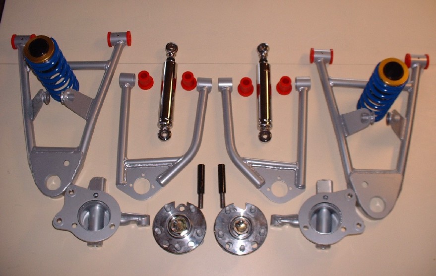
While I was doing this, a big package arrived in the mail. All the front end parts I ordered from HT were delivered, all nicely packaged up in bubble wrap and foam peanuts (I hate peanuts). Look at all these purdy pieces:
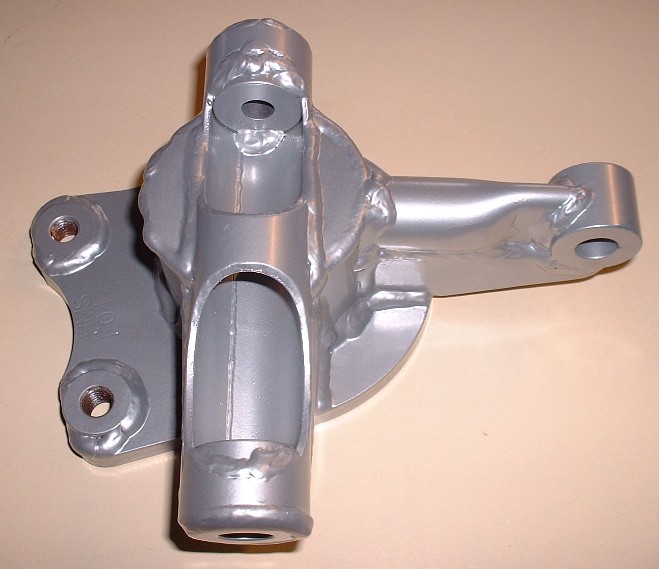
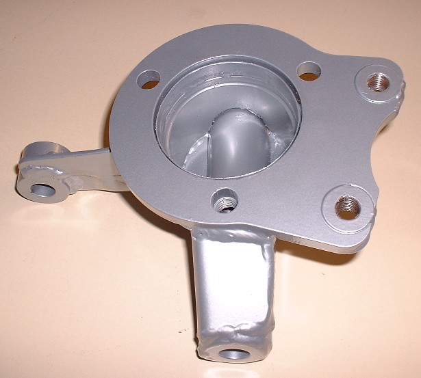
I’ll hone in on each piece separately to give you a better look, and to stretch out the few remaining photos I have before I’ll have to get back to actually working on the car. The most intricate pieces are the drop spindles. There’s a lot of work that went in to these pieces so I can understand the premium price tag better now.
They’ve been ingeniously designed to do away with the OEM ’88 Fiero-specific front bearing assemblies and made to accept the far more common and inexpensive Fiero rear bearing assemblies.
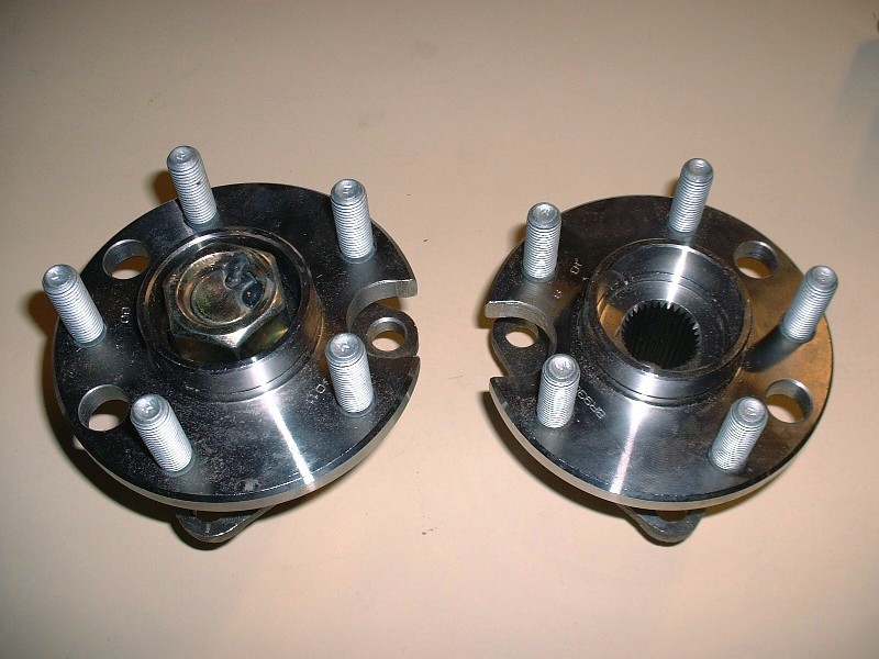
Because the rear bearing assemblies were originally designed for an axle and axle nut to hold the bearing halves together, these bearings are modified with a large bolt as a substitute for the axle. On the left is the modified bearing and on the right, a stock bearing assembly. Note that the large nut has been spot welded to keep it from ever backing off.
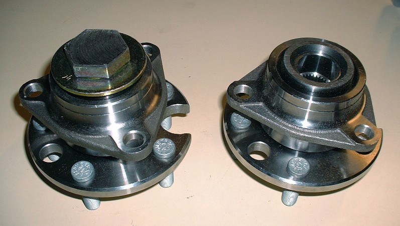
Here’s the rear view of the same pair as above. To solve clearance issues with the inside depth of the drop spindle, the head of the large bolt was machined down somewhat.
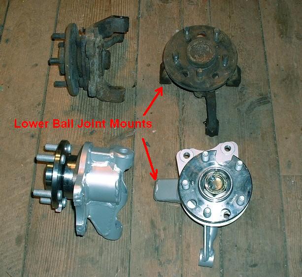
Finally, here’s what the spindle and bearings look like when assembled as compared to the OEM parts. The 1.5” drop is clearly obvious when you compare the two left-most knuckles in the photo. Notice how much more of the lower ball joint mount extends beyond the diameter of the wheel flange on the new knuckle as compared to the OEM one. (Well, actually, the ball joint mount is in the same location, it’s the spindle that’s been raised making the mount look longer.) That should take care of some of that ugly gap between the top of the tires and the wheel well lip.
If you haven't figured out how, Wierd Al knows a good way to get rid of those peanuts you hate so much at the end of this song. http://www.youtube.com/watch?v=y4sALru9IJk
Originally posted by Bloozberry: I chose silver because I wanted a different color than the bottom of the car (which will be black), and a light color makes it look less heavy and massive. I know, I know, few people will ever see the bottom of the car, but I want those who do to see right away that this was a ground-up restoration. I find that if everything gets painted black, after a year or two it takes a close look to tell whether it was redone or not. I’d rather it stand out if someone actually takes the time to look under the car.
quote
Originally posted by RCR: Looks great Blooze...I'm probably going silver on my front conversion, too, although I may play with some translucent powders. Bob
Some similar tastes here , I wanted a contrast to the black frame too.
Wow… time flies when you’re busy! I see that my thread is getting closer to the bottom of the first page so I guess it’s time for another update. Thanks guys for your comments. I'm a huge Doors fan Reallybig but I had never seen Wierd Al's take on anything from them. If you see an eBay ad for styrofoam peanuts anytime soon, you can rest assured they're from me! As for Fiero2M8, I've been keeping a close eye on your amazing build too. I feel like my suspension is the Chevette equivalent to your Cadillac version though, so I try not to look too often otherwise I'll either get discouraged, or end up like Cptsnoopy and risk having even more money disappear from my thinning wallet.
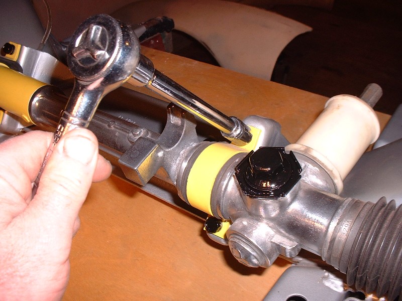
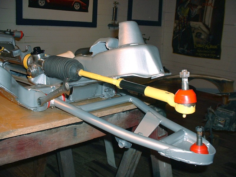
Continuing on with the front suspension build-up, the first thing I decided to attach back on the front crossmember was the tidied up steering rack. I checked it over for worn inner tie rods and the rack bushing, but the clearances seemed pretty much like new. So I blasted everything with crushed glass, polished a few highlights on the rack tube, and primed and painted the steel parts. Once it was ready, four simple bolts torqued to 20 lbft hold it to the crossmember:
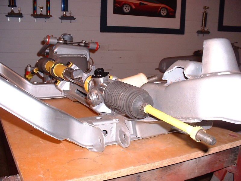
I think the guys that put in power assisted racks are amazing. It would be cool to do that too, but not on this first go around. I am on some sort of budget. Now those of you thinking ahead might be asking yourselves “How the heck is he going to connect those stock length outer tie rods up to his 3” extended control arms?”
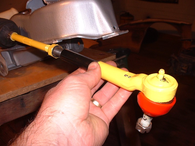
The answer to that is quite simple actually. A 3” tie rod extension tube with male threads on one end and female on the other is all that’s needed. This method keeps the inner and outer tie rod pivot points in the same spatial orientation relative to the upper and lower control arm pivots on the inboard side of things, and the upper and lower ball joints on the outboard side. I just hope that when I go to get this thing inspected (mandatory provincial inspection every two years) that they don’t raise their eyebrows too high when they see this. Maybe I should paint them yellow to blend in a little more.
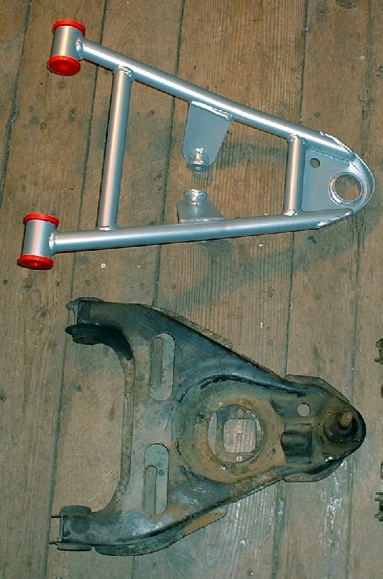
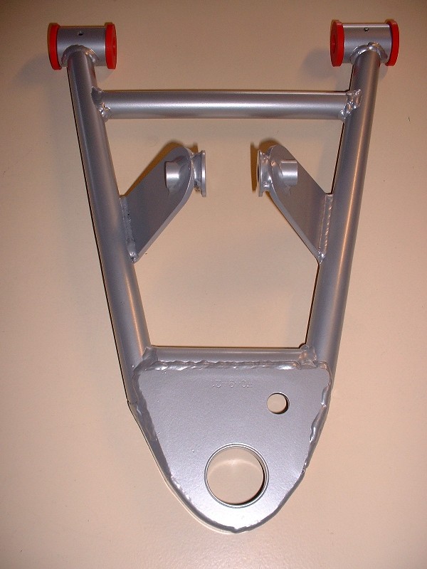
So next up is installing the lower control arms. Here’s what the old and the new look like side by each. The tubular arms look soooo much cleaner than the stamped steel ones. I just hope they’re as rigid or even more so than the OEM ones.
Notice how the lower shock mount ears extend quite significantly below the arm. This reduces ground clearance somewhat over uneven roads compared to the OEM ones but allows the use of the adjustable shocks. Aren’t they purrrrdy?
Getting these lower arms in the crossmember pockets with the urethane bushings takes a little poly grease and elbow grease. They certainly are a tight fit, which I suppose is better than having them flop around. The two nuts on the pivot bolts get torqued to 37 lbft + 270 degrees. (I’m only mocking things up at this point so I’m leaving things loose for now.)
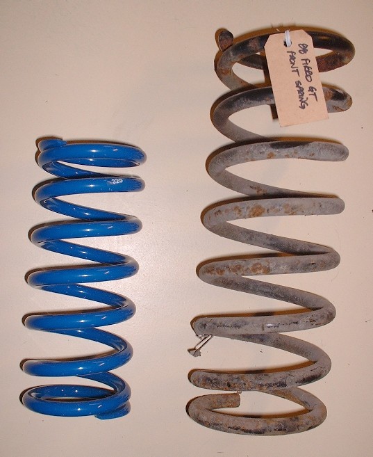
Next up is the installation of the shocks and springs. Here’s a close up of the my new 325 lb/in front springs vs the old OEM springs. I hope I didn’t make a mistake and order them too stiff. Only time will tell.
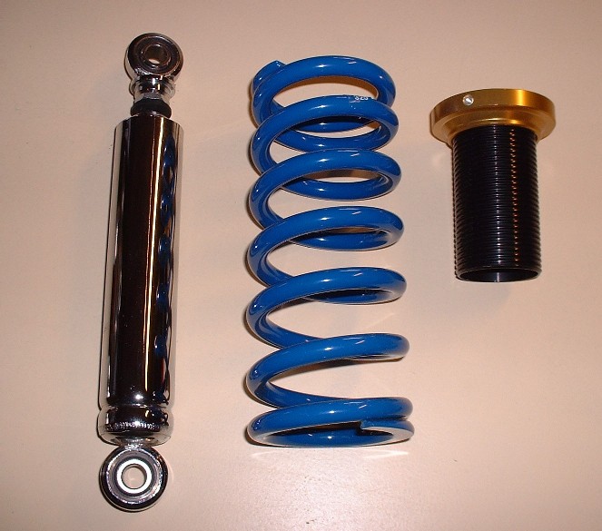
Here are the rest of the pieces that make up the coil-over shock. I got the Carerra chromed shocks with my suspension kit, not that anyone will see much of them once they get the adjustable tubes installed. The only thing missing from this photo is the upper spring seat. The springs are considerably smaller in diameter than the stock springs so HT Motorsports provide a heavy duty collar that serves as the new spring seat. I'll post a picture of them later.
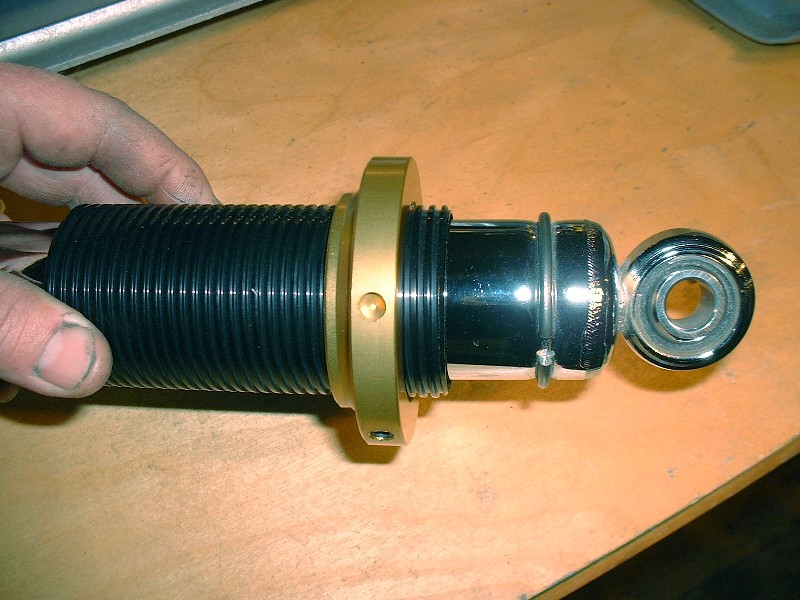
In order to keep the threaded adjuster tube from sliding off the end of the shock body, a powerful circ-clip is installed in the lower groove of the shock. Installing those clips nearly had me pitching the whole thing into the pond. It had to be one of the most frustrating aspects of this build so far… no kidding. I bent two pairs of circ-clip pliers, searched half a dozen times for the clips on the floor after they went flying every direction imaginable, pinched my finger tips, you name it… it happened.
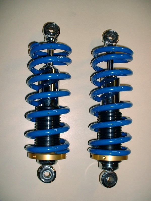
Once they were finally on, I could finish building up the coil-overs… which was just a matter of slipping the threaded tubes on and then the springs. This was one of those jobs you'd schedule 5 minutes to do and spend one hour. See what I meant by how little the chrome body of the shock shows? At least I’ll know they’re there.
Thanks for the tip ccfiero… drain holes are now on the list of things to do! Thanks too for your input Aaron. I want the car to ride low, but our secondary roads here in Nova Scotia are pretty pathetic. I think 325 will be a good compromise between being too stiff and bottoming out especially given the added leverage of the longer arms.
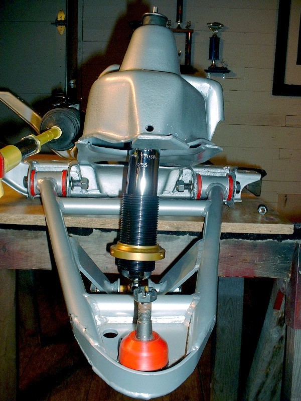
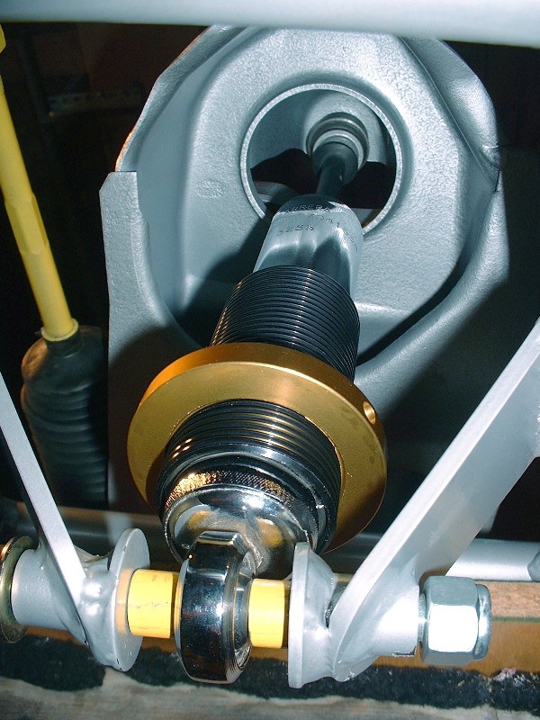
Now, on to more pictures. Once I had the springs built up, I tried them on but without any weight on the cross-member the lower control arms were being forced all the way down. Since I’m only mocking things up at this time, I removed the springs and installed just the shocks for now. It’s pretty straightforward, a bolt through the lower control arm mounts and the hemispherical joint at the bottom of the shock, then feed the top of the shock up through the hole in the upper spring pocket on the cross-member. There’s a pair of poly bushings on the top of the shock shaft similar to the ones on the sway bar end links:
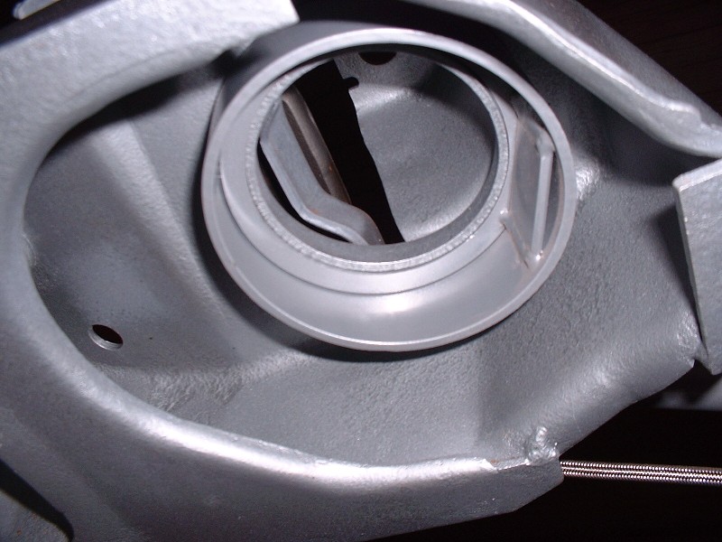
I wanted to add this next photo for two reasons. The first is that it shows the stock spring seat in the upper part of the cross-member. With these new springs that are shorter and smaller in diameter than the stock ones, there’s a heavy duty collar that comes with the HT Motorsports parts that adapts the new spring to the OEM upper spring seat. I’ll add a picture of it later since I don’t have one ready right now.
The second reason was to point out the yellow spacers I had to fabricate from steel tubing to center the bottom of the shock on the lower mounting bolt. The space between the mounting ears welded to the lower control arm is way too wide for the width of the heim-joint at the bottom of the shock. It’s a simple fix, but one that I feel should have been included in the kit from HT.
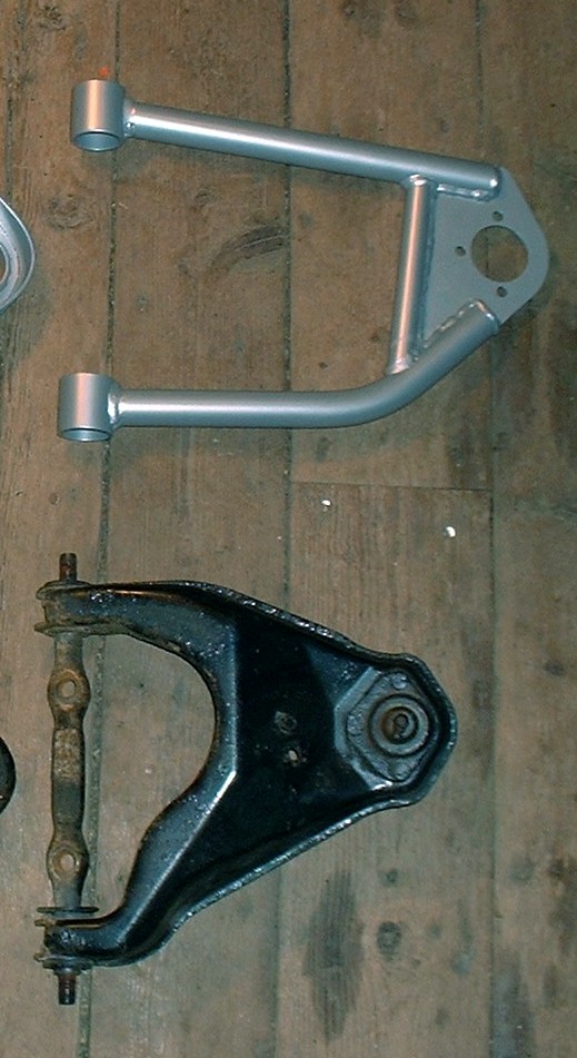
With the shock installed, the next step is adding the upper control arm. Here is a picture of the OEM and 3” longer one for comparison’s sake:
Installing the upper control arm is a breeze, just two bolts through the upper pivot bolt. Getting to that point is a little harder though. HT doesn't provide the upper control arm pivot bolt so you have to re-use your stock one, and that can be a PITA to take off. To remove it from the stock arm, you have to dig/burn/press out the stock rubber bushings from both sides of the control arm before the pivot bolt can be slid out. The usual problems of bushing sleeves seized to the pivot bolt turn what should be a simple ten minute procedure into an hour long drama complete with swearing, flying tools, and either burnt, cut, or pinched skin.
The front-end caster and camber alignment depends on where you tighten the two bolts through the elongated holes in the top of the cross-member though. The nuts that the bolts thread into aren’t captured to the underside of the spring seat unfortunately. Instead they’re welded together onto a thin piece of sheet metal that’s got to be held in place while tightening the bolts. That generally goes OK, but the metal is notorious for twisting out of shape if you ever decide to loosen the bolts.
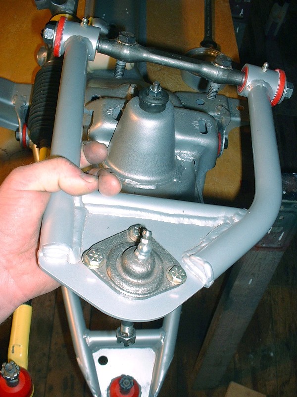
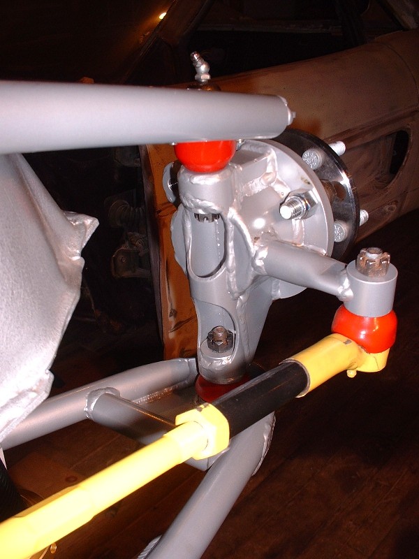
The next piece of the puzzle is the knuckle assembly. It’s only held onto the spindly little control arms by the upper and lower ball joints and the outer tie rod. In this view you can clearly see the front to rear tilt of the upper control arm. This property of the arm is what determines the amount of anti-dive.
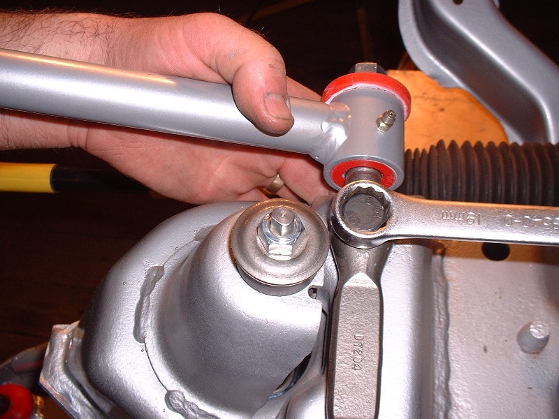
HT designed a generous amount of accessibility to the upper and lower ball joint nuts through large windows cut out of the backside of the tubular uprights:
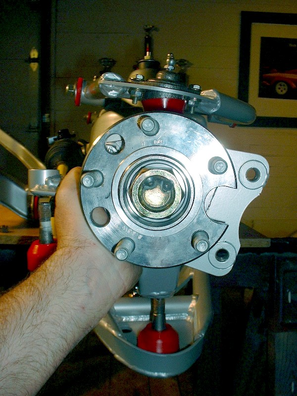
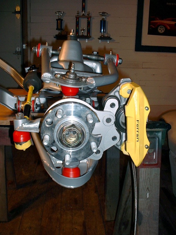
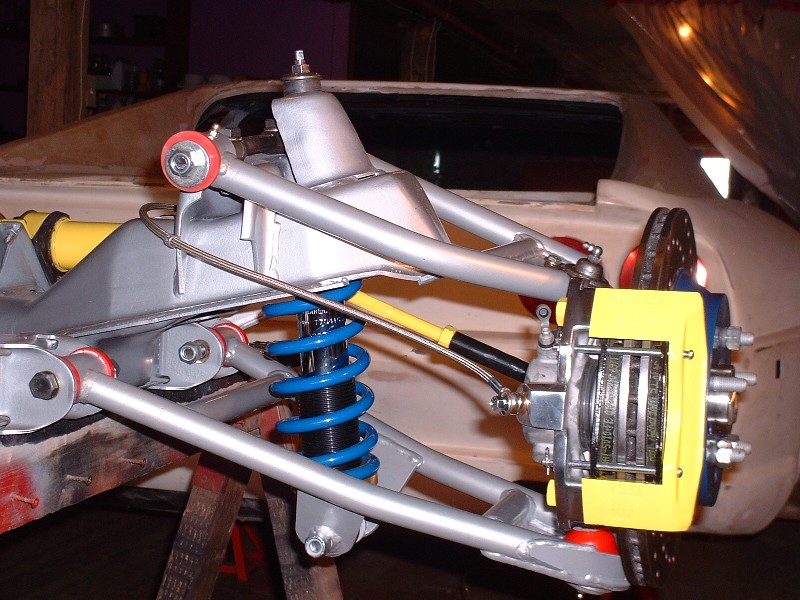
And here’s the street-side view of the installed knuckle assembly. On the one hand, the whole thing just seems impossibly weak to do the job it does, but on the other, it looks decidedly race-like… low weight, small visual mass, and a hanging-way-out-there look. Heavy-weight brakes will more than compensate for all that low weight stuff soon enough though.
Thanks fierogt28 and RWDPLZ (although I'm not so sure calling me nuts was a compliment ) For Fierobsessed, I've checked my lower control arms for interference with the brake rotors and indeed they contact each other, although the condition may only exist at the extreme end of the suspension travel in rebound. I'll have to look more closely at this and post some findings the next time.
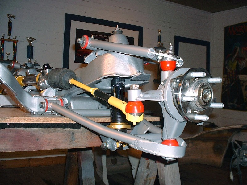
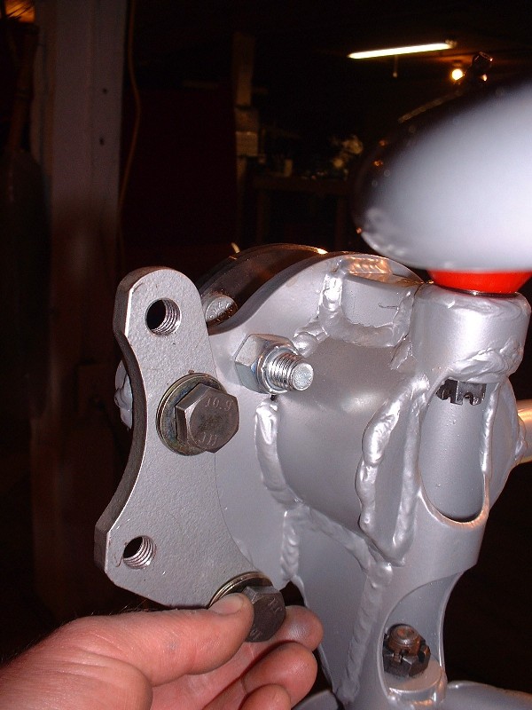
For this post, I'm going to finish up the assembly of the front crossmember with the addition of the brakes. As with the rear suspension, I opted for the 12" C4 Corvette rotors and stock '88 Fiero calipers. That meant simply bolting on the Fiero Addictions brake caliper adapter onto the HT knuckle...
... and then bolting the caliper onto the adapter using the stock caliper bolts through the sliders. As with the rear, I discovered that the rotors can be installed and removed from the hub flange with the caliper installed.
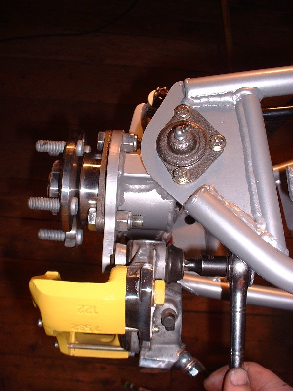
Here's the street-side view of installed caliper... I'll go along with this set-up for now and maybe someday I'll beg the Reprovisioning-Fairy for the four piston caliper upgrade.
With the caliper installed, it was a simple matter of slipping on the rotors at a bit of an angle, sticking on a couple lug nuts to hold them square to the hub, and installing the brake pads in the same manner as the rears were done earlier.
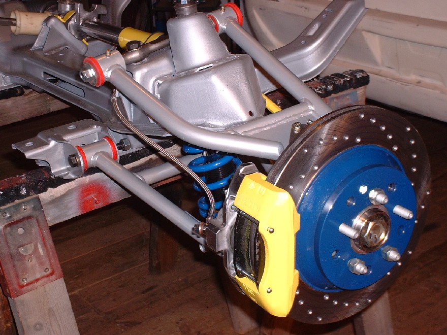
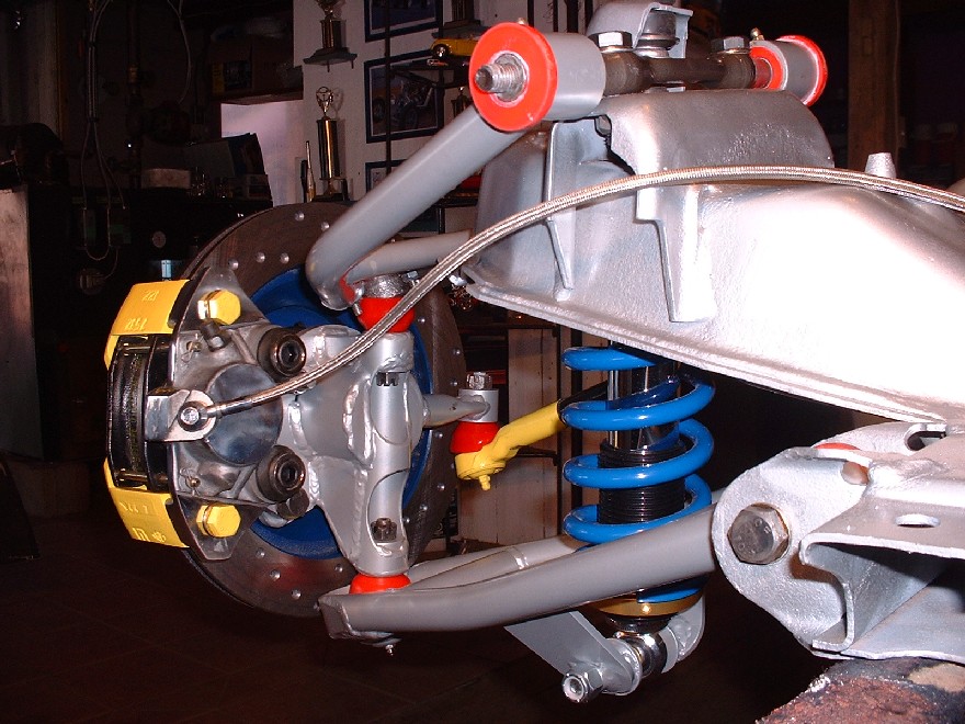
I used stainless braided flex lines to complete the look and for the improved pedal feel. The old rubber lines were too short anyways. Here I've installed the springs to complete the mock-up for the picture, but they force the control arms downward to the max rebound position and make it harder to install the crossmember as a unit back into the car. I'll be taking them off to install the front end later.
And finally, here's an inboard shot to complete all the possible angles anyone could possibly want to see. It's kind of colorful, but in my defence I didn't get to choose the color of the ball joint boots or bushings. I would've gone for lime green
Blooz, your new springs have a smaller diameter than stock - how do they seat at the top?
quote
Originally posted by Bloozberry:
And finally, here's an inboard shot to complete all the possible angles anyone could possibly want to see. It's kind of colorful, but in my defence I didn't get to choose the color of the ball joint boots or bushings. I would've gone for lime green
Blooz, your new springs have a smaller diameter than stock - how do they seat at the top?
Thanks for pointing that out 88GTS... here's the answer:
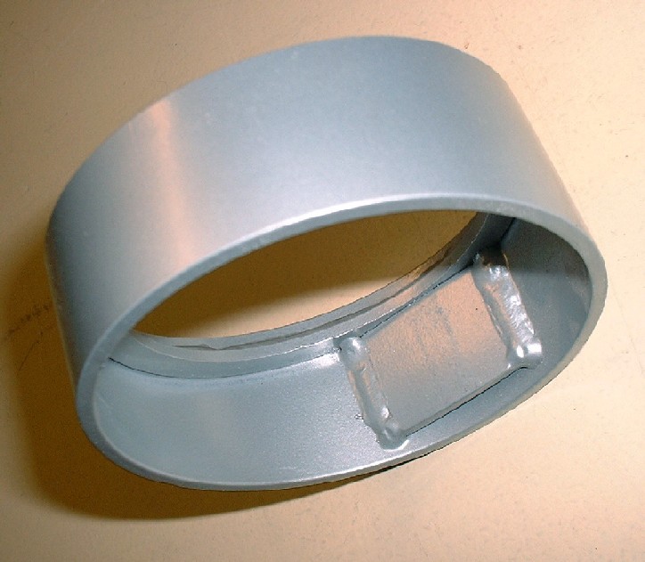
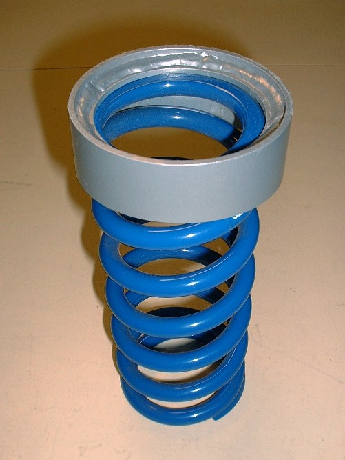
When you order the '88 front coilovers from HT Motorsports, they send along a spring adapter that looks like this. The top-side has a ring welded onto it that makes the ID a bit smaller than the bottom side (ignore the flat tab welded on the ID):
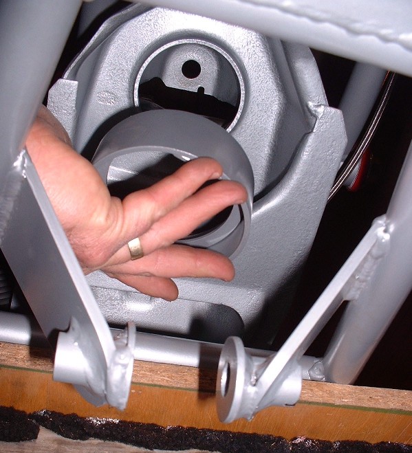
The end of the adapter with the smaller ID fits tightly on the OEM spring collar in the crossmember. The adapter is also wedge-shaped so once you've slipped it up through the spring pocket you also have to orient it so the thinner edge of the adapter is towards the inboard-side of the car. That flat tab welded on the ID is on the wider edge of the adapter, so it's got to go towards the road-side.
In the picture below, the HT spring seat isn't perfectly lined up, but you get the picture. Once it's up there, you peen the OEM spring seat collar over to lock the HT adapter to the crossmember. HT also recommends adding a thick bead of silicone between the top surface of their adapter and the crossmember to make any movement between the two pieces as squeakless (is that a word?) as possible. HT does say that peening isn't absolutely necessary since the spring is always in enough compression to hold the adapter in place. I think I'll weld it into place on mine.
I don't have a picture of the springs installed from the bottom side of the crossmember, but here's how the spring seats inside the adpater.


 Been up to my eyeballs (and nose hairs) in stripping the 200 year old plaster and lat walls from the last room in our house that needed renovation. I'll be back on the project car soon though. (oops my wife just reminded me I'm spending quality time with her while we renovate together... I suppose that's not so bad.)
 I’ll be ordering it.
 That means I’ve got precious little time to devote to this thread at the moment. So, in the interests of keeping this thread from falling off the front page, I’ve decided to go a little out of sequence and mix things up a bit.
 I’m going to buy some time, go out on a limb, and post some front suspension pictures hoping you guys can keep what’s-what straight in your heads. This should buy me enough time to eek in a moment here and there between jobs to work on the 6” increased track-width drawings for the new rear and maybe get on with the cradle fabrication. So without further ado…


 The most intricate pieces are the drop spindles. There’s a lot of work that went in to these pieces so I can understand the premium price tag better now.