Thanks doublec4. You're doing some really interesting stuff too.
quote
Originally posted by doublec4: May I ask where you bought those spherical bearings?
I bought them from Summit Racing, their part number FKB-FKS10.
quote
Originally posted by Insky: One of the main things that may prevent me from pursuing a project like this is liability. Has anyone done any in depth research about what kind of liability a builder may have if they eventually sell the project?
I haven't done any such research, but then again I too believe my case is different from yours as you suggested. Once a provincially authorized professional engineer has completed and accepted the design and construction of my project, that certification is applicable in all three of the Maritime provinces in Canada, and likely would be acceptable to any other provincial jurisdiction across Canada as well. In that sense, I believe my liability would be limited provided that if I ever did sell the car, I were up front about the modifications, had a detailed account of the build process, and got any potential buyer to sign an affidavit acknowledging that he was aware of and accepted the modifications. I would also likely need to specify that the car was being sold "as-is, where-is" which also covers pretty well everything else. That will likely turn off many potential buyers and lower the overall value, but then again, I don't think that anybody going to this depth of modification ever expects to get his money back. If you do venture down this path it's probably best to keep and enjoy the car as long as you can, and expect that it will depreciate like any other car you would otherwise have bought.
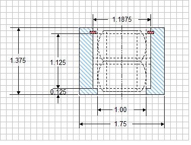
As for a little update, I've got a few more pictures to show off some progress. Today I finally managed to get some time on a friend's metal lathe to make the bell crank hubs. As planned, I started out with a piece of DOM 1.75OD X 1.0" ID structural steel tubing. It was $15 per foot so I bought 12" and cut two sections from it that were 1/4" longer than what I needed. Here's the sketch I used to make the hub, though I had to modify it slightly:
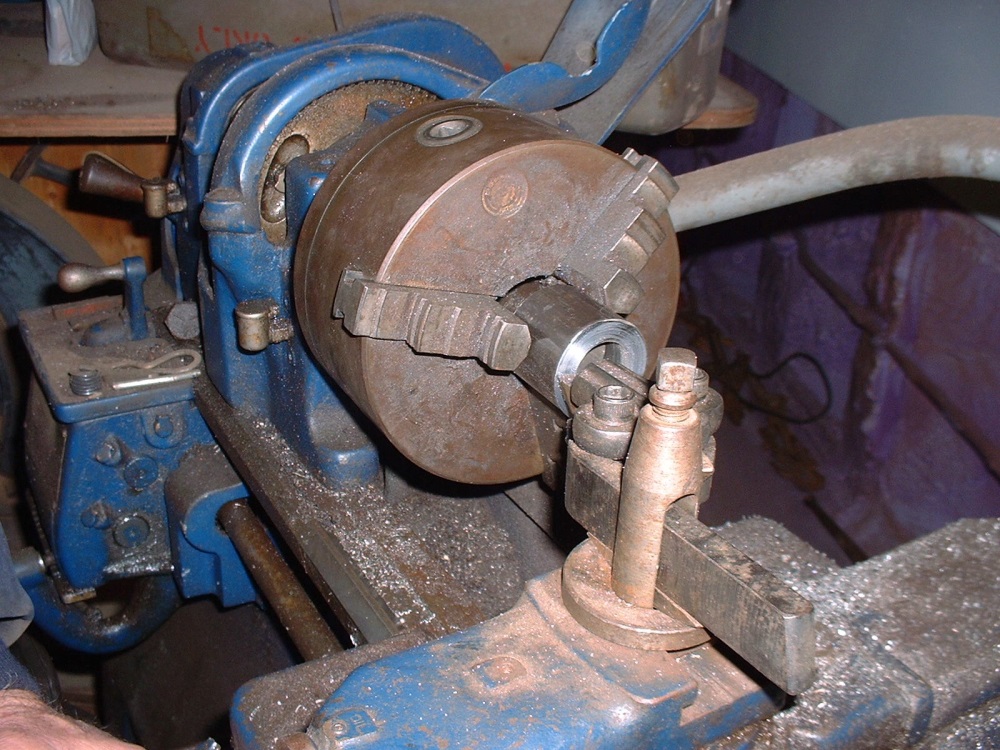
Once I had machined the inside diameter to 1.1875 (1-3/16") leaving a shoulder at one end, I machined a snap ring groove at the correct distance from the shoulder. The only snap rings I could get locally came in increments of 1/8" diameter so needless to say I had to upsize the rings from 1-3/16" in the drawing to 1-1/4". That meant I needed to increase the diameter of the snap ring groove, and the top lip just above the snap ring so that the larger ring would fit down the bore and into the groove. Here's a quick shot showing me squaring one end of a hub after roughly cutting it to length with a cut-off saw.
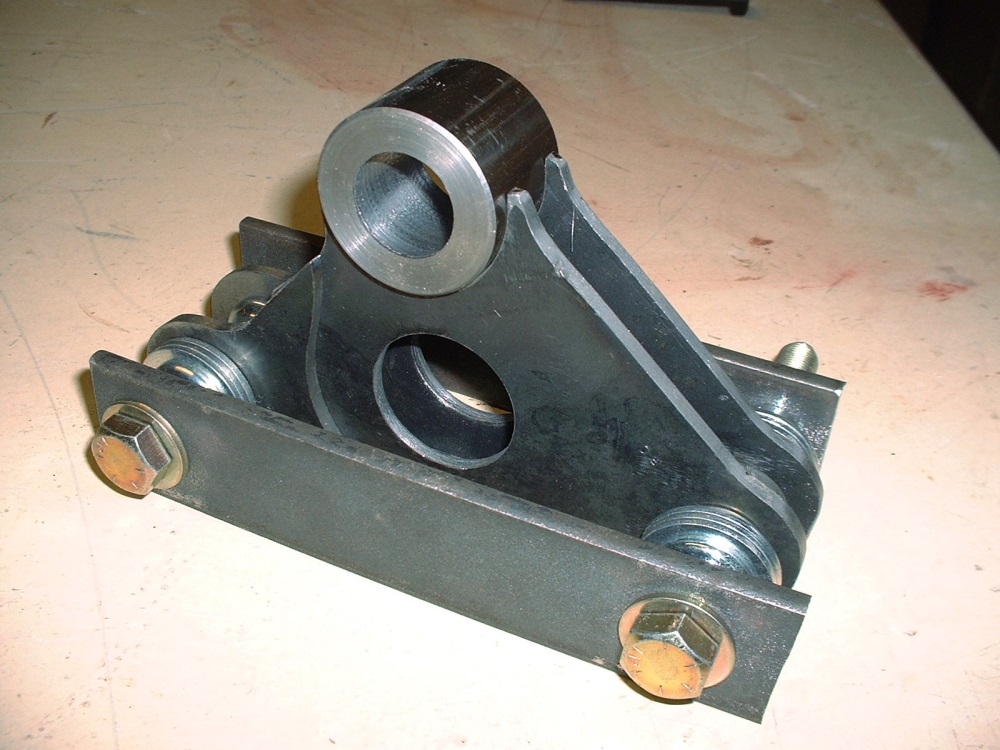
Things went pretty smoothly and although I was aiming for an interference fit between the bearing and the hub, the lathe (or perhaps the operator!) wasn't accurate enough to achieve any better than a finger-tight fit on both hubs. That's OK though since Locktite makes a special type of locking compound for just this sort of scenario. I have a bottle of it in the shop but can't remember the number off hand (604 maybe?). The F-18's use the same compound in their F404 engines to lock some of the axial bearings to their housings so I'm pretty sure it'll do the trick here. Once the inside diameter machining was completed, I shaved off the extra 1/4" I had left on the length, centering the bearings between both ends. Here are the pieces that go into making one bearing hub together with one that's assembled:
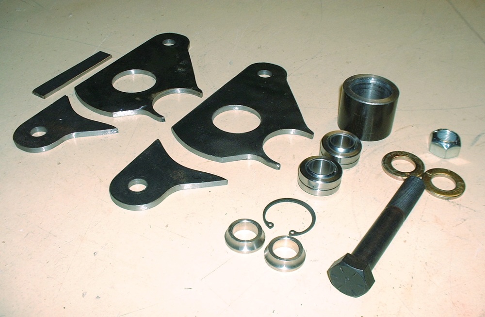
Since the last time I posted I spent some time drilling lightening holes in the bell crank arms, and fine tuning the fit of various pieces, so here's an updated photo of all the parts that go into a single bell crank:
To make sure the end pieces get welded to the main part of each arm at exactly the same location, I made up a simple jig that locates and pinches all the parts together just right.
All of the washers and spacers and both pinching plates are simply there to keep everything properly oriented and to minimize warpage during welding. I'll get around to that tomorrow and post a few photos of the completed bell cranks then.
Originally posted by Bloozberry: "While I am waiting for an opportunity to use a friend's lathe for the bell crank bearing housings, I thought I'd get around to something I've been meaning to do for a while: create an index for the thread. For convenience, I've edited my very first post on page 1 with a guide to navigating the past 22 pages.
I should get around to some real progress by tomorrow. "
An organized mind is one thing I truly appreciate!
As always, very nicely done, makes it super easy to navigate through the thread and look up specific topics without the need to scan every page. Thanks for taking the time.
The bellcranks look awesome, can hardly wait to see them finished and in place.
Thanks wftb, Sage, and Bozzie! It's always nice to get some feedback.
Well, I've been meaning to post updated shots of the completed bell cranks for the past couple days now but it seems that PIP has something different in mind. I tried uploading photos again this morning and got lucky with one, but the rest simply get timed-out before they can load. It's been an on-going problem for three or four days and I know Cliff is working on a solution. So for now, here's a teaser until this gets sorted out:
Yay! PIP is up and running again! First order of business is to thank Sage and Don for their kind comments... I get energized by the feedback.
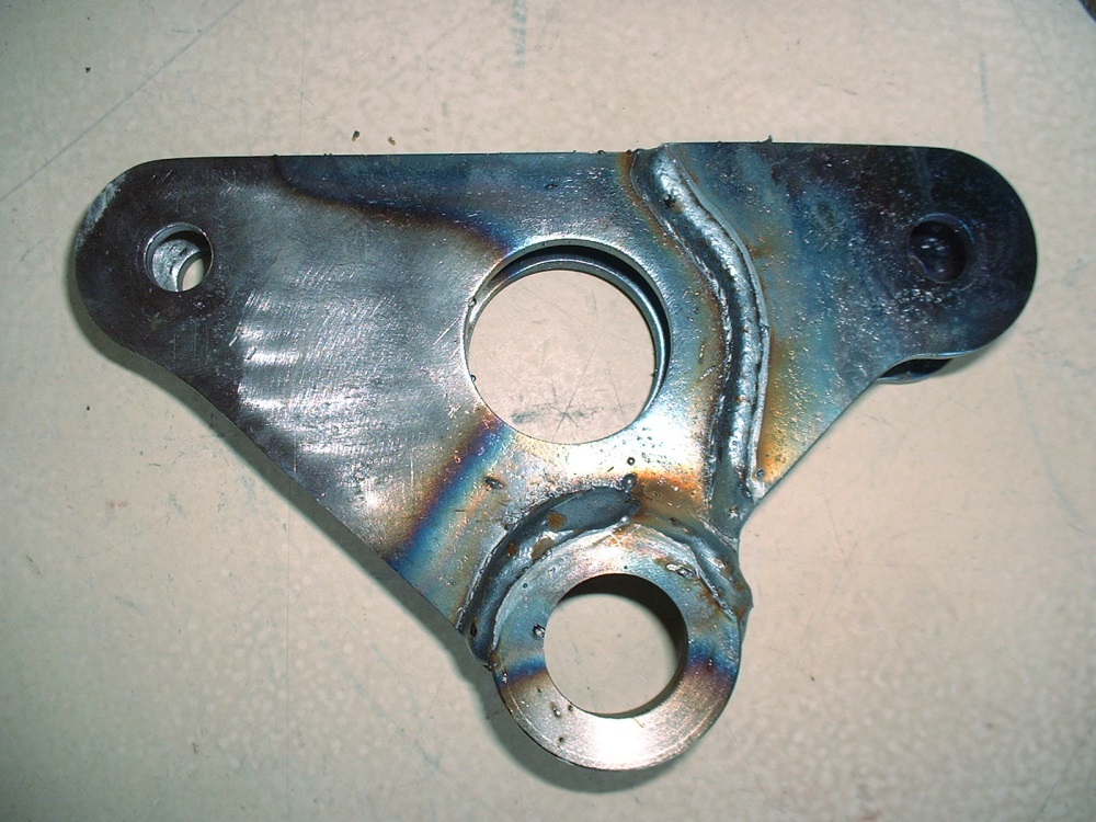
Second order of business is to finish posting the photos of the bell crank build up. Here's a close up of one of them showing just how hot things got to assure good weld penetration between the 3/16" plate steel and the hub which measures 9/32" thick. I find the heat patterns left on the steel are a good clue that there was even penetration. The other thing you can imagine is how disappointed I was with all the spatter, especially after making all the parts so clean and tidy!
After chiselling off the little blobs of molten steel everywhere, attacking the cranks with a sanding disk on my angle grinder, and finally giving them a quick wire-wheeling I managed to regain some of the aesthetics lost to the welding process. At this point I decided to locate where the grease grooves on the bearings would line up with the hubs so that I could drill and tap the hubs for zerk fittings. It would have been a simple process except that I naively believed that I could coax a dull and chipped 1/4" x 28 tap into making threads in four little holes. (You can probably see where this is going.) The first two holes were painful with the tap clicking rather than smoothly inching its way down into the holes I had just drilled. I thought to myself "What the heck... two down, two to go". About halfway through the third hole, the clicking sound abruptly ended in a "SNAP". Followed by a strange sound that sounded like "Mother-@$^*&$% SH_T!". The tap broke off even with the outside diameter of the hub, but was sticking in about 3/16" on the inside bore where the bearings need to go. It wasn't looking good and I had visions of having to remake an entire bell crank. With unbelievable luck, I was able to break up the remnants of the tap using a hammer and pin punch and got it out. I was even able to salvage the threaded hole with a (brand) new tap and make the zerk fit nice and tight. Whew!
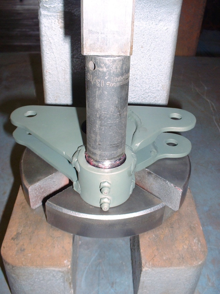
With that out of the way, the next step was to give the bell cranks a quick coat of self-etching primer and press the bearings into the hubs. I had to use an arbour press to get the bearings in the bores despite them being only finger tight earlier. I suspect the hubs deformed slightly due to the asymmetric weld, but it worked out in my favour. I didn't end up using any Locktite 680 to bond them to the hubs.
The last step was simply installing the snap rings to positively retain the bearings in the hubs:
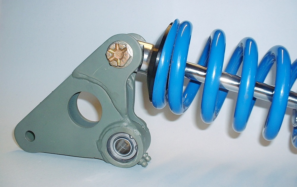
I installed the bell cranks to the QA1 coil-overs just to take a few pics and to get an idea how this was going to look. I think it was worth the effort so far.
Thanks X-Body. I mentioned it earlier, but the reason each side of the main body of the bell crank was made in two pieces is so that I could accommodate the 5/8" width of the pushrod spherical bearing at one end, and the 1" wide spherical bearing at the end of the shock absorber. I could have made the bell crank 1" wide over it's entire length and used spacers on the pushrod bearings to make up the difference, but that would have forced me to use a wider hub since the triangular plates would have been moved further outboard and I would have otherwise lost the shoulder that I used to weld the plates onto the hub. So what's the big deal about using a wider hub? Not much, but I felt the bell crank was going to look quite large as it was and I wanted to minimize it's visual impact. A wider hub would have also forced me to change my bell crank mount design slightly to accommodate it.
Bearings and zerk fittings look great. Reminds me of the time we put an additional 36 fittings in a TD8 dozer. Not sure why they didn't put them in to begin with, (other than cost), but when finished, all moving joints could be individually greased. But that's another story.
You know, I think you could fit one more hole in there for weight savings without compromising integrity or strength..... (J/K...looks great!)
Anxiously waiting to see it in place, doing it's job.
Gotta say it... Sage and Bob, you guys are two of the most loyal posters in my thread and I really appreciate the feedback. So an extra special thanks (and a ratings bump) to both of you.
Back at the bottom of page 21, I started covering the fabrication of the lower bell crank mounts but stopped when I realized I couldn't complete them until I had first sorted out the trailing link mounts, the upper frame rail modifications, and the bell crank itself. Well, those are now complete so I turned my attention back to the mounts over the last couple days. I started by finishing up the LH lower mount. I drilled the 5/8" hole for the bell crank pivot bolt, and then I drilled a large hole to be able to access the head of the pivot bolt with a socket wrench:
Then, I carefully aligned the lower mount on the frame rail stiffener and tack welded it into place. I make it sound like it was a quick and dirty task, but it probably took me an hour or more to make sure it was perfectly aligned.
The next step was to temporarily attach the bell crank and get some fine tuned measurements for the shape and location of the upper bell crank mount. So I first attached the crank to the top of the pushrod:
Then threaded the bell crank pivot bolt up through the hole in the lower mount and added one of the special spacers I bought just for this purpose:
Then slipped the bell crank onto the pivot bolt and added the second spacer:
And was finally ready to spend several days (and more than one painstaking attempt) at measuring, making, and fitting an upper mount... which I'll cover in my next post.
You might want to put a drain hole in that vertical mount though. With the access hole on the other side, water could enter the tube and rest on top of the lower frame rail.
Gotta say it... Sage and Bob, you guys are two of the most loyal posters in my thread and I really appreciate the feedback. So an extra special thanks (and a ratings bump) to both of you.
Thanx for the call-out. It's a true pleasure watching a craftsman create something and you taking the time to document it is just fantastic. Thank you.
Yay! PIP is up and running again! First order of business is to thank Sage and Don for their kind comments... I get energized by the feedback.
Second order of business is to finish posting the photos of the bell crank build up. Here's a close up of one of them showing just how hot things got to assure good weld penetration between the 3/16" plate steel and the hub which measures 9/32" thick. I find the heat patterns left on the steel are a good clue that there was even penetration. The other thing you can imagine is how disappointed I was with all the spatter, especially after making all the parts so clean and tidy!
After chiselling off the little blobs of molten steel everywhere, attacking the cranks with a sanding disk on my angle grinder, and finally giving them a quick wire-wheeling I managed to regain some of the aesthetics lost to the welding process. At this point I decided to locate where the grease grooves on the bearings would line up with the hubs so that I could drill and tap the hubs for zerk fittings. It would have been a simple process except that I naively believed that I could coax a dull and chipped 1/4" x 28 tap into making threads in four little holes. (You can probably see where this is going.) The first two holes were painful with the tap clicking rather than smoothly inching its way down into the holes I had just drilled. I thought to myself "What the heck... two down, two to go". About halfway through the third hole, the clicking sound abruptly ended in a "SNAP". Followed by a strange sound that sounded like "Mother-@$^*&$% SH_T!". The tap broke off even with the outside diameter of the hub, but was sticking in about 3/16" on the inside bore where the bearings need to go. It wasn't looking good and I had visions of having to remake an entire bell crank. With unbelievable luck, I was able to break up the remnants of the tap using a hammer and pin punch and got it out. I was even able to salvage the threaded hole with a (brand) new tap and make the zerk fit nice and tight. Whew!
With that out of the way, the next step was to give the bell cranks a quick coat of self-etching primer and press the bearings into the hubs. I had to use an arbour press to get the bearings in the bores despite them being only finger tight earlier. I suspect the hubs deformed slightly due to the asymmetric weld, but it worked out in my favour. I didn't end up using any Locktite 680 to bond them to the hubs.
The last step was simply installing the snap rings to positively retain the bearings in the hubs:
I installed the bell cranks to the QA1 coil-overs just to take a few pics and to get an idea how this was going to look. I think it was worth the effort so far.
booze I hat to tell you this but the weld holding the bearing holder is going to fail as you did not knife edge the joint between the cam plate and bearing holder this is a big mistake as all the force is going to be on the weld and looking at the joint there is very little penetration of the weld and all the force will be on the weld only
this should have been knife edged then tig welded for max strength as it is the most important weld in the constrution of the cam
Thanks Fieroguru for the suggestion to put drain holes in the lower bell crank mounts... I probably wouldn't have thought of that.
Thanks too Bubbajoe for your opinion on the bell crank welds, but I don't share your concerns. The forces that will be exerted on the welds will be in the same direction as weld beads themselves, not in bending, across their cross section as you seem to suggest. I have assured myself that a fillet weld is perfectly fine in this application, that the weld penetration was excellent, and that the licensed, certified welder who did the work knew what he was doing when he MIG welded them. (BTW, I'm not sure if you're aware that you don't need to quote an entire post with all the pictures like you did above... once you select the "QUOTE" button in someone else's post, you should delete all the photos and text that were inserted in your post that aren't necessary to get your point across.)
I installed the bell cranks to the QA1 coil-overs just to take a few pics and to get an idea how this was going to look. I think it was worth the effort so far.
Umm... Well it looks like you only welded them on one side of the plate. When placed under tension that will result in a "peel" force on the weld, with a greater stress intensity factor than would result in a tension only load case.
Also, you didn't weld the ends of the plates to the spherical bearing shell in the top photo above, which can also serve to increase the stress intensity factor.
Stress intensity factor is a geometric factor that adjusts stress calculations and is very useful in calculating fatigue failure modes.
Is there a reason beyond access that you didn't weld both sides of the plates?
Thanks for pointing out the tips of the bell crank that didn't quite get the weld wrapped around the edges Will. I'll address that with a touch up. The inside surfaces of the cranks weren't welded because of inaccessibility (as you guessed), though I suppose the beads could have been wrapped around as far as possible. (I can take constructive criticism, I just get a little sensitive when the only comment (from the previous poster) other than "it's gong to fail" is "do yourself a favor and ditch your design" (back on page 15).)
Anyways, the upper mount proved to be a bit of a challenge for several reasons. The first was that I had to precisely bridge the space between two objects (the upper frame rail reinforcement and the upper bearing spacer on the bell crank) in 3D space. The upper mount had to be made of several pieces and as anyone who has ever welded steel knows, the parts have to fit bang on or else the first weld will skew the pieces and throw your dimensions. So I started by making the rectangular end plate and the body of the main mount slightly oversized in all dimensions:
My plan was to secure the end plate to the bell crank pivot bolt to give me a platform from which I could take better measurements to the upper frame rail (don't pay attention to the ratty nut I used... it was the only non-locking nut I had in that size):
...and in a slow iterative process I fitted and trimmed the main body portion:
What made it challenging was that the upper frame rail reinforcement that I welded in earlier wasn't precisely vertical, nor was it perfectly parallel with the centerline of the car, and the end plate (of course) was at an odd angle to boot. At one point I ignored the old adage "measure twice, cut once" so I ended up ditching my first attempt and making a second one. I was more careful the second time around and was able to get the part to fit really well:
At that point, with the main body portion of the mount tightly clamped to the upper frame rail, I tack welded the end plate to the upper mount body:
...and checked to make sure the bell crank still swivelled easily and had plenty of clearance:
But I wasn't done yet because I still needed to install the wheel to make sure the tire wouldn't rub on the new upper mount throughout its travel in jounce... remember I said there were "several" challenges to making the upper mount?
I was wondering what you are doing for a front and rear suspension?
Thanx,
Ear-ick
------------------ Me, I sell engines, the cars are for free, I need something to crate the engines in.... Enzo Ferrari....
Aerodynamics are for people who can't build engines.... Enzo Ferrari...
Today they are called garage's, yesterday, they were stable's! Eric Jacobsen.... An advancement, of other voices I came across.
Do not walk infront of me, I may not follow. Do not walk behind me, I may not lead. Walk beside me and be my friend forever. -unknown- found here: http://crystal-cure.com/love-quote.html
Originally posted by pavo_roddy: I was wondering what you are doing for a front and rear suspension?
I'm not sure I understand your question. The last 12 pages have been devoted to the evolution of what I'm doing for the front and rear suspensions. Is there a more specific question you have?
(BTW, PIP has temporarily stopped working again and none of the photos are showing up anymore)
[This message has been edited by Bloozberry (edited 01-21-2014).]
blooze im not saying your what your doing is bad but being trained by a master welder I was always told that lap welds without tapering the material is not as strong and when welding suspension parts to always tig weld the parts as it is far superior form of welding your desine is ingenious just want you to be safe
Yes, I didn't read the whole thread, a lil too big right now. I am wondering if you are you doing yur own custom suspension? Are you using this one, with a 3 inch longer a arm, http://arrautmotorsports.com/ They are the former held suspension components. What I really want to know is, the held suspension has longer a arms to get to the 355 stance, if you are using a custom touch is the suspension arm longer than the Fiero?
12 pages, will have to go through those later, thanx.
Air-eek
------------------ Me, I sell engines, the cars are for free, I need something to crate the engines in.... Enzo Ferrari....
Aerodynamics are for people who can't build engines.... Enzo Ferrari...
Today they are called garage's, yesterday, they were stable's! Eric Jacobsen.... An advancement, of other voices I came across.
Do not walk infront of me, I may not follow. Do not walk behind me, I may not lead. Walk beside me and be my friend forever. -unknown- found here: http://crystal-cure.com/love-quote.html
Originally posted by pavo_roddy: What I really want to know is, the held suspension has longer a arms to get to the 355 stance, if you are using a custom touch is the suspension arm longer than the Fiero?
I bought the complete Held (Arraut Motorsports) 6" track increased suspension (3" per side) plus 1.5" front drop spindles from them. Before I installed anything I decided to study whether there were any performance improvements to be gained from them and found quite the opposite. The front was salvageable by shortening the upper control arms 35 mm and moving the corresponding mounts on the cross member further outboard by an equal amount.
The rear was a different story. Once I theoretically dropped the rear by 2" with coil-overs I found that the rear suspension performance took a steep nose-dive. After several attempts to improve the geometry of the MacPherson strut modified with the Held components, I ended up tossing all of the rear suspension out except the trailing links, and designing a 5 link pushrod system instead. The current status of the thread is that I'm now building up the parts for this new design.
I don't begrudge Held for selling parts that people may or may not notice a degradation in handling, but I have provincial inspectors who must be satisfied that any modification isn't detrimental to performance, so that's why I've taken the route I've chosen.
[This message has been edited by Bloozberry (edited 01-22-2014).]
So as I was saying a few posts ago, there were several challenges to making the upper bell crank mount. The first was to get the correct gap and angles between the upper and lower bell crank mounting plates. This drawing shows the other two key clearance areas that the upper mount had to conform to:
One of the red arrows points out the concern that the tire sidewall might rub up against the outside face of the upper mount at full jounce, and the other arrow shows that the coil-over spring might contact the inner face of the mount in full rebound. So once I had found the sweet spot for the correct angles and gap between the plates, I had to cycle the suspension to see how much more I needed to thin out the upper mount to avoid any interference issues. With the brake rotor and wheel reinstalled, I tried to pump up the suspension into full jounce with a floor jack under the tire but was stopped by the tire sidewall rubbing hard against the upper mount. So I sliced a section out of the upper mount, re-welded it together, and made it clear the sidewall with about 5 mms. Hopefully that will be enough... here's the best shot I could get to show the new clearance:
When it came to checking the clearance between the upper mount and the spring in rebound, luckily there was about 10 mm's between the two... lots of space. The last modification I had to do to the upper mount was drill an access hole for a socket wrench to be able to tighten the bell crank pivot bolt. Here's what the final configuration looks like from the street side looking inboard:
And from the engine bay looking outboard:
Finally, here's what you see when the wheel and tire are reinstalled and the suspension is set at ride height:
Next up: modifying the firewall to accept a new transverse beam that will serve as the foundation for the stationary end of the coil-overs.
Thanks Bob. Stealing a page from Yarmouth Fiero's Book of Convertible Design, I'm removing the lower half of the two Z sections that form the base of the rear window support, and replacing it with a much stiffer beam. In the drawings I posted earlier, this new cross car beam will serve as a solid mount for the stationary end of the coil-overs, the two engine torque struts, the deck lid hinges, and the new MR2 rear glass.
I wasn't looking forward to removing the lower half of the OEM channel because Yarmouth Fiero said it was a real pain in the butt. So I got myself mentally prepared for hours of sitting in the engine bay and drilling out spot welds, but in the end I found it went really quickly, probably because I had already removed the hinge boxes:
Once the spot welds were turned into a little pile of metal shavings on my floor, I tried to remove the Z section by pulling down on it but was prevented by a pair of little supporting flanges that are part of the upper frame rail. I made quick work of those by lopping them off with the die grinder (the red oxide primer is from the previous owner when he stretched the frame):
The Z section needed a little coaxing to remove because I couldn't get to two of the spot welds very well that were tucked up next to the frame rail, but it wasn't going to win the battle. I was actually surprised to see surface rust inside the channel... nothing serious, but it does make me wonder how it got there. It doesn't look like the inside surface of the channel was primed or painted at the factory.
After a few tugs it bent at the big hole I made when I removed the left hinge box, and then it just fell out:
Sitting on the shop floor with the remnants of the spot welds... (my pile of removed OEM sheet metal is getting bigger... I should take a picture of it when I'm done.)
Finally, here's what the firewall looks like without the lower half of the OEM cross-car beam. I'll need to sand off the rust and re-prime the area before the next step, which is cutting and fitting the new beam:
(Edit: forgot to add the last photo!)
[This message has been edited by Bloozberry (edited 01-28-2014).]
Great job removing the metal Blooz. You did a much neater job of it than I did. I found the hinge boxes to be the biggest pain to remove because the welds were so random. I'm sure the spot welding robot went nuts the day they built my car.
Looking forward to seeing your transverse frame in place. I'm hoping it will similar to mine in cross section so we can develop rear deck hinges that fit both cars.
Not that we are counting..... but my scrap Fiero metal pile weights about 70 lbs so far.
To make the new firewall cross member, I re-read Yarmouth Fiero's thread to be sure our cars would be the same in this area since we'll be sharing the same body molds for our cars despite his being a convertible and mine being a berlinetta. I used his idea to take a 3" x 4" x 1/8 wall rectangular tube as the basis for the cross member. The firewall is sloped at about 18 degrees from vertical though, so the tubing has to be modified to fit the firewall snuggly yet have the rear edge vertical. To sort through how I would do this as well as where I would need some flanges on the cross member to weld it to the chassis, I made a cardboard template:
And since Yarmouth Fiero didn't explain why he had drilled several large holes in his firewall, the template helped me figure it out. It seems there are five "bumps" along the top of the sheet metal that protrude into the engine bay and would prevent the cross member from sitting flush against the firewall. This view is from inside the cabin so you'll have to use your imagination what the bumps look like from inside the engine bay:
I found that a 2" hole saw made a nice clean incision, and left a great way to rosette weld the hidden front side of the new cross member to the firewall:
With that out of the way, I bought the materials I'd need: 60" of the rectangular tubing (not a particularly popular size at your local metal supplies shop!) and the same length of some 3" x 1/8" flat bar.
To make the right angled trapezoidal shape of the cross member, I lopped off all of one of the 3" walls of the tubing, and a portion of the adjacent 4" wall. And, in a rare picture of me (not unlike Wilson in Home Improvement), here I am behind my fence making sparks fly with a cut off wheel in an angle grinder:
I think I went through an entire cut-off wheel to zip through a total of 10 linear feet of steel. My wife, who is building some cabinets in the other half of the shop, wasn't too happy with the smell of burning steel. Women. Here's the sectioned tube:
Seems like an awful waste to cut all this material off only to replace it, but then there would be absolutely no way just to cut say, an inch out of one wall and bend it along the entire length of the tube to close it up at the correct angle. I'm sure I'll find a use for the lopped off steel at some point in the project.
Originally posted by Bloozberry: Seems like an awful waste to cut all this material off only to replace it, but then there would be absolutely no way just to cut say, an inch out of one wall and bend it along the entire length of the tube to close it up at the correct angle.
Slot the face of the tube on a mill That should be precise enough that it would bend closed at the correct angle.
And since Yarmouth Fiero didn't explain why he had drilled several large holes in his firewall, the template helped me figure it out. .
Oops..... sorry about that Blooz.
Edit to add: On page 6 of my thread you'll notice my transverse beam suddenly developed a mysterious seam in the middle. As hard as I tried to prevent it, my beam bowed when I welded the 3" x 1/8" flat bar back on. Just an FYI so you don't think I've been keeping any more secrets.
[This message has been edited by Yarmouth Fiero (edited 02-04-2014).]
Thanks Fierogt28, Will, Yarmouth Fiero, and 355Fiero for all your comments. I too am looking forward to seeing the chassis sitting on all four wheels. It won't be too much longer now.
Continuing on with the firewall cross member, the next step was to bend some flanges at either end. I find bending flanges is always a bit of a trial and error process since knowing where to start the bend depends on how accurate your bending machine is. In my case, I don't have a bending machine so getting a precise distance between the flanges at opposite ends of the cross member also took some luck. The dies I have for my hydraulic press couldn't be used because there are just too many flanges to get in the way. So I did it the "shade-tree" mechanic's way. I marked a line where I wanted the flange to be, then moved it another 1/8" further to account for the thickness of the material, and then guessed I'd need about another 1/16" for the bend radius. I then drilled 1/4" holes in the corners of the tube to act as clean stops for the angle grinder and then sliced the tube lengthwise up to the holes:
Then I sandwiched the side of the tube between a couple 1/2" steel plates I had lying around and used a high tech 5 lb mallet to bend the flanges :
Once all three flanges were bent at one end, I double checked how close my flanges were to where I had actually wanted them, then made a few adjustments to locating my bend lines at the other end before doing them. I came within about a millimeter from the overall distance I needed between the two ends of the tube but easily tweaked it a bit until it fit tightly. I wanted to prime the inside of the tube so that was easiest while the fourth side was not yet welded on.
I then tacked the 3" x 1/8" steel bar to the tube in many places to keep it from deforming while final welding it, then hit it up with a full zap:
By this time I had already trial-fitted the new firewall cross member a dozen times so I was getting good at knowing just how to wiggle and jiggle it into place, and just where to hit it with the rubber mallet to seat it. Here's the final mock up before tack welding it:
And a close up of how the flanges tie into the upper frame rail:
Next up is cutting and fitting two vertical supports for the new cross member. They'll rise up from the lower frame rail to the underside of the cross member.


 Once the inside diameter machining was completed, I shaved off the extra 1/4" I had left on the length, centering the bearings between both ends. Here are the pieces that go into making one bearing hub together with one that's assembled:
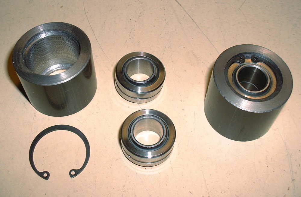


 It's always nice to get some feedback.
 With unbelievable luck, I was able to break up the remnants of the tap using a hammer and pin punch and got it out. I was even able to salvage the threaded hole with a (brand) new tap and make the zerk fit nice and tight. Whew!
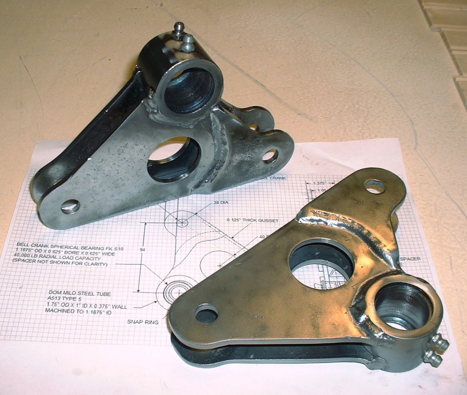


 Here's the sectioned tube:


