These are closest to what I was looking for... I'd like the OD of the bushing shell at the two locations where it presses into the control arm. The first pic above appears to be the OD of the lip of the control arm where the bushing installs. The second pic is the ID of the bushing sleeve at the opposite end.
The OD of the shell at the flange end and the other end are different. This is done so that you don't have to push the press-fit along the entire length of the bushing when installing. It also means that the measurements I need for the detail design pretty much have to come from a naked bushing.
Taking a swag and going halfway between these two measurements is 1.665".
From http://secure.chassisshop.com/partdetail/C73-442/ The weld cup for a 5/8" spherical bearing has an OD of 1.6875... so it could probably be turned down to just the right size to install in the control arms. However, it's only 0.971 long, so it would need an additional shell to support its entire length. The 5/8" rod end is a better choice than the 1/2" rod end. Using the stock 12mm bolt, the 5/8" rod end allows the end spacers to have locating shoulders. The 1/2" rod end doesn't have enough radial clearance around the 12mm bolt for that.
So to use the 5/8" rod end, I'll need to make my own weld cups specifically for the Fiero control arms. <sigh>
How do the '84-'87 and '88 front lower control arm bushings compare? I know that one urethane kit covers both applications.
RockAuto does not show any front lower bushings for the '88, so I can't compare listings via that site. I see that the Fiero Store shows the same bushings between '84-'87 front lowers and '88 front lowers. I'm @$$uming that RockAuto doesn't list them for all years because the '88's may have had a different durometer spec and therefore a different part number in GM's system.
If the shell dimensions are close enough that the same weld sleeve would work for both applications, then I'll just make an additional set to use on my Formula.
I'll also evaluate to see if one design can satisfy the needs of both rears and front lowers for the '84-'87 cars. It would be sweet if one design could replace all three bushing applications.
I ordered a set of '84-'87 rear and front lower bushings from Rock Auto, so I'll have the raw data soon enough.
[This message has been edited by Will (edited 03-17-2013).]
Spent a bit more time with the bushings and scratching out some sketches. I have a configuration of weld cup that I think will work in place of both bushing shells. However to finalize the OD profile, properly locate the spherical bearing axially within the cup and spec the three different end spacer lengths I'll need in order bolt in to the stock chassis pick up locations, I'll need to get my hands on some control arms.
I'm away for Navy duty this month, but will be back the weekend of the 6th.
With the Caddy computer "exploded" to life when started... It would flash to 2000 RPM and settle back to idle. Quite dramatic, but unnecessary. With the Shelby computer, it starts at idle like a normal car. The engine is also much quicker to return to idle when I release the throttle. For the first time EVER, it DOES NOT STALL when I sink the clutch on overrun. The idle is stable, although it "hiccups" when it transitions from cold idle to closed-loop idle. There is no DFCO .
The tune is WAY off... for this engine. It falls on its face at WOT above 2500ish RPM, so I'm thinking it's pulling timing due to knock. I'll have to fill up on Sunoco and see if that gets any better.
Fortunately, this computer is tunable via HPTuners, so I can have any shop with HPTuners that has experience with with LS1's (don't they all?) hammer out the base tune.
The OBDII throttle cam is very different and much more progressive than the OBDI throttle cam. The engine's much more controllable at parking lot throttle now than it was; as a side effect, my right foot calibration had to enter learning mode, and was a bit clumsy on the test drive last night. My dad had a similar experience with the TPI 400 in his Jaguar. The TPI throttle cam wasn't progressive and the car has 3.31 gears, so it was easy to unintentionally to bark the tires when leaving a stoplight. The more progressive LT1 throttle cam mitigated that tendency.
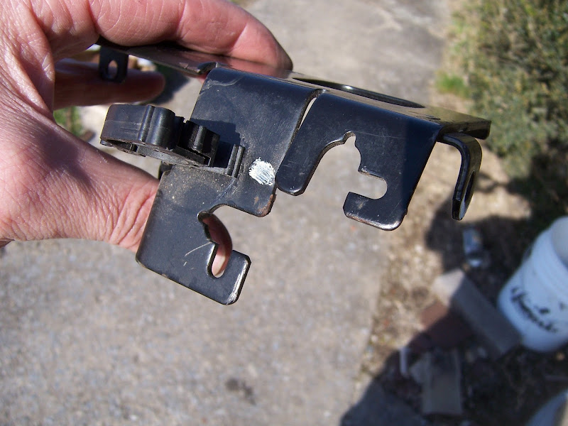
Had to file out an opening for the Fiero throttle cable in the Caddy throttle cable bracket. That was a PITA, but done now.
The hose "nipple" on the MAF housing is slightly larger than the hose connection on the OBDI throttle, so it was pretty tough to stretch my previous intake hose onto that fitting. Now that this throttle with its integral MAF housing is installed, I can work on my 3.5" intake tube, for which I've had aluminum donut halves on the shelf for ever. I will also need to get a couple of different PCV tubes to accommodate the new PCV connection locations.
3.94 gearset, diff side/spider gears, IMS and some extra CV joint cups are back from Liberty's... they're blingin'. Pics of all too follow.
[This message has been edited by Will (edited 04-15-2013).]
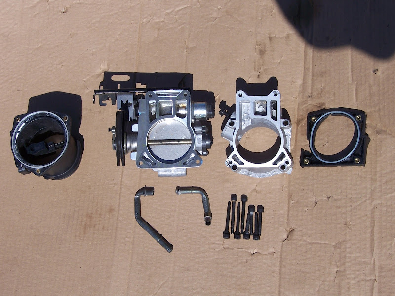
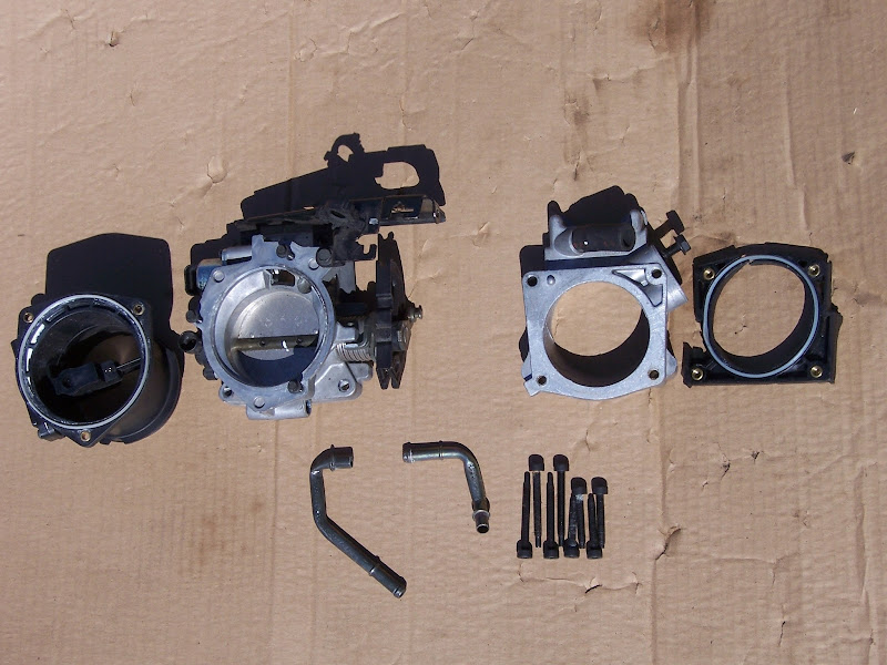
Old assembly vs. new parts. My high tech EGR blockoff plate is visible on the old TB adapter. It had to be modified slightly to work with the new hottness.
Throttle cable bracket... will take a pic of how I modded it sometime.
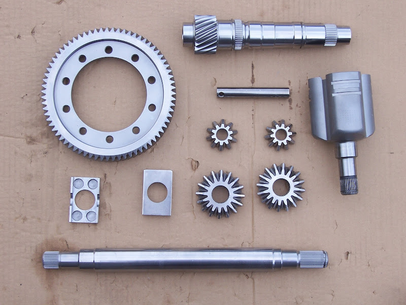
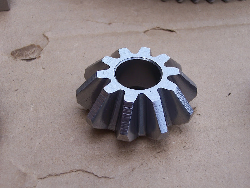
Full set of components that went through Liberty's Cryo+mikronite-like process: Getrag 3.94 R&P; Type II IMS; couple of extra CV joint cups (I think these were cryo only); side gears, spider gears and cross pin from the later style larger Getrag diff; spring plates from an EP LSD for same.
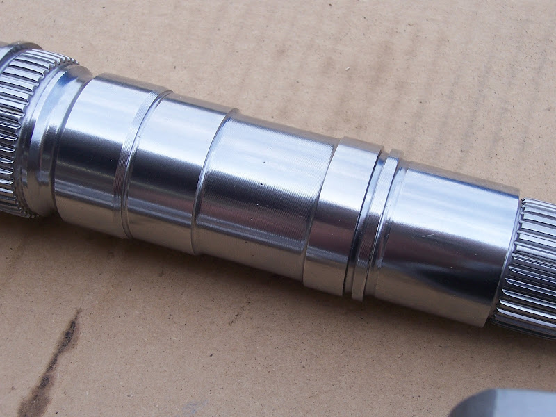
3.94 output shaft... hardness testing marks are *just* barely visible
3.94 output shaft gear teeth and 1-2 synchro splines. Blingin'
One of the spider gears, also with hardness testing marks visible
Transmission end of Type II IMS
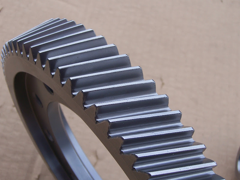
3.94 ring gear. It also has hardness testing marks on the ends of some of the teeth, but those aren't visible in this angle/lighting.
Made some progress on the intake tube: 3.5" aluminum tubing. The bends are from tight radius 3.5" donut halves that I had to order from F@#$ing Australia. The straight sections were rolled by a local sheet metal shop.
It's a graph. It has numbers. It scanned crooked because it was printed crooked.
I'm not sure what was done between the 306 ftlbs run and the 301 ftlbs runs. I hope that will be straighten-outable on my return to the dyno. I'd also like to get him to do some work between 1000 and 2500 RPM, as that's where I do most of my driving, and it's still a bit lumpy in that range.
Also need to be sure the tuner looks at peak injector duty cycle, so I know how much horsepower head room I have before I have to start looking for injectors.
This was Tuesday of last week. The tuner had problems with KR because I had a brain fart and still had the OBDI knock sensor, even though I'd switched to the OBDII PCM. I bought a new sensor and pigtail from CarQuest and installed that sensor late last week.
When I first assembled the engine, I used new valve cover seals. I did not have any problems with leaks. I took the valve covers off to re-torque the head studs and forgot that the seals are one-time-use. I reassembled with the old seals (because I had to move the car) and both covers leaked. I replaced them both again; the rear cover sealed up, but the front one still leaked. Just last weekend, I replaced the front seal AGAIN, and it finally seems to be sealed.
I have ordered a PCM bracket.
I need to measure the available space inside the quarter panel so I know which K&N to order. When I have the filter, I can finish the intake tube. Once that's done, I'll go back to the dyno for a touch up.
I have just a few more things to do to it, and then plan to leave it alone over the summer. I'll try to take it to the Texas Mile in October, followed by a round of engine-out mods. A few more things to do: -Mount PCM -Complete intake tube -Retune -Spherical bearing suspension pivots -Install treated axle components -Complete/install oil pan heat shield -Design/install oil/water heat exchanger
Hoping for ~320 RWHP at this point
Engine-out mods: -Install 3.94 ring & pinion with EP LSD. -Install worked crank with corrected rod journal diameter and rod bearing clearance -Install ported heads -Install Y2K+ intake manifold -Install 266 intake cams in exhaust locations -Rework wiring harness and find permanent home for PCM -Remove stock oil fill, install new oil fill and paint valve covers -Repair/replace right decklid hinge box and chassis side dogbone mount bracket -Chromoly flywheel?
Hoping for 360 WHP and will turn 7500 RPM at this point
Afterward: -Headers -288 reground cams -Throttle per cylinder -Even bigger cams from custom billets? -Franken F40 with '07 first-fifth, 0.62 sixth and 3.91 final
Final goal: 450+ RWHP and 8500 RPM
[This message has been edited by Will (edited 05-10-2013).]
Dang! I still have the random stall using the LS1 unit. I also have the high rpm start and then drop to 750. The HP Tuner didn't get the stall problem tuned out. So, what did your shop do? I have the mild 272 cams too, eh. I've seriously thought about going back to VIN 9 cams.
Why the Y2K intake manifold?
[This message has been edited by IXSLR8 (edited 05-05-2013).]
Originally posted by IXSLR8: Dang! I still have the random stall using the LS1 unit. I also have the high rpm start and then drop to 750. The HP Tuner didn't get the stall problem tuned out. So, what did your shop do? I have the mild 272 cams too, eh. I've seriously thought about going back to VIN 9 cams.
Larger camshafts are less efficient at idle, so they need more airflow and less fuel to avoid stalling/surging. It sounds like you need to increase the Base Running Airflow values. With the right airflow values the engine RPMs will drop to idle RPM w/o stalling.
After some more driving time, I've found that it has the flared start when it's cold, but on hot restarts it barely exceeds idle.
Your cams definitely affect your idle tuning. Not all tuners are created equal. If the tuner is good at getting cammed up LS1's to idle, he should be able to do it for you.
I have 288's on the shelf, so I'll be dealing with the same thing in a while.
Bigger runners than the '93-'99 manifold to go along with the bigger intake ports on the roller cam heads. CHRF's numbers for ported flat tappet heads get to about 280 CFM on the intake; ported roller cam heads top 300.
I'm making an educated guess that the stock Y2K manifold will be pretty close to the right size/shape/location/angle to work with ported flat tappet heads. I'll probably end up doing a mock assembly without valves so that I can judge how close the manifold and ported heads will end up being... may have to spend quality time with a sanding roll to get the interface perfect.
[This message has been edited by Will (edited 05-17-2013).]
Proof the valve cover comes off with the engine in the car:
Blingin' new mad JDMTytej0 blue valve cover seal (plug well o-rings not installed):
This may have been the problem
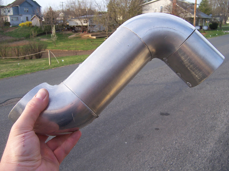
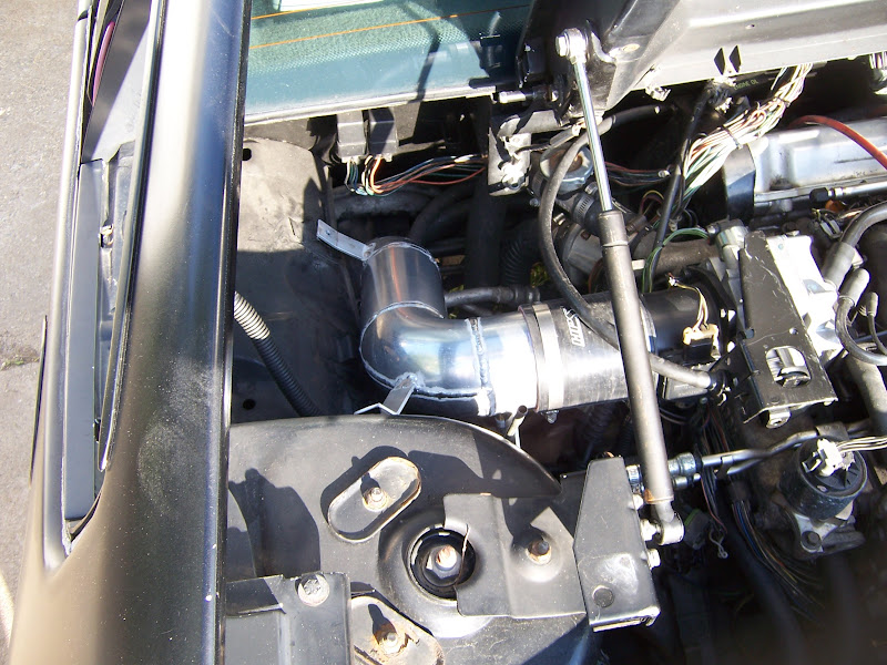
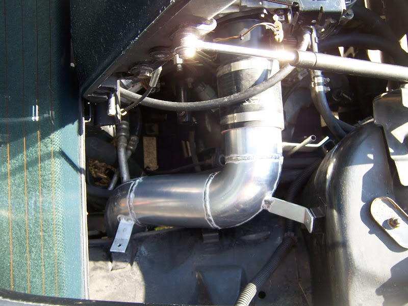
Finally finished the CAI. It's been on the car a couple of weeks now, but the car's been at my dad waiting for some rust repair on the passenger floor pan. The really good welder is moving about 2 hours south of my dad's place (about 3-3.5 hours from where I live) and starting his own shop. Good luck to him, but that means now I have to start paying for welding (and learning how to do it myself). The guy at the fab shop I've had to use has already had some "interesting" interpretations of my directions for both the diff snout bracket on the Eagle project and repair of The Mule's right rear engine mount bracket.
The CAI can be installed without disconnecting shift cables or removing the shift linkage, but it's very tight and needs a little persuasion in order to squeeze between the bottom edge of the stock fenderwell pass-through and the fuel fill pipe. It's 3.5"... I'm not sure how Sinister got a 4" pipe through.
The induction noise is quite different. The old setup of a mitered stainless pipe with parts store paper filter in the engine bay sounded like a combined jam session with Metallica and Skrillex when I put the loud pedal down and ran out the RPM. Now it sounds more like a sporting V8. I was also surprised to find that I could tell a difference in the location of the source of the sound.
Without further ado, I give you the frankenstien caterpillar pornstar;
With BDSM accessories:
The old crappy setup:
The new hawttness:
Top view:
Across the bay angle:
It doesn't show up in any of the photos (I guess that was the idea--to keep it out of sight) but there is a bung for the IAT on the bottom of the tube right next to the coupler to the MAF housing. I re-routed the IAT wires from being bundled with the fuel pump and A/C clutch relays to being bundled with the TPS, IAC and MAF wires.
[This message has been edited by Will (edited 06-05-2013).]
Had some driveability problems that were partially fixed by replacing the coils and probably will be completely fixed by replacing the ignition switch.
Body side ground had deteriorated... new screw and some dielectric grease in it, and it works again.
The engine block grounds from the engine wiring harness had deteriorated a bit, too. I replaced both ground lugs/loops and they're doing ok again. Time for plugs...
Making headway with Torque in that I was able to load the predefined set of GM PID's, BUT I'm getting junk data for the injector pulse widths and misfire counters.
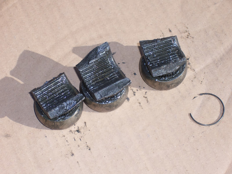
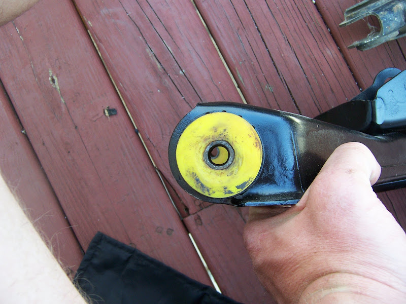
This happened a couple of weeks ago on my way back from the bank:
I eased out from a stoplight until the clutch was hooked up then punched it and had a free rev... I had enough momentum to make it to a parking lot. Came back later and brought it home on a rope. My dad was able to raid the stash and send me another tripod assembly.
The cup I broke at the dragstrip and this tripod were both in the car for the 1.5 years I daily drove it in P'Cola, so this is most likely the result of long term accumulation of overstress.
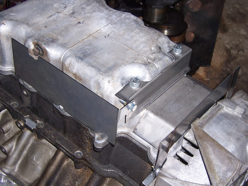
Also, finally got my heat shields done:
I'm not sure if the bolt that holds the two pieces together will clear the exhaust or not. If not, I'll replace it with a great big pop rivet or similar.
There's about 1/16" between the under-pan heat shield and the pan and about 1/16" between the heat shield and the pipe. I was testing it in the car before I decided I needed to make the rear face heat shield that would interface to it.
[This message has been edited by Will (edited 01-18-2014).]
The fiero clutch switch was backwards if I remember right. I had to wire it the way the Shelby liked it.
I do have the mild 272 cams...the Shelby program netted nothing over stock STS cams by my local performance tuner. I'm thinking about reverting back to stock cams to see if that makes any difference with stalling.
Who did your base tune?
[This message has been edited by IXSLR8 (edited 02-02-2014).]
How's the LS1 computer working? I still have that dang stall issue.
More than likely, you need to increase the values in the Base Running Airflow Table and possibly adjust the Throttle Follower and Throttle Cracker tables. My LS4 is running an auto only calibration with a 224/232 camshaft and a 6 speed and don't have any off throttle stalling issues... its all in having the right values in the tune. Larger camshafts need more airflow at idle.
The fiero clutch switch was backwards if I remember right. I had to wire it the way the Shelby liked it.
I do have the mild 272 cams...the Shelby program netted nothing over stock STS cams by my local performance tuner. I'm thinking about reverting back to stock cams to see if that makes any difference with stalling.
Who did your base tune?
Sinister set it up to run with the Northstar, but didn't have access to the right MAF tables. I had a local tuner dial it in.
The beauty of the Shelby computer is that ANY tuning shop (or you if you throw down for HP Tuners) can make changes.
I don't know why you'd have problems and I wouldn't, though. I guess your cams vs. the idle settings might be causing your stalling issue. That should be straightforward to tune out as any tuning shop has seen dozens of cammed LS1's. I told the shop I went to that it would be like tuning a full-bolt-on LS1 that still had the factory tune and he did fine. You did tell him yours is cammed, right?
I have 288's on the shelf, so I'm probably going to go through some of the same problems when I upgrade.
[This message has been edited by Will (edited 02-03-2014).]
If you are going to spend the $$$ on an engine swap, go ahead and buy a tuning package and learn to tune it yourself. It will save you a lot of headaches and likely more $$$ in the long run.
Hey Will. There is supposed to be a company in Canada that does super strong axels for the fieros. I might be able to get the manufacturers name if interested. I belive they were around $1400. Supposed to be good enough for the dragsters up to 1000 horse. Also you referenced a Shelby computer. Like in mustang shelby or is that a brand?
Hey Will did you see Blooze's post on the certs he used. Those look about 4 times stronger than the regular certs. Just thought I would remind you if you hadn't seen his post.
Hey Will. There is supposed to be a company in Canada that does super strong axels for the fieros. I might be able to get the manufacturers name if interested. I belive they were around $1400. Supposed to be good enough for the dragsters up to 1000 horse. Also you referenced a Shelby computer. Like in mustang shelby or is that a brand?
I thought about upgraded axles and even located a few sets of the 94mm output flanges used in the Ecotec racing program. I could build custom axles, spending $1000-1500, only to move the weak link inside the transmission. As it is I can replace a broken axle in about 30 minutes... and it's cheap to throw spares on the shelf. It's much more difficult to replace a Getrag.
The Shelby computer uses the .bin from the Shelby Series 1 supercar in the PCM from an LS1 Camaro.
quote
Originally posted by Diamond Dave:
Hey Will did you see Blooze's post on the certs he used. Those look about 4 times stronger than the regular certs. Just thought I would remind you if you hadn't seen his post.
I'm familiar with them. Thanks. My standard serts are holding fine and I have ARP studs.
[This message has been edited by Will (edited 03-04-2014).]
I know ARP's are from volkswagen right, but what does ARP stand for? Also since you straightened out my thinking on the axels I wanted to let you know that I agree with you 100%. Rather break an axel than a transmission any day. Can you build those heat shields again and what would it cost me for a set? I think that is a very smart move.
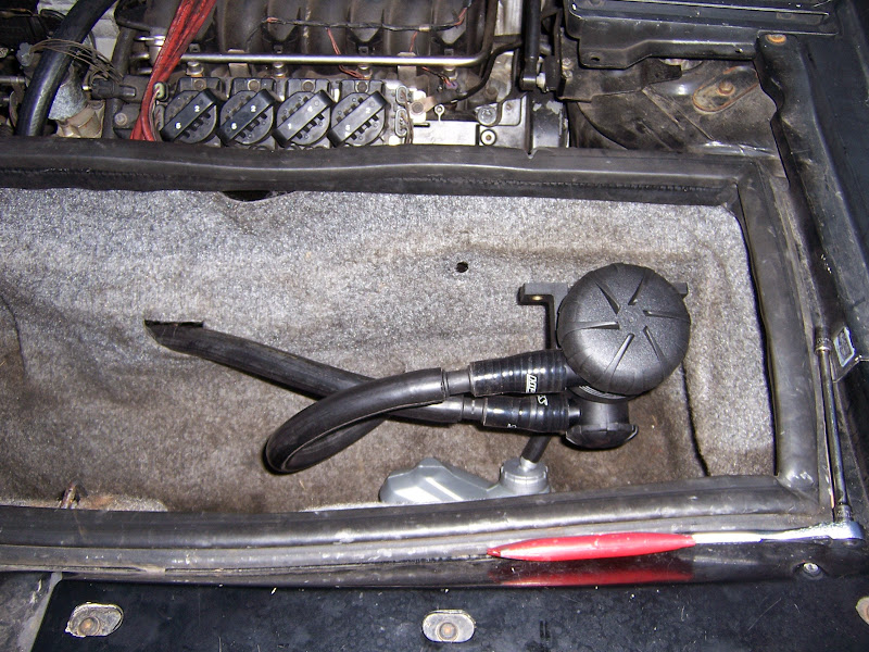
Ultra-ghetto temporary installation, PRE-mounting. I have since attached the separator to the trunk wall reinforcement with a couple of screws.
Crankcase outlet. Now that it's heat cycled a few times, the hose has relaxed and fits better.
Manifold connection. If you look closely you can see that I did grommet the holes. I did not cut holes in my trunk bulkhead for this... I'm just reusing the coil/alternator blower ducting holes... since the coil/alt blower is long gone.
The thing I hate most about '84-'87 front control arms:
The other thing I hate most about '84-'87 front control arms:
The pivot axes are not aligned.
This makes using anything except sperical bearings a recipe for binding in one way or another. I wish I had known the design was that screwed up before I wasted hours on the lathe making UHMW bushings.
However, I *did* get most of the design work for spherical bearing shells done.
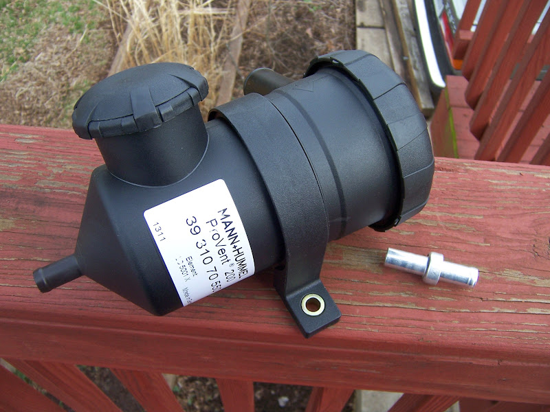
I like the subdued look of that Pro-vent, exactly what I looking for to use on the GN. If you can I'd like to know how well it performs on your car, and where you bought it too.
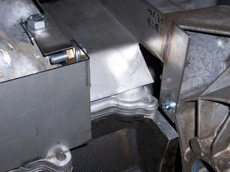
Since the Fiero wasn't designed for a 350 HP engine, things like this happen:
So I had that welded up and a little reinforcement added where I thought the factory welds from the crossmember to the rail were inadequate
Then I started taking apart some old knuckles that I'd had on the shelf for years
I had been thinking that they were C5 knuckles, but they aren't. I'm actually not sure what they are, but they bear significant resemblance to CTS rear knuckles. The CTS was fairly new when I think I bought them on ebay.
The parking brake seems essentially identical to the Corvette mechanism. The parking brake backing plate bolts right onto an aluminum Grand Am knuckle I had lying around. This knuckle will bolt up the 12" W- and F-body brakes and only differs from the W-boy knuckle in the way the strut attaches... it's much closer to bolting up a Fiero strut than the W-body knuckle is. However, as can be seen in the photos above, there are two long bolts through the knuckle which secure the mechanism to the knuckle and react any torque loads from the parking brake. These are not present in the front knuckle, obviously. Adding them would be a fairly serious machining and fab operation and is not practical. The parking brake can probably be made to work without... it would just be more flexible as the loads are only reacted via the (very thin) backing plate.
I thought I had a pair of Corvette hubs to play with, but evidently I do not.
Minor victory: I have my PCV system fully sealed now.
When I installed to the OBDII throttle to go with the Shelby computer, I had to change to the OBDII PCV tubes. The OBDII fresh air tube connects to the throttle so that it draws metered air (been through the MAF) into the PCV system. The OBDI fresh air tube connected to the intake boot. Both tubes go to the same location on the forward cam cover. The formed nylon tube is the same diameter between the OBDI and OBDII styles. However, the OBDII assembly has a larger diameter fitting at the connection to the cam cover. The OBDII grommet designed for this larger fitting requires a larger hole in the cam cover. I didn't know that at the time, so when I tried to put everything together, it didn't fit. Also at the time I didn't realize that I could just pop the fittings out of the formed nylon tubes and swap them, so as to run the OBDI fitting in the OBDII tube. I put it together without a grommet, with just a little bit of a gap around the fitting. I lost track of the OBDI grommet, too, naturally. I later realized that this was a metered air leak. I had to get a new grommet, which between the higher cost of NOS parts and exorbitant shipping ended up costing me $30. I installed the old fitting in the new tube and put everything back together, so now I eliminated a metered air leak that was affecting my idle BLM's.
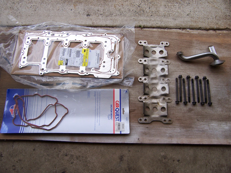
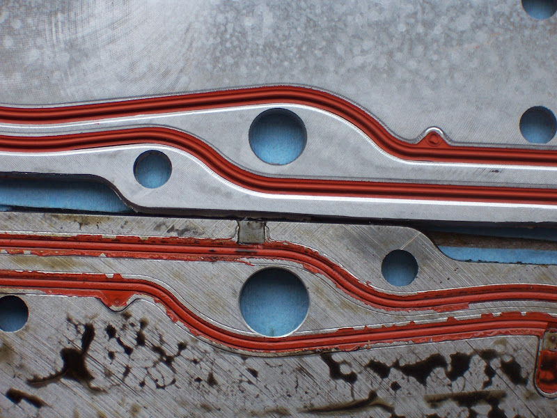
Major work: Just replaced the oil manifold plate and swapped windage tray, main bolts and oil pickup tube to new style design; side effect: ~8 oz of weight savings
I'd been noticing oily deposits accumulating on the outside of the block. After inspection and consideration, I decided that the oil manifold plate on the bottom of the lower crank case was leaking. When I assembled the engine, I modified and then reinstalled a used oil manifold plate, not knowing at the time that pretty much all the gaskets on the engine are one-time-use. I decided that it wouldn't be a big deal to install a stock oil manifold plate, and use the mods I did to the one in the engine as a template for making a better one from scratch.
Without further ado:
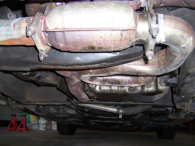
The bottom of the car after a few thousand miles of driving... the exhaust is much dirtier than the last photo I took.
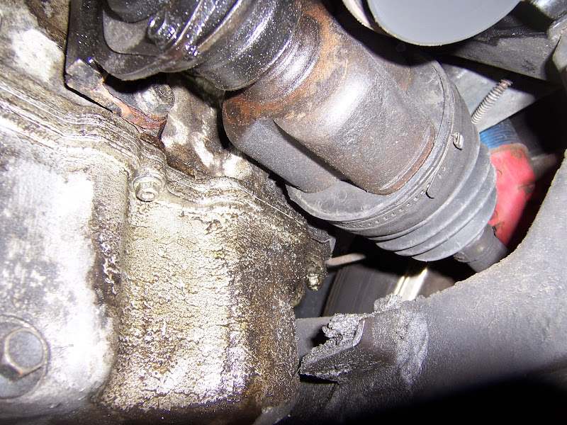
Oil schmutz on intermediate shaft and right inner CV joint:
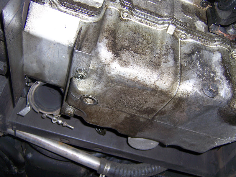
OIl stains with exhaust removed:
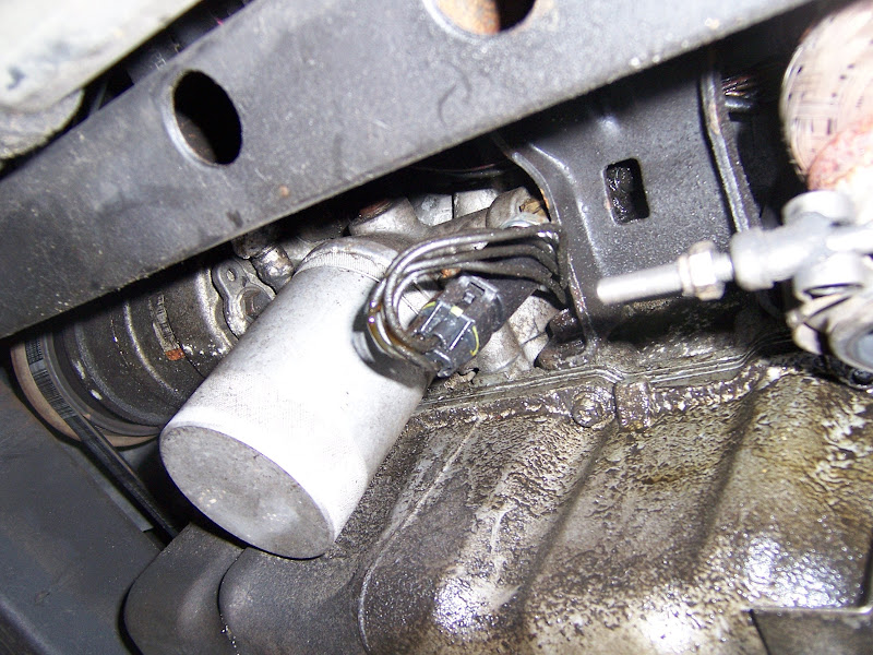
Closer view, can also see the remainder of the stock Fiero engine mount "tray":
The front side of the block:
More schmutz:
Old style setup with oil pan removed and crank pulley blocked up on 2x4's; the front of the engine needs to come up a couple of inches to reach the front oil pan bolts
Windage tray removed:
New parts ready to go in:
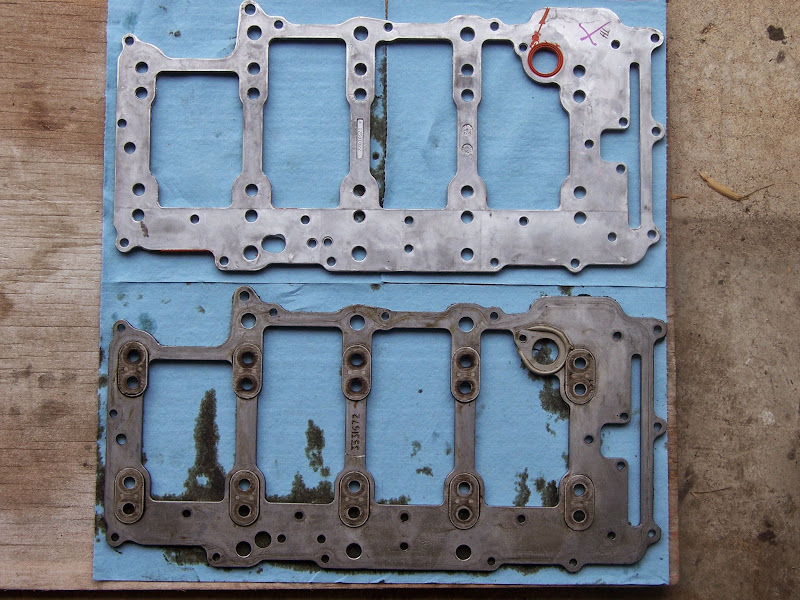
Overall comparison of the manifold plates; the grey "ring" on the old one is oil resistant RTV I used to seal the new style pickup tube to the old style plate which didn't have the built-in seal:
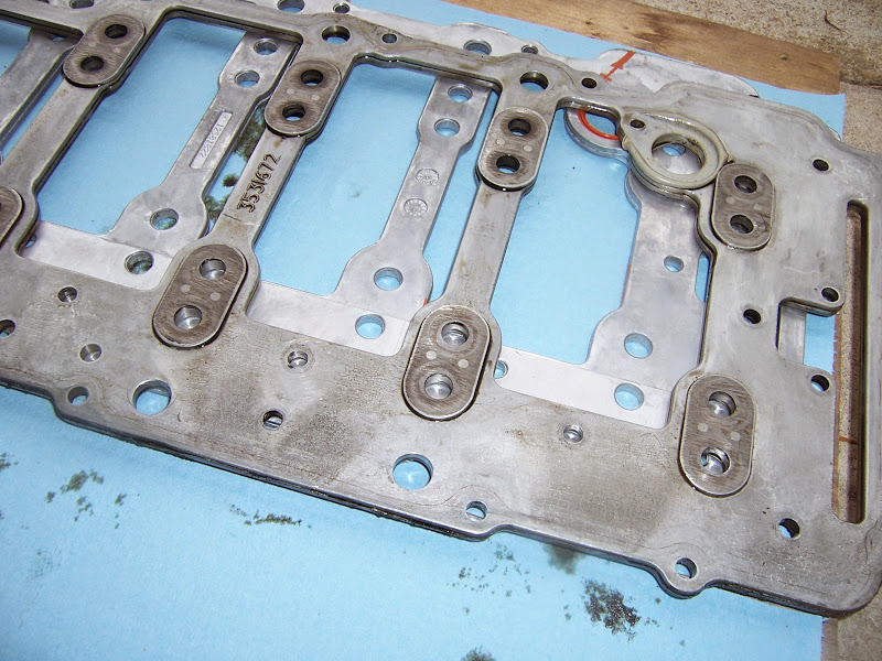
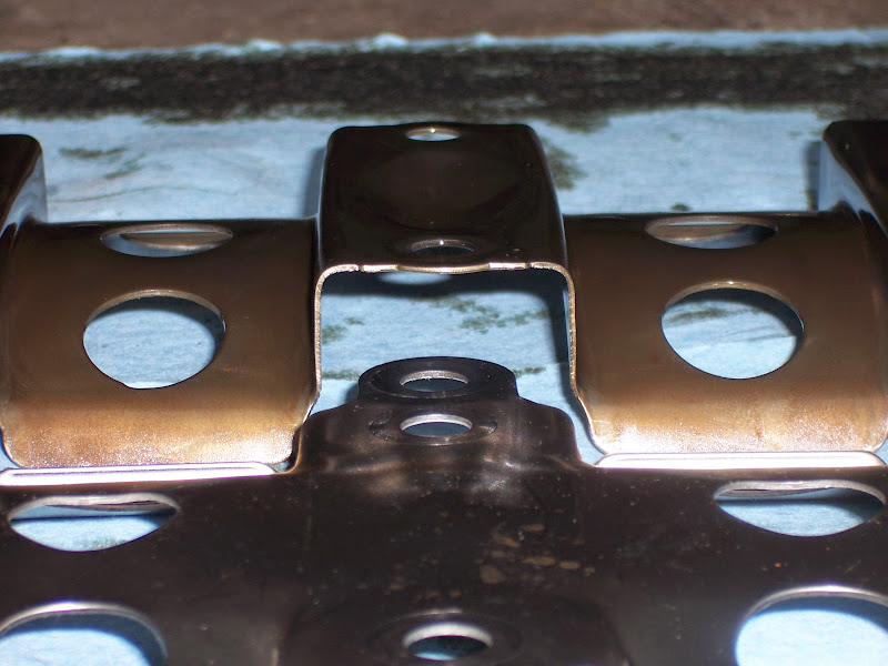
Here's the big difference. The old style had cast-in-place steel bucks against which the main bolts tighten. The new style plate doesn't have those. Instead the main bolts tighten against the steel windage tray
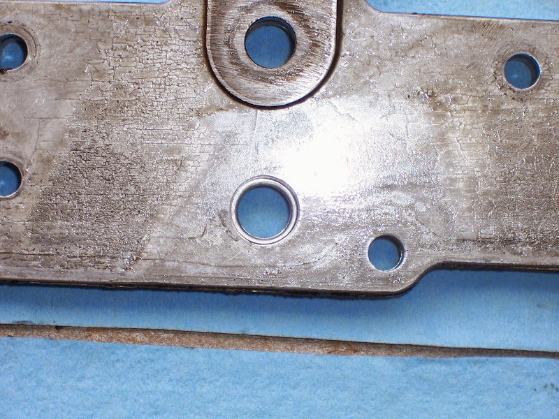
The biggest mod I made to the old one; this is an oil drain back hole. These holes are cored in the lower crank case, so they taper, small end at the bottom. They can be drilled out (one had to be located on a mill, though), but then the holes in the manifold plate need to be opened up also:
Here's why it's ticklish:
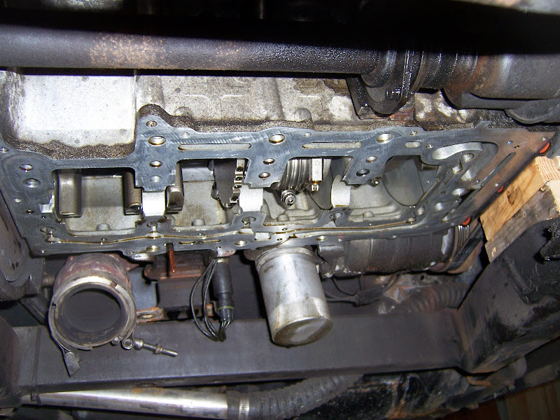
Lower crank case with the manifold plate removed:
Comparison of the detail differences between the windage trays:
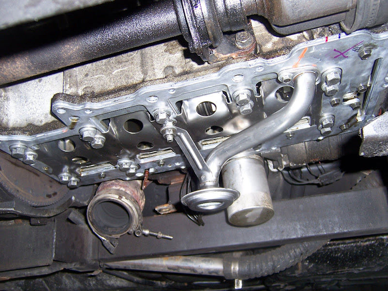
New hardware installed
The parts that came out; I saved the weight of the nuts, the stud heads on the bolts and a few grams out of the windage tray:
Also had a realization about my oil consumption... I need to dig out my invoice from Total Seal and have a discussion with them. If I used low tension oil rings, those in combination with my large bearing clearances could certainly explain my oil consumption. At the time I didn't realize (or maybe just didn't connect the dots) that low tension rings require exquisite crankcase oil control.
Also, looking at options for intake and throttle body upgrades. I *think* that later in the production run, the Northstar and LS engines started to use the same throttles. Does anyone know what a 12555840 does? It looks like an adapter coupling that bolts to the LS 3 bolt throttle connection, but the other side looks like it just takes a round tube...
[This message has been edited by Will (edited 07-25-2014).]
Originally posted by Will: Does anyone know what a 12555840 does? It looks like an adapter coupling that bolts to the LS 3 bolt throttle connection, but the other side looks like it just takes a round tube...
It looks like a rubber hose/gasket that sits between the actual intake manifold, and the coolant pump housing, which the throttle body actually bolts to: