I've always liked the look of polished metal over chrome.
quote
Originally posted by Bloozberry: It’s a messy job requiring safety glasses and a mask because the aluminum dust will end up in every one of your bodily orifices if they’re not covered… (yet another reason not to use a grinding wheel in the buff!)
This by far ranks in the top 5 of my favorite threads of all time. The level of detail you put into the project is inspiring and makes me want to tear my engine apart to detail it. Have you given any thought on how to keep the polished aluminim clean and shiney? I had aluminum wheels that were a bear to keep polished and took a lot of work.
This is the first time that I have read over this thread and you are doing an amazing job. Your car is going to be a work of art when finished if you keep up doing this the way you are going. I will follow this thread. I think I need to get some caddy manuals on my site now as well.;
Thanks Gokart for stealing page 6... so far, I only own page 1 and I'm the one doing all the work!
Thanks for the compliments there too Topcat and Thomas. For Topcat, there's no magic formula to keeping the aluminum nice and shiny that I've found so far. The corrosion forms in the pits, so sanding and polishing takes care of a good deal of the problem. The quality of the aluminum also makes a big difference though. I've polished the intake plenum on my TPI small block only once and over 14 years it's never oxidized. On the other hand, I polished my 2.8L plenum on my '86 and had a tough time keeping it looking good. Last year before storing it for the winter, I repolished it and tried spraying it down with WD40 to get a protective film on it. It worked great but it left me with a different mess to clean up in the spring, though it's far easier to wipe off the WD40 than to try to clean off oxidation. I may try using car polish (carnuba wax) in an attempt to keep the pieces from tarnishing on the N*. The polish should fill in any voids preventing moisture from getting into the tiny surface imperfections. I'm keeping my fingers crossed that the engine block is made of the same alloy as my TPI plenum, but so far it looks like it's not.
Fiero Thomas: I think Caddy service manuals would be a great addition to your site. AJxtcman has already scanned in a lot of the engine inspection procedure in this thread here: www.fiero.nl/forum/Archives...090219-2-082157.html and much of the rebuild manual in this thread here: www.fiero.nl/forum/Archives...100421-2-080614.html Both are archived now so they're not as easily found as when they were active threads. They may save you some time if you're serious about adding Northstar info on your site.
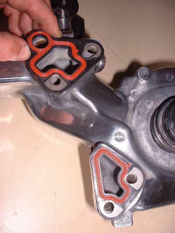
Anyhow, to finish up the water log I still needed to install the EGR valve since I plan (at least at the moment) to run OBD2. I figure emissions testing isn't going to get any slacker in the future so I may as well keep the pollution provisions intact. The first thing is to install a new gasket.
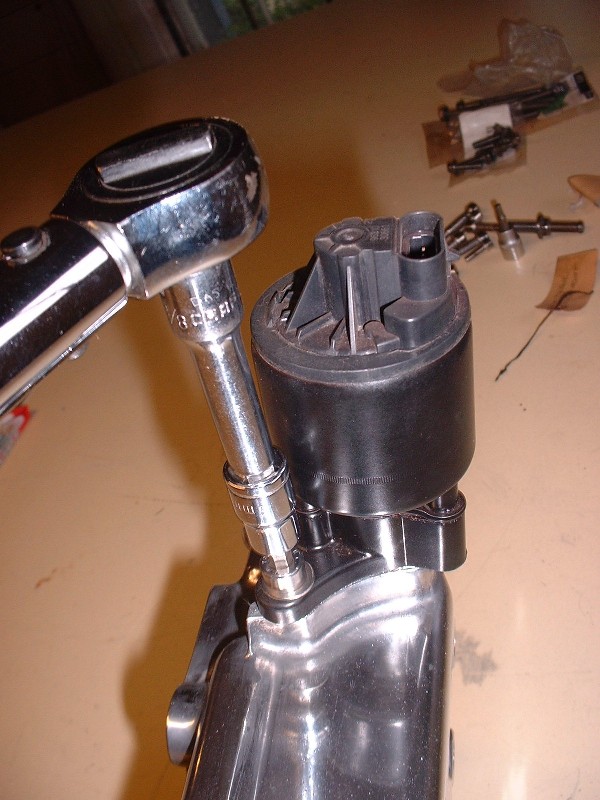
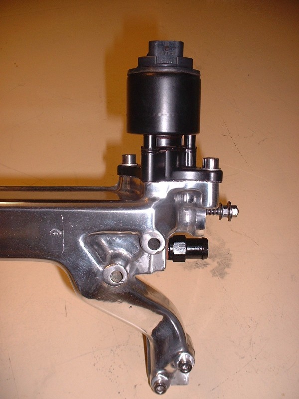
Next, the EGR valve itself. It's strictly an electrically controlled valve as opposed to the electro-pneumatic valve on the Fiero. It's a straight forward two bolter, torqued to 89 lb-in. No vacuum lines to contend with, just a single four pin connector. The water log has an integral channel drilled through completely separate from the water circuit to route the exhaust gases from one side of the engine to the other. Flex lines similar to the Fiero V6's EGR tube connect the exhaust system and the throttle body to the water log.
Here's what the EGR valve installed on the water log looks like:
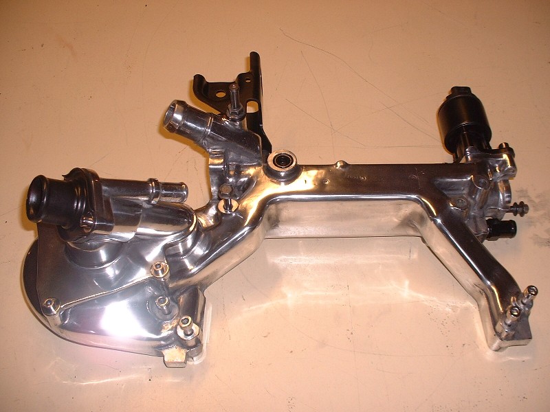
And finally, the completed polished water log with everything on it... well, it's missing the water pump belt tensioner, but I'm still working on polishing that little piece.
LOL. "Hi. My name is Dave and I have obsessive compulsive disorder. It's been 8 hours and ten minutes since someone pointed out an error I made, and even though it's bugging the hell out of me, I've so far refrained from editing my post."
Originally posted by topcat: Have you given any thought on how to keep the polished aluminim clean and shiney? I had aluminum wheels that were a bear to keep polished and took a lot of work.
Someone told me WD-40. Spray it and wipe off the excess.
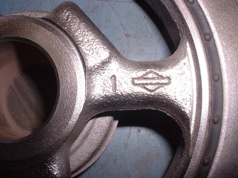
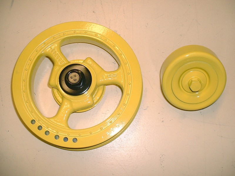
A few odds and sods for this post: I bead blasted the harmonic damper to get it nice and clean for paint when I noticed something interesting:
Anyone recognize the symbol? It sure looks like the Briggs and Stratton logo to me. I wonder why that would be stamped into the damper. Hmmmm… are there any 32 valve lawn mowers out there that I’m not aware of? Anyways, once it was nice and clean I sprayed it with some Tremclad red oxide primer, then a coat of gloss white, and finished with a coat of John Deere yellow. I use the white undercoat to really make the yellow pop out. I plan on painting all of the pulleys and idlers yellow to match the current plan for the exterior of the car. And no… before anyone asks, it’s not going to be John Deere yellow, but it’s not far from it. The John Deere paint is just a great inexpensive way to get a nice bright yellow on the accessories. I find that the Tremclad yellow is very orangy.
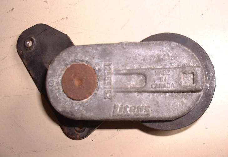
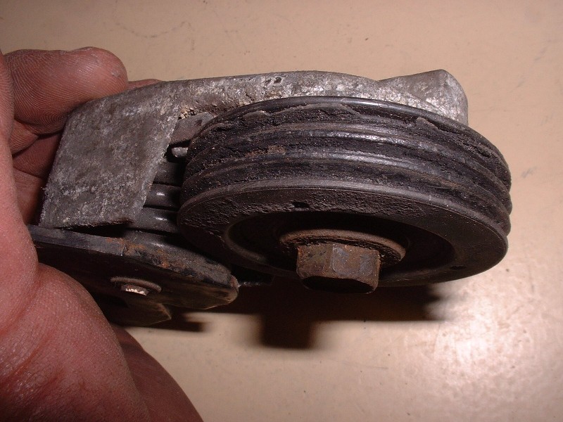
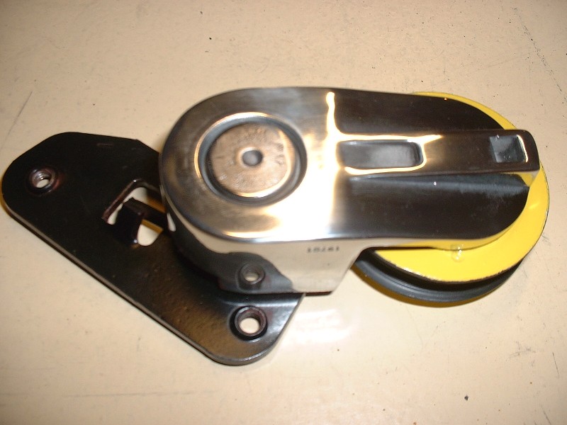
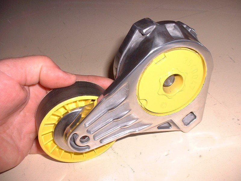
While working on the water pump pulleys I found yet another reason to go over your junkyard engine with a fine tooth comb before just plopping it into your car and hoping for the best. This is the water pump belt tensioner:
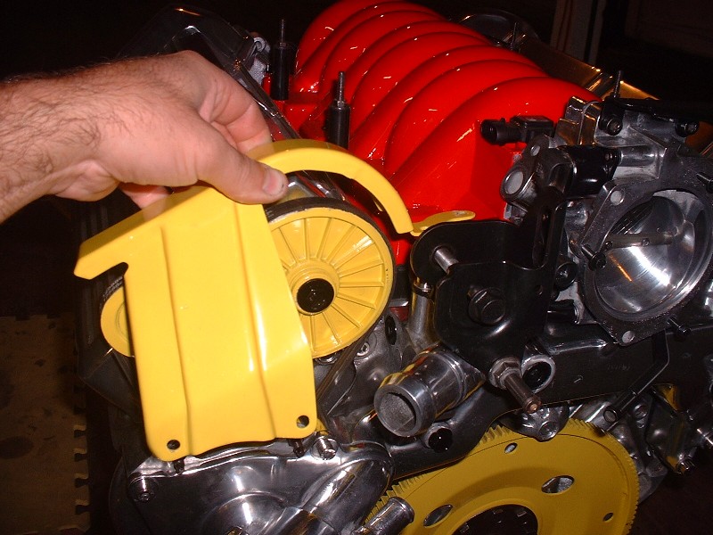
Apart from a little corrosion, it doesn’t look all that bad, except that the tensioning pivot point was seized and the pulley was coming apart. I’m pretty sure in no time it would have ate up the little water pump belt. And since it’s not in an easy place to inspect once it’s installed in the Fiero, it could easily lead to an overheated engine. It’s up against the front wall and is hidden with a small sheet metal belt guard to protect probing fingers:
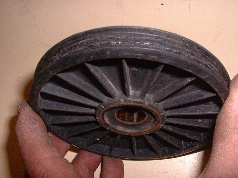
The pulley core and outer ridges are made of steel with a plastic coating. The two middle ridges on the pulley are entirely plastic. No biggie right? Just remove the pulley and order up a new one. Except that GM doesn’t sell the pulley and the tensioner separately… of course not! And the cost… are you holding onto your socks? A whopping $197. Unbelievable. Good thing I have my second engine to rob parts like this off of. If you need one and can afford it, it’s part number 12555153.
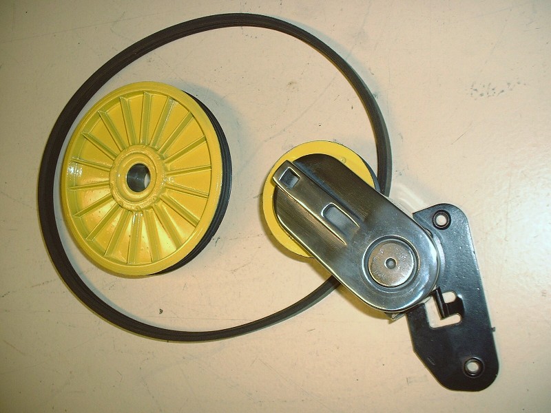
Surely I would have better luck with the cam-mounted pulley right. Strike two! The middle ridges looked like a mouse had munched on them for breakfast, lunch, supper, and a bedtime snack. Aside from that explanation, I have a hard time understanding how this would happen. Again, the dealership wanted five times more money than the part could possibly be worth… $69.25. It’s GM part number 03535846. Spare engine, to the rescue!
After spending a couple hours bead-blasting, sanding, polishing and painting various parts of the water pump tensioner, here’s how it turned out… like a little jewel.
And here’s the cam pulley along with a shot of the mini serpentine belt (GM p/n 12588412 for a mere $19.97)
Thanks for the suggestion Erik… I haven’t had this thing out in the sun yet. It’s bright enough to look at just in the darkness of the cave I call my workshop. (insert smiley face with shades)
So on with the water log/pump installation: The first thing to do is install the cam pulley. It’s fairly straight forward… just slip it on the end of the cam shaft with the snout pointing outward, and use any old 8mm X 1.25 bolt in the end of the shaft to draw it into place. When it’s seated correctly, the end of the shaft is flush with the end of the snout.
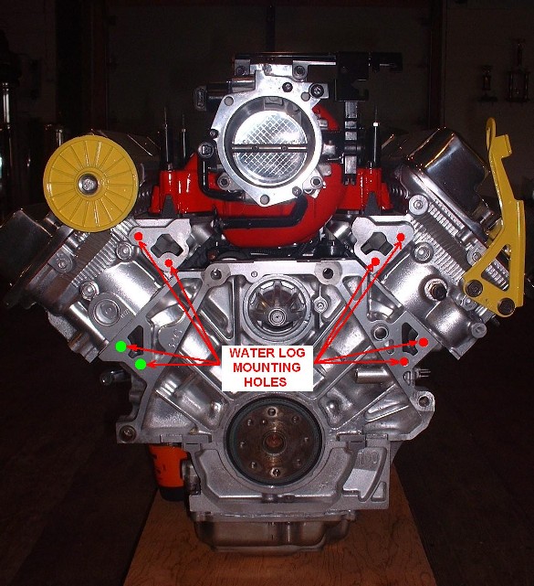
The next step involves having some RTV handy since some of the water log mounting bolts penetrate into the water jacket. I was curious to which ones needed the RTV and decided to shine a light into the four mounting holes on the engine block and the four in the cylinder heads to see. I was surprised to find that only two of them did, so I imagine GM specified RTV on all of the bolts to make things easy on the assembly line. The two that needed it on my block are the ones highlighted in green, the red ones were fine, but I applied RTV to all the bolt threads just in case:
Apart from the boltholes, the way the water passages seal up against the block and heads is with a metal gasket that has a neoprene-like seal embedded on both sides. It’s a little tricky to get all four seals on the log and get it up to the block without the seals falling all off since nothing captures them. The trick is to slide all eight mounting bolts through the log and hang the seals on them.
Another complication is that you must hang the little water pump belt off the cam pulley and make sure as you raise the log up to the engine, that you slip the water pump pulley into the belt loop. If you don’t do this, you’ll soon find out that there isn’t enough room between the snout of the pump pulley and the block to install the belt. I know this first hand. Needless to say, lifting this contraption up to the block took two hands so there aren’t any pictures of it going into place. Here it is though, in the process of being torqued down. All eight get torqued to 18 lbft.
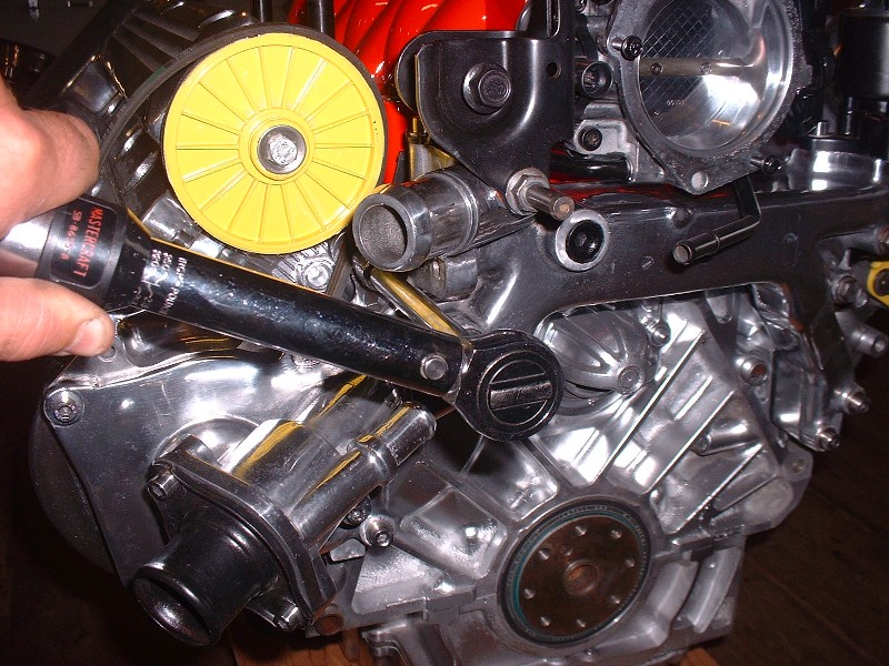
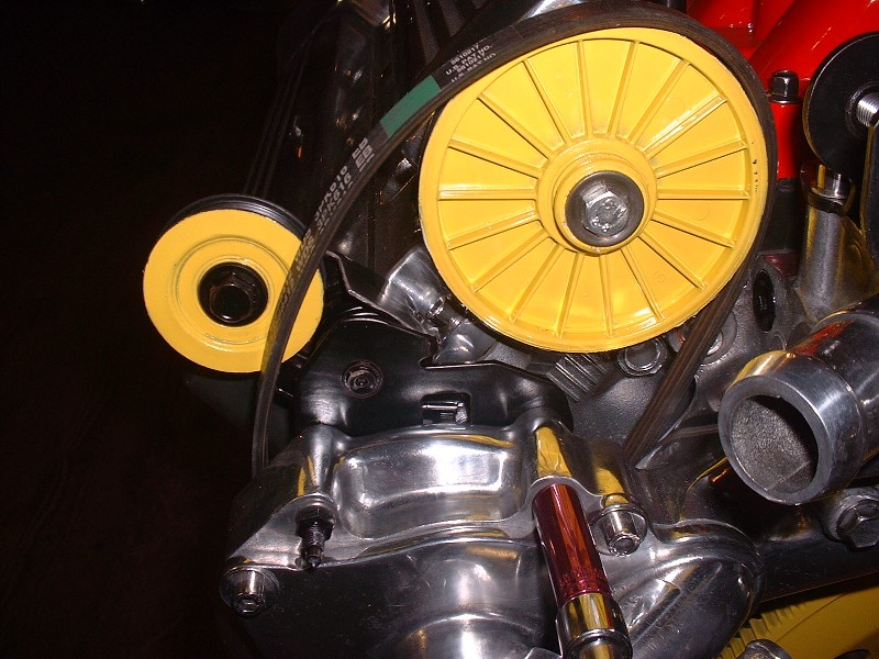
Next up is the little water pump belt tensioner. In this series of three photos, the first is mounting the tensioner to the log with two long, small diameter studs. (Notice the space between the tensioner pulley and the cam pulley at this point).
This photo shows how you "lever" the tensioner pulley against the force of the tensioner spring towards the cam pulley, by using a ¼” drive socket-wrench in the handy-dandy little ¼” square hole on the back side of the tensioner arm. Notice how much closer the tensioner pulley is to the cam pulley?
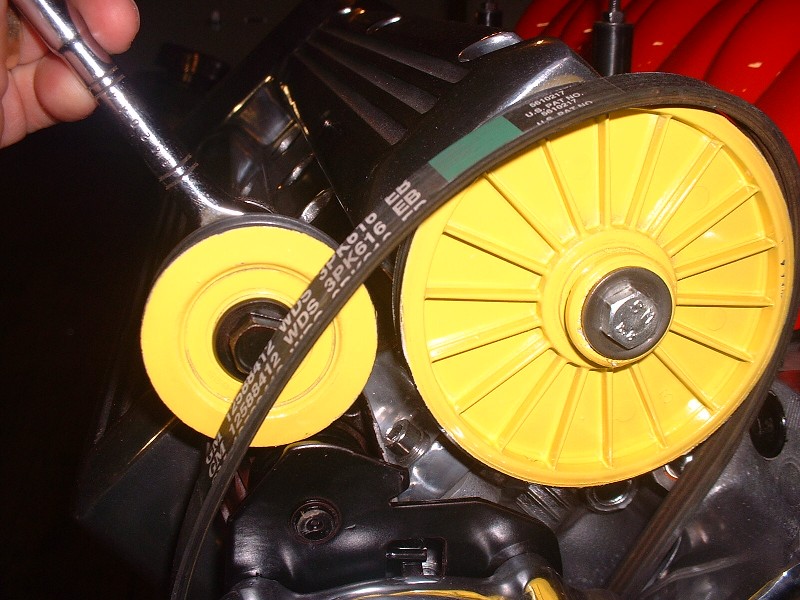
With the arm fully retracted there’s enough slack to slip the belt on the tensioner pulley, and from there it’s just a matter of releasing the pressure on the tensioner. It’s easy to get the belt on crooked as I found. I had to re-take this picture after coming back to the office, downloading the photos, and seeing that the belt wasn’t properly seated on the cam pulley. Good thing I noticed before trying to start this puppy up! This is with the pulley on properly.
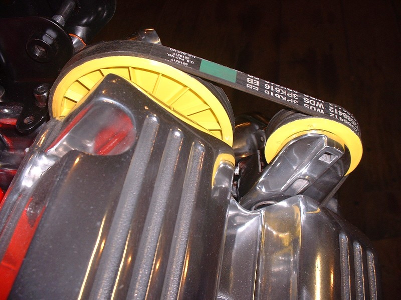
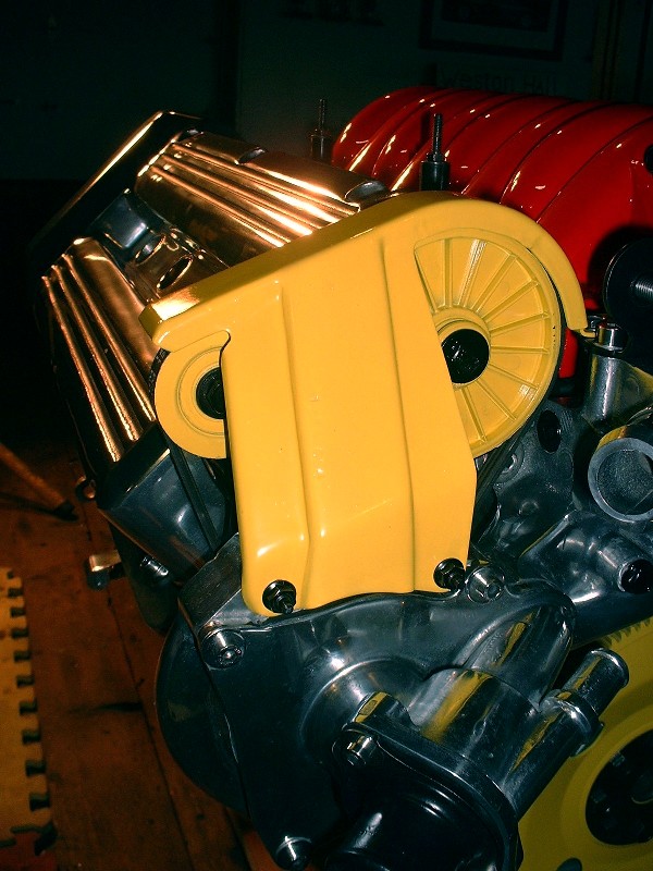
Finally to keep those probing fingers safe from whirling belts and pulleys, here’s the little pulley guard that mounts to the free end of the two tensioner mounting studs mentioned earlier.
Originally posted by Bloozberry: for Topcat, there's no magic formula to keeping the aluminum nice and shiny that I've found so far. The corrosion forms in the pits, so sanding and polishing takes care of a good deal of the problem. The quality of the aluminum also makes a big difference though. I've polished the intake plenum on my TPI small block only once and over 14 years it's never oxidized. On the other hand, I polished my 2.8L plenum on my '86 and had a tough time keeping it looking good. Last year before storing it for the winter, I repolished it and tried spraying it down with WD40 to get a protective film on it. It worked great but it left me with a different mess to clean up in the spring, though it's far easier to wipe off the WD40 than to try to clean off oxidation. I may try using car polish (carnuba wax) in an attempt to keep the pieces from tarnishing on the N*. The polish should fill in any voids preventing moisture from getting into the tiny surface imperfections. I'm keeping my fingers crossed that the engine block is made of the same alloy as my TPI plenum, but so far it looks like it's not.
There is only 1 way to keep polished Aluminum look good after your done and have the part powder coated clear afterward. That will seal in the finish and not let it oxidize. But you run the risk of any oil embedded in the part coming out afterward causing a nice blemish. I am yet brave enough to PC clear any polished aluminum parts yet.
------------------
**************************************** Found a 88 formula Waiting to get a fence so I can re-home it There are Two kinds of Fiero's : Notchies and Donors!
I forgot to mention a big milestone I reached in the last post in terms of engine rebuilding. I finally moved the engine from the stand to a floor dolly. Yay! It had to be done in order to install the water log, since the engine stand gets in the way. I also couldn’t install the rear crank seal with the engine on the stand either.
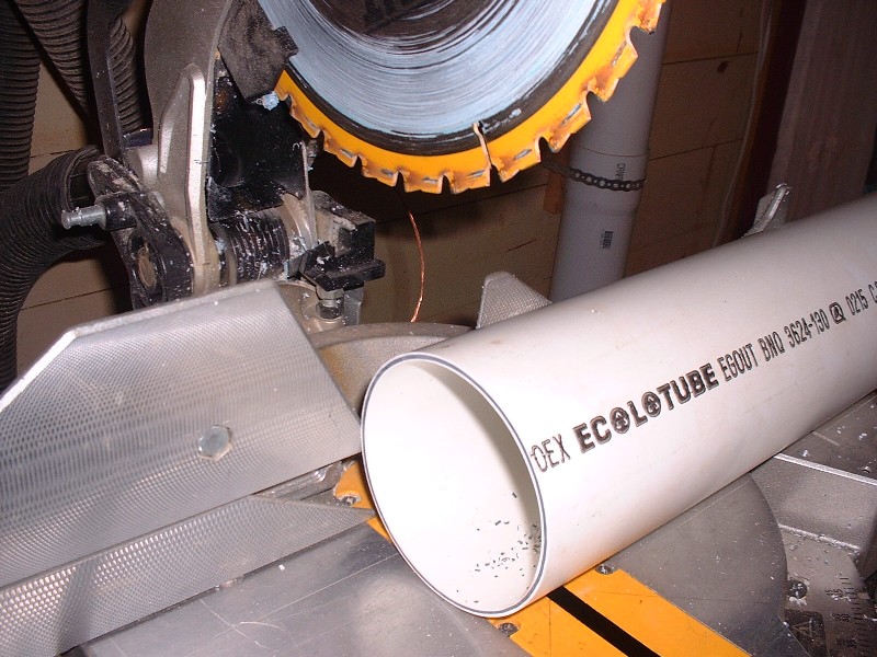
I didn’t get any pictures of the rear crank seal by itself, but the seal is quite innovative in that it’s actually a combination metal sleeve and a typical elastomeric axial shaft seal with a garter spring. The metal sleeve gets driven onto the crankshaft flange with an interference fit, renewing the journal surface on the flange that the old seal rode on by covering it up. The new seal is sized for the diameter of the sleeve, not the diameter of the crank flange. The sleeve and the seal are inseparable since the sleeve is formed with small flanges on both ends at the factory once the seal is slid on. It’s great because your new seal isn’t riding on the old worn surface. The trouble is that to get the sleeve pressed onto the crankshaft, you need to buy, rent, or make a special tool. Stealing an idea from PFF’er WAWUZAT, I made a tool from a piece of 4” PVC drainage pipe and some 1/8” cold rolled steel plate. I cut a piece of the PVC pipe about 2” in length:
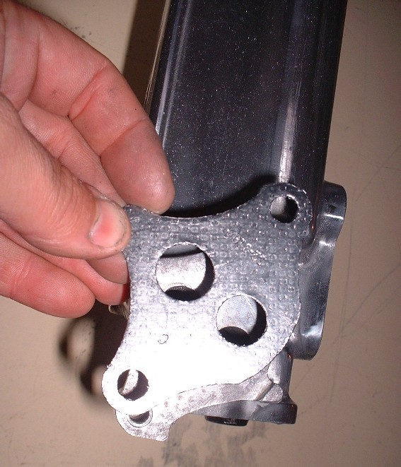
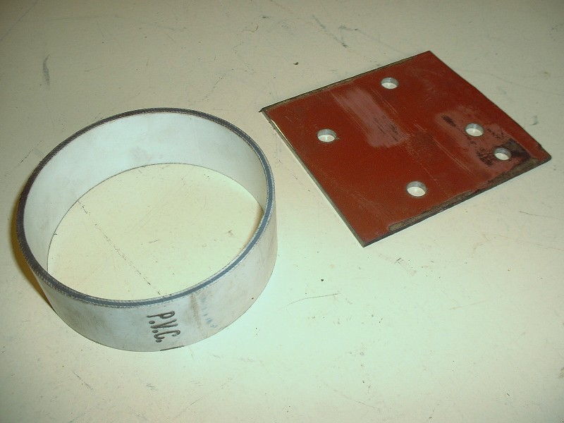
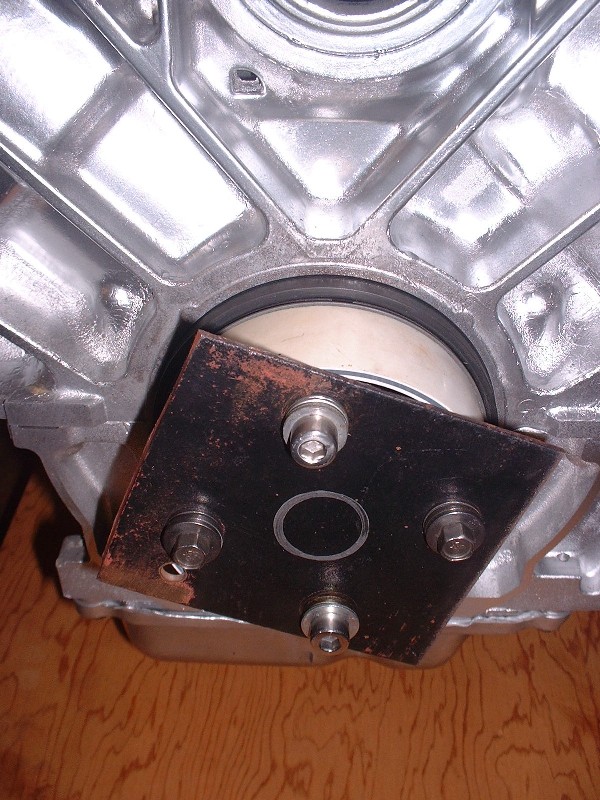
The PVC pipe is exactly the right diameter to contact the outer sleeve flange of the seal assembly. So, to be able to apply even pressure to the pipe while installing the sleeve, I used the Caddy flex plate spacer to trace the outline of four of the eight crankshaft bolt holes onto a 4” X 4” piece of steel plate:
Then, by using the metal plate on top of the pipe, along with an assortment of bolts and washers, the sleeve and seal assembly can be pressed onto the end of the crankshaft squarely and under control by tightening the four bolts. The instruction that comes with the seal state that it must be installed dry, so don’t use lubricants here. You must be careful not to bottom out the bolts as you draw the seal into place because the holes in the crankshaft flange go completely through the flange. Immediately behind the crank flange is the rear bearing cap, so if you’re not careful and end up side loading the cap, you’ll warp it. To prevent this, I kept removing the bolts and adding more washers under the heads as the seal inched into place.
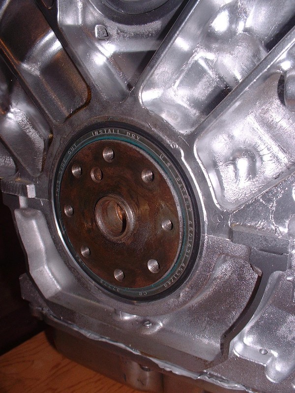
You know you’ve seated the seal/sleeve to the proper depth once it’s past the end of the crank flange by about 1/16”. Here’s a close up of the final product:
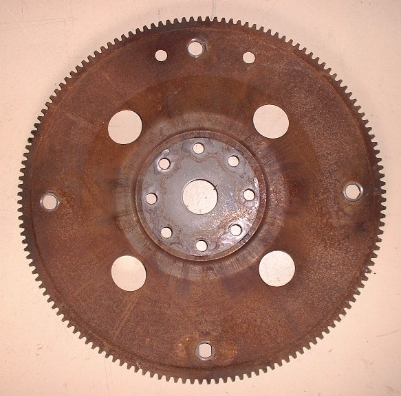
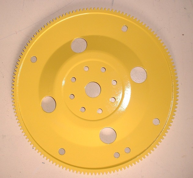
For the clutch/flywheel stack, I plan on using the Caddy flex plate as the starter ring gear, with a spacer sandwiched between the flex plate and a dual mass flywheel. The thickness of the spacer will be determined once I’ve bought the rest of the parts like the pressure plate, friction disk, and flywheel, none of which I have at the moment. But that didn’t stop me from prettying up the flex plate in the meantime.
I bead-blasted it…
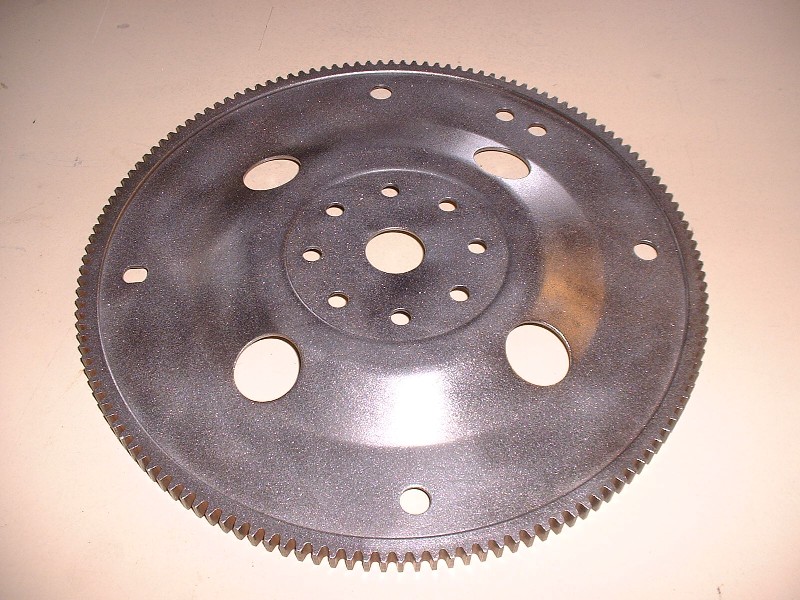
Then shot it with a white undercoat, and finally some more of that John Deere yellow paint.
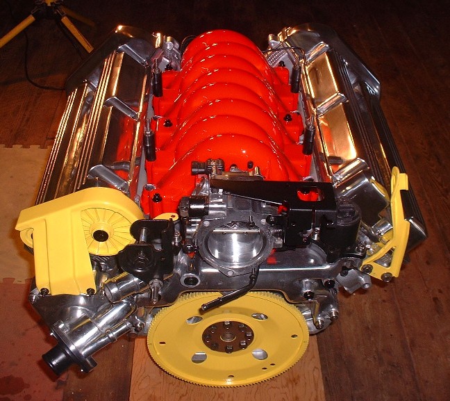
Then I temporarily installed it to get it out of the way. For good measure, I made two marks on it in line with the case half as a reference point for #1 TDC just in case the cranks turns a little while installing the front end pulleys and belt later on.
Next up: the front end hardware (or I guess that'd be the RH hardware on a Fiero). I’ve done a fair bit of research in older threads about belt routing and found some interesting stuff on relocating the serpentine belt tensioner to where the old power steering pump was up on top of the engine in the middle. So far though, all the threads I’ve seen use AC, something I don't plan to run since my car wasn't orignally equipped with it. I’ll ask here and also start a new thread in Tech asking the same question since it’ll probably get a wider audience there: Has anyone got an example of how they routed the belt on a N* without the AC compressor?
[This message has been edited by Bloozberry (edited 10-04-2010).]
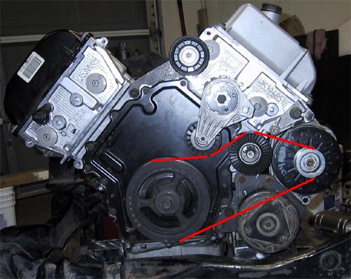
Originally posted by Bloozberry: Has anyone got an example of how they routed the belt on a N* without the AC compressor?
If this looks like yours, the ac is the bottom right. You should be able to just get a shorter belt. Use a piece of string and follow the route to get the length.
Thanks Gokart Mozart, but I also want to ditch the power steering pump too, I guess I should've been more clear. Referring to the diagram you posted, I want to relocate the tensioner (like many others have) to where the PS pump is (at the top), and eliminate the AC compressor. I know it's not rocket science, I'm just wondering if anyone else has done this that is willing to share a picture.
Edit: On second thought, I guess I'll just relocate the stock stationary idler to where the PS pump is (maybe even convert the pump into the idler similar to what IXSLR8 did), leave the tensioner in the stock location, and ditch the AC. So going clockwise from the top of the engine, the belt would come off the new idler, around the alternator, to the crank, then to the tensioner in the stock location, and back up to the new idler. That settles it. I'm good to go.
[This message has been edited by Bloozberry (edited 10-05-2010).]
Thanks for the idea Jef. I'll see if it's feasible... the only potential problem I see is that since the alternator pulley is quite small in diameter, having the tensioner pushing up on the lower belt may place it too close to the upper side of the belt for comfort.
(Edit: BTW, +'s for both of you Gokart and Jef)
[This message has been edited by Bloozberry (edited 10-06-2010).]
Or leave the alternator and use the aircon mounting hole for a custom bracket to support a tensioner. This way you will have low maintenance, but more important, have a short belt that is tucked away out of site. I would hate to see your beautiful engine spoiled by an ugly pulley and belt loops at the top.
I don't know if anyone has looked at this but it may work. Not the optimal angles for either the tensioner or the alt but not too far off. The lower bolt on the alt pivot mount would probably require modification as it protrudes into the belt approximately 1/16". Please ignore the top idler and the ac compressor.
I think your proposal will work. What you want is maximum belt contact on the traction pulley surfaces (crank & alternator) and minimum traction on the idler and tensioner pulleys and you have almost 180 degrees on the alternator.
Well, I’m pretty sure I’m going to route the serpentine belt in accordance with Charlie's (cptsnoopy’s) suggestion, but I’m only going to commit to it once I get all the parts polished and can test it out. So that means only one thing… more painting and polishing!
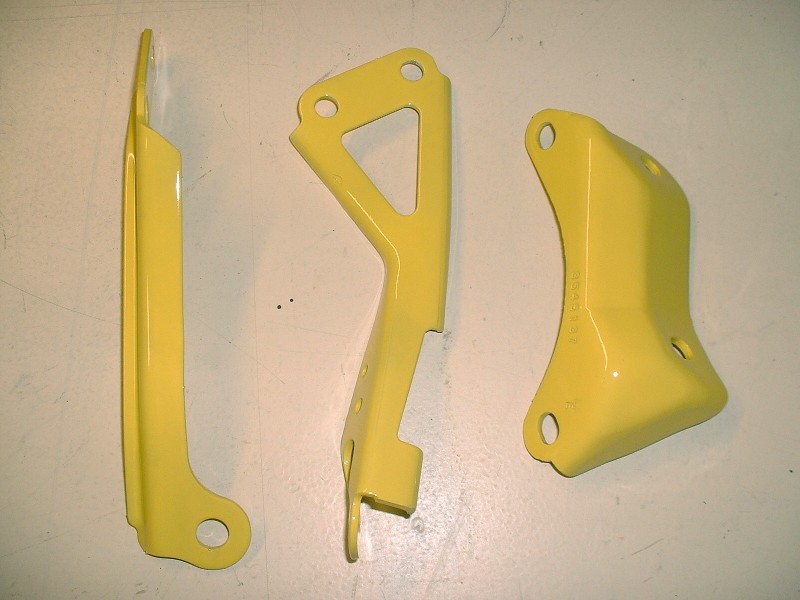
On the painting side of things, here are a few engine brackets that needed refinishing… some I know I need, others, not so sure but I was on a roll with the sandblaster. I just hope I don’t change my mind on the color of the car over the next year or so (although some of you probably do!)
Next up was the serpentine belt tensioner since I knew I’d be using it regardless of the belt routing. So off came the pulley, where it got treated to a varsol bath, and the rest of the tensioner got thrown into the sandblaster. Once good and clean, the tensioner got the rough-medium-fine flapper wheel treatment, some extra fine hand sanding, and finally a good buffing on the wheel. While that was going on, the pulley got undercoated white, then sprayed with some color. Here’s the finished product… better than new!
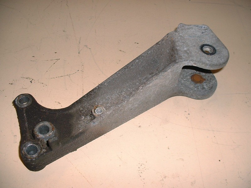
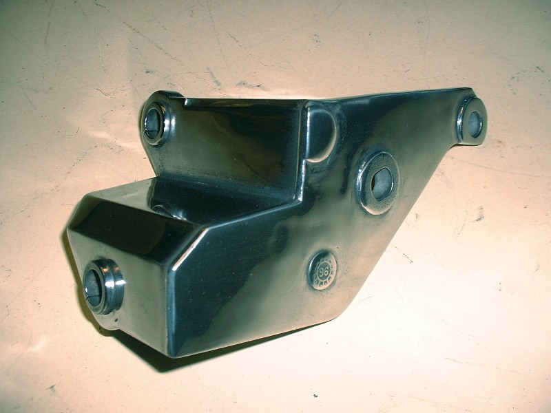
Again, I’m unsure whether I’ll be able to make use of the stock dogbone mounts on the engine itself, but my plan is to use them if at all possible. I’d rather have the dog bone(s) on the forward firewall where they’re less obvious than on the trunk wall like most people have them. I won’t know if I’ll have the space or not for another week or so when I test fit the engine but in the meantime I figured I’d schnazz up the RH one to help motivate me to use it no matter what the obstacles. Here’s the “before” picture:
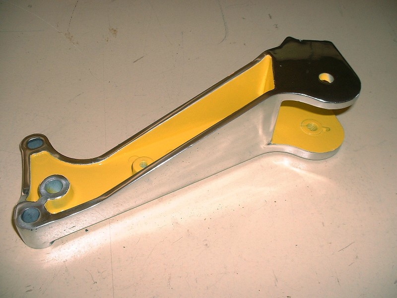
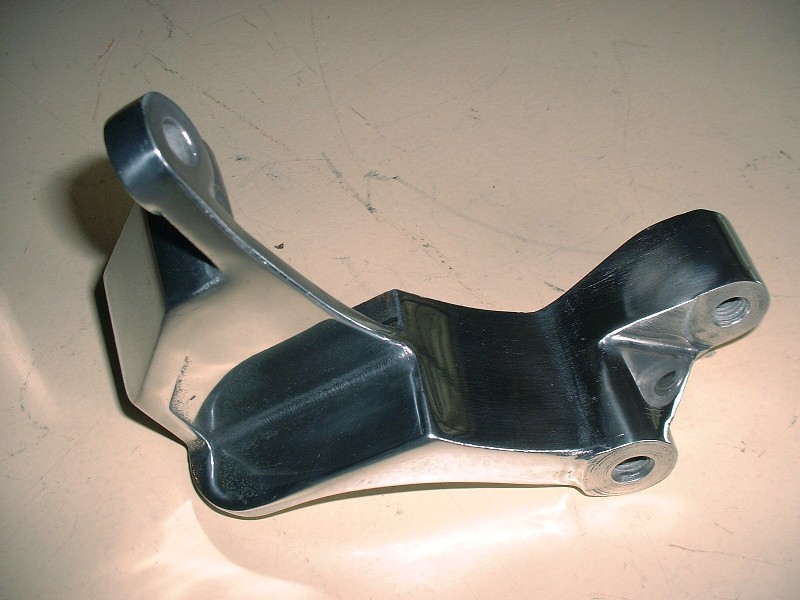
And here’s that “after” picture. Since my engine bay is deeper by 3” due to the chassis stretch, I have good reason to believe that I’ll be able to adopt my front dogbone idea into my car. On this bracket, it simply wasn’t possible for me to get the pebble finish of the sand casting off the recessed areas. I couldn’t figure out how to polish in those areas either so I left them rough, and painted them instead. I think it adds a finishing touch to an otherwise difficult piece to polish.
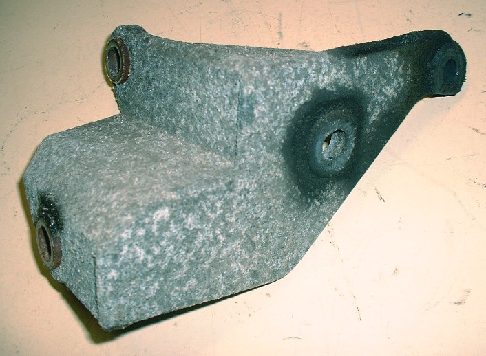
My heart kind of sank as I reached into the tickle trunk to see what my next task would be and pulled out two more aluminum brackets. Arghhhh… will the polishing ever end? It turns out that the Northstar alternator is held in place with not one, but two brackets. Here’s what one of them looked like in a typical crusty finish.
A bunch of elbow grease, a lot of patience, some buffing compound up my nose, a couple hours, and here’s what the two brackets came out looking like... this is the rear one:
And this is the front one:
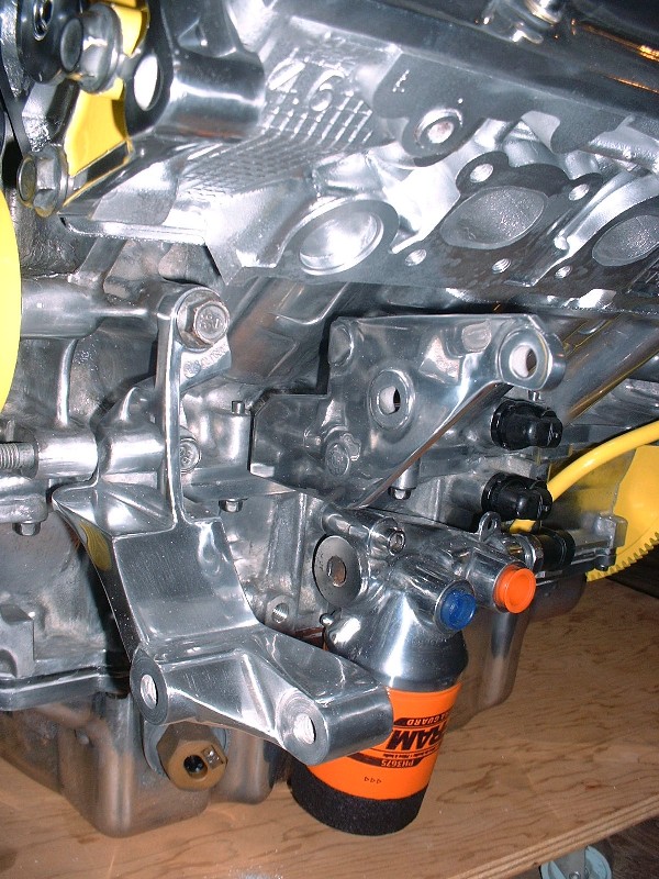
With those done, I could finally install them…
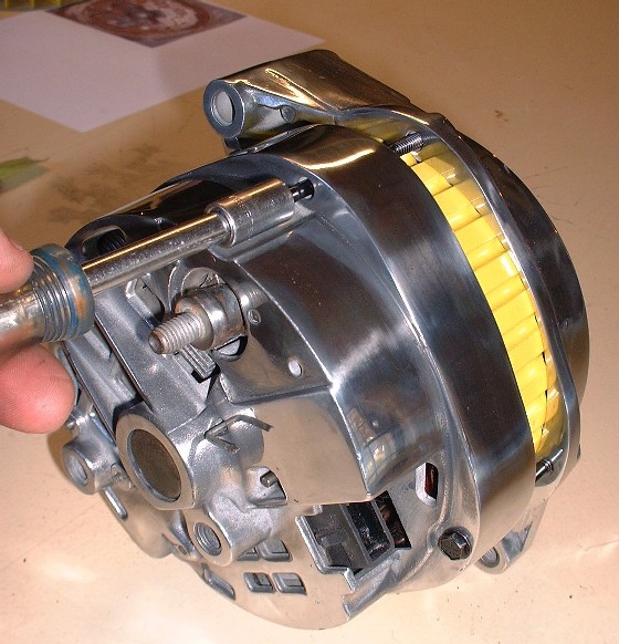
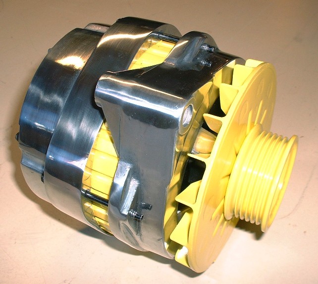
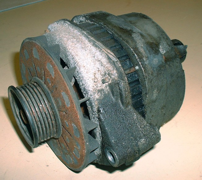
…and move onto the last piece needed to complete the front serpentine belt system… the 140A alternator. That should be easy right? Except good ol’ Murphy (from the Law society) has taken up residence at my place for some time now and made his presence felt again. I figured I would just be able to take the alternator apart, polish the case, and stick it back together again. That was wishful thinking...
Anyone recognize the symbol? It sure looks like the Briggs and Stratton logo to me.
Most GM harmonic balancers are Briggs and Stratton. You can also find the same logo on the 3800's balance shaft.
From the early days of GM till... I think '67 GM's Keys were Briggs and Stratton as well. If you see the Hexagonal head on a classic cars keys, thats a B&S ignition key.
Now, on with the show. The engine is looking absolutely beautiful. I am very impressed with your workmanship. Doin' us proud.
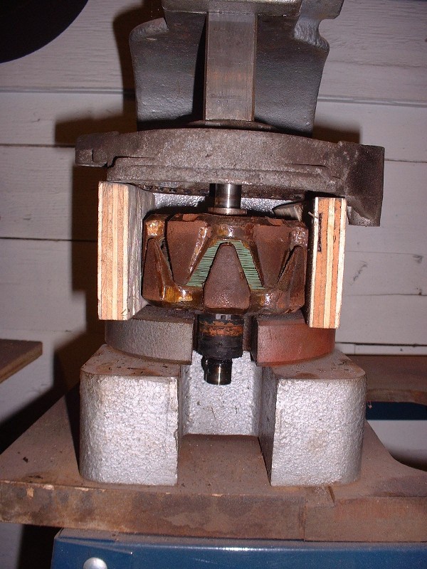
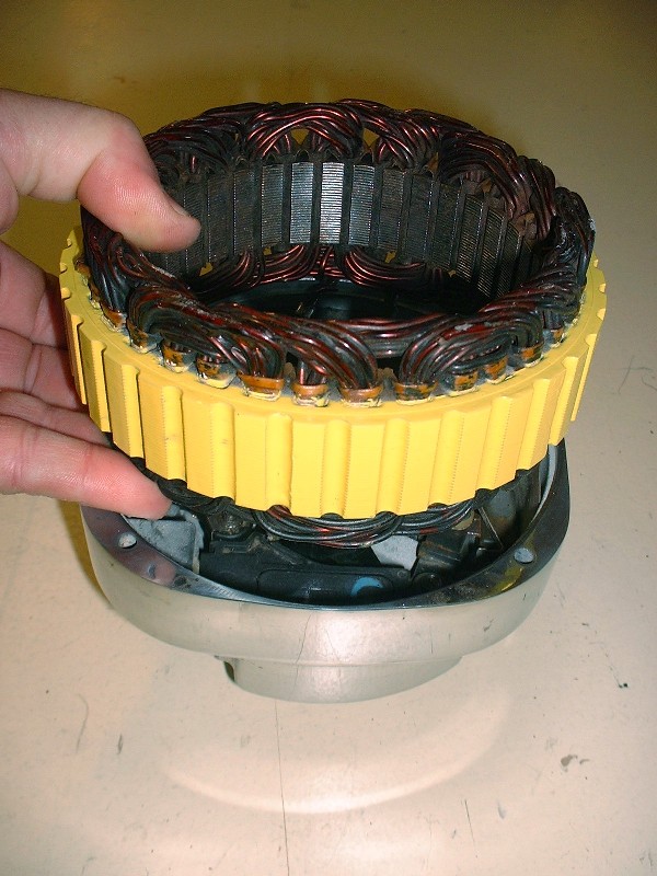
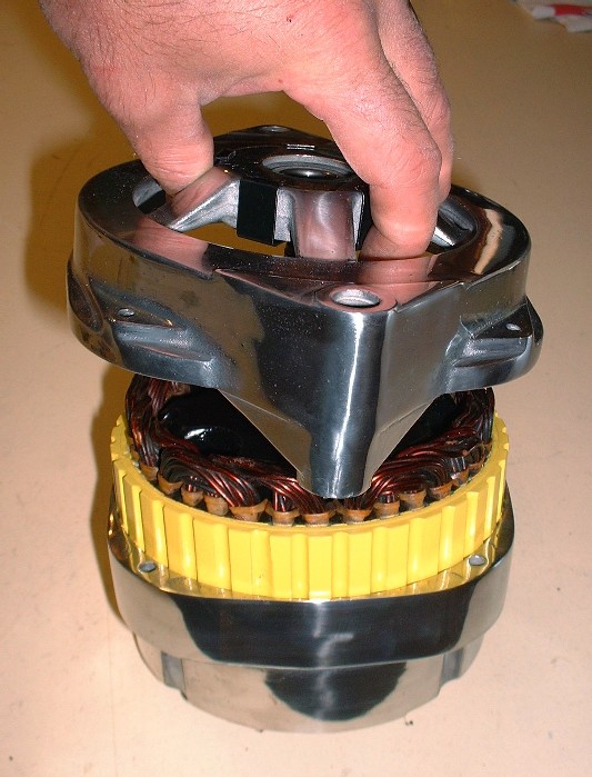
I wanted to polish the alternator case so that meant taking it apart. (I know for many of you rebuilding an alternator may be uninteresting, but if this helps one person in the future, then it was worth it. The rest of you can scroll on by!) There are only four screws that hold the case halves together, and once they’re out, the alternator literally comes apart in four major sections excluding the fan and pulley. To get the armature/rotor to let go of the bearing in the front case halve, I had to press it off with my arbor press.
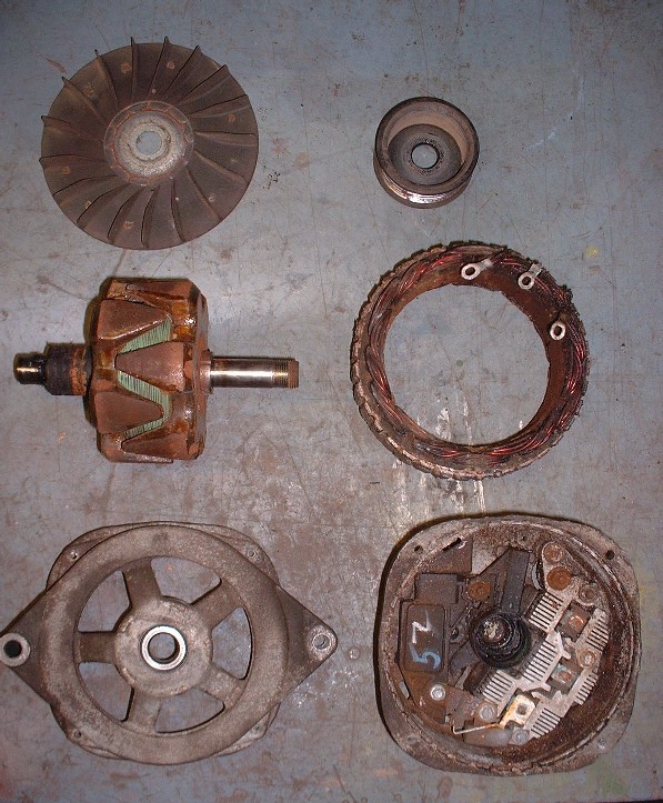
Here are the major parts clockwise from the top left: fan, pulley, field windings, rear case half, front case half, and rotor/armature:
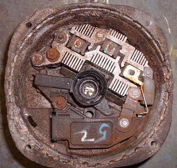
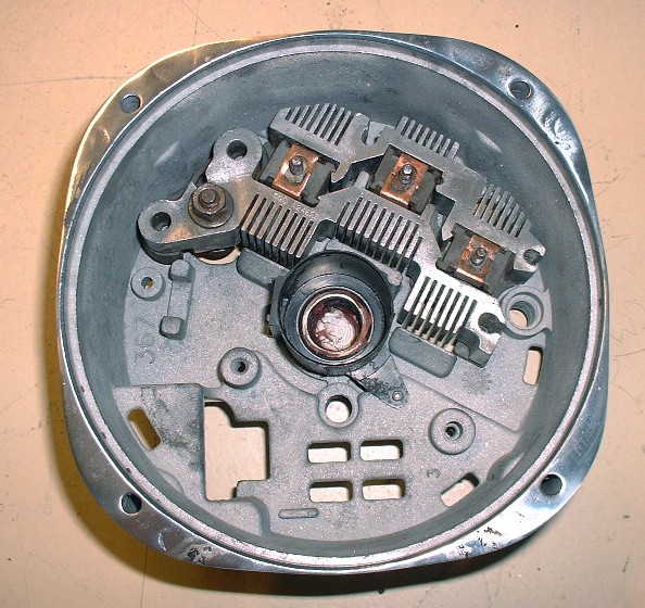
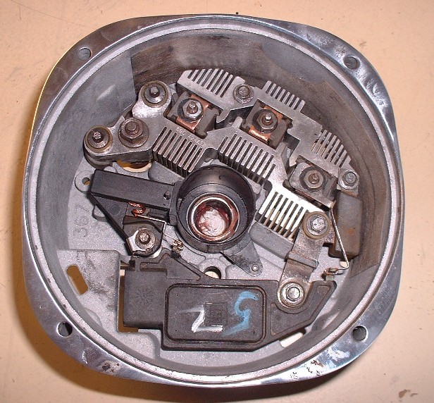
Because I don’t have a rebuild manual for this specific alternator, I took a close up picture of the layout of the electronics in the rear case half to make putting it back together a little easier. Good thing I did too because I needed to refer to it several times.
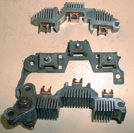
I removed all the components so I could clean, sandblast, sand and polish the rear case without worrying about ruining something. Once the case was polished, I cleaned the individual parts of the voltage regulator, rectifier, and heat sinks and reinstalled them. To be honest, I haven’t a clue which part is which so I won’t even pretend. Here’s the part with the heat sinks. There are two sets and they snap onto a plastic insulator mount of sorts:
Once they’re back together, they can be set back into the rear case.
Next in the order of reassembly comes this doo-hickey… again, for now it just gets set into place:
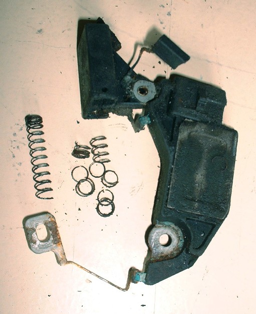
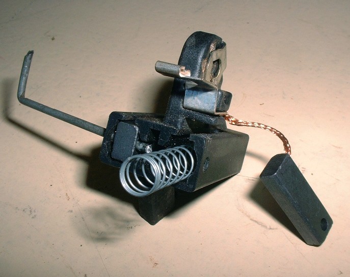
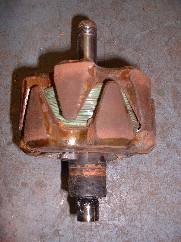
And here’s where my problem started. As I was taking apart the alternator and inspecting the various pieces, I noticed that the armature where the brushes ride was worn asymmetrically. When I removed the brush assembly, this is what I found:
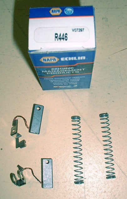
That’s when I almost cried because I wasn’t aware that you could buy the brushes separately, and a rebuilt alternator is $230! After a few calls to the dealership (I don’t know why I bother) and some local parts stores, I learned that for $5.77 I could have new brushes the next day! Yay! I got these from NAPA:
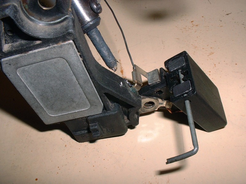
Installing the new brushes was pretty straight-forward, but for anyone who hasn’t done this sort of thing before, you basically insert the brushes into a holder, then slip a small diameter pin (I used part of a bicycle spoke) through a couple holes in the holder and the brushes to keep them from springing out. Here’s one side that’s done and the other just waiting to be pinned in place:
One of the brushes was originally soldered onto a tang that protrudes out of the solid state box, so I did the same with the new brush too. Here you can also see how the pin keeps both brushes tucked inside the holder until you’re ready to release them.
And with that, I’m off for the weekend flying to Ottawa to catch Roger Waters perform Pink Floyd’s The Wall. Yes… this should be awesome.
What fun! That is one of the movies that I recorded on vhs and watched at least 6 times. I guess you won't see the incredible animation at a concert, but todays kids being used to digital animation are probably not impressed anyway. Now I'm envious of you for that too!!
I’m back… and feeling comfortably numb. What a show, simply awesome. I looked for a Fiero in the parking lot (all 30,000 cars) but didn't see yours there BtotheB! As for Dratts... I can't remember how many times I've seen the movie, each time figuring out a little more of the meaning behind it all. My brothers and I rented it again and watched it as a primer on Sat night... I still like the girl with the pink pants! BTW, the graphics were first-rate during the show... turning a 250' wide white wall into the world's largest HD wide screen TV.
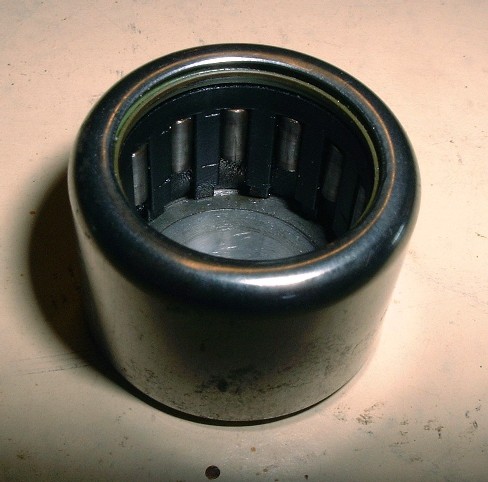
But back to business… I popped out the needle bearing when I took the case apart, cleaned it with varsol, blew it dry with air, inspected it, and decided to re-use it after suitably greasing it back up with clean synthetic grease.
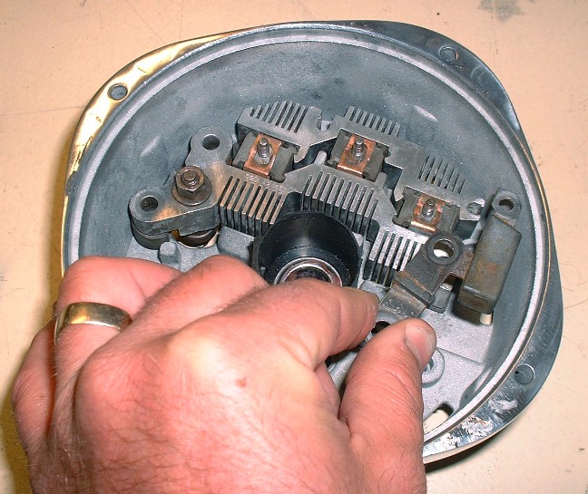
I used my arbor press to squeeze it back into the rear case and then focused on installing the remaining electronics. Here is everything installed in its proper place. When I installed the brush assembly, I had to remove the pin, hold the brushes in place with one finger, and reinsert the pin through a little hole in the back face of the rear case made just for this purpose. I actually got a little ahead of myself in this picture. If you note the two nuts between the 12 and 1 o’clock positions on top of the copper strips, and a similar nut at the 3 o’clock position, well, the three eyelets from the field windings are supposed to go on those studs before the nuts go on, so I had to take them off.
Here are the field windings being installed. Not visible in this photo are the three wires with eyelets on them that attach to the three studs mentioned above. The windings themselves are countersunk into the rear housing by about 3/16”. Notice a trend in the color?
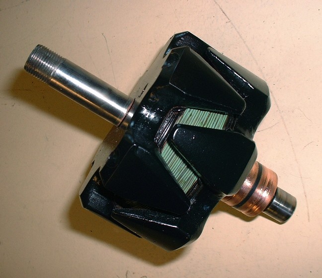
Once the field windings are in, the armature/commutator assembly needed a little attention. Here’s what it looked like before the make-over:
And after:
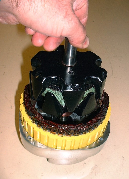
Once ready, it just gets lowered into place with the end of the shaft seating in the needle bearing that was installed earlier. At this stage, don’t forget to reinstall a thick spacer washer on the free-end of the rotor shaft. It serves as a thrust washer against the inside of the front housing.
Next up is the front housing which needs to be clocked in the proper orientation with respect to the rear housing if you want the electrical connections to be accessible once it’s installed on the engine. When looking at the front of the alternator, place the thickest of the two ears on the front housing at the 3 o’clock position, then line up the large lug for the positive battery lead on the rear housing at approximately the 1 o’clock position.
Then reinstall the four housing screws and torque them to 60 in-lbs.
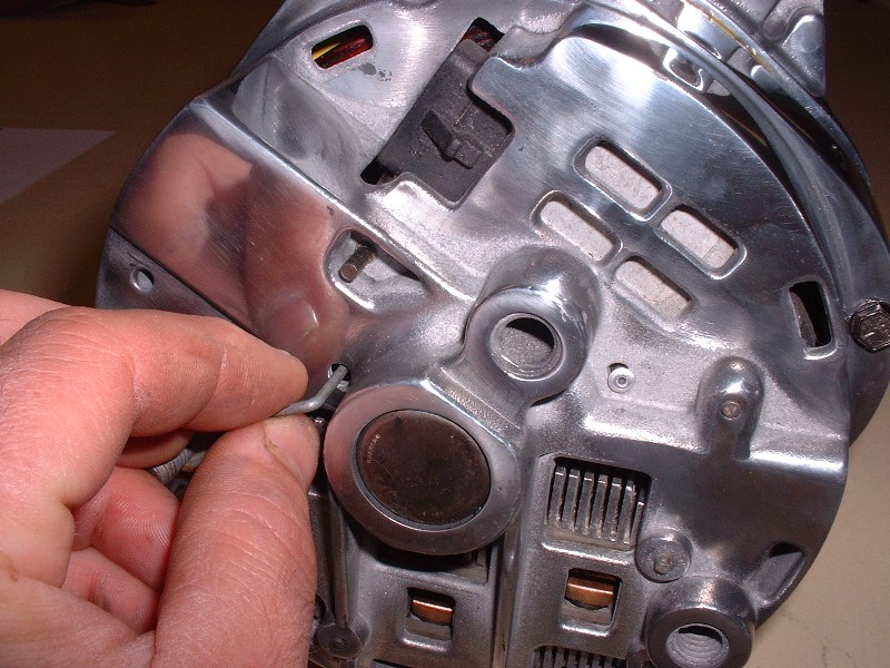
With the two halves back together again, it’s time to pull the pin out of the back of the alternator to release the brushes, like so:
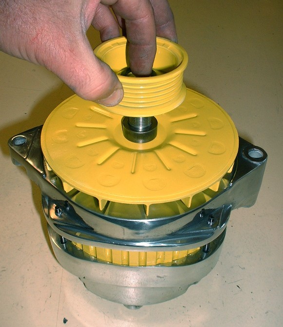
The last step is to reinstall the front end components in this order: thin spacer, fan assembly, thick spacer, pulley, washer, then nut. I used my impact wrench set on medium to tighten the nut.
And voila! A far cry from what it looked like before.
Regarding the girl in the pink pants. I'm pretty sure I know the one you are talking about and it's been a while since I watched it. In fact it's on vhs and I don't even have a vhs anymore. She was a groupie right?
Thanks Mattwa. There's a couple of considerations when deciding what to do to keep the aluminum shiny. The most important is polishing the part as best as you can. That means sanding out all of the little pits in the surface since that's where the corrosion starts. The next thing is being able to tell whether the part is aluminum or "pot metal" (aka white metal) which is just a blend of all kinds of scrap alloys melted together and cast in a very porous state. Sometimes it's hard to tell which is which, but usually the aluminum is denser and just "feels" like a better quality part. For aluminum, corrosion isn't usually a problem if the parts stay dry. I'm using a coat of a good quality paste car wax on these parts. This fills in any of the pores to seal them off. For the pot metal parts, there isn't much other than a coating of WD40 that keeps them shiny. The metal is just so porous that even when you sand it, you break into tiny cavities that are everywhere under the surface.
Clear coating may work for aluminum but it won't work very well for pot metal because of the porosity. It's very hard to get the polishing compound out of the tiny pores in the surface, so the clearcoat "fish-eyes" when you try to apply it. The other problems with clearcoating though, are that the moment gasoline touches it, it turns yellow, and anywhere that a bolt must be tightened down over-top of the clearcoat, it breaks through the protective coating and the corrosion starts from there.
Polished parts need regular maintenance, but if you're starting off with quality aluminum rather than pot metal, you'll have way less work to do to keep it shiny.
(Edited for spelling)
[This message has been edited by Bloozberry (edited 10-21-2010).]
Clear coating may work for aluminum but it won't work very well for pot metal becasue of the porousness. It's very hard to get the polishing compound out of the tiny pores in the surface, so the clearcoat "fish-eyes" when you try to apply it. The other problems with clearcoating though is that the moment gas touches it, it turns yellow, and anywhere that a bolt must be tightened down over-top of the clearcoat, it breaks through the protective coating and the corrosion starts from there.
Polished parts need regular maintenance, but if you're starting off with quality aluminum rather than pot metal, you'll have way less work to do to keep it shiny.
You can powder coat the parts with a clear and it will protect the "shiney "
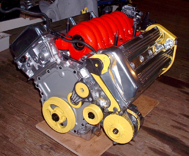
With all the front mounted accessories finally polished and/or painted, it was time to install them so I could take a few measurements for my new serpentine belt. When I started to wrap the stock belt around the pulleys to do this, I realized that the stationary idler pulley would need to be changed out for one with grooves. I’ll need to go scour the scrap yards one of these days if the rain and freezing-cold wind ever stop. Here’s everything installed, at least temporarily, with the wrong idler pulley.
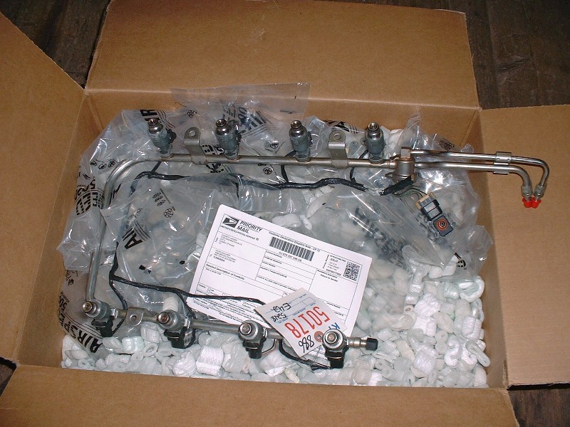
A couple weeks ago I started surfing eBay for a stainless steel fuel rail and came up with one from an Oldsmobile Aurora for $50 including the injectors, pressure regulator, MAP, and harness. I probably could have gotten it for cheaper but I decided to use the “Buy it Now” button since I figured it was a good deal as is. It arrived a couple days ago and except for the electrical connector having been cut off, it was in good condition. I don’t need the connector since I already have one from the old plastic Northstar rail.
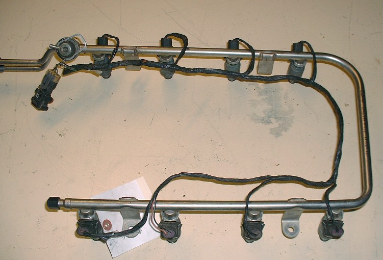
I wanted the Aurora rail because the fuel connections are on the forward bank of the engine rather than on the aft bank in the stock Northstar configuration. Both are still at the transmission end, which means having to lead the lines over to the passenger side of the engine bay but at least with the Aurora rail I won’t have to lead the fuel lines forward since they’ll already be on the correct side of the engine.
The Aurora rail has it’s own set of challenges though. It can’t be installed directly on the Northstar without removing the dog-bone mount at the transmission end of the engine since the fuel rail interferes with it. The ends of the rail also have an up-turn so I will cut off the ends to kill two birds with one stone. I haven’t decided how I will couple the rail to the car’s fuel lines yet but I recall a post where someone was able to use some AN fittings from Russell. More on that once I do some more research.
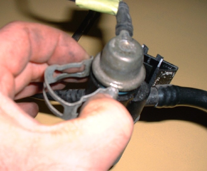
Since I wasn’t entirely sure the Aurora rail had the same fuel pressure regulator or that it was set at the same pressure as the Northstar, I swapped them around. To remove it from the rail it’s a simple matter of pulling off a retaining clip with your fingers (this one is on the old plastic rail)...
…and pulling up on the little regulator. It’s a good thing I decided to swap them over because the inside of the regulator on the Aurora rail was partly rusty and very gnarly-looking. If you do this yourself, be aware that there’s a large o-ring on the regulator OD, then there’s a very fine plastic fuel filter, and deeper inside the housing part of the rail, there’s another tiny o-ring that seals against the little tube at the bottom of the regulator. Sometimes the filter stays inside the housing, but the tiny o-ring almost always stays inside it.
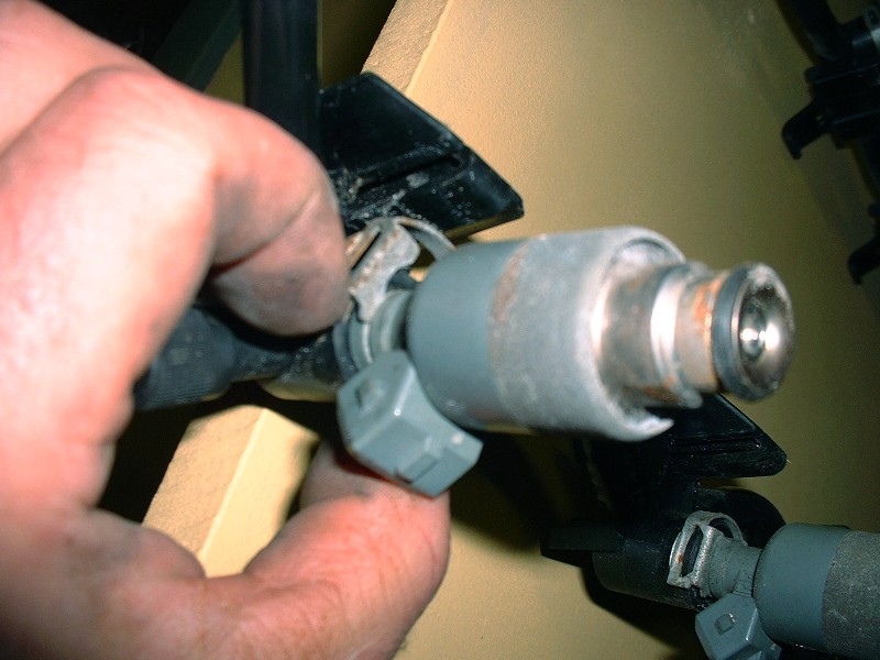
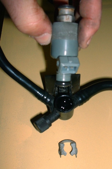
I haven’t decided yet whether to replace the injectors or try to get them cleaned. Where I live, I haven’t yet found a shop that can clean them unless they’re installed in the car, which makes the whole process moot if I have to drive there first only to burn up a piston and some valves. I may have to break down and buy some new ones for peace of mind. PFF’er Will mentioned that there are inexpensive Ford pieces that are direct replacements. Regardless, here’s how you take them off the fuel rail… first, you have to pry off a stiff little metal clip at the top of each injector…
…and then you have to pull pretty hard on the injector to get it to let go of the rail. I’d say about half of the time the upper injector o-ring stayed in the rail rather than come out with it, so have a good look to be sure you have them all out. After they were pulled out of both rails I noticed that the injector part number is the same for both the Aurora and the Northstar rails. I would have figured the Aurora injectors would be different because of the smaller displacement, so they must compensate with shorter pulse widths instead.


 )
)