I am currently doing basically the exact same thing with a few exceptions.
I have a couple of suggestions for you that you might want to try.
I sent my TB and intake to a company called VmaxMotorsports, they specialize in LS1 stuff mainly, but they port the plastic style intakes for LS1's. When I noticed this, I contacted Pete at Vmax and asked him if he would do a Northstar intake (since they're very similar to the LS1 type). He said he had done a few and would be glad to do mine. Along with that, I sent in my TB and he opened it up for me.
He told me that the LS1s typically see 15-20whp from these mods combined on a stock motor. I know our gains may not be as generous, but as a Northstar modder, it's great to get anything, even if it costs a little bit more for us. From the TB alone after flowbenching it, Pete told me that gained 17.2 cfm over stock. I don't know how much the intake gained, because mine was soaked in carbon and oil build up like yours, but I'm sure it'll be a decent amount. (BTW, I haven't tried cleaning it yet, but I don't think "soap and water and a pressure washer" will be adequate, that stuff is thick and hard to clean! I'm going to try using this thing a friend of mine has called "VAT", it's some really strong chemicals used to clean parts with in a 5 gallon sized jug... it shouldn't hurt the plastic, but hopefully will clean up the majority of the buildup inside of the intake).
It cost me $430ish? plus shipping to get these mods done. The application is a 4.6 being swapped into a 95 Aurora. Among other things going in the motor (very similar build to yours) will be CHRFAB 272 cams, Wiseco .020 over pistons, Eagle rods, and worked heads. Planning on tuning with Westers.
I decided to go with the lighter lower end parts (the Wiseco Pistons and Eagle rods) because according to my math, there is a 2-3 pound weight difference, maybe this will make a noticeable difference in the performance of the motor (it better!).
I'd like to get this intake/TB setup on a stock 4.0 Aurora and dyno it, to see what the actual gains are. I really dig that gasket job on the Oil manifold on your motor... where did you come across that technique? I've been racking my brains to try and figure out what to do when I get to that point. If you have a write up on it or anything specific I'd love to see it.
Thanks for the comments katatak, fieroguru, and bamman. Bamman swung by my place about two weeks ago with his 4.9 powered black coupe... sure sounded nice! I'm not sure I would change that engine even if I won the lotto... your car's a real sleeper.
As for NiNeFiVeFoUrOh (wouldn't it be easier just to write 9540?), that's one nice lookin' TB. US $430.00 works out to about 600 clams up here in Canada after shipping, duty, taxes, and exchange... a bit rich for my already swelled budget! You'll have to post your results once you get your car running. It will be interesting to see how that porting affected overall performance.
You asked about the oil manifold sealant procedure I used. I don't have any other write up other than what's in this thread. But there's no black magic involved... I just couldn't see myself spending the money on a new oil manifold plate when it isn't a wear item. GM probably recommends replacing it because it isn't worth the time and effort for a dealership technician paid at $65/hour to dig out the old sealant. It's a time consuming process that took me a couple hours. Then, I figured the oil manifold plate sees the same harsh conditions as the insides of the case halves, so the case-half sealant should be good enough for the oil manifold too. The part number for the sealant in the US is different than it is here in Canada. For you, the sealant is GM part number 12378521. Just be sure to completely fill and slightly overfill the oil manifold seal grooves with a continuous bead of it, ensuring the sealant is higher than the rail surface by about 3 mm (0.118 in). Be sure to stick it together before 20 mins are up too, or it won't seal properly.
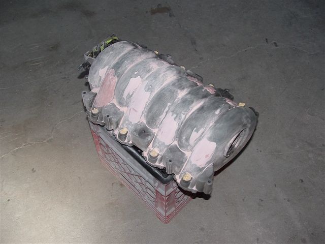
As for a quick update: I finally managed to clean out the insides of the plenum by first dropping it off at my favorite machine shop to get it hot-tanked. They assured me that the solution they used would not melt my plenum, but only after they double-checked with the manufacturer of the chemicals! Once the oil residue was removed, I lightly bead-blasted the interior of the runners and the insides of the main central part of the plenum with very fine glass beads. It worked like magic, removing every bit of carbon as far as the eye could see. I used a lower air pressure around 80 psi and the beads just bounced off the plastic manifold without so much as even discoloring it. Lastly, I blew it out really good with shop air. Next, I block sanded the entire intake plenum then ran lots of water through it to ensure it was clean. Today, I dropped it off at the paint shop for final smoothing and color. I'll update with pictures as they become available from the shop. Any guesses what color I picked?
Hey! A new home in the Construction Zone! I like the company in here!
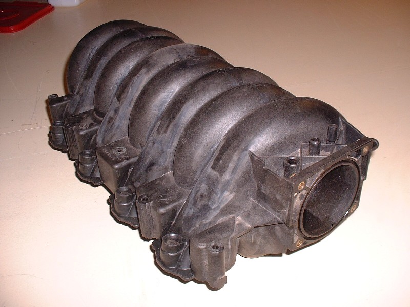
Anyways, before giving the plenum a bath, I figured I’d get some of the messy work done and over with, so I decided to give this porcupine a shave & haircut. Here’s what I’m talking about:
As always, nice work. I hadn't even thought of cleaning up the manifold, and running w/out the cover. After seeing yours, I might have to rethink what I'm doing. I moved my coils to the bulkhead and trimmed the cover to revers it.
Cheers Beers n Gearz. Joe
[This message has been edited by motoracer838 (edited 07-24-2010).]
Thanks Joe! Actually, I thought I had an original idea shaving the plenum, but it turns out after reviewing some earlier threads that WAWAZAT came up with the idea before me in this thread on page 2 near the bottom: www.fiero.nl/forum/Forum3/HTML/000028-2.html Goes to show that there aren't too many truely original ideas out there.
motoracer838, I did the exact same thing, only I painted my cover to match the valve covers. Which side did you move your coil pack to? I put mine where the air filter canister used to be.
motoracer838, I did the exact same thing, only I painted my cover to match the valve covers. Which side did you move your coil pack to? I put mine where the air filter canister used to be.
I put mine on the bulkhead between the engine compartment and trunk.
Before getting ahead of myself only to find that I needed to backtrack and redo things all over again, I headed out to my favorite paint shop to get their opinion on the best way to fill the nicks and imperfections in the plenum. The good news was that the plenum isn’t made of Bakelite… apparently this is a notoriously difficult material to get paint to adhere to. I believe the plenum’s made of ABS plastic… the same stuff your in-home drain pipes are made of.
The paint shop recommended one of two courses of action: 1. do it the cheap way... epoxy prime it first then apply a polyester filler to the primer to ensure good adhesion, or 2. do it the proper (read:expensive) way with a special flexible epoxy filler directly on the plastic. I already knew that applying a polyester filler directly to the runners wasn't going to work since I tried it on one only to find I couldn’t feather it effectively. So I opted for choice number 2. The body shop owner, who knows what this is for, also convinced me that if I tried to do this at home it would take five or six hours to smooth out whereas his much more experienced body guy could do it in two. So with instructions to lightly sandblast the whole shemozzle to rough it up a bit and bring it back to them for prep and paint, off I went.
As mentioned earlier, I used about 80 psi pressure and crushed glass to bead-blast it, and when I saw how well that worked, I opted to turn the blaster onto the insides as well. It worked like magic to remove the leftover carbon deposits in the runners and central part of the plenum. The important thing to remember is to get the plenum hot-tanked first to remove any residual oil. That way when you sandblast the insides it’s bone-dry and the sand won’t stick to it. As a final step, I ran hot water through it to rinse out any glass dust, blew it out with shop air, and let it complete drying in the sun.
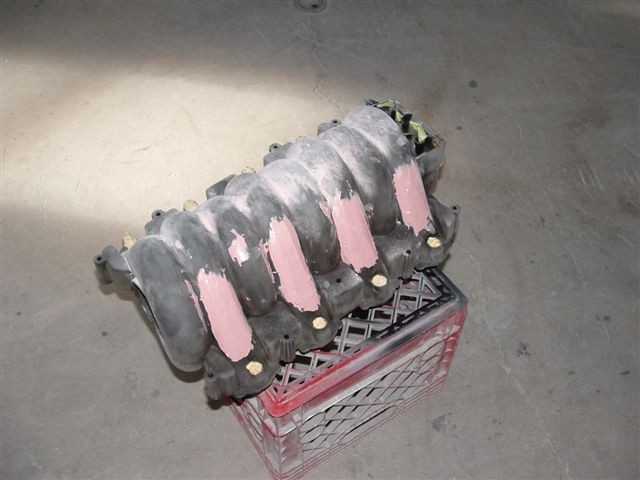
I dropped it off at the paint shop with instructions of my own for them to take a few pictures of it while undergoing the transformation. Here it is with the body filler applied. It’s the same stuff they use to fill the flexible bumper covers on cars. Apparently there are around three different levels of flexibility of the stuff… they used the stiffest.
Luckily they quoted me a cost of $300 to do this work and stuck with it. It sounds like a lot of money (and it is) but, I wanted it flawless since it’s the main point of focus when you open the decklid. The body man who I know to be very experienced and also a perfectionist, said it took him 5 hours, not two, to properly shape the filler to the contours of the runners. They had originally thought it would take about two hours. Here it is with the sanding underway.
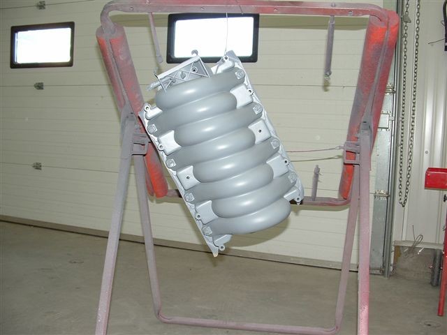
With it fully shaped, the next step was the application of an epoxy primer. Here you can really see how much cleaner the lines of the plenum are.
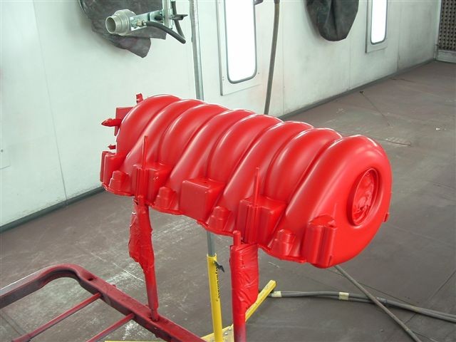
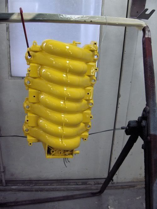
I had searched for just the right color when I saw a late model Mazda in “True Red”. The color code is A4A. Here’s the plenum with the flat looking basecoat sprayed on. Notice the air drier in the background… the body shop is a fully modernized water-borne paint facility.
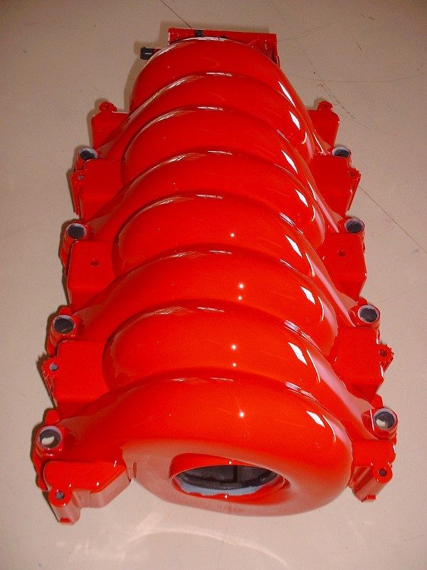
And finally, with the clear coat. This thing looks like a whole bunch of Rolling Stones lips all puckered up and ready for a big wet kiss… something the painter thought I would give him when he saw how happy I was at the way it turned out.
Thanks Pat, Charlie, and Joe. I figure whatever he lost on the plenum, he knows he'll be more than able to make up for it when it comes time to paint the whole car! There's no such thing as a free lunch.
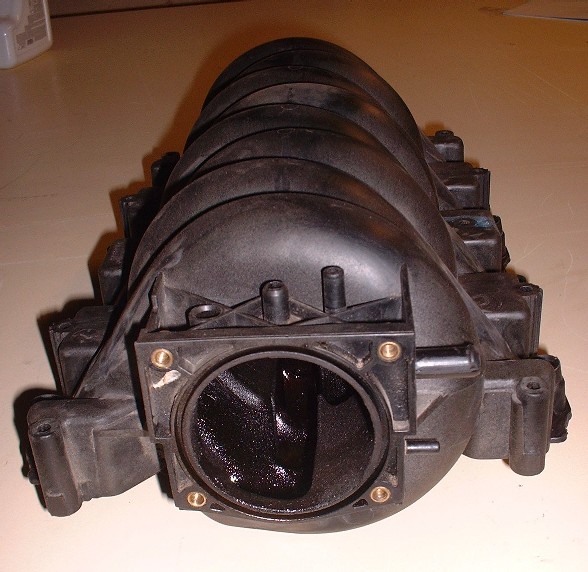
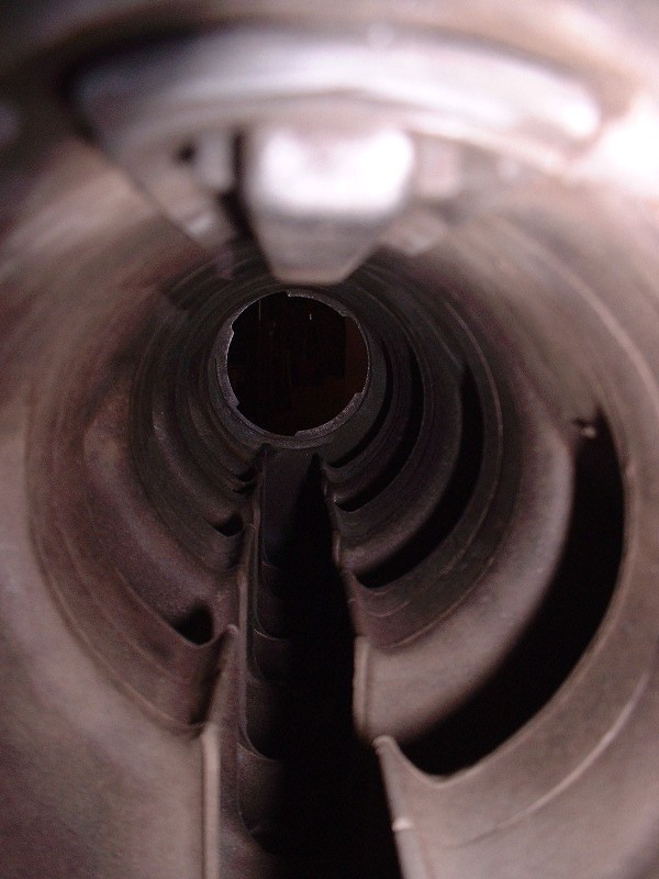
Anyways, with the plenum back in my hands, I did one final clean out of the innards to make absolutely sure there was no body filler dust or wads of masking tape hiding in there just waiting to get sucked into a cylinder on first crank. Here’s how much nicer the insides looked with all that carbon and those oil puddles now a thing of the past. The openings of each intake runner are at the bottom.
Before I could install the plenum on the block, I had to finish up the wiring to the starter and the knock sensor since they're in the valley underneath the plenum. I cleaned up the eyelets and replaced the corrugated plastic wire loom since it was fairly brittle from 15 years of soaking up the heat in that little cave.
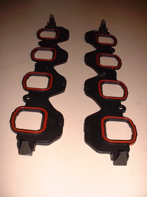
New intake runner seals were included in the FelPro Cylinder Head Seal Kit. They’re just an ABS-type plastic with neoprene-like injected seals around the base of each runner.
They clip onto the plenum at either end like so. Good thing I verified what each of the little moldings were on the plenum before I shaved it! Actually it probably wouldn’t have made much difference since the mounting bolts locate them anyway.
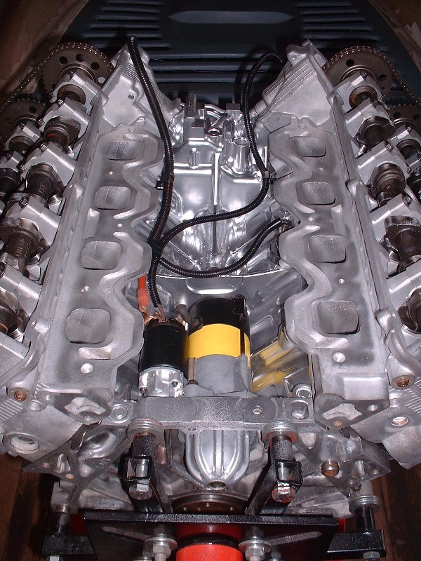
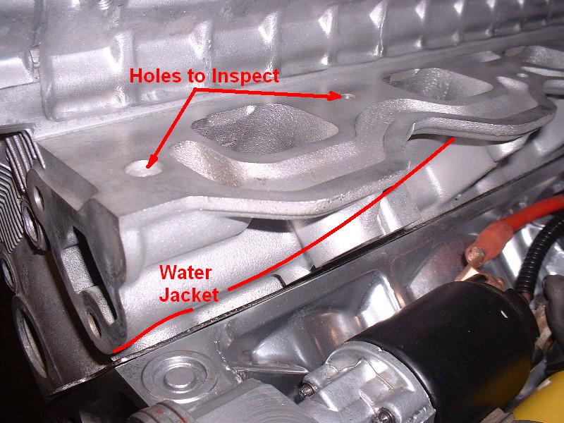
A quick inspection of the plenum mounting bolts revealed that the long ones had old thread sealant on them. This got me curious so I inspected the ten holes in the heads and found that none of them appeared to breach into the water jacket, but clearly GM didn’t want to take chances. In this picture you can see that the four bolt holes closest to the transmission could easily need thread sealant to prevent leaks. I added some RTV to the bolt threads just to be sure I wouldn’t have problems later.
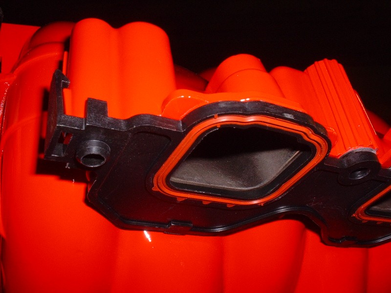
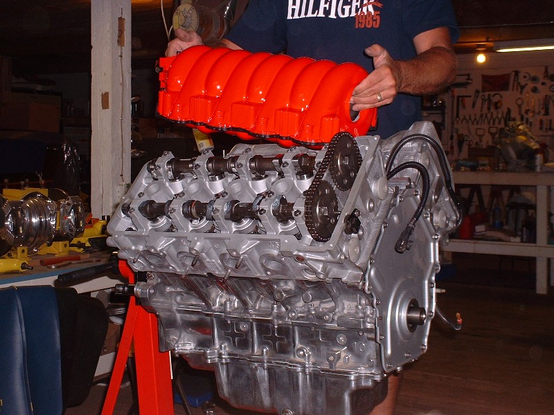
Ahhhh… finally time to install the lips… uhhh… I mean plenum. It just lowers straight down onto the intake port “shelf” of the two heads.
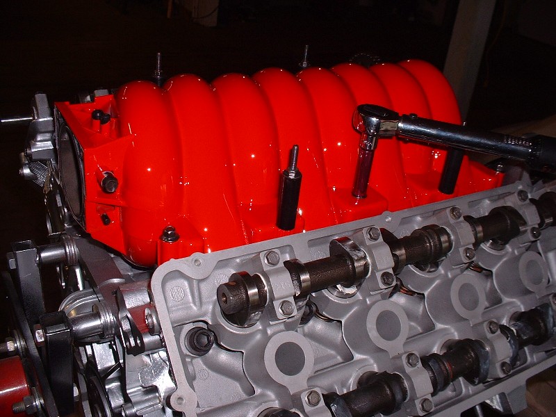
The plenum is held in place with six shorter bolts, and four longer studs that sandwich plastic stand-offs to the intake. The stand-offs are there to mount the beauty cover, but in my case, they'll only be needed to mount the new stainless fuel rail at the correct height. All the bolts get torqued to 89 in-lbs starting with the bolts closest to the middle and progressively working your way outboard.
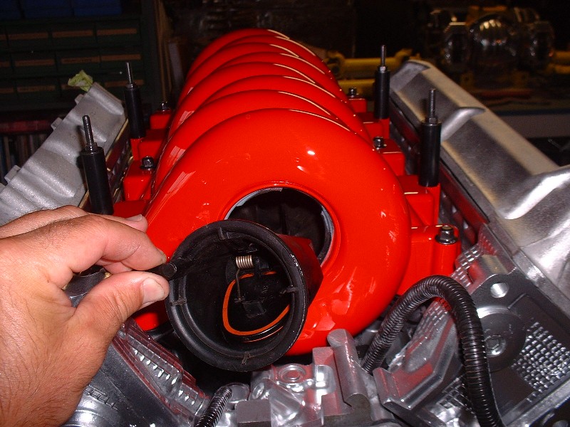
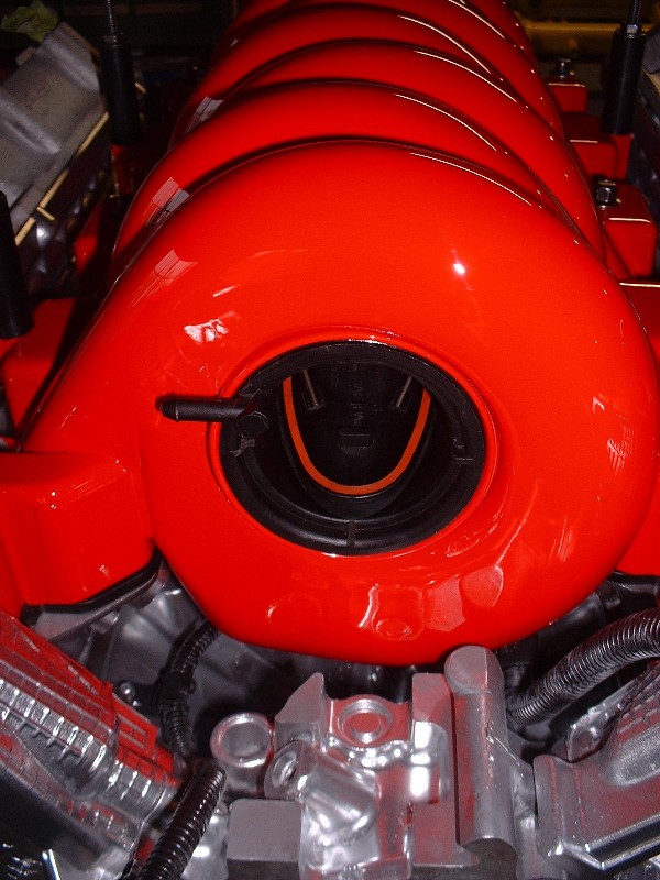
Here’s me installing the freshly cleaned backfire protection valve (at least that’s what I call it ). If you remove your vavle, lubricate the large O-ring before you reinstall it. The valve just gets stuck in the hole at about a 45 degree angle to engage a set of tabs into mating slots, and then rotated so that the valve is at the bottom and locked in place.
Here it is snug in it’s hole, hopefully never to be needed.
I knew the pokes were coming. I've been off the build thread radar lately since I've been doing transmission and suspension stuff for a change in pace, but I don't want to post stuff out of order in the thread. I did order a pair of CHRFab's polished double bump cam covers... still waiting on them though. It was tough shelling out $650 clams but I think I would have regretted spending any money or time trying make the stock covers look good.
The rules for the construction zone say you're not supposed to post fluff, but here goes anyways. I'm also doing a few renos to the inside of my car storage building. I store 85 classic & prestige cars for local people over the winter months... kinda like a grown-up candy store here in the winter. I drool a lot! 16,000 sq ft of cool cars.
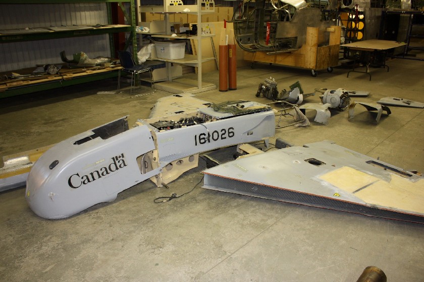
I also volunteer at the local military aviation museum (I know... blah blah blah...) but thought some of you might like to see what I'm rebuilding over there too. It's one of the first UAVs (unmanned aerial vehicles) that Canada bought for use in Afghanistan back in 2000 or so. They weren't that great, but they look neat! Now if I could only find a way to hook up that infrared camera turret to the 355 without drawing too much attention...
Intermission is over... stay tuned fo more F355 stuff soon.
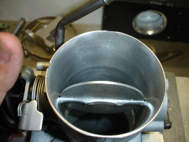
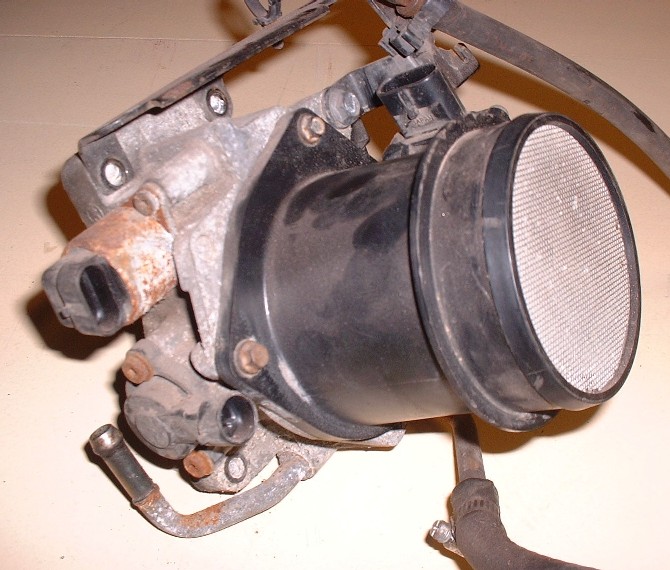
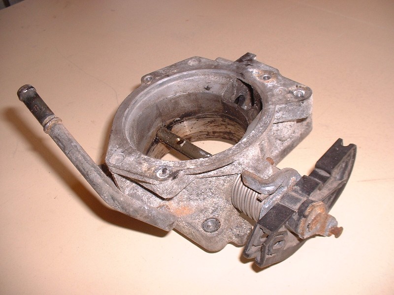
I finally managed to find some time to work on the Blooze-mobile over the past couple days. My objective was to get the throttle body taken apart, cleaned, polished, and rebuilt. I consider it a success story, but I’m getting ahead of myself. So for starters, Here’s a picture of what the TB/MAF looked like when I removed it from the intake manifold several months ago. Pretty rough looking, but I saw it as an easy challenge compared to what I had to do to the engine block to get it shiney.
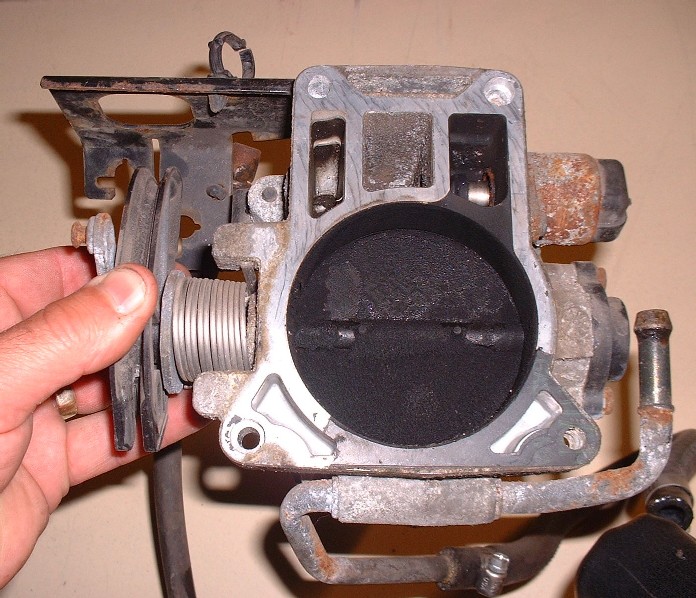
And here’s what lurked behind the throttle plate… there was enough carbon built-up to choke off an industrial incinerator in that thing. Clearly oil was getting into the combustion chambers and leaving a mess in the intake via the PCV and IAC port.
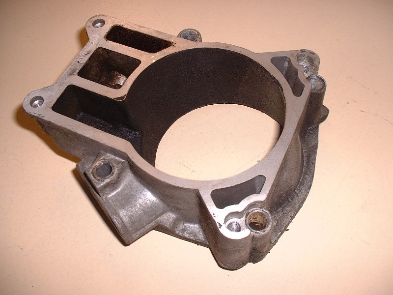
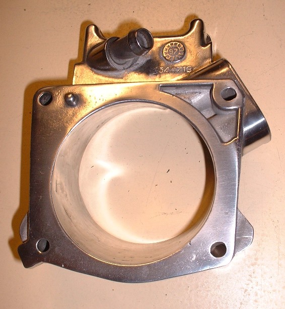
This is the other half of the TB which I call the TB adaptor since it bolts between the TB and the plenum. It was pretty crudded up with carbon too. Little did these Pigpens know that no matter how baked on their carbon or how corroded their exteriors were, they’d stand little chance of resisting the cleaning they were about to get.
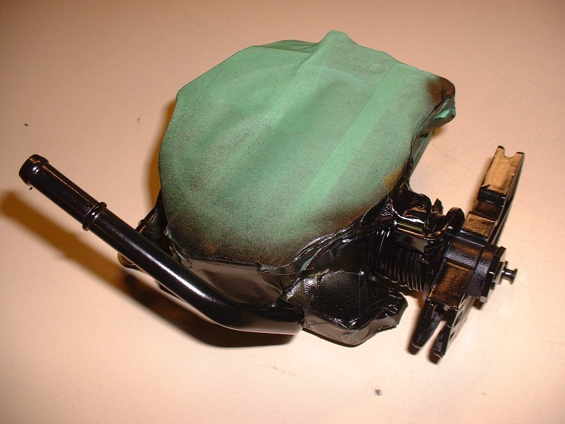
After stripping them down of all the sensitive doo-dads like IAC, TPS, throttle plate, and various seals, they were ready for the glass-beading booth. Here’s the TB ready for some deep cleaning.
Once they were bead-blasted, I spent about 6 hours sanding them smooth again (at least as smooth as I had the patience for!) and polishing them with various buffers. There’s lots of nooks and crannies on the TB so it’s impossible to get them all, even with a Dremel. But before I unveil the masterpiece, I first wrapped it up in masking tape and hit all the exposed steel with some primer and then a coat of semi-gloss black Tremclad.
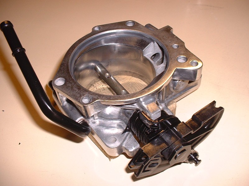
And now, the moment of truth… drum roll puh-leeeease… and draw the curtain! Ta-dah!
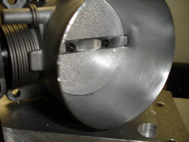
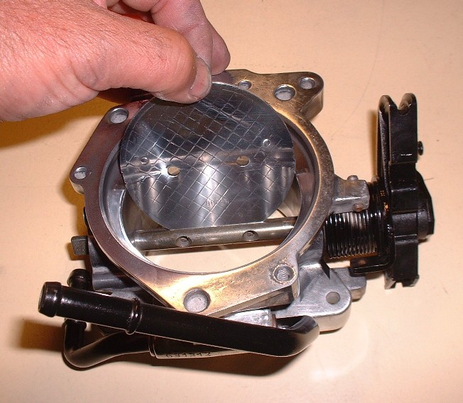
OK maybe a little too much drama, but at least it’s a lot better than it looked. With the dirty work done, the rebuilding phase could start. If you ever take one of these TB’s apart and get stuck not remembering which way the throttle plate goes back in, it’s easy. Just make sure the numbers stamped into it are facing upright and toward the MAF.
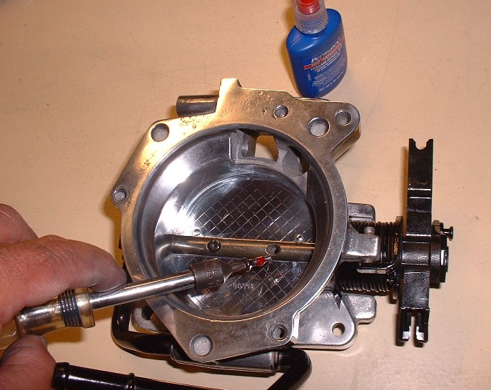
Once in place, the throttle plate gets secured by two tiny screws that are Locktited into place… they’re the last thing you want to have vibrate loose because they’ll only head in one direction if they ever come out!
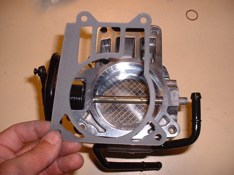
A new gasket came with the master rebuild kit so I used it… no sealant required just apply it dry.
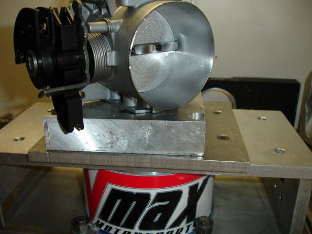
Then I installed the two halves together and torqued them as per specs. Here’s where I got ahead of myself (again) and caused some unnecessary work. Before you attach the two halves together, you’re supposed to attach the throttle body adapter to the intake plenum and then the throttle body to the adapter. The reason is quite simple: the throttle body covers up the screws that are used to attach the adapter to the plenum. I forgot about this little detail so I kept building up both halves of the TB as shown in the next few pictures. Just don’t follow this sequence if you’re doing this yourself. (Come to think of it, this’ll teach anybody who just looks at the pictures a little lesson!).
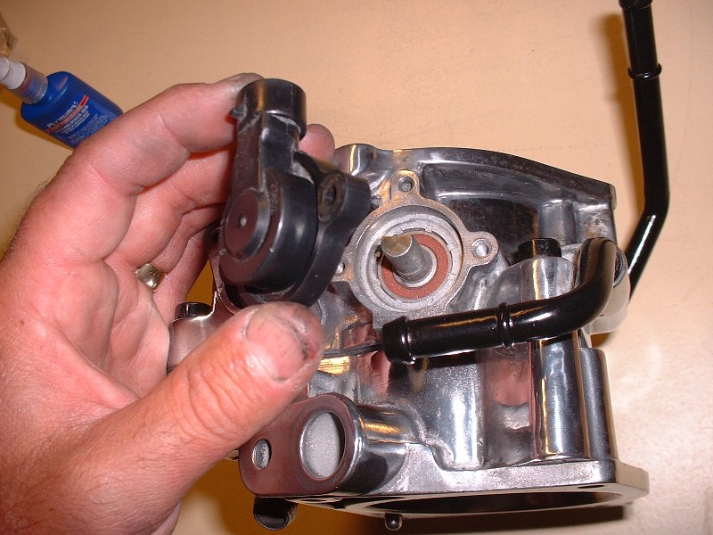
Next was the throttle position sensor (TPS). You can’t go wrong with this one… the throttle shaft is D shaped so the sensor will only go on in one orientation. It’s held on with two little screws.
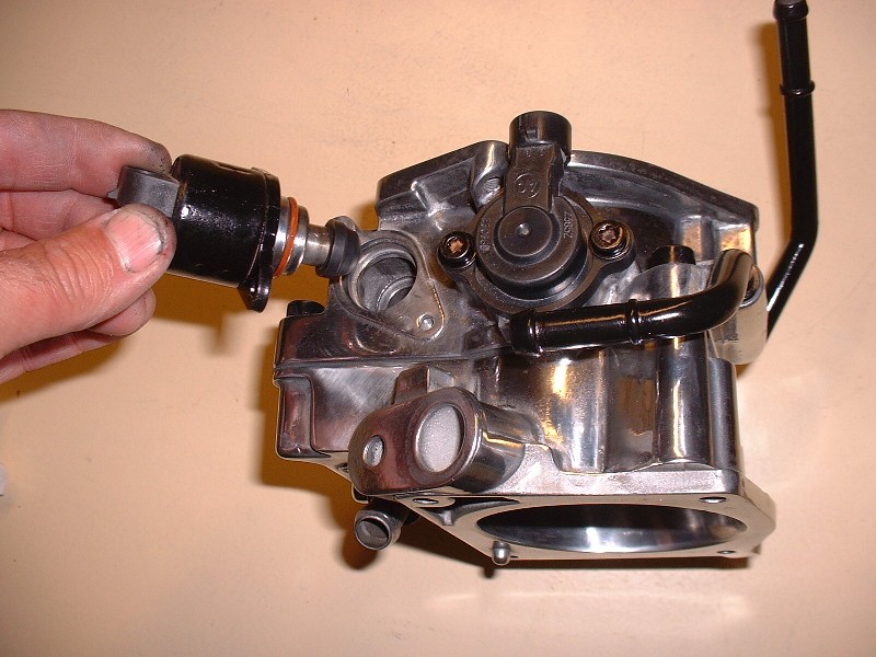
Then the idle air control (IAC) valve was installed. There’s no special instructions for the Northstar IAC unlike the Fiero one where you have to retract the plunger etc. Just put it in the hole and tighten the two little screws.
So here’s where I had to undo the part about installing the two halves together. In order to be able to install the TB adapter to the plenum, it has to be done before the TB is mounted onto it. Here you’ll see the new O-ring that also came with the master rebuild kit. It gets installed in the plastic plenum opening.
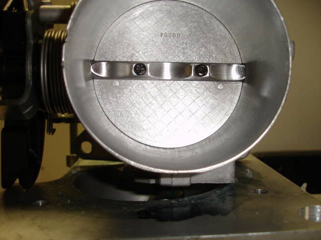
And finally the TB gets screwed onto the adapter (again). I used Locktite on all the screws to keep them from ever backing out on their own. And causing air leaks.
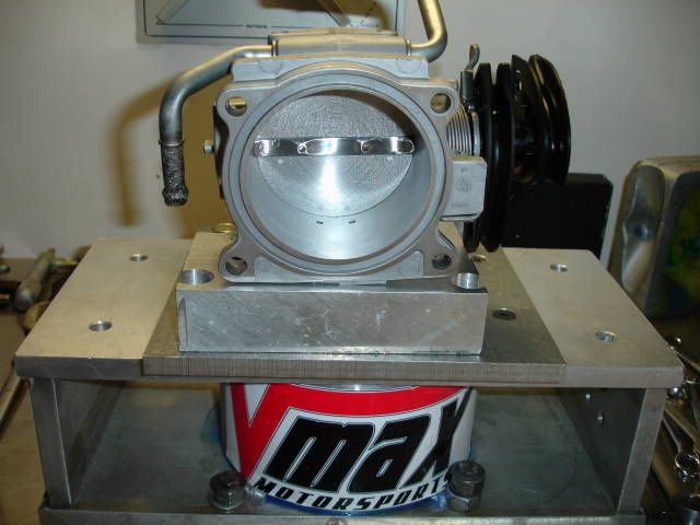
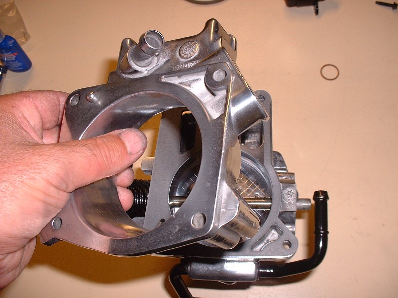
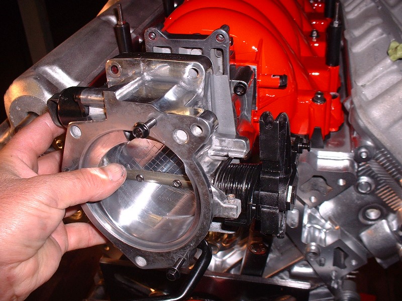
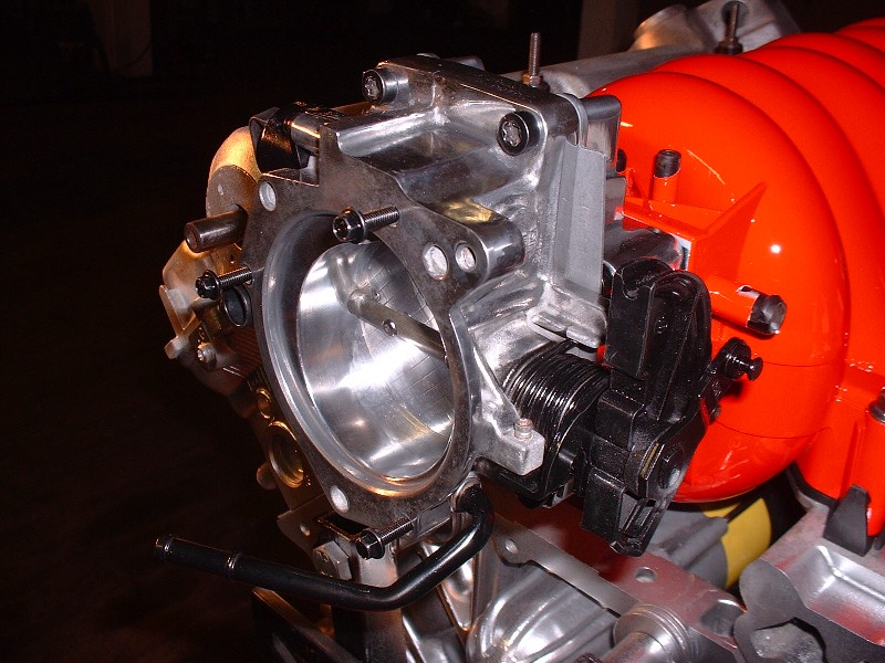
Here’s what the thing looks like once it’s installed.
Next up… I got a surprise in the mail yesterday… but all I’ll say for now is that they’re nice and shiney!
Originally posted by Bloozberry:Next up… I got a surprise in the mail yesterday… but all I’ll say for now is that they’re nice and shiney!
Hmmm, I wonder what that might be...? Hint, Curly recently had some pictures posted of these and yes, they are very shiny! Of course you were nice enough to let the cat out of the bag a while ago...
quote
Originally posted by Bloozberry:I did order a pair of CHRFab's polished double bump cam covers... still waiting on them though. It was tough shelling out $650 clams but I think I would have regretted spending any money or time trying make the stock covers look good.
Very nice job cleaning up the TB! (I spent a lot of dough just to avoid having to do that... )
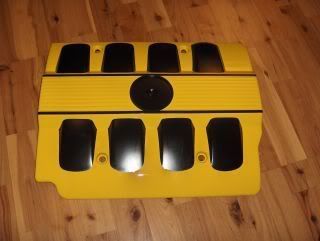
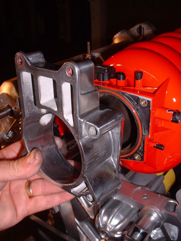
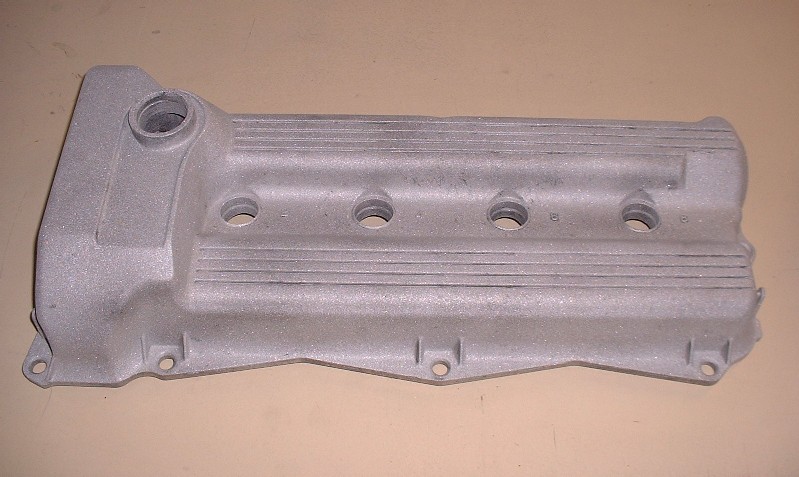
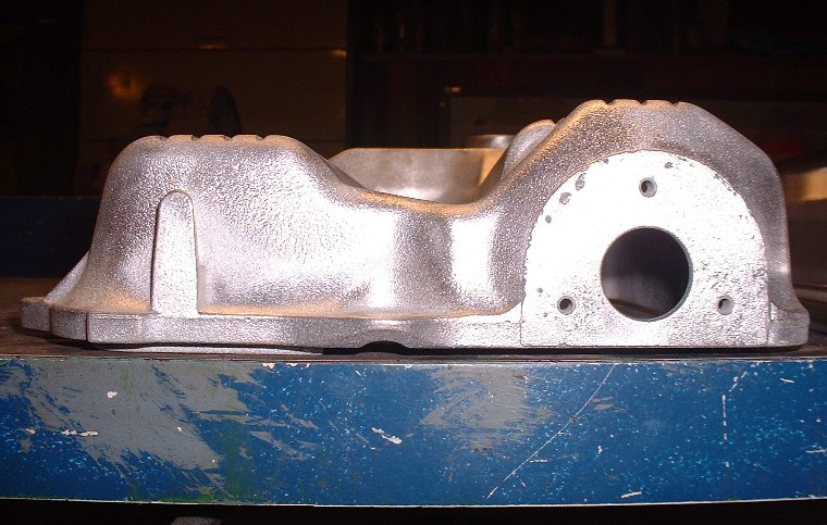
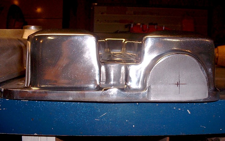
In case anyone reading this has had their heads stuck in the sand, the '93-'97 Northstar (and perhaps later years too), came with only one nice looking valve cover... the one that's seen front and foremost when you open the hood of a Caddy. This is what the pretty one looks like once it's sandblasted and ready for paint:
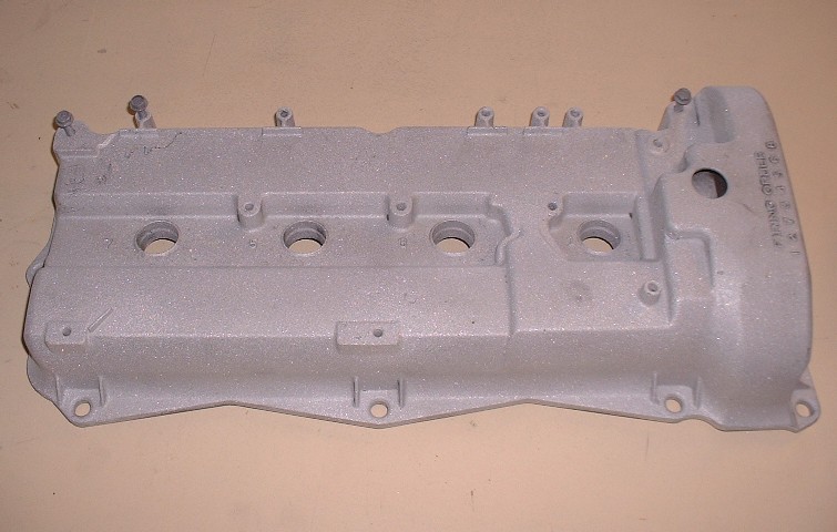
The problem with installing a Northstar in a Fiero engine bay is that the pretty valve cover is up against the back of the seats, exposing the ugly sister to show all her warts in plain view when the decklid is open.
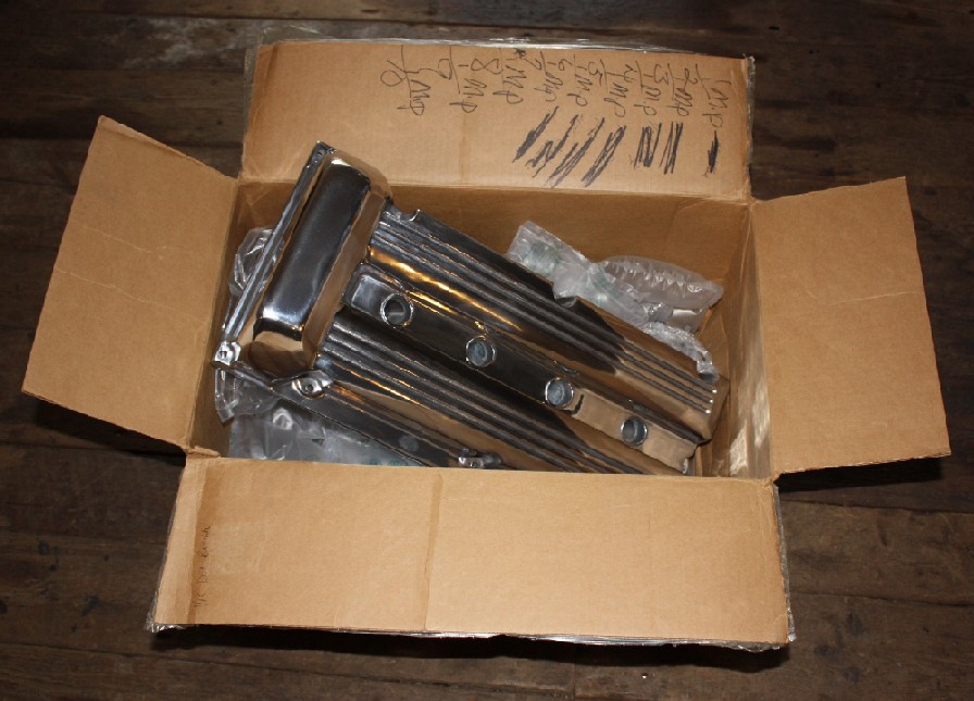
I seriously considered spending upwards of a hundred hours shaving warts, sanding the pebble finish, and polishing these two fraternal twins into something befitting of a Ferrari's engine bay, but I just couldn't picture any amount of plastic surgery that would cut the biscuit. So, I broke down and phoned CHRFab three weeks ago. A couple days ago I got a parcel-delivery notice in the mailbox. I like parcels (even if this one came with an additional invoice that I owed $107 in federal and provincial taxes before the post office would hand it over). I was surprised at how heavy the box was... secretly I was hoping that they accidentally sent me two pairs of valve covers, but that was not to be. I was happy when I opened the box nonetheless.
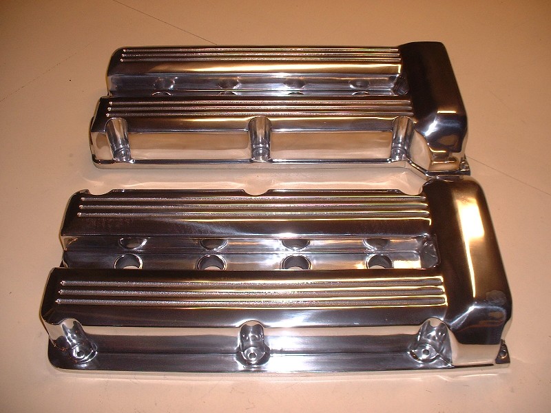
These are things of beauty... of course they should be for the price! They're fairly substantial castings too. I know others have posted pictures of them before, but here's a few more for the record. What you don't see because of the glare, is my smiley face reflected in the polished aluminum. And if fingers could smile, all ten of mine would be flashing their pearly whites too, happy that I spared them the labor.
As beautiful as they are, in my next post, I'll cover a few things about them that left me wanting a little more given the premium price tag.
(Edit: PS... Thanks for pointing out that extra gasket material on the TB there Jefrysuko! It's history!)
[This message has been edited by Bloozberry (edited 09-10-2010).]
I am surprised I am not blocked from your thread for being the party pooper. I was just letting you know that I actually do read it. (but mostly I look at the pictures! )
Gorgeous!, they look like they will go very well with the rest of the parts you have meticulously polished up.
So like I said, here are my observations on the cam covers. To be fair, I should note that I decided to accept them the way they are and I haven’t contacted CHRFab about any of these issues. The reason I’m posting this info is so that anybody else ordering a set of these may know what work may lie ahead of them, or to be sure they address these issues directly before ordering.
My initial awe at these masterpieces was tempered somewhat after examining them more closely. As motoracer838 pointed out, the first thing is that there are no ports for crankcase venting nor oil filling, but this was not a surprise since CHRFab states on their website that vents aren’t drilled so you can configure the covers as you like. For oil filling, they suggest either ponying up another $50 at time of order and they’ll weld an aluminum oil fill bung anywhere you like. If that doesn’t suit your fancy, then they suggest filling the engine using any of the four removable plastic plugs on the fronts of the heads. To keep the appearance as clean as possible, that’s what I think I’ll do.
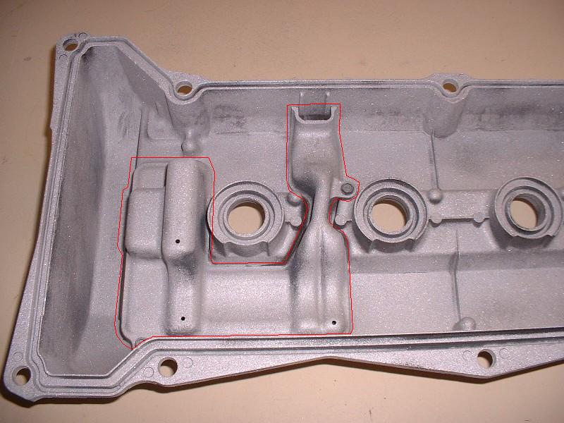
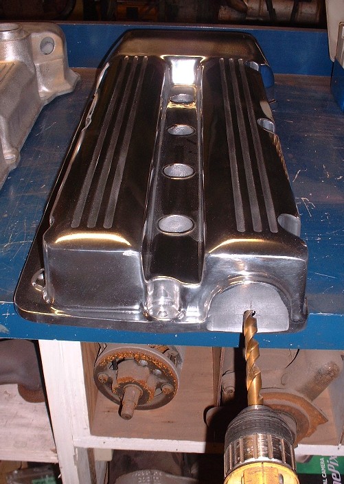
So problem #1: Something that took me a little by surprise was that the insides of the new cam covers don’t have provisions for screwing the PCV baffles into place. Here’s what I’m talking about on the OEM covers:
I’ll have to do a bit of research but I seem to remember having read in an older thread where oil ingestion into the intake can be caused by improper sealing of the oil baffles under the stock cam covers. Clearly if sealing is an issue, then not having the baffles at all must present a real problem.
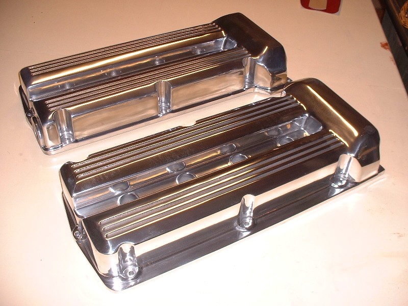
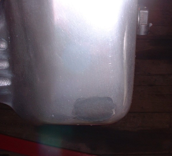
Problem #2 was that there is a dark spot on the rear cam cover… the cover that’s seen in a Fiero. It appears as though there must’ve been a casting void that was later filled by welding, and then an attempt to polish it out. The filling was well done, but there’s an undeniable blemish. You can see the area I'm talking about in the last two pictures of my last post in the bottom valve cover at the bottom right corner on the sprocket hump. Here's a close up look:
Problem #3 was that there were polisher marks in the finish of both cam covers… not from incomplete buffing, but from accidental slips with the buffing wheel. If you’re not familiar with polishing techniques, then the issue is that portions of them were polished in one direction and other portions were polished at 90* to the first part. This isn’t necessarily a no-no as long as the different portions aren’t in the same plane. The trouble happens when you slip with the buffer and contact an area that’s already been polished in one direction, with the buffing wheel at 90* to that part. It leaves buffing marks clear as day across the previously polished area. Although I was unable to take pictures of this effectively, I had to spend at least an hour re-buffing both cam covers because their buffer accidentally touched areas that had already been buffed in a different direction. For anyone without the tools or skills to rebuff them, this would have been cause of great disappointment.
On a related note, the spark plug holes in the covers were full of buffing compound. To me, this is just sloppy. I did not expect to have to clean the cam covers.
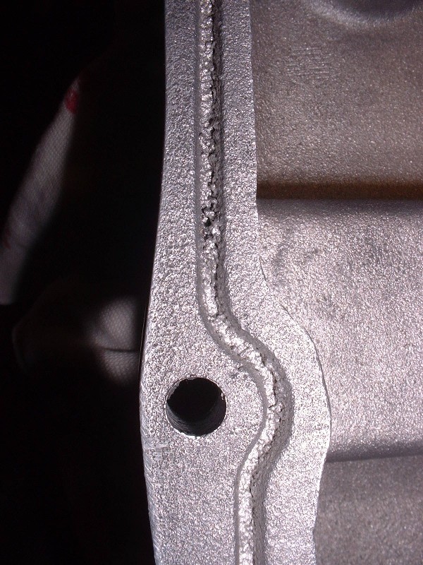
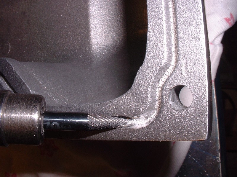
Problem #4 involved more casting issues. When I turned the cam covers upside down, I noticed that the groove for the cam cover gasket was cast and not machined into the parent material. This isn’t necessarily a problem in itself, but again, the casting wasn’t perfect. There was a fair bit of very granular casting flash in the bottoms of the gasket grooves which would have prevented me from installing the gaskets properly and would have caused leaks. Here’s a picture of what I’m talking about:
To correct this I had to take a die grinder with a special bit and carve out the excess aluminum from the grooves. Once again, for the average Joe without the right tools, this may have presented itself as a major hurdle. It was certainly a disappointment regardless of experience and skill.
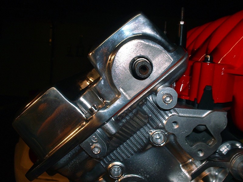
Problem #5. On the Northstar engine one of the intake cams protrudes through the cam cover so that a small pulley can be attached to drive the water pump. In addition, there are supposed to be three tapped holes to be able to secure the seal that prevents oil from leaking around the cam where it sticks out of the cover. Neither the camshaft hole nor the seal mounting holes were bored. I returned to the website where I bought the covers and could not find where it was stated that these had to be machined by the buyer. Have a look at the stock cover:
And the cover as delivered (note that the marks for determing the location of the hole were made by me):
One final problem was that the cam cover, even once modified for the water pump drive shaft, would not fit on the engine. The covers are significantly heavier castings than the stock covers and the extra thickness around one of the cover’s mounting holes simply would not clear one of the camshaft bearing caps. This meant that I had to shave some material off the inside of the cam cover to get the necessary clearance. Not much… but enough that it could drive you crazy after all the other little issues to deal with.
Next post I’ll show you how I measured and made the holes in the right spots for the water pump drive shaft and oil seal.
The known problems are bad enough, but I think I'd be calling Alan about the other issues, that's wayyyy too much to expect the coustomer to take care of given what the things cost to start with!!!
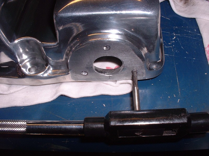
As I mentioned in my last post, the front cam cover needs to have a hole drilled through it to accommodate the intake cam on that side, which sticks out and serves as the water pump drive. My new CHRFab cam cover didn’t have the necessary hole so here’s how I went about getting it in the right place. It’s important for it to be accurate because the oil seal must be centered on the shaft or else it will leak.
The first step was to measure the location of the center of the hole on the OEM cam cover and transfer it onto the new cam cover as accurately as possible. It’s not rocket science, but there’s a monkey wrench thrown in for good measure. The OEM cover doesn’t sit flat on the workbench because of a gasket flange that protrudes below the bottom, part way around. So it wobbles as you try to measure the height of the hole. Anyways, it’s not super critical at this stage as you’ll soon see, so I drilled a pilot hole once I was satisfied.
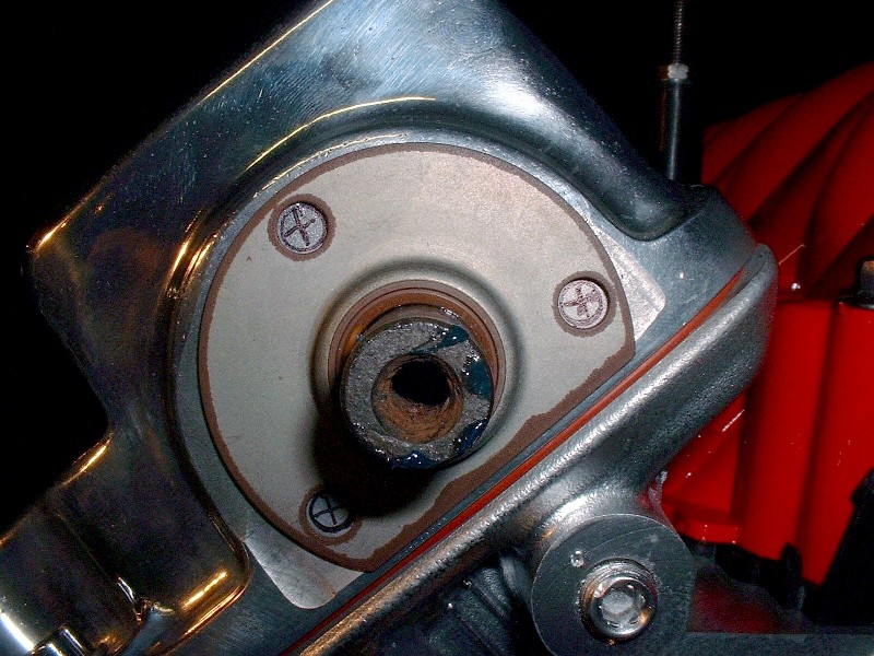
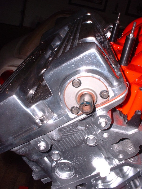
Once the pilot hole was drilled, I worked my way up to a ½” bit and then ground the hole to about 5/8” using a die grinder. I then installed the neoprene gasket, test fitted the cam cover and torqued the cam cover bolts to spec (89 in-lb). You need the gasket since it compresses to about 1/16” thick. This showed me that my original hole was off center by about 1/8” height-wise but at least I could now measure exactly where the hole had to be. To do this, I left the cam cover on and slid a large washer with a ½” ID and 1” OD onto the shaft and traced the outline onto the cover. Once the cover was removed again, I was able to grind the hole to 7/8” diameter (same as OEM), concentric to the correct center. Here’s what it looked like, torqued down, after getting the hole in the right location:
The next step is to locate the three oil seal mounting holes in the correct location so that the seal is perfectly centered on the shaft. The easiest way to do that is to install the seal on the shaft and mark the location of the holes:
Remove the cam cover again and then drill and tap them to about ½” deep. Drill size: 1/8” diameter; tap size: M4 x 0.7. Even at that depth, the holes don’t penetrate through the material of the cover so no sealant is required, however thread locker is used on the screws.
Here’s the final installation. Like I said, it’s not rocket science, but getting that seal on so it’s perfectly centered on the shaft is important.
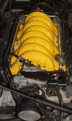
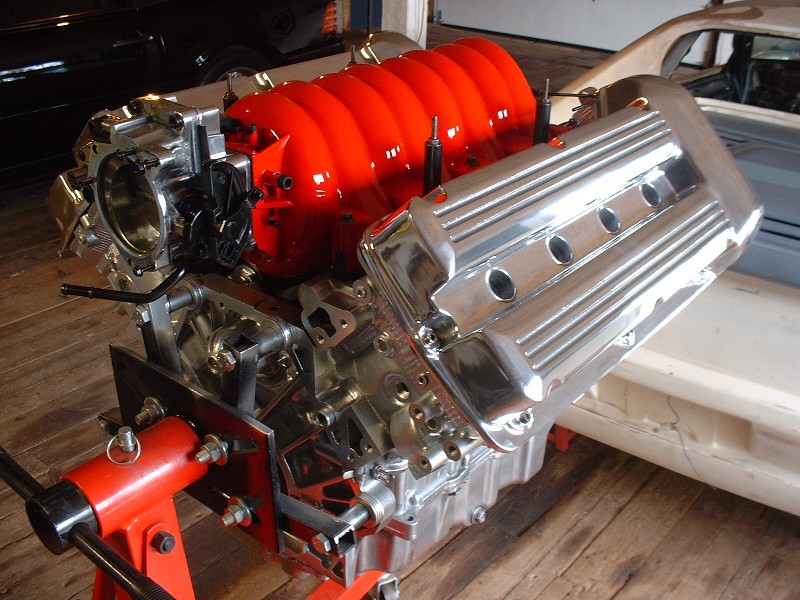
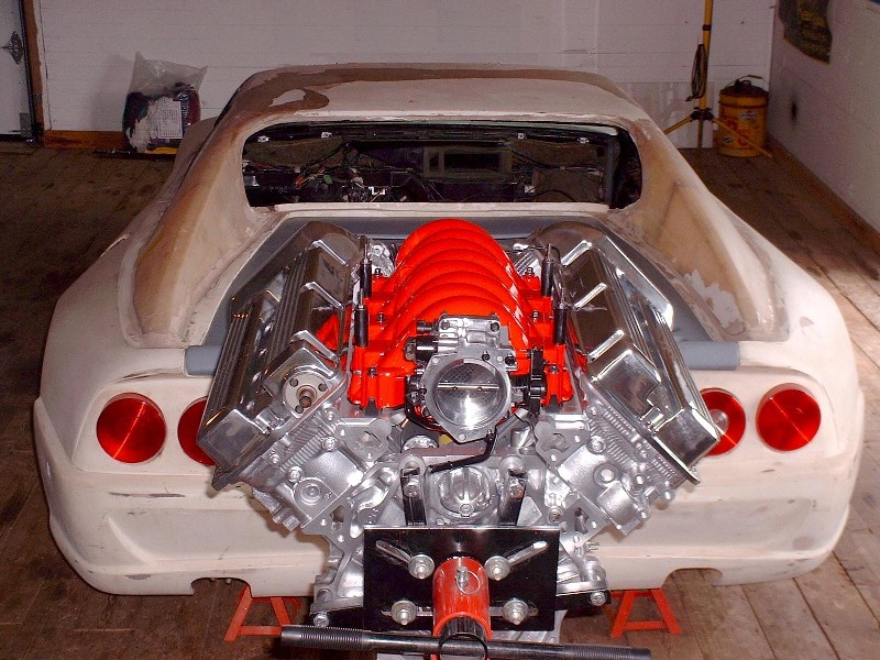
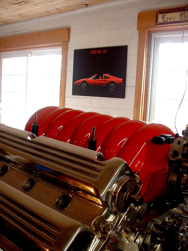
Finally, here are a couple shots of the covers installed on my engine. They certainly dress up the engine enough to look the part! Hopefully it’ll perform as nice as it looks.
Too bad it won't be installed longitudinally like this... it would look cool that way.
While I was taking a few photos, my 328 poster cropped up on the wall in the background, so I couldn’t help underscoring it with the top of the engine… too bad it’s not an F355.
At last I only have a few “accessories” to clean up and install before I finally get to business other than the engine. I still have to order up a stainless fuel rail, and sort out some PCV venting, clean, modify and install the pulley system up front, install the oil filter mount and the water pump/log. I’ll start with these last two, first.
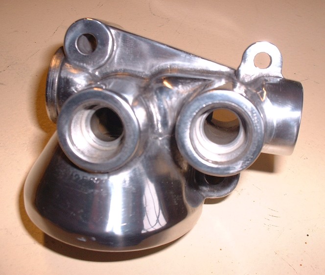
Depending whether your Northstar donor car originally had the towing package or not, your engine either has an oil filter mount with integral oil cooler ports or not. Of the two engines I bought one had the provisions for the cooler and the other didn’t. Since I’ll be running an unconventional radiator set-up, I decided to use the oil filter mount with the cooler ports to give me additional cooling capacity. I cleaned it up and installed it, but it just looked out of place and was screaming “Polish me!”
So off it came and two hours later it was ready to be installed again.
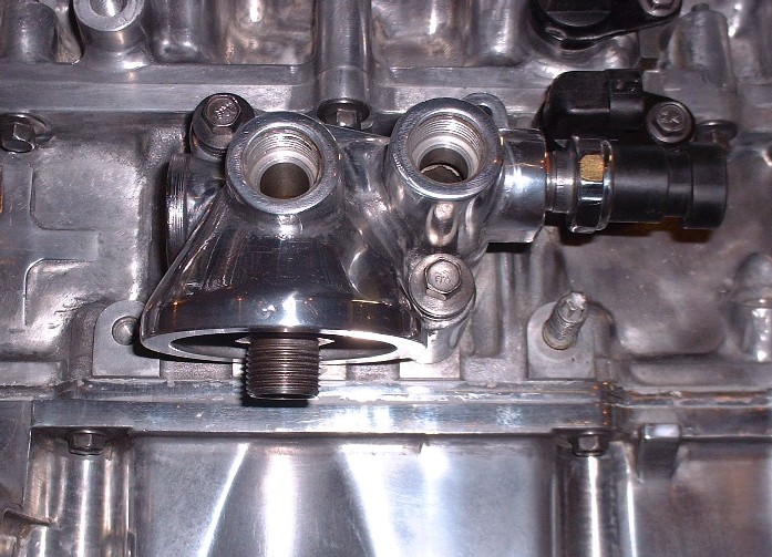
I got two new o-rings in my rebuild kit so I stuck them on before tightening the mounting bolts to 18 lbft. The oil pressure sender also gets installed into yet another port on the filter mount. It’s a pipe fitting thread so don’t forget to use some RTV.
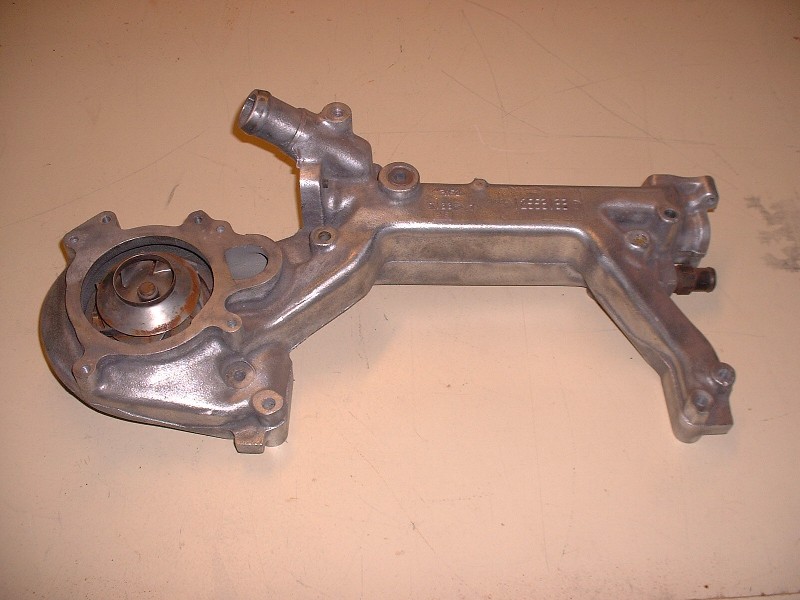
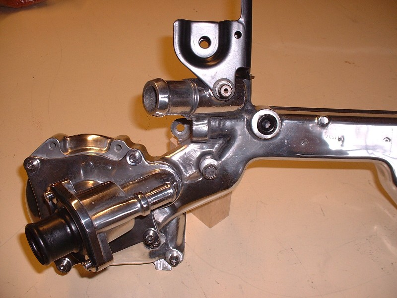
Next came a task I was not looking forward to. Polishing the water pump/log. For those who aren’t familiar with the N* configuration, the water pump is pressed into a huge aluminum water manifold that bridges the two cylinder banks at the back of the engine. It’s so long that many people refer to it as the water log. Here’s what it looks like off the engine.
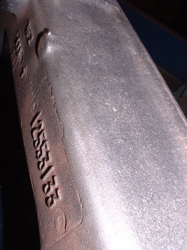
Up close you can see that it’s a rather rough sand casting with lots of raised, mismatched seams, manufacturing stamps and cast-in time, date, and part number stamps. Luckily not a lot of it is seen, but enough that if I didn’t polish it, it would look like I got lazy.
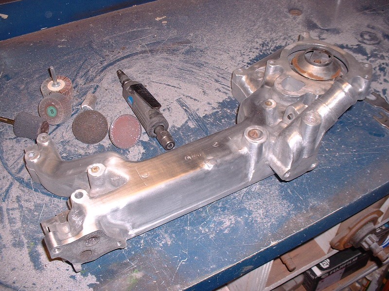
Today I started the polishing process by smoothing the water log out as much as possible. To accomplish this I broke out a handful of rotary sanding disks, flapper wheels, and grinding stones. It’s a messy job requiring safety glasses and a mask because the aluminum dust will end up in every one of your bodily orifices if they’re not covered… (yet another reason not to use a grinding wheel in the buff!) J At the stage shown in this picture I’ve used mostly a 3” and a 1” diameter 60 grit flapper wheel to get the pebble finish smooth and to remove the casting lines. Next up will be a special scrubby-type material buffing wheel to minimize the sanding marks, and then hand sanding… ugh.
That Nylon intake looks really nice painted red, I didn't think it could be painted. You have been making a lot of progress on the engine, it's looking really good with all that elbow grease. I added to my favourites .
Thanks Rourke, Doublec4, and Motorracer... I'm addicted to positive feedback! For Icelander, there's no way in hell I would have started polishing that log if it had to be replaced along with the water pump! I can just see the look on some rebuilder's face when he got my core in for remanufacturing. I think they would have mounted it on a plaque and made it the employee of the month award or something. I'm half tempted to mount it on a plaque in memory of my long lost fingerprints! Thanks for chiming in there Charlie too.
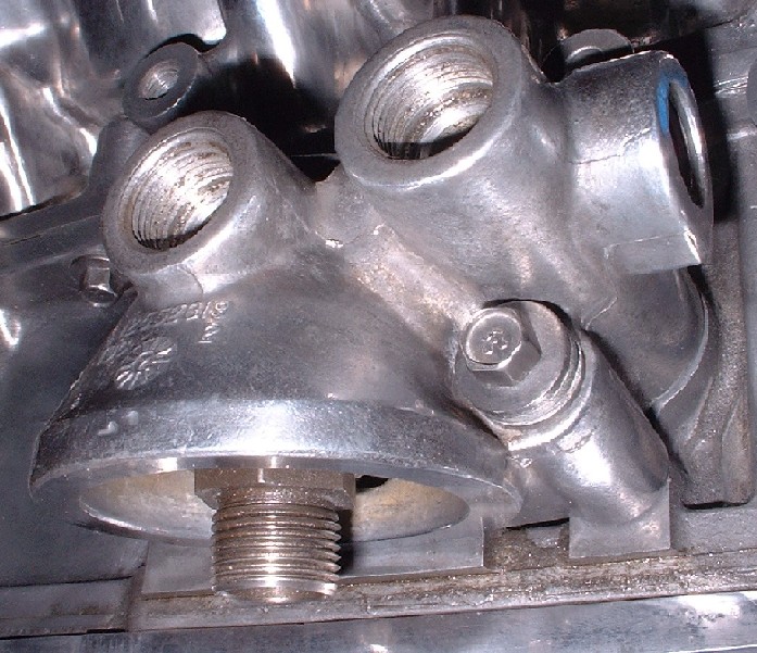
On a side note, I got diverted from polishing the log a bit when I torqued the oil filter mount onto the side of the block. The specs say it goes on with 18 lbft but as I was tightening them, I heard two snaps! Both bolts pulled the threads right out of the block. I'm still messing around with helicoils because I accidentally drilled and tapped one hole a little crooked, so the filter mount won't seat properly before the bolts bind up. So far, drilling larger holes in the filter mount hasn't corrected the misalignment enough to solve the problem. Arghhh!
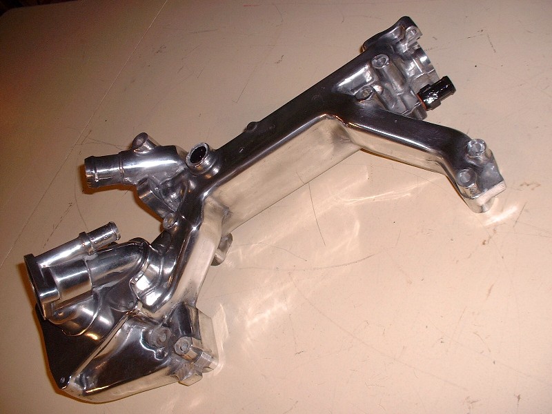
Well I finally managed to finish sanding and buffing the water log. There were a lot tricky spots on it that needed special attention and special tools. I’ve found that to get into the ½” concave radii, the best tool is a tightly wound roll of sandpaper about a ½ ” in diameter and 3” long that’s made especially for porting cylinder heads and such. You screw it on a special needle-like mandrel that fits in your ¼” shank die grinder. As the outer layers are worn off, the inner layers are exposed, so one little roll lasts pretty long. Works fast and does an excellent job in those tough-to-get-at corners. In all, I spent 12.5 hours from start to finish on this piece, and I'll be the first to admit it’s not perfect, but then again if you've ever looked into the bay of a N* Fiero, there isn't much of it that's going to be seen. So before anyone asks the obvious question, my compulsive obsessiveness made me do it.
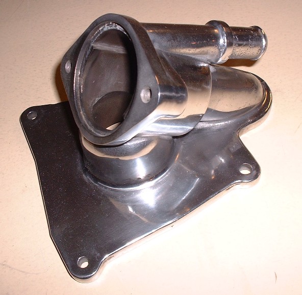
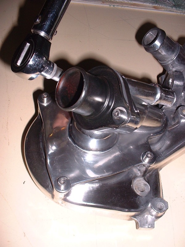
Here’s a close-up of the combination thermostat housing / water pump inlet. I personally don’t know how anybody makes any money polishing metal for others.
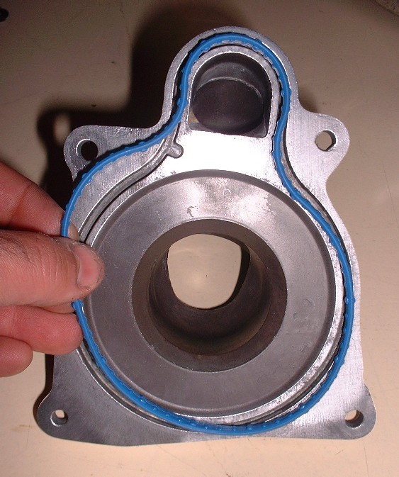
To install it on the water log, you need a specially shaped neoprene-like seal. Mine came with the master rebuild kit, and it’s a good thing, since the old seal needed to be removed from the groove to clean up a little oxidation and antifreeze deposits. It crumbled when I tried to take it out.
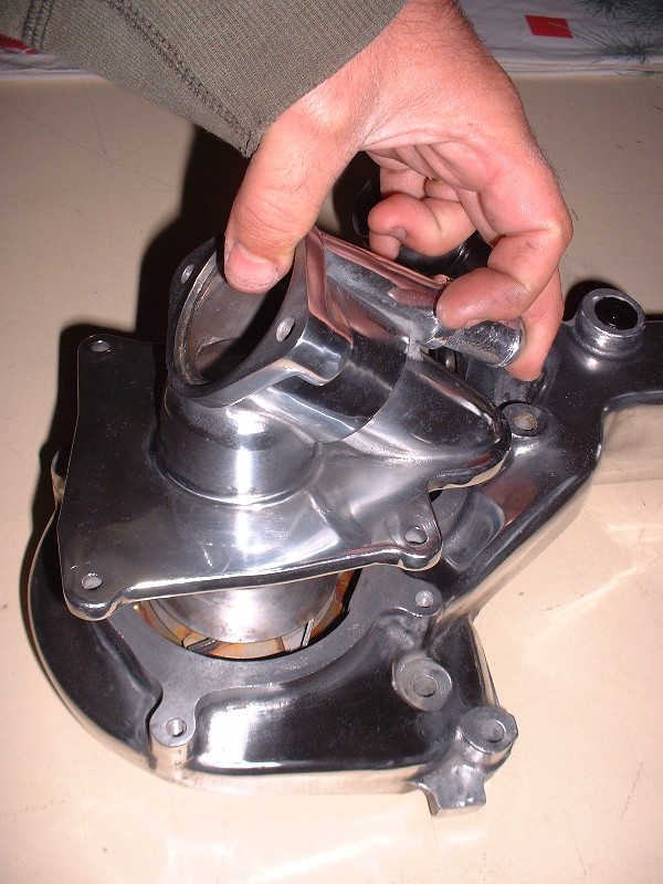
Once the new seal is in place, the housing is installed with just four 6mm bolts. They get torqued to 89 lb-in and don’t need any sealer on the threads since they don’t break into the water jacket of the pump. For the water log and it’s accessories, I decided to buy all new stainless steel socket head bolts. I take the belt sander to the fine ridges on the OD of the bolt head to get rid of them and then polish them on the buffing wheel. They look ten times better than the old steel hex head bolts and they’ll stay that way for eternity too! The nice thing about stainless is that it should minimze the galvanic interaction between the steel and the aluminum.
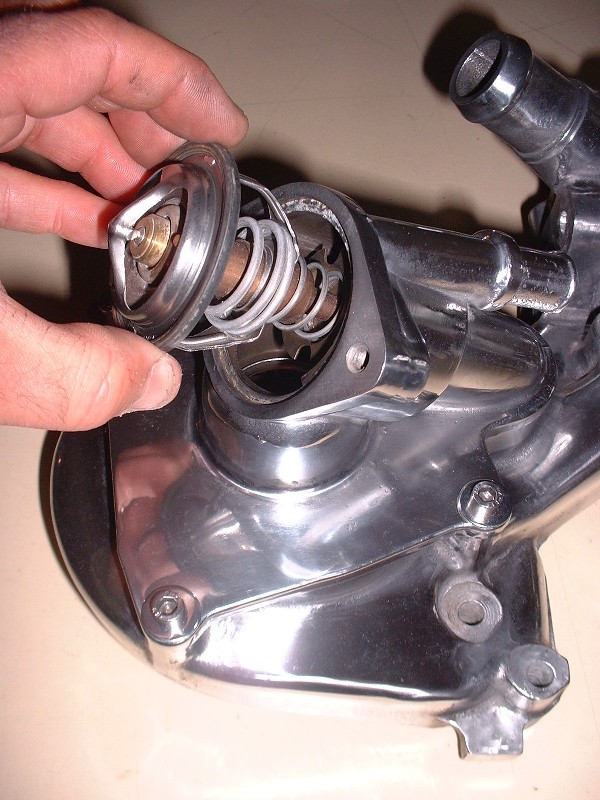
Next up is the thermostat itself. Interestingly, this T-stat has a small vent hole drilled though the shroud already… almost like they knew it would be a challenge to bleed the air out of this monster.
Finally, the thermostat neck gets bolted on with a couple 6mm bolts torqued to 89 lb-in as well. No additional seal or gasket is required because the thermostat comes with a rubber o-ring around its outside edge.
Here’s the pump end of the water log all built up. The eagle-eyed among you will notice that I’ve installed the dog bone mount. I'm hoping to be able to use it. The one bolt that you can see for the mount is actually a hollow bolt that taps into the water jacket so it needs RTV on the threads. The coolant hose coming from the throttle body heater connects up to that bolt.