Originally posted by FieroWannaBe: The reason the Ford GT and Ferrari F360 have less than unity camber change characteristics is becuase in straight line acceleration and deceleration, the subsequent suspension deflection will cause the tire contact patch to deform and shrink from wheel camber change.
Ahh yes... sometimes I can't see the forest for the damn trees! I was concentrating on roll and overlooked considering bump at this stage. I can see how a 1:1 camber change vs roll angle would adversely affect straight-line acceleration due to squat. For lack of a better standard, I'll try to relocate the upper control arm to approximate the 0.7:1 used by the examples you gave. Thanks!
Another consideration, for which you are already qualifying:
Keeping the lower rear attachments keeps the factory amount of roll steer, which is toe-in on compression, inducing understeer. And, the relative amount of camber change in roll from front to rear will affect cornering balance; as available grip at each end is influenced. A little more camber gain at the rear vs. the front will give the rear more available grip than the front, keeping the understeer balance.
Thanks FieroWannaBe. One of the main reasons I wanted to keep the rest of the suspension points relatively stock was to keep myself from having to redesign any more than needed. As you mentioned, the shorter forward lateral link provides the correct toe change direction on the outside wheel in a turn to help counteract oversteer.
OK, so taking FieroWannaBe's advice I set the camber-to-roll ratio at 0.7:1 meaning that for every degree of body roll, the wheel camber only changes 0.7 degrees. I did that by tilting the body to the maximum 6.0 degrees of body roll I want, and then setting the outer (LH) wheel to -6.0 deg x 70% = -4.2 degrees of camber relative to the body (or equivalently 6.0 - 4.2 = 1.8 degrees tilted outwards at the top from vertical). I left the inboard (RH) wheel vertical (or at +6.0 degrees camber) since most of the weight will be off that wheel anyways, and having it flat on the ground will help marginally without impacting straight line acceleration). Then, once again I arbitrarily used the lower of the two strut-to-knuckle holes on the knuckle for the outboard upper control arm pivot point, and I set about finding the optimum length and location of the inboard upper control arm pivot.
To do that, I had to satisfy two criteria at once. The first was to make sure that at 6 degrees of roll the control arms were the same length and the pivot location was same location relative to the frame side to side even though the wheels were at very different locations relative to the body. The second criteria was that the two wheels had to return to zero camber once I rolled the body back to level. Luckily I figured out a repeatable multi-step approach to accomplish this using stick figures.
Unfortunately the result of my first attempt at a 0.7:1 ratio had a catastrophic effect on the roll center movement. The instant center for the inboard wheel went to infinity as the upper and lower control arms became parallel to each other. That sent the roll center flying off the page. I can post the drawings if anyone wants to see the results, but if not I'll just move onto what I came up with instead.
After studying what went wrong, I could see that I needed to get a steeper angle on the upper control arm to prevent it from going parallel with the lower control arm at any point in the range of movement. The simple solution was to move the upper control arm's outboard pivot point from the lower hole in the knuckle to the upper hole and try it again. After a few minutes of recalculating the optimum location and length of the inner pivot point, I think I hit the nail on the head.
Here is the result with the body level:
It's kind of small so for those of you with iPads the roll center while level at ride height is 67 mm above the ground.
And here are results after rolling the chassis over 6 degrees:
Keeping with the 07:1 camber-to-roll ratio goal on the outboard wheel, it ends up at -4.2 degrees, while I left the inboard ratio at 1:1 or +6.0 degrees . Amazingly, after rolling the body the roll center only rose about 3 mm vertivcally and moved away from the center line by about the same, essentially giving a stationary rear roll center. The only compromise that jumps out immediately is that the roll axis (ie a line drawn between the front and rear suspension roll centers) is practically level. This results in less weight being transferred to the front making it more likely to oversteer.
I welcome any comments or constructive criticism before I start working on the side and top views to locate the remaining coordinates.
I would be interested to see this modeled with Fieroguru's lateral link relocation kit (https://www.fiero.nl/forum/Forum4/HTML/060635.html). It would probably allow using the lower strut mounting hole for the upper link.
You're probably quite right Neil. I did a quickie draft sketch to see what the impact of using Fieroguru's lateral link relocation brackets would be. I used the lower hole in the knuckle as you suggested for the upper control arm and set the camber-to-roll ratio to 0.7:1. The result was that the roll center raised to about 125mm above the ground when the chassis was level, and it migrated about 100 mm to the inside and about 20mm upwards when the chassis was rolled 6 degrees. Remember to take these with a grain of salt as I didn't do as thorough an analysis as I did earlier.
The benefit seems to be a raised rear roll height giving a more advantageous roll axis that's inclined to the rear of the car, but the trade-off seems to be a bit more roll center migration and (with all due respect for Fieroguru's design) additional cost and potentially extra component failure risk IMHO.
Originally posted by Bloozberry: Keeping with the 07:1 camber-to-roll ratio goal on the outboard wheel, it ends up at -4.2 degrees, while I left the inboard ratio at 1:1 or +6.0 degrees . Amazingly, after rolling the body the roll center only rose about 3 mm vertivcally and moved away from the center line by about the same, essentially giving a stationary rear roll center. The only compromise that jumps out immediately is that the roll axis (ie a line drawn between the front and rear suspension roll centers) is practically level. This results in less weight being transferred to the front making it more likely to oversteer.
I welcome any comments or constructive criticism before I start working on the side and top views to locate the remaining coordinates.
After thinking a little bit about roll axis inclinations, and what they truely mean; I think in the case of a fiero it may not be so negative to have the roll axis level. Since the Fiero has a rear weight bias, the rear is already inclined to have more lateral load transfer, so the load transfer distribution is alreay biased to the rear of the car. The amount of body roll seen front and rear will become more equal, making the suspension deflection in roll more equal., However, the rear tires will be cambered closer to the road plane than the front, equating to more available grip. If everything in the suspsnsion is tuned for understeer and not neutrality the car will always understeer, never act neutral. (which you may need if your engine were to be a hairy overpowered beast )
and from the fordgtforum.com from the same engineer that I listened to:
quote
I will try to add to and reinforce rather than reiterate many of the good statements and cautions here.
Traction and Stability Control- this was not required by law when the GT was designed and built. The requirement for these controls I believe happened late in 2008. The MoTec project looks very interesting- I hope it goes well!
Vehicle Physics- the laws of physics remain constant regardless of the vehicle…the REGION of physics and resultant behavior changes depending on driver control usage, the vehicle (including tire condition), ambient conditions and road surface. A vehicle’s balance depends on 5 major categories:
1- Load (vertical load on each of the 4 tires) 2-Slip Angle (the angle between the heading and the path/trajectory of the tires- typically about 3 degrees at the 4 tires at the limit on cars like the FGT) before grip flattens or falls off. 3-Slip Ratio (by percentage how much faster the contact patch is moving longitudinally versus the ground at the contact patch- 6-8% slip ratio is a typical region of max grip before it starts falling off) 4-Camber 5-Tire Properties- and how they react to the first 4 as well as weather conditions and road surface.
The vehicle’s inherent design AND the driver’s behavior with the controls (steering, throttle, brake) dictate the region the first 4 are operating and the resultant vehicle behavior.
Pass Car Balance- Understeer for sure- Understeer (sliding the front before the rear) is stable and much more intuitive/easier. You lift off the throttle and you will regain front control- no drama.
Oversteer (sliding the rear before the front) is unstable and regaining control is much tougher and counterintuitive because lifting off the throttle transfers weight forward reducing rear grip further and making it worse- known as trailing throttle oversteer- do it over a rise, as noted in this thread, and it will be much worse due to even more vertical load off the rear tires.
However, ALL cars will oversteer with specific combinations of steering, throttle, brake, weather and road surface- hence stability control laws to try to save our ass when we venture into bad combinations of these items.
FGT chassis design understeer examples- Bruce (cobra498) noted the roll understeer at the rear on the GT- this increases rear slip angle (adding rear grip) more than the front as you push it harder (chassis rolls more). In addition, the GT has more camber gain at the rear than the front to also add more rear cornering grip as you push it harder. However, most importantly, the tire sizing and resultant properties relative to the car’s weight distribution dominates the car’s balance in a car like the FGT (especially on a steady state corner like a skid pad). We specified the tire sizing and behavior specifically to work well with the FGT inherent properties including like weight distribution.
Combined Cornering and Accel or Decel (Friction Elllipse)- A car has more pure cornering capability than it does when you add accelerating or braking. Add more throttle and your cornering ability goes down more. Opposite tradeoff for straight-line and then adding cornering.
High Horsepower but not Equal- FRONT engine, big HP cars like the GT500 have 59% front weight (vs FGT 43%) with good sized rear tires so the car has tons and tons of understeer inherently and have way less capability (acceleration and handling). You spin rear tires much earlier and easier under acceleration on a car like the GT500, so it is easier for the average person to deal with wheel spin on the GT500 with the very high understeer at much lower speed when it is breaking rears loose.
DBK’s line including “the car is deceptively fast”- I agree with this note. You are going faster and cornering harder than you think in the FGT. The car and tire properties are very forgiving at the limit, but its capability is very high. We noted this track testing with the F360 Modena. Everyone would always comment how much “faster” the F360 felt on the handling track and how much harder you felt like you were working than the FGT. However, the FGT was consistently 2 sec per lap faster than the F360 on our tiny little handling track where HP is not much of a factor. Side note- exceed the limit on a F360 Modena (with OEM tires) and you will spin faster than any other car we tested by a large margin.
Temperatures- as many noted here- below 40 deg F the tires lose considerable grip- be very careful in this region of temps or below.
Always roll into the throttle!
Scott
quote
Scott, Before you sign off,
In the post you deleted, you described how the camber would change with lowering the car. I lowered mine 1.25" up front and .75" in the rear with the single adjust T&A coilovers. Performance is fantastic ( I also went with wider, Stickier Bridgestones) but I can really see the increased negative camber as it was not changed.
As I mentioned Performance is great, Fenders not so full even with wider rubber (stock BBS upgrade wheels).
Can you spill those #s out one more time? Thanks
2112,
Must have signed off just before your note. No problem on redoing numbers.
For your example, the front camber should have gone from -0.5 deg static camber to -1.125 deg front static camber (-0.5 deg static camber + 1.25 in ride ht change x -0.5 deg/in camber gain = -0.5 deg + -0.625 deg = -1.125 deg front static camber give or take a tenth or so for build and ride height adjustment tolerance) . The rear camber should have gone from -1.5 deg static camber to -2.06 deg rear static camber (-1.5 deg static camber + 0.75 in ride ht change x -0.75 deg/in camber gain = -1.5 deg + -0.56 deg = -2.06 deg rear static camber give or take a tenth or so for build and ride height adjustment tolerance).
So you should have been very close to maintaining the stock camber split of -1.0 deg more at the rear, which would keep the same balance as designed.
The more negative camber will give you noticeably more cornering grip along with your wider Bridgestones (which have more grip than base to begin with). The downsides to more camber are typically a little less straight-line performance, more inside edge tire wear on the street and more truck rut following yanking the car around a little more and less full looking fenders.
You can go back to stock cambers and fill the fenders out more and still have better cornering and straightline performance than stock due to the wide stickier Bridgestones and lower Center of Gravity height due to lowering. And then good tire wear and rut following.
Note the rear tire clearance package is tight when the stock car is pushed to the limit...especially on a track with banking. It is tightest to the clamshell. Take a look at your clamshell for witness marks after aggressive driving. No witness marks...let'r rip! But I would check it periodically with those bigger tires, especially if you go back to stock static camber.
Hope this all helps.
Scott
quote
Jason, Understood on your caster and lack of shims at the front lower pivot. Lowering the car 1” at the front should have increased caster just under 0.5 deg. So between manufacturing tolerance and lowering the car your static caster makes sense. I don’t think this should be too significant and there is not much you can easily do to adjust it with the lowered car. You are just at a new point on the kinematics curve with the lower car. You may be able to adjust the caster back with shims at the upper arm, but I am not sure you will have the adjustment there depending on shims and camber. You could also shim the other 3 pick up points (Both uppers and rear lower) out to achieve the caster, effectively increasing track and reducing fender clearance causing another possible problem. Probably not worth it.
Pros and Cons Like almost everything, you rarely get something for nothing. There are some pros and cons of having more caster than stock. (Yours is reasonable though, the following is more for guys to think about as cars are modified.) One potential pro the guys mentioned was a little more camber with steer angle, however, this will be very small even at high steer angles and actually may be negated by the fact that the caster trail has increased a little as well. Caster trail is the effective fore-aft lever arm distance from the imaginary caster intersection with ground and the fore-aft distance to the wheel center on the ground. This is 28.5 mm stock on the FGT and it looks like just over 34 mm on your left front.
More caster will give you a little more straight line stability on a smooth road. However, more caster can also give you more wheel fight on bumpy or truck rutted roads. Have you noticed a difference in wheel fight or truck rut following since before the car was lowered? However, increased static camber with lowering would also make these worse and likely a bigger factor depending on your static camber settings.
In addition, increasing caster increases caster trail as noted, which will tend to reduce the change in steering torque felt as you approach the limit. Therefore, higher caster trail typically means it is a little harder to sense the limit in the steering wheel torque. This is something to worry about on higher caster changes (+1 deg or more), but I think you should be OK at your current settings. I can give you more detail on this geometry and kinematics stuff if you would like.
Scott
Sorry for the long post, I thought some more insight, and some from a practicing SME, might be good reinforcment for you design direction.
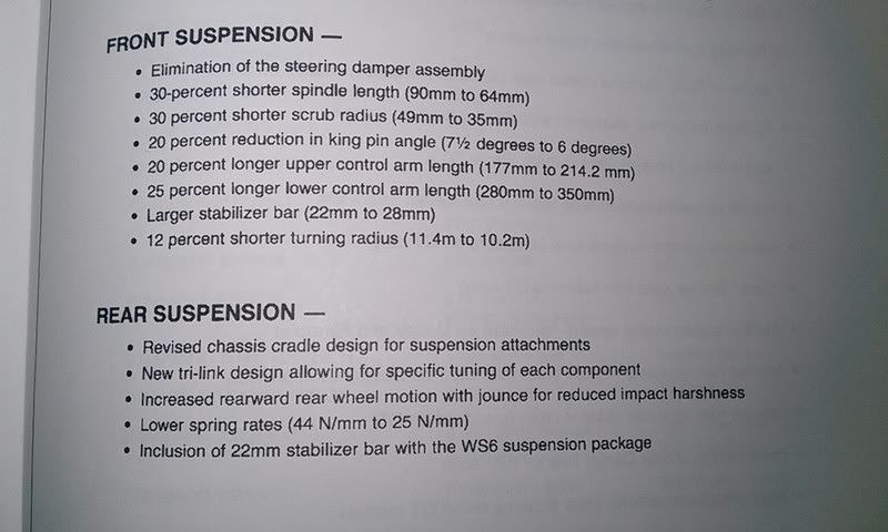
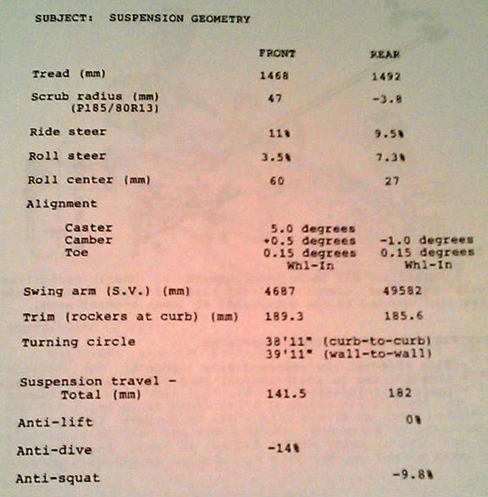
I found some information that would have been more helpful to you when you where making you rmeasurements/drawings of the stock suspension. And to compare to the 1984 models:
Thanks FieroWannabe! I meant to thank you earlier for your second to last post above too, but obviously got sidetracked. I haven't posted in a while, but I've been working up the upper frame rail, strut tower, firewall and trunk sheet metal drawings, as well as the pushrod coilover geometry over the last couple weeks. Things are coming together quite nicely and I'm nearly ready to post my progress. My design will differ from Datsun1972's in some key areas.
I left off with my second to last post thinking I would draw the side and top views of the new upper control arm to finish locating it in three dimensions, but quickly ran into a few roadblocks. The first thing I realized was that I needed to work out the basic location of the new pushrod shock system so as not to interfere with the upper control arm mount. Easy enough I thought... except that to design the pushrod shock system, I needed more details about the structure of the existing frame to make sure the shock and bellcrank mounts could be located in areas of sufficient strength. One step forward, two steps back.
Some of you may recall I measured and drew out the lower frame rail, strut tower, and cradle assembly earlier on, so I "simply" added the upper frame rail, rear cabin structure, and rear upper frame cross member to those drawings. The convoluted shape of the rear cabin structure was the most difficult to measure but I took a page from Yarmouth Fiero's thread and used a single axis laser to give me a straight and level reference line from which to take measurements. I moved it about and changed the orientation to suit my needs. (I apologize for the crappy picture but I had to turn off the camera flash so the laser beam wouldn't be washed out)
Since the rear quarters of the F355 body are already mounted to my '88 frame, I took as many measurements as I could from my '85 parts car frame instead. The only differences are in the strut tower, so I was able to get most measurements directly from the '85. These next three drawings will form the basis for the design of the upper control arm mount and the push rod shock system.
I color-coded the various main structures in the drawings to make the spaghetti of lines more understandable in some of the views. The upper frame rail is in blue, the lower in green, the main cabin structure in red, and the strut tower using bolder black lines than the rest of the components. It's pretty obvious in the top and side view drawings but the colors really help discern what's going on in the rear view drawing. 3D CAD would be really useful here.
The side view drawing (above) shows most of the main structures of the rear chassis quite well, namely; the upper and lower frame rails, which are bridged vertically by the strut tower at the mid point, and by the cabin firewall at their forward points. The upper frame rails are bridged across the car in several locations including the rear-most upper cross member, the strut tower brace, and the upper cabin cross member (all shown in cross section). Finally, the lower frame rails are bridged across the car by the rear bumper (not shown), the rear cradle cross member, and the lower cabin cross member.
Here are the top and rear views:
After having gone through this exercise, it bcame clear that there wasn't much structure aft of the strut towers to mimic Datsun1972's rearward oriented shocks. In fact, much of the structure aft of the strut towers has been deliberately weakened with large holes by the factory to serve as crumple zones in the event of a collision from behind. There being far more structure ahead of the strut towers, I decided to work on a design that would see the shocks run forward toward the cabin. I felt the proximity of the upper and lower rails, plus the cabin upper and lower cross members all located within a reasonable distance of each other at the rear cabin wall would provide ample opportunity to triangulate some rectangular tubing to form the forward shock mount. The other benefit is that by locating the shocks in the engine bay rather than the trunk, the coilovers could bookend the engine quite nicely, peeking out from under the sail panels.
Very nice work Blooz. I wish I was standing there jotting down your measurements as you take them so I could add them to my chassis Rhino model.
I've been toying with the idea of having a series of lasers located around the shop shooting perpendicular lines on the chassis...... but I think they may freak Rosie (the dog) out too much. ha-ha-ha. Also, I wish I had heat in my shop. I have had the engine cradle in my dining room for a while now taking accurate measurements but apparently I'll soon be evicted to make room for the Christmas tree.
Interesting development with the suspension design. Looking forward to more posts regarding this process.
Before being able to determine the location of the new pushrod shock absorber system, I needed to get a better idea how large and what shape the bell crank needed to be. The physical size and shape of the bell crank and the shock absorber would help to determine where they can be mounted or if any compromises would have to be made to package them in the space available.
I did about as much research on the internet on push rod suspension bell cranks as possible only to find very little has been written about the geometry considerations, and no one seems to offer any "off the shelf" designs... likely because of the huge number of variables. So in ploughing ahead with my own design, I discovered through trial and error that pushrod systems have a few design criteria that have to be taken into consideration to work properly. Some are obvious, others not so:
a. BELL CRANK SHAPE. The shape of the bell crank determines the way movement in one plane is transferred into another plane. I knew the bell crank would have to be a 90 degree elbow since I wanted to translate the vertical movement of the knuckle (and pushrod) into a longitudinal (fore-and-aft) compression of the shock absorber;
b. CRANK MOTION RATIO. For those aware of the more common definition of suspension motion ratio (where the location of the spring mount on the upper or lower control arm affects the leverage that a wheel has on the spring) the rear suspension on a Fiero has a nearly 1:1 ratio since the spring is attached directly to the knuckle. It's not exactly 1:1 because of the inward tilt of the struts. On this pushrod system, the pushrod is also going to be attached directly to the knuckle, however, depending how long each bell crank arm is made in relation to the other, the travel of the shock absorber can be made to be the same as the input pushrod travel, or a different amount. A bell crank with arms of equal length results in a 1:1 ratio. That is, 25 mm of wheel jounce gets transferred into 25 mm of shock absorber and spring compression. On the other hand, if the arm attached to the shock absorber were twice as long as the one attached to the knuckle (as in a 1:2 ratio bell crank), then 25 mm of wheel travel would result in 50 mm of spring and shock compression (under proper design conditions).
The internet is full of opinions regarding the "best" crank motion ratio, but some make more sense than others. The rationale I favoured was to make as high a motion ratio as possible within the physical constraints of the engine bay. High ratios allow the shock absorber to pump more fluid in the shock than low ratio motions for every increment of wheel travel movement. That in turn allows finer tuning of the shock absorber valve rates on adjustable shocks. It didn't take long for me to realize though that even a 1:1 ratio would give plenty of shock travel... perhaps even too much. Given 76 mm (3") of jounce and the same in rebound meant 6" of travel even with a 1:1 ratio... that's a lot when you start looking up various shock absorber specs... good thing the frame was stretched an additional 3" back there! So I started out with a 1:1 raito to see where it would take me, knowing that if space allowed, I could always increase or decrease the motion ratio later in the design.
c. PUSHROD TRAVEL TO CRANK ARM LENGTH RATIO. Choosing the right length of the bell crank arms was the next hurdle. I needed to determine the length of the bell crank arms such that the full 76 mm (3") of jounce and rebound travel would not result in any binding or large angular change in the pushrods. It's not as simple as making the crank arms 3" long. To explain why, here's an example of a 1:1 travel to crank arm ratio:
As the wheel would compress upwards, the top end of the input pushrod would progressively be pulled away from the vertical by the rotational movement of the bell crank. By the time the full 76 mm (3") of travel were used up, the pushrod would be at about 22 degrees from vertical, splitting a portion of it's travel between upward, and fore-and-aft motions.
The same thing happens at the shock absorber as well, except that during the last portion of jounce travel a portion of the motion would be used up to swing the shock down rather than compress it. This would effectively lower the spring rate at a point when a higher rate would be desirable to prevent bottoming out.
To reduce the angular change in the pushrod (and shock), the bell crank arms must be chosen such that under the full range of jounce and rebound travel, the input pushrod stays as near to vertical, and the shock absorber stays as near to horizontal as possible. The way to accomplish this is to make the bell crank arms as long as possible in relation to the pushrod travel.
Of course space limitations always muddy up the best design considerations, so given the space under the decklid for a bell crank, I chose the crank arm lengths to be 107 mm long, giving a 1:1.4 push rod travel to crank arm length ratio.
Here is conceptual configuration of the bell crank...
And how I envision it will fit in the engine bay along with the pushrod and coil over shock.
Next, I'll show how the pushrod, bell crank, and shock move in jounce and rebound, followed by a discussion on the strength of materials needed to fabricate the bell crank and the choice of pushrods, hemispherical joints, and coil over shocks to support the estimated loads. Then, of course, how I intend to attach the bell crank and the shock mount to the Fiero frame... so lots more to come.
One more thing with crank shape you may want to consider is the change in motion ratio throughout the suspension movement. You don't have to have the pushrod joint, pivot bearing, and damper joint at a 90* angle. If you were to move the damper mounting location on the crank rearwards but maintain the same vertical height you can get the motion ratio to fall (towards 1:1) with bump which will result in a progressively increasing wheel rate. Essentially you can simulate progressive rate springs with fixed rate ones. Just make sure you don't design it with a falling wheel rate or you'll end up with a lot more body roll and less responsive suspension. Just something to think about.
Before being able to determine the location of the new pushrod shock absorber system, I needed to get a better idea how large and what shape the bell crank needed to be. The physical size and shape of the bell crank and the shock absorber would help to determine where they can be mounted or if any compromises would have to be made to package them in the space available.
I did about as much research on the internet on push rod suspension bell cranks as possible only to find very little has been written about the geometry considerations, and no one seems to offer any "off the shelf" designs... likely because of the huge number of variables. So in ploughing ahead with my own design, I discovered through trial and error that pushrod systems have a few design criteria that have to be taken into consideration to work properly. Some are obvious, others not so:
a. BELL CRANK SHAPE. The shape of the bell crank determines the way movement in one plane is transferred into another plane. I knew the bell crank would have to be a 90 degree elbow since I wanted to translate the vertical movement of the knuckle (and pushrod) into a longitudinal (fore-and-aft) compression of the shock absorber;
b. CRANK MOTION RATIO. For those aware of the more common definition of suspension motion ratio (where the location of the spring mount on the upper or lower control arm affects the leverage that a wheel has on the spring) the rear suspension on a Fiero has a nearly 1:1 ratio since the spring is attached directly to the knuckle. It's not exactly 1:1 because of the inward tilt of the struts. On this pushrod system, the pushrod is also going to be attached directly to the knuckle, however, depending how long each bell crank arm is made in relation to the other, the travel of the shock absorber can be made to be the same as the input pushrod travel, or a different amount. A bell crank with arms of equal length results in a 1:1 ratio. That is, 25 mm of wheel jounce gets transferred into 25 mm of shock absorber and spring compression. On the other hand, if the arm attached to the shock absorber were twice as long as the one attached to the knuckle (as in a 1:2 ratio bell crank), then 25 mm of wheel travel would result in 50 mm of spring and shock compression (under proper design conditions).
The internet is full of opinions regarding the "best" crank motion ratio, but some make more sense than others. The rationale I favoured was to make as high a motion ratio as possible within the physical constraints of the engine bay. High ratios allow the shock absorber to pump more fluid in the shock than low ratio motions for every increment of wheel travel movement. That in turn allows finer tuning of the shock absorber valve rates on adjustable shocks. It didn't take long for me to realize though that even a 1:1 ratio would give plenty of shock travel... perhaps even too much. Given 76 mm (3") of jounce and the same in rebound meant 6" of travel even with a 1:1 ratio... that's a lot when you start looking up various shock absorber specs... good thing the frame was stretched an additional 3" back there! So I started out with a 1:1 raito to see where it would take me, knowing that if space allowed, I could always increase or decrease the motion ratio later in the design.
c. PUSHROD TRAVEL TO CRANK ARM LENGTH RATIO. Choosing the right length of the bell crank arms was the next hurdle. I needed to determine the length of the bell crank arms such that the full 76 mm (3") of jounce and rebound travel would not result in any binding or large angular change in the pushrods. It's not as simple as making the crank arms 3" long. To explain why, here's an example of a 1:1 travel to crank arm ratio:
As the wheel would compress upwards, the top end of the input pushrod would progressively be pulled away from the vertical by the rotational movement of the bell crank. By the time the full 76 mm (3") of travel were used up, the pushrod would be at about 22 degrees from vertical, splitting a portion of it's travel between upward, and fore-and-aft motions.
The same thing happens at the shock absorber as well, except that during the last portion of jounce travel a portion of the motion would be used up to swing the shock down rather than compress it. This would effectively lower the spring rate at a point when a higher rate would be desirable to prevent bottoming out.
To reduce the angular change in the pushrod (and shock), the bell crank arms must be chosen such that under the full range of jounce and rebound travel, the input pushrod stays as near to vertical, and the shock absorber stays as near to horizontal as possible. The way to accomplish this is to make the bell crank arms as long as possible in relation to the pushrod travel.
Of course space limitations always muddy up the best design considerations, so given the space under the decklid for a bell crank, I chose the crank arm lengths to be 107 mm long, giving a 1:1.4 push rod travel to crank arm length ratio.
Here is conceptual configuration of the bell crank...
And how I envision it will fit in the engine bay along with the pushrod and coil over shock.
Next, I'll show how the pushrod, bell crank, and shock move in jounce and rebound, followed by a discussion on the strength of materials needed to fabricate the bell crank and the choice of pushrods, hemispherical joints, and coil over shocks to support the estimated loads. Then, of course, how I intend to attach the bell crank and the shock mount to the Fiero frame... so lots more to come.
do yourself a faver and use the rear suspension from a c6 corvette as i did will give you a wider track and the geometry you want here is the link some good pics of how its made are here midway down the page https://www.fiero.nl/forum/F.../HTML/000007-33.html
Thanks for commenting Zac... you're absolutely right about the changing motion ratio thoughout the suspension movement. I may be well advised to relocate the shock pivot point on the bell crank further back as you suggested. When it comes time, do you believe your Lotus software will be able to analyze a system with a trailing link, two lower lateral links, and an upper control arm (well, two upper links really)?
For Bubbajoe: Thanks for the input and the link. I read through your entire build several years ago. While I admire your innovation and fabrication skills, there are certain aspects of the Corvette front end that leave me wondering how suitable it would be in the rear of a Fiero. Without any analysis it would be difficult to say whether the rear roll center would end up at an appropriate height, nor would it be easy to know how it moved throughout the range of suspension travel. Other issues I'd be concerned about would be that the Corvette front was most likely designed to toe out under compression to induce understeer, while in the Fiero rear the opposite is needed. Then there's issues with the steering tie rod and bump steer, the large amount of anti-squat introduced by those lower control arms, and the transfer of accelerative forces to the frame through control arms that were designed primarily with decelerative forces in mind. By no means do I intend to rain on your parade, but I'm not sure making a Corvette front end work well at the rear of a Fiero would be any easier than what I'm doing now. In fact it might even be more difficult.
[This message has been edited by Bloozberry (edited 12-02-2012).]
There isn't a default template with your configuration but I can probably create a template from scratch or try to modify one that's close already. I'll look into it.
Thanks for commenting Zac... you're absolutely right about the changing motion ratio thoughout the suspension movement. I may be well advised to relocate the shock pivot point on the bell crank further back as you suggested. When it comes time, do you believe your Lotus software will be able to analyze a system with a trailing link, two lower lateral links, and an upper control arm (well, two upper links really)?
For Bubbajoe: Thanks for the input and the link. I read through your entire build several years ago. While I admire your innovation and fabrication skills, there are certain aspects of the Corvette front endl that leave me wondering how suitable it would be in the rear of a Fiero. Without any analysis it would be difficult to say whether the rear roll center would end up at an appropriate height, nor would it be easy to know how it moved throughout the range of suspension travel. Other issues I'd be concerned about would be that the Corvette front was most likely designed to toe out under compression to induce understeer, while in the Fiero rear the opposite is needed. Then there's issues with the steering tie rod and bump steer, the large amount of anti-squat introduced by those lower control arms, and the transfer of accelerative forces to the frame through control arms that were designed primarily with decelerative forces in mind. By no means do I intend to rain on your parade, but I'm not sure making a Corvette front end work well at the rear of a Fiero would be any easier than what I'm doing now. In fact it might even be more difficult.
You're concerns are legitimate, but GM uses the same components on the front and rear of the Corvette. The mounting positions are changed, but they use the same control arms and uprights. So the rear of an c5/c6 vette has the proper anti squat, camber curve and roll steer. It's a pretty well thought out design. The pieces are forged aluminum. And they are readily available, many aftermarket manufactures are using the pieces and geometry for retrofit applications. But I'm sure you can find a good deal of information about the suspension on the web.
Thanks for commenting Zac... you're absolutely right about the changing motion ratio thoughout the suspension movement. I may be well advised to relocate the shock pivot point on the bell crank further back as you suggested. When it comes time, do you believe your Lotus software will be able to analyze a system with a trailing link, two lower lateral links, and an upper control arm (well, two upper links really)?
For Bubbajoe: Thanks for the input and the link. I read through your entire build several years ago. While I admire your innovation and fabrication skills, there are certain aspects of the Corvette front end that leave me wondering how suitable it would be in the rear of a Fiero. Without any analysis it would be difficult to say whether the rear roll center would end up at an appropriate height, nor would it be easy to know how it moved throughout the range of suspension travel. Other issues I'd be concerned about would be that the Corvette front was most likely designed to toe out under compression to induce understeer, while in the Fiero rear the opposite is needed. Then there's issues with the steering tie rod and bump steer, the large amount of anti-squat introduced by those lower control arms, and the transfer of accelerative forces to the frame through control arms that were designed primarily with decelerative forces in mind. By no means do I intend to rain on your parade, but I'm not sure making a Corvette front end work well at the rear of a Fiero would be any easier than what I'm doing now. In fact it might even be more difficult.
the unit i used is the rear suspension unit of a c5 c6 not the front the front is not suited for the rear as you suggest
You're concerns are legitimate, but GM uses the same components on the front and rear of the Corvette. The mounting positions are changed, but they use the same control arms and uprights.
The C5 uprights are the same front to rear (they swap sides as they swap ends), but the a-arms are physically different front/rear.
Originally posted by bubbajoexxx: The unit I used is the rear suspension unit of a c5 c6 not the front. The front is not suited for the rear as you suggest
My mistake... for some reason I thought it was a front suspension assembly... the tie rods threw me off. Still, my goal is to convince my provincial inspection authorities (and ultimately myself) that my modifications are an improvement over the lowered stock Fiero. Swapping out the rear end for any other car's system wouldn't change what I have to do, nor make it any easier IMHO.
With all the fabrication in mind what about lifting the constraint of the stock 88 knuckle and make your own and put the pickup points were they work best for you? Since your going multi-link I'm thinking a simple plate/pan style and hub bearing of your choice would allow you to optimize what you have going on so far.
Great work! The attention to detail is just amazing!
------------------ yellow 88 GT, not stock white 88 notchie, 4 banger
Originally posted by ccfiero350: With all the fabrication in mind what about lifting the constraint of the stock 88 knuckle and make your own and put the pickup points were they work best for you?
That's a valid consideration. I started this exercise with a secondary goal in the back of my mind though: to come up with a system that would be affordable for the stock '88 owner who's looking to lower the rear of his car and improve the kinematics rather than worsen them. Every change I make takes me further from that goal of affordability and new knuckles would add significantly to the cost and complexity of the fabrication.
New knuckles don't appear to be necessary at this stage anyways... the system is nearly worked out, with new mounts and development of the upper control arm geometry well under way. Theoretically, the system appears likely to out perform the lowered stock geometry and also likely better than stock at ride height too (not to mention the wow-factor of an SLA with pushrod shocks). This will be backed-up with Zac's Lotus software analysis, not just a claim made in the wind. At this stage it's still possible that someone might be interested following in my footsteps because so far it's not any more involved or complicated than many builds out there: a bell crank, a knuckle adapter, a couple push rods, a new coil over shock, and some mounts. The elimination of the strut towers is also a bonus for those looking for more room in the engine bay or for kit builders trying to get away from the immediately recognizable Fiero strut tower look. If it works out, the plans and parts lists will be free.
[This message has been edited by Bloozberry (edited 12-03-2012).]
With all the fabrication in mind what about lifting the constraint of the stock 88 knuckle and make your own and put the pickup points were they work best for you? Since your going multi-link I'm thinking a simple plate/pan style and hub bearing of your choice would allow you to optimize what you have going on so far.
Great work! The attention to detail is just amazing!
Don, 355Fiero, built up rear uprights for his 355 build. At one point he sent me the plans, but that was a few years back. not sure what I did with them. I don't think it was specifically for an 88, but I'm sure it could be adapted.
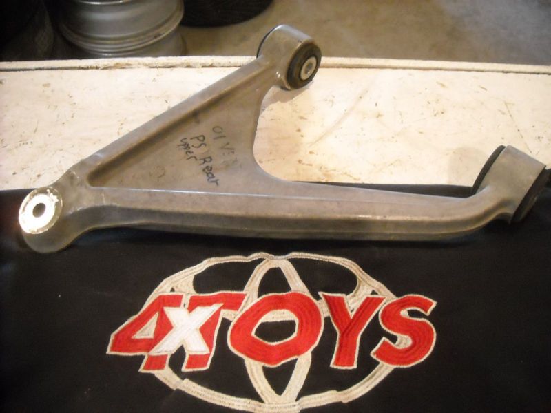
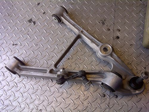
My control arm setup was for a pre 88 as it has the ball joint setup etc. with a 4" extension. I didn't go through the detailed investigation Blooz has been going through. I also sent him any pics and info I had of that work when he was first starting up this investigation.
Now that my 308 is on its way to paint, I am pulling the 355 back into the workshop to finish off and I may well go for a Longitudinal engine/trans and use the suspension setup he is coming up with here.... This setup looks great and would be pretty easy to redo my rear engine bay area to use this. I have a spare 88 rear cradle as well...
Keep up the work Blooz, we are all following closely. I have learned a lot from this thread.
Cheers Don
I thought you were following this thread. Looking forward to seeing your results...
Here are the same drawings as above except with the suspension compressed and extended 76 mm in each direction, superimposed on each other. The blue lines are obviously in jounce (compression) and the red lines are in rebound (extension). I've also shaded in green the areas I was able to determine there would be interference. I know these aren't the easiest drawings to decipher so I'll summarize what I've determined using the higher resolution drawings on my desktop.
Side View:
The side view gives the clearest view of what's happening. As I had already mentioned several pages back, the upper side rail will need to be clearanced to make room for the larger tires and lowered suspension (note the larger green area). I suspect I will simply bump the rail upwards by trimming and boxing the bottom and adding the lost cross section to the top of the rail with new steel.
The smaller green area to the left is where I noticed there will be interference between the bell crank and the spring hat in rebound. I'm not too worried about that since this is only a conceptual spring and shock, not an actual one. It's something to watch for nonetheless. Once the adjustable spring seat is located where it needs to be, several companies offer hats with a greater angle if the interference still exists, or I can simply change the profile of the bell crank in that area.
Rear View:
The rear view shows the extent of the interference with the stock upper frame rail in full jounce. It also shows how little the pushrods change angles making the selection of the rod ends easier since high angle spherical joints are more expensive and more limited in strength.
Top View
The top view has to be the worst to see what's going on with the bell crank and shock, but it is interesting to note how much the rear wheel moves longitudinally and laterally in the wheel well, shortening and lengthening the wheelbase and the track. That's due to the trailing link and lateral links pulling and pushing on the knuckle respectively as they swing through their arcs of movement. This happens on the stock suspension as well.
The next thing to do before designing the mounts for the shocks and bell cranks is to locate the upper control arm in the side and top views. That way I'll be able to take into consideration all of the mounting requirements at the same time and hopefully avoid any problems.
[This message has been edited by Bloozberry (edited 12-07-2012).]
Great drawings Blooz. They contain a tonne of info and I commend your ability to show this in all three views. I don't have much experience with automotive suspension systems so I am going to ask a basic question. Is it possible to design the suspension with a variable rate so that as the geometry approaches the point of interference, the rate increase prevents contact of the components and frame? It seems like 152 mm of total travel is alot as I envision the suspension on a car like this to be much " tighter".
Absolutely. The total amount of travel in jounce and rebound will be kept in check by the right spring choice, and by the springs and sway bar in roll. (I haven't shown how I plan to connect a sway bar yet but I'm working on linking it to the bell crank.) I alluded to it before, but you can use stiffer springs, or a bell crank with a greater than 1:1 ratio, or variable rate springs (wound tighter at one end), or any combination of all three to keep the suspension from travelling through it's full range. It can also be made to be softer at first and get progressively harder the more you roll or jounce as you mentioned would be desireable. Regardless, it's always better to have additional range available than it is to come up short against a bump stop. When that happens, you effectively lose all of your suspension dynamics and you may as well be driving a an ox cart... Haw Bright, haw!
Determining the optimal spring rates for road holding is done by using a formula such as the one found here: www.hypercoils.com/spring-rate-calculator/ as a starting point. This formula determines the best spring rate to keep your wheels in contact with irreguar road surfaces, though it may not give you a spring rate that's to your liking for suspension travel, nor the amount of squat you desire on acceleration. Like everything else, you must make compromises between many variables and choose the spring rate you need to satisfy mulitple objectives. I consciously chose 3" of travel so as not to artificially limit my options at this stage.
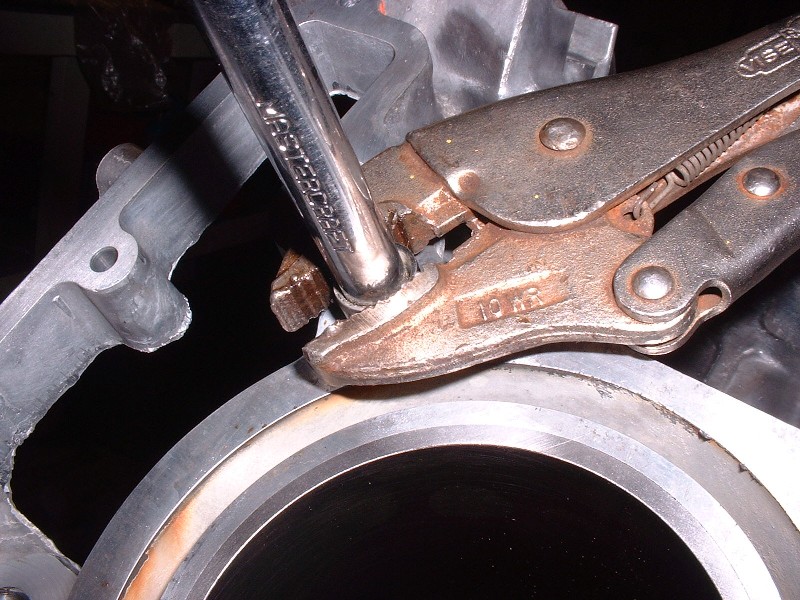
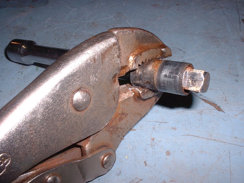
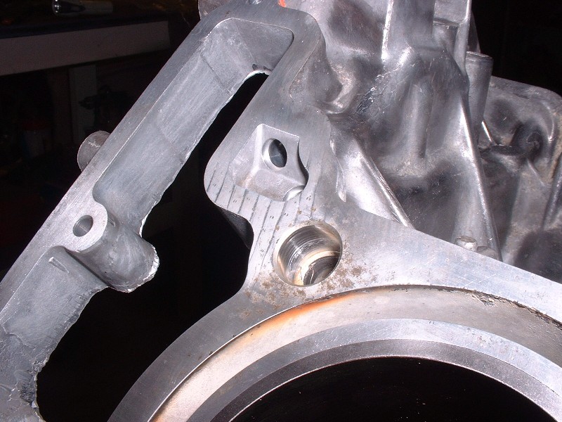
Next up was to remove the four steel head-alignment dowels on the deck surface. They’re swaged in the holes very tightly and are impossible to remove without ruining them. At first I thought they’d come out with a little gentle persuasion, but that gave way to more draconian measures. I’ve seen someone here on PFF remove them by welding a steel rod across the tops and twisting them out that way, but I found an easier method. I used Vise-grips to twist them out but found out that unless you push something into the hollow dowel, the Vise-grips will just deform it and slip rather suddenly. An extension for a 3/8” drive socket wrench fits just right. The extension prevents the dowel from collapsing and from there it was a simple matter of twisting and pulling at the same time. It still took a couple minutes per dowel though.
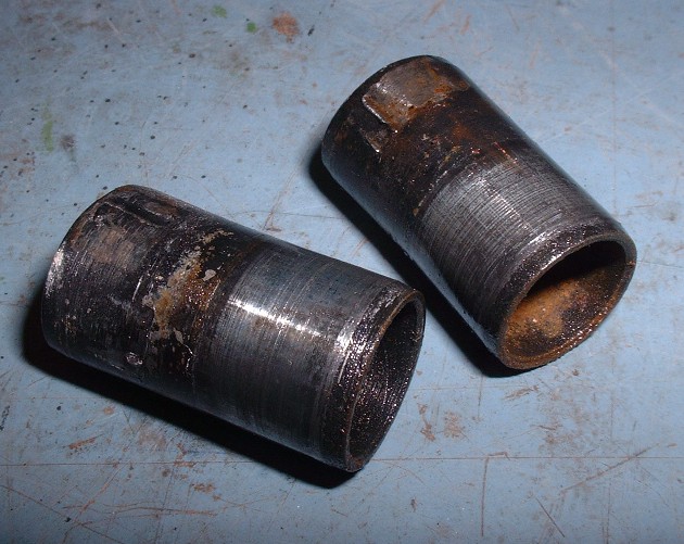
Here’s what they looked like after they came out. Definitely not reusable, and after a quick call to the local dealership, I found out that they wanted $17(!) for each one! And, to top things off, they are discontinued. There were still a few sets here and there across the good ol’ US of A, but I’m certain that shipping, brokerage fees, and taxes would have nearly doubled the price of these puppies. Luckily I have a friend with a metal lathe who turned some new ones for me for $20 labor.
I tried your method earlier tonight. I could get the dowels turning but I couldn't generate any lift. One dowel actually shredded under my visegrip and I guess I'll have to drill out the remains. For the other three I resorted to the steel rod welded across the dowel. It made for easier pulling. The heat may have helped too.
DF
edited to add Sorry to stray off topic here and now back to our regularly scheduled suspension redesign.
[This message has been edited by Dave E Bouy (edited 12-19-2012).]
I joined the forum so I could thank you for sharing your research and scale drawings. I stumbled in here a few months ago through a google search and you have saved me untold hours of work on my project. I join the others who have expressed their appreciation for your hard work and generosity. You are a true craftsman and obviously a perfectionist. Thanks again.
Thanks for the compliment Mike! And welcome to the Forum. The progress is slow and tedious at times, but kind words from complete strangers make it all worthwhile.
When I found your build thread I was looking for information that would help me design a rear frame section using ’88 Fiero suspension pieces and to that end your drawings have been a God send especially since I don’t have a car to take measurements from.
I must admit that initially I didn’t spend much time reading about what you were doing. I just grabbed the pictures and ran but as I worked on my project I kept getting guilt pangs that I should at least thank you for your efforts, if not contribute to your favorite charity (or the car project ) LOL. Well, since I posted the other night I’ve gone back and spent at least six hours reading and digesting what you are doing………and I’m developing a few questions.
A little background is in order. I’m NO suspension expert but I have built a lot of race cars, mainly oval track stock cars, and have worked through a lot of the same issues you are addressing. It’s been awhile since I started from scratch like you are doing, and a lot has changed, but I remember some of the basics and I’m seeing some things that I don’t understand. So how best to engage you on this? Do I post here, or contact you privately? I’m new to this forum and want to make sure that I’m adhering to accepted protocols.
Please feel free to discuss your concerns and ask questions here in the thread Mike. I'm no expert either so input is always welcome. Constructive criticism is the mother of great design.
First off, I’d like to say how much I have enjoyed immersing myself in your build thread. Lots of good information and a lot of really smart and inquisitive contributors here as well. It’s been very thought provoking and fun.
What concerned me most as I began studying your suspension analysis was it seemed at first that you were basing your conclusions about camber gain/loss, roll center location changes, and roll steer fluctuations on measurements taken solely from static bump and rebound. That concerned me because I have found that these measurements are not always the same as those obtained from plotting the suspension pick up points during chassis roll.
As I proceeded through the thread I then saw where you later presented charts and graphs plotting the changes based on body roll. The effects of bump and rebound when driving through pot holes or in straight line braking and acceleration is an important consideration for sure but the effects caused by body roll are, by my way of thinking, a more important consideration. One thing on this before I move on to other thoughts: regarding the rear suspension, did you include the various Chapman strut upper mounting datum point movements during chassis roll in your analysis? Because of the roll center fluctuations inherent in the strut design these points are all over the map and because they are located a long distance from the roll center they move a lot for every degree of roll. This could be significant in your analysis. Perhaps I missed it, but I don’t recall seeing this on your drawings. If these were not included some of your findings might be skewed.
You have invited input and constructive criticism and I hope my comments will be received as such. I don’t want to be perceived as the stranger who shows up in your garage and tells you all you’re doing is wrong. That’s not my intent at all. There are really very few absolutes in building project cars, very few right and wrong ways, and the great thing is that every project is a combination of many disciplines applied with an individual’s own approach and style. In my mind, hot rodding is really an art form and a very personal expression. So my following thoughts and comments are presented as differences in style and in the spirit of “point, counterpoint”.
Okay, so here we go. You seem far more concerned than I would be with the suspension’s bad behavior at roll angles that I don’t think you’ll ever see and might not even be physically attainable with the components you are using. A big old Buick sedan driven into a sharp decreasing radius turn at 100 mph (er, 160 km/h ) might see six degrees of roll but I doubt your car with its low center of gravity, wide stance, and stiff spring/bar package will ever see half of that even if it were to be track driven and I didn’t see that as part of your original design criteria anyway. I would be concerning myself with the suspensions behavior up to about 3 degrees and that’s about it. I would have little to no concern beyond that. With this in mind, most (but not all) of your scenarios fell within what I would consider to be generally acceptable limits within that roll range. Again, maybe not absolutely perfect for track use and not as desirable as say the GT40, but again the car is being built from a production car platform for road use. I think if you did this extensive analysis on even good handling production cars like BMW’s, Corvettes, etc you would find that even they have less than perfect behavior in the extremes of suspension movement.
Personally, in this application I would be more than fine with a camber curve of one degree (or even slightly more) per degree of body roll. The .7 to 1 of the GT40 is great but I don’t think you’d know the difference in this application. If you can get to .7 to 1 without a lot of hassle, fine. If not, get as close as you can without major modifications and call it good. Again, I don’t think you’ll even see three degrees of roll except under very rare circumstances. If you do, you’ll be looking for a revised spring/bar package no matter what the camber is doing. Another consideration is that radial tires actually like a little camber so there’s nothing wrong with a slight increase in static negative camber setting if you need it. I have little doubt that you could add another degree negative to static with negligible effect on tire wear or steering stability, although you might want to increase static toe-in ever so slightly if you do. That would be a seat of the pants trial and error adjustment. One last comment on camber. I do think you are correct in fixing the rear lower control link angle so it is level at static ride height.
I have been fooling around with this stuff for almost 40 years and I’ve grown increasingly skeptical about the conventional wisdom regarding the roll center, and by extension the roll axis, and the dynamic relationship they have with the CG and the various suspension components and, more specifically, the actual effect on weight transfer. Don’t get me wrong, we know that weight transfer occurs and we want to control it in a way that helps us. I’m just not so sure that a migrating roll center is that big a deal, especially in applications such as this. It’s an established fact that strut suspensions produce massive roll center movement. It’s also an established fact that there are a lot of very, very, good performance road cars that use struts on one or both ends and these cars don’t suffer from erratic handling. My friend’s WRX is a great example and the little Lotus that Colin Chapman first put these on was no slouch either.
We also know that dynamically the roll centers and roll axis are constantly moving around, as is the CG, so the moment arm is constantly changing in both length and I suspect also inclination. My personal theory is that the moment arm inclination relative to the force working against it at any given moment in time may be a factor-but I’ve not seen this discussed before so I could be all wet here.
I’m extremely intrigued with the force based roll center principles discussed by Bill Mitchell in the paper referenced by FieroWannaBe. I had not heard of this before but I have suspected that there was something else going on. Maybe this is it. I’ll have to find time to study this more. Thanks FieroWannaBe! Anyway, I’m of the opinion that in your application, or mine for that matter, that the roll center migration is worthy of note, and perhaps should be addressed within practical limits, but not enough to cause dramatic redesigns given the original project design criteria. If we were going F1 or Indycar racing it would be a different deal. Again, this is my opinion but I do also respect yours.
A quick mention here re: anti squat and dive. I agree with FieroWannaBe in that I don’t think you need to be overly concerned with it. Just design into whatever you end up with for rear suspension about the same as original factory and call it good. If you felt that you needed a little leeway just in case of axle tramp you could design in multiple forward trailing link mounting points (or provide for them). And leave the front alone. I don’t think dive will be an issue for you. I also agree with FieroWannaBe about roll axis and static rear roll center heights. Stick with about stock and you’ll be fine. You will probably do fine with a relative flat roll axis for the reasons he mentioned. As a side note, although I have met Herb Adams, and have actually bench raced with him at his shop/house many years ago, I have not read his book but your assessment of him is correct. His background has been primarily with front engine solid rear axle vehicles so you are correct in being cautious applying some of his recommendations to a mid-engine IRS car. Make no mistake, he is a very smart and accomplished engineer but some of what he is saying may not apply to what you are doing.
In summation, the areas that I personally watch closely in these types of projects are tire choice, camber curves that I may have messed up by lowering, brake bias, scrub radius if I’ve changed wheel offset, and especially roll steer. I try to keep the CG as low as I can (without tearing the car apart), the track widths wide, and let the tires do the rest.
Ok, I've prattled on long enough. So again, I applaud your project and sincerely thank you again for your incredibly unselfish sharing of your drawings and research. I plan to stop back by from time to time to see how you are progressing.
Best Regards (and Happy New Year!) Mike
PS. Can you or one of your readers give me approximate dimensions for a stock '88 Fiero rear sway bar (eye to eye, arm length, and diameter)? I haven't been able to find one or reference for this information. I'd like to see what rate was stock and decide if that will work for me. That will give me a starting point if I need to make my own.
[B] PS. Can you or one of your readers give me approximate dimensions for a stock '88 Fiero rear sway bar (eye to eye, arm length, and diameter)? I haven't been able to find one or reference for this information. I'd like to see what rate was stock and decide if that will work for me. That will give me a starting point if I need to make my own.
I would measure an 88 rear bar for you, but that's the only 88 rear suspension piece not sitting ok my garage floor right now, but R Runners pieces are top notch, and have about any range you need. I do have a low opinion of heavy rear bars in an open-diff RWD car though and there tendancy to pull up on the inside wheel. I agree that expecting 6 degrees of role is an unreleastic expectation. But as a design engineer by trade, I feel to not take the time to analyze a system at all conditions, even the most extreme, is inviting critical errors into the system. One thing I would also see as a benifit to Blooze's analysis' would be the effect of bushing deflection, as it can be very significant. But is see no fault to design something to 10 tenths, perfection cannot be reached, but it can be approached, and the reward is knowing nothing was left on the table. If the suspension is capable of 3 inches of jounce and bump it can, somehow, achieve roll at those 3 inches.


 I can post the drawings if anyone wants to see the results, but if not I'll just move onto what I came up with instead.


 )
)