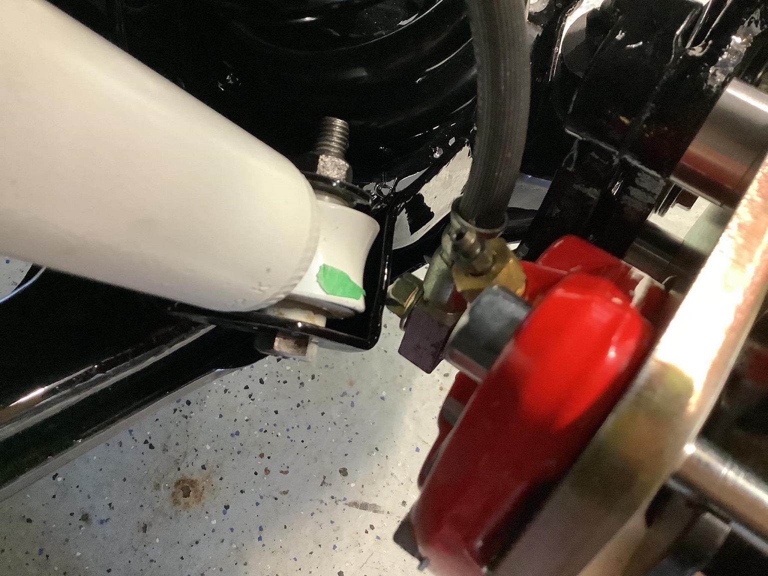
With the Wilwood 120-11872-RD calipers, the banjo bolt hits the damper mount on the LCA, at full droop / full lock:
To address this, I started by reducing the head height of the banjo bolts, but that wasn't enough.
The Wilwood caliper I have is actually made for a 1.04" thick rotor, so with the 0.87" thick LeBaron rotor, the caliper is excessively wide.
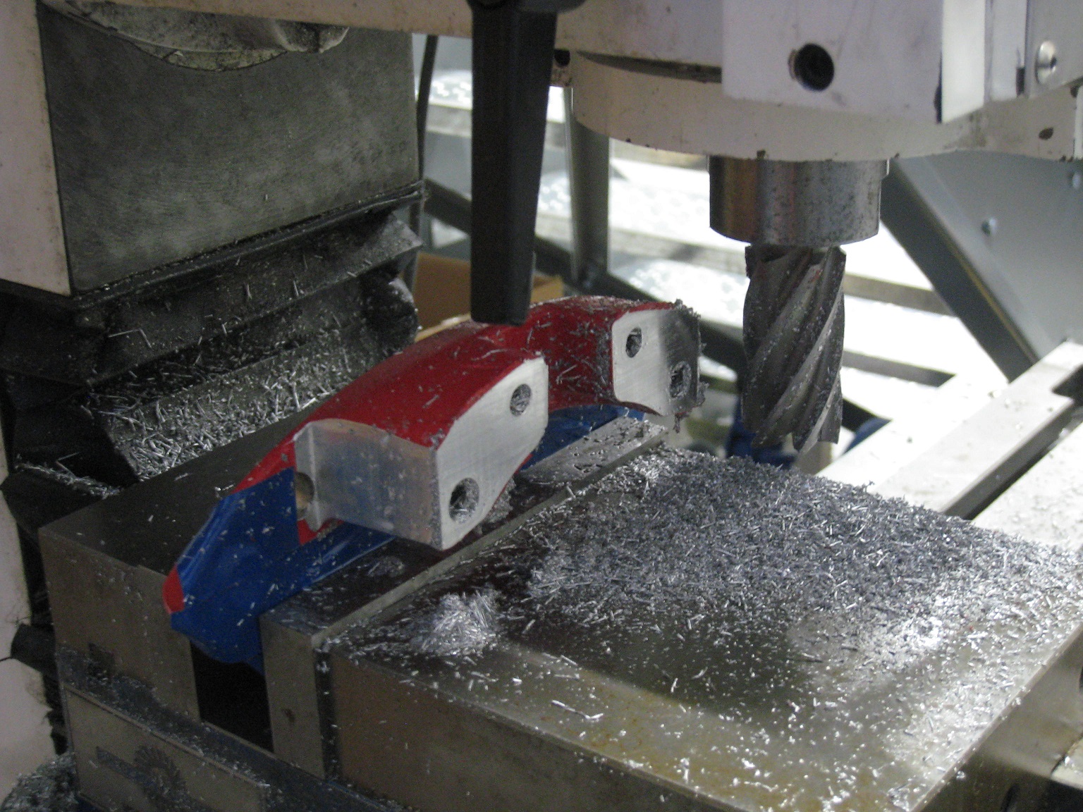
To gain banjo bolt clearance, I decided to narrow the caliper by removing 2.5 mm of material from the outer half:
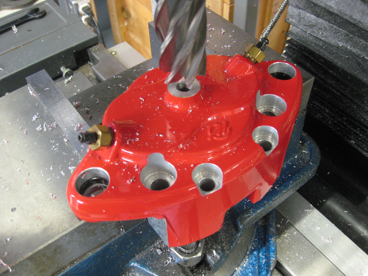
For more banjo bolt clearance, I also removed 3.5 mm of material from the banjo bolt boss:
I plunged the cutter in the Z-axis, so any machining marks would be circular around the banjo bolt, to avoid creating any radial leak paths.
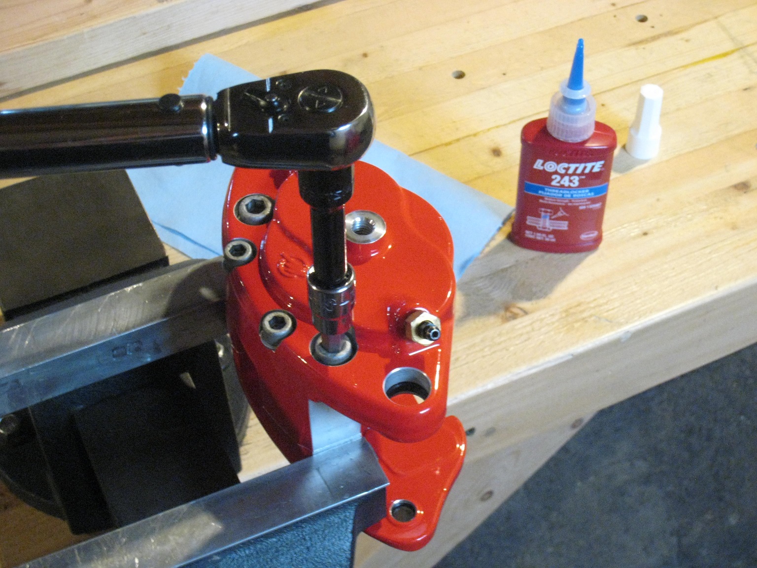
Then, I bolted the calipers back together:
Next weekend I'll be able to bring the calipers to the car and see how much the banjo bolt clearance situation has been improved.
Since it looks like I'm going to be replacing my sluppy123 hubs with custom hubs, if I need to gain more banjo bolt clearance, I may also draw my custom hubs with some positive offset to push the wheel/caliper a bit more outboard.
With the following mods, I finally have 4 mm of clearance between the banjo bolt and LCA: 2.5 mm removed from outer half of caliper. 3.5 mm removed from fluid port boss on caliper. Banjo bolt head reduced in height. Material ground off from LCA.
That's all with a stock sluppy123 hub.
I think that 4 mm clearance is OK, but if I end up making custom hubs, I'll add a bit more positive offset.
For my front hubs, I'm going with modified front rotor/hubs.
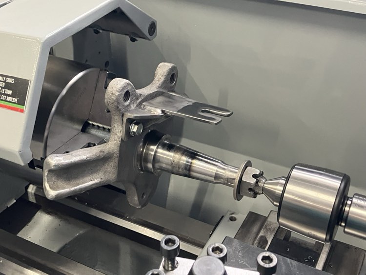
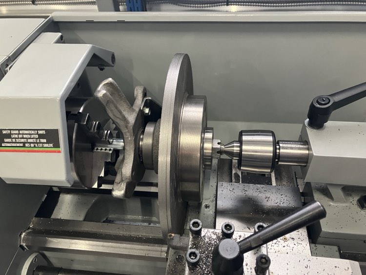
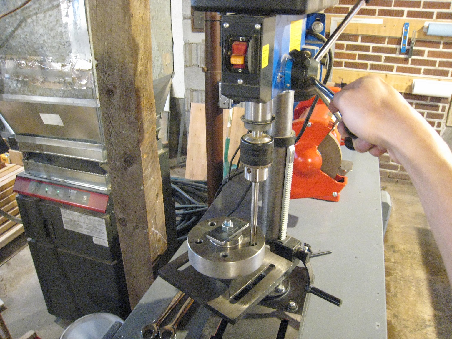
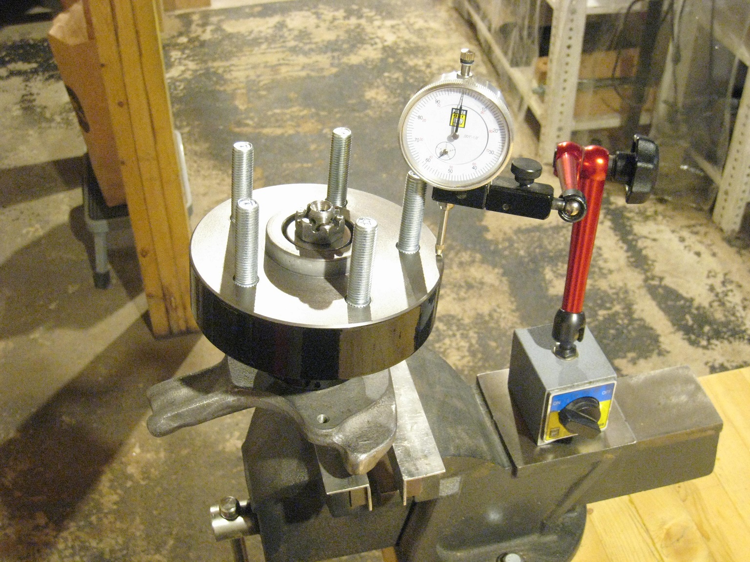
To set up the stock rotor on the lathe, I used a (modified) steering knuckle as a fixture. The steering knuckle is centre-drilled at both ends from the factory.
I crudely statically balanced the steering knuckle by balancing it on one of its centre holes. For torque transmission, I added a steel bracket, which drives one of the hub's ribs.
The setup worked fine without vibration at 150 RPM.
Originally posted by Will: You located it on the bearing races to minimize runout in the final part? Are you planning to face the wheel mounting surface?
Looks like a lot of extra work vs. chucking on the inboard journal, if all you're doing is parting off the rotor
Or are you turning the rotor down from its original OD?
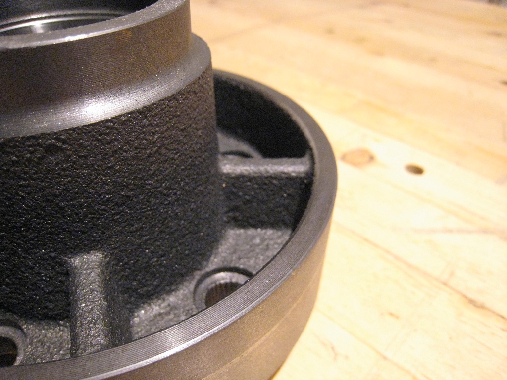
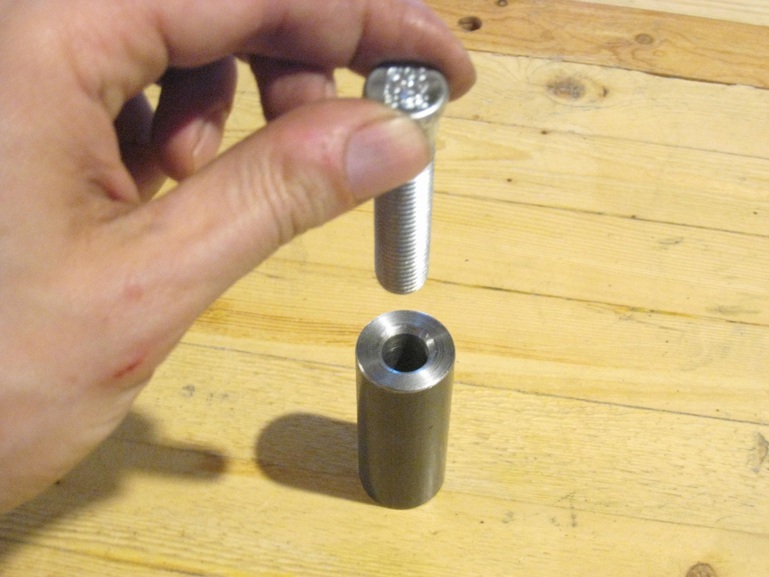
The LeBaron rotor centrebore is slightly large for the Fiero hub's wheel/brake register, so my plan is to build up the area with a Permatex Steel Weld (a steel-loaded epoxy), and then turn it down to fit the LeBaron rotor. This operation needs to be low-runout, so that's why I prepared the setup with location via the bearings. If the brake rotor is mounted eccentrically, then that will cause a static mass imbalance.
Yes, I will be skimming the wheel/brake mounting surface. Initially, that was not part of the plan, but the yahoos at Dynamic Friction (or at the Chinese factory where the rotors were produced) installed the lug studs with an excessive amount of interference (approx 0.025"). This caused some material to be displaced, proud of the surface, hence needing to take a skim cut to make things flat.
As the lug holes are undersized, I'll be able to ream them to 12.5 mm and install Dorman 610-323 studs.
In my previous post, I simply converted the braking surface into a pile of chips. That operation didn't need much precision, but I wanted to do a "shakedown run" of my knuckle / bearing-locating setup, before using it for the more fussy higher-precision operations.
The LeBaron rotor centrebore is slightly large for the Fiero hub's wheel/brake register, so my plan is to build up the area with a Permatex Steel Weld (a steel-loaded epoxy), and then turn it down to fit the LeBaron rotor. This operation needs to be low-runout, so that's why I prepared the setup with location via the bearings. If the brake rotor is mounted eccentrically, then that will cause a static mass imbalance.
The front LeBaron rotor has a smaller rotor pilot than the rear rotor. It's also slightly smaller outside diameter, but it fits the Fiero rotor pilot without modification, IIRC.
In my previous post, I simply converted the braking surface into a pile of chips. That operation didn't need much precision, but I wanted to do a "shakedown run" of my knuckle / bearing-locating setup, before using it for the more fussy higher-precision operations.
I guess if you only need to make two, that's a fine way to do it... a part-off tool would be MUCH easier.
Originally posted by Will: I guess if you only need to make two, that's a fine way to do it... a part-off tool would be MUCH easier.
Besides having to buy (or grind) a tool to do that, I didn't want to deal with the disc coming loose at the end of the cut and possibly smashing/jamming into something.
I also thought about roughly cutting off the disc with an angle grinder + abrasive cutoff wheels, but that would have required many cutoff wheels, and I would have been left with a polygon shape needing to be turned on the lathe. I don't really like cutting polygons into round shapes; I'm not a fan of interrupted cuts like that.
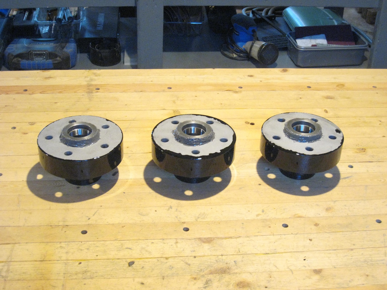
For three hubs (I wanted a spare!), the method was workable, but tedious.
Ideally, I think it would be best to use an endmill to mill a groove to separate the disc from the hub; either conventional mill with rotary table, or CNC. I didn't have either of these tools at my disposal.
quote
Originally posted by Will: The front LeBaron rotor has a smaller rotor pilot than the rear rotor. It's also slightly smaller outside diameter, but it fits the Fiero rotor pilot without modification, IIRC.
That's a good suggestion / good info.
I looked at pics on Rockauto, and it seems like that rotor has a rather shallow rotor hat. My caliper-to-wheel clearance is quite tight as things are now; I think that might turn into interference with the front LeBaron rotor! I'll stay on my current path for now.
The Grizzly Rotary table has been a great addition to the Bridgeport at work, not too expensive either, and nice for making cuts that are not 90* to one another in addition to doing circular things. Can be mounted vertically or horizontally.
The other way you could have rough cut the rotor off is with a jig saw and a steel cutting blade, it does a decent job, I have done some circular cuts in 0.25" steel with it. Not the speediest operation but much better than using cutoff wheels.
Nice work though, hope you get to enjoy the car this summer now that you have your hubs sorted, I am very curious to hear about how you like the car with your anti dive mod, I would like to do something similar.
Besides having to buy (or grind) a tool to do that, I didn't want to deal with the disc coming loose at the end of the cut and possibly smashing/jamming into something.
I also thought about roughly cutting off the disc with an angle grinder + abrasive cutoff wheels, but that would have required many cutoff wheels, and I would have been left with a polygon shape needing to be turned on the lathe. I don't really like cutting polygons into round shapes; I'm not a fan of interrupted cuts like that.
Sounds like you're talking about making the cut axially through the rotor. I'm talking about making the cut radially through the hat section.
Originally posted by zkhennings: Nice work though, hope you get to enjoy the car this summer now that you have your hubs sorted, I am very curious to hear about how you like the car with your anti dive mod, I would like to do something similar.
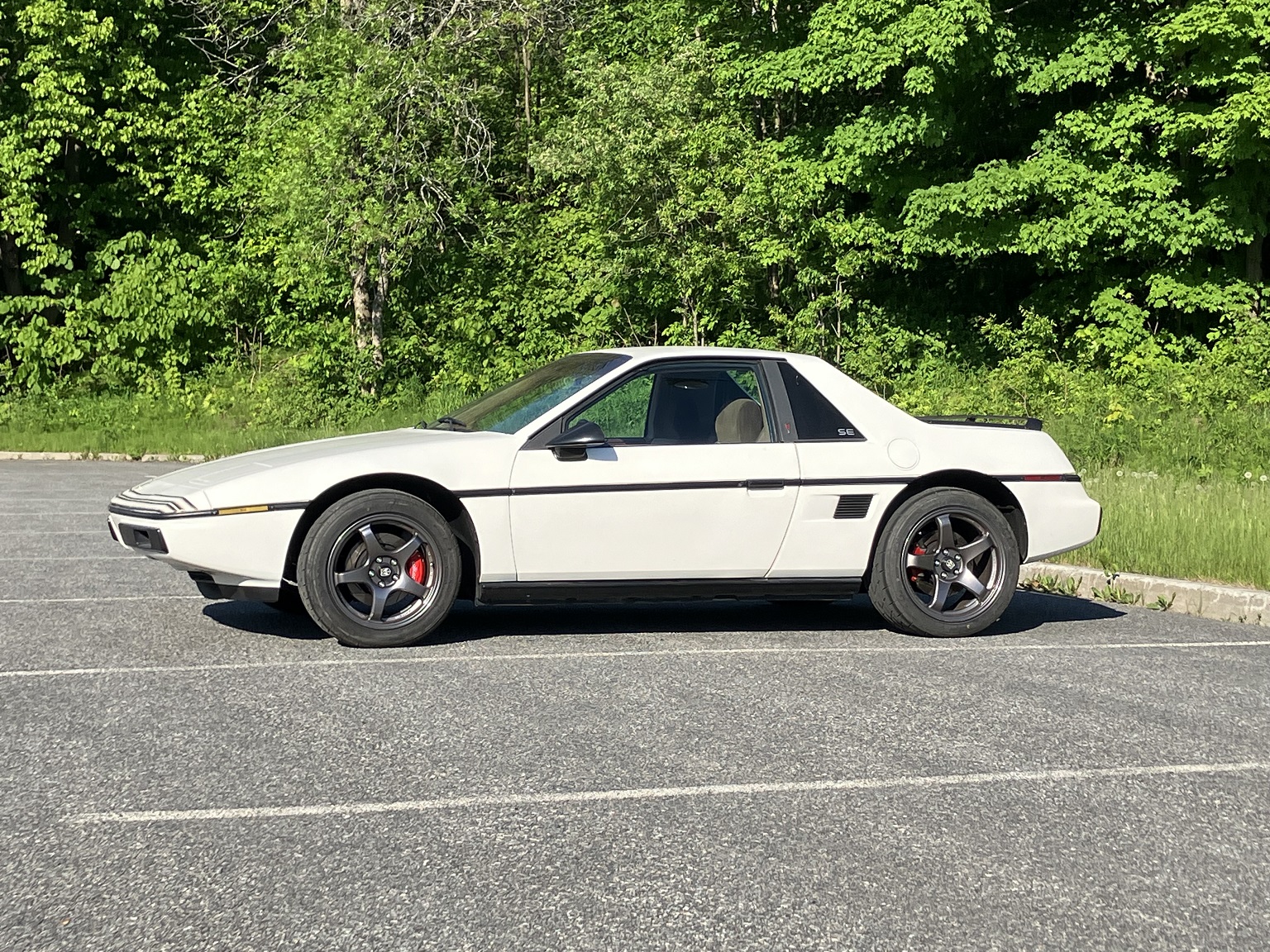
The snow is melting fast, so I'm quite looking forward to the summer and getting the car ready!
quote
Originally posted by Will: Sounds like you're talking about making the cut axially through the rotor.
Yes, that's what I meant.
quote
Originally posted by Will: I'm talking about making the cut radially through the hat section.
I see what you mean; in your proposition, the ribs keep the disc attached to the hub. Then, as a second step, the ribs could be cut with a small cutoff wheel to free the disc.
I wanted to keep the hat+rib area intact, as I wasn't sure how much material could be removed from there while keeping the hub strong enough. In comparison though, the rear hubs are a lot more flimsy-looking, yet they seem adequately strong.
[This message has been edited by pmbrunelle (edited 03-08-2024).]
Did not realize it was just for the rotors, I wouldn't expect any issues then. I was speaking more to the ability of the metal reinforced epoxy to chip because it is pretty hard, almost like a ceramic, and I have had it chip/crack on me before. The plastic rings are soft enough they will not chip, but they are a pain as eventually they don't fit as snug, I have had to glue mine into my wheels after a few years where they used to stay installed from friction. But removing/installing rotors is much more gentle than removing/installing wheels.
For a few weeks this summer I wasn't able to drive my Fiero.
When the engine was stopped, I did an incorrect manipulation with my laptop computer in TunerStudio, and I (unknowingly) injected water into the engine while it was stopped. When I tried to restart the engine, I hydrolocked it and busted the starter and ring gear.
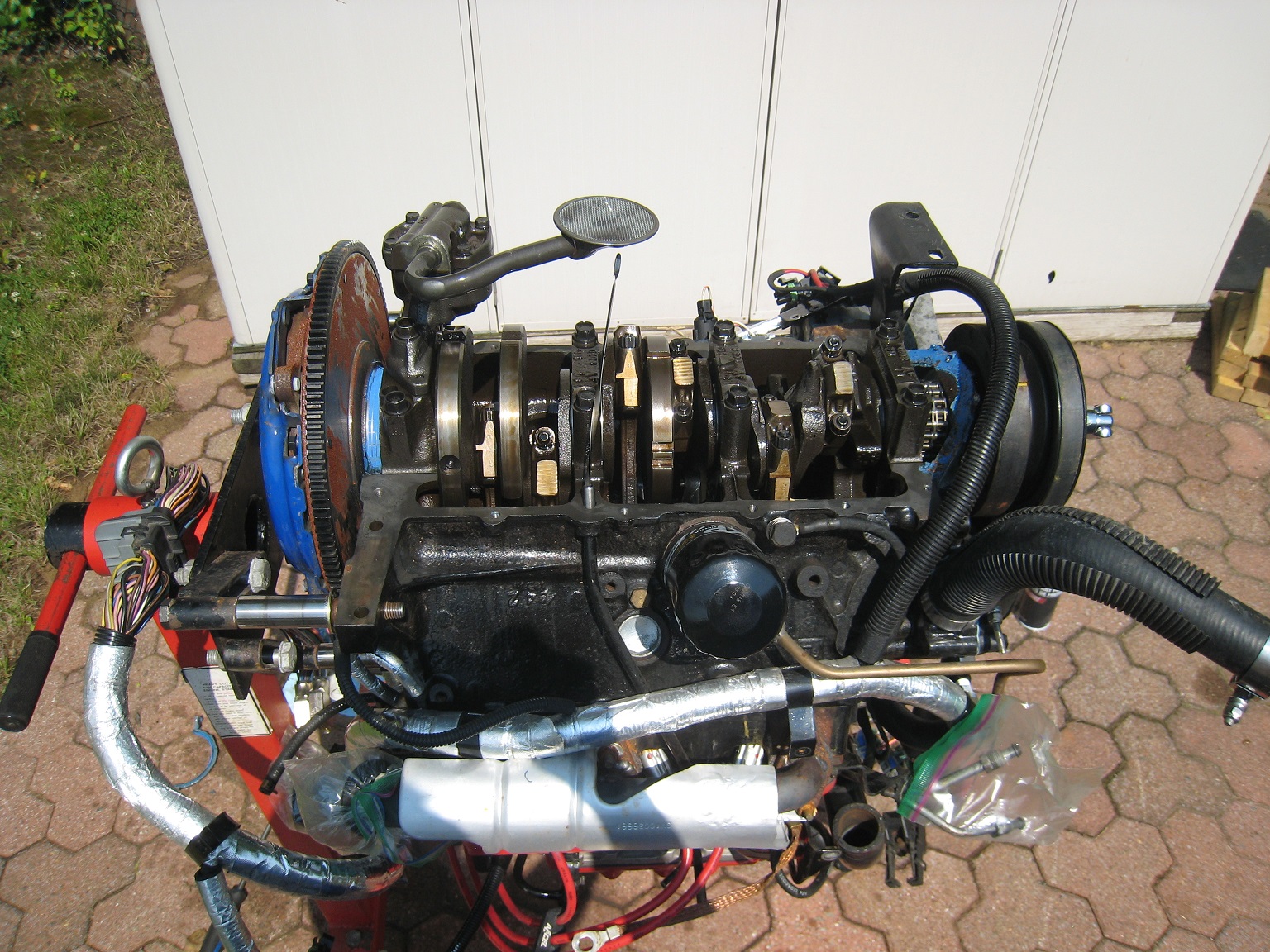
The engine had to come out to replace the flywheel!
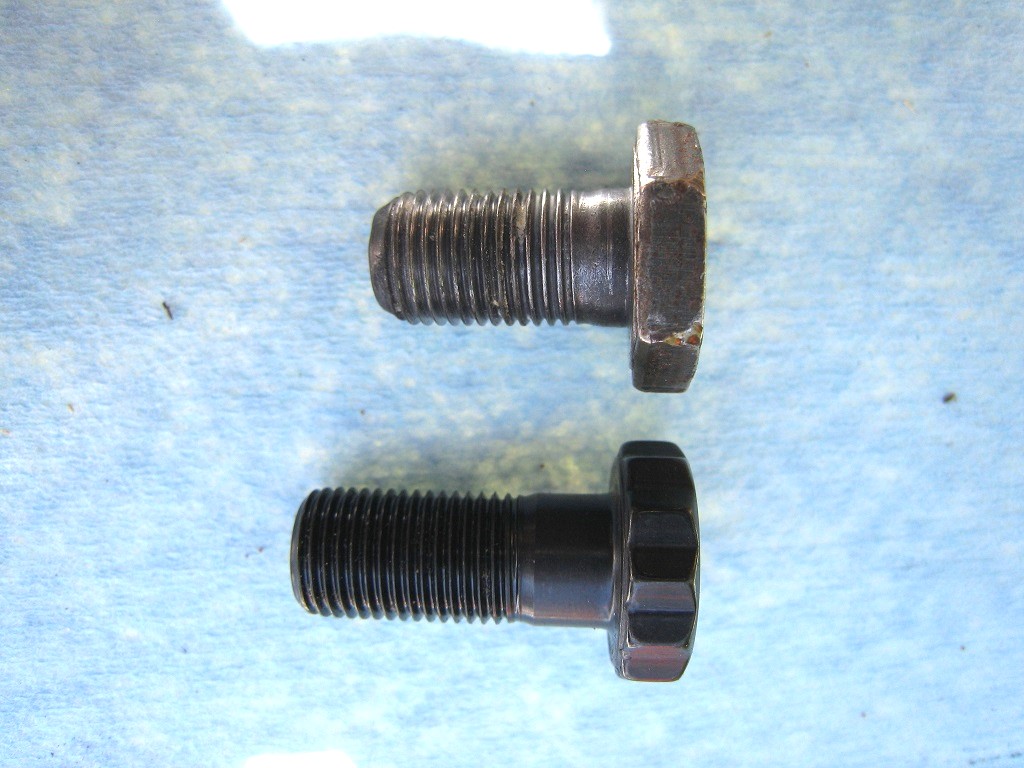
As I shopped for replacement flywheel bolts (a good practice to replace heavily tightened bolts on a critical joint), I figured out that I had been running the wrong bolts; I had been using flexplate bolts for an automatic transmission Fiero. Back in the day, I reused (without thinking too much) the bolts from my manual transmission donor car that the previous owner installed (never trust previous owners).
The flexplate is thinner than the flywheel, so automatic transmission cars use shorter bolts in that location. I used ARP 102-2803 for the Nissan SR20DE/DET.
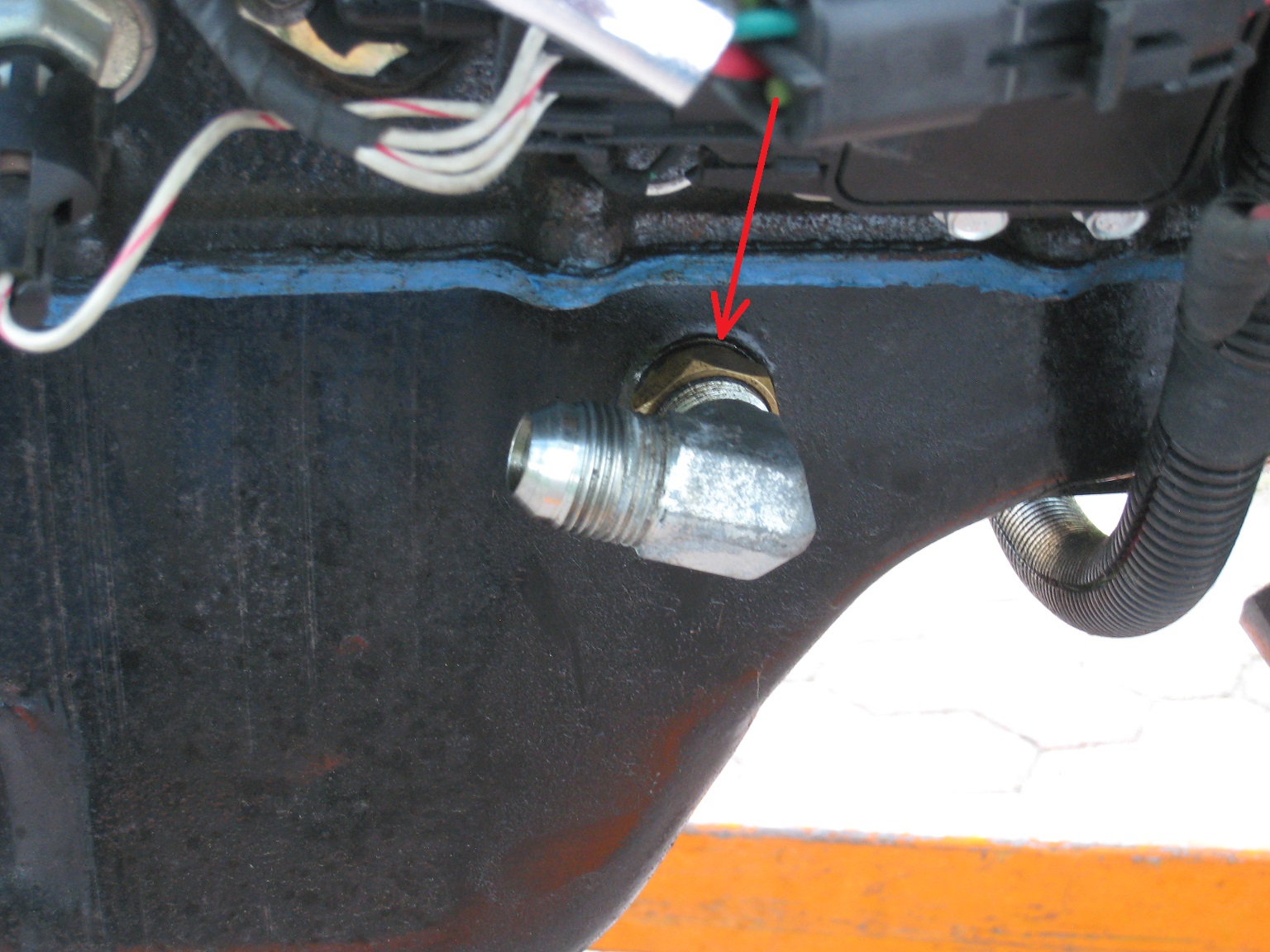
Upon reassembly, I then noticed that the solder joint of my brass turbo oil drain fitting had cracked. This was a fire risk and needed to be addressed. Good thing I saw it...
Since the oil pan was off, I was able to see that the connecting rods were still straight and had the usual endplay. Looks my my hydrolock incident didn't damage anything...
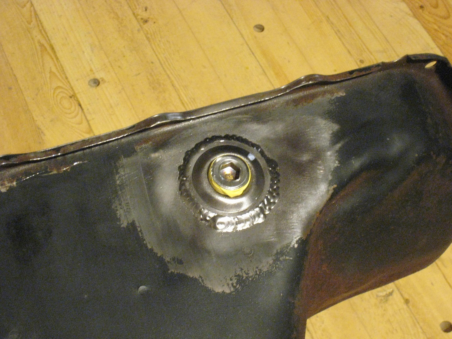
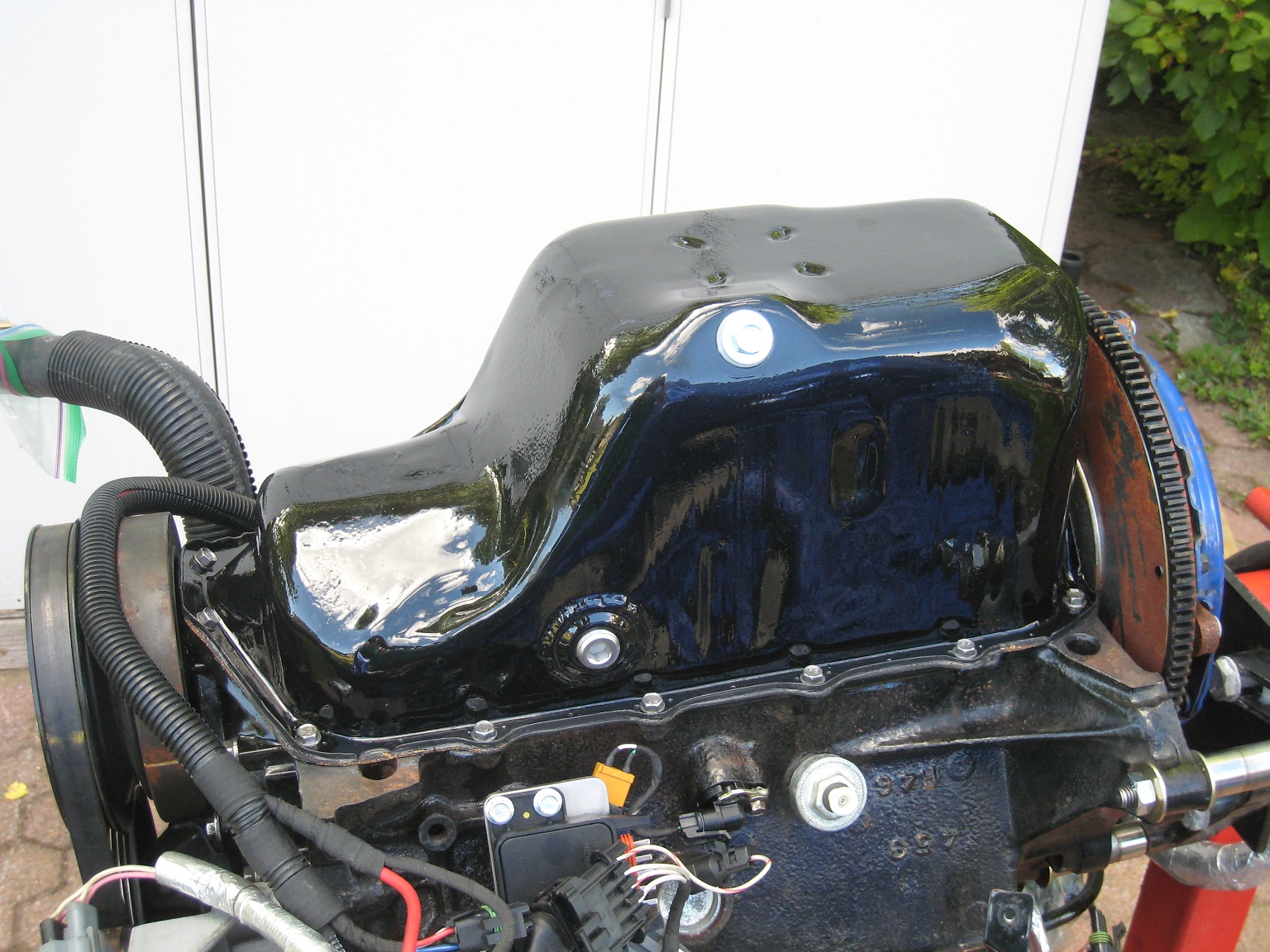
With the oil pan installed:
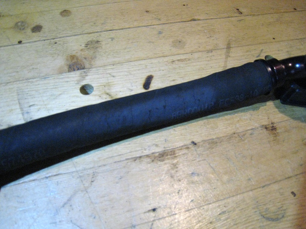
Then, continuing assembly, I noticed that my rubber turbo oil drain hose had burned in one area from radiation from my Y-pipe:
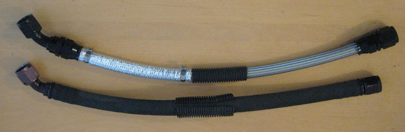
I made a replacement line from PTFE hose, and I installed a fibreglass reflective heat sleeve over the heavily radiated area:
Here is the oil drain line installed:
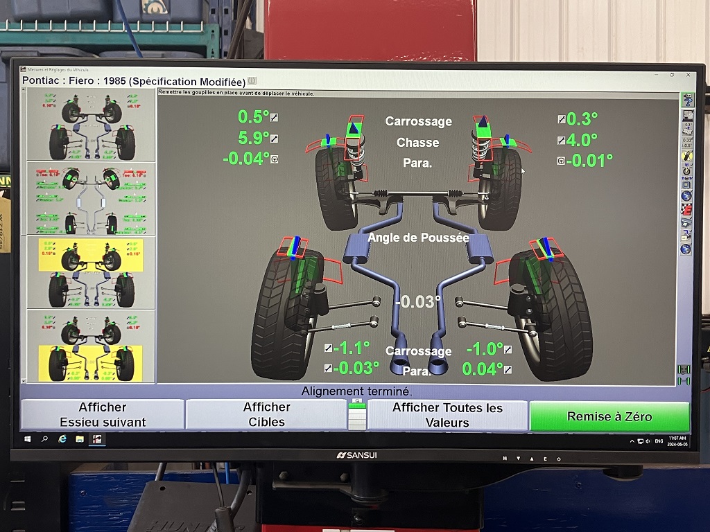
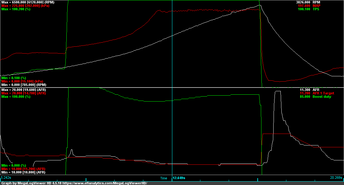
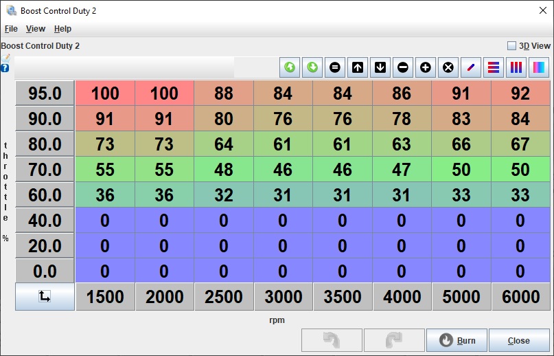
Now that I managed to get the water injection working without hydrolocking the engine, I did myself a 200 kPa MAP tune:
I am currently using open-loop boost control.
Manifold pressure is not stable with temperature (perhaps 15 kPa more pressure in colder weather), and also varies depending on gear.
My next step is to set up closed-loop boost control in order to stabilize the manifold pressure.
Once I have a good closed-loop boost control, then I think I can try increasing the boost.
I expect to replace the springs in the wastegate actuator for a stiffer spring, as the boost control solenoid duty already reaches 92%.
my car has an F23. I've never driven a 4 speed Fiero, so I can't make comparisons to that, however, I have driven my car with both a 3.63 final drive, and a 3.94, unfortunately, the gear ratio wasn't the only change, and it was probably a year apart. I do remember the 3.94 rapping out quickly, IIRC the one I had in the Gran Damn would routinely get put in fourth at sub 30 MPH, and still be able to reasonably accelerate to highway speeds.
I have a metric, and ecotec F23 in the garage that I plan to take apart soon and build a backup for my car, if you need measurements or pictures, let me know.
There's also the F40, but it has a whole list of issues to install in a Fiero.
------------------ "I am not what you so glibly call to be a civilized man. I have broken with society for reasons which I alone am able to appreciate. I am therefore not subject to it's stupid laws, and I ask you to never allude to them in my presence again."
I invited Lou Dias to trash me in my own thread, he refused. sorry. if he trashes your thread going after me. I tried.
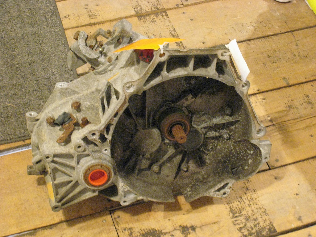
I guess I now have a winter project to put it in the car!
Front transmission mount seems tricky to implement in the stock Fiero location, from lack of mounting bosses on the transmission case. I see why 262 uses a flat metal plate on the bellhousing with a transmission mount relocated on the crossmember.
Just from looking at the stock ratios I think I will like it; it is a has a similar kind of gearing as my M19 gearing with a low 1st gear to help econobox engines move a car off the line. The F23 also has fancy double-cone synchros, etc.
I think the 4-speed Muncie synchros are not so great; shifting feels like it takes forever in the higher RPMs (especially 1->2) when I'm in a hurry. Perhaps my metallic clutch disk has more inertia than a stock disk, exacerbating this issue.
quote
Originally posted by ericjon262: I have a metric, and ecotec F23 in the garage that I plan to take apart soon and build a backup for my car, if you need measurements or pictures, let me know.
I will keep that in mind, thanks.
[This message has been edited by pmbrunelle (edited 09-17-2024).]
The metric bellhousing F23 has a 3.94 final drive. IIRC: The Ecotec F23s have 3.84 final drive The early Cobalt XFE transmissions have a 3.73 final drive The later Cobalt XFE transmissions have a 3.63 final drive.
The early HHR transmissions have a 4.17 FD, and the Vue transmissions have a 4.41.
All boxes have the same shifted gears, except the Vue which has a 0.81 fifth.
The 3.63 transmissions have very nearly the same overall ratio set as the Fiero 282.
The bellhousing side of the differential housing has FAR more bracing on the F23 than it does on the 282... The most common failure mode of the 282 seems to be breaking the differential bearing out of the case on that side due to axial loads from the final drive mesh.
I have noticed the same things you have about mounting the metric bellhousing transmission "Fiero style". I was expecting that I'd grab the front mount bracket from https://thelinsellsdotcom.wordpress.com/ (or is it https://thelinsells.limitedrun.com/ ?) and add to/modify it to pick up some other bolt holes on the bellhousing.
[This message has been edited by Will (edited 09-19-2024).]
Originally posted by Will: I have noticed the same things you have about mounting the metric bellhousing transmission "Fiero style". I was expecting that I'd grab the front mount bracket from https://thelinsellsdotcom.wordpress.com/ (or is it https://thelinsells.limitedrun.com/ ?) and add to/modify it to pick up some other bolt holes on the bellhousing.
It looks like Roger Thelin has a rear bracket that will work, but I probably have to contact him to be sure.
I don't think using a Roger Thelin front mount would be a useful starting point; not much of it would remain after adaptation to the Metric bellhousing transmission.
ericjon262 uses a transmission mount near the bellhousing plane, but then the transmission mount force is applied closer to mid-span of the cradle crossmember. In this case, I think the crossmember should be reinforced/stiffened, or replaced with something more beefy (as he has done).
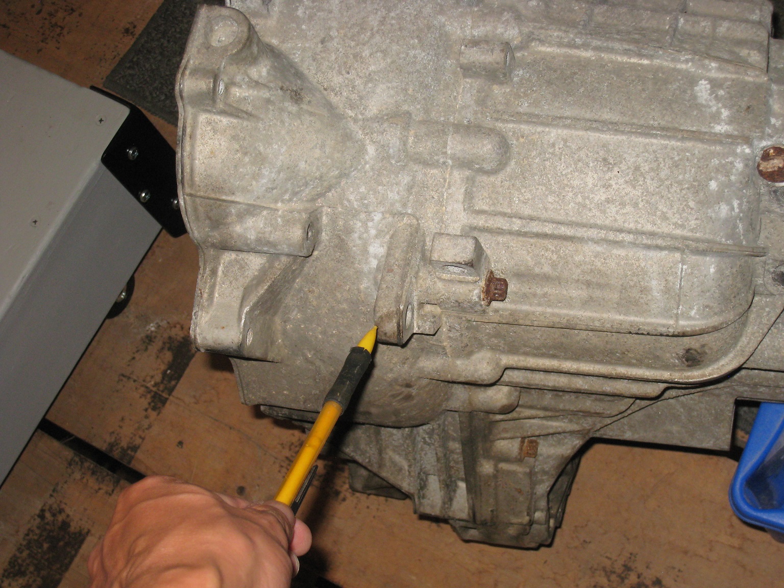
I noticed this ear on the transmission case which is sort of close to the Fiero's front transmission mount.
It might be able to handle the brunt of the transmission mount force.
I need to do a strength evaluation of this ear to determine if it is feasible to make a mount bracket that transmits force mainly to this ear... I guess assuming some aluminium die-casting alloy such as A380. My car is traction-limited in 1st gear. I am not sure how to estimate the force on this mount; I need to think about it.
Those who have selected the "beam" solution perhaps thought that the ear was too flimsy, so they avoided using it.
I'm not a fan of that boss, IIRC, it's for the HTOB hydraulic line. If you look on the end of the transmission, there are 2 sets of bosses, one with two bolts going in horizontal, and one with three going in vertically, the more or less line up with the front driver's side cradle rail and would probably make for a significantly more substantial mount than the boss you pointed at, however, it doesn't line up with any existing mount location.
Edit: I seem to have forgotten the horizontal bolt bosses are not on the same plane, the planes are approximately 48mm apart.
this is the mount I had come up with for my 5 speed swap in the Gran Damn.
------------------ "I am not what you so glibly call to be a civilized man. I have broken with society for reasons which I alone am able to appreciate. I am therefore not subject to it's stupid laws, and I ask you to never allude to them in my presence again."
I invited Lou Dias to trash me in my own thread, he refused. sorry. if he trashes your thread going after me. I tried.
[This message has been edited by ericjon262 (edited 09-21-2024).]
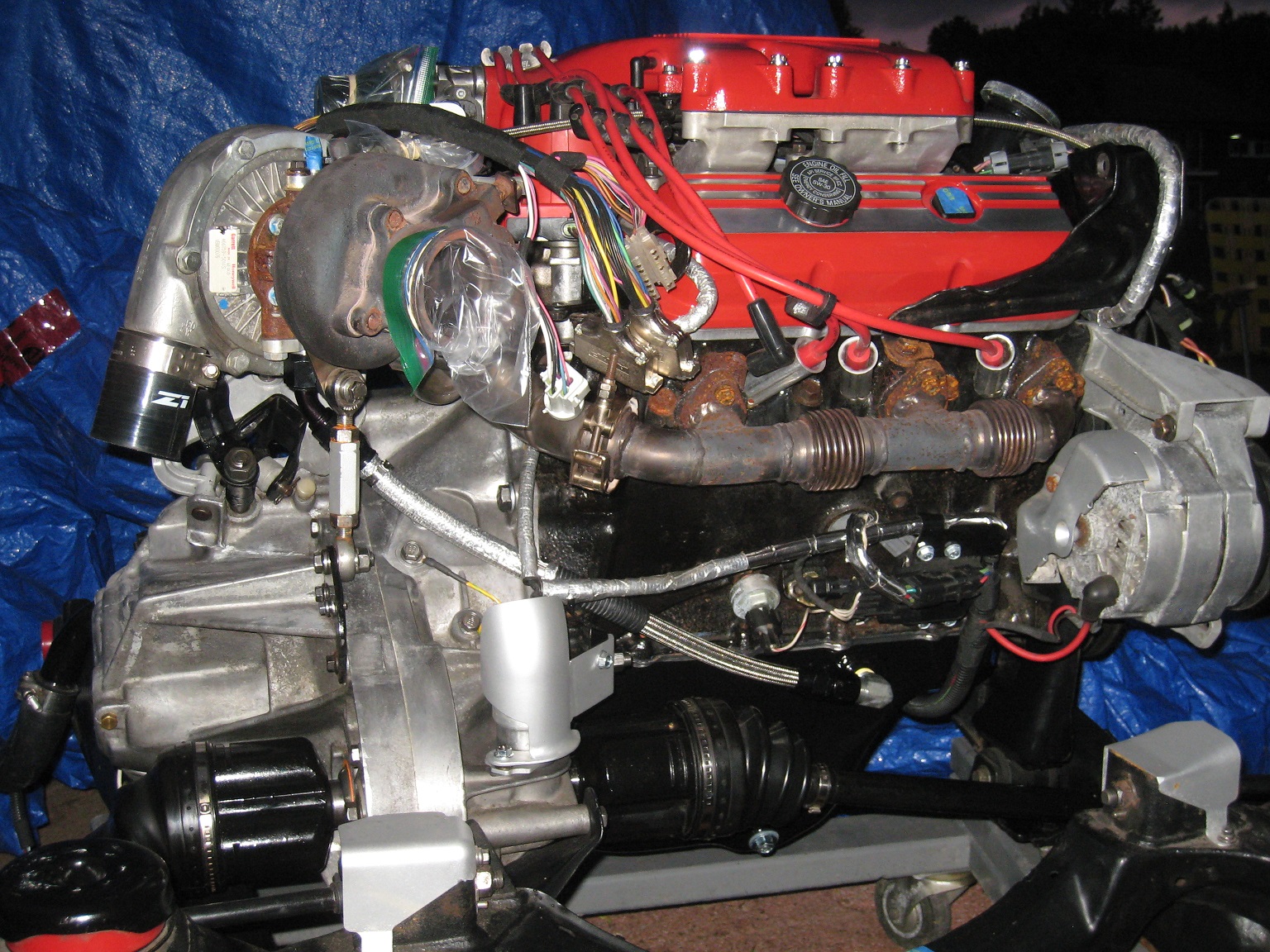
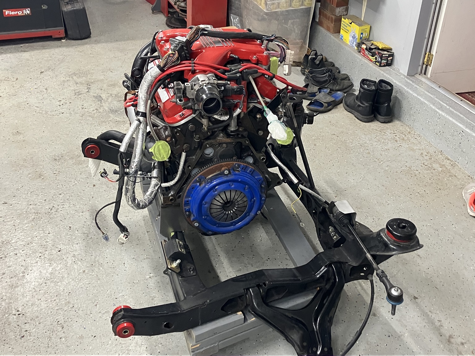
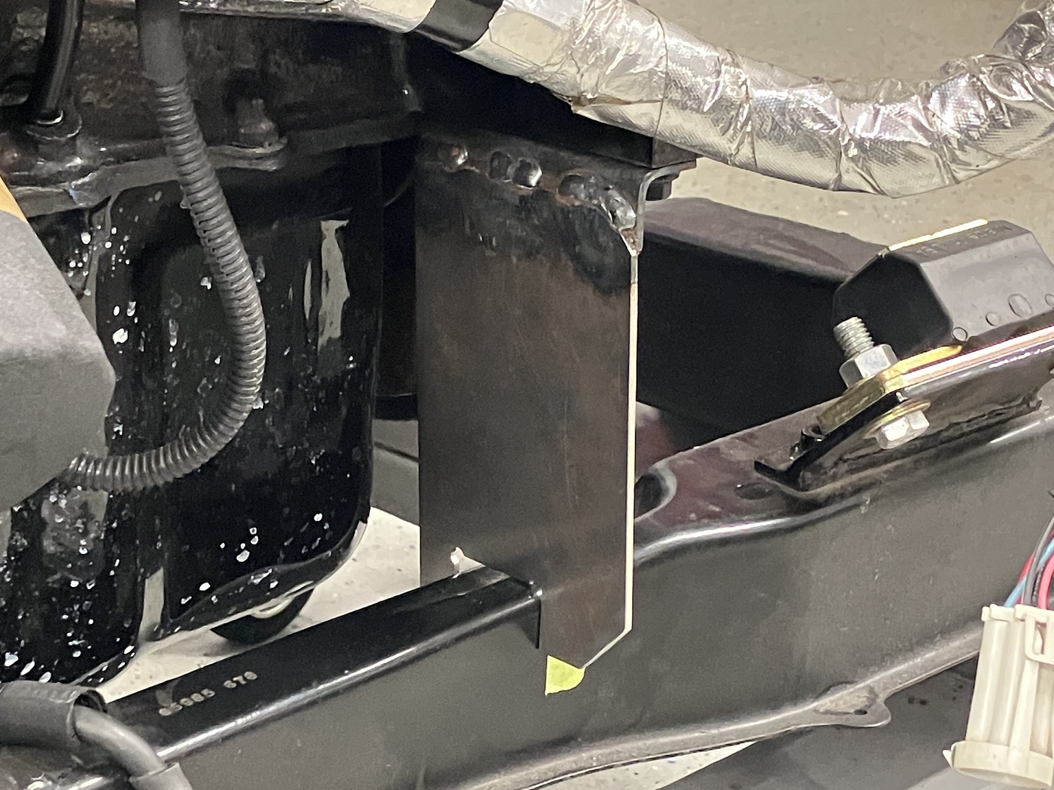
With the Muncie still in place, I installed temporary engine supports, and then I removed the Muncie.
From here, I can bolt the Getrag F23 to the engine, make/modify/fit the transmission mounts, and then finally remove the temporary supports once the transmission mounts are done.
The front temporary support was fairly easy to do. It mounts to the starter's mounting location on the engine block:
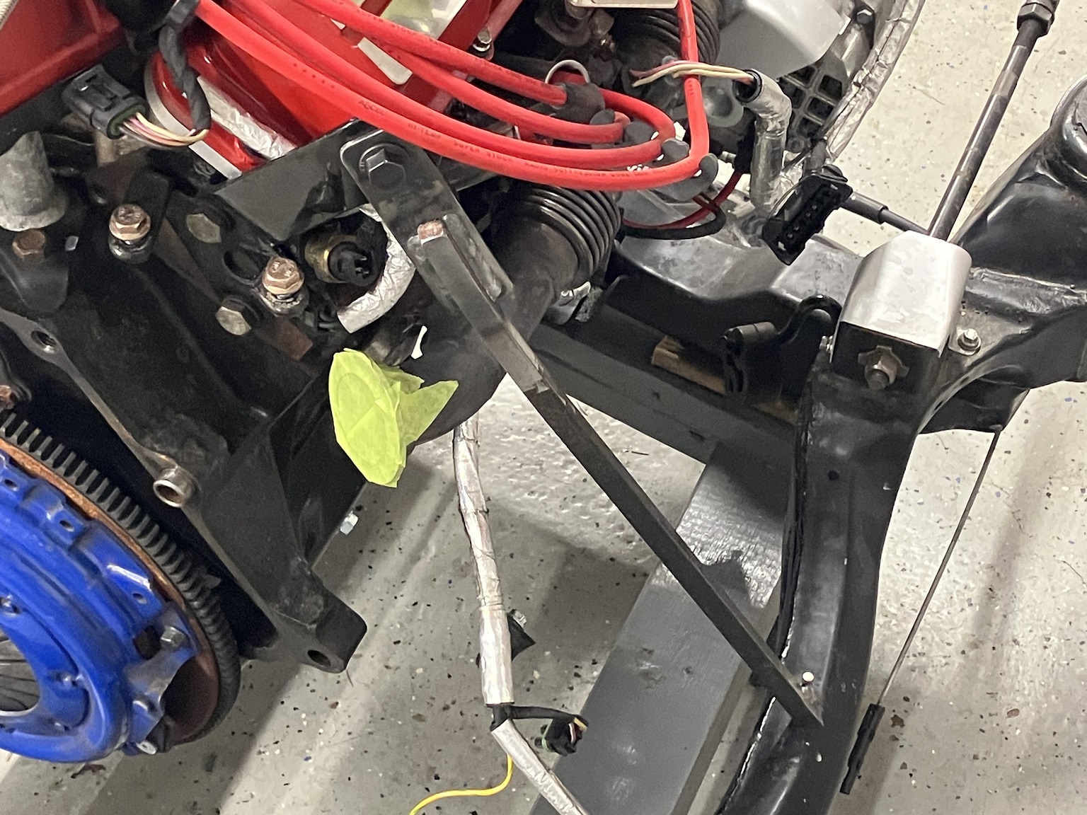
The rear temporary support was a bit more tricky to figure out; it is a long rod going to the rear engine lift hook:
I like the temp supports. when you make your mounts, you may want to add a little bit of preload to account for the weight of the engine and transmission
------------------ "I am not what you so glibly call to be a civilized man. I have broken with society for reasons which I alone am able to appreciate. I am therefore not subject to it's stupid laws, and I ask you to never allude to them in my presence again."
I invited Lou Dias to trash me in my own thread, he refused. sorry. if he trashes your thread going after me. I tried.
It has been a little while since the last update here!
The F23 mated onto my engine, without having to change the clutch, turbo piping, or even the coolant crossover pipe.
The shift linkage was a pain to figure out, as the shifter tower is on the wrong side of the F23 and oriented the wrong way for Fiero use.
I also liked my current turbo setup, and I didn't want to redo everything to install this transmission. This is what I came up with.
The cables will arrive with a fairly direct routing from the firewall, as they did with the stock Muncie setup.
The shift cable is not quite perpendicular with the F23's shifter shaft. It is 7.5° from perpendicular, so shift cable force will have a slight axial component. I installed stiffer centering springs in the F23 to help stay in the 3-4 plane despite the presence of axial force during hard shifts.
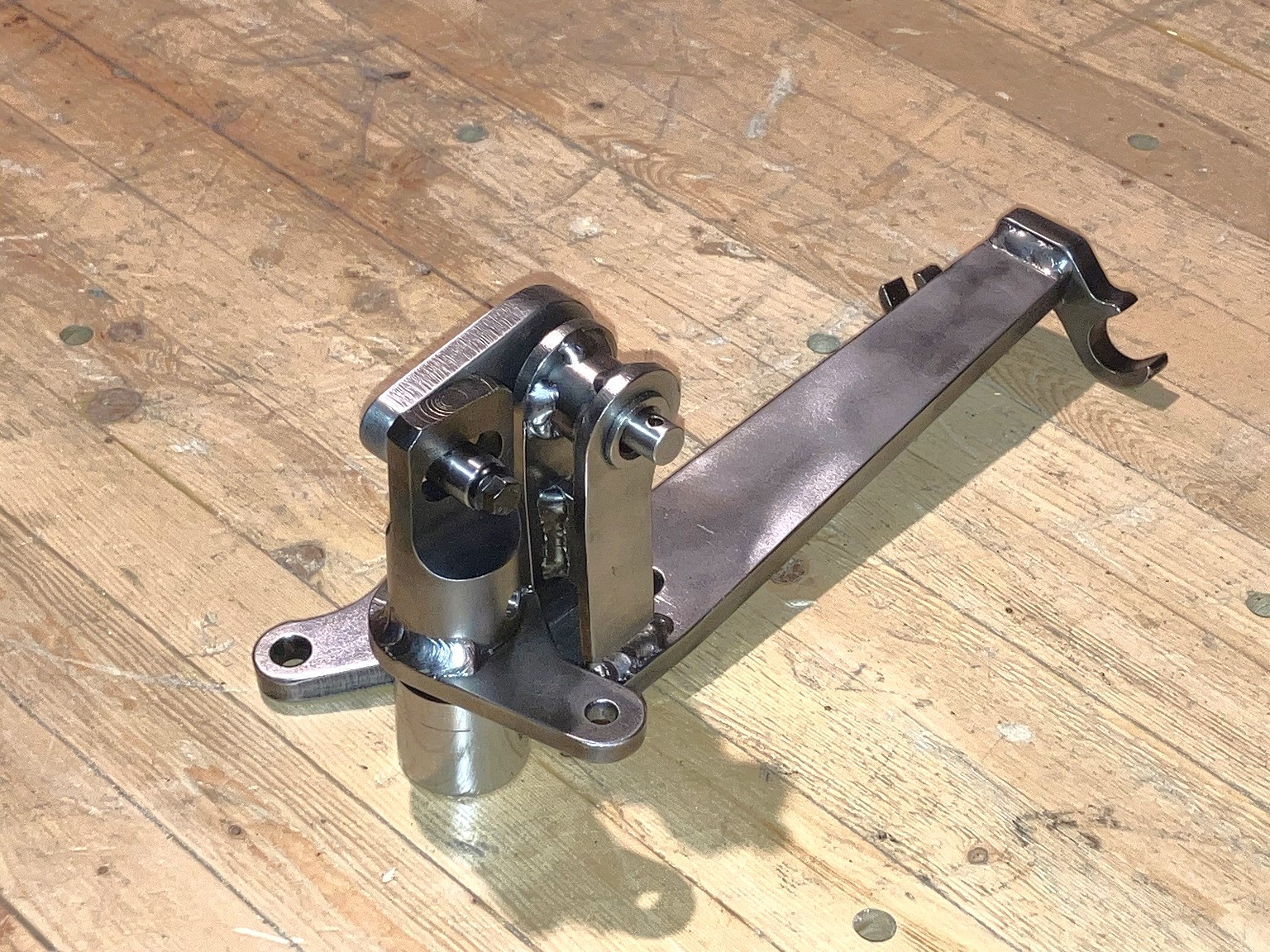
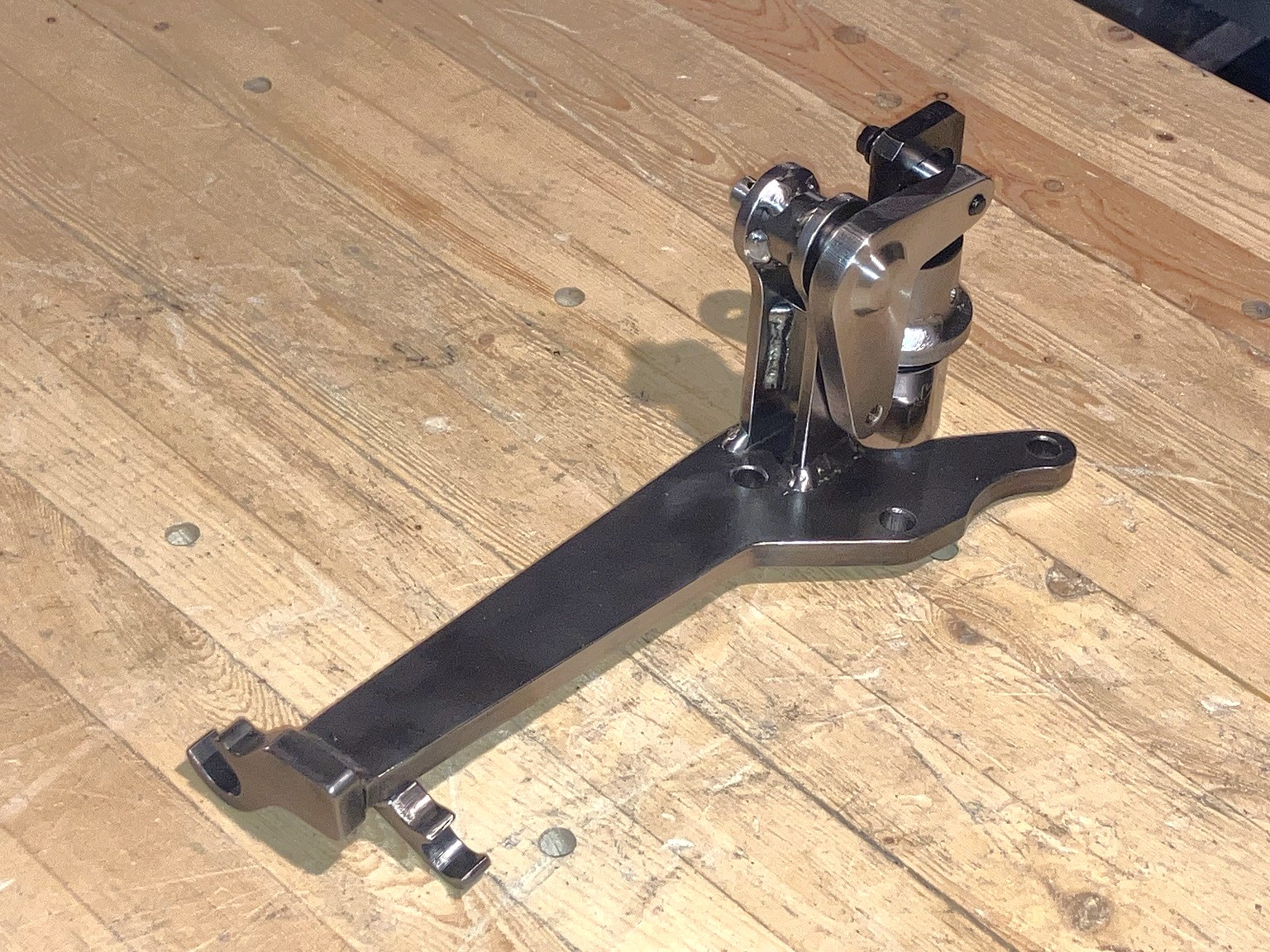
These parts (except for the bellcrank, which is in stainless steel) need to be sandblasted and painted with POR-15.
I designed this shifter (on the transmission) to work with custom Cablecraft cables. Now I need to modify the shifter in the cabin to work with Cablecraft cables.
The edges of the plates needed to be deburred/sanded/wirebrushed as-delivered from sendcutsend because the laser-cutting process doesn't generate fully "nice" parts.
Then, the parts needed to be sanded/wirebrushed to prepare the weld areas for welding (remove mill scale).
After welding, welding spatter and silicon islands had to be scraped off, sanded, wirebrushed...
I assume you're adding a bushing of some kind to the area circled in green?
is there some kind of bearing on the red circled shaft?
------------------ "I am not what you so glibly call to be a civilized man. I have broken with society for reasons which I alone am able to appreciate. I am therefore not subject to it's stupid laws, and I ask you to never allude to them in my presence again."
I invited Lou Dias to trash me in my own thread, he refused. sorry. if he trashes your thread going after me. I tried.
Igus bushings are quite easy to use. They often press in with a small amount of force (my bench vise was more than enough in this case). Inch and metric sizes are available in many different kinds of plastic. We used them regularly at my work in small electric actuators.
In this case, I made the steel tube part with an undersized centre hole, knowing that the welding could distort the hole. After welding, I used a hand reamer to enlarge the hole to the size needed by the Igus bushings.
The pin (red circled area) is just a rod (actually, it was the shank of a Grade 5 bolt) with a hole drilled through it.
I don't think there's much friction there, so a bearing would be overkill.
This is a bit like with (properly designed) valve rocker arms, where there is not much movement between the valve tip and the rocker arm shoe, so a roller there is generally not worth having.
Additionally, my shifter has less sweep there than on a stock F23, because the bellcrank's lever arm is longer than stock F23.
the bushings are very similar to what would have been on the stock F23 shifter, when I built my mechanism, I was able to salvage the stock bushings from an F23 and reuse them, but my shifter also used the stock F23 select arm so using the stock bushings made sense.
I look forward to hearing how everything fits and feels in the car, especially with relation to the centering springs!
------------------ "I am not what you so glibly call to be a civilized man. I have broken with society for reasons which I alone am able to appreciate. I am therefore not subject to it's stupid laws, and I ask you to never allude to them in my presence again."
I invited Lou Dias to trash me in my own thread, he refused. sorry. if he trashes your thread going after me. I tried.