TiAL acknowledged that yes, the BOV will open during overrun.
However, they maintained that positive pressure will be maintained upstream of the throttle body whenever the BOV opens... I guess because the turbo is spinning anytime the engine is running. So normally, dirt should not come in; it should be blown out.
They did suggest that if I was driving in a very dusty/dirty environment, then a conservative approach would be to use their recirculating BOV, either with a small air filter on it, or routed back to the airbox.
I have never given much thought to a BOV ingesting during deceleration not have I seen any talk about it. Most just talk about the springs rates for opening and closing during desired operations. I myself would not be overly concerned about it. I would be most concerned for the BOV working properly during let off so I do not hurt the motor.
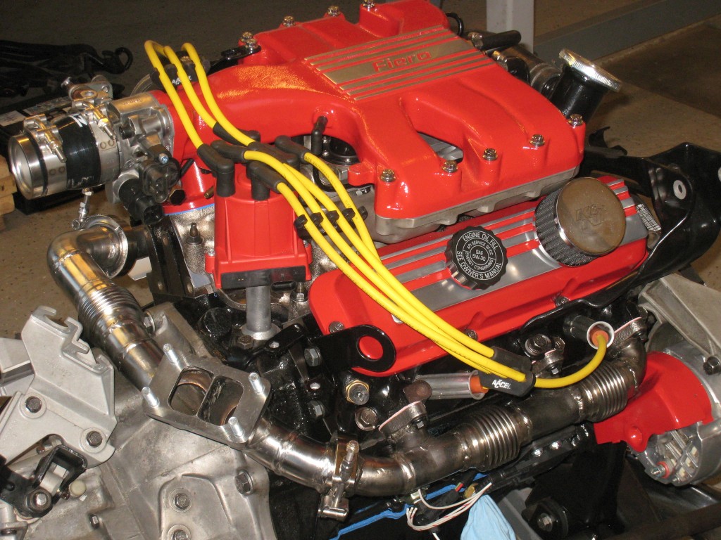
I finished the exhaust up to the turbine inlet. I am using the stock log manifolds, but with bellows in between the ports. With the bellows, each segment of the exhaust can grow independently as they get hot, without developing undue stress. The same reasoning applies to the bellows in the crossover pipe.
The bellows fit underneath the stock front manifold heat shield, provided that I hammered the AC compressor clearance bump flat. Since I don't have AC, no problem there. I'm using the Volkswagen exhaust port gaskets. They have a stainless steel exterior; looks like they won't blow out.
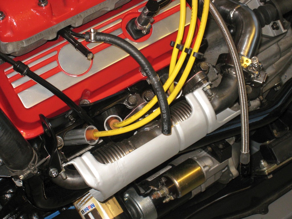
The compressor housing is quite close to the shift cables, but I should still be able to install/uninstall them. I successfully tested this theory with the engine+cradle in the car, as if I were doing it for real. The shift cables come really close to the crossover pipe; I'll have to come up with some sort of heat shield, in addition to the insulating sleeves that come on the Rodney Dickman cables.
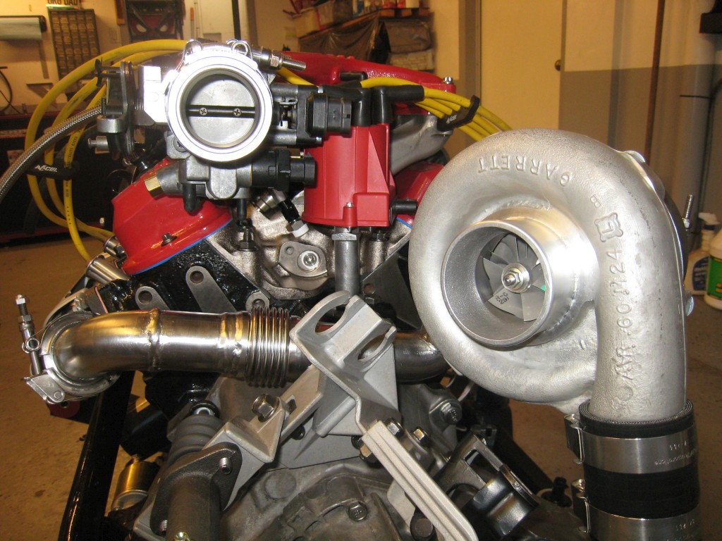
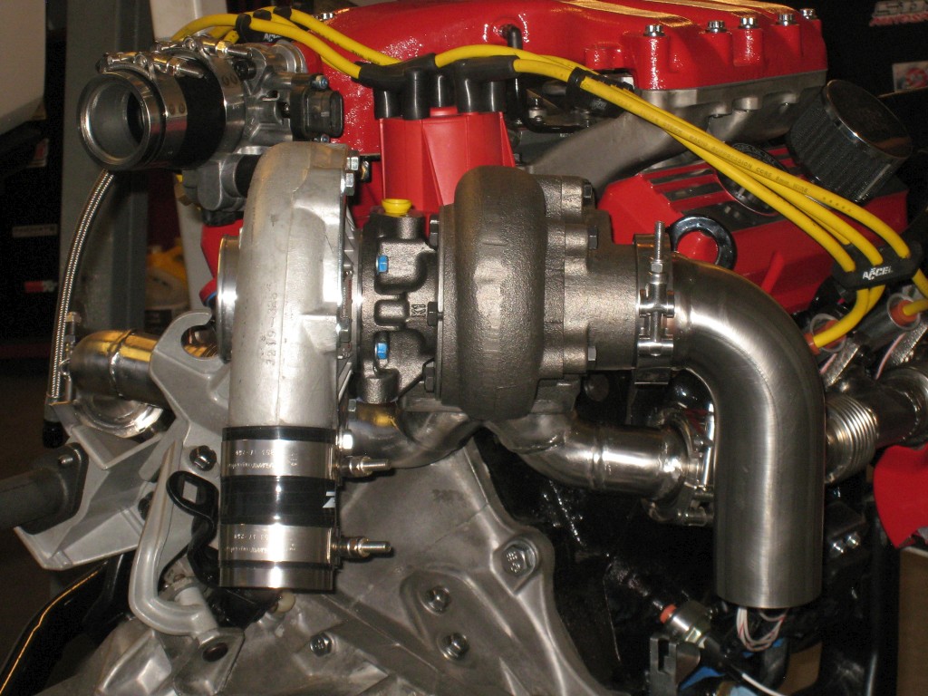
Right now the turbo is supported only by the exhaust. An additional support to hold the turbo's weight is presently in the works.
I finished the exhaust up to the turbine inlet. I am using the stock log manifolds, but with bellows in between the ports. With the bellows, each segment of the exhaust can grow independently as they get hot, without developing undue stress. The same reasoning applies to the bellows in the crossover pipe.
The bellows fit underneath the stock front manifold heat shield, provided that I hammered the AC compressor clearance bump flat. Since I don't have AC, no problem there. I'm using the Volkswagen exhaust port gaskets. They have a stainless steel exterior; looks like they won't blow out.
The compressor housing is quite close to the shift cables, but I should still be able to install/uninstall them. I successfully tested this theory with the engine+cradle in the car, as if I were doing it for real. The shift cables come really close to the crossover pipe; I'll have to come up with some sort of heat shield, in addition to the insulating sleeves that come on the Rodney Dickman cables.
Right now the turbo is supported only by the exhaust. An additional support to hold the turbo's weight is presently in the works.
Hopefully I'll be able to take the car for a spin a few times sometime before it snows, around November. I've done a good amount of the work so far; I see the light at the end of the tunnel.
I try to think a few steps ahead, so that I have the right parts/supplies already on hand when I need them.
I've been thinking about the first startup, and how I should use motor oil with ZDDP or other magical ingredients to reduce the risk of wiping a cam lobe in the first half-hour of life. So far, I have identified Redline-brand oil as a candidate: https://www.redlineoil.com/15w40-diesel-motor-oil I can buy this locally.
It says "WITH EXTRA ZDDP FOR WEAR CONTROL" right on the bottle.
Previously, I used 15W-40 Shell Rotella T in my Fiero, but as time goes on, I'm not even sure if that's good oil anymore.
Very Impressive build, neat, clean and well put together. Your knowledge of automotive electronics is also a cut above the rest. The engine should really run nice.
------------------ " THE BLACK PARALYZER" -87GT 3800SC Series III engine, custom ZZP /Frozen Boost Intercooler setup, 3.4" Pulley, Northstar TB, LS1 MAF, 3" Spintech/Hedman Exhaust, P-log Manifold, Autolite 104's, MSD wires, Custom CAI, 4T65eHD w. custom axles, Champion Radiator, S10 Brake Booster, HP Tuners VCM Suite. "THE COLUSSUS" 87GT - ALL OUT 3.4L Turbocharged engine, Garrett Hybrid Turbo, MSD ign., modified TH125H " ON THE LOOSE WITHOUT THE JUICE "
Originally posted by Dennis LaGrua: Your knowledge of automotive electronics is also a cut above the rest.
I work in the design of automotive electronics, so that may clarify things...
quote
Originally posted by Frenchrafe: PS : Thanks for the tip in using bellows on the exhaust manifold logs - I'll be doing this the next time when mine crack again!
I think it's a good idea, but I'll only know for sure once I have some miles on the car!
[This message has been edited by pmbrunelle (edited 06-29-2019).]
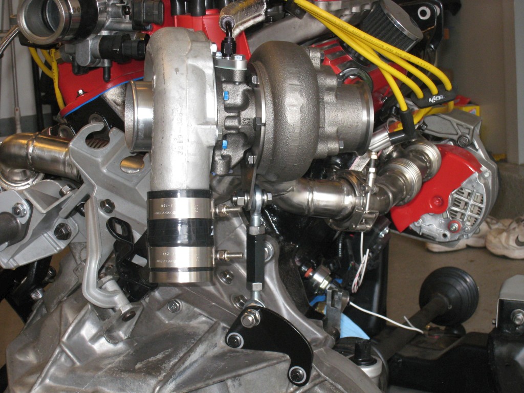
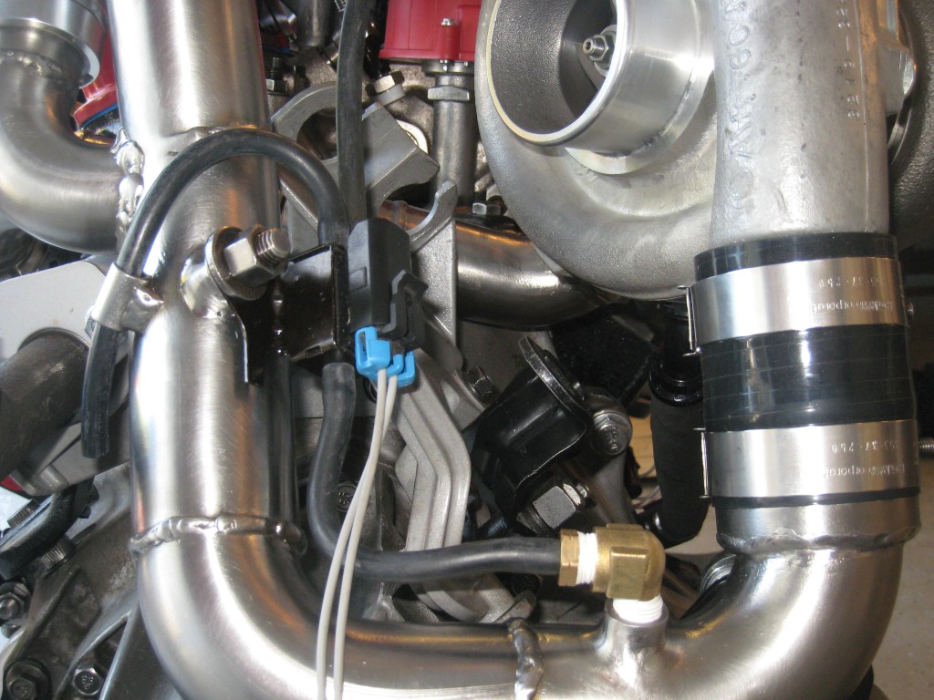
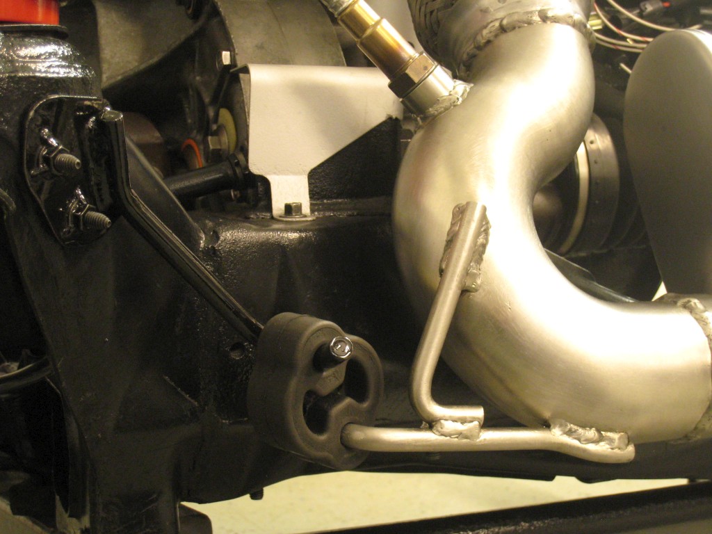
Here the turbo support is installed. Its function is to support the weight of the turbo, to take the weight off the crossover pipe.
I'm using a RH-LH pair of 7/16"-20 rod ends threaded into a hex rod. Since the crossover pipe sags by 0.008" under the weight of the turbo, I simply crank up the rod-end assembly to raise the turbo's position by 0.008". The idea is to put the crossover pipe into its "zero-stress" position.
I was inspired by seeing many 80s turbo Formula 1 engines having this kind of setup.
Most of the steel plates I'm cutting with a hacksaw, angle grinder + cutoff wheel, drill press for internal corners. Bench grinder and files for the last bits of material removal.
Either I'm making 1:1 paper/cardboard models, and tracing the result on the steel, or I'm drawing lines directly on the steel with a ruler, compass, etc.
Only for the more "precision" work, or for shapes that would be a PITA to do with hand tools, then I make a *.dxf drawing, which I have cut by a metal shop in my town. They have a plasma-cutting table.
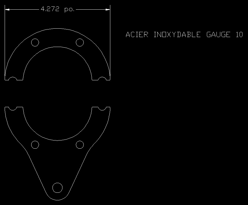
If we look at the turbo support components, the turbine housing clamping plates were something I outsourced. I made this *.dxf and had it cut from stainless:
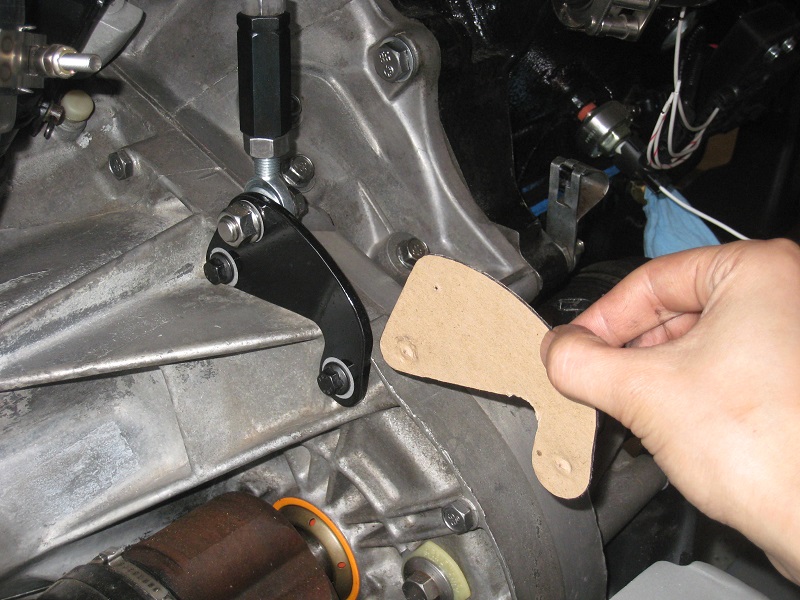
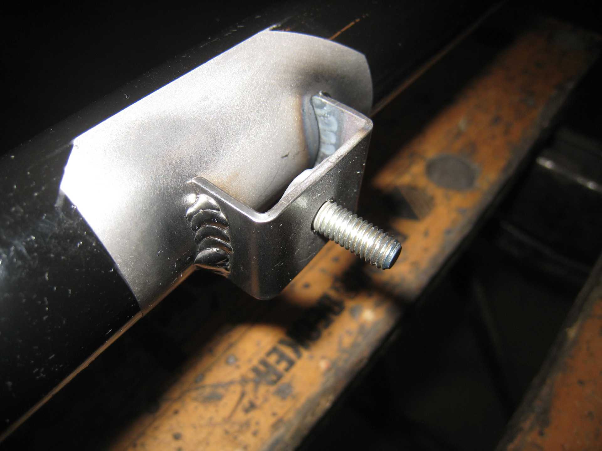
On the other hand, the bottom mount that bolts to the transaxle was easily within my capabilities. I did the design in cardboard, traced it in steel, and then cut it out:
It was just faster and easier to DIY it. I sidestepped the difficulty of digitizing a semi-arbitrary shape (as opposed to something easy to measure, such as a circle or rectangle). Outsourcing also brings the administrative burden of having to keep tabs on the supplier.
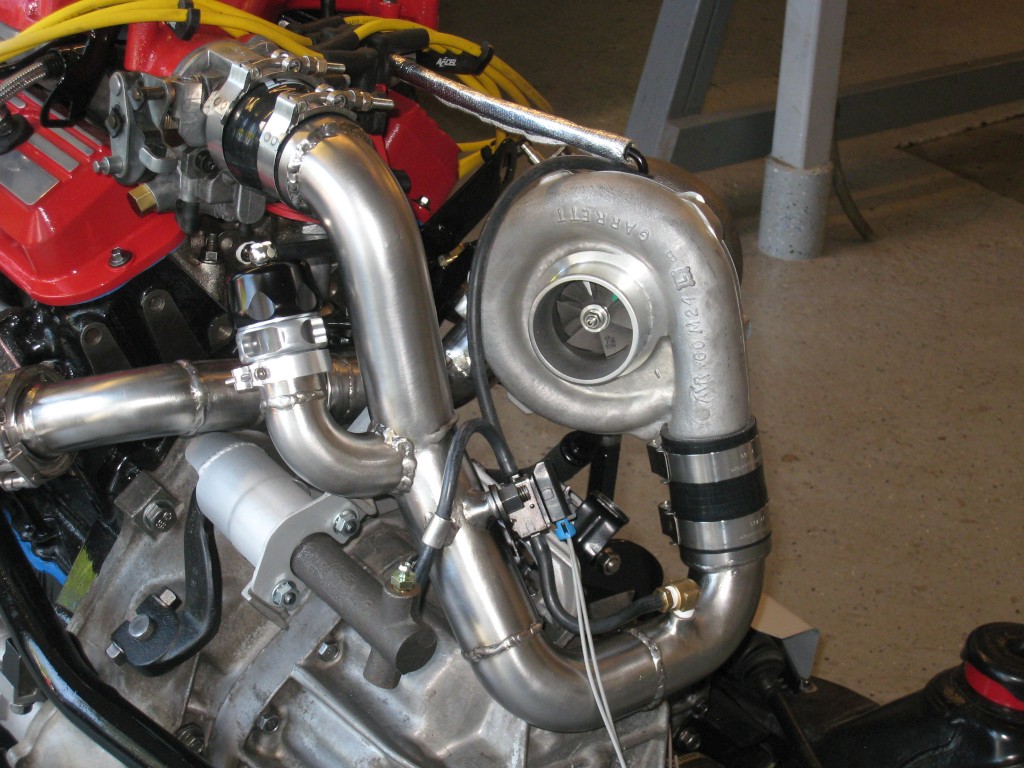
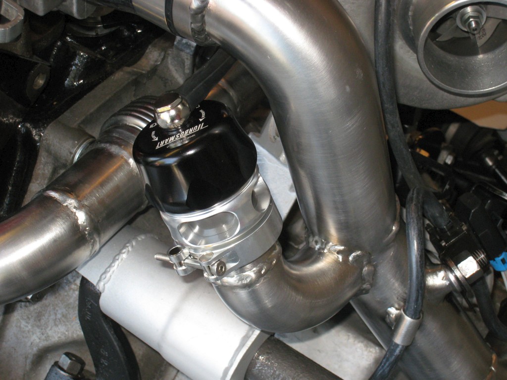
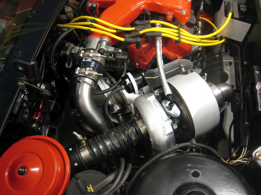
I finished the air pipe linking the turbo's compressor outlet to the throttle body:
I ended up going with the Turbosmart Vee Port Pro BOV. It's rated to be capable of venting 600 hp of compressed air, whereas the TiAL Q is rated at 1800 hp... which is overkill for my Fiero. The Turbosmart unit is physically smaller than the TiAL piece, hence I decided to go with the more compact, easier-to-package solution:
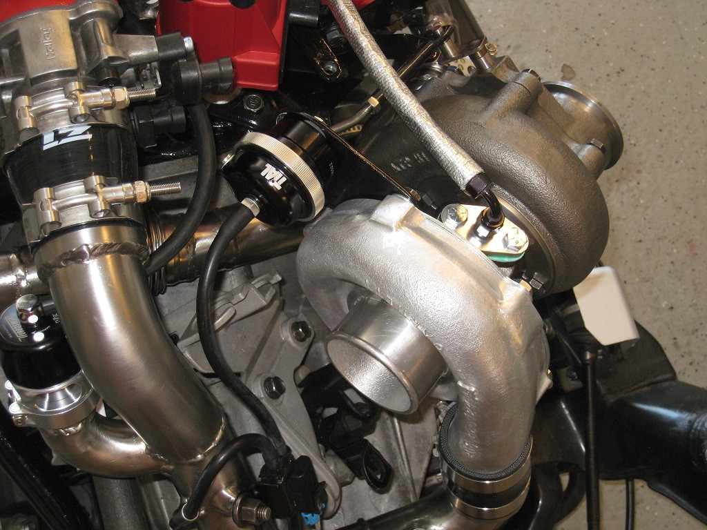
Here is the GM 3-port boost control solenoid (used on the Syclone/Typhoon). This will be computer-controlled, allowing the computer to increase the boost pressure beyond the wastegate spring setting:
I own the red and green springs, which should provide enough flexibility for me. I expect to fine-tune the boost pressure with the electronic solenoid, rather than by spring selection.
I got the bent-rod version of the actuator, so that it would clear the compressor housing.
Did this Fiero have any Kentucky owner history? It looks so much like my first Fiero, a 1986 white/black notchie with the same interior colors, and 2.5 "Iron Duke". The Kentucky buyer called me about an hour after driving away . . "How do I get this gas filler cap cover open?"
It's definitely not your old Fiero. Mine has the (Canadian market) Z49 RPO code, and it still had an Ontarian car dealer sticker on the decklid when I took possession; seems like it spent its life in Canada. Additionally, mine is a 1985, and came with the 2.8 V6.
When I bought my first Fiero, I too struggled at the gas station with trying to find the filler cap release!
White bumperpad notchies were one of the most commonly produced Fiero body styles.
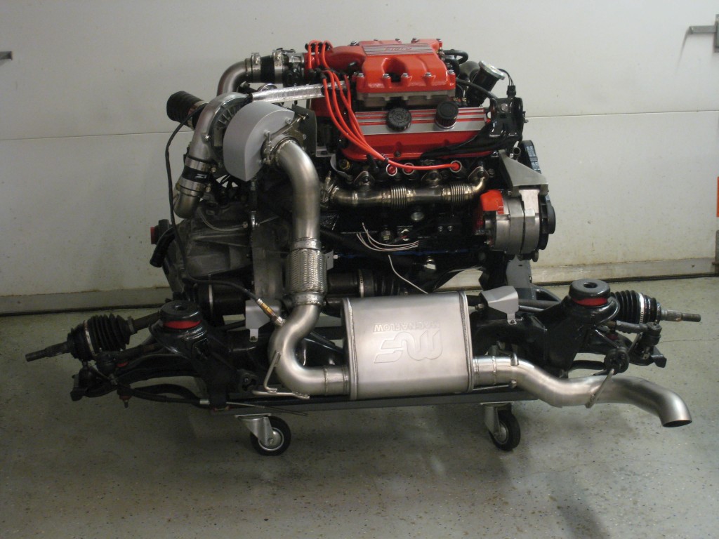
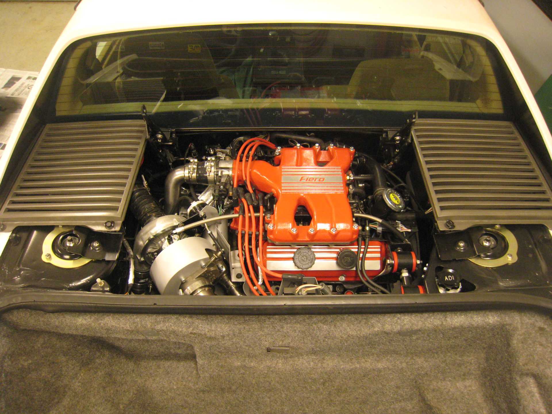
The powertrain is in the car (for the moment), and everything seems to fit.
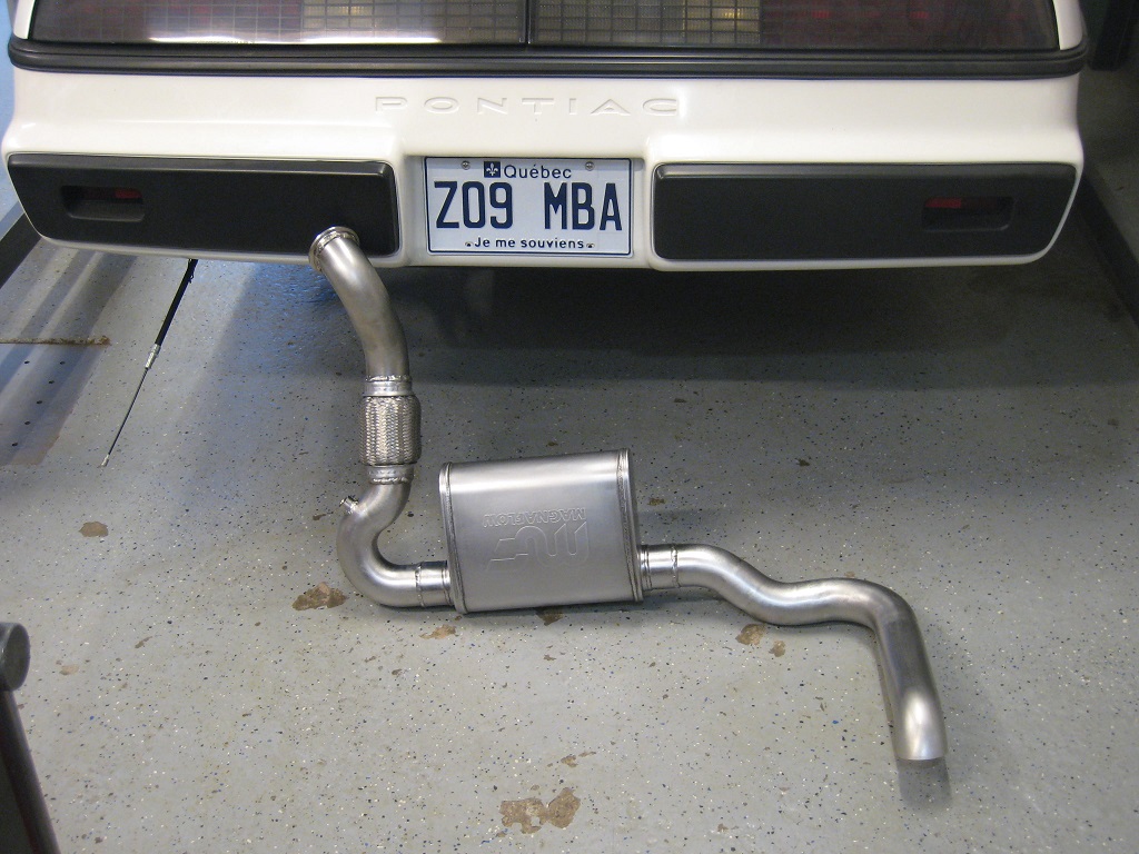
The main steps remaining before driving the car are to fabricate the exhaust piping from the turbine outlet all the way to the exit, and lastly tweaking the wiring harness as needed.
The bender is rated for bending up to 3/8" round steel rod. 3/8" round is really at the tool's limit. I used a cheater bar on the handle to get the job done.
The engine wiring harness is complete, except for 5 wires that lead to future gauges up front. I have three Speedhut gauges that I'll be mounting in the rally gauge pod. They aren't strictly necessary for the engine's operation, so I may start driving the car before finishing up the gauges.
The wiring took about 4 months to do; way longer than I had expected.
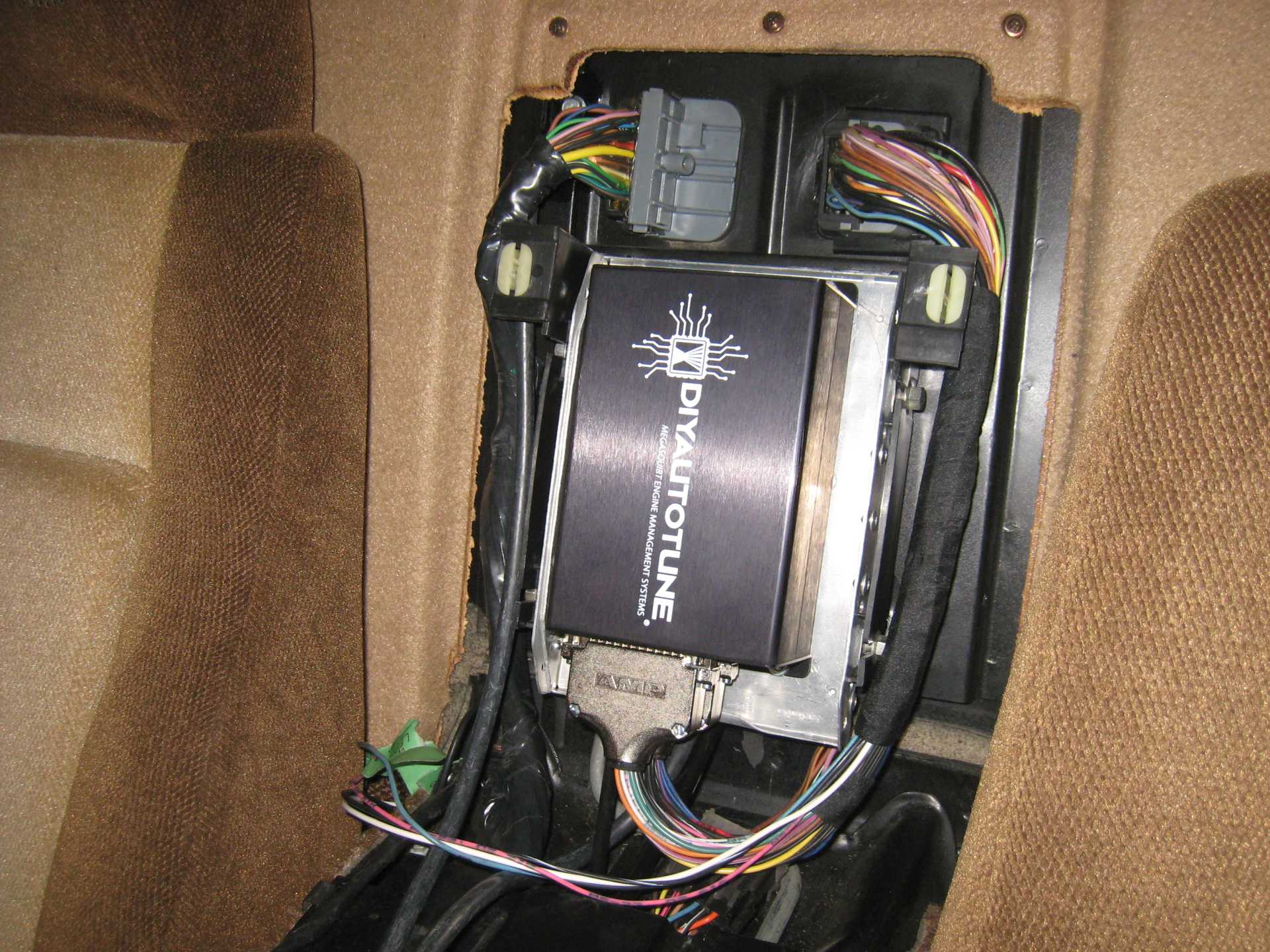
Here is the MegaSquirt 3 computer:
Unlike its predecessor (MS2), this computer has two DB-37 connectors. My particular setup uses 44 of the 74 total pins.
Before covering up the harness with split loom and tape, I tested as many circuits as I could without actually running the engine. Any electrical problems would be easier to solve with the harness still just bundled together with tie-wraps. No problems were found.
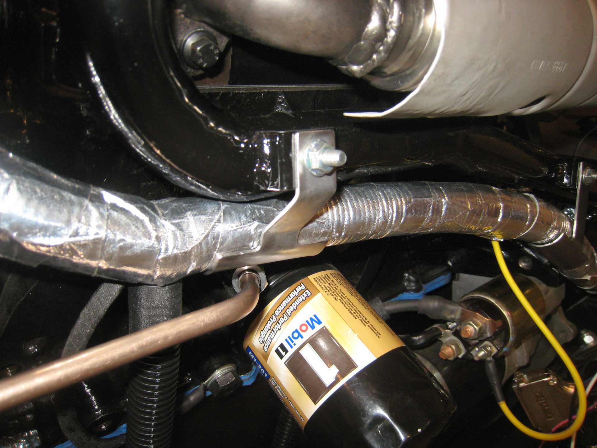
I made some brackets to support the harness in various locations. This is how the harness is supported by the engine coolant tube:
I thought it was important to keep the weight of the harness off the turbo oil supply line which runs underneath:
After painting the "half-pipe" brackets with POR-15 black, I taped the harness to the brackets.
in reference to your water injection, are you worried at all about heat soak reducing the effectiveness?
------------------ "I am not what you so glibly call to be a civilized man. I have broken with society for reasons which I alone am able to appreciate. I am therefore not subject to it's stupid laws, and I ask you to never allude to them in my presence again."
Most of the water won't get hot, since it's away from the engine heat in the tank. However, there is the "dead-end" of stagnant water in the IAC passage that could become heat-soaked if I just cruise around without ever entering boost.
A worst-case scenario would be that the engine heat causes the water in the IAC passage to completely evaporate, leaving the IAC passage empty. Then, when I hit boost, the engine will be without water for a half-second or so; the IAC passage must first be filled with water before the nozzles can spray.
The check valve springs in the nozzles *should* keep the water in the IAC passage pressurized to at least 35 psia; I think the pressure will raise the boiling point of the water enough to prevent boiling. I'm sure you know about this from your experience on steam-powered boats.
As a last resort, I could implement a software patch to trickle some small amount of water into the engine every X minutes (even out of boost), so the hot water in the IAC passage gets slowly replaced with fresh cool water. This is possible because the MegaSquirt source code is made available so end-users can customize their software; I can't imagine having a modded car with a closed-source ECU.
So what's the difference between injecting hot vs. cold liquid water into the engine?
Well liquid water droplets are sprayed from the nozzles, and liquid water is sucked into the cylinder during the intake stroke.
During the compression stroke (or maybe start of power stroke?), the temperature will increase to a point that the liquid water will boil into steam. As the liquid water boils into steam, the water will absorb heat energy from its surroundings equal to its latent heat of vaporisation. The heat of vaporisation is much more than the difference between hot vs. cold liquid water, so I don't think there would be much difference in terms of cooling the contents of the cylinder.
Of course, this analysis was supposing that the anti-detonant effect of water is due to cooling. However, we know that anti-detonant effects are possible due to other (chemical?) reasons... as we see with the addition of tetraethyl lead to fuel.
Maybe water has an anti-detonant effect due to some mechanism other than cooling; I don't know.
An interesting test would be to run the engine with chilled dry air; cold enough so that the in-cylinder temperature is the same as with water injection. If the results are the same, then we conclude that water injection works by the cooling effect. If the results are different, despite the same temperatures, then we conclude that the water molecules have some other anti-detonant effect.
[This message has been edited by pmbrunelle (edited 03-29-2020).]
Most of the water won't get hot, since it's away from the engine heat in the tank. However, there is the "dead-end" of stagnant water in the IAC passage that could become heat-soaked if I just cruise around without ever entering boost.
A worst-case scenario would be that the engine heat causes the water in the IAC passage to completely evaporate, leaving the IAC passage empty. Then, when I hit boost, the engine will be without water for a half-second or so; the IAC passage must first be filled with water before the nozzles can spray.
The check valve springs in the nozzles *should* keep the water in the IAC passage pressurized to at least 35 psia; I think the pressure will raise the boiling point of the water enough to prevent boiling. I'm sure you know about this from your experience on steam-powered boats.
As a last resort, I could implement a software patch to trickle some small amount of water into the engine every X minutes (even out of boost), so the hot water in the IAC passage gets slowly replaced with fresh cool water. This is possible because the MegaSquirt source code is made available so end-users can customize their software; I can't imagine having a modded car with a closed-source ECU.
So what's the difference between injecting hot vs. cold liquid water into the engine?
Well liquid water droplets are sprayed from the nozzles, and liquid water is sucked into the cylinder during the intake stroke.
During the compression stroke (or maybe start of power stroke?), the temperature will increase to a point that the liquid water will boil into steam. As the liquid water boils into steam, the water will absorb heat energy from its surroundings equal to its latent heat of vaporisation. The heat of vaporisation is much more than the difference between hot vs. cold liquid water, so I don't think there would be much difference in terms of cooling the contents of the cylinder.
Of course, this analysis was supposing that the anti-detonant effect of water is due to cooling. However, we know that anti-detonant effects are possible due to other (chemical?) reasons... as we see with the addition of tetraethyl lead to fuel.
Maybe water has an anti-detonant effect due to some mechanism other than cooling; I don't know.
An interesting test would be to run the engine with chilled dry air; cold enough so that the in-cylinder temperature is the same as with water injection. If the results are the same, then we conclude that water injection works by the cooling effect. If the results are different, despite the same temperatures, then we conclude that the water molecules have some other anti-detonant effect.
boiling wasn't the big concern, but you are right about latent heat, it is a very significant amount of energy, without any change in temperature. I know it's been in use since the 1930's at least, in fighter planes (I almost said jets... lol!) it would be an interesting test to see, but probably a fairly difficult one to accomplish. I'm considering water/meth for my car until I can find or build a suitable a2w intercooler for my configuration.
My only other concern I would have, would be valve failure, if the check valve in one of the nozzles fails, there will be almost no way to detect it except for changes in performance. It may be worthwhile to plumb a pressure transducer to the IAC passage so that you have that indication available, if you have another available analog input on the MS3x
The MS stuff is awesome, unfortunately for me, I know almost nothing about computer code, so I can't make as much use of it as others can.
------------------ "I am not what you so glibly call to be a civilized man. I have broken with society for reasons which I alone am able to appreciate. I am therefore not subject to it's stupid laws, and I ask you to never allude to them in my presence again."
Absolutely amazing build. Glad to have met you about this time last year. i could tell by the way you talked that you must be some kind of automotive engineer. This stuff is way over my head. You're going to enjoy your car. jon
------------------ Astronomy says we will find a coded signal from outer space. Then we'll KNOW that life exists there, for coded signals aren't by chance.
Biology says there are coded genetic signals in every cell, but we KNOW that no intelligence created life.
I'm the original owner of a white ' 84 2M4 purchased Dec 10, 1983 from Pontiac. Always garaged, no rust, 4-wheel drifts are fun!
Originally posted by ericjon262: My only other concern I would have, would be valve failure, if the check valve in one of the nozzles fails, there will be almost no way to detect it except for changes in performance. It may be worthwhile to plumb a pressure transducer to the IAC passage so that you have that indication available, if you have another available analog input on the MS3x
To detect if the water in the IAC passage boiled off due to check valve failure, I could do a test at idle: 1. Open the water solenoid. 2. See how long it takes for the engine to cough and stumble. 3. If the engine stumbles right after opening the solenoid valve, then the IAC passage is full of water. 4. If there's a time delay between opening the solenoid and the stumble, that means the IAC passage was empty.
But yes, in general, I'm putting a lot of faith in an assembly that I can't easily inspect. The water manifold / nozzles are perhaps the most risky part of this Fiero project.
Nevertheless, I enjoy the risk and uncertainty... that's what makes the project interesting and challenging. I didn't want to follow a well-proven recipe.
I'll probably pull the intake in a year or two to check the nozzle spray patterns... could be earlier if I blow up the engine.
quote
Originally posted by ericjon262: The MS stuff is awesome, unfortunately for me, I know almost nothing about computer code, so I can't make as much use of it as others can.
I remember that once upon a time, you were welding with a flux core unit. Now you have graduated to TIG. You improved your skills/knowledge, in conjunction with your personal projects. Similarly, if you want to add basic programming to your skill set, your MS is there and ready for you...
The MS3 code probably has around 100 kloc (kilolines of code) for the entire project... obviously a beginner shouldn't attempt to rewrite an entire engine management software on his own. However, with beginner-level programming skills, you can make meaningful changes with 100 loc modifications, or even 10 loc.
Absolutely amazing build. Glad to have met you about this time last year. i could tell by the way you talked that you must be some kind of automotive engineer. This stuff is way over my head. You're going to enjoy your car. jon
I'm glad I met you too... now when we correspond online, we know the face behind the keyboard.
As far as my automotive job goes... I still have it for the moment, but the economic situation is delicate. I may be forced to transition over to some other field...
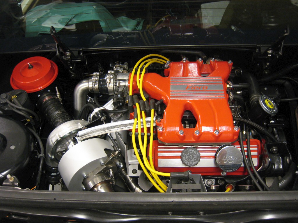
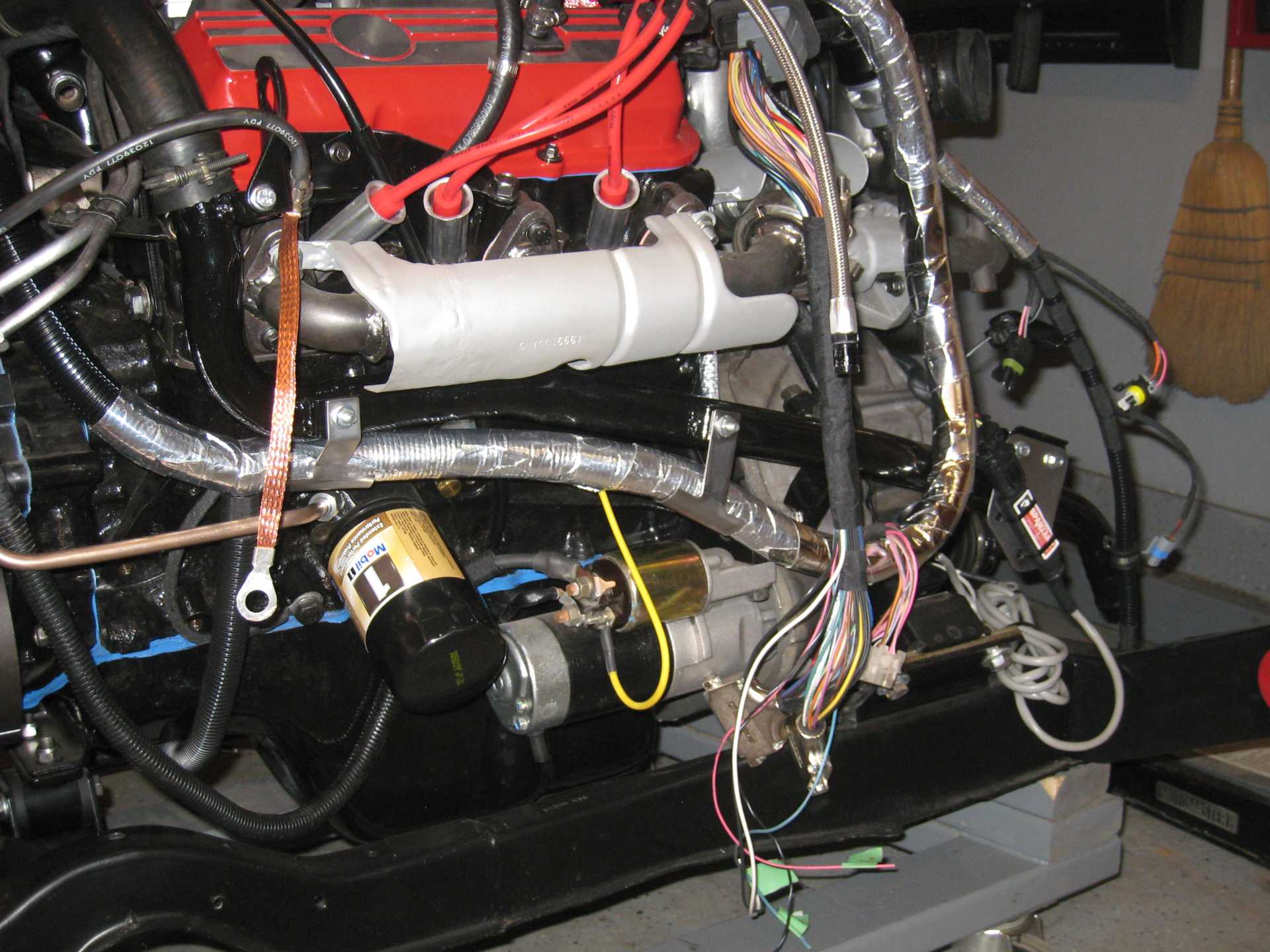
The powertrain is in the engine bay, for real now:
I just need to fix up the brakes (they were rusty, leaking fluid, and the parking brake didn't work) before starting the engine for the first time and driving the car.
I may or may not install the decklid for the first start. I'm thinking that no decklid would enhance access to the engine bay if I need to deal with an engine bay fire, for instance.
I don't even remember my last time running flux core! LOL. I could definitely learn it, right now, I don't feel like I have the time to devote to it, I have lots of engineering projects I'm working on, and adding coding to the list would ensure that none of them get done!
I wasn't necessarily meaning the water boiling off, more just leaking into the intake, that being said, only a small amount could leak from the manifold, and it's probably not enough to matter anyways.
Man, that engine looks good in there. I really like the effort you put into making the whole assembly appear to be a stock unit, if someone didn't know a Fiero didn't come stock like that, they would assume it did.
------------------ "I am not what you so glibly call to be a civilized man. I have broken with society for reasons which I alone am able to appreciate. I am therefore not subject to it's stupid laws, and I ask you to never allude to them in my presence again."
There was a bit of farting around with getting the engine to actually start; I believe this was due to the ECU not being tuned whatsoever for this engine.
Once the engine caught, I brought it up to 2000~2500 RPM. I used my laptop computer to adjust the AFR to about 14 so that the engine could smoothly complete the 1/2 hour break-in period for the flat-tappet camshaft.
No funny noises, no leaks, no smoke beyond the initial burning-off of paint and oil. I noticed that the exhaust components changed colour. The exhaust pipe coming out of the turbine outlet took on a straw colour.
For a first drive, I find it went well: The transmission and clutch work like they're supposed to. Exhaust noise is a bit loud, but it's within the range of a tuner car. However, it's not a terribly pleasing sound. The engine saw a bit of boost: I briefly hit 125 kPa absolute of manifold pressure (says my dad who was riding shotgun with the laptop)
Some issues were uncovered: The engine seems to run a bit hot; this could be related to the low compression ratio. I might need to get a fancy 3-row radiator. ECU loses synchronization with the crankshaft above ~3000 RPM. Not sure if it's a hardware or software problem.
Overall, I'm quite happy with how things went today.
Of course, before this can become a reliable driver, I still have a bunch more work to do
I'll be sure to give updates as this engine grows up!
This evening, with a warmed-up engine, I focused on getting the car driveable in the idle to 3000 RPM range, for calm neighborhood driving. Learning to crawl before ripping through the gears.
Some observations:
This engine needs a lot more idle airflow than a stock 2.8; I'll need to adjust the idle screw on the throttle body to give the engine the air it needs.
While cruising around in the 10-25 mph range, in 1st, 2nd, or 3rd gear with the throttle barely pressed, the engine would start bucking, oscillating in unison with the windup/backlash of the drivetrain. Making sure the fuel tables were smooth and setting the AFR to 12.5 suppressed the bucking tendency to an acceptable level. For now, I'm OK with that. Later on when the rest of the tune is sorted out, I'll look into leaning out this low-speed cruise.
[This message has been edited by pmbrunelle (edited 04-28-2020).]
glad to see it moving! it sounds nice in the video too, a little quiet, but nice nonetheless.
------------------ "I am not what you so glibly call to be a civilized man. I have broken with society for reasons which I alone am able to appreciate. I am therefore not subject to it's stupid laws, and I ask you to never allude to them in my presence again."
I'll be sure to give updates as this engine grows up!
This evening, with a warmed-up engine, I focused on getting the car driveable in the idle to 3000 RPM range, for calm neighborhood driving. Learning to crawl before ripping through the gears.
Some observations:
This engine needs a lot more idle airflow than a stock 2.8; I'll need to adjust the idle screw on the throttle body to give the engine the air it needs.
While cruising around in the 10-25 mph range, in 1st, 2nd, or 3rd gear with the throttle barely pressed, the engine would start bucking, oscillating in unison with the windup/backlash of the drivetrain. Making sure the fuel tables were smooth and setting the AFR to 12.5 suppressed the bucking tendency to an acceptable level. For now, I'm OK with that. Later on when the rest of the tune is sorted out, I'll look into leaning out this low-speed cruise.
Try to lower your timing to the distributor for your RPM from 500 to 2000 RPM at your map table: KPA / RPM from 20 to 35 KPA
This engine needs a lot more idle airflow than a stock 2.8; I'll need to adjust the idle screw on the throttle body to give the engine the air it needs.
You went from a 3.0" to a 3.31" stroke. That change in stroke also changed your rod ratio or rod angularity. The result is increased piston speed and more swept volume which gives the engine more lungs.
You went from a 3.0" to a 3.31" stroke. That change in stroke also changed your rod ratio or rod angularity. The result is increased piston speed and more swept volume which gives the engine more lungs.
Patrick isn't running a stock ECU, he has an MS3, so he needs to build a base tune more or less from scratch.
------------------ "I am not what you so glibly call to be a civilized man. I have broken with society for reasons which I alone am able to appreciate. I am therefore not subject to it's stupid laws, and I ask you to never allude to them in my presence again."
You went from a 3.0" to a 3.31" stroke. That change in stroke also changed your rod ratio or rod angularity. The result is increased piston speed and more swept volume which gives the engine more lungs.
I think what he was noting is that he has compensated for the change in displacement in the basic engine data in his ECU--the engine would not have started otherwise--but that there's also the mechanical adjustment for base idle airflow on the throttle body, and he hasn't updated that yet.
Patrick isn't running a stock ECU, he has an MS3, so he needs to build a base tune more or less from scratch.
So do I, and he doesnt have to build it from scratch. In the MS when you enter your engine parameters it calculates fueling tables for you. He should have let the "Autotune" feature do the tuning for him while driving and then he can go back and smooth everything out. The one thing that the MS will not calculate is the timing table.It does save a lot of time.
glad to see it moving! it sounds nice in the video too, a little quiet, but nice nonetheless.
Volume is difficult to convey in a video. However, I do have an SPL meter with A-weighting.
We could make up a PFF-standard test procedure, since the standard test procedures (i.e. SAE, ISO) are hidden behind paywalls.
quote
Originally posted by claude dalpe: Try to lower your timing to the distributor for your RPM from 500 to 2000 RPM at your map table: KPA / RPM from 20 to 35 KPA
I have changed my timing table, but I did not have much opportunity to test it. The most important problem to solve now is with the crankshaft sensor malfunction at 3000 RPM.
quote
Originally posted by La fiera: So do I, and he doesnt have to build it from scratch. In the MS when you enter your engine parameters it calculates fueling tables for you. He should have let the "Autotune" feature do the tuning for him while driving and then he can go back and smooth everything out. The one thing that the MS will not calculate is the timing table.It does save a lot of time.
I use the autotune feature for the VE table, but there are still many other settings that need to be adjusted!
is your crank position wire shielded? the position signal wire is supposed to be shielded according to the MS manuals, so that may be something to look at. I use Tefzel sheilded wire from Prowire for all of my CKP and CMP circuits.
------------------ "I am not what you so glibly call to be a civilized man. I have broken with society for reasons which I alone am able to appreciate. I am therefore not subject to it's stupid laws, and I ask you to never allude to them in my presence again."
From the converter box to the MS I have normal untwisted unshielded wires. Since this run carries a low-impedance digital signal, I didn't think it needed any particular attention.
On various forums, the Maxim MAX9924 was all the rage. People said that it just works with no fuss (more reliably than the MS VR input), so I decided to try it.
At 3000 RPM, MS occasionally stops seeing the double-notch on the 7x reluctor wheel (it sees a single-notch instead).
Now I have to play Where's Waldo to find where along the signal chain the double-notch disappears, by probing at different points with my oscilloscope.
The double-notch worked when I cranked the engine at 200 RPM... in hindsight that was not a sufficient test.
On the plus side, the cam sensor seems to work properly.