Originally posted by ericjon262: I've been looking at getting a 12" and 24" dial caliper. I've recently fallen in love with dial calipers compared to digital, something about being able to watch the needle move as I move the caliper is very satisfying,
My dad's goto caliper that he keeps at his desk is a 6" dial Mitutoyo. In my first summer job, I always went to my dad's desk to borrow his dial caliper whenever I wanted to measure something. So I got the taste for dial calipers as a teenager. When I finished school, I got a 150 mm dial Mitutoyo (copycat) for work. I got mine in metric because the automotive world is mostly metric.
With a dial, you can more easily see the needle deflect depending on how you squeeze the part than with digital. You can interpolate between the graduations. Dial has the advantage of not running out of battery and starting to blink; it's always ready to go. In a workplace with many people, the dial caliper never goes missing; nobody else wants to borrow it.
I would say that unit conversion is inconvenient; if I was going to work with mixed inch/mm units, then the digital caliper makes more sense as you can switch it over by pressing a button.
At home I have a cheap digital caliper, and I'm having to change the battery every few months. Probably a name-brand such as Mitutoyo or Starrett is better with regards to battery life. At home I'm always switching back and forth between inch and mm units depending on what I'm doing.
[This message has been edited by pmbrunelle (edited 09-30-2022).]
My dad's goto caliper that he keeps at his desk is a 6" dial Mitutoyo. In my first summer job, I always went to my dad's desk to borrow his dial caliper whenever I wanted to measure something. So I got the taste for dial calipers as a teenager. When I finished school, I got a 150 mm dial Mitutoyo (copycat) for work. I got mine in metric because the automotive world is mostly metric.
With a dial, you can more easily see the needle deflect depending on how you squeeze the part than with digital. You can interpolate between the graduations. Dial has the advantage of not running out of battery and starting to blink; it's always ready to go. In a workplace with many people, the dial caliper never goes missing; nobody else wants to borrow it.
I would say that unit conversion is inconvenient; if I was going to work with mixed inch/mm units, then the digital caliper makes more sense as you can switch it over by pressing a button.
At home I have a cheap digital caliper, and I'm having to change the battery every few months. Probably a name-brand such as Mitutoyo or Starrett is better with regards to battery life. At home I'm always switching back and forth between inch and mm units depending on what I'm doing.
I plan on getting a few dial calipers in both inch and metric, ideally a 6", 12", 150mm and 300mm. I try to avoid calculating conversions because stacked tolerances can lead to problems. The needle deflection is key, you can't split hairs with digital. one day I'll have a handful of them!
Originally posted by pmbrunelle: Now, I need to rack up some city mileage on the car; I need to break-in the clutch.
The clutch chatters a bit; while I could live with it how it is, I'd prefer if the chatter went away.
In the past month, I've driven the car about 2300 km with the Scorpion rockers and new Spec 3+ clutch. About 1200 km of that was pure highway.
The Scorpion rocker arms have been quiet.
The chatter is mild, but it's still there when I drive the car. Leaving from a stop, if I raise the engine revs up to 1200 RPM (hot idle is 900 RPM), and then I quickly release the clutch just before the clutch disk catches up with flywheel RPM, then I avoid the chatter. If I keep engine speed at 900 RPM, and keep the clutch at the friction point until the clutch disk matches flywheel RPM, then I get chatter when the RPM difference is low. I used to drive that way with the RAM HD clutch.
I guess some people just naturally have the right technique. My dad tried the car last weekend, and the clutch didn't chatter on him. My dad didn't make any particular effort to drive a certain way.
I've been running the car at 180 kPa MAP, and the clutch doesn't slip. That's the most important part.
At the higher MAP level allowed by the new clutch, the VR crank sensor analog-to-digital Maxim MAX9924 interface has been malfunctioning and causing the ECU to lose synchronization with the crankshaft.
I did a quick-and-dirty test with a 4-pin HEI module acting as the crank sensor interface; it worked well. Over this winter I'll figure how to install the HEI module cleanly.
The aluminium spacer plates haven't been leaking oil. When the engine is cold, I run my fingers along the perimeter of the spacers; my fingers remain dry.
I was concerned that with the differing thermal expansion coefficients, that the aluminium plate sitting on the iron head would grow more and shear the RTV between the parts.
I did use Permatex Optimum Black 59823 RTV, which is advertised as having high flexibility and suitable for joints between dissimilar metals.
Hot AFR and hot fuel trim (EGO correction in MegaSquirt language) with the Scorpion rocker arms is as it used to be with stamped rocker arms. Therefore, I thought that I should leave the tune alone...
I've noticed that following cold starts (5°C coolant temperature typical), I'm seeing very a rich AFR indicated on the wideband gauge. It is showing about 10.5 AFR, whereas it used to run around 12.5 indicated AFR. From the driver's perspective, the car (when cold) feels sluggish and overfuelled.
I am hesitant to simply reduce the warmup enrichment in the tune without really understanding what happened, though that's probably what will happen (next year, as Fiero season for me is ending)...
I do have a hypothesis... the way I installed the Scorpion rockers, the ratio appears to increase with valve lift. So, for low lobe lift, the valve might be opening less than expected.
With a smaller gap between the seat and valve, perhaps liquid fuel in the port is sheared more and is better mixed with the air. With a better mixing, the AFR indicated on the wideband is lower, which corresponds with the sluggish feeling.
Perhaps before with the stamped rockers the true AFR was the same, but the excess fuel remained inert and simply passed through and out the tailpipe.
I don't have a garage, so tomorrow I drive the Fiero to spend the winter in my parents' garage. Thanks parents!
When I go there to visit, I'll be able to get some work done such as the HEI module mentioned above, and I want to work on the front suspension (including, but not limited to Will's spherical bearings).
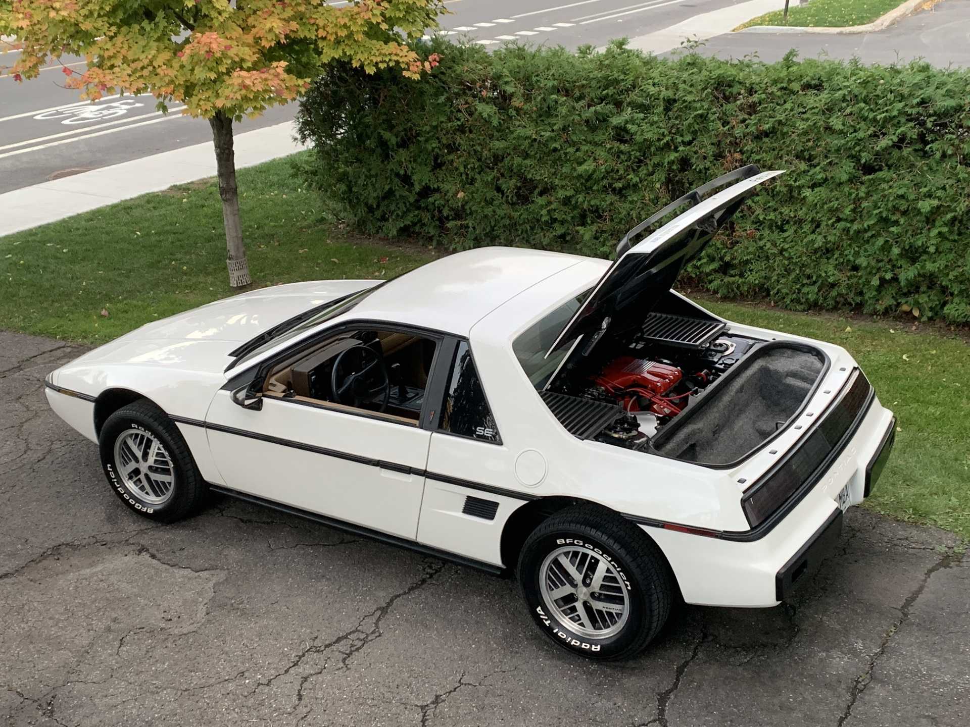
I haven't posted a picture of the car itself in a while, so here we go (three weeks ago when I washed it):
Car looks very nice Patrick! I've always wanted a white Fiero because for me that's the perfect color for any car. But regarding the AFR difference between the stamped vs Scorpion aluminum rockers could be related to the difference in metal expansion rate. Even with my muffler-less engine I can hear the rockers rattle louder when the engine is running right after cold start up until about 160F of water temp. After that I still hear it because unlike yours, my lifters are solid so they always make noise but the difference in the frequency of the rattle is clearly different after it warms up. I attribute the difference of rocker noise to a change of clearance between the valve tips and the rockers. So, in my case the valve lifts less due to the larger clearance when cold. I add .002 of clearance when cold to the recommended valve lash since I changed to the aluminum rockers because If I didn't once the engine was warmed it was hard to start. After doing compression test in all the cylinders while hot compression was down substantially because the valves were held open when hot, just enough to bleed compression through the valves. Since you have lifters that can make up the clearance hydraulically, the only remaining cause for the difference in EGO vs the steel rockers is the expansion rate of the metals. Aluminum shrinks more than steel when cold and expands more than steel at the same hotter temperatures. And since we are talking about thousands of an inch the hypothesis seems to make sense to me. That's my 2 chillings to contribute. What do you think?
Yes, I agree that having the aluminium rocker arm could change the amount of lash hot/cold with solid lifters.
I am running hydraulic lifters though, so any small changes will be compensated by the lifters. I recently changed to 0W-40 synthetic oil (with ZDDP additive extra), partly because I want to fill the lifters with with oil quickly following a cold start. The other reason for the synthetic oil is to keep it from coking too much inside the turbo when I shut down the engine.
So the ratio of a rocker arm depends on the distance from pivot to pushrod, and the distance from pivot to the roller wheel on the valve. I do not think the ratio of the rocker arm changes with temperature, because both distances change in proportion with each other. Since the rocker arm is aluminium, and aluminium is a highly conductive material, I assume that the rocker arm has the same temperature everywhere.
I reduced the amount of warmup enrichment, and the car is running better like that, but further tweaking will be needed. Getting the car to drive correctly immediately after turning the key is a quite time-consuming part of the tune!
I decided to do some benchracing! Horsepower estimation by studying a datalog recorded on 9 October 2022. A clear day with 16°C ambient temperature. Engine configuration: 180 kPa MAP with Scorpion rocker arms
The approach is to estimate horsepower by studying the 2nd gear acceleration from the datalog. 1st gear: can't hook, no traction 2nd gear: just right 3rd gear: aerodynamic drag starts to become significant
Main assumptions: Total weight: 2735 lbs (measured on truck scale) Vehicle speed sensor: calibrated with a GPS
In the 5000 to 6000 RPM range, injector duty cycle is approximately constant. So I assume that this is the power peak (well, plateau) of the engine. Therefore, I calculate power over this range.
As I work on cleaning up the front suspension, I'm working out the details of how I want to modifiy it to remove the pro-dive.
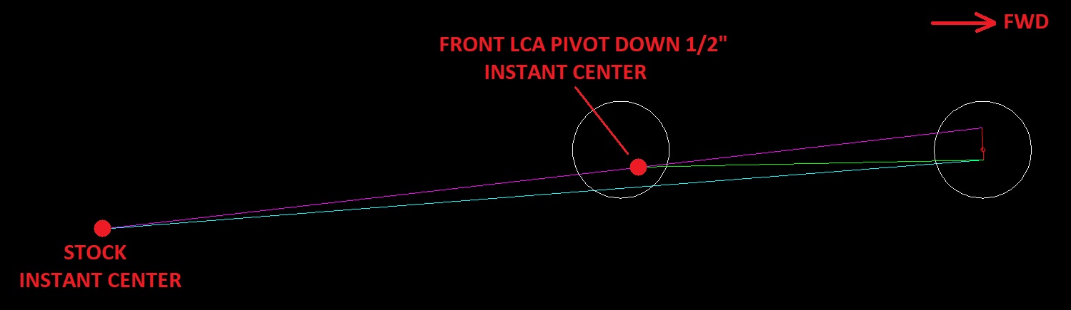
I think I will lower the front LCA pivot by about 1/2":
Stock, the side-view instant center was behind the car, some distance below the road surface. With the modification, the side-view instant center will be above the road surface, by about the same distance as the stock IC was below the road surface. As the instant center is closer to the knuckle, there will be more caster change than stock.
I probably want to increase the amount of static caster, so the caster change has less of an effect, relatively speaking. Most likely I will cut caster shim washers to shift the UCA rearwards. Maybe when I tack-weld Will's bushing shells in place, I will shift the LCAs slightly forwards.
I bought some M12x1.75x90 ARP bolts for the LCA pivots. These have a smaller hex size than typical bolts, so they require a smaller socket. Therefore, the bolt can move down, closer towards the bent lip of the crossmember, without interfering with the socket.
Factors that limit the amount I lower the front LCA pivot: 1. I don't want too much caster change. 2. There's a limit to how low I can move the steering rack to keep it in-plane with the LCA. 3. The socket for the pivot bolt will interfere with the crossmember's bent lip. 4. In the front view, the front suspension roll center moves down. It might be OK, but I don't want to make overly drastic changes.
I'm not planning on moving the rear LCA pivot up. Reasons: 1. There's not much room to move the LCA up without hitting the body. 2. Welding the holes shut and then redrilling while I'm underneath the car would be tricky... 3. This way, I'm keeping the spaceframe stock. So, if I don't like my modification, I can get another crossmember and roll back to stock.
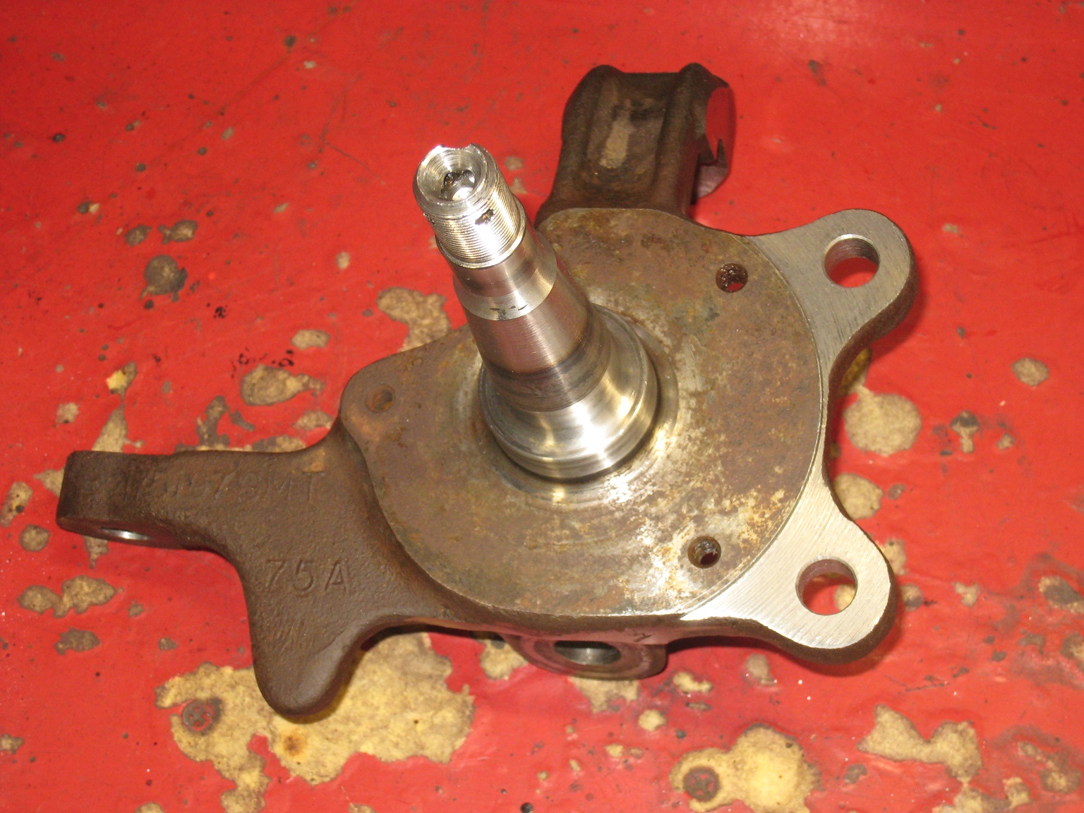
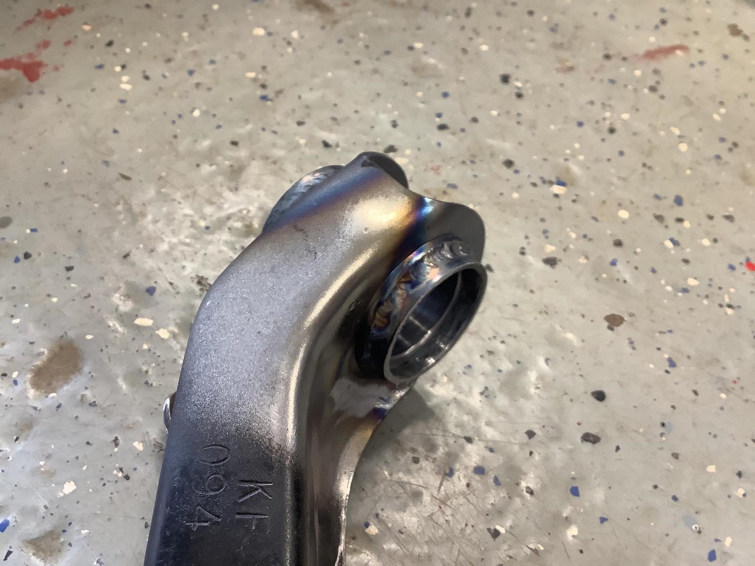
I cut the outside face of the brake caliper bracket mounting ears this weekend.
In a stock Fiero, these surfaces are as-cast.
Initially, I trying to figure out how to set up the knuckle on a milling machine, while referencing the existing machined pads for the stock caliper brackets. I was imagining this to be rather tricky...
Then, once I cleaned the knuckles, I noticed the centre drill hole that was hidden beneath the dirt!
I put the knuckles between centres on a lathe, and presto.
I kinda wish you had taken pictures of that setup in the lathe. I have drop spindles on my car, and they actually have significantly less material to machine off, it's a big part of the reason I want to make custom spindles for the car so that the calipers mount securely to a machined face. Mine will probably use unit bearing hubs in 5x114.3 so I can have the largest wheel selection options.
I'm looking forward to hearing how your suspension mods work out!
------------------ "I am not what you so glibly call to be a civilized man. I have broken with society for reasons which I alone am able to appreciate. I am therefore not subject to it's stupid laws, and I ask you to never allude to them in my presence again."
I invited Lou Dias to trash me in my own thread, he refused. sorry. if he trashes your thread going after me. I tried.
Fieroguru, I've seen you post on the forum that using the as-cast surface is ill-advised. I would have probably come to that conclusion on my own, but I give you 5% credit!
With a big/solid enough lathe, there won't be vibration/scariness. This also assumes you keep the RPM down, like below 100 or less. In a marginal case, you could add a counterweight.
I would suggest the same sort of setup like I did for my tire mounting tool:
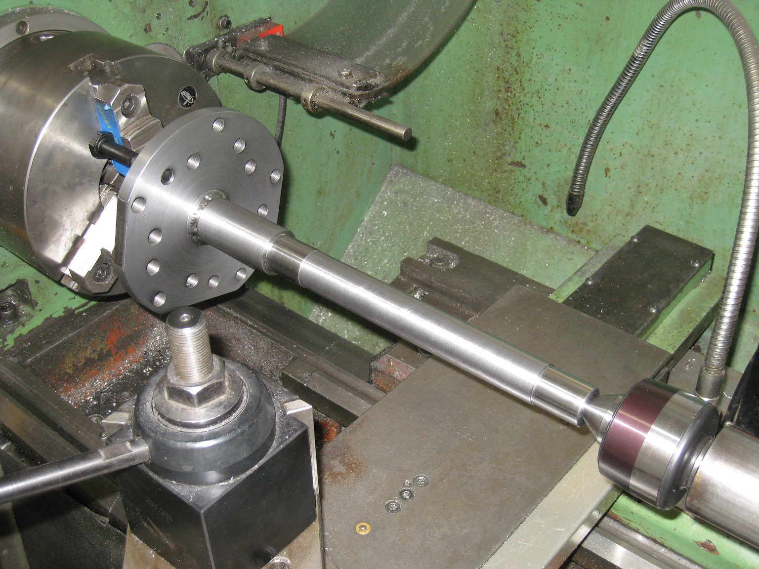
When I want to turn between centres, in most cases, I chuck a piece of mild steel rod with a 60° cone (generally reusing the same one) and use that as the centre in the headstock end. Before use, I take a skim cut with the compound slide to make the 60° cone concentric with the headstock rotation.
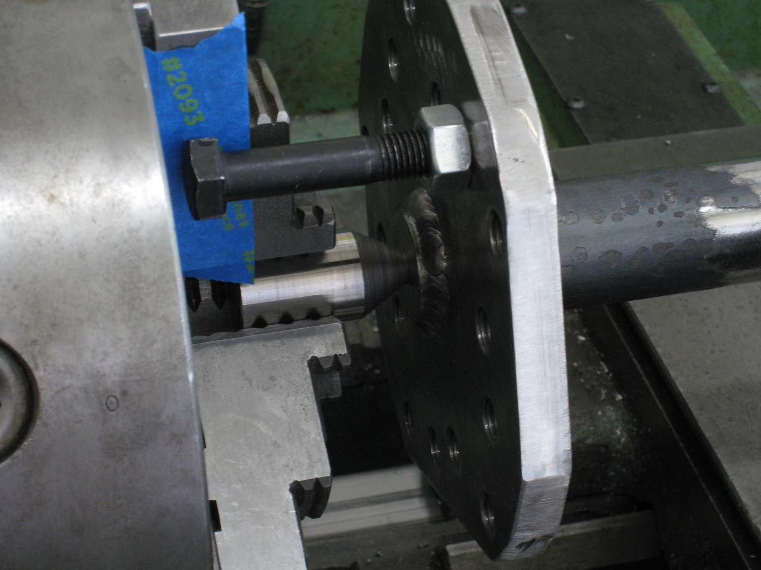
A bolt+jam nut is a convenient way to drive the part, if your part happens to have a threaded flange:
On the Fiero knuckle, a simiar bolt+jam nut could be used in the caliper mounting bracket hole. In the general case, use a lathe dog.
That green lathe at work was pretty nice, but I don't have access to it anymore. That lathe was included as part of a recent divestiture...
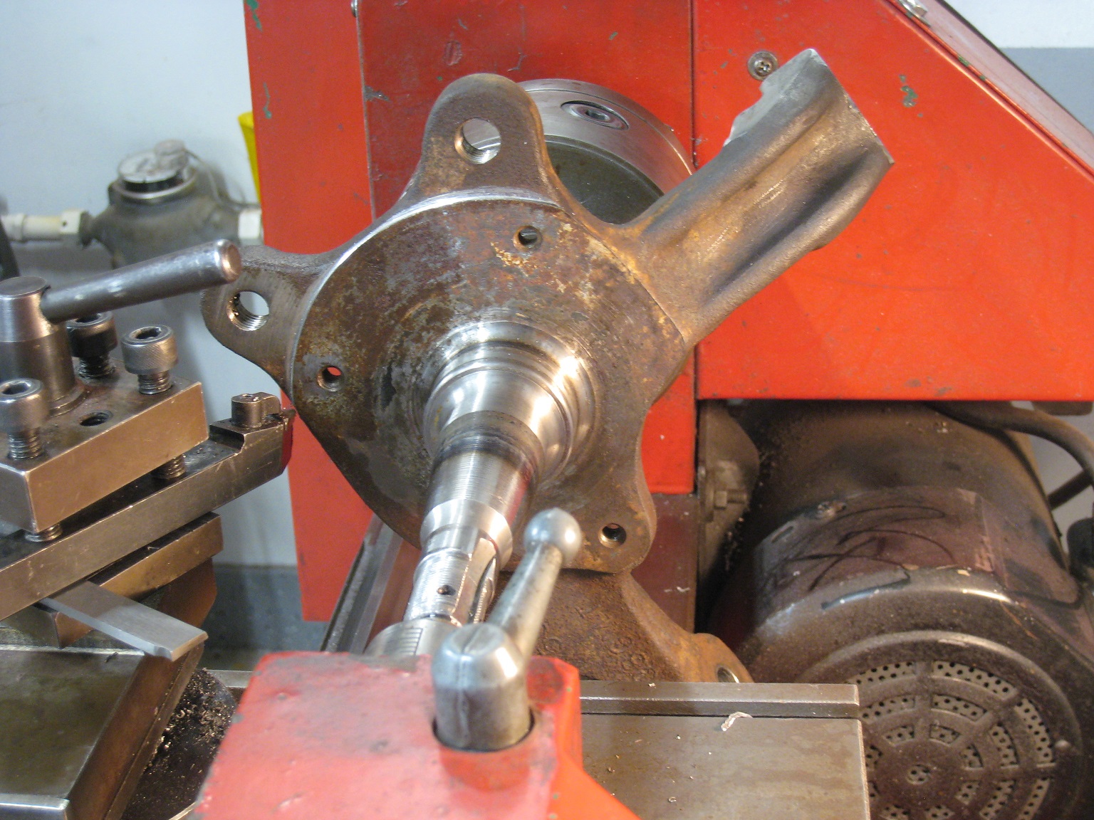
I instead used my dad's light-duty 9x20 lathe.
The 9x20 doesn't have the swing clearance to spin the knuckle all the way around. However, since I only needed to cut material from a ~100° arc, that worked out with me manually pushing the knuckle back and forth. Between each stroke, I turned the handwheels to set the cutting depth.
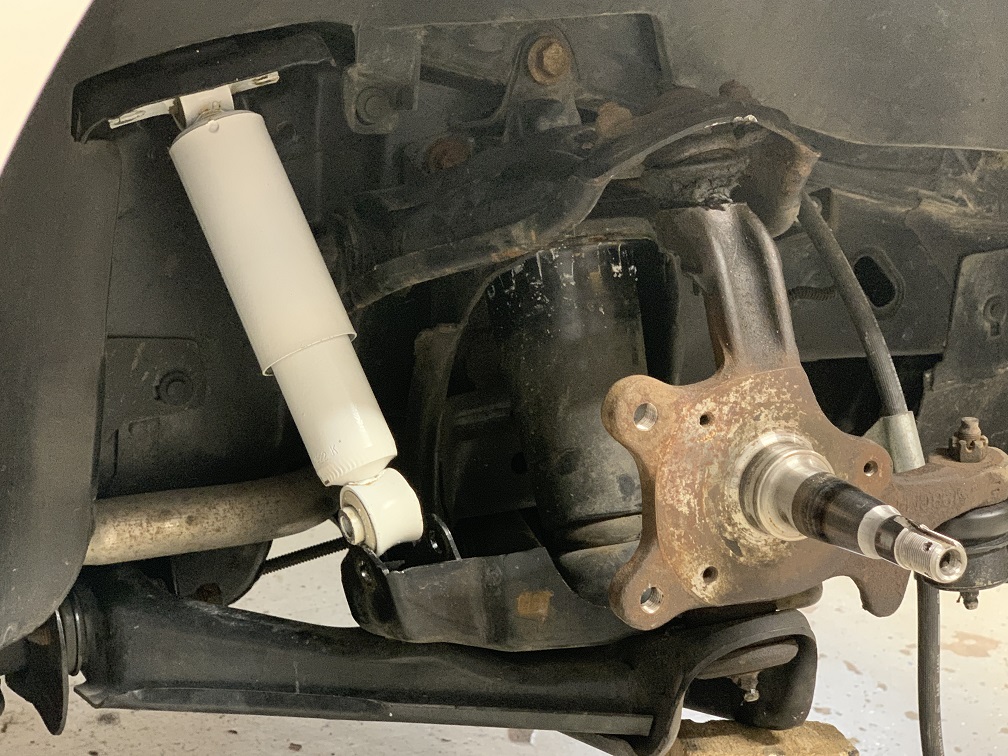
I don't have a good photo showing the overall setup, but I snapped this one:
262, I don't know if your concern is about about insufficient thread engagement in your knuckles, but if that's the case, you could drill out the threaded holes and use nuts on the other side in the interim.
I have done a decent amount with a manual mill, and a fair amount with a cnc mill and cnc lathe, but only a handful of jobs with a manual lathe without a blast door, and they were all round aluminum stock kinda jobs. So imagining the spindle on there right near your face is scary. I have to start messing with my lathe, first I need to get a set of tools and quick change doodads.
But I was re-reading through your thread and I have a couple comments.
Regular old split lock washers have always worked great for me on joints that loosen up due to thermal expansion and cooling, I put them on everything subjected to thermal cycling or vibration.
I had recommended POR-15 high temp exhaust coating for turbo headers to you in a PM once. I take it back, it was much better than VHT, but it did not hold up for more than 6 months in a turbo application. Would probably be great for heatshields and brackets. How has your cerakote held up?
[This message has been edited by zkhennings (edited 03-14-2023).]
If you tighten your bolt a minimum amount, the split lock washer flattens and becomes a solid spacer. At that point, the only added value it has are the sharp edges which can bite into the surface and bolt head, preventing unscrewing.
At that point, you might as well use something more designed to prevent unscrewing, such as a serrated head, a star washer with multiple teeth, or the Nord-lock style of washer.
With regards to temperature variations, I think you should just arrange so that your bolts remain sufficiently stretched throughout the temperature range of the assembly.
I haven't had any problems with exhaust manifold to head gaskets since I replaced the gaskets with Fel-Pro and I used the wedge-lock bolts. I think the main issue was the previous cheap exhaust gaskets burning out, causing a total loss of bolt load. The wedge-lock bolts were a bonus on top, but not the main fix. I retained the stock 2.8 stud-bolts in three positions, in order to mount the stock 2.8 exhaust manifold shield.
The Cerakote has been generally OK on most heat shields, but not a slam dunk.
Some signs of rust showed up on the hottest heat shield (with exposure to rain); the shield covering the turbine housing. I rubbed away the rust with Scotchbrite, and then resprayed over the Cerakote with VHT in the same colour.
I think that some sort of plating process might work better...
[This message has been edited by pmbrunelle (edited 03-15-2023).]
The purpose of the split washer is to put tension on the bolt, they make wave style washers that do the same job as well, split washers is just the cheapest way to manufacture them. It is essentially a single coil spring that helps prevent loosening when there are slight changes in clamping force from vibration or temperature change. I generally use a high grade split washer (8/10.9 or higher) as they take a lot more force to flatten, and generally hold their shape even when compressed for a long time.
I agree your exhaust issues were from the gaskets, but just as a general suggestion they do work very well in my experience. I use them a lot with exhaust flanges of all kinds.
Also try out the Eastman brand paints, you can get the 2K high temp paint in spray cans where you break an internal activator compartment and have limited time to use it. I thnink it would work great for heat shields.
[This message has been edited by zkhennings (edited 03-15-2023).]
How much force does it take to flatten an M8 split washer? I'm guessing on the order of 250 lbs?
If you have a class 10.9 M8 bolt at 75% proof load, you have 5123 lbs of clamping load.
If the bolt somehow relaxes to the point that the split washer is now working as a spring (versus solid), then something seriously wrong has already occurred, and the bolted joint has already failed, in my opinion.
The purpose of the split washer is to put tension on the bolt, they make wave style washers that do the same job as well, split washers is just the cheapest way to manufacture them. It is essentially a single coil spring that helps prevent loosening when there are slight changes in clamping force from vibration or temperature change.
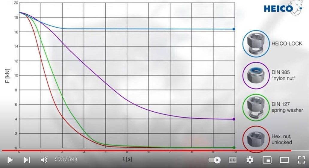
In my reliability training we watched an old video about bolted joints subjected to vibrations via the junker test. What we learned was the normal lock washers performed about the same at resisting loosening from vibration as a bolt w/o lock washer. Loctite was the winner in that video. My reliability instructor's mantra was Loctite on every bolt, every time.
Here is a video of a newer junker test that shows the same result (source for the chart above) with the lock washer and improved holding of their custom washers.
This is the kind of content I like to see in a forum, Thanks for posting it!
------------------ "I am not what you so glibly call to be a civilized man. I have broken with society for reasons which I alone am able to appreciate. I am therefore not subject to it's stupid laws, and I ask you to never allude to them in my presence again."
I invited Lou Dias to trash me in my own thread, he refused. sorry. if he trashes your thread going after me. I tried.
262, I don't know if your concern is about about insufficient thread engagement in your knuckles, but if that's the case, you could drill out the threaded holes and use nuts on the other side in the interim.
thread engagement was a concern one of the concerns, the casting is just very thin at the caliper ears, to an almost uncomfortable degree. the aftermarket part was clearly made to a lower standard than the OEM, which is not entirely surprising, but still disappointing.
machining that surface must have taken a while doing it by hand like that! the outcome however looks great, good job!
Originally posted by pmbrunelle: At the higher MAP level allowed by the new clutch, the VR crank sensor analog-to-digital Maxim MAX9924 interface has been malfunctioning and causing the ECU to lose synchronization with the crankshaft.
I did a quick-and-dirty test with a 4-pin HEI module acting as the crank sensor interface; it worked well. Over this winter I'll figure how to install the HEI module cleanly.
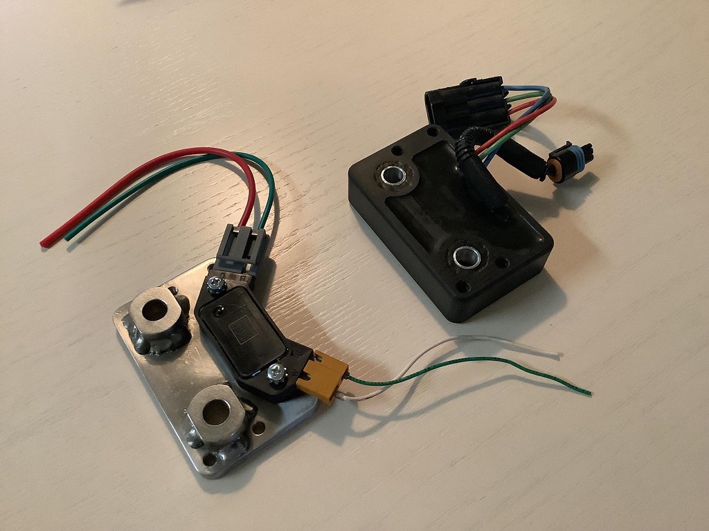
Last weekend, I completed a support bracket for the HEI module from a piece of laser-cut metal with welded-on spacers.
Because the HEI module is grounded via its case, I wanted to use a metallic non-corroding material to ensure electrical conductivity to the engine block. I used stainless steel 304.
Here are the new and old solutions side-by-side:
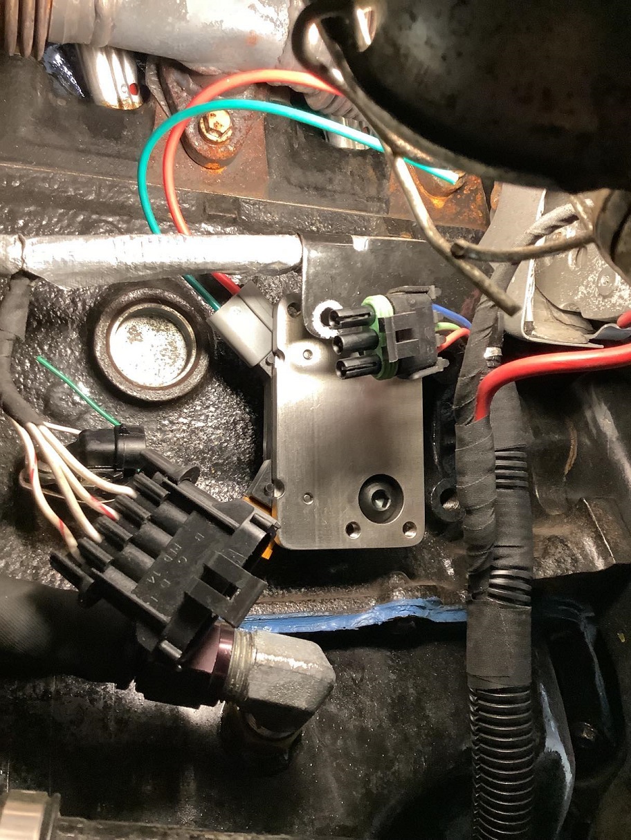
The support bracket screws onto the engine block:
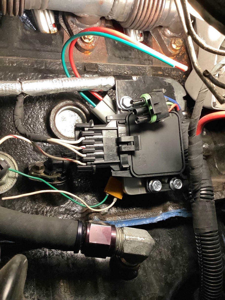
With the knock module installed like before:
I still need to do the wiring to finish this modification.
I really like the use of the HEI module, mainly because it's an off the shelf part, that if it fails, is relatively quick and easy to acquire. Nice work.
------------------ "I am not what you so glibly call to be a civilized man. I have broken with society for reasons which I alone am able to appreciate. I am therefore not subject to it's stupid laws, and I ask you to never allude to them in my presence again."
I invited Lou Dias to trash me in my own thread, he refused. sorry. if he trashes your thread going after me. I tried.
I haven't posted a picture of the car itself in a while, so here we go (three weeks ago when I washed it):
You've done a fantastic job with this car, and I'm very impressed with the work you've done in the engine bay, etc. You've actually "engineered" components yourself, and not just bought stuff off the shelf and slapped things together. You have every right to be very proud of the work you've done.
I don't know if I missed it... but how do you enjoy driving the car? Compared with stock (if it was running well at all originally)?
Did you have any opportunity to drive it as a 3.1 without the turbo? I'd converted mine to a 3.1 (ended up being 3.2L with the larger pistons), and I didn't notice a difference at all, but my car had many other issues at the time. I still plan to go through it all, but in a storage unit it sits! Haha...
From 2008 to 2016 I drove my first Fiero with a near-stock 2.8 L V6 (and 5-speed Isuzu), so I have that as a point of reference.
I never drove this 3.2 L car without the turbo. That said, the turbo sizing is not like that of a typical modern 4-cylinder turbo car; the turbo only really wakes up and boosts the midrange and top end. Below around 3000 RPM in calm driving, the turbo isn't being spooled much, so the car works like it has a naturally aspirated 3.2 L V6.
Going from 2837 cc to 3192 cc is a 13% increase. My car has 7.4 compression compared to a stock Fiero's 8.9, so I think the reduction in compression results in a 5% torque reduction. Therefore, I think that my engine makes about 8% more (naturally aspirated) torque than a stock Fiero engine produces.
From experimenting with different boost pressures, I think a 20% torque change is needed to result in a "nice" noticeable improvement on the butt dyno. Others may have more sensitive butt dynos than I do.
In terms of daily driveability/friendliness, the best mod I think I did was to run the M19 Muncie Performance transmission gearing available in the 1984 4-cylinder Fiero.
That results in a 14% torque increase. Additionally, when taking off from a stop, clutch engagement occurs at a 14% lower road speed than with a stock Fiero.
So, in terms of the amount of clutch slippage needed to get moving from a stop, I count the ratio effect twice (squaring it), and so I consider clutch slippage on takeoff to be improved by 30%.
When I drive my car in town, I don't have to slip the clutch much to get going. It's really quite pleasant in the city (from memory, better than stock Fiero). You don't have to rev the engine much, and it's quite hard to stall on takeoff. Even uphill starts are easy to do.
Displacement helps, but I think the gearing was key in making my car drive nicely in town. The turbo of course makes the engine pull harder when you open up the throttle, and that is satisfying in a different way.
There is some room for improvement in the powertrain, but right now I find the stock 84-87 Fiero brakes/suspension to be the weakest area of my Fiero's driving experience. The car handles like a marshmallow! I think I will like the handling better with the wheel/tire/brake/suspension mods I'm working on.
[This message has been edited by pmbrunelle (edited 05-09-2023).]
In terms of daily driveability/friendliness, the best mod I think I did was to run the M19 Muncie Performance transmission gearing available in the 1984 4-cylinder Fiero.
I wanted to respond to this separately, because I totally agree. I had a 1985 Fiero GT 4-Speed many years ago. I bought it used, and sold it two years later. But I drove it around a lot, did a few things to it, but really what was unique about it is that the heads had been decked. It was done before I got it, but the heads had been decked to get rid of a cyl head warp, and it bumped the compression up a fair amount to something like 9.1 or 9.2 (I can't really remember). The intake had been milled to match the cyl heads too, so when I tried to put another intake on (after I'd port-matched a spare), it wouldn't fit exactly as it should. But in addition to the compression, it also had the 4.10:1 4-Speed performance transmission from a 1984 Fiero dropped into it as well. The acceleration was really significant. It was way quicker off the line than my 1987 Fiero SE / V6 that (at the time) had a 3.33:1 GX3 automatic. It would pull away hard, but then around 65-70 the automatic Fiero would begin pulling on it (which didn't make much sense to me, but never the less). But yes, I can only imagine how much fun that little car is (with your modifications) and that 4.10:1 4-Speed in there!
quote
Originally posted by pmbrunelle: There is some room for improvement in the powertrain, but right now I find the stock 84-87 Fiero brakes/suspension to be the weakest area of my Fiero's driving experience. The car handles like a marshmallow! I think I will like the handling better with the wheel/tire/brake/suspension mods I'm working on.
Like ~15-20 years ago... I was blowing all my paychecks on Fieros, and I had like 5 of them at the same time at one point. Depending on what you're looking for, what I found worked best was to get the WS6 springs, and mild-shocks, either Y99-rate shocks, or even if you want a bit more aggressive... the KYB Gas-Adjust shocks. I then also went with poly bushings on the front sway bar. That's with all the stock geometry of course, but that seemed to be the best of both worlds for me. The stiffer springs really reduced any roll I was getting during cornering, and the mild shocks worked well to prevent any significant road vibration. I added a rear sway bar as well, but that added some unpredictable oversteer in situations that I wasn't comfortable with.
I had a few other combinations that sucked. I went with all poly and KYBs (and normal Y99 springs that were original), and that felt like **** . Every pothole or dip felt like a jackhammer. The springs were doing nothing.
At one point I also had the WS6 rated springs (which I got new from NAPA), and KONIs... and that was too rigid, but it was better than the previous, which had the soft springs.
I mean, I'm old now... mid 40s. So what I would be looking for is different than you of course, but for me... I like sort of the "German" handling, which is stiff springs, and softer shocks. That gives more of the feeling that you might get from a Golf GTI or a Jetta, or even a Porsche 944 for example.
For brakes, you'll probably make all your own stuff, but I was having a LOT of issues with brake fade. I mean... I was in my early 20s, and I was basically flooring it at every light, and getting stopped at every light. My front rotors at the end of the day would be glowing red. The fade was horrible to the point that my braking ability almost halved when they were really, really hot. Anyone who says the stock Fiero brakes are sufficient for the stock V6 is probably not driving it spiritedly. If someone was going to actually use the Fiero for an SCCA Solo-1/2 event... the Fiero would fail hard.
I noticed the most significant improvement I could find, across the board, was replacing the stock front rotors with cross-drilled rotors from the Fiero Store. I never had a single problem after that. And to be clear, I'd replaced the front rotors a couple of times because they'd warped due to my very aggressive style of driving down here in Miami.
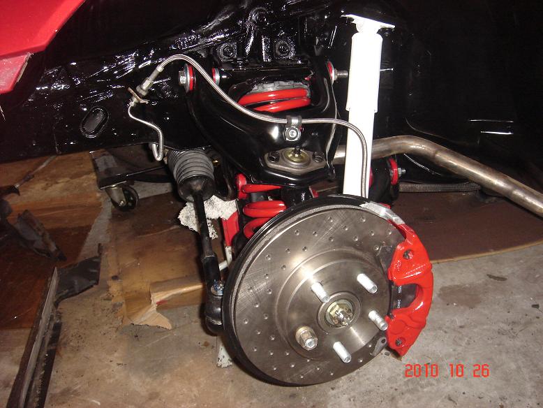
This is what I ended up doing before I put my car into storage:
This was literally weeks before I put it into storage (where it sits currently)... it was like 13 years ago... which sadly is how long it's been in storage. Everything here is mostly stock. I've gone with poly bushings (but I may replace the lowers with rubber bushings when I get it out), and these are WS6 springs, and KYB shocks. The brakes are from the "Grand Am" brake upgrade. Not sure if you can still buy that anymore, but I got it from the Fiero Store I think... years ago. Probably better options now...
EDIT: I wanted to say, I really like the fact that you're keeping the car aesthetically looking stock. It looks so sharp the way you've done it. You see some "modified" and custom Fieros on eBay that people have gone through, and it really makes me sad. You've done such a good job improving the car, while not making it look stupid!
[This message has been edited by 82-T/A [At Work] (edited 05-10-2023).]
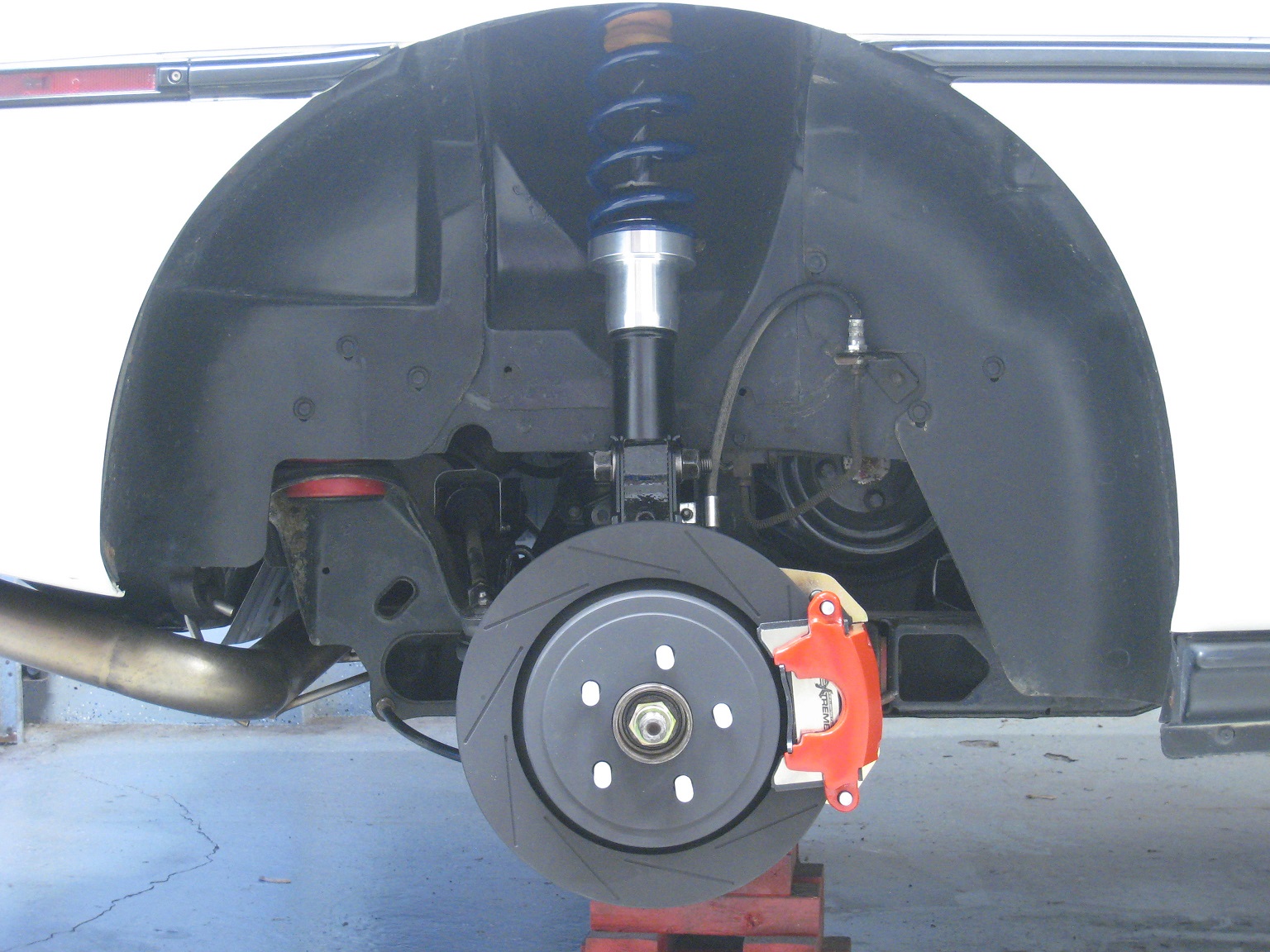
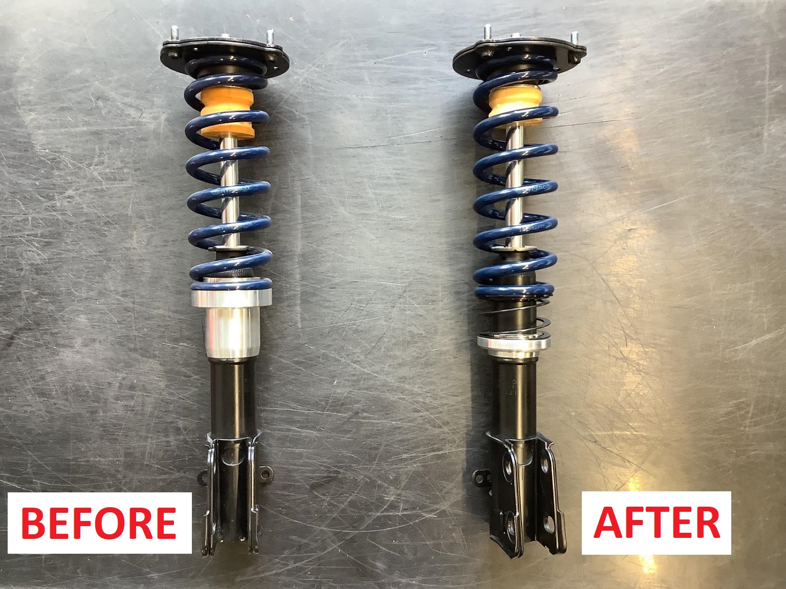
The new struts and rear LeBaron brakes are now installed.
These struts will give room for the 17x9 ET+40 wheels and 255/40R17 tires that will be going on the rear of the car. I'm using a custom aluminium spring perch sitting on top of the KYB strut's weld bead.
Besides polyurethane bushings in the rear control arms, the rear suspension is otherwise stock in this incarnation of the White Bug.
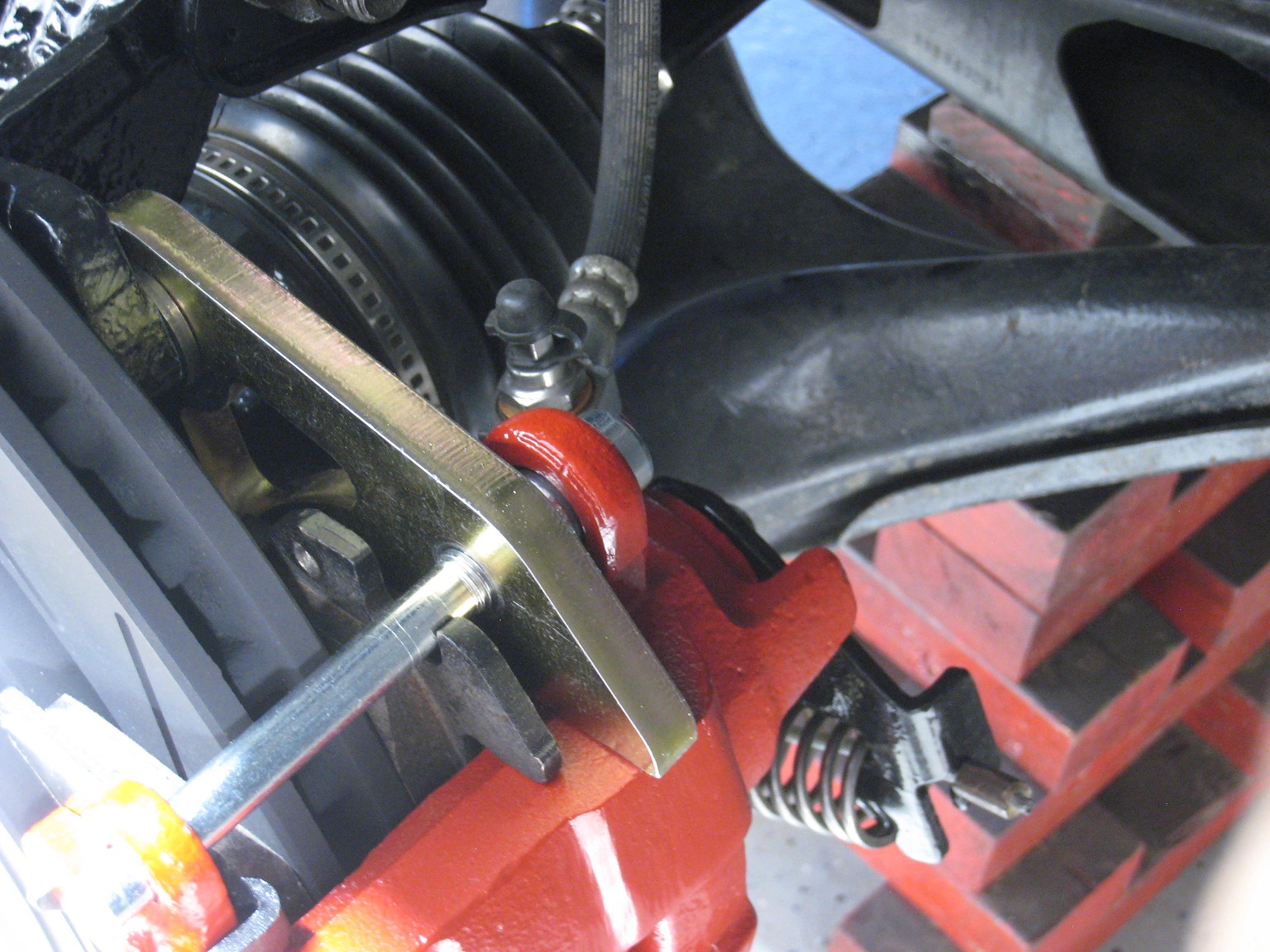
*****Rear Brakes***** -LeBaron rotor: Raybestos 7993R, slotted and balanced by myself. -Caliper bracket: 3/8" steel, yellow zinc plated, cut by sendcutsend. -Caliper: 1985 Cadillac Seville, modified for use with banjo bolt bleeders: https://www.fiero.nl/forum/Forum2/HTML/144809.html -Banjo bolt bleeder: Goodridge 992-31BNC -Hub: stock Fiero hub, pilot diameter turned down to fit LeBaron centrebore. -Pads: Powerstop Z26, GG friction rating.
Perhaps at some later time I'll try to make a drum-in-hat parking brake work, but for now, I'll be rolling with the upside-down Cadillac calipers and banjo bolt bleeders.
if you still have the original bleeders installed as well, one of these reverse style bleeders may help expel air from the caliper slightly better by pumping in through the bottom and out through the banjo bolt, then use the banjo bleeder to get the air from the lines. https://www.amazon.com/Phoe...s%2Caps%2C288&sr=8-2
or maybe it works well enough standalone.
------------------ "I am not what you so glibly call to be a civilized man. I have broken with society for reasons which I alone am able to appreciate. I am therefore not subject to it's stupid laws, and I ask you to never allude to them in my presence again."
I invited Lou Dias to trash me in my own thread, he refused. sorry. if he trashes your thread going after me. I tried.
I'm guessing that the banjo bleeder will be sufficient to fill the system from dry (to be seen).
However, for future maintenance brake fluid flushes, I'll definitely have use the original bleeders in some way, because sucking fluid from the banjo bleeder won't replace the brake fluid that's inside the caliper.
I've never tried reverse pressure bleeding. Does brake fluid ooze out of the bleeder threads when you do this? I don't like the mess that brake fluid makes (bad for paint), but I can always rinse a mess with a garden hose.
I have always put teflon on the the threads of the bleeder either way. typically, if you open the bleeder enough, it doesn't make much of a mess. I actually prefer the reverse bleeder to any other bleeding method I have tried.
------------------ "I am not what you so glibly call to be a civilized man. I have broken with society for reasons which I alone am able to appreciate. I am therefore not subject to it's stupid laws, and I ask you to never allude to them in my presence again."
I invited Lou Dias to trash me in my own thread, he refused. sorry. if he trashes your thread going after me. I tried.
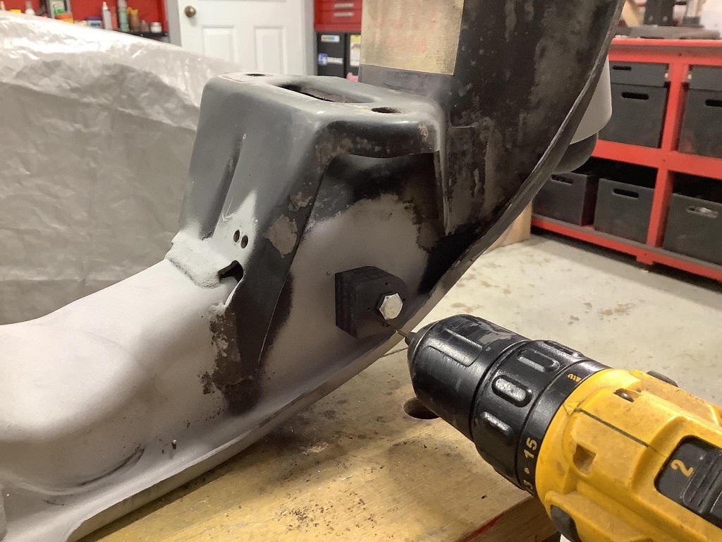
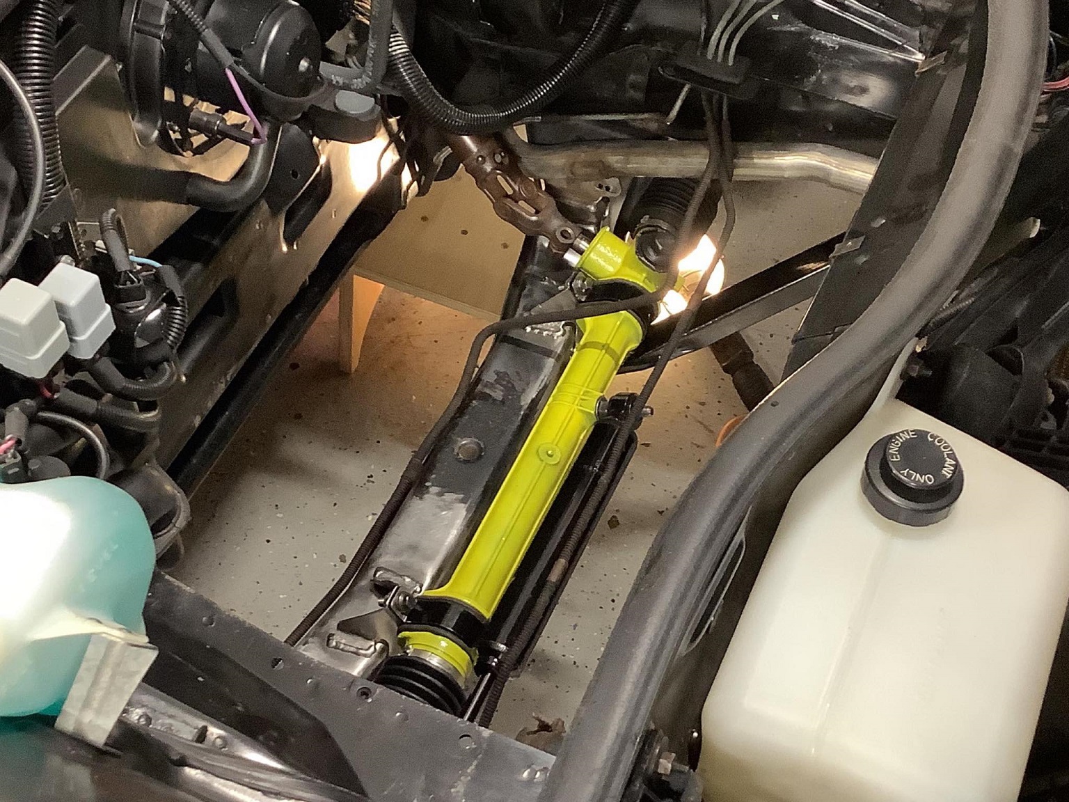
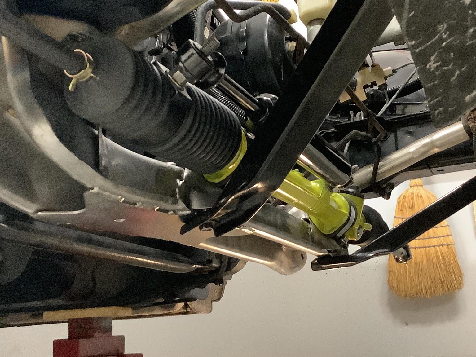
I started the anti-dive mod on my front suspension, which mainly consists of moving the forward lower control arm pivots down 3/8".
To locate the new pivot holes, I made a drill guide bushing which centers in the original hole. I then used the flat side of the guide bushing to clock the guide hole correctly.
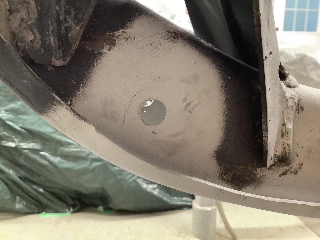
Now that the pilot holes are drilled, I need to weld the original holes shut. Then, I can drill out the pilot holes to the correct size.
Welding the stock LCA pivot holes shut went well. Now, I can drill out the pilot holes to the correct size:
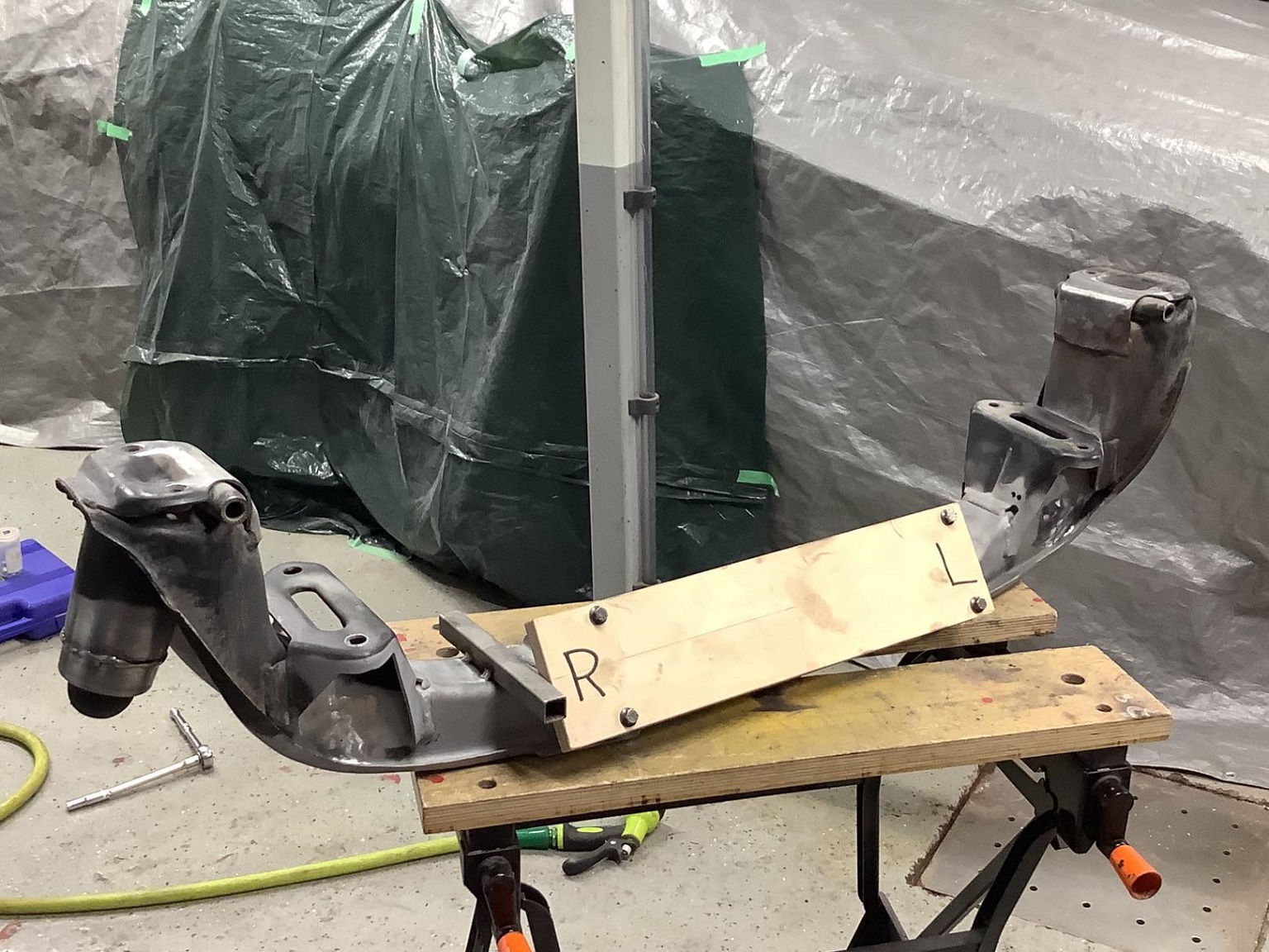
I made a plywood jig to simulate the steering rack:
As I'm moving the LCA down, I want to move the steering rack down as well. The steering rack mounts need to be cut off, shortened, and then rewelded to the crossmember.
I temporarily welded a steel tube to the crossmember, touching the edge of the plywood jig. This is a reference, so that when I reweld the steering rack mounts to the crossmember, the left-right positioning will be correct.
The steering rack moved down by 0.5" appears to fit without issues.
This was a test fit:
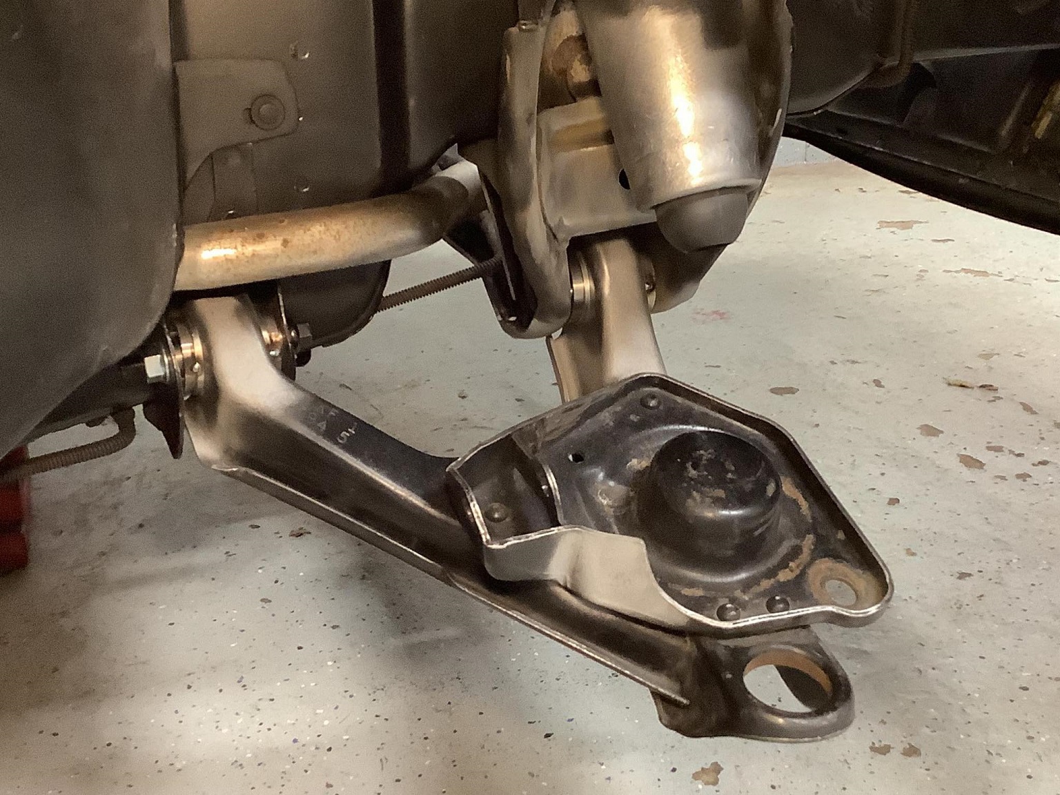
With the crossmember (temporarily) in place, I tack-welded Will's spherical bearing shells to the lower control arms:
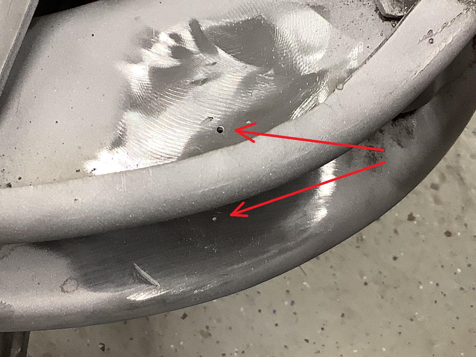
Fieros don't appear to have been built with much precision. The LCA pivots on the right side of the car were spaced ~4 mm closer together than those on the left side of the car. I don't think this car was ever in an accident. The size of the mill and drill pads gives an idea of the spaceframe's tolerances.
Fieros don't appear to have been built with much precision.... The size of the mill and drill pads gives an idea of the spaceframe's tolerances.
I have seen at least 1 car where the hole for the mill and drill pads was outside of the pad area. The whole purpose of the mill and drill was to achieve good panel alignment (cosmetics) without needing to catch up to their peers with their metal design, stamping and assembly processes.
your progress looks great! there are times I wish I had built my car more or less in "stages" instead of all at once. I find myself with less things that are finished, and more things that individually need attention. In your case, the steps of your build all seem much more complete before you move onto the new step.
------------------ "I am not what you so glibly call to be a civilized man. I have broken with society for reasons which I alone am able to appreciate. I am therefore not subject to it's stupid laws, and I ask you to never allude to them in my presence again."
I invited Lou Dias to trash me in my own thread, he refused. sorry. if he trashes your thread going after me. I tried.
The more times I see your white Fiero, the more and more impressed with it I become. You've done such a good job... it's 100% the product of an engineer. I'm so glad you're keeping it stock looking. It's such a striking design, and with the effort and work you're putting into it... it's going to be such a fantastic car.
With the crossmember (temporarily) in place, I tack-welded Will's spherical bearing shells to the lower control arms:
Fieros don't appear to have been built with much precision. The LCA pivots on the right side of the car were spaced ~4 mm closer together than those on the left side of the car. I don't think this car was ever in an accident. The size of the mill and drill pads gives an idea of the spaceframe's tolerances.
There's a locating pin on the crossmember, but only on one side. I thought the bolt holes on the other side were slotted, so maybe there's some room to bump it around to get the two sides closer before you finish weld them. Or maybe you already have and this message is too late
Originally posted by ericjon262: your progress looks great! there are times I wish I had built my car more or less in "stages" instead of all at once. I find myself with less things that are finished, and more things that individually need attention. In your case, the steps of your build all seem much more complete before you move onto the new step.
I like to take bite-sized chunks that aren't overwhelming. But, there's no one way to modify a car!
quote
Originally posted by 82-T/A [At Work]: The more times I see your white Fiero, the more and more impressed with it I become. You've done such a good job... it's 100% the product of an engineer. I'm so glad you're keeping it stock looking. It's such a striking design, and with the effort and work you're putting into it... it's going to be such a fantastic car.
Glad you like it!
In about two weeks, the car should be running again with new tires/wheels/brakes/suspension. I'll see how I like it then.
quote
Originally posted by Will: There's a locating pin on the crossmember, but only on one side. I thought the bolt holes on the other side were slotted, so maybe there's some room to bump it around to get the two sides closer before you finish weld them. Or maybe you already have and this message is too late
On my 1985 Fiero, there is no locating pin. There are four bolts holding the crossmember to the underside of the frame rails. One bolt hole on the crossmember is close-fitting the the bolt. On the opposite side of the car, a slot on the crossmember (again, close-fitting to its bolt, along its short dimension) blocks rotation. Together, the hole and slot dully define the crossmember's position in 3 degrees of freedom. There is no adjustment available (not without changing the locating concept).
The UCA position is determined by the crossmember. Caster is determined by the relative fore/aft positioning of the UCA versus the LCA. To get the caster approximately correct and equal on both sides, I positioned the LCAs relative to the crossmember. The LCA positioning relative to the body-mounted pivot ears was a consequence of the aforementioned procedure.
I got the bearing shells TIG-welded by a guy near my parents' place:
In retrospect (I often realise these things AFTER completing the job), I should have adjusted the (relatively bendable) rear body-mounted pivot ears with a BFH to make things appear more symmetric between both sides. Oh well, I didn't do that! My mods don't always end up perfect, but that's OK. The mistakes remind me of the human element involved (myself)...
I'll give you some feedback (not right now though) on the bearing shells, over in the bearing shell thread.
I goofed with my initial rear strut setup. I had a 400 lb/in spring, just barely preloaded. I eventually figured out that the rear of the car would end up way too high.
To correct the situation, I lowered the spring perch on the strut, and then to take up the play of the spring at full droop, I inserted an Eibach helper spring.
Expected ride frequencies are: Front 1.75 Hz Rear 2.07 Hz
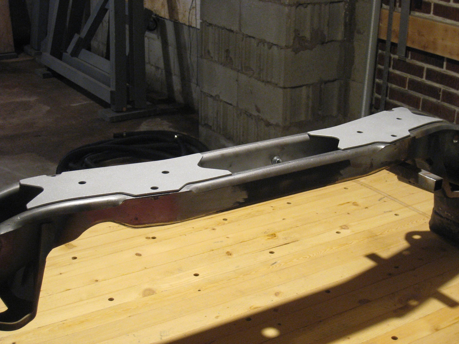
Since I am lowering the steering rack, the notch for the steering column clearance needs to move down, weakening the crossmember.
Therefore, I prepared some laser-cut reinforcing plates for the front crossmember.
I'll weld them on shortly.
I too did not notice a locating pin on any of the three 84-87 crossemembers I have handled, that might be an '88 feature.
the later crossemembers have a similar reinforcement to your laser cut parts. my 85 had a non-reinforced crossmember as well, I swapped one from an 87 in when I did my anti-dive modification, while I didn't know there was a difference before I started the modification, I did welcome the extra bracing, your design looks well executed.
------------------ "I am not what you so glibly call to be a civilized man. I have broken with society for reasons which I alone am able to appreciate. I am therefore not subject to it's stupid laws, and I ask you to never allude to them in my presence again."
I invited Lou Dias to trash me in my own thread, he refused. sorry. if he trashes your thread going after me. I tried.