Well, probably the inner flange of the rotors wouldn't fit over your wheel spacers (too small). The spacer is too large in diameter for fit on the 88 or Corvette rotor.
Do I win anything...
------------------ fierogt28
88 GT, Loaded, 5-speed. 88 GT, 5-speed. All original.
After looking again, maybe you decided that smooth rotors just would not look right on a Ferrari so you drilled cool looking cooling holes? I could see where that would take a lot of time...
Well, cptsnoopy and doublec4 figured it out. I haven’t a clue what ArbinShire or fierogt28 were thinking. Weren’t you guys paying attention about the part with the HT Motorsports 6" track width tubular control arms? Or when I mentioned the spacers were for sale? I’m starting to think you guys are just looking at the pretty pictures.
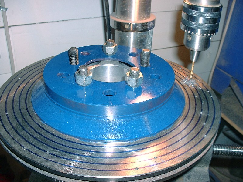
Anyways, the Corvette rotors were plain-Jane's and weren't cross-drilled, and they had to be redrilled for the 5 X 100 mm bolt pattern since stock Corvette is 5 X 4.75”. I didn’t trust myself enough to drill the bolt circle so I took the rotors to the machine shop which cost me $20 per rotor. At least I don’t have to worry about them wobbling around off-center like I’m sure they would’ve done had I drilled them! Cross drilling them was something I was sure I could do though. In my opinion, there’s nothing sexier on a big brake package than to have all those little holes in a neat little spiral pattern. I’d never done this before but I figured since the rotors were free I didn’t have much to lose.
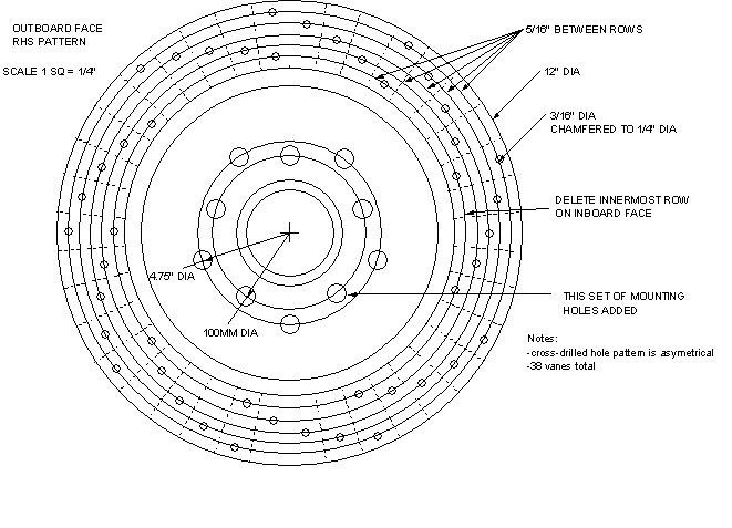
The first step was to figure out how the vanes were oriented between the inner and outer rotor faces since I didn’t want to drill into any of them. It turned out they ran radially outwards, not in a spiral like I had hoped. I prefer the look of spiraled holes as opposed to the one that run straight out from the center, but after pondering about it a little, I realized the vane orientation didn’t matter, so I created a little drawing and a template to guide me. (For those of you old enough to remember, I could probably have made use of my old Spirograph to create the template!)
Then I set up the old bearing and spacer in the drill press. The bearing was useful since it turned the rotor into a handy-dandy turntable of sorts, while the 3" spacer kept the rotor from hitting the vise. Once my jig was lined up and leveled, I attached the rotor to the spacer with some lug nuts and was ready to start drawing out my concentric circles. I chucked a marker into the drill, set the correct radius up, lowered the drill just like needle on a vinyl record and spun the rotor. I made 5 concentric rings each 5/16” smaller in radius than the previous one by turning the adjuster cranks on the sliding vise.
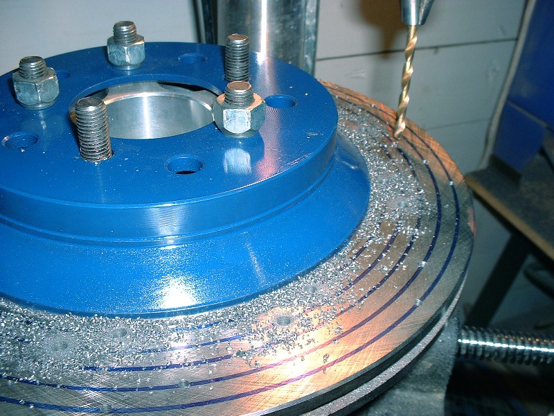
Next I used my template to mark where the holes needed to go by lining up the vanes on the template with the vanes on the rotor. One of the benefits of drilling them in the pattern I chose is that the space between each vane only has one hole, except for some of the vanes with the inner and outer-most holes, which have two. By doing it this way, most adjacent holes are separated by a vane, creating an impediment for cracks to propagate from hole to hole. In the few spaces that have two holes, the largest possible distance (greatest material) separates the holes. With the hole locations marked, I started drilling 1/8” pilot holes.
Then I stepped it up by drilling the final diameter. I chose 3/16” after researching typical cross drilled rotors on the internet. At first it seemed a little big, but I like it now.
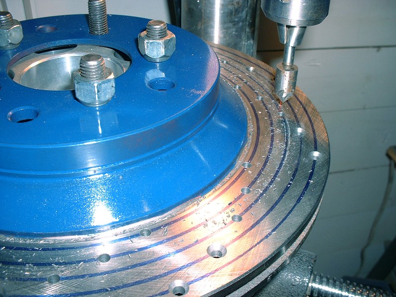
The final step was to chamfer all the holes to ¼” diameter, more for looks, but also de-burr them and provide greater stress relief. For the previous steps, I drilled right through both layers of the rotor each time, but for the chamfering, I had to do each side separately, obviously.
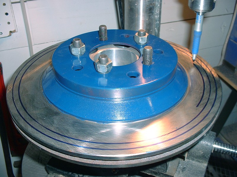
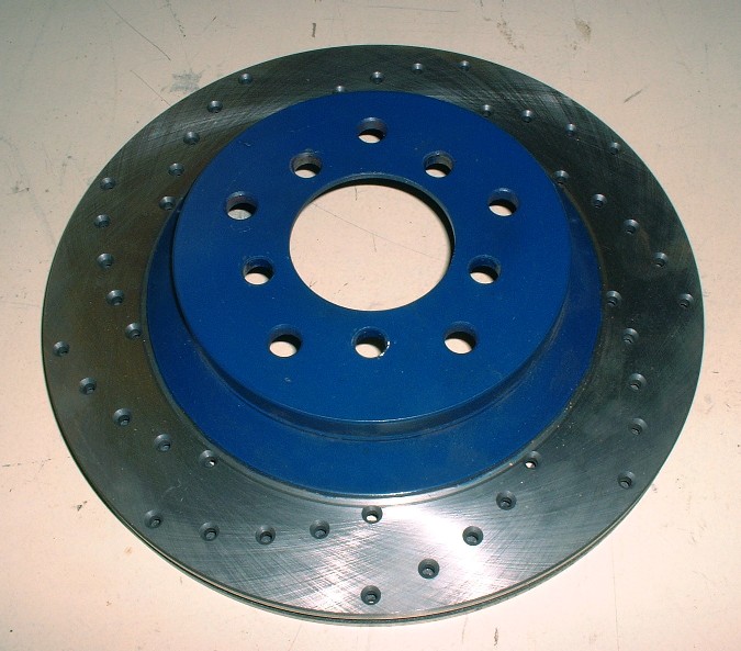
Here’s a completed rotor. I timed myself in case anyone else thought they might like to try doing this. It took me 2.5 hours to set up the jig and complete the first rotor, then each rotor after that took 1.5 hours. It makes for a long day at the drill press!
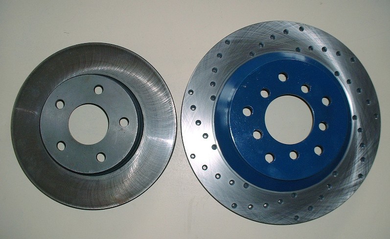
For comparison’s sake, I took a few photos of the Corvette rotor with the Grand Am/Beretta rotor (another popular upgrade). The stock Fiero rotors are 9.7”, the Grand Am’s are 10.25”, and of course the Corvette’s are 12”.
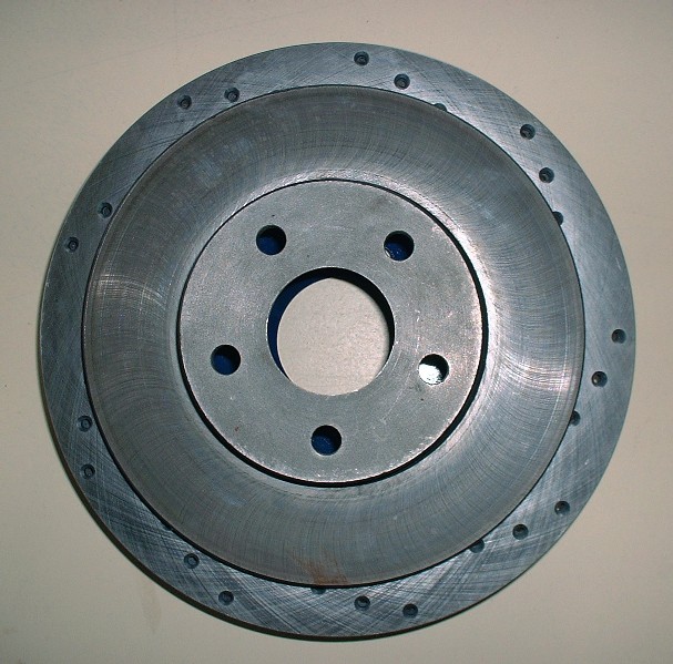
Another view of the GA vs Corvette rotor.
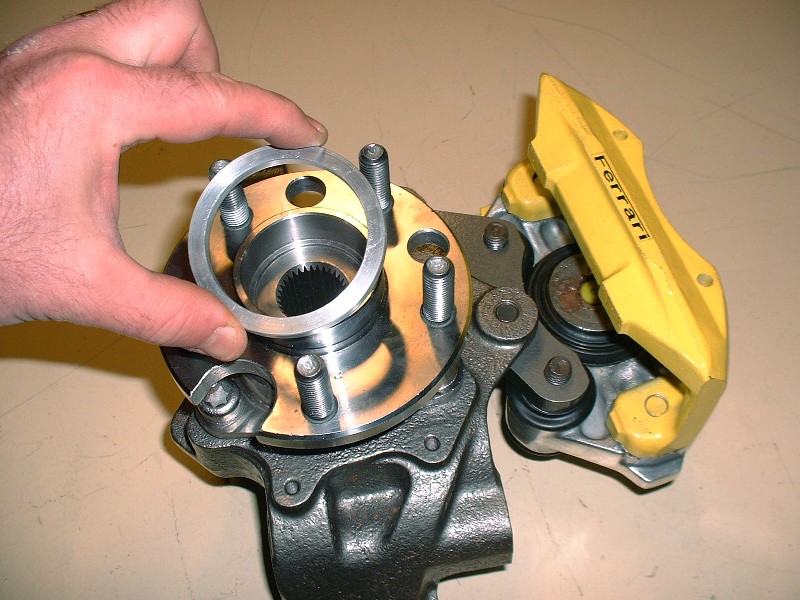
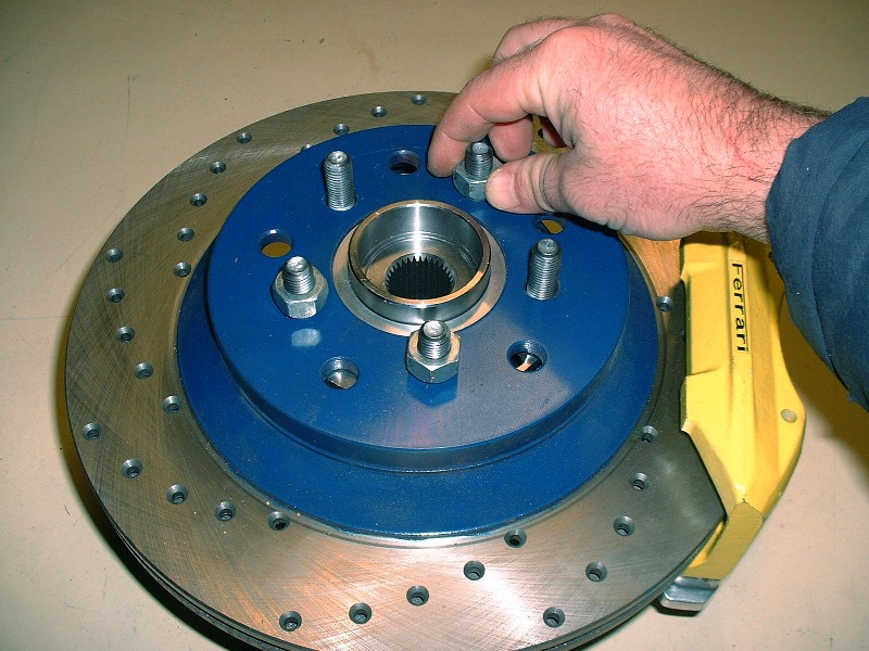
For the Corvette rotor to seat concentrically on the Fiero hub, most people know that you need an adapter ring to up-size the lip on the Fiero bearing flange. I got mine at the same time I got the caliper adapters from Fiero Addictions. To install them, it’s a simple matter of slipping it on to the snout and it’s done, but you have to be careful since there is a front and back side to the ring. The back side’s inside diameter is chamfered to accommodate the filet radius where the snout meets the flange.
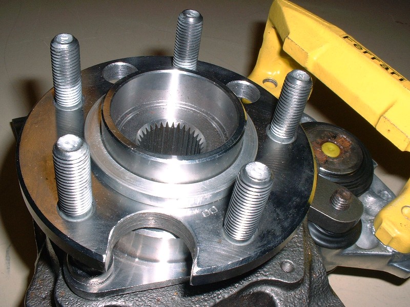
It should sit nice and snugly against the flange like this… if it doesn’t, then there’s a good chance you have the ring backwards or there some foreign debris between the two.
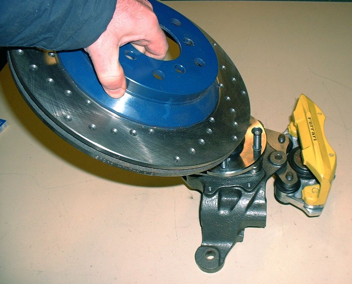
The last thing to do is slip the rotor on. I’ve found that it can be installed with the caliper already on the knuckle as long as the pads aren’t installed. You have to tip it at a bit of an angle though.
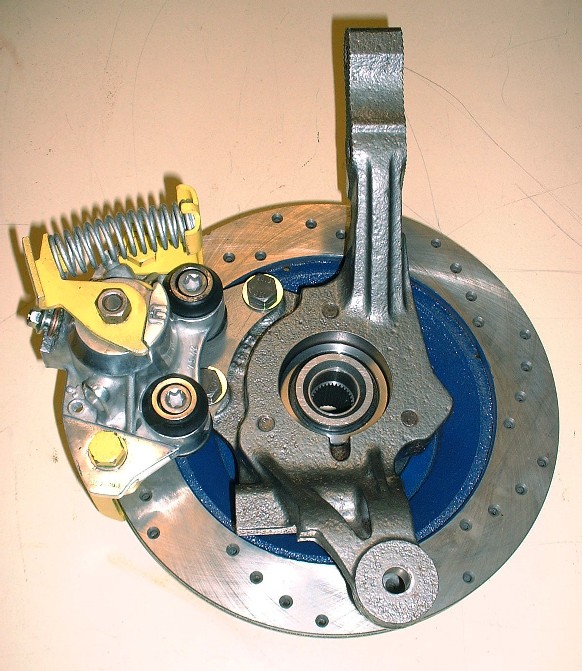
Then to secure it temporarily, I installed a couple lug nuts on a few wheel lugs. Here you can see how the hub centric ring takes up the space between the Fiero hub snout and the larger diameter center hole in the Corvette rotor.
I still need to install the pads, roll springs, and the wire bales, but it’s starting to shape up.
I’m also progressing nicely on my F40 drawings and will soon start working on the N* drawings. I’d like to have them completed before starting the redesign of the cradle. That means I need to stretch out a few more suspension pics to buy time.
Awesome! I do have a few questions if you don't mind that pertain to this. First, could I do this to my grand am brake rotors? And second, does cross drilling actually make a noticeable difference, what is the purpose of them exactly?
[This message has been edited by mattwa (edited 01-29-2011).]
I would suggest checking the balance on the rotors once the holes are drilled. The inner portion between the vanes of the rotor is cast and not necessarily uniform thickness and with this variation you could have removed more or less material from hole to hole. Several of the Vette rotors I have used have some balance weights shoved into the vents to balance them and account for this casting variations within the vane sections.
Thanks doublec4. Matt, you can do this to your GA rotors as well, just be aware that you should inspect the rotors more frequently for cracks that start emanating from the holes. Just Google "cross drilled rotor cracks" images to see what I mean. Some companies now offer dimpled rotors instead of drilling. The dimples are laid out in thte same neat patterns, but they won't initiate any crack sites.
The purpose for cross drilling is mostly cosmetic today, especially on road cars. With older brake pad compounds, the heat generated by braking caused the pad to release high pressure gasses between the rotor and the pad. Without a place to go, these gasses would literally force the pad away from the rotor causing less effective braking. Cross drilling relieved the pressure, but so did modern brake pad materials.
Edit: Good idea fieroguru... I should run them out to the machine shop and get them balanced. I'll post back here with the results.
[This message has been edited by Bloozberry (edited 01-29-2011).]
Well, cptsnoopy and doublec4 figured it out. I haven’t a clue what ArbinShire or fierogt28 were thinking. Weren’t you guys paying attention about the part with the HT Motorsports 6" track width tubular control arms? Or when I mentioned the spacers were for sale? I’m starting to think you guys are just looking at the pretty pictures.
D'oh! I didn't catch that. +1 for doing it the right way!
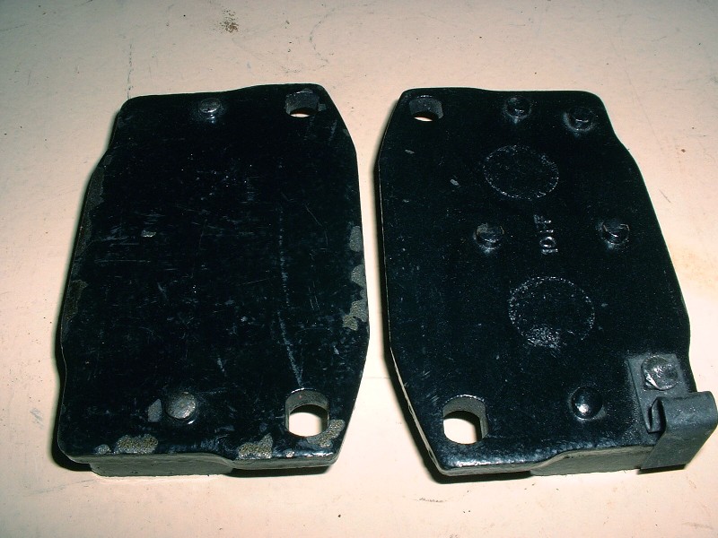
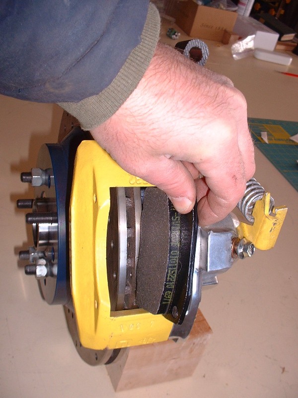
Well I’m running out of rear suspension build-up photos so this will be the last rear suspension post until these parts meet up with the new cradle. I left off the last time ready to install the brake pads so here’s a few pictures covering that aspect. The first one here shows that there are differences between the inboard and outboard pads. The pad on the left is the outboard one and is differentiated from the inboard pad by the lack of the two pegs in the middle of the steel facing seen on the right hand pad. These pegs fit into corresponding dimples in the face of the piston, so the piston must be rotated to have the dimples aligned vertically in order for the inner pad to fit.
When I first tried to install the inboard pad everything was hunky-dorey but when I tried to fit the outer pad into place, there wasn’t enough room even after jimmying the caliper on the sliders to give as much space as possible. At first I thought I’d have to shave the pads down a bit but then got to thinking the piston didn’t look fully retracted. After taking off the e-brake lever and trying to push, rotate, squeeze and use every other possible method of recessing that piston into the caliper some more, I unscrewed the bleeder valve to have a look down the hole. Everything was clean, and by chance, I tried squeezing the piston in further while the bleeder was out and it slid in easily another 3/16”. I discovered that the bleeder valve was screwed far enough into the bore (without the banjo fitting) that it was preventing the piston from retracting fully. Duh!
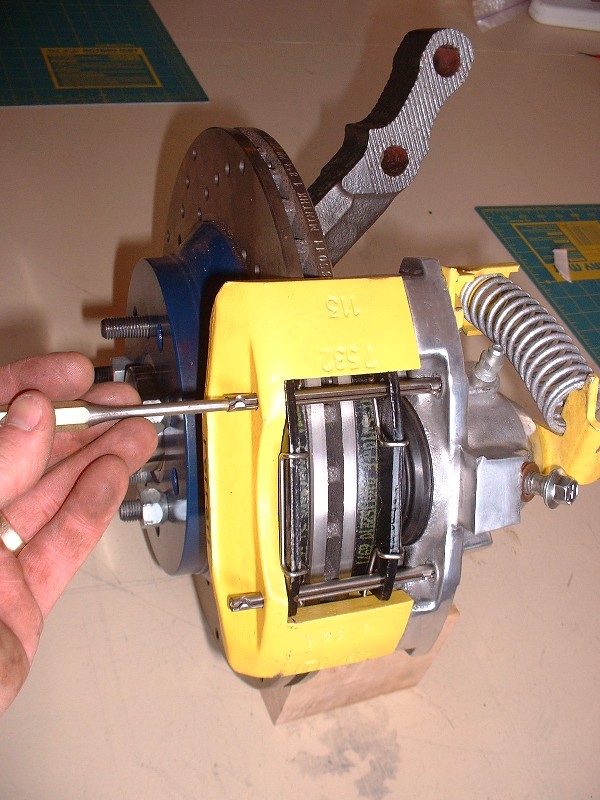
The extra room was all that was needed to slip both pads in with space to spare. So then came the bail wires, and finally the two roll pins keeping everything together. The roll pins are a press-fit into the aluminum half of the caliper so a couple taps with a small hammer and a punch is all that it takes to seat them.
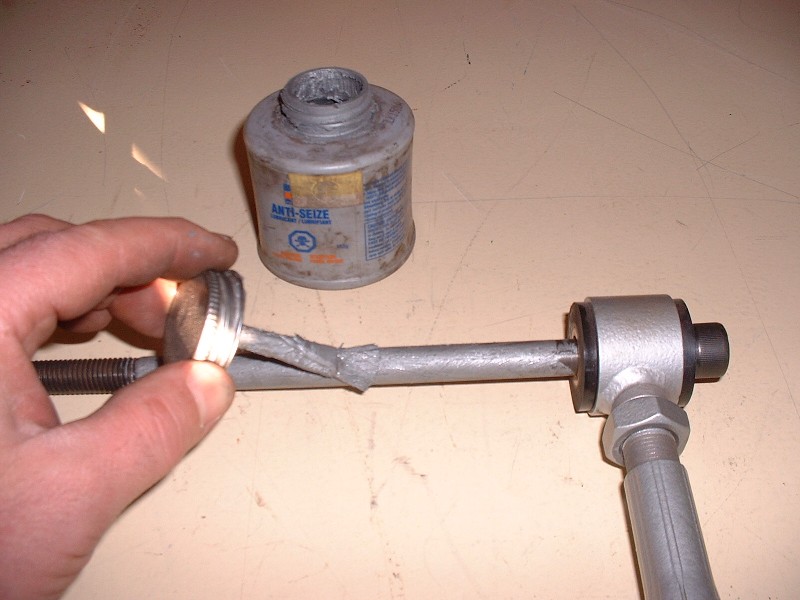
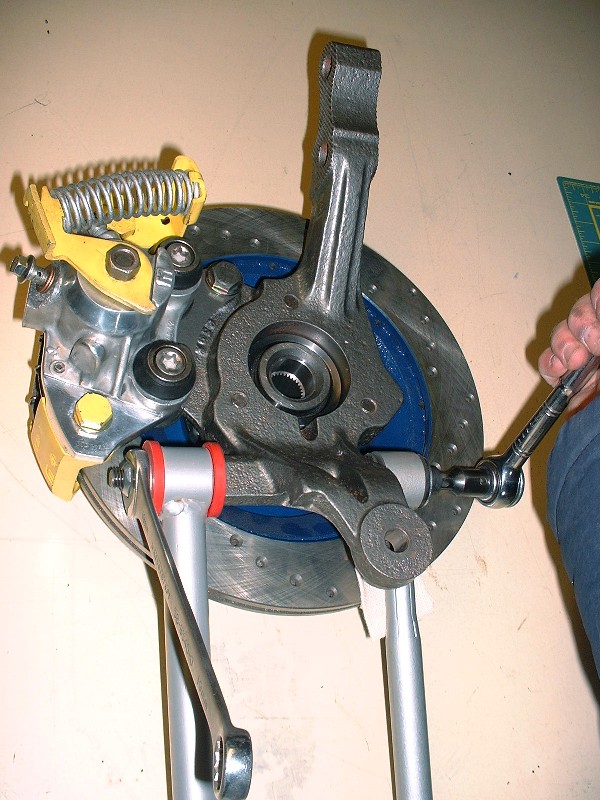
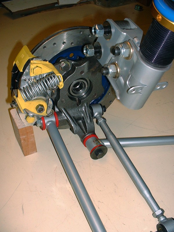
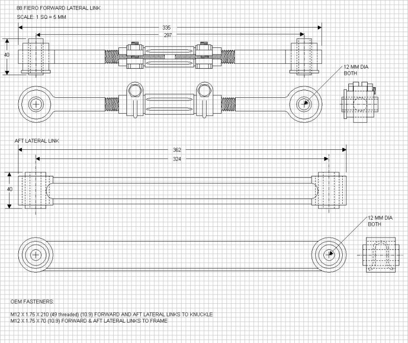
I decided to build up the rest of the rear suspension off the car so next up was installing the two lateral links. On the ‘88’s, they’re held on to the knuckle with a single M12 X 1.75 X 200 bolt passing through a drilled passage in the lower knuckle. This knuckle hole is notorious for becoming out-of-round and allowing some slop in the bolt, causing problems. Mine were still nice and tight; though I blew them clean with the bead-blaster to clean out the little bit of rust hanging around in them. I ordered new bolts in the smallest order quantity possible for these 12.9 grade bolts (a box of 12) for $100. I actually bought them 220mm long since that way I could cut off 20mm for the rear bolts and use the rest as spares for the hard-to-find pre ’88 front upper control arm pivot bolts as well. I greased them up with anti-seize compound before installing them.
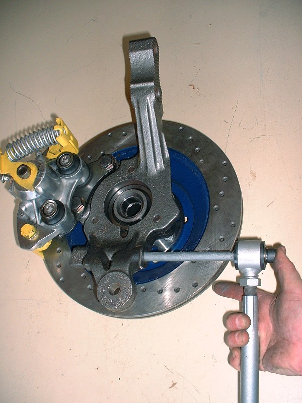
Then slipped the forward adjustable lateral link onto the bolt, then the bolt through the knuckle, and the rear fixed lateral link on the other side.
The nut gets torqued on with 37 lbft first, then turned another 90* for the proper torque. Here I was just getting things snugged up.
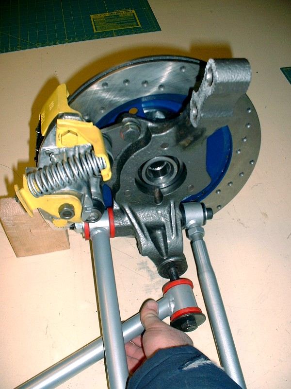
After the lateral links, the trailing link was next. At the knuckle it takes an M12 X 1.75 X 65 (9.8) bolt and nut torqued to 44 lbft. The eagle-eyed among you will notice that in this picture, I’m installing the trailing link facing backwards. No biggie, I just swung it around to face the right way in later photos!
Here’s the LH knuckle with all three links attached and again, the eagle-eyed among you will notice that I installed the RH trailing link on the LH knuckle… the telltale sign is that the grease zerk fittings should be on the bottom where they’ll be accessible. I’ll change them around another day.
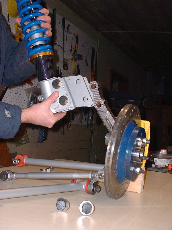
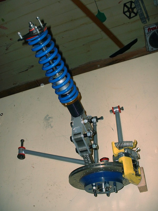
The last item to be installed was the strut. I’ll probably need to remove them later to install the suspension in the car, so I only installed them loosely for the pretty pictures. It’s held on to the top of the knuckle with huge M16 bolts.
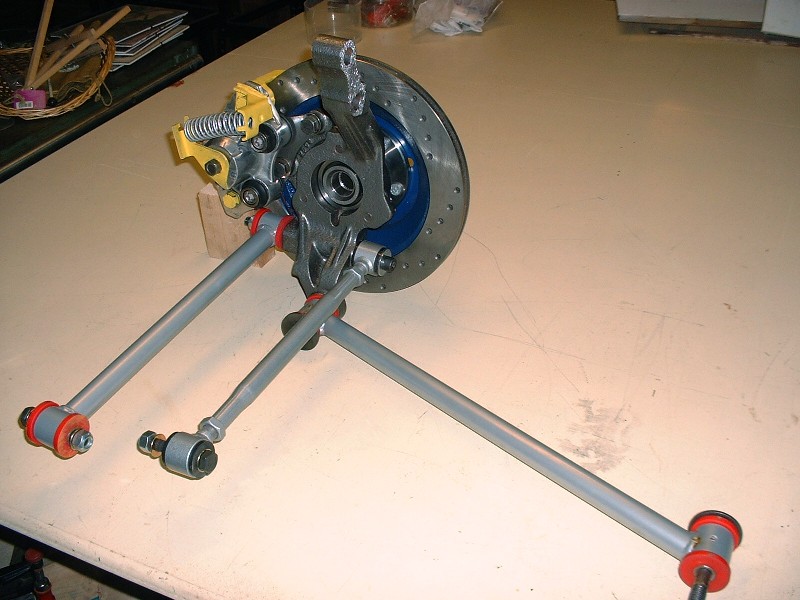
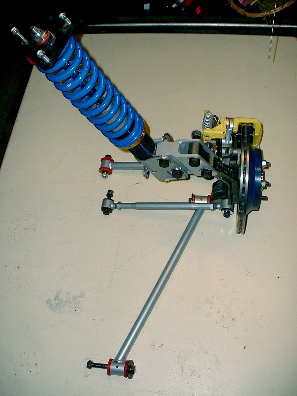
Here’s a close up of all the links attached to the knuckle:
And finally a couple shots of the whole rear suspension for the LH side. I should weigh it, but I’m afraid of what the scale may say!
Your attention to detail is inspiring! I find myself taking my time more often on my winter projects to get things done right. My skill level is nowhere near yours though, but hopefully my results won't be embarrassing at least.
This is my favourite build thread, partly because of the regular updates! Keep it up..
You will want to turn those adapters on the struts over so the strut hangs lower than the knuckle mount. The 355 body kit you have will want the frame quite a bit lower to fill the wheel well properly so having the adapters your way will raise the frame compared to old not lower it. The other way allows for more strut travel compared to your orientation.
Thanks BtotheB (..must be short for "Brad to the Bone" ). Have you got a thread started yet? Canadian winters are perfect for spending long dark days detailing away at things!
For Don: Thanks for pointing out the strut adapters should be turned the other way... I'm not sure I would've clued in on that, but it makes perfect sense. I don't want to have to dial out any more height to the suspension than I'm already having to deal with!
For Tinkrr: The bolt length is another good question since I had overlooked the sway bar until now. I'll check it out later today and report back whether they're long enough or not, and post the details about what dimension bolts are needed. Good eye!
Since you are running poly, I'll recommend that you put a jam nut behind the nut on the long bolt through the knuckle. Many people found that the poly causes the crush nut to work itself loose, even when torqued properly. Even a slight loosening of the nut will cause the toe to move a lot.
Thanks for the suggestion Fierobsessed. Do you still think jamb nuts are required even with prevailing torque nuts (lock nuts)?
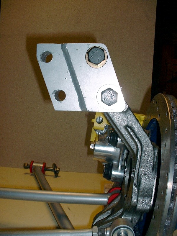
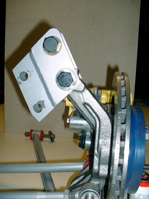
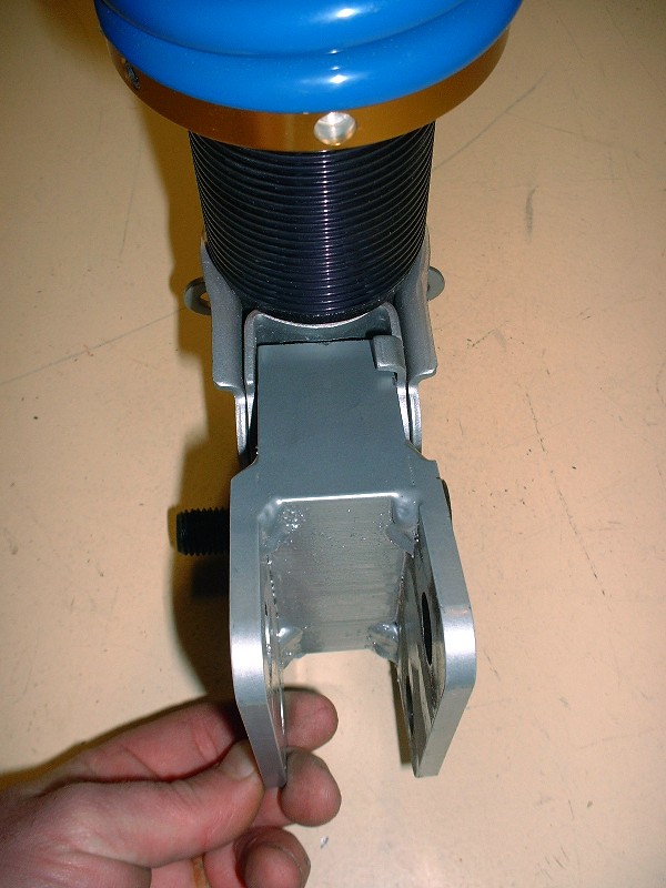
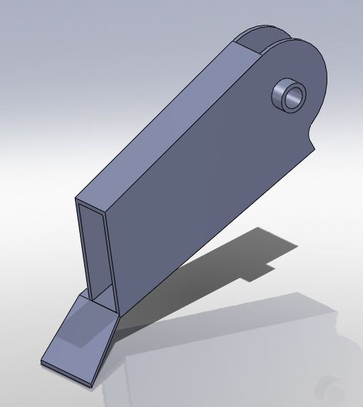
Well Don, I played around with the strut adapters like you suggested and something just doesn’t seem right with them turned the way you suggested. I’m not saying that you aren’t right, but it just doesn’t look like these adapters were made the same as yours… have a look. This is what the adapter looks like on the knuckle with the adapter on the original way I had them:
And this is with the way you suggested. It just looks awkward.
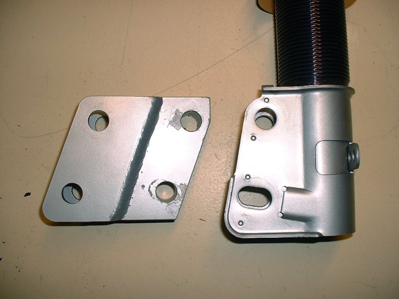
And this is the orientation when installed on the strut the way I originally had it:
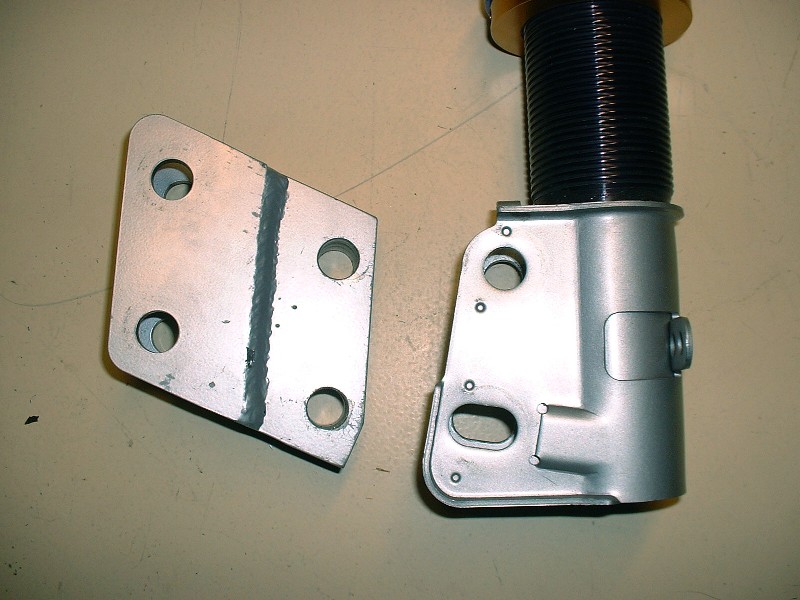
…versus the way you suggested:
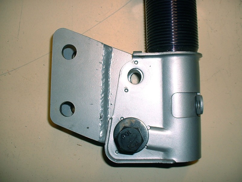
Beyond the optics of the two orientations, when I tried to install the adapter to the strut the way you suggested, I ran into interference problems. Here’s a picture to show what I mean… I couldn’t get the upper holes to line up enough to get the bolt through:
The interference is between the top of the adapter and the strut body. I would probably have to grind off 3/16” or so off the top of the adapter to rotate it far enough to get the holes to line up. To me, it just doesn’t make sense to install it your way. Installing it the original way I had it won’t raise the car in the rear like you thought. Perhaps one of the photos in my earlier posts gave that illusion, but the adapter will line up straight across, neither raising nor lowering the rear.
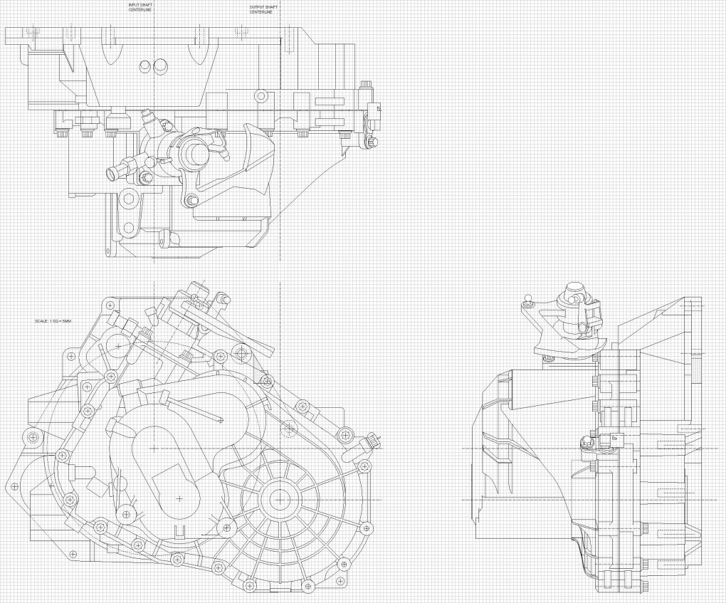
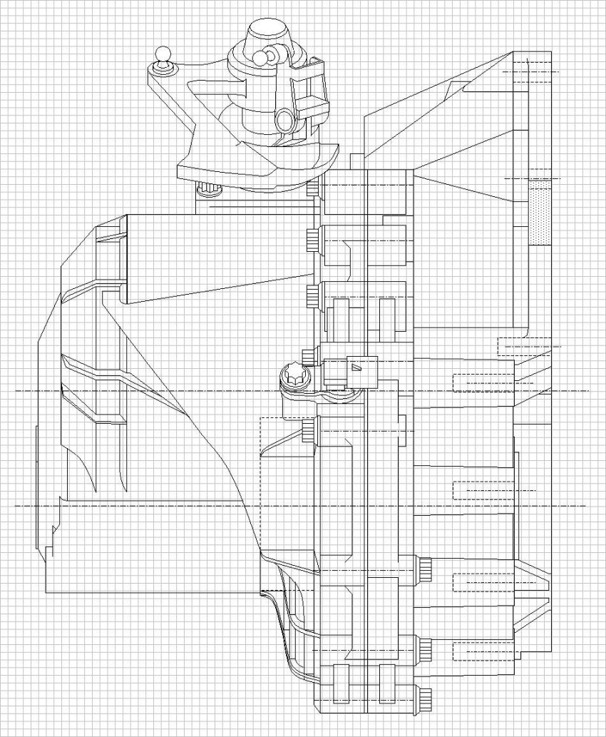
So then, on to new things. I’ve finally finished entering the dimensions of the F40 transmission digitally to help me redesign the cradle. Before going through this trouble, I searched far and wide on the internet, at dealerships, machine shops, etc, and made countless calls to GM trying to find someone to release scale three-view drawings of the F40 and the Northstar to no avail. For a while, I thought that I would get something from GM Customer Services, but at the last moment they said they weren’t permitted. Rats!
So here’s the fruit of far more hours of labor than I dare to admit. Each square represents 5mm. I’ll post high resolution drawings of the transmission when I’m finished working up the cradle drawings. It would be nice if Cliff could create a section on the forum for reference drawings like this. Currently I’m working up the rear knuckles, trailing and lateral links too. So here’s the three view… admittedly low rez to get PiP to accept it:
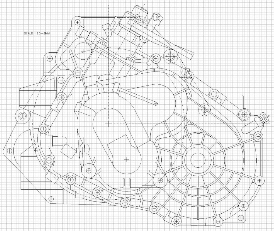
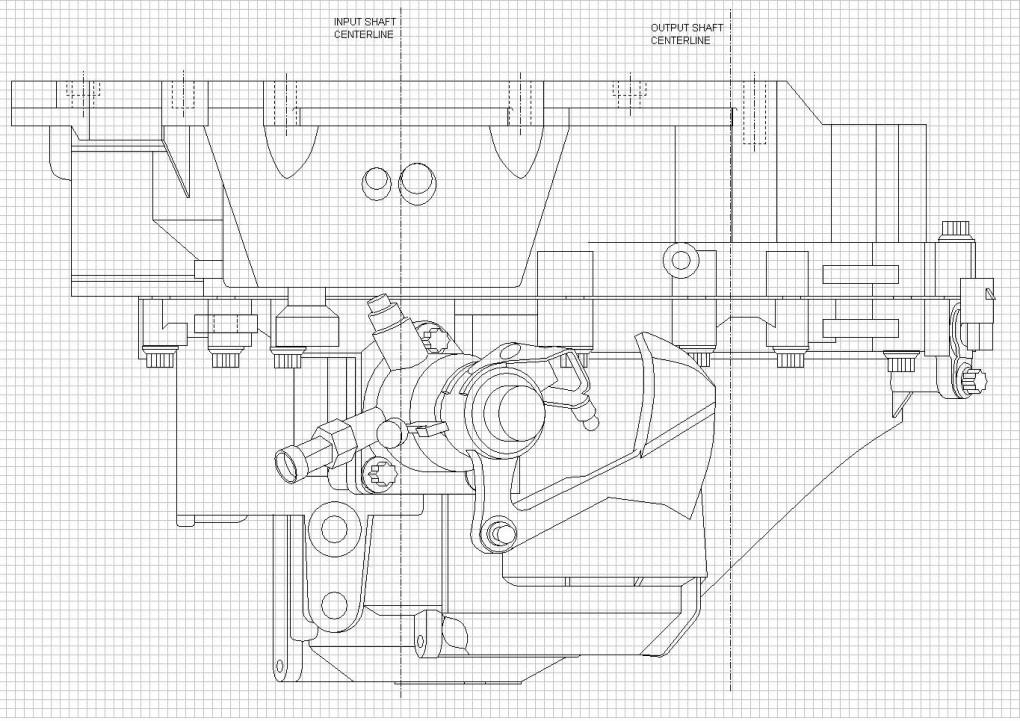
And here are some higher resolution pics of each view separately starting with the end view:
Truly a work of art Blooz! I wish I had the patience - and talent to get to your level of attentoin to detail. Very nice work you are doing. I am truly amazed. I'm pretty sure I said this somewhere else in the thread but I'll say it again. Thanks for sharing your hard work with the rest of us.
Originally posted by Bloozberry: Do you still think jamb nuts are required even with prevailing torque nuts (lock nuts)?
Yes, the issue is that even nylock, crush nut or lock nuts CAN be rotated loose, and poly loves to try to spin the underlying washer, causing the nut to free up. A Jam nut will never allow this. Also, if you look at factory bushings, the sleeve in the center has teeth, one side jams into the knuckle to lock the sleeve to the knuckle, the other side locks the washer to the sleeve. So as long as the bolt is torqued properly, the whole assembly acts as one piece. Poly on the other hand, has no teeth on the sleeve, and the bushing has a good amount of friction with the washer. So it's bound to happen from time to time. On my car it manifested itself as heavy toe changes when going on and off throttle. The rear was quite noticeably kicking out when I got on throttle.
If you can install those strut adapter upside down from your original method, you would lower the rear by the distanct between the bolts.
On traditionally lowered 88's, it is pretty easy to bottom out the strut internally... especially with heavier engine swaps. Flipping the upper strut bushing (at the strut tower) helps some by moving the top of the strut shaft up about 1" and your adapters moving the base of the strut down could help even more.
I would love a copy of your F40 drawings if you are giving them out... fieroguru@lycos.com
I see what you mean on the adaptors. I would say I am 100% wrong and you need to put them back the way you had them. I made my own but when I saw the adaptors from others the strut always looked lower. In talking to others, they also said that the adaptors lowered the strut down. The pics you show clearly will not work the way I suggested so my apologies for giving you more work than you already have.......
Thanks for your kind words there Katatak, and for the advice Fierobsessed, 'Guru, and 355. I am now seriously thinking about redesigning those strut adapters to take advantage of idea to regain some strut travel. That's something I would probably not have thought of on my own.
Well it’s been two weeks since I last posted an update here, but that’s not because I’ve been slacking off. I’ve been busy entering more digital drawings into my computer, saving lots of money not having to heat my shop much this winter.
If you’ve been following along, I realized early on that to design a new cradle for the N*/F40 combination would be silly if I didn’t take advantage of the opportunity to study if improvements were possible as well. The problem with improvements is that you need to have a baseline from which to compare whether your modifications are indeed better or not. It sounds easy, but in reality, none of the Fiero engineering or technical data was released as far as I’m aware, so baseline geometry information remains a mystery to most of us. I hope to fill a little of that black hole by reverse engineering the drawings for the stock configuration as a starting point.
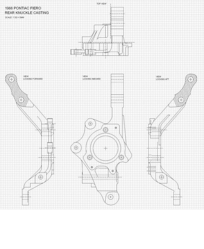
To start the ball rolling, I’ve decided to draw out all of the stock suspension components starting with the ’88 rear. I admit that the accuracy of my drawings is a limiting factor, since most measurements have been taken with calipers, rulers, bubble levels, and squares, not lasers, but they should be good enough to make comparative assessments for most suspension tweaks nonetheless. I also hope to use the drawings later on to create a visual guide to help people determine whether different diameter, width, and offset wheels will interfere with different combinations of coilovers, OEM springs, lowering, etc. (It would be nice if PFF had a repository for such reference material once it's done… hint hint Cliff.) But for now, I have a more selfish goal.
So for starters, here’s the ’88 rear knuckle:
The rear strut assembly proved to be a bear to draw out accurately, but I think I finally have it reasonably precise. The two biggest issues I ran across were the fact that the OEM strut I have to work with, has a worn out top bushing which I only realized much later. This skewed many of my measurements since the top hat was sitting crooked. I thought it was supposed to be like that. The other issue was that since I drew it from the bottom up, I originally assumed that the spring's axis was aligned with that of the struts, only to find that the top hat would not line up with the top of the spring once I got to that point. It turns out the spring is actually offset towards the center of the car on the strut, presumably to give more room for the rear tire. Here’s the finished product in the uninstalled height configuration:
The last thing I drew out was the suspension links. They weren’t difficult, luckily, since by that time my eyes were starting to get tired of focusing two feet away at my computer screen for the last two weeks. These are the lateral links:
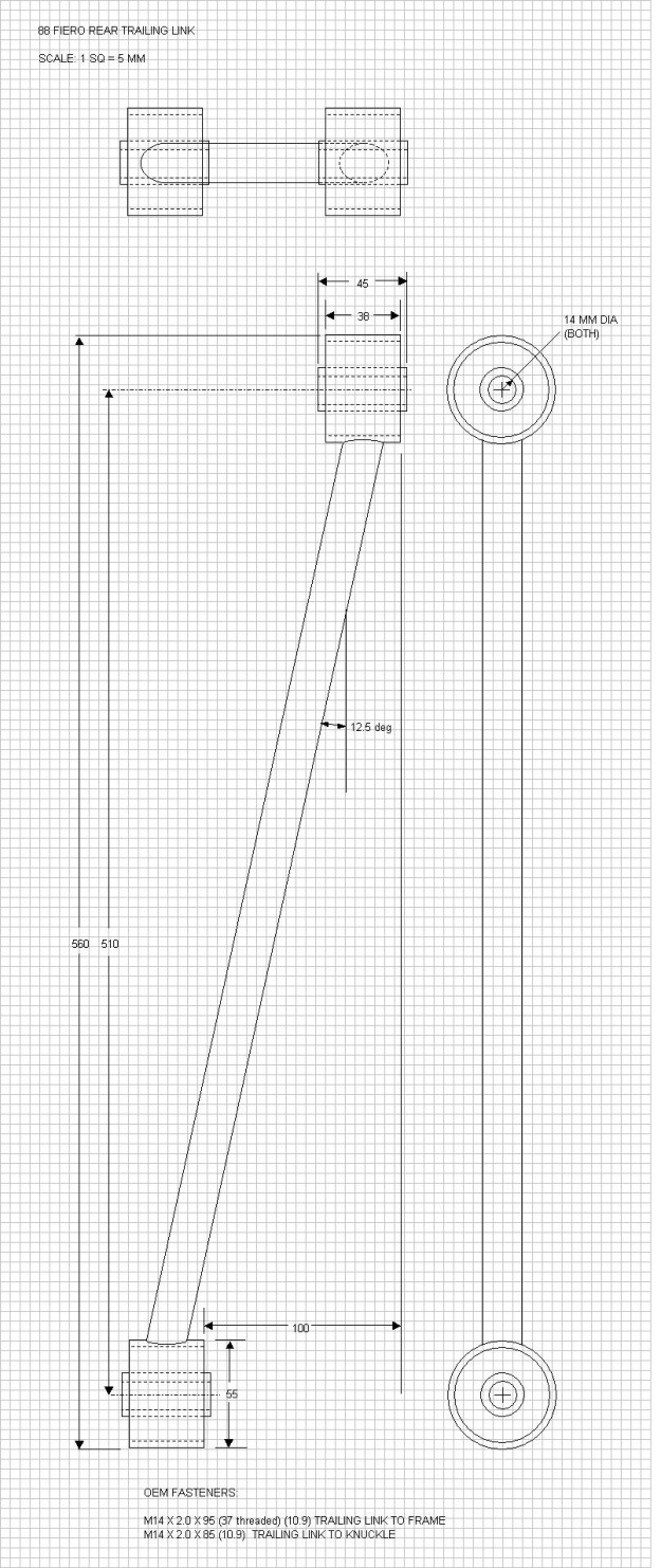
And here's the trailing link:
I’ve already combined all of these components onto a master drawing combining the earlier cradle and the F40 tranny drawings. I need to determine a few things yet like the height of the spring at curb weight which means trying to determine the height of the underside of the strut tower mounting surface in relation to some fixed reference point on the cradle. The chassis alignment data in the service manual is lacking in this area. That will be a challenge to measure I think, but I’m determined. More to come.
As always, I appreciate your feedback doublec4 and fieroguru . You guys are doing some amazing stuff in your own respective threads too. It's great to see people stretching or contributing to the envelope of Fiero knowledge 23 years after its demise.
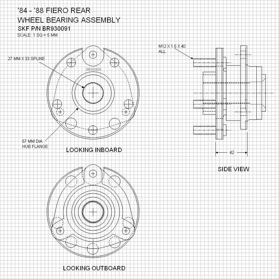
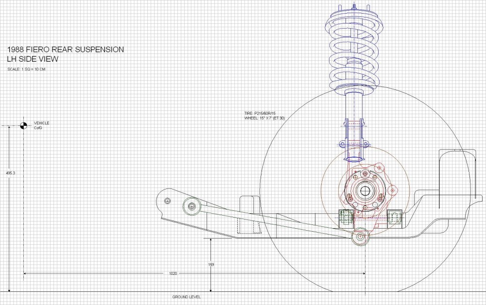
Moving right along, I completed drawing the final suspension components to allow a digital reconstruction of the entire rear suspension system. The last pieces were the wheel bearing assembly (which is identical to all year Fiero's), the brake rotor, the 15" x 7" (ET 30) wheels, and P215/60R/15 tires. I didn't bother drawing out the wheels and tires in great detail nor separately, but chose instead to add them to the master drawings. So for starters, here is the rear wheel bearing assembly (this is SKF part):
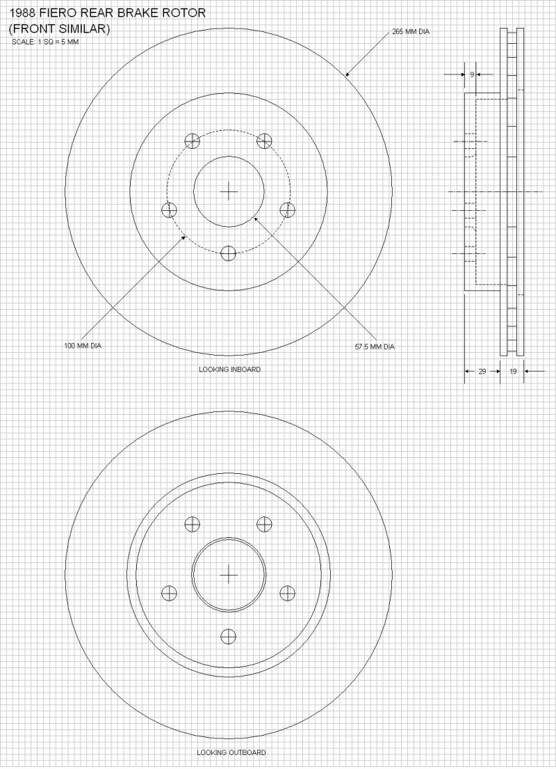
And here is the rear rotor ('88 rotors are identical fore and aft):
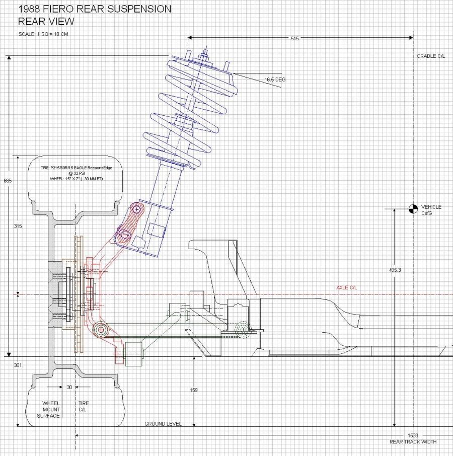
With these last parts drawn out, I combined all the previously drawn parts onto a single set of drawings depicting the rear suspension system in it's entirety. The precise location of the top of the rear strut wasn't an easy measurement to take, but I cross-referenced the dimensions from my own '88 project car chassis and those taken from an '88 GT stored here for the winter. Here are some sources of info regarding some of the dimensions:
1. the location of the center of Gravity (CofG) of the car in the vertical plane was taken from Road & Track Magazine, Sep 1983, in the article Pontiac Fiero Introduction from the Technical Analysis section. Although this was specifically for the '84 four cylinder car, I assumed the height of the CofG didn't change much, of at all with the introduction of the V6;
2. the horizontal location of the car's CofG was calculated based on the reported front to rear weight distribution (47%:53%) from various magazine sources testing cars with the V6, namely: Road & Track Oct 87, Automobile Magazine March '87, and Car & Driver Feb '86.
3. the ride height of the car (ie ground clearance of the cradle) was a rather fuzzy measurement to take empirically given the variables (tire heights and spring sag to name two.) So I referred to the trusty ’88 service manual but found problems there too. It gives the ride height in a table on page 3-16 but the accuracy of the numbers is contestable, since the ride height doesn’t seem to change despite three different listed tires sizes. There is a 4.5 mm difference in the radius between the tallest tire (215/60/15) and the shortest tire (195/70/14) listed, yet the ride height remains the same according to the manual. To get even more conflicting info, I referred to various magazine articles which stated the ground clearance as anywhere between 5.4” to 6.0”. In the end, I decided to let the ground clearance set itself by drawing the lower lateral links parallel to the ground, and add the P215/60R/15 tires digitally onto the hubs. The dimensions for the installed tires came from two different sources averaged out: the stored ’88 GT with brand new Goodyear Eagle Triple Treads, and my own ’86 GT with 1500 miles on Goodyear Eagle ResponsEdge tires at 32 PSI. Final clearance = 6.25"
I think that’s all that needs to be explained regarding the sources of information contained in the drawings below, but if you have doubts or questions, please don’t hesitate to ask. I would rather have someone point out an error than continue promulgating it. The next step is to determine the key OEM suspension characteristics such as the instantaneous centers, the roll center, percent anti-squat, etc. I’m armed with Herb Adams book Chassis Engineering, the internet, and a bag of Doritos to help refresh me in that department For now though, here's the top view:
This makes me love you. No, I mean it. I've been looking for drawings/measurements like this, but am far too lazy/incapable to do them myself. A plus to you, kind sir.
Bloozberry, I had sent you an email a week ago, I am just wondering if you received it. If you didn't, I am hoping you would not mind sharing your hard work with me, I just finished up my degree, giving me much more free-time to take your drawings and create some solid models of your drawings.
Hey, thanks there aaron and dobey (although I won't believe that you love me aaron until I see a box of chocolates )! Even though drawings aren't as exciting as pretty pictures, I knew some people wouldn't mind a quick detour into the nuts and bolts behind the suspension.
Enough drawing and more working!! I wanna see this baby done! Have you ever watched a movie at 30 second incriments over the course of 3 years? THATS WHAT THIS IS LIKE!! Lol but the drawings are super helpful (not for me, I have an 84, 85 and an 86) I'm amazed by how paitent you are with this. You don't rush or get overanticipated. That is why I check this build everyday for updates. Keep them coming! Even if they are small. Either way your builds are simply amazing.
As a person who works with CAD every day, I'm really impressed with your drawings. I can't believe you did that all the "old fashioned" way, measuring manually, instead of using a Faro arm or laser scanner or similar. Must have taken a long time, you are extremely patient! Are you doing line drawings or making solids of these? If you can save the CAD files as something in a 3D format (ideally, 2D works if that's all you have), I'll be sure to give them a home on the web for all to use and share. I've been contemplating making a tubular rear cradle on an '88 for Northstar guys as well, so maybe we can join forces and brainpower. You're ahead of me, for sure, but like you said earlier, a few viewpoints can result in better details you wouldn't think of on your own.
I started on the solid modeling of the cradle, this is going to take the longest to make, there are many profile changes and obscure geometries to model, but I'm getting more familiar with the different solid works features I haven't used much in the newer versions.
Dhobbs, I know exactly what you mean… I’m getting cabin fever sitting at this computer and am dying to get my hands dirty again.
Nashco: Thanks for the compliment. I wanted to create the drawings in a software package that’s not only available to the masses, but one that everyone operating Windows already has. My drawings were created using Microsoft’s drawing toolbar which can be found under View, then Toolbar menus. I open up an MS Excel file, force the grid lines to squares, then use the drawing tool to create the illustrations. They’re vector drawings so they’re fully scalable and I plan to give everybody access to them eventually. FieroWannabe is one of several who have offered to convert them into 3D as you can see from his latest post. I appreciate your offer to host the source files on your website but I would prefer to have them here directly on PFF somehow. As for providing constructive input, I’m planning on going through the design exercise right here in the thread to get feedback from anyone who’s interested, so you’re more than welcome to join in… I look forward to your contributions!
Well after this post, I think I’ll have finally done all I’m going to do to map out the OEM rear suspension (only the die-hards will stick with my thread after this one). I’ll be the first to admit that I’m no suspension guru and I’m more than a little wet-behind-the-ears when it comes to suspension dynamics, so please don’t be too harsh on me if I get something wrong. My objective here was to learn something new and try to understand what the effects of HT Motorsports extended control arms would be on my car and improve the characteristics if possible.
I bought what I thought would be a great reference book, Herb Adams Chassis Engineering which is highly regarded by many as the “suspension bible”. Rather unfortunately it was a serious letdown for me on several counts. The rear end suspension section was written with its primary focus on live axles and had very limited analysis of independent rear suspensions. With the vast majority of front-wheel drive cars today using Macpherson strut geometry, I expected there would be a great section devoted to them for front suspensions that I’d be able to apply to our unique cars in the rear. Much to my dismay, the only drawing in the book of a strut type suspension is improperly drawn, poorly explained, and incorrectly labeled. Finally, the book is very thin on details regarding how to calculate many of the interesting characteristics of suspension geometry. Instead, the reader is encouraged to buy a suspension software package and let the program do the work. Not exactly what I expected. So most of what I learned recently came from gleaning tidbits of information from many, sometimes contradictory, sources on the internet ( oh yay).
I decided for my most basic analysis of rear suspension geometry, I’d look at five things: swing arm lengths; roll centers; camber changes; toe changes; and anti-squat. Each are discussed separately below, so your own bag of Doritos might come in handy if you plan on sticking with me.
Swing Arms
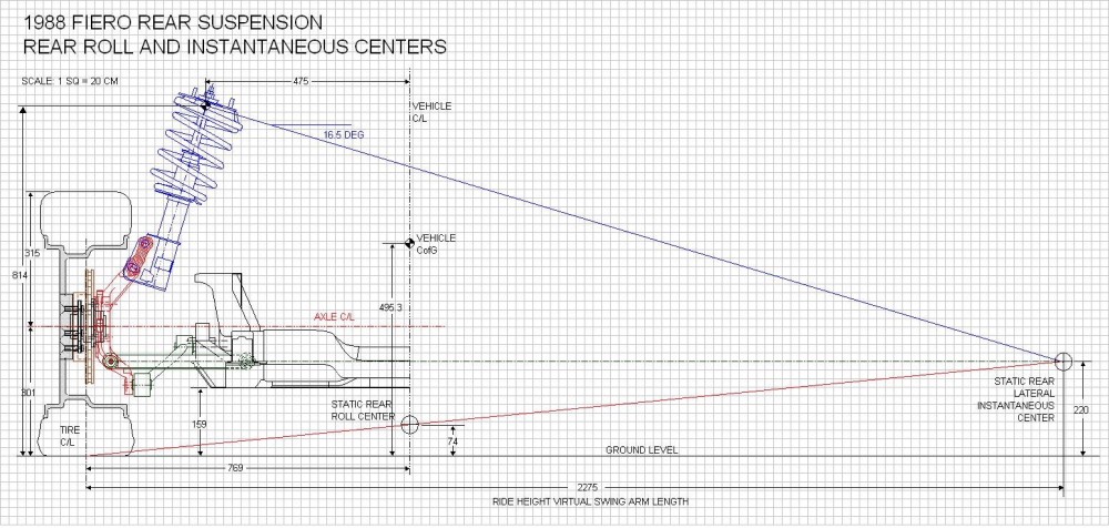
Understanding swing arms is easy: it’s basically figuring out that the wheels move up and down as though they’re attached to much longer control arms than what they look like. On the ’88 Fiero, which has a Chapman strut rear suspension, the wheels actually move up and down (as viewed from the back) as though they were on levers 7’5” (2.275 meters) long… a far cry from the paltry 1’8” (324mm) long lateral links connected to the knuckle. The first drawing below shows how the virtual swing arm is measured on an '88 Fiero. On a Chapman strut suspension, two lines are drawn: one at right angles to the strut centerline starting at the upper strut bushing (the upper blue line); and the other line through the two pivot points of the lower control arm (the green dashed line), until they intersect way off to the extreme right of the drawing. The intersection is the location of what’s called the lateral Instantaneous Center (IC) for that rear wheel. The length of the swing arm is the distance as projected on the ground from the IC to the centerline of the tire patch. This means that the wheel initially moves through an arc as though it were connected to a lever that pivots at the IC. As you’ll soon see though, the IC moves around as the suspension compresses and extends.
Roll Center The second thing that can be found once the IC and swing arm are determined, is the rear Roll Center (RC) of the car at ride height. The rear RC is the point about which the center of gravity of the car wants to roll around at the rear. To find the rear RC, all you do is add the red line shown above starting at the center of the tire contact patch and intersecting the IC. Once that’s done, wherever the red line crosses the centerline of the car, that’s where the rear roll center is located. For the Fiero, it’s 74 mm (2.9”) above the ground with the suspension at ride height. According to Herb Adams, “Most successful cars have the roll center height between 1.00 inch below the ground, to 3.00 inches above the ground” so 2.9 inches seems acceptable.
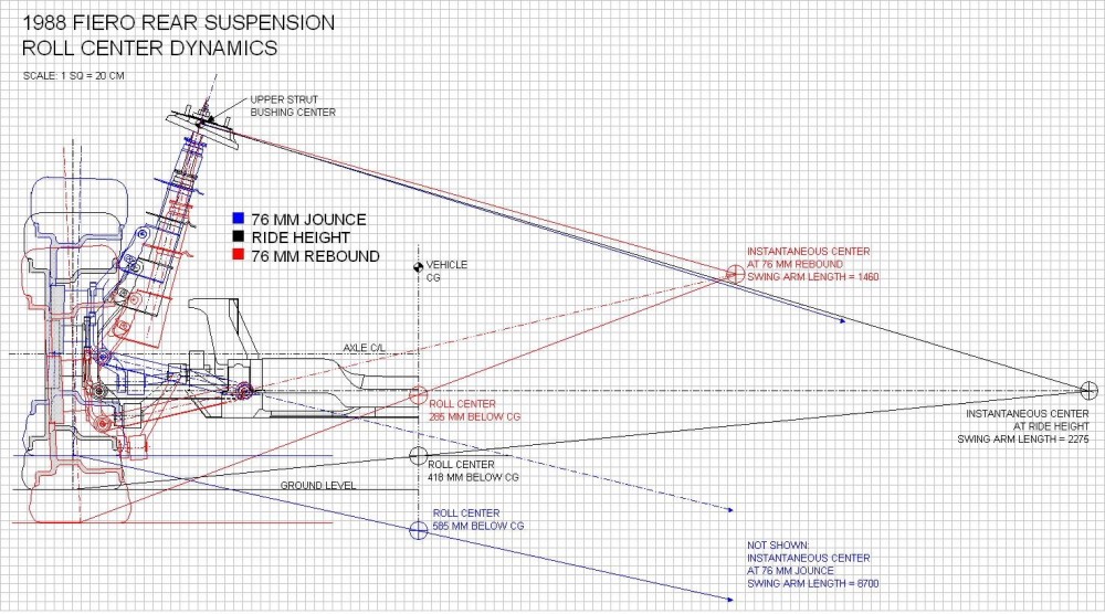
Here’s where it gets a little more complicated, and the drawing a lot more busy. As mentioned earlier, the instant center for the rear of the car changes location since one of the lines used to determine where it’s located, is drawn through the lower control arm. As the lower control arm pivots through its range of movement, the IC and RC will move around with it. To see the effects of that when the ’88 Fiero suspension goes through 3” (76mm) of jounce (blue lines), and 3” (76mm) of rebound (red lines), I replicated the components, rotated them, and added them to the above drawing to create the drawing here:
I know it’s a mess of lines, but it’s a lot simpler if you focus on one color at a time. Starting with the blue jounce lines that angle towards the lower right hand of the drawing and end in arrows, the swing arm length gets so long that I had to calculate its length because the software wouldn’t allow me to make a drawing that large. It went from 2275mm at ride height to 8700mm! Using the same method to find the new roll center as above, the RC drops to below the ground level and further away from the car’s center of gravity by (585mm - 418mm) = 167mm or 6.57” as compared to the location at ride height. A better design would keep the distance between the RC and CG more constant throughout the suspension travel according to Herb Adams. He also says that “reducing the distance between the RC and the CG will reduce roll angle, which leads many racers to want to raise the RC. But a higher RC causes jacking effects and erratic suspension movements”. Instead, “…roll angles can be controlled with stabilizer bars, front and rear, so there isn’t the need for the roll resistance that a high RC gives.” Keeping the RC at a constant height is more important than reducing its distance to the CG.
In rebound (the red lines) on the other hand, the swing arm is reduced fairly significantly causing the roll center to rise up towards the center of gravity by (418mm – 285mm) = 133mm or 5.24”. This would happen in one of two circumstances: either after going over a big bump and the car getting airborne, or on the inside wheel while going around a fast corner. In either case, the wheel is unloaded dramatically and from what I could glean, has little effect on the car’s handling in this extreme case.
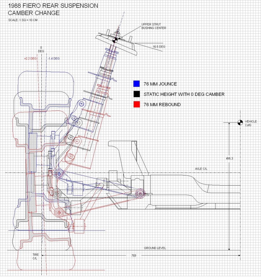
Camber Change The third on the list of basic suspension characteristics is the amount and direction that wheel camber changes as the suspension moves through its range of motion. Camber is the tilting of the wheel vertically as viewed from the front or back of the car. As a vehicle turns a corner, the body rolls toward the outside of the turn and the weight transfer compresses the outboard suspension. If the wheel were to stay perpendicular to the side of the car when it did this, the tire contact patch would tilt away from the pavement onto its outside edge and lose cornering grip. A good suspension design causes the outboard wheel to tilt progressively more inwards at the top to keep the tire contact patch in full contact with the pavement as it compresses. This is called camber gain under jounce. The reverse is true for the inside wheel. Herb Adams book states that one of the main limitations of a Chapman/Macpherson strut suspension is that the design is inherently poor at providing decent camber gain.
To see the effect of suspension compression on camber, once again, the rear view drawing comes in handy, with a few notes to observe: I don’t show the cradle roll angle in either direction for clarity’s sake; and at ride height (black lines), I drew the wheel with zero preset camber, when in reality, the alignment specs call for minus 1 degree:
From the tilting of the wheel centerline you can see the OEM suspension does indeed react the way it should, that is: the wheel gains 1.4 degrees of negative camber under compression and 2.2 degrees positive camber under extension. In Herb Adams example, his car gained 2.7 degrees in negative camber at 3” of compression, and was basically at zero camber gain in extension. For the best traction around a corner, the camber change should come close to matching the angle of body roll to keep the tire perpendicular to the ground. Without a stabilizer bar (anti-roll, swaybar, whatever) to help to keep the body roll angle down, it appears our little cars would suffer rear cornering power loss due to the limited rear camber gain.
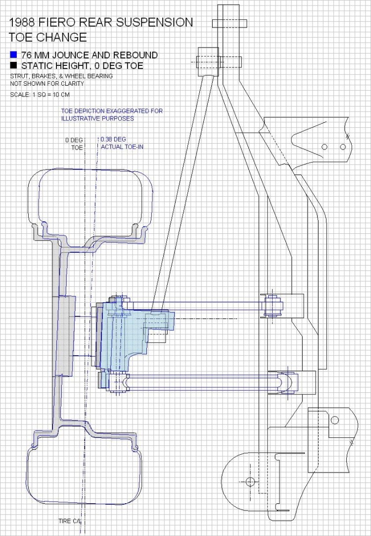
Toe Change The fourth characteristic I wanted to study was the change in rear toe as the rear suspension moved through its arc or travel. Toe is the amount of rotation the wheels take on in the steering axis as viewed from the top of the car. To quote Herb Adams “ Bump and roll steer are really the same thing. What they refer to is the amount and direction that each rear [wheel] might cause the car to steer as it moves through its travel. Even slight changes in the alignment of the rear [wheels] will cause big changes in the direction the car will go. The preferred design characteristics are very little roll steer, and if there is any, it should be in the understeer direction.” For an independent rear suspension “…roll understeer is obtained by having the wheels toe-in as they go up into jounce.”
To visualize what happens on the ’88 Fiero rear end, I used the top view of the suspension drawings I made earlier. To ensure that the rear wheels toed-in on the Fiero under jounce, GM made the forward lateral link shorter than the aft link. The reason this works is because the shorter forward link will cause the front of the knuckle to pull inboard faster than the longer aft link when they are pivotted upwards. I redrew the two lateral links as they would be seen from above, once their angles had been raised to the 3” jounce position (lines in blue). The difference in their effective lengths was only 1.0mm so I needed to calculate the change in toe using basic trigonometry rather than by trying to measure it on the drawing. I grossly exaggerated the change in toe on the drawing to demonstrate the effect of jounce. The actual toe change is about 0.38 degrees toe-in, which seems to meet the requirement stated by Herb Adams above.
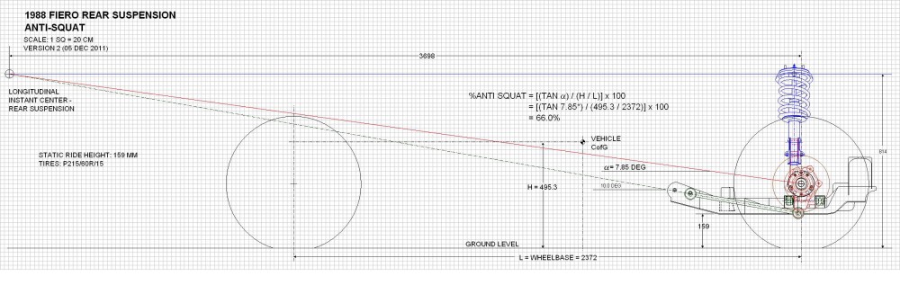
Anti-Squat Finally, the last characteristic to be studied is anti-squat. Squat is the tendency for the rear of the car to lower as the weight transfers rearward under acceleration. Anti-squat is a suspension characteristic that opposes this tendency, increases rear tire loading, cornering power, and traction available for acceleration. With a live axle, the suspension can be designed to provide 100% anti-squat, but unfortunately for us, the use of an independent rear end limits the amount of anti-squat to around 25%.
Calculating anti-squat for an independent rear end is one area that Herb Adams book didn’t cover very well in my opinion. After a lot of internet searching, I finally found a formula that allowed me to calculate it for a Chapman strut rear end. It involved determining the longitudinal instant center (IC) for the rear suspension by drawing a line (green dashed) through the rear trailing arm angle and extending it forward until it met up with another line (blue) drawn perpendicular to the strut centerline, at the upper strut bushing. Once the IC was located, a third line (red) was drawn between the center of the axle to the IC. The angle of this red line to horizontal (7.85 degrees) was then used in a formula that included the height (H) of the car’s CG and the wheelbase. (I apologize for the small scale of the drawing but PiP has a 1020 pixel limit on the width of pictures) (edited to correct formula and resultant anti-squat value in image below)
From the calculation on the drawing, you can see that the ’88 Fiero appears to have about 66% anti-squat. Interestingly, Herb Adams states that 25% is the practical limit for an IRS. some of you might have already figured out, increasing the angle of the red line would result in even greater anti-squat, so I explored that a little.
The only way to increase the angle of the red line is to shorten the longitudinal swing arm by either increasing the angle of the trailing link, lowering the top of the strut, or some combination of the two. Shortening the strut would give less suspension travel so you would need stiffer springs to prevent the car from bottoming out on the struts. The alternative, ie raising the angle on the trailing links seems more feasible, but the trailing link is the component that transfers the forward accelerative forces to the frame. The more angled the trailing link is to the ground, the larger the vertical component of the acceleration force becomes. At some point, the angled trailing link will cease transferring the accelerative forces forward into the frame and instead cause the wheel to try to walk under it, stressing the lateral links in the process. According to Herb, too short a longitudinal swing arm will also result in rear axle hop during braking, but he doesn’t quantify this in any sense.
Whew! A marathon post with lots of reading. This will separate the comic book readers out from the techies. I give two thumbs up to anyone who got through it all and understood it. As I said, I’m hoping this post stirs up some discussion since now is the time to get the theory right before I start applying the logic to the new design.
(Edited to correct formula in anti-squat diagram above, resulting in an increase in anti-squat from 28% to 66%.)
[This message has been edited by Bloozberry (edited 12-05-2011).]
Looking at your roll center picture, quick question:
So, the lower the C of G of the car, or more precisely, the closer the static roll center is to the CG, the less tendancy the car has to lean when cornering?
In theory, if the roll center was precisely AT the center of gravity, the car would corner perfectly flat without swaybars, right? I know this is really impractical, but a fun mind excercise.. I suppose if you had really tall wheels on a car that was lowered to the point where the CG was UNDER the center of roll, you could theoretically make a car lean INTO a turn. Cool.
From what you said, my understanding is, If you increase your anti-squat you have a better chance of lifting the front wheels? And I doubt thats good on daily driving... But I'm kinda lost lol. 2nd time around I read slower
[This message has been edited by dhobbs84sc (edited 03-10-2011).]
So, the lower the C of G of the car, or more precisely, the closer the static roll center is to the CG, the less tendancy the car has to lean when cornering?
Yes that's right Aaron, it would act as though the car were going around a banked oval. Instead of being thrown sideways in the car as you turned the corner, you would instead feel yourself being pushed down into your seat.
quote
Originally posted by dhobbs84sc:
If you increase your anti-squat you have a better chance of lifting the front wheels? And I doubt thats good on daily driving...
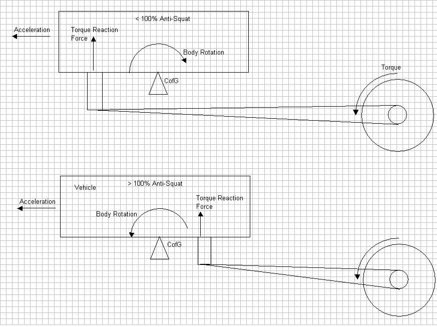
No... just the opposite. If you study the simplified drawing below, you'll see how anti-squat works. In the top picture, the torque from the turning wheels applies a lifting force on the end of the long swing arm. In this case, the reactionary force is applied ahead of the CofG of the car so it rotates the car backwards causing squat. In the lower drawing, the reactionary force is appplied behind the CofG and forces the weight to be transferred to the front of the car. 100% anti-squat happens when the reactionary force is applied through the GofG. Since anti-squat is measured as a percent, anything less than 100% means that the force is being applied ahead of the CofG, and anything over 100% means that the force is being applied behind the CofG.
Edit to add definition of 100% anti-squat.
[This message has been edited by Bloozberry (edited 03-10-2011).]
The drawings are just great, and a lot of man hours. I agree that there should be a repository for just for CAD files some where here in PFF.
One of the best books I have found on suspensions is "Race Car Vehicle Dynamics" by Milliken & Milliken ISBN 1-56091-526-9 , It's published by the Society of Automotive Engineers and you can get it on Amazon.
And it covers tri-link struts like ours.
------------------ yellow 88 GT, not stock white 88 notchie, 4 banger


 I thought it was supposed to be like that. The other issue was that since I drew it from the bottom up, I originally assumed that the spring's axis was aligned with that of the struts, only to find that the top hat would not line up with the top of the spring once I got to that point.
  It turns out the spring is actually offset towards the center of the car on the strut, presumably to give more room for the rear tire. Here’s the finished product in the uninstalled height configuration:
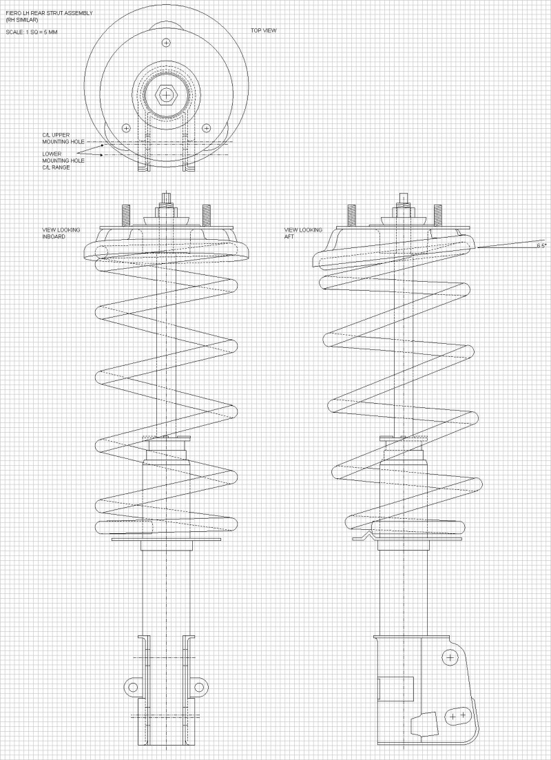
 , the internet, and a bag of Doritos to help refresh me in that department For now though, here's the top view:
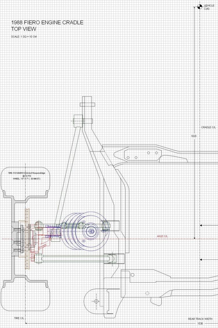


 oh yay).