Thanks for the bump litespd. I know it’s been a while since I posted an update, but I haven’t been sitting on my hands. I’ve been meticulously drawing out the stock ’88 cradle electronically for reference as I plan my own cradle design, plus Christmas shopping, filling out cards, and attending parties have gotten in the way, and most recently we had a 3 day power outage and property damage from 140 km/h (~90 MPH) windstorm. Wild weather!
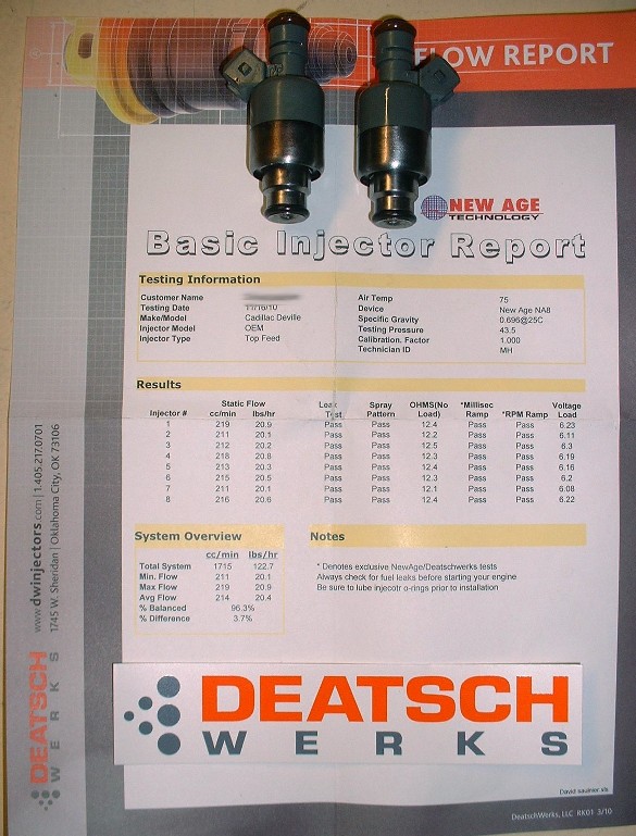
Anyways, I thought I’d take this chance to make a quick update on fuel injectors. Rather than replacing the OEM injectors with after market ones, I did some research and got some opinions here on PFF about cleaning them instead. There aren’t any shops in Canada that I could find that provide an uninstalled injector cleaning service, so I settled on sending them to an outfit in Oklahoma called Deatschwerks www.deatschwerks.com/catalog/injector_services.php Great company: fast turn around and a full report for $19 per injector. They disassemble, ultrasonically clean them, replace the internal filters, external o-rings, and test the coils, spray patterns, and compare flow rates. Not bad at all. Here’s my report card following cleaning. I can live with the 3.7% difference between the highest and lowest flowing injectors. Once I got them back, I masked the lower halves and painted them, of course, yellow!
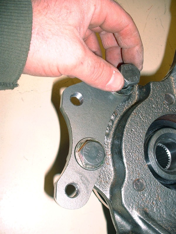
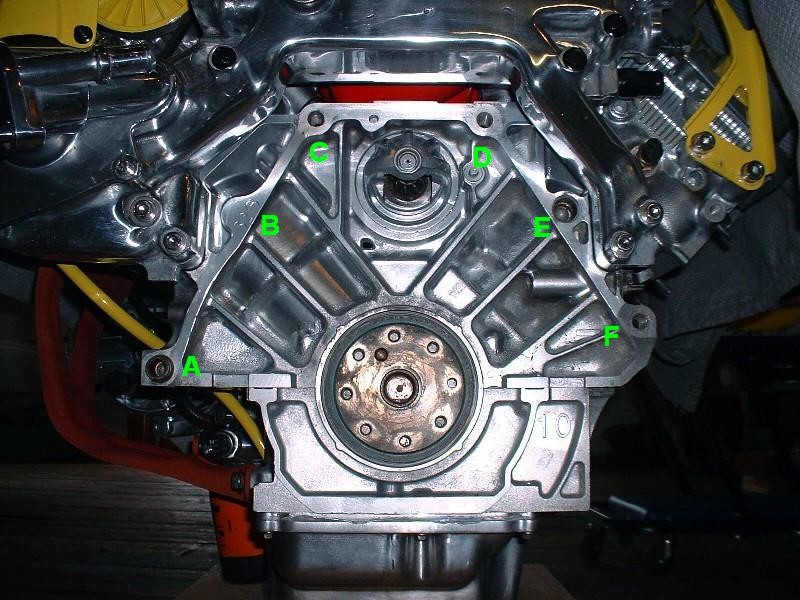
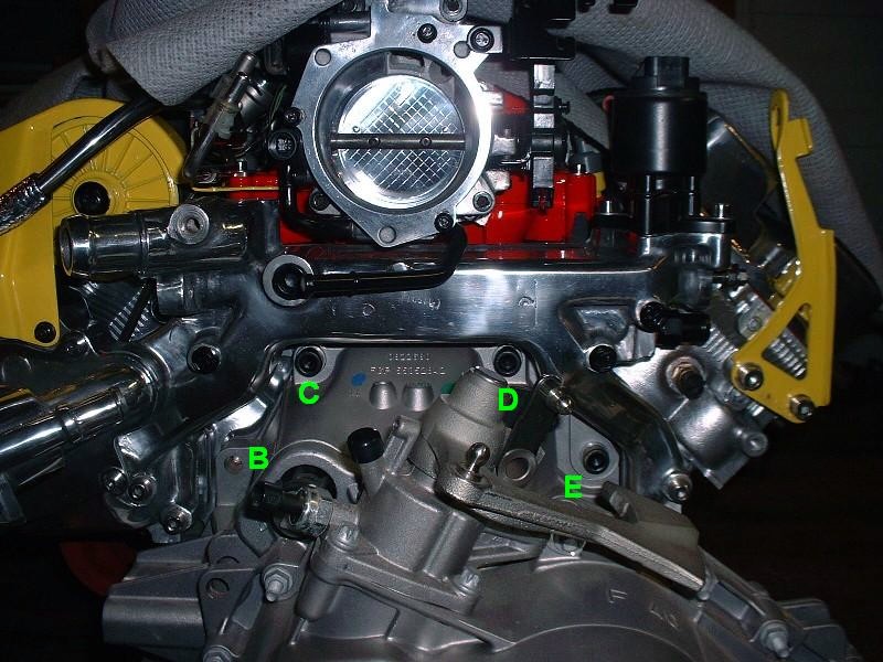
Now back to the transmission-to-engine mounting fun. Anybody who’s swapped a Northstar already knows the basic issues with mating one up with a standard GM Metric bellhousing pattern, but for those who aren’t familiar, this post is for you. For starters, here’s the rear view of the N*:
I’ve labeled the six locations for bellhousing bolts to illustrate which ones need massaging for the F40 transmission. The problematic holes are B, E, and F. Unfortunately there’s not much that can be done about mounting hole B. It’s not drilled or tapped on the N* for good reason. There simply isn’t enough depth of material between the bellhousing flange surface and the side wall of cylinder #8. It may be possible to safely drill and tap the location up to 3/8 of an inch deep, but then it wouldn’t serve much purpose, and it would more likely distort the cylinder wall or pull the threads out if any amount of torque were applied. Hole E is simply an unthreaded hole with an alignment dowel pressed into it, so it can’t be used as is to secure the transmission. The hole is waaaay larger than the M12 bolts used to mate the transmission to the engine. Finally, the problem with hole F is that the hole in the transmission bellhousing doesn’t line up with hole in the engine block.
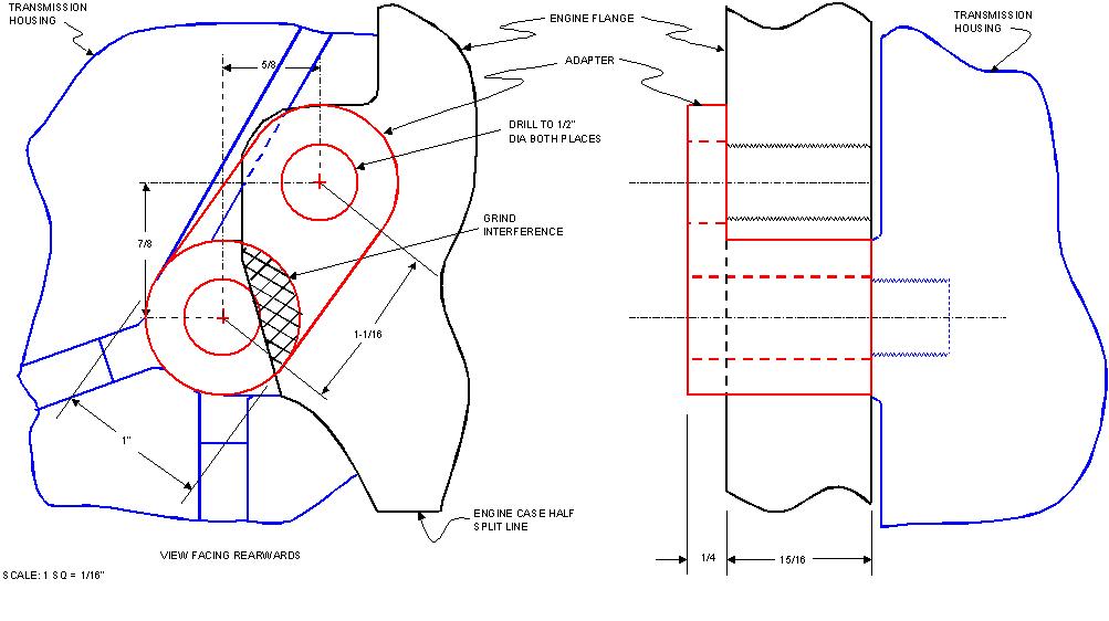
I started by addressing hole F. First, with the transmission mated to the engine, I drew out the dimensions of the two holes in relation to each other. This was an extra step I took so that anybody doing this in the future can design their own coupler with the key dimensions from the drawing. After some research, I decided to follow a similar (though not identical) design that PFF member “buds” used here, about 2/3 of the way down the first page www.fiero.nl/forum/Forum2/HTML/088691.html Note that regardless what design you use, there will be a need for some grinding on the engine flange since it covers a small arc of the actual bolt hole on the transmission.
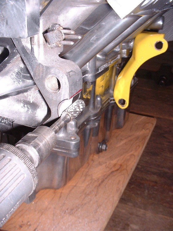
With my drawing in hand, I transferred the dimensions of the larger area I wanted to grind off the engine flange onto the flange itself. This is the view looking rearwards. (I traced the cut-out electronically onto the photo because there were too many reflections to see them properly in the photo.)
Then I used my handy grinding burr to remove the excess material. It ground down surprisingly easily, though I had to stop a few times to clean the bit to keep it from galling.
And here’s the finished product, although I had to make a few minor adjustments later on, which I’ll describe later.
Next I needed to make my adapter. I started out by cutting a 1-3/16” length of 1” diameter steel rod. It goes amazingly fast with the right tools!
Then I fabricated the flat portion out of ¼” steel plate, drilled the 1” diameter arc using a hole saw, and finished by beveling the edges for good welding penetration. Here are the two pieces clamped in the vise ready to be fused into a single piece.
A quick zip-zap with the MIG welder on the inside and outside of the mating surfaces.
… and here’s the finished product once the welds were ground down smooth, and after a quick trip to the lathe to drill the 1/2" diameter hole through the center of the rod. The inside filet is the reason I needed to make a few adjustments to the engine flange notch. To make the adapter sit properly, I needed to grind a beveled edge on the flange.
The moment of truth actually took a few test fittings since I found I hadn’t ground away enough aluminum from the flange even after beveling it. No biggie. To install the adapter, I used an M12 X 1.75 X 70 (12.9) in the lower hole, and an M12 X 1.75 X 35 (12.9) in the upper hole.
Edited to change bolt lengths used.
[This message has been edited by Bloozberry (edited 02-21-2011).]
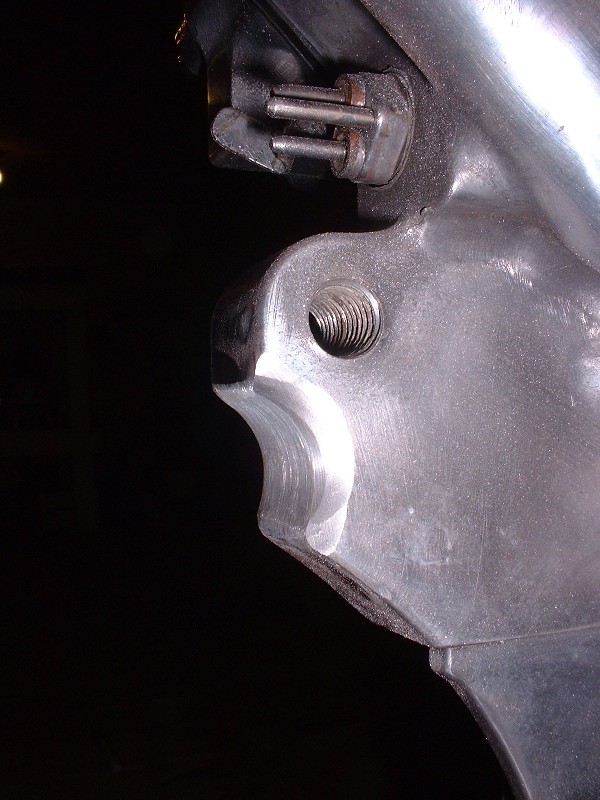
Next up was to figure something out for hole E. I did a bunch more research here on PFF but couldn't find anyone who had used this hole for a bellhousing bolt. Again, the problem with this hole is that there’s an alignment dowel pressed into it, but the inside diameter is not threaded at all. To make matters worse, the alignment dowel is pressed in very tightly making its removal very difficult. At first I tried the same method I used to remove the cylinder head dowels by shoving a steel rod down into the ID of the dowel to prevent the sides from collapsing as I tried clamping and turning the dowel with Visegrips. It wouldn’t budge and ended up galling up the sides of the dowel. I didn’t think of taking pictures at the time since I didn’t think removing a dowel would be worthy, but I took some afterwards given what I had to do to get it out.
After some measurements I found that the ID of the dowel was just about right to cut some 5/8” threads into it, and I happened to have the 5/8” X 11 tap handy from when I used Norm’s head bolt insert kit. So at first I thought I would just tap the OEM dowel ID, and up-size the bellhousing bolt to 5/8”. But then I realized that wouldn’t provide any clamping force because the dowel isn’t mechanically locked to the engine block except through an interference fit. But it did give me an idea on how to go about removing the dowel, so I tapped the ID anyways. Here it is mocked up with the tap after I actually got it out.
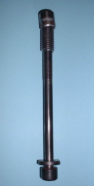
Then, using a spare insert from Norm’s headbolt insert kit (he sends you 21, but you only need 20), I threaded it into the dowel, and then threaded one of the used head bolts into the insert.
Finally, using a slide hammer under the head of the bolt, I was able to pull that sucker out of the block. What a PITA!
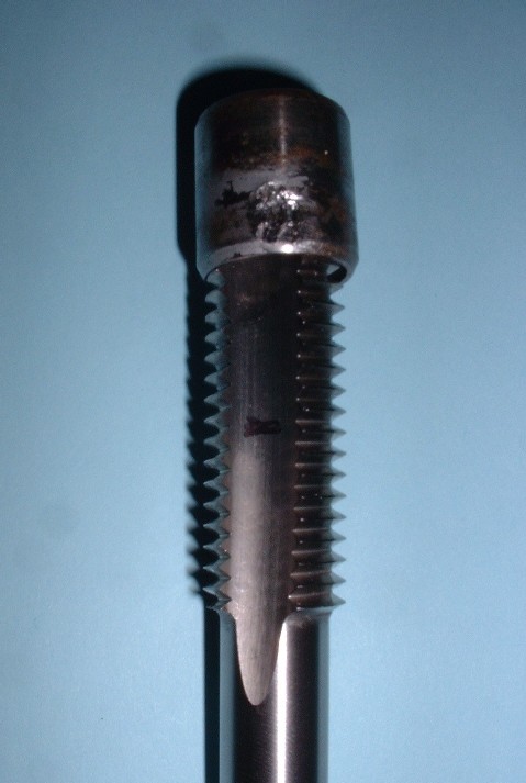
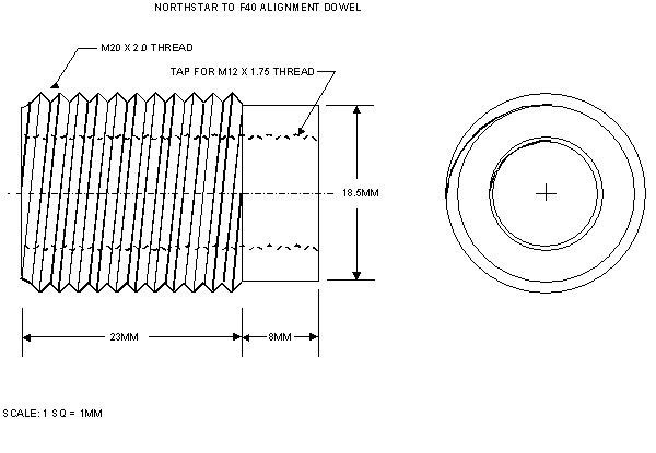
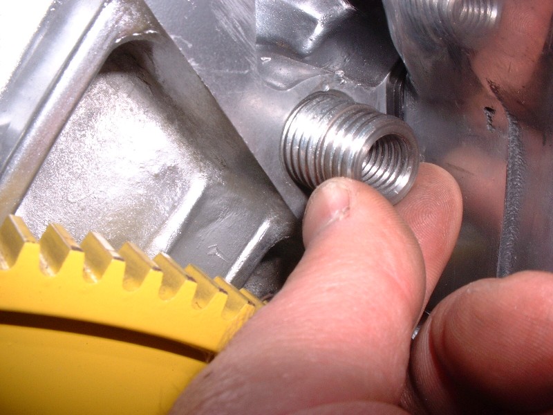
Now to make hole E useful, the idea was to fabricate a new alignment dowel that was threaded both on the outside diameter to lock it to the block, and on the inside diameter to allow a standard M12 x 1.75 bellhousing bolt to be used to bolt the tranny to the block. I drew out a schematic of what the new threaded alignment dowel should look like with the appropriate measurements so you don’t have to go through it all yourself:
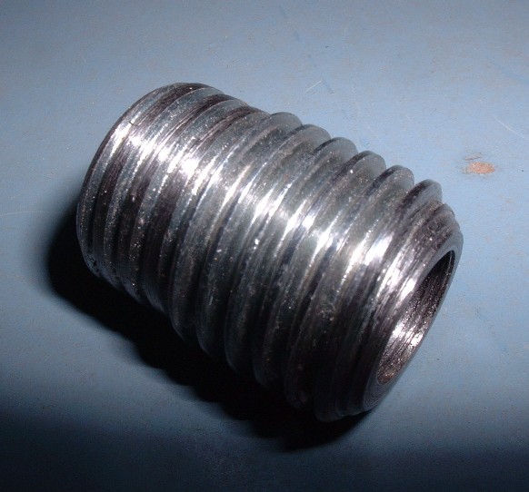
To make it, I bought an M20 X 2.0 X 60 bolt ($3) and had a friend with a machine shop remove the head, then machine the threads off one end along an 8 mm length to a new OD of 18.5 mm, which is equal to the OD of the OEM dowel. You’ll notice from the picture that it didn’t end up removing the entire depth of the threads, but that doesn’t matter. This will be the end that will stick out of the block. Then he drilled and tapped the core of the new dowel for the M12 X 1.75 bellhousing bolts, and finally cut it to the correct overall length.
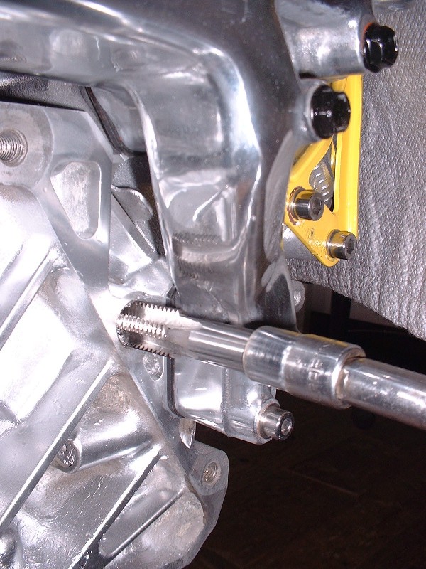
Next step was to tap the engine block where the old dowel was. The hole, as mentioned before, is 18.5mm in diameter, so that’s why I went with the 20mm bolt for the new dowel. I bought an M20 X 2.0 end tap ($36) and threaded the engine hole without any problems.
Just be careful if you do this not to over torque the tap as you reach the bottom since you risk stressing the cylinder wall.
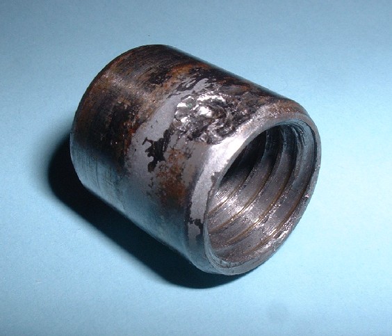
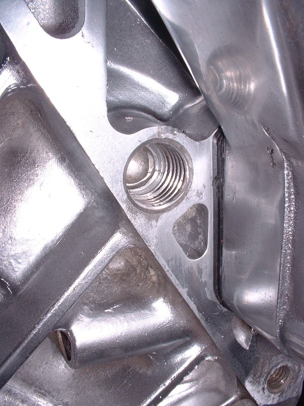
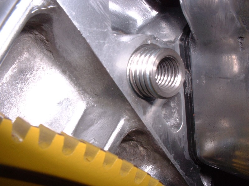
The rest was a walk in the park. I just screwed the new threaded alignment dowel into the block (I’ll use thread locker for the final installation later on).
Make sure that the OD threads of the dowel are completely recessed into the block and that the only part protruding is the part that the threads were shaved off:
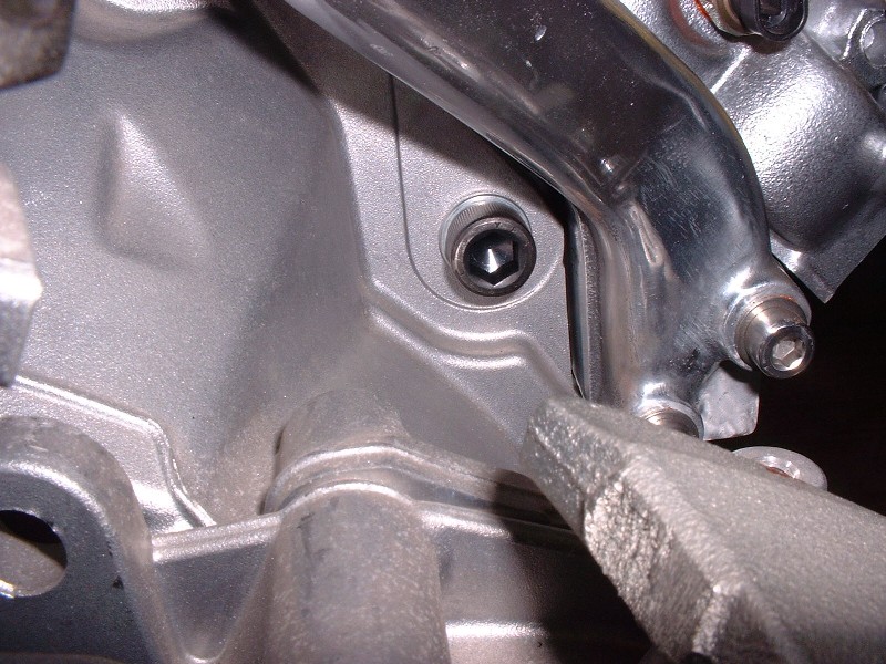
And install the transmission.
I used the following length M12 X 1.75 bolts in the locations identified in my last post: A = 50mm, B = nothing, C & D = 70mm, E = 30mm, F (top) = 35mm, F (bottom) = 70mm.
Blooze, this is probably one of very few detailed engine swaps here I've ever seen on PFF. I love the fact that you describe / mention / show what is going into the project. Plus the cleanness and show quality that is going into it. I'm not a fan of yellow paint, but that's your taste and preference. The top intake that is painted "fire red" is an awesome color; very hot.
Not just putting a engine and tranny together is the issue here, its all in the detail and recommended torque values indicated. Not many folks respect doing that when doing assembly. You know what I mean, not just torquing the heads down and the rest isn't important.
You do quality job and in the end it pays off, big time !! Plus you got on hell of a nice swap ! :P
Have a good X-mas...
------------------ fierogt28
88 GT, Loaded, 5-speed. 88 GT, 5-speed. All original.
Thanks for the compliments Amida, fierogt28, and DeLorean00. I sometimes wonder whether I'm overdoing it with too much info and too many pictures of stuff that may be obvious.
quote
Originally posted by DeLorean00:
What is your background if you don't mind sharing?
I'm an ex-military aircraft engineer. I retired six years ago as the senior aircraft maintenance officer at the headquarters level on Canadair Challengers, the Snowbirds aerobatic team aircraft (Tutors), and the now retired T-33's, and F-5's.
Ditto! I'll never be able to come close to doing your caliber of work nor can I afford it, but I always await your latest post with great anticipation. I appreciate the work that you do and the effort you put forth to share it. Thganks again
You guys are what makes keeping this thread fun for me. For 17Car, I haven't started sorting out the electrical issues yet, which I know there will be plenty. I'll probably start that part of the project after the cradle.
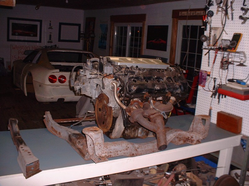
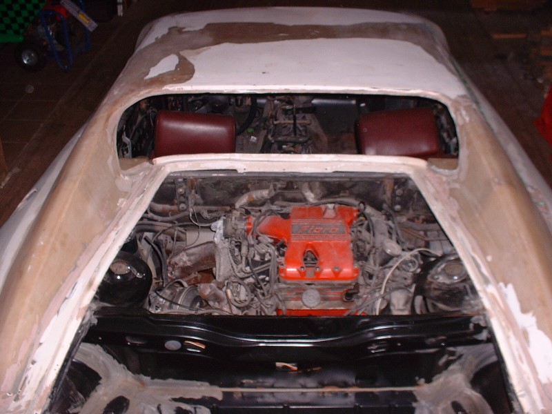
The Northstar and F40 at this point are only temporarily mated since the clutch and flywheel aren’t yet installed. I am still contemplating the pros and cons of various flywheel configurations and clutch suppliers, but that didn’t prevent me from progressing in other areas. For starters, the old 2.8L engine and auto tranny had to come out of the chassis. Here it is, albeit a little out of focus, looking a little lost in the engine bay of a “Ferrari”.
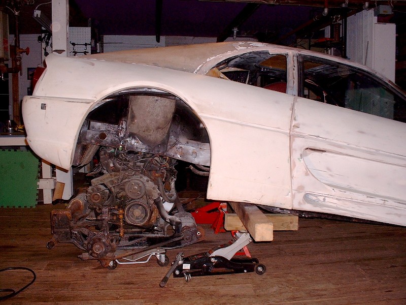
The way I remove the engine and cradle from a Fiero is by jacking it from both sides of a 6” X 6” or 4” X 4” post slid under the area just ahead of the front cradle mounting ears. If you choose to do it this way, you must be sure that either the jacks are free to roll forward or the front wheels of the car are free to roll backwards, since the jack pads move fore and aft relative to the body of the jacks as you raise them. Catastrophe awaits those who don’t heed this advice.
Once the car is raised high enough for the plenum to clear the lower passenger side frame rail, I roll the engine out from the wheel well. You don't have to raise the car nearly as high if you pull it out of the wheel well compared to pulling it out from the back of the car because the trunk floor sits considerably lower than the side frame rail.
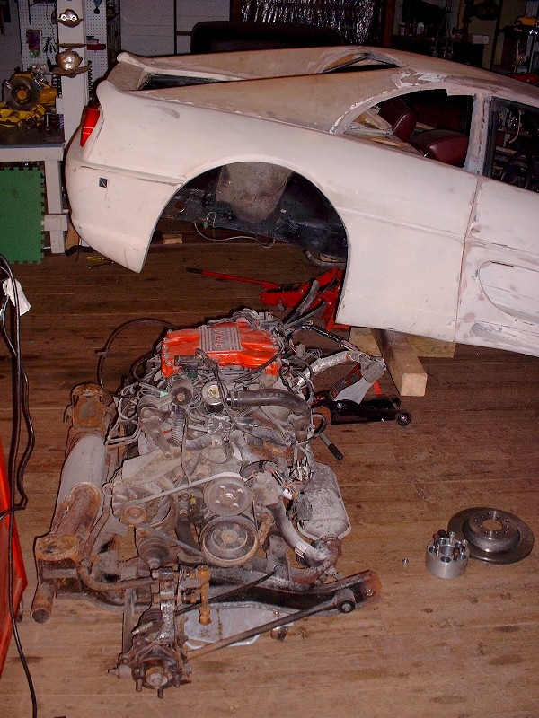
This car was an automatic, making my conversion a little more involved that it otherwise could’ve been had it started out life as a manual tranny car. It’s a low mileage one though with only 97,400 kms (60,900 miles) since the car has been on jacks since 1999. It still has the (piece of junk) pellet style OEM catalytic converter! I had hoped to use the ’88 cradle for my Northstar as many have done, so I proceeded to separate the 2.8/auto combination from it. This is always a fun time because a little effort produces huge visual results.
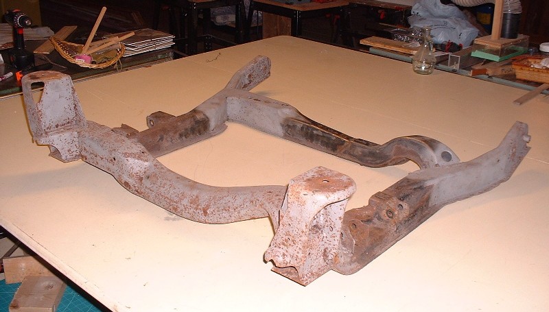
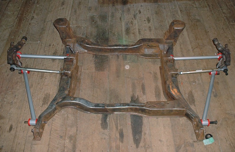
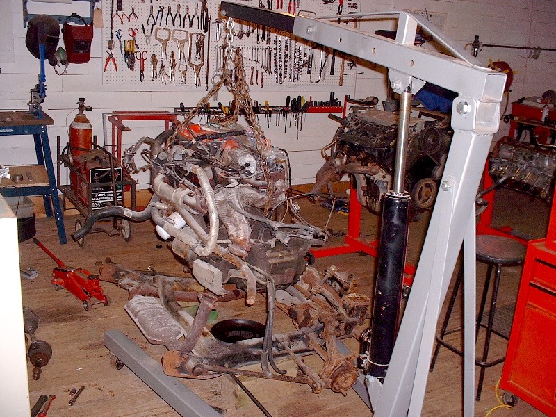
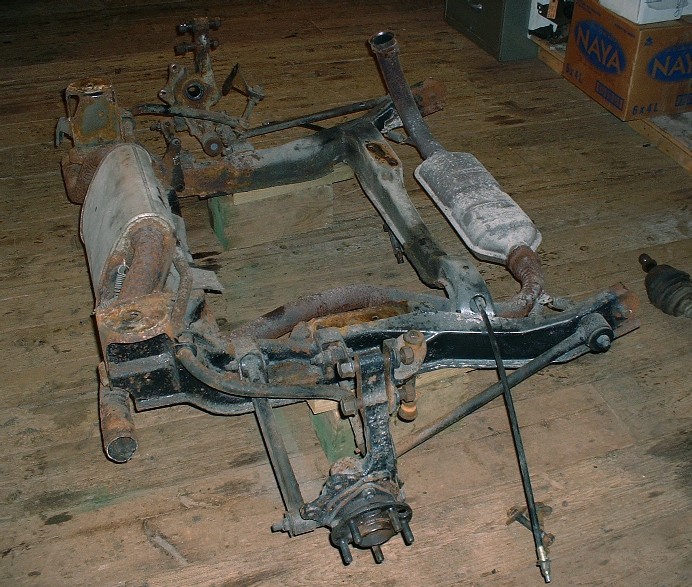
Here's the cradle with the engine removed:
I’ll probably rebuild the '88 engine and keep it as a spare, ready to drop in my ’86 GT if it ever needs it. I also have an ’85 parts engine that could be rebuilt but I don’t think I could ever justify the expense. It’s going to be hard enough to justify rebuilding the ’88! The transmission is up for grabs though since I can’t ever see myself using it.
And here’s the shoebox that the Northstar will some day occupy. It should fit with a little more room to spare than most of the Fiero N* conversions since the frame had already been stretched 3” when I bought it (thanks Rick!).
[This message has been edited by Bloozberry (edited 01-08-2011).]
I like your work You have given me some ideas. IF, I could give a bit of advice I would recommend starting the engine on the cradle outside of the car before the installation. That way It is SSOOOO much easier to trouble shoot any problems. Just don't run the water pump dry They are enough work just to remove and install once, don't want to have to do it more than needed. It is amazing how easy it is to have one bad wire after doing 100+ splices. I was even able to check for exhaust leaks and water leaks. I have done this with every swap I have ever done.
[This message has been edited by Rickady88GT (edited 12-24-2010).]
I see you have a 355 kit very similar to my kit that I started out with. Attached rocker, dip in the rear bumper and the rear bumper slopes up toward the rear fender well.
I can email you how to line all that up if you like. I did the same thing on my 355 build as well as separated the rockers and redid the rear bumper to level it out and create more definition in the lower rear bumper area. Not to much work and it really makes a difference in the final look of the car.
I will be done my 308 conversion this January and then it is back to the 355 to finish it off as well.
I would recommend starting the engine on the cradle outside of the car before the installation. It is amazing how easy it is to have one bad wire after doing 100+ splices. I have done this with every swap I have ever done.
Hi Rick, thanks for the advice. I hear what you're saying, and I may be tempted to try that once it's mounted to the new cradle, although I find the propsect rather intimidating.
quote
Originally posted by 355Fiero:
I can email you how to line all that up if you like. I did the same thing on my 355 build as well as separated the rockers and redid the rear bumper to level it out and create more definition in the lower rear bumper area.
Great minds think alike there 355Fiero. These are all things I plan on doing to my car as well. I can't stand the rockers being part of the doors, nor what the car looks like when you open the doors with them that way. I don't want to spoil all the surprises on what I'm going to do to my car here in the thread yet, but suffice it to say that the poor IFG body is going to go through a make-over. I'd love to see how you did yours for inspiration, I'll PM you my email address. Merry Christmas!
[This message has been edited by Bloozberry (edited 12-27-2010).]
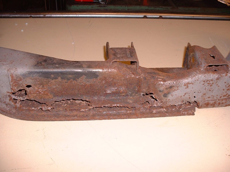
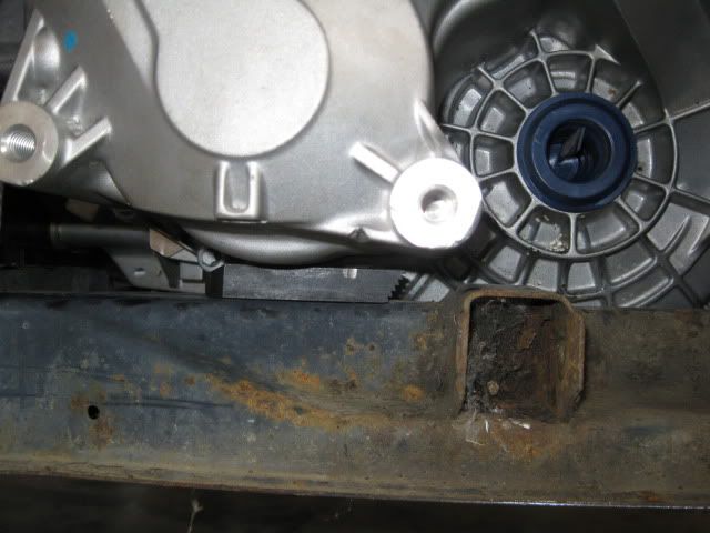
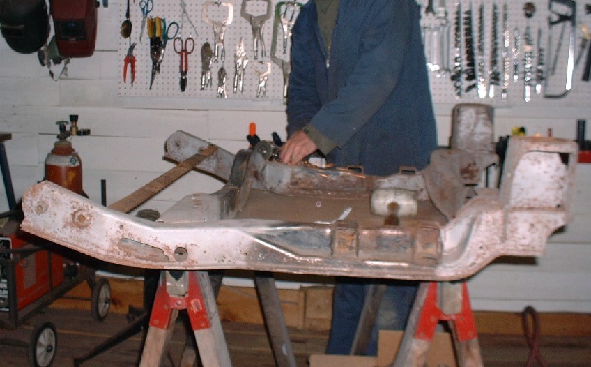
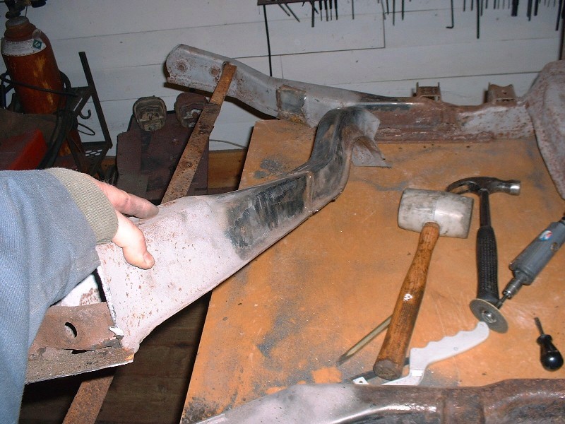
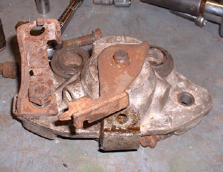
With the old engine off the cradle, assessing the cradle’s condition was the next step. I wasn’t prepared for what I’d find, that’s for sure. The cradle was covered in grime and loose scaly rust so the first step was to wash it in varsol and take it outside to sandblast it. From this picture, you can see that I didn’t bother sandblasting the whole thing once I realized the condition of the cradle.
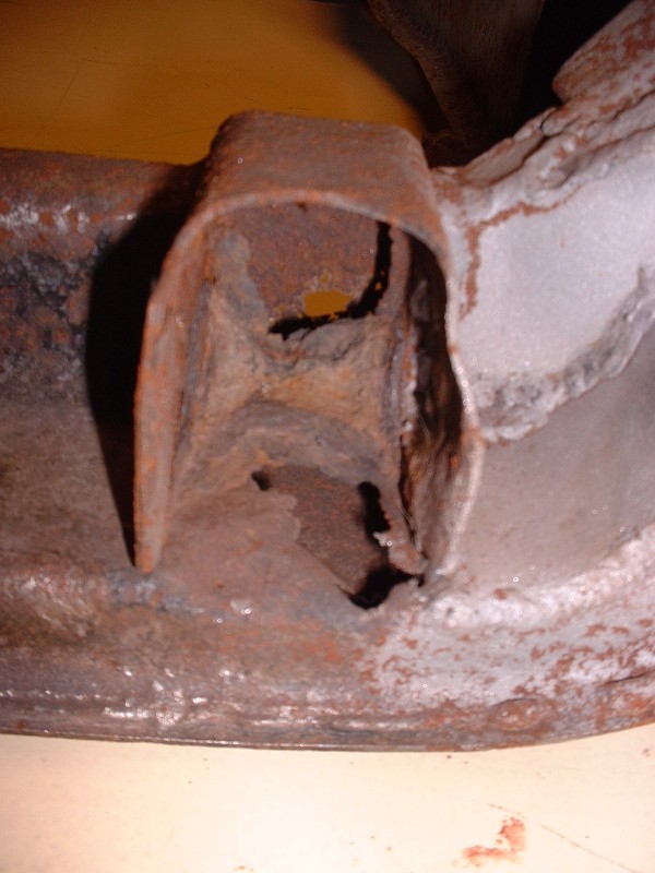
I could see that there was some serious hidden rust in key areas so the first thing I did was cut off the front engine mount shelf to get a better look. It wasn’t at all inspiring. This is the right hand cradle side rail under the mount.
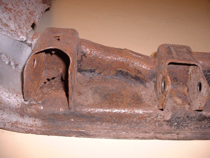
Here are the two mounting points for lateral links on the right hand side. Not much structure left holding the rear mount in place. If you look carefully to the left of the photo, you can see where some one tried to weld up some of the holes with sheet metal.
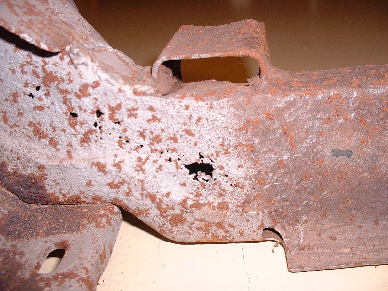
Here’s the inside view of the left hand cradle side rail. Most of this rust damage wasn’t visible before I started sandblasting. It’s like Swiss cheese! The thing is, that with this level of perforation rust, you just know that the rest of the structure is only a fraction of the original wall thickness, even though you can't tell from the outside.
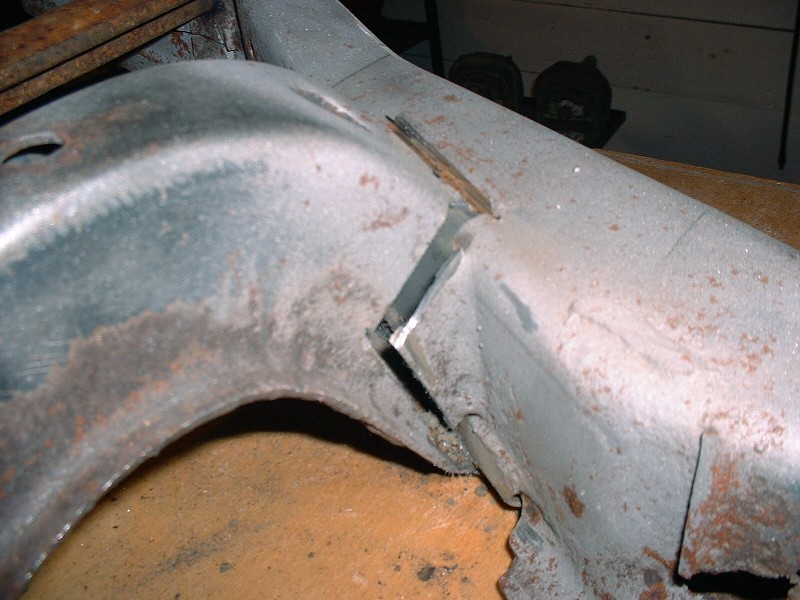
And this is the rear-most lateral link mount on the LH side rail… it’s barely hanging on! Again, somebody tried to salvage the cradle with a few patch panels but obviously wasn’t aware of the extent of the damage I uncovered by sandblasting.
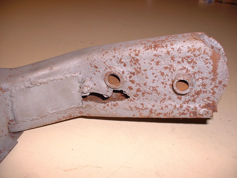
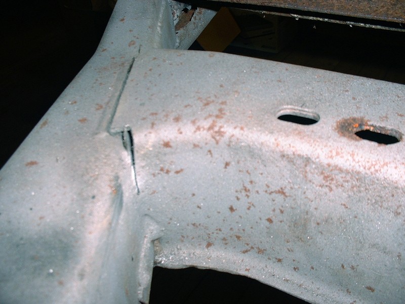
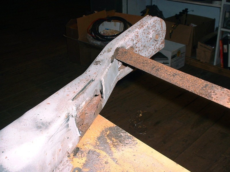
The front cradle mounts weren’t spared from the rust bug either. This is the left hand one that’s eaten through in a critical area as well… the left-most hole is the trailing link mounting point that takes all of the accelerative and decelerative forces of the rear suspension.
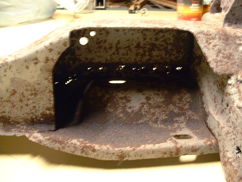
And here’s the rear transmission mounting pocket. I’ve played with the contrast of the picture to highlight the problem. One thing this project has taught me is that the corollary to "Ignorance is bliss", is "Knowledge is bliss for Visa".
Wow that's some bad cancer as it wasn't readily apparent. Now I have to go out and recheck my cradle even though I have already. What state was the car used?
Wow, sorry to see how bad that is... I am curious to see if you look for a replacement that you will have to modify or just make another using this one as a template?
Blooze, that cradle is painful to look at. I just hate it when a project takes a turn like that. Seeing what you've done so far, I think I can guess what you might do about the cradle, but I'll let you suprise us.
Joe
[This message has been edited by motoracer838 (edited 01-01-2011).]
Erik, the car was from Ottawa Ontario, lots of salt used on the roads there. Rick, luckily the rest of the car seems really good. There’s a few little spots that’ll need a little attention, but nothing more than some stripping, priming and painting.
Charlie, Motoracer is on the right track. I won’t be needing another ’88 cradle… at least I hope I won’t!
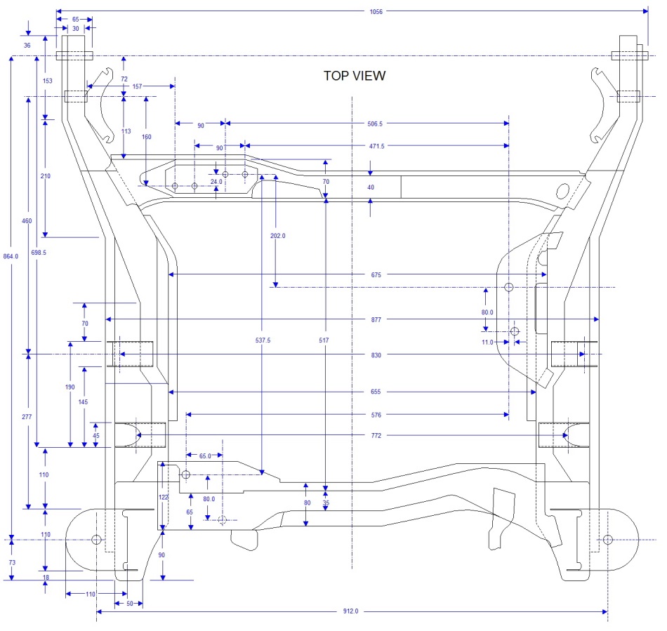
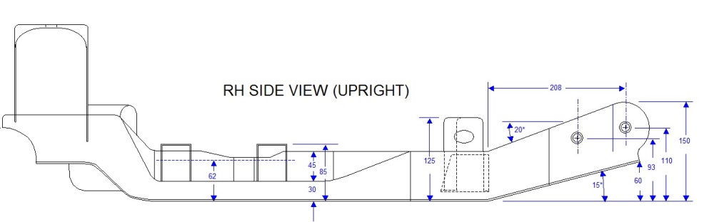
So I’ve been quite busy over the last couple weeks chipping away at some drawings of the ’88 cradle. I figured that before I cut out the front cross member, I should have some decent measurements of the whole thing. I was aware of the cradle drawing in the service manual, but if you’ve ever had a close look at it, there’s really not a lot of information contained on it, only the relative positions of the various mounting holes to one another, but not to any other part of the frame. My initial scope was to plot only enough information to assist me in designing a new cradle, but of course that turned into measurements of just about everything.
So for what it’s worth, here are the fruits of my labor, to be copied at will, I only ask that if you use them, to give credit where it’s due. I can email anyone with larger and greater resolution versions if so desired. Understand that in order to post them, I had to chop up the much larger diagram into it’s different views, so in many cases, if you’re looking for a measurement that isn’t in one view, it will be in another.
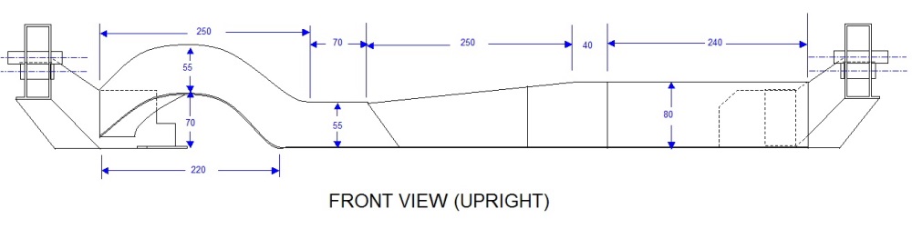
Here’s the front view of the cradle:
The top view:
The RH side view (which is nearly identical to the LH side view, so I didn’t bother drawing it out):
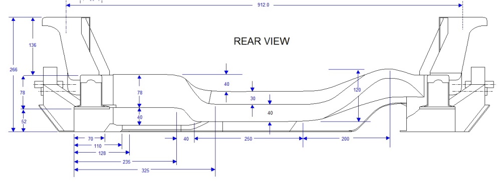
And the rear view:
With this work done, I was ready to start mocking up my spare Northstar to the old cradle to get some engine-to-tranny-to-cradle reference measurements.
[This message has been edited by Bloozberry (edited 04-01-2014).]
Those are some pretty detailed drawings... I just imported the PDF of the service manual dwg into AutoCAD, scaled it to some known dimensions, and then outlined it... but then found out that the service manual drawing isn't square.
I would love a copy to add to my drawings. Please email it to fieroguru@lycos.com
Once you start building a new cradle, I recommend you lower the bottom of the cradle about 1" and push the side rails further out (not as much material inboard of the lateral links) to gain more clearance for the F40. Doing so will allow you to mount the engine/tranny as low as possible without the cradle rail getting in the way or the oil pan sticking below the bottom of the cradle.
I guess since you are doing a 355 with a wider stance, you could just build the extra width into the cradle as well.
[This message has been edited by fieroguru (edited 01-02-2011).]
Fieroguru, these are all excellent ideas. I'm still in the brainstorming phase of what to incorporate into my new cradle. Moving the frame rails outboard was one of the top priorities to make more room for the powertrain. And although I've already bought Held's 6" track width control arms, I may still choose to move the control arm mounting points outboard another inch too. That will open up a larger variety of wheel options given the rather limited offsets available for some of the nicer wheels I've been eyeing. There's no point in using spacers if I can design them out of the equation!
I'm not sure I understand your rationale for lowering the bottom of the cradle though.
Another major consideration is raising the control arm mounting points since I will accomplish getting the wheels at the right height in the wells by a combination of adjustable coil-overs, and raising the strut tower mounts. With no other mods, this of course would angle my control arms upwards and alter the dynamic camber change. So raising the mounts should restore the stock geometry while raising the wheels into the wells. But then I want to research anti-squat, and a host of other issues too, so more grey-matter needs to be exercised.
BTW, I sent you and BMTFiero the source file for the cradle drawings via your email accounts.
Thanks for the drawings. When I get an afternoon or two, I might put them into AutoCad.
As for lowering the bottom of the cradle, this allows you to lower the drivetrain to lower the CG and give you more clearance to the decklid hinge boxes, but doing so puts the axles at an upward angle as they go to the wheels. In the end it is a matter of personal preference.
Raising the front mount for the lateral link will reduce squating and is farily easy to do. Raising the lateral links at the cradle with the F40 is going to be a challange... not much room to move them, unless you raise the entire drivetrain. Depending on where you place the axle centerline vs. the wheels a large bolt boss will be very close to the front lateral link mount.
I am looking forward to seeing what you come up with for a cradle!
FieroWannaBe: I took measurements from several places on the cradle to determine the original thickness of the metal and I got anywhere between 0.090” to 0.100”. The rustiness probably had an impact on the variability in wall thickness, but this should give you a range to work from.
One last thing I did before cutting off the front cradle crossmember was to mock up the new Held’s rear tubular control links just to make sure they would align as promised. Here’s a sneak peak at what’s coming in the next post:
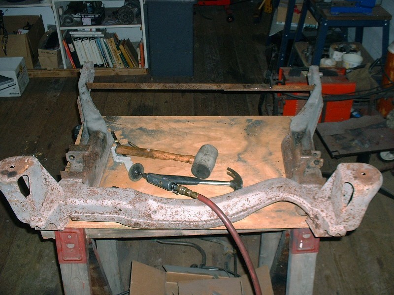
As most people reading this thread would know, the placement of the Northstar engine with the F40 transmission interferes with the OEM front crossmember, so the crossmember must be moved forward. I welded in a piece of angle iron between the two cradle side rails before doing any cutting to keep the rails properly positioned in relation to each other once the OEM front crossmember is removed.
I used a cut-off wheel in my die grinder to cut through most of the welds holding the OEM crossmember to the side rails, although it was tricky to get the cutting wheel up the rear wall of the crossmember due to the angles. I found that the crossmember was under some stress because it sprang forward about a quarter inch once the final cut was made on the RH side.
On the LH side, there was just no way to get the cutting wheel in the back corner so I resorted to using an open-ended hacksaw to get the rest of it. You have to be patient though because you can only get a couple inches on each stroke before the blade hits the inside opposite wall. This is where it would be nice to have an oxy-acetylene torch… and concrete instead of wooden floors!
With the final cut done, the crossmember just lifted out.
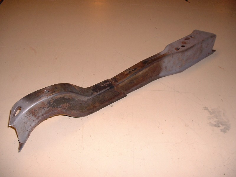
Here’s the offending piece. If only Pontiac would have had the forethought to install a Northstar-friendly cradle, things would have been a little easier! Surely the Northstar was on the drawing table at the time?
And looky-looky what have we here? More rust hiding in a critical area. Such a shame to have more iron ore than steel on an ’88 cradle.
Here’s the overall view of the cradle without the OEM front crossmember. Again, the reason for me doing this even though I don't plan to use the cradle at all, is to be able to properly locate the engine and transmission assembly in relation the OEM cradle mounts, which dictate the location of the axles.
I’m using my spare engine for the mock up purposes so as not to accidentally damage my beauty queen. After setting the ugly sister on the bench, I had been hoping to be able to slip the cradle over top of it to get it in place… no such luck! So I needed the engine hoist again to make it right.
So then, the next obvious step in the process would be to bolt the transmission to the back of the engine and start designing powertrain mounts. That would be great if the new cradle were going to be similar to the old one, but since I want to make a number of design changes (not all of which are clear in my own head yet), I need to spend more time at the drawing board. My goal is to have the old cradle, the F40, and the Northstar drawn out electronically so I can visualize the interrelationship between things like powertrain placement and planned suspension geometry changes. The electronic format will allow me to cut and paste at will, while minimizing time fabricating parts that don’t fit. Obviously it is going to be a time consuming process to draw multiple scale views of the transmission and engine, so I’ve saved some photos of the suspension upgrade process to keep the thread alive while I'm drawing.
For starters, here’s what the previous owner had in mind to get the wheels out three more inches per side to fill the wheel wells. Yep, three inch spacers:
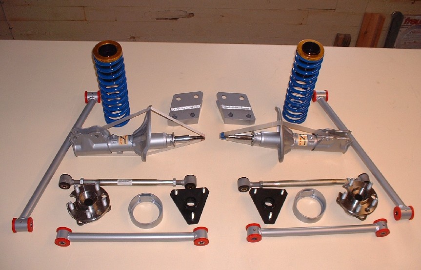
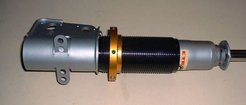
I don’t have anything against wheel spacers in the rear of a car where steering is not an issue, but moving a front wheel out by three inches makes the center of the tire contact patch walk around a 3” radius rather than pivoting on its center, among many other negative influences. Since I had the money to make it happen, I decided to spring for a better way to space out all the wheels. (BTW, anyone interested in a brand new set of four 3” polished aluminum spacers 5 X 100 on 5 X 100 for $50 each plus shipping, just PM me). This is the HT Motorsports (www.westshorefabricators.com/Fiero/index.htm) tubular rear suspension package, including do-it-yourself adjustable coil-overs, plus new KYB GR2 struts I bought locally. (The eagle-eyed among you will notice that I accidentally included a pair of front suspension parts in this photo too).
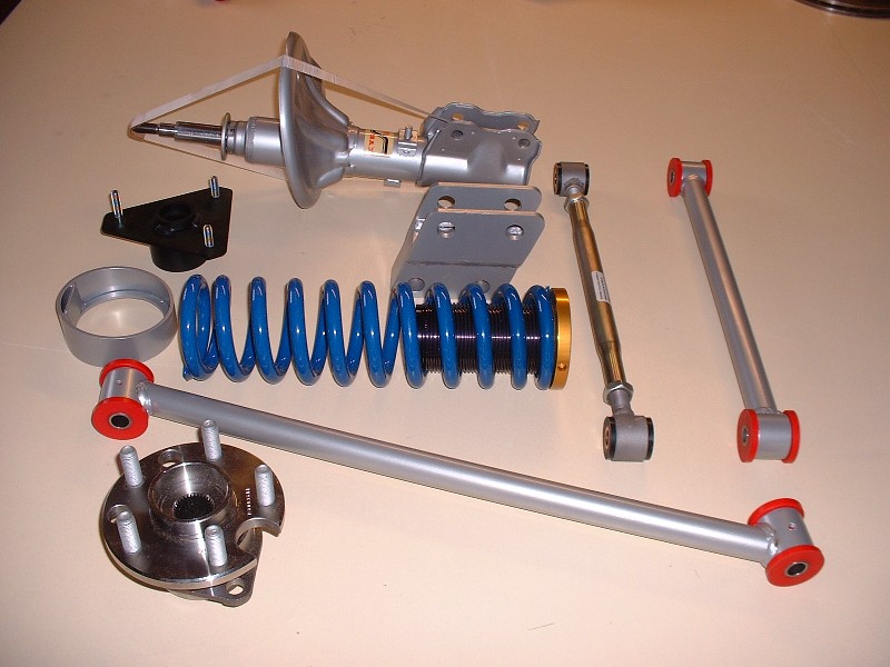
Here’s another view of the parts for one side. All kinds of nice new shiny parts! Eric at HT Motorsports will powder-coat your suspension pieces any color you like, although silver is not a common color, so at the time he didn’t keep any in stock. It took an extra week or so delivery-wise before he could fabricate the parts and have them done in my choice of color.
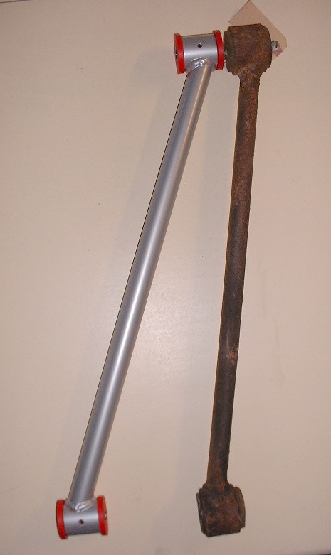
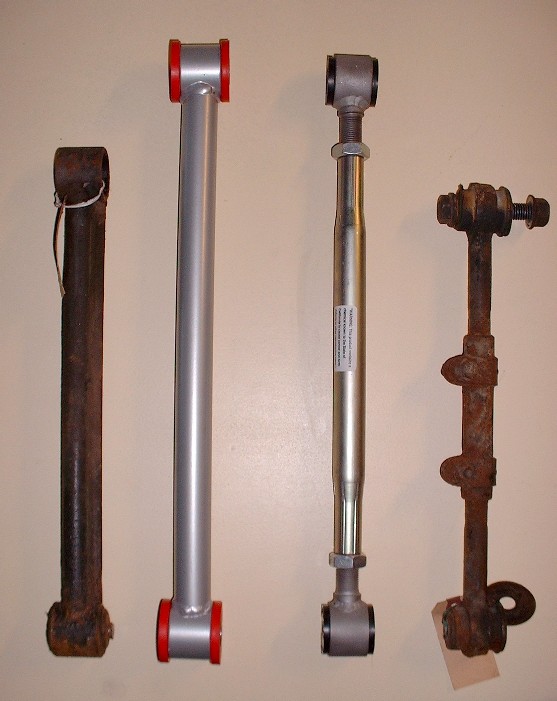
Here’s a few close-up shots of the parts. This is the trailing link compared to the OEM one. The link itself is only marginally longer, but the big difference is in the angle it must meet up with the knuckle:
Here are the lateral links for comparison. The nice part is that all the links came with polyurethane bushings, although recently I discovered that the inside diameter of the sleeves for the bushings had unacceptable variances (Thanks Rodney.)
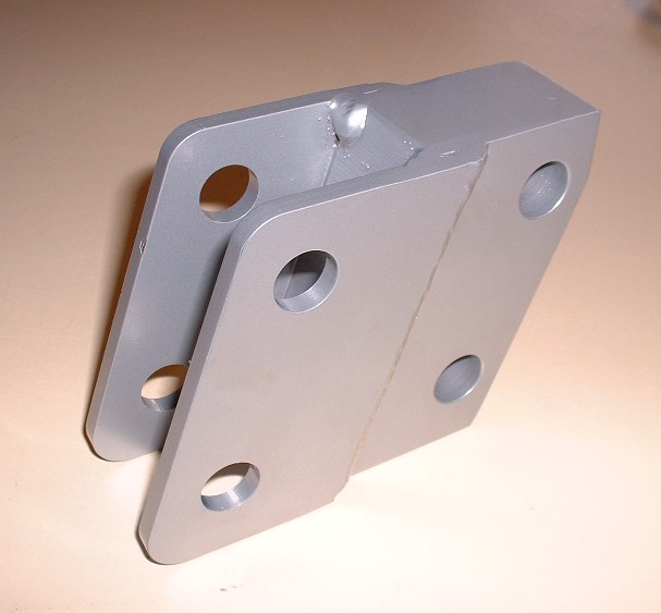
This piece is an interesting but unfortunate necessity. It’s a strut to knuckle spacer. By moving the knuckle outboard (which incorporates the lower strut mount) the angle of the strut would change significantly if nothing else were done since the strut upper mount is fixed. Two ways to remedy this is to either move the top strut mount outboard as well, or to use a lower strut mount adapter like this. The jury is still out regarding what I will do to solve this problem. I bought the parts, but now I am leaning more heavily towards changing the upper strut mounts for several reasons which I’ll get into later. One of the obvious ones though is to shed the needless unsprung weight of these adapters.
Thanks 1fatcat. I just noticed that the number of views is now over 15,000! I would never have guessed there would be this much interest.
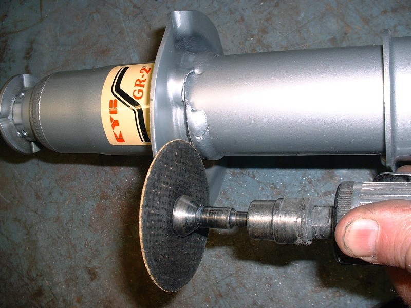
Anyways, with all the parts on hand to modify my new KYB’s into coilovers, I decided to convert them next. There are lots of threads on how to do this but I figured I’d document the process to buy more time drawing the tranny. Converting them was really quite easy. All it took was a die grinder with a cutoff wheel and a steady hand. The idea was to cut the old spring perch off the strut where it’s been welded on. I cut just above the weld and slowly went deeper until I could just see the underlying strut tube. It almost hurt to take the wheel to these brand new parts.
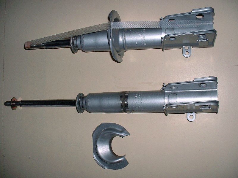
Once the spring perch was off, it was a simple matter of grinding the weld down flush with the tube body using the bench grinder. I found I had a lot more control doing it this way than with an angle grinder, which others have said they used. I also found that I had to get every last bit of weld off to be able to slide the threaded adjuster tube over top. Here’s the before and after picture of the two struts.
The next step is to slide the threaded adjuster tube over the strut body. It’s a tight fit. It comes to rest on the knuckle flange and would be OK just to leave it like that, but I used a bunch of silicone sealant between the two parts to keep moisture out and to keep the threaded tube from rattling against the strut body. It probably wouldn’t ever make noise given that the spring will always keep tension on it, but there was no harm doing this extra step.
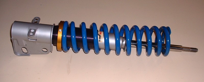
Once that was done, I slipped the springs onto the strut and seated them on the adjustable collar. I was somewhat wet behind the ears with respect to spring rates when it came time to order rear components. On the one hand, I didn’t want a rattle-my-amalgam-fillings-out-of-of-my-teeth ride like my 308 kit, but on the other, I’m planning for only about 4” of ground clearance so it can’t be soft either. Throw on top of that the added weight of the Northstar/F40 and the added leverage of the longer suspension links, I just didn’t feel like I had the ability to choose correctly. So I fed all of my particulars to HT Motorsports and had them recommend what they thought would be the best set up. This was at the time HT was being transferred to the new owner Erik, so I got the “benefit” of the old owner’s experience (Lee, I believe).
Lee suggested 350 in/lb springs in the rear and 325 in/lb in the front, despite my inner voice telling these are going to be way too stiff. He said that if I wasn’t happy with them, and as long as they were still in good condition, he would exchange them. I wonder how many years this offer is valid for… They’re 2.5” diameter X 12” (I believe) in the rear.
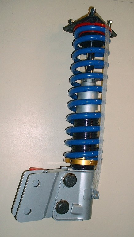
Enough about springs… to keep them in place at the top end, it’s a simple matter of sticking on a washer, a shaft bushing, followed up by a polyurethane spring seat, the hat, another shaft bushing, another washer, and the locknut. Tah-da! One adjustable coil-over:
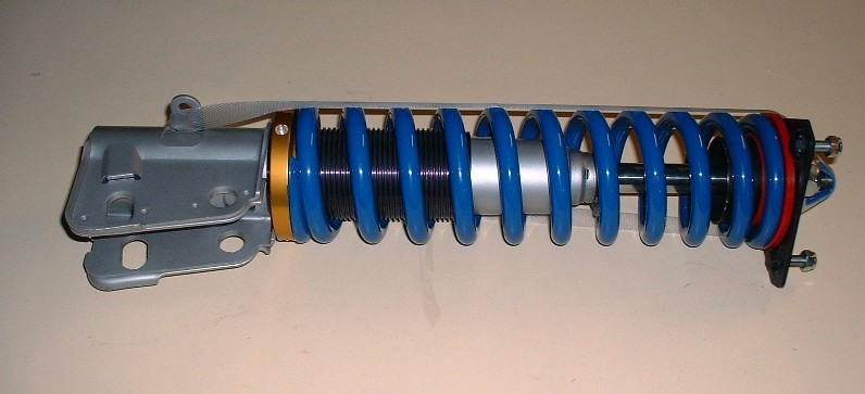
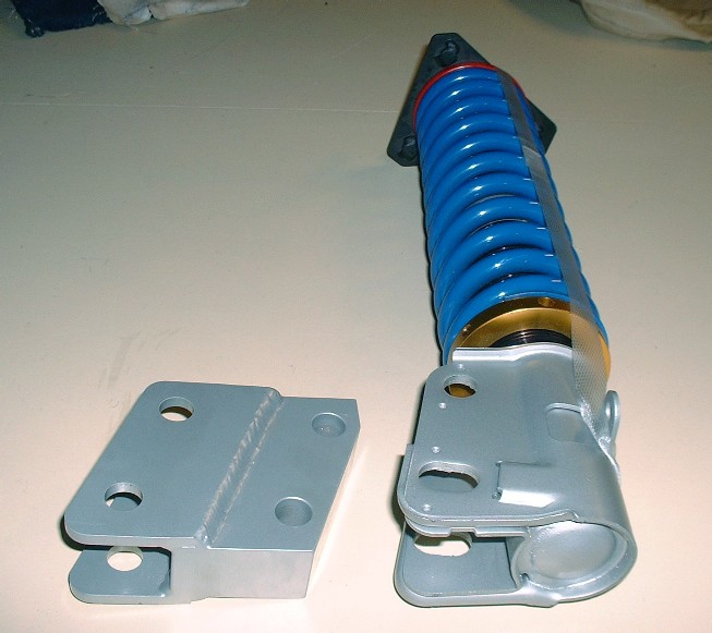
To finish off the assembly, all I needed to do was bolt on the lower strut adapters. They’re heavy suckers though so like I said, I’m going investigate shifting the upper mounts outboard instead of using these.
Here’s what they looked like after they were assembled. I used brand new M16 X 2.0 X 80 (10.9) bolts for them as well as for the ones that will attach the adapters to the tops of the knuckles. The old bolts just didn’t look right all pitted and rusty looking. At $2.50 each, they hardly even register on my cost spreadsheet.
I have KYB's in the rear too, and I went with a 350 lbs-inch spring rate as well.
They're stiff, but not too bad. It's hard to tell how much stiffer it made it, considering I also added poly, and solid cradle mounts at the same time. However, the ride isn't too bad, and I never bottom out which is good news since you're going to have minimal ground clearance. Although you have more leverage on the rear suspension, I would think 350 is a safe bet. Not to mention, I remember reading that anything over 350 isn't recommended for the damping capabilities of the KYB. Otherwise, you might have to go to Koni's.
You will still need the lower extensions even after moving the rear shock tower mounts out. I went out as far as I could which essentially used the original outer shock mount holes as the new inner holes and made a new plate on top of the strut tower that stretched the outer mount bolt out. I found that the upper frame rail came into play when turning the strut around so you will still need some extension from the lower solid piece you don't like. I made my own but they are pretty much the same size or maybe a bit narrower but not much. You have a good 4" on each side of the Fiero to extend out with that body you have. It being the same as mine and all......
If you want pics of how I did my strut tower extension, drop me a line and I can send them to you.
Dogcreek used 400 # springs on his LS4 build for about a week. The ride was entirely too stiff, and went down to 350 # springs afterward. It is still stiff, but not too much for our aging a$$e$.
I ran 250# springs on my '85 2M4 coil-over conversion. I like the ride. I also upgraded from the 13inch steelies to 17inch 45-series tires. The ride got quite a bit harsher after that change but I stick through the corners now much better than before.
[This message has been edited by Icelander (edited 01-19-2011).]
Thanks son (dhobbs), doublec4, Don, Tony, and Icelander for your input. If Tony says 350 lb spings aren't too stiff for his old creaky butt, then I guess I should be OK, but I hear you there doublec4 and Icelander... springs are only part of the equation. I'll be using polyurethane everything and much shorter tire sidewalls too so it all adds up. For Don, I get what you're saying about moving the tops of the springs too... there gets to be a point where the upper rail is the limiting factor... I hadn't thought that far into it yet. Looks like lower strut adapters might not have been a waste of money afterall! Yay?
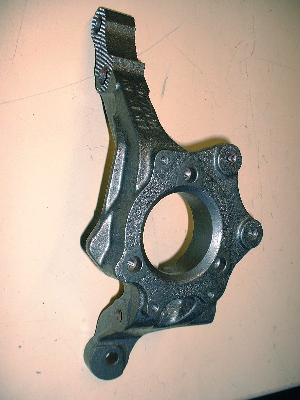
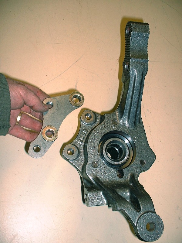
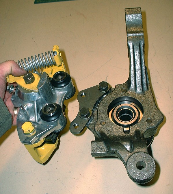
OK, back to the thread-building. I lied in my last post. For this story to maintain some semblance of order, the next step has to be about building-up the knuckles. Unfortunately I didn’t take any photos of the knuckles before they underwent a cosmetic surgery, but I’m pretty sure most of you know what a 23 year-old rusty knuckle looks like. Here’s what my ’88 uprights looked like once they spent the day at the “spa” with an exfoliation treatment and some anti-aging "cream":
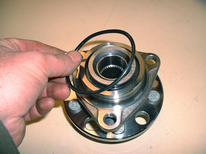
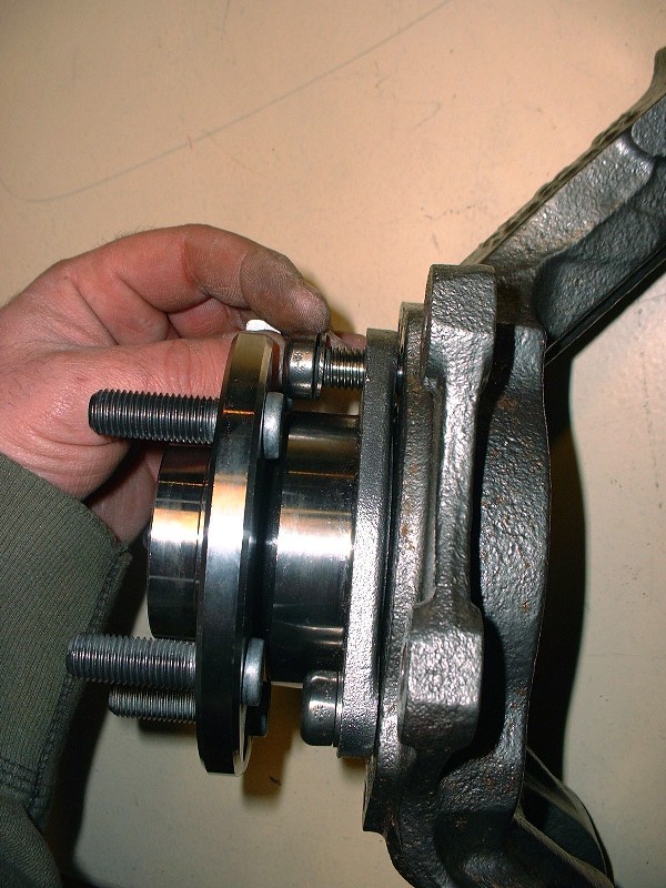
Because of the different rear suspension links, they’re considerably different than the pre-’88 rear knuckles. One thing GM kept the same on the rear though (luckily) were the wheel bearing assemblies. I bought new SKF units since the old ones had obvious axial and radial play in them. Nice shiny pieces. To help keep the road grime out of the inner bore of the knuckle, there’s a large O-ring that gets sandwiched between the bore and the bearing:
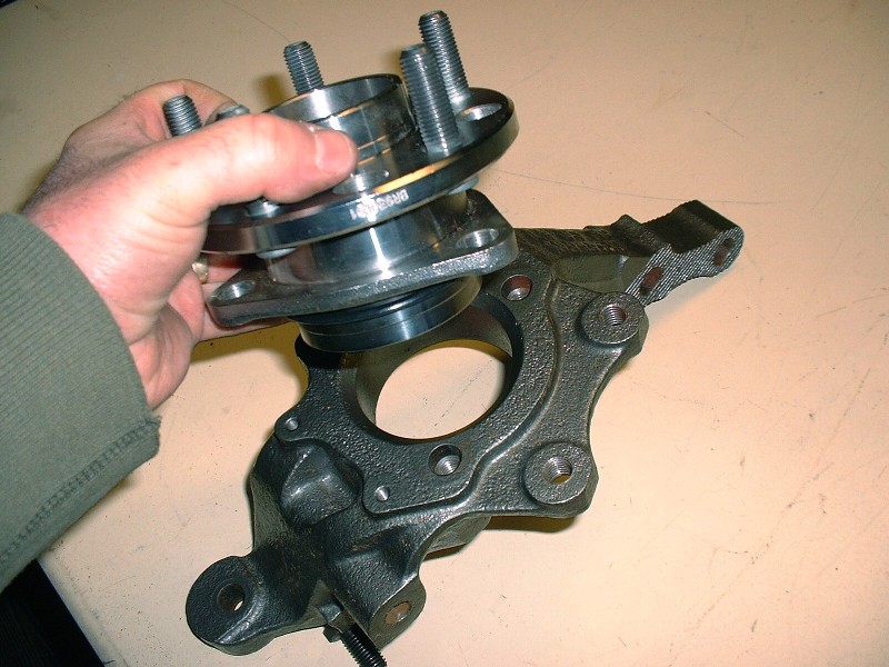
Then it’s a simple matter of placing the bearing on the knuckle and aligning the three retaining bolt holes;
Installing the bearing isn’t rocket science, but since I had the camera out I took a few extra pictures in case someone has never done this before. The bolts that hold the bearing are M12 X 1.75 X 40 and are installed through the road-side of the assembly. Of course the wheel flange would get in the way if it weren't for a machined semi-circle allowing access to one bolt at a time:
Once the first bolt has been snugged-up finger-tight, you have to rotate the flange on the bearing axis until one of other two holes line up, and repeat the process until they’re all finger tight. For the ‘88’s, the three bearing retaining bolts get torqued to 62 lbft.
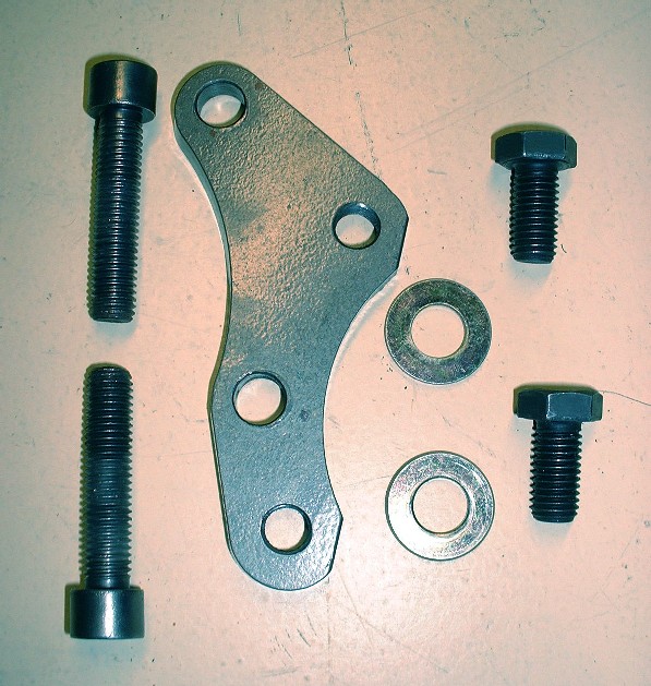
Next came the caliper adapters. I’m installing the ’88 – ’96 Corvette front 12” brake rotors on the back of my car, but plan to continue using the Fiero calipers for now. Lots of people have done this and it’s an inexpensive way to upgrade. That means though that the calipers have to be moved radially outwards (to accommodate the larger diameter rotors) AND offset slightly inboard to make up for the different offset in the Corvette rotor. That’s where the caliper adapters come in. I bought mine from the now defunct Fiero Addictions. Here’s a close up of one along with the hardware needed to bolt them to the knuckles:
These adapters aren’t marked left or right, or top and bottom, which means you have to orient them so that the caliper ends up being installed a little lower than the OEM location. If the adapters are reversed, the calipers would end up higher up on the knuckle and would interfere with the strut mount.
The reason the calipers are rotated with respect to their stock position is so that they clear the heads of the bolts that attach the adapter to the knuckle. I’ll edit this post and add the bolt specs later, but they get torqued to 74 lbft. Other designs for these adapters have now come out that get around rotating the caliper by using countersunk mounting bolts. I’m sure it’s a good design too, but anyone who’s ever tried to loosen countersunk bolts after years of road use will realize the shortcomings of this idea. The very large contact area under the countersunk bolt heads makes it very hard to loosen them without rounding off the small Allen-key type recesses used to turn them. I've always had bad luck and ended up drilling most of these type of fasteners out after lots of frustration, so I try to avoid them now.
Now the brakes are next.
[This message has been edited by Bloozberry (edited 01-21-2011).]
The brakes on the ’88 Fieros are different than for all the other years as pretty much everybody reading this knows. The overall diameter stayed the same at 9.7”, but GM finally upgraded the rotors to vented from solid discs. With this upgrade, new calipers were also needed to span the thicker rotor. The new calipers consist of two halves bolted together: one half is cast iron the other is cast aluminum. As mentioned earlier, my new brakes are going to consist of the stock ’88 single piston calipers for now, and vented 12” Corvette rotors. Theoretically, brake performance should improve since the calipers will be acting on the rotors with greater leverage. Practically speaking, I’ll have to wait and see how well it works out and upgrade to multi-piston calipers later if the performance isn’t up to snuff and if the budget allows it.
I didn’t get a good “before” picture of the entire ’88 caliper, so your imagination will need to be put to use again. I did however manage to save a picture of the aluminum half of one of them. Here it is in all its decrepitness:
I bought a couple of caliper rebuild kits, new rubber slider boots from TFS, sandblasted, primed, and painted the cast iron halves, and cleaned up and polished potions of the aluminum caliper halves. When it was all said and done, they came out looking a lot better than they started:
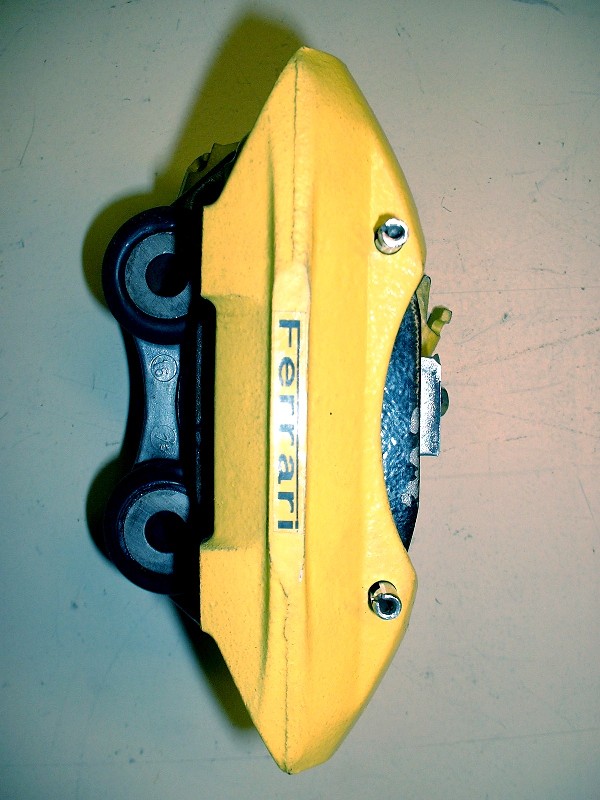
Some of you may frown upon the Ferrari sticker, but I’m not going to spend any time defending them, so don’t waste any bandwidth criticizing. I made them with a sticky-label-making machine and have used them on my 308 kit with great success. They stick like bubblegum to a running shoe on a 112* day… and even better when it’s cold.
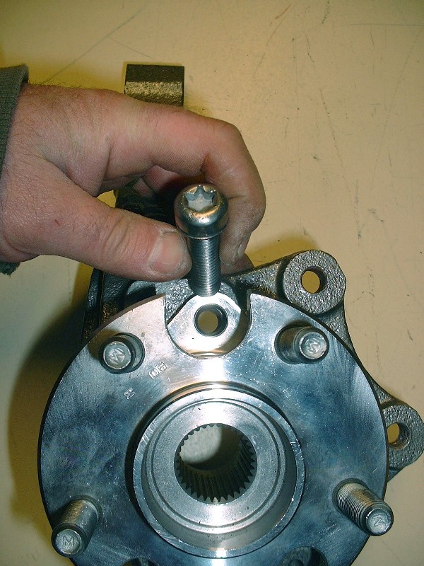
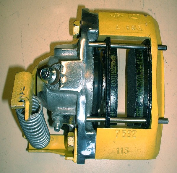
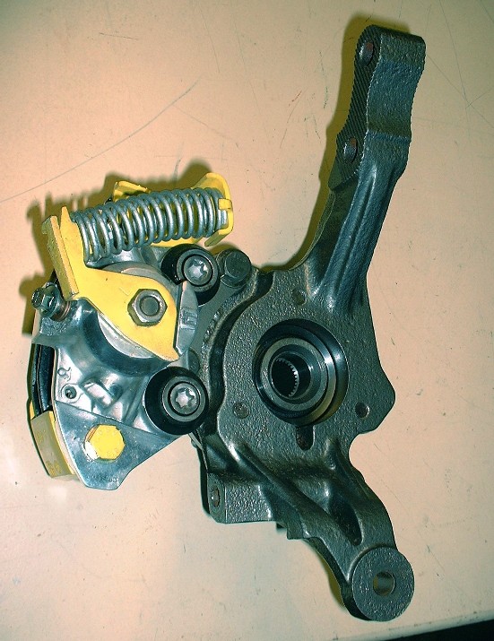
With the calipers completed, the next step was to install them on the adapter plates. You need a T55 Torx bit and a torque wrench set to 74 lbft to tighten them:
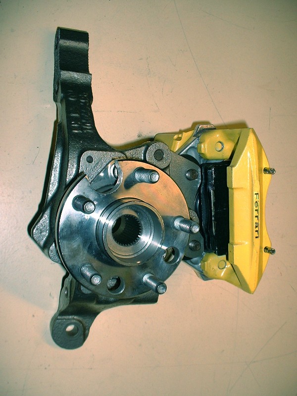
Here’s how puuuurdy they look once they’ve been attached for good.
And here’s the street side... I find they almost look like four piston calipers... if you squint.
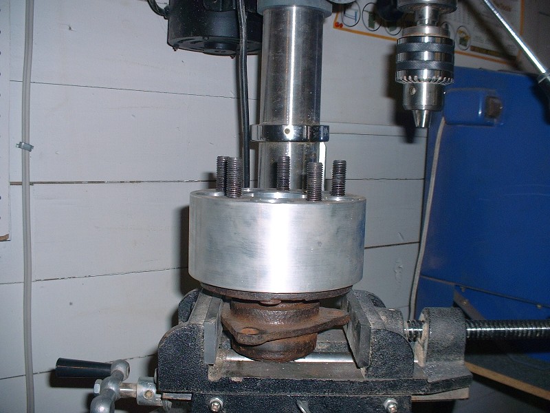
For the rotors, I got lucky when I went to the annual customer appreciation day at the local auto parts supplier. One of the many door prizes included four rotors of your choice… and luckily I happened to know of a car that needed exactly that. I think the owner was hoping that someone with a Geo Metro or a Hyundai Accent would win that prize. Now beggars can’t be choosers, so I did get the rotors but they weren’t exactly what the doctor prescribed. I only needed a little ingenuity and a bunch of time to make them just right. For starters, an old rear bearing assembly, an unused 3” wheel spacer and a drill press were the only bits of machinery I needed… any guesses what was wrong with my rotors?


 You have given me some ideas.