Looks good. That's the way I did my block as well. And it sure does leave a shavings mess.
Your kit is an improved later version than mine. Mine didn't come with the fancy alignment jig. I found that predrilling the block holes with a 1/2 inch bit made things easier to drill with Norms bits. I also used ARP (VW) studs instead of GM's stretch bolts. I like norms kit because it holds great and you can use GM head bolts or aftermarket studs. I've taken the heads off twice and they held fine under each re-torque.
A new kit has also been developed by a fellow named Jake in Ontario, Canada. His kit is a one piece stud: http://www.northstarperformance.com/sgstuds.php He's on the Cadillacforums.com site and is not in favor of the inserts of course.
Both kits seem to work extremely well compared to GM's approved time serts. I think its good insurance to do Norm's inserts or Jake's studs to your block regardless if you have a head sealing issue or not.
You might want to consider using Cometic head gaskets (provided you have the 94-99 N*). They will not deteriorate like the GM graphite or Felpro gaskets under the shrinking and expansion of the heat cycles in the water jacket areas. I have them on my N* and they seal nicely. Expensive motor isn't it!
Thanks for the comments mccanda, Isolde, Joe & Hugh.
Dave: the alignment jig was extra... it retails for $95 separately but if you buy it with the basic kit, the total comes to $395 for both so there's a savings to be had. I think it was worth the extra money to get the drill and taps lined up properly.
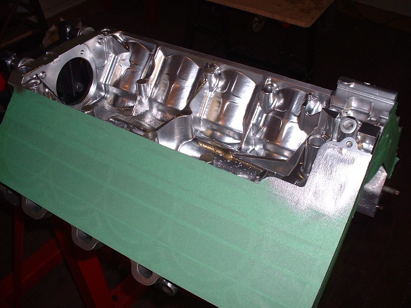
At this point with all the machining, polishing and tweaking done, the engine was finally ready for a good wash... I was getting tired of all that burnt oil-varnish ruining my photos. I took the block to a different machine shop here that specializes in rebuilding cylinder heads, which I knew from experience could wash the block in a high-pressure hot water and detergent machine that wouldn’t ruin my polished exterior. The results were great and the block came out looking better than brand new. Over the course of the next few photos you’ll see the difference.
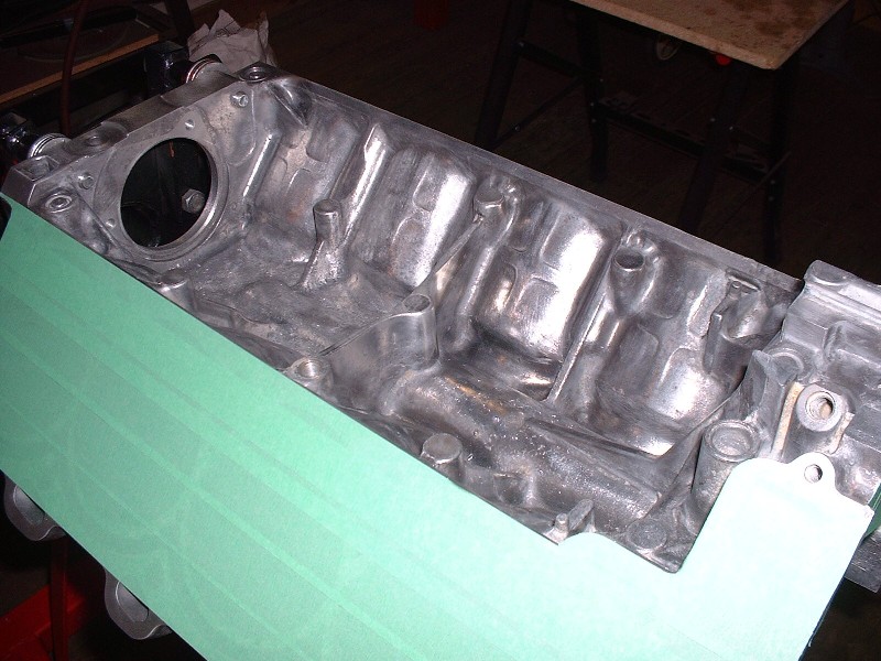
One thing I decided I wasn’t going to do was polish anything that wouldn’t be seen, like the intake valley (or the lifter valley if it were a pushrod engine). After the wash, the valley was super clean but still quite pitted so I wanted to protect it from future corrosion as much as possible. The dreaded white powder starts in the little pits and grows outward so the idea is to seal off the pits with paint to keep water and other contaminants out. Here's the bare valley:
I masked off the cylinders and bought some Duplicolor Chrome paint… this stuff is amazing… looks great and dries fast. I think you’ll agree. It does smudge if oil contacts it once it's dry though, so if anyone reading this plans on spraying their entire engine with it, it will need to be clearcoated to keep the sheen.
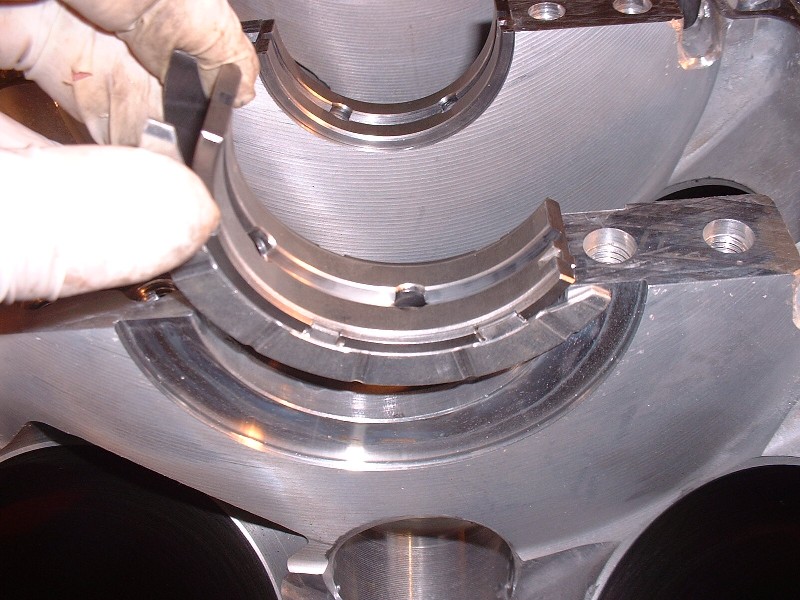
With that little loose end tidied up, I could turn the engine over on the stand and start working on building up the lower end. The first thing was to measure the main bearing clearances so in-went the bearings. This is #3. You’ll notice it’s the thrust bearing with the side wings. I wear gloves when I handle bearings because finger grease is acidic enough to etch the finish on them if you’re not careful.
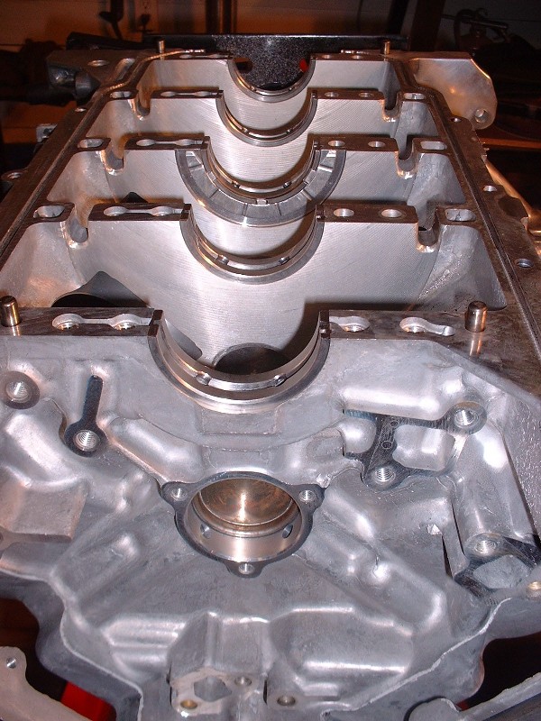
Here’s a pic of all the bearings in place (notice the clean innards?). Like any other engine, they go in the block dry. I lubed up the surfaces that contact the crank with a thin layer of motor oil before laying in the crank, but nothing thick like assembly lube at this point since I didn't want to throw off measuring the clearances.
Next up was laying the OEM neoprene case-half seals and a piece of green Plastigauge on each of the main crank journals. The whole thing had to come apart again to read the Plastigauge, so no sealant was used on the case-half seals at this point. In retrospect I could have left the seals out at this point, but I figured they couldn’t do any harm. Later, I would discard these seals altogether and replace them with a new engine sealant that GM recommends instead.
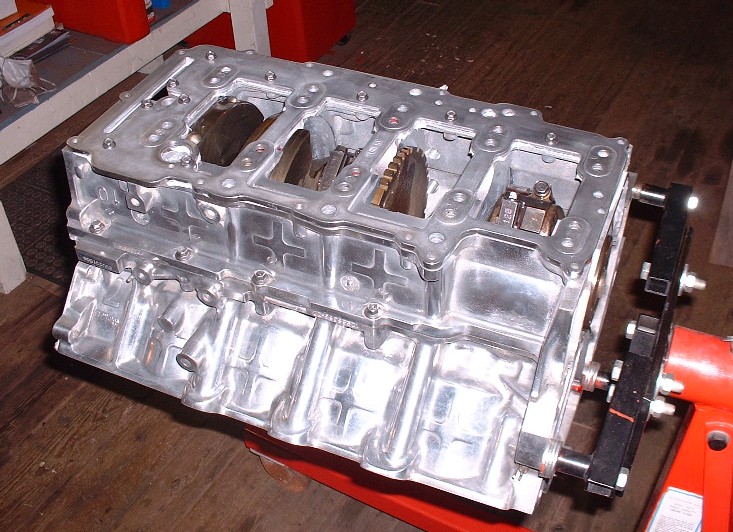
The lower bearing halves were installed in the lower case half, and the lower case half was then installed carefully onto the upper case half. There are four tight fitting guide pins that make installing the lower case half difficult without a rubber mallet.
Because the main bearing cap bolts pass through the windage tray and the oil manifold, these parts must be assembled onto the lower case half as well before finally installing the bolts. Here’s the oil manifold sitting there awaiting the windage tray installation.
And here’s the windage tray in position and the main bolts (all 20 of them) being set in place. Unlike the connecting rod cap bolts, these are not TTY (Torque To Yield) and can be reused.
[This message has been edited by Bloozberry (edited 05-12-2010).]
After drilling out the factory threads, the next step was to tap the new holes for the inserts. Norm’s kit also included the tapping oil and the Locktite to secure the inserts in place.
Be sure you use an appropriate solvent to clean all the tapping oil out first.
I'd suggest "maximum strength retaining compound" (don't know the number right off) as opposed to regular red Loctite.
Originally posted by IXSLR8: Both kits seem to work extremely well compared to GM's approved time serts. I think its good insurance to do Norm's inserts or Jake's studs to your block regardless if you have a head sealing issue or not.
You might want to consider using Cometic head gaskets (provided you have the 94-99 N*). They will not deteriorate like the GM graphite or Felpro gaskets under the shrinking and expansion of the heat cycles in the water jacket areas. I have them on my N* and they seal nicely. Expensive motor isn't it!
The Y2K engines use the same head gasket. I think it was used through '04 or '05.
Unless your had a problem with losing bolt tension or head gasket seal due to relaxation, creep or corrosion of the original threads in the block, or you are going to run 30 psi of boost, timeserts are quite sufficient.
The problems dealerships have with them are that the engines that need inserts are so badly neglected that they've deteriorated so much that they need bigger inserts than the timeserts.
IE, if you don't have a detectable porosity or corrosion problem already, you will almost certainly not need anything more than timeserts. Even at that, you only need timeserts for durability of the threads after multiple torque cycles.
Originally posted by Bloozberry: Finally, here’s what the insert looks like fully threaded in and locked in place. Pretty deep down in there eh?
Enjoying the slide show so far?
Deep set headbolt threads in the outer wall of an open-deck block keep the cylinder wall loaded in compression under all circumstances and help the cylinder keep a more consistent shape. This helps ring seal and therefore both power and economy. This was (I think) the first time GM used this configuration (although Honduh may have used it earlier in the B-series).
Originally posted by Bloozberry: And here’s the windage tray in position and the main bolts (all 20 of them) being set in place. Unlike the connecting rod cap bolts, these are not TTY (Torque To Yield) and can be reused.
The bottom end of the Northstar is extremely robust. I believe that Alan Johnson of CHRF uses stock main bolts in all of his engines at any power level (including 2000 HP Methanol burners).
BTW, I'd torque the main bolts first, THEN tighten the smaller bolts that help seal the oil manifold.
[This message has been edited by Will (edited 05-13-2010).]
As for Will... thanks too for your comments... I was wondering how long it would take before you chimed in! I'll address your comments one at a time:
a. The red Loctite I used was supplied by Norm in his kit, I too forget the number, but I have no reason to believe it he would include it in the kit if it wasn't strong enough... (keeps fingers crossed).
b. I know your comment was directed at IXSLR8, but the point I was making about Timeserts is that they are just too expensive. I don't think anybody questions their effectiveness on engines that meet the necessary minimum requirements, but for the cost of the the tool kit, it's no surprise there are equally good alternatives showing up at 40% -50% cheaper.
c. Interesting theory for the deep headbolt threads. I had just assumed that they were made deep to enable the use of longer steel bolts that would stretch more easily than shorter ones and come closer to matching the rate of expansion of the aluminium block and heads.
d. I'm not sure what difference it would make to torque the main bearing bolts first rather than the oil manifold bolts or vice-versa. The oil manifold bolts only retain the manifold to the lower case-half, whereas the main bolts secure the lower case-half to the upper case-half. Perhaps you meant that you'd torque the main bolts before the case-half perimeter bolts. That makes more sense to me, and is also the order which the manual calls for them to be done. In my picture, you can see one perimeter bolt, but I had only just tightened them finger tight.
Large bolted interfaces should be tightened down from the center outward. Thus my suggestion regarding the main bolts.
Did you check ebay for a used Time Sert kit? I will agree that the kit itself is expensive. I did my main bolt holes on a mill and thus only needed the insert installation mandrel... which was something like $150. Absurd.
A 3" steel bolt will expand with the coefficient of thermal expansion of steel, the same as a 6" bolt. There are many reasons to use longer bolts.
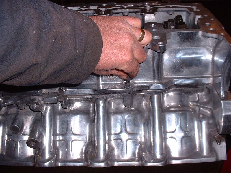
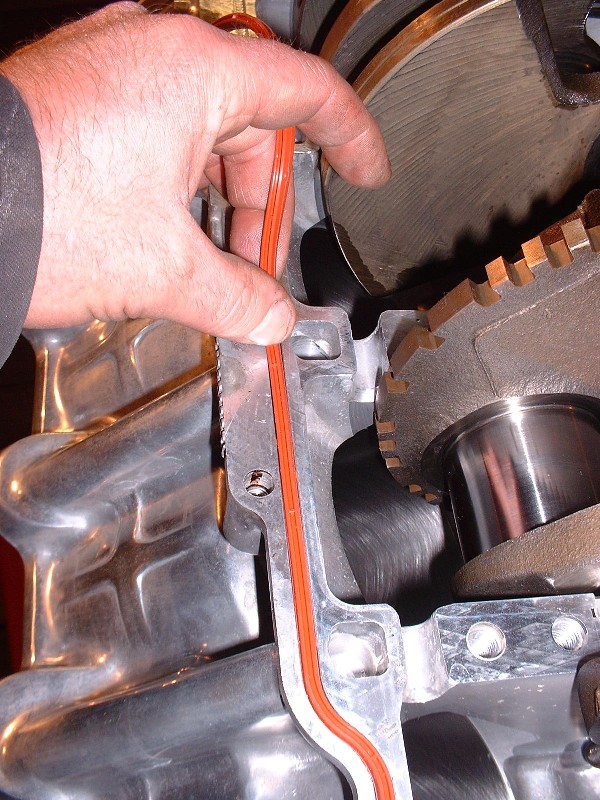
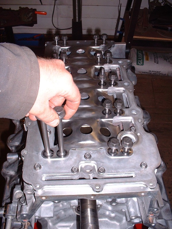
The perimeter bolts I mentioned above are a series of smaller 8mm diameter bolts that secure the lower case-half to the upper case-half next to the seals. Here’s a picture of where the are.
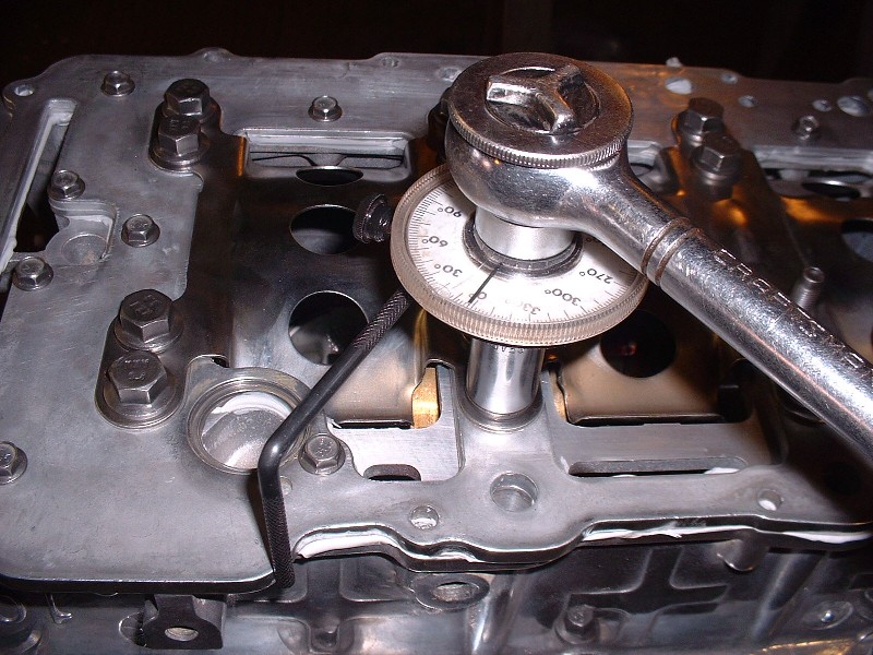
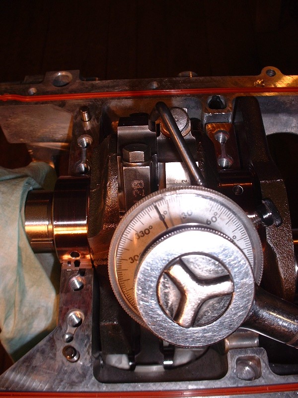
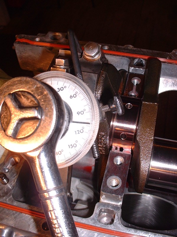
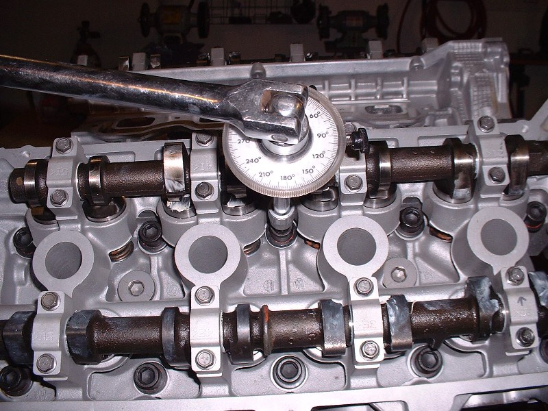
Before the perimeter bolts are tightened, the main crank bearing bolts have to be torqued to spec. The instructions call for a nominal 18 lbft to be applied initially in a particular sequence, then followed-up by turning each bolt an additional 65 degrees. To do this accurately you need an angle gauge on your ratchet wrench. For those who’ve never used one, they’re quite simple… they just attach between the wrench and the socket. There’s a little adjustable arm that sticks out to one side that you must butt up against a steady surface like the side of the block, then you zero the gauge to zero by spinning the face up with wherever the needle is. The last thing you do is turn the wrench, which spins the needle until you reach the desired number of degrees.. The little arm keeps the dial face from spinning along with the needle. It’s really quite simple actually. Lastly, the perimeter bolts get torqued to 89 lb-in.
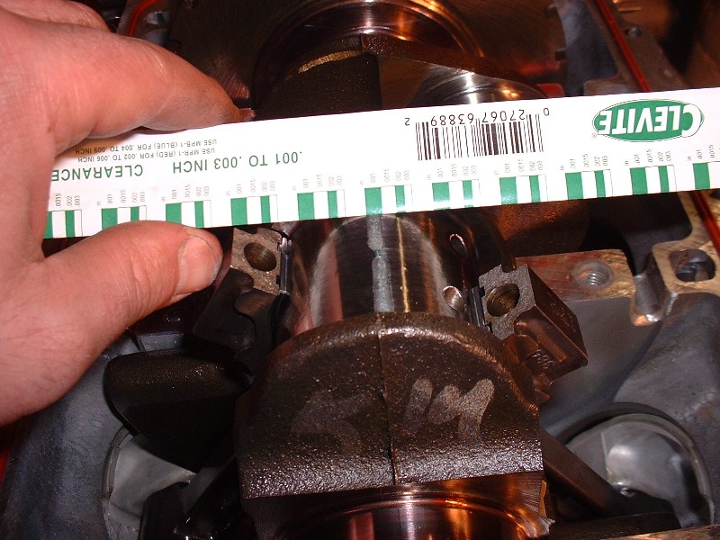
Once again, this is all just to check the main bearing clearances with the Plastigauge, so it’s all got to come apart after waiting about two minutes for it to take a final “set”. The Plastigauge gets squeezed between the bearing surface and the crank journal leaving a line of varying width depending on how tight the clearances are. Here’s what the lines looked like on the lower case half bearing shells.
I took my measurements from the marks left on the crank journal. There’s a little scale on the packaging for the Plastigauge that allows you to measure the clearance in accordance with the width of the squished gauge. The spec calls for 0.0006” – 0.020” (yes… that’s six ten-thousandths) whereas mine measured from 0.0010” to 0.0015” so I was happy.
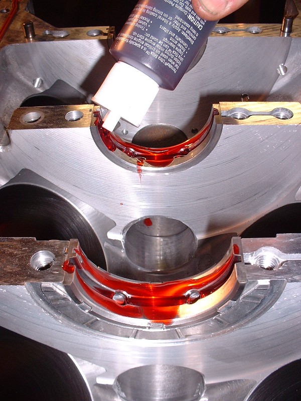
Once you’re done, you can’t forget to clean the Plastigauge off of the journals and the bearings. I find WD40 on a soft cloth does a good job of dissolving it since it gets stuck on there pretty good. You don’t want to use a fingernail on the bearing surface, that’s for sure. Next up is the final crank installation so a good healthy dose of assembly lube on the bearing surfaces is in order… I’ve used the Clevite and the Permatex assembly lube with equal success… this stuff would make a Vampire think about going for a tall cool one.
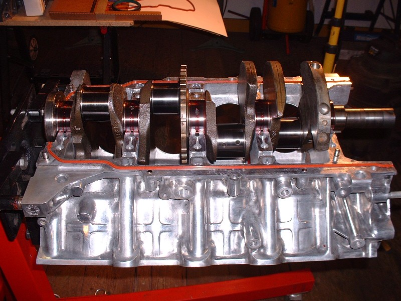
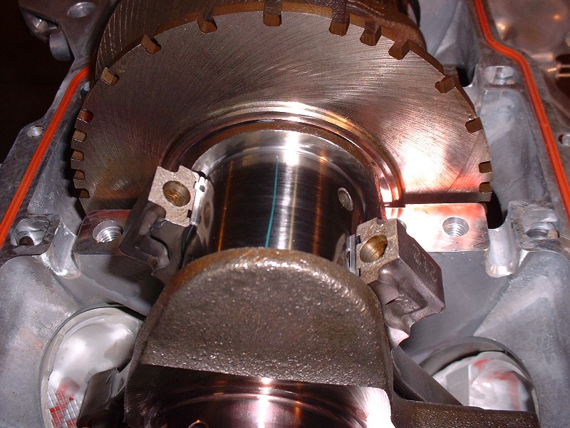
A final cleaning of the crank journals and Voila!… the crank finds it’s permanent home. A quick spin to lube up the journals all the way 'round and I was ready for the crank end-play measurement.
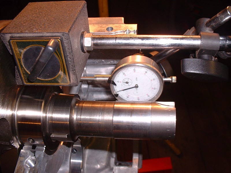
Crank end-play or float is the amount of fore and aft movement of the crank in the block along the axis of the crank. On a manual transmission it's especially important since everytime you press in on the clutch, it shifts the crankshaft forward along it's axis with a fair bit of pressure. Too much movement and you begin to throw the connecting rods off of their intended plane of movement. The #3 main bearing with the thrust surfaces (shown earlier) is what determines the amount of crank end play. The way I measured this was by sticking a magnetic dial gauge to one of the crank’s counterweights, with the gauge plunger on the stationary bearing web. Then I pushed the crank as far backwards as possible with a small pry bar, zeroed the gauge, then pushed the crank as far forward as it would go and took the measurement. The spec calls for between 0.002” to 0.019” and mine was 0.008”.
With everything in order and within specs, the lower case half was re-installed, along with the oil manifold plate, windage tray, main bearing bolts and perimeter bolts for what was supposed to be the last time… ahhh… ignorance is bliss.
Not sure how many of you N* owners frequent the CadillacForums.com site.
Here's an interesting thread on head gasket failures, GM timeserting and the use of other inserts such as Norms. I'm not making a particular statement but rather showing a link where you can find more information on inserts, head gasket failure and related info from a fix perspective:
With no practical experience I can only theorize. I suspect that norms are better than serts. I would think that even better would be studs. Especially if removing the heads a few times. Can the rwd head gaskets be installed on a fwd?
Before the perimeter bolts are tightened, the main crank bearing bolts have to be torqued to spec. The instructions call for a nominal 18 lbft to be applied initially in a particular sequence, then followed-up by turning each bolt an additional 65 degrees. To do this accurately you need an angle gauge on your ratchet wrench. For those who’ve never used one, they’re quite simple… they just attach between the wrench and the socket. There’s a little adjustable arm that sticks out to one side that you must butt up against a steady surface like the side of the block, then you zero the gauge to zero by spinning the face up with wherever the needle is. The last thing you do is turn the wrench, which spins the needle until you reach the desired number of degrees.. The little arm keeps the dial face from spinning along with the needle. It’s really quite simple actually. Lastly, the perimeter bolts get torqued to 89 lb-in.
Be sure to go back and RE-torque the sequence to 18 ftlbs BEFORE applying the 65 degrees. The first bolts in the sequence WILL relax as you tighten down the bolts around them.
I forgot to mention that Will... thanks! This is very true whenever torquing anything with a torque wrench.. always go back and and retorque all of the fasteners a second time to pick up the slack on the first fasteners created by the last ones. Even though this isn't mentioned in the assembly manual, it's common sense. In my case, I think I put another 30* or so on the first few main bolts before the torque wrench "clicked" at 18 lbft the second time around. If I hadn't rechecked, then clearly the first few main bolts would have been under torqued by 30* when all was said and done.
With the lower case-half installed, I could finally move on to installing the sparkly new pistons. Or could I? Within minutes of having torqued the main bearing bolts for the second time, it dawned on me that there was no way I was going to be able to install the connecting rod caps and bolts with the lower half of the engine installed. There just isn’t any room… especially with that windage tray in the way. Rats! I got ahead of myself.
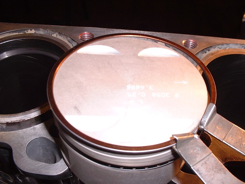
Before removing the lower end again, I decided I’d turn the engine upright (something you can’t do with the lower case-half off without the crank falling out!) and measure up my compression ring gaps. If you’ve never rebuilt an engine before, when you measure the ring end gaps you have to ensure they’re level in the cylinder or they’ll throw off the measurement. The best way to do this is to slip a ring into the cylinder and push it down an inch or two with an upside down piston. It’s easy to make sure the piston is level since there are all kinds of ring lands to line up with the deck surface.
Once the ring is in level, pull out the piston and measure the ring gap with a feeler gauge. You have to do this with all 32 rings (1 top ring, 1 middle ring, and two oil scraper rings per cylinder) and make sure you dedicate each ring to the cylinder that it was measured in. Not all cylinders are exactly the same diameter, and not all rings are exactly the same size, so to file as few ring gaps as possible, I measure all the rings starting with the lower scraper rings first, then swap around tightest and loosest rings until I get the end gaps to match as close as possible between all of them. The oil scraper ring end gaps on a Northstar are allowed to be 0.010” to 0.030”. Once I was finished moving them around for the best fit, mine were from 0.010” to 0.013”… not bad at all. Then I move on and do the same for the two compression rings. By mixing them up I was able to avoid any ring gap filing and therefore maintained the nice, even, factory square edges.
Next up is to install them, starting with the lower oil scraper ring, the spacer, upper oil scraper, lower compression, and then upper compression ring. You have to install them in this order because the rings get installed from the topside of the piston and you can’t stretch a lower ring over top of an upper ring if it were installed before the lower ring… it just doesn’t work. The oil scraper rings are easily installed with your fingers…
…but the two compression rings are best installed using a ring expander.
I bought a master engine rebuild kit that basically comes with everything you need to rebuild an engine. It’s the cheapest possible way because to buy the parts individually you’d pay easily 1.5 to 2 times as much for the same parts. I ended up buying my kit from a company called EngineTech because they were one of the two companies that offered 0.25mm oversized pistons that I could find. There were choices between hypereutectic and coated pistons from other companies, but as far as my budget was concerned, I thought it best to spend the money on other things.
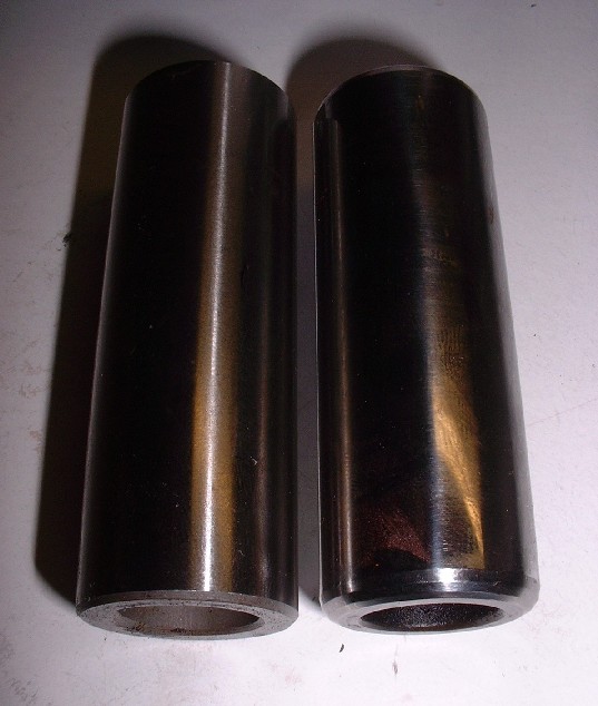
I was happy with the quality of the parts from EngineTech except for the piston wrist pins. They weren’t consistently the same length, nor were they consistently chamfered at both ends. Here’s an example of two pins from the same kit. To be honest, I’m not sure I would have noticed except that when I went to install the retaining clips, 5 of the wrist pins were too long. I ended up having to shorten and/or chamfer all 8 pins to one degree or another.
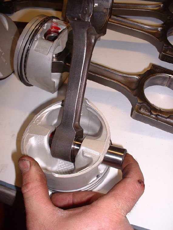
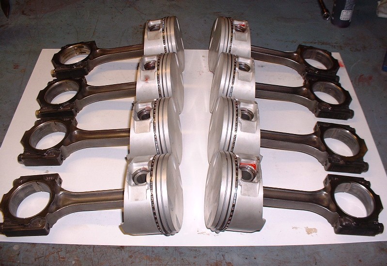
Once that bit of business was taken care of, I was able to assemble the connecting rods to their respective pistons… (note the ugly busted knuckle… the result of losing a fight with rounded bolt on a customer’s car)
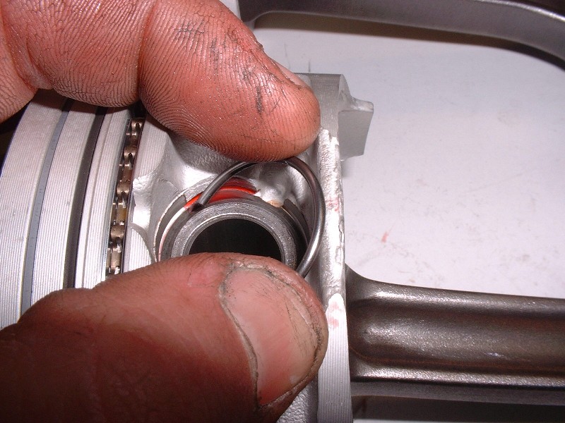
… and install the spring clips to retain the wrist pins… (I know, I have an ugly thumbnail too… from flipping the nail on another customer’s car… ouch!). You can see from this photo why too long or improperly chamfered wrist pins cause a problem. You can get one spring clip in place, but you just can’t seat the second one.
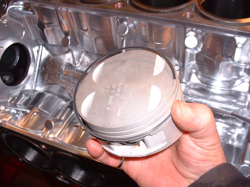
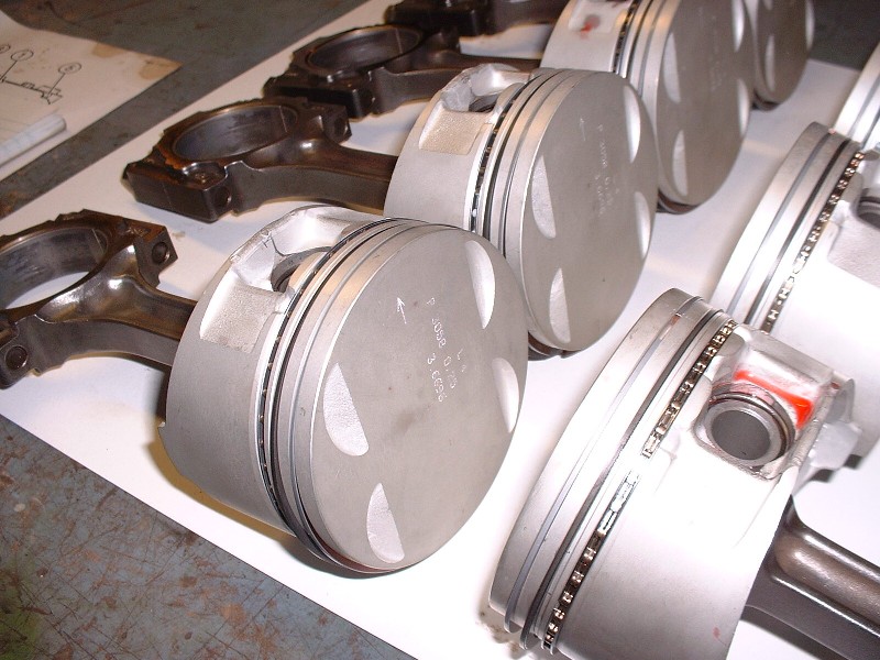
Finally, here’s a couple shots of the completed rods and pistons ready to be installed in the block… well, once the lower case-half was removed again.
[This message has been edited by Bloozberry (edited 05-18-2010).]
No need to reply to the post above from me. We have met. This looks like a great project for you, great workmanship you have. I still think about the go-cart. Someday I will make plans to visit you at the "old farm" when cruising the valley. My fiero is painted black and is a fifty footer. Bye for now.
One thing I forgot to mention in my last post is that it’s a good idea to measure the side clearance of the top two piston rings too. You just slip a feeler gauge between the piston ring and the ring land on the piston itself. The clearances are pretty tight for this measurement: 0.0016” to 0.0037”. It’s hard to find feeler gauges less than 0.0020” thick although a more expensive set I bought for this engine had a 0.0015” feeler. I could fit the 0.0020” in all of mine but not the next size up 0.0025”, so all was good.
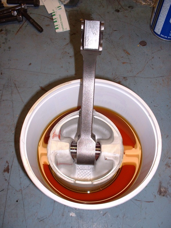
So I turned the block upside down again, removed the lower case-half, and began installing the pistons and connecting rods to measure connecting rod bearing clearances. The first thing to do is to make sure the rings are well lubricated. I get an old margarine container, put an inch or two of oil in the bottom, and dip the whole piston top in it. It’s messy, but effective. Now's the time to lube them up since there’s no need to take the pistons out again after checking the bearing measurements.
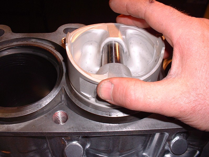
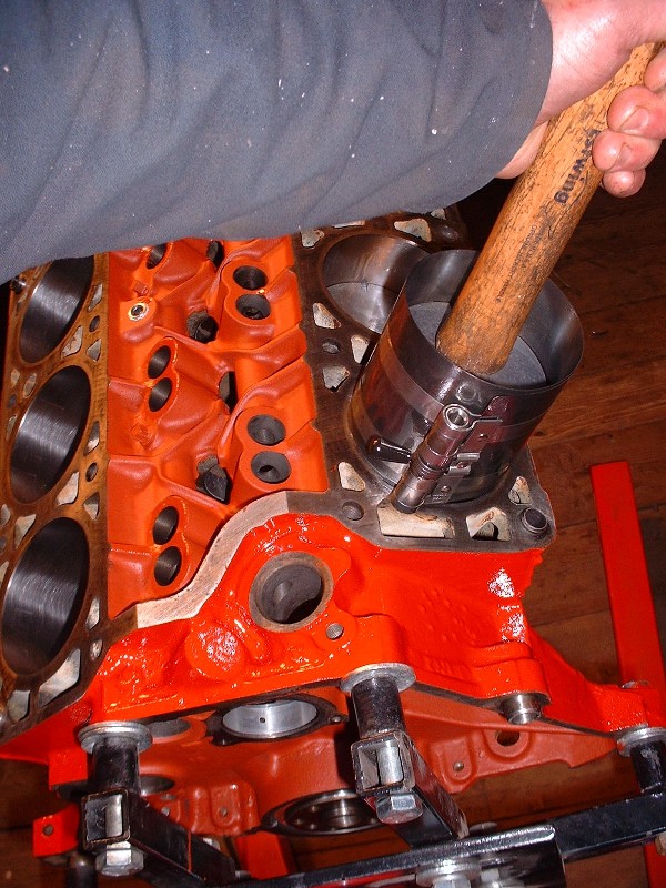
To compress the piston rings so the pistons will slide into the cylinders, I use a locking band-style ring-compressor instead of the pliers-style. I couldn’t take any pictures at this stage because it took too many hands to install the pistons with the block upside down, and besides, I was full of engine oil! For those who’ve never done it, here’s a picture of me installing a Fiero 2.8L piston in a block that’s right side up. The ring compressor just squeezes the rings flush with the piston OD so that they don't hang up on the deck when pushing the pistons in. The compressor has to be held up tight against the block deck or else the super thin oil scraper rings slip out of the crack and expand prematurely preventing you from going deeper. It's not bad right side up, but rather frustrating to do up side down on the N*.
Of course the Northstar pistons and connecting rods are uni-directional so they must go on in a particular orientation. Here’s a picture of some virgin Plastigauge on the rod journal prior to bolting on the caps.
Before sticking the connecting rod cap on, there’s an important thing to remember when rebuilding a Northstar. The connecting rod bolts are Torque to Yield (TTY), meaning that they get torqued so much that they are irreversibly stretched the first time you torque them, and then if you remove them, they’re no good anymore. They’re also $17.14 each times 16 of them equals $300 after taxes, so you don’t want to use up your new ones to check your bearing clearances or it’ll be a costly mistake. I reused the old bolts to check the bearing clearances. Once again, you install the rod bolts, torque them to a nominal 18 lbft, click on the angle gauge, set it to zero…
… and torque the crap out of it until you reach a whopping 110* more twist on the bolts. It not only sounds like a lot, it feels like a lot. You can only do two at a time since you can’t turn the crank without smearing the Plastigauge, and you’d never get the other caps on without turning the crank.
So two by two you torque the caps, remove the caps, check the rod bearing clearances, clean off the Plastigauge, reinstall the caps using your new rod bolts, and torque them up a final time. Then you move onto the next pair of rods. Here's more squished Plastigauge.
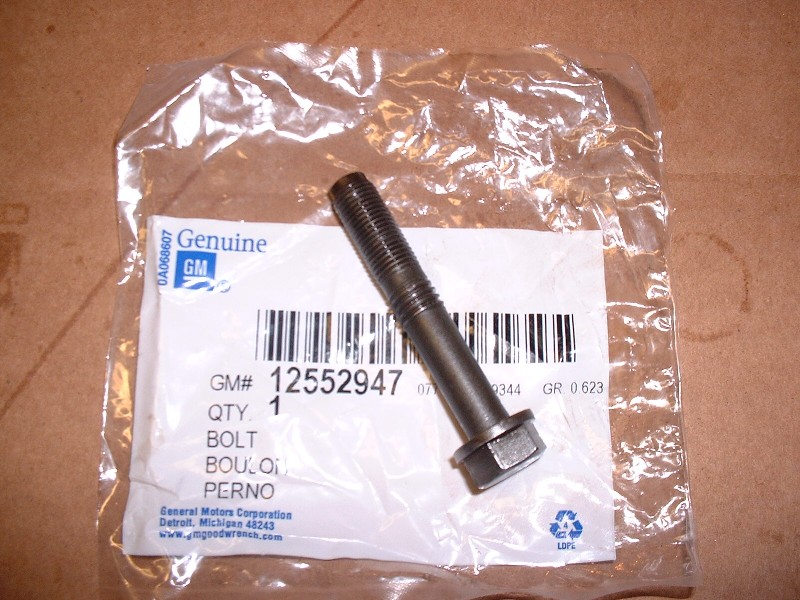
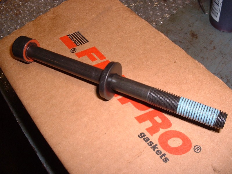
Here’s a pic of the rod bolts (GM p/n 12552947). I thought I’d include it because of the strange threads. It’s only the fine threads at the end of the bolt that engage the connecting rod, so I’m not exactly sure of the reasoning for the coarser threads halfway down. Just bizarre enough to make you think long and hard about going to the hardware store and buying some generic rod bolts at a quarter of the cost.
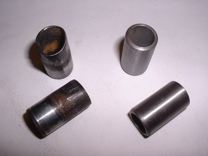
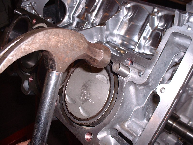
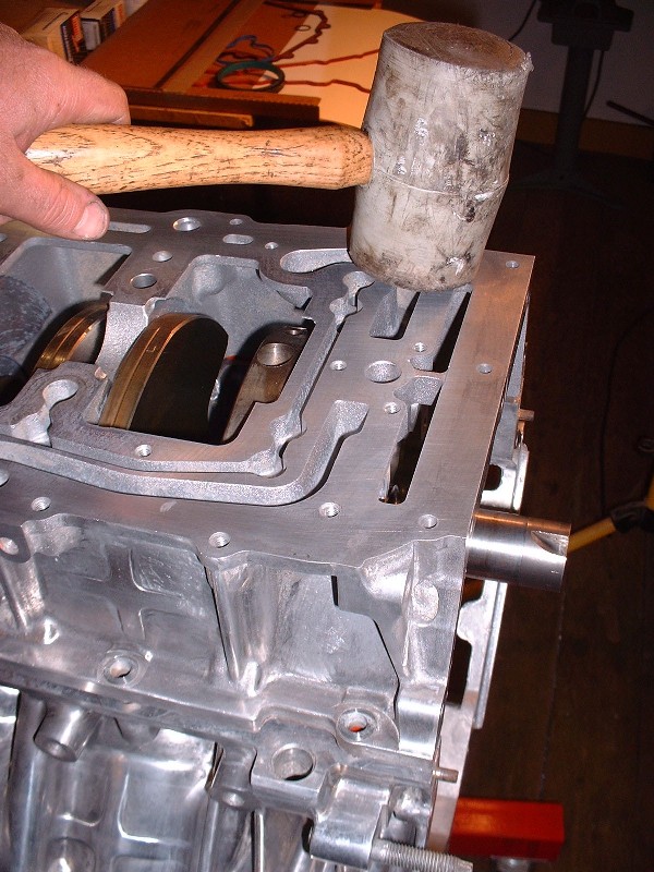
With the pistons installed, the next step was to retrieve the heads from the machine shop! Yay! In preparation for this, I knew I needed new cylinder head alignment dowels as previously mentioned, so I took a trip to a buddy of mine’s who has a lathe. Within an hour or so, he had a new set of four nicely turned for me for $25 instead of $75 from the dealership.
A few quick hammer taps and I was ready for the heads.
Originally posted by Bloozberry: I reused the old bolts to check the bearing clearances. Once again, you install the rod bolts, torque them to a nominal 18 lbft, click on the angle gauge, set it to zero…
… and torque the crap out of it until you reach a whopping 110* more twist on the bolts. It not only sounds like a lot, it feels like a lot. You can only do two at a time since you can’t turn the crank without smearing the Plastigauge, and you’d never get the other caps on without turning the crank.
Sounds like the rod bolts really were torqued to yield.
You're probably right there Erik. The bolt would be at it's smallest cross section in the bottom of the coarse threads, so that would be the weakest point.
Hmmmm… I keep getting ahead of myself. Before I could turn the engine upright and install the alignment dowels, I had to bolt the lower case-half on again. This time, luckily, I had done a little more reading here on PFF about sealing the case halves properly. I mentioned before that the original way was just using the orange neoprene seals. I guess GM found that they didn’t work very well so at some point a few years back they recommended following up with some anaerobic sealant in the seal grooves, then installing the seal, and then more anaerobic sealant before joining the two halves together. Most Northstar rebuilds on PFF to date have used this method with good success.
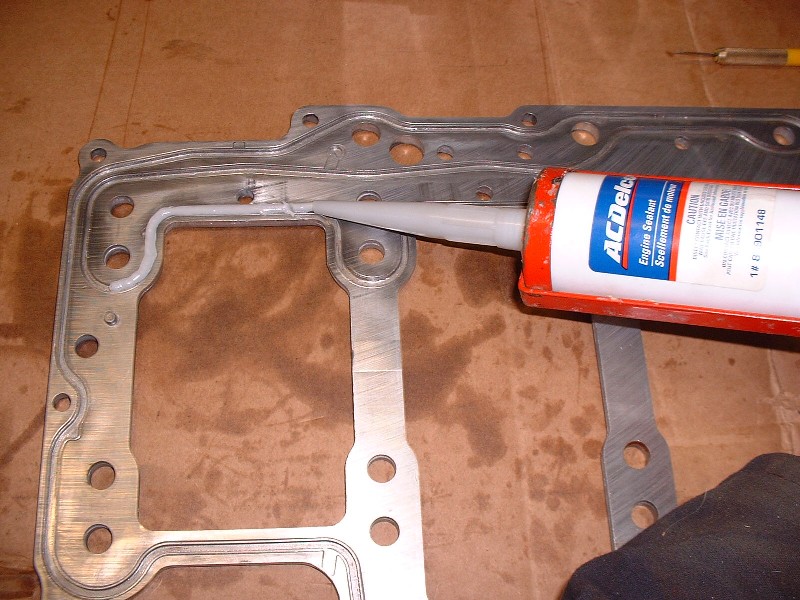
I, on the other hand, had downloaded and was following AJxtcman’s instructions for reassembling my engine. In it, GM calls for a particular sealant which I tried to buy but was told that the part number had been superseded to AC Delco p/n 88901148. The instructions make no mention of the neoprene seals at all, instead, they say to fill the machined grooves that the seal sat in with this new engine sealer. So I did.
The sealant costs $17 and comes in a 1/3 length caulking-gun tube and has enough sealant to do about 90% of what you need… it’s like they know and they do it on purpose. It’s kind of a grayish putty-like silicone and blends in reasonably well with the color of the aluminum. Once you fill the grooves you have a maximum of 20 mins before it skins over and becomes useless. It’s plenty of time. So once the lower case-half was gooped up, I flipped it over and onto the block. Next came the oil manifold plate.
GM recommends replacing the oil manifold plate and I now know why. It takes more time than it’s worth to clean the OEM silicone out of the serpentine grooves. Once it was done though, it got the same treatment as the lower case-half… AC Delco engine sealant in all the grooves with enough to stick up about 3mm above the surface of the plate.
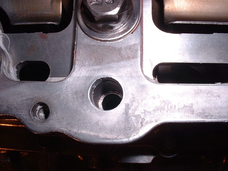
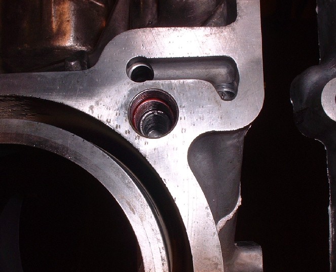
With the oil manifold plate installed, next came the windage tray (again), and finally all the main bearing bolts for the last time (**crosses fingers**). One thing to be watchful of once everything is torqued back into spec is that the engine sealant doesn’t ooze into the oil drain-back tubes on the side of the block and plug or restrict them. The oil drain-back tubes carry oil from the heads down through the upper case-half, lower case-half, oil manifold plate and finally into the oil pan. All of these mating surfaces except the heads have engine sealant applied to them so you’ve got to reach down with a thin bladed screwdriver or dentist’s tool into each tube after every step and clean up any sealant that squeezes in them. Here’s one of the tube holes I’m talking about. I had to clean sealant out of about three tubes.
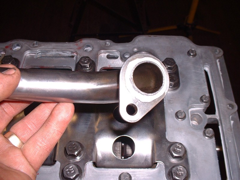
Another frustrating thing about the ’97 block is that the oil manifold plate doesn’t come with a replaceable oil pick-up tube seal. Some earlier-year blocks do, but GM probably decided that since you should replace the manifold plate, then there was no purpose to making a replaceable pick-up tube seal. Before I ruined mine digging it out, I read the list of contents of my master rebuild kit and it included the seal, so I went ahead and tore the old one out of the plate. Only after I had done that did I actually look for the seal only to find an O-ring that didn’t fit. The later blocks use a molded-in-place neoprene-like seal. To make a long story short, I ended up using more engine sealant around the pick-up tube and sticking it in place. This is an area where you can’t afford to have leaks because the oil pump would much rather suck air in through that leaky joint than try to suck that thick oil up from the pan.
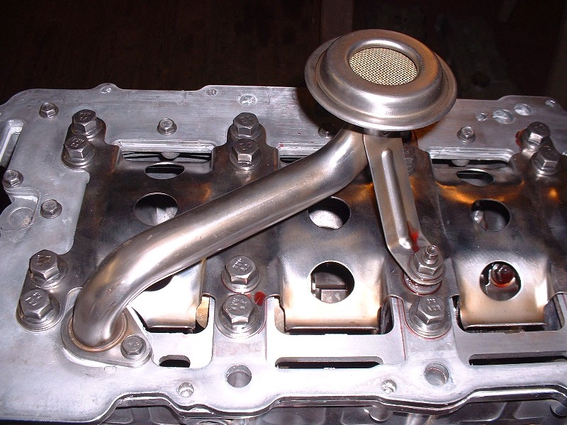
Here’s the pick-up tube bolted in place. Notice too if you’re building your own Northstar that one of the main bearing bolts is actually a stud… that one goes on one of the #3 bearing caps so you can bolt the oil tube to it later. Finally I treated the oil pan with the same engine sealant and tossed out the orange neoprene seal. The oil pan bolts get torqued on is a particular sequence just like everything else. OK, now I was ready for the heads.
My personal perceptions and comments on these options are: 1. The CHRFab Holley works, but is crude compared to OEM computers. 2. Ryan Hess ECM has also been proven, but I personally don’t like 80’s technology batch fire ECMs. 3. AJ’s LS1 PCM from the Shelby Aurora 4.0l project has a lot of potential, even for boosted applications, but AJ became quiet in 2009 and I haven’t seen a completed implementation yet. 4. The Webster’s tuned OBDII Northstar PCS came up recently, but again I haven’t seen the final word that it’s working yet. Don’t know if manual transmission or boost will be possible. Anyone with comments or updates on these options?
I gave Westers the information that got him started in the Northstar Tuning world. It is kind of funny after all of the arguing with some members and now some of them recommend Westers
I’m baaaack (and this post should put me on page four! Edit: but it didn't!) Life has a habit of catching up to you when you start a build thread. I’ve been busy piecing a ’67 Pontiac GTO convertible back together after the owner had it totally stripped of every part you can imagine for painting (interior, wiring, glass, trim, bumpers, ...the works) then brought it here for reassembling.
Thanks for the feedback Fierofreak, this hit is for you. AJ, glad to see you chime in too. I’d love to use your LS1 tune on my Northstar but I’ve been on the fence about it for the same reasons as many others… I’m just not sure if the development was ever completed. It would be great if you could post an update. It would be nice to see some testimonials from people who are running your tune too.
Anyways, to continue my story… once I saw the condition of the cams, the cam followers and the valves, I knew the heads would have to be completely rebuilt to satisfy my obsessive need for things to be just right. Normally I would farm out the machining and reassemble the heads myself, but the machinist at this specialty-heads shop around the corner convinced me he would machine them as though they were his own, and only charge a nominal fee to reassemble them. So I entrusted him.
He started saving me money from the get-go. After he measured up the cam wear, he decided that the intake cams were perfectly good with almost no measurable wear. The exhaust cams were a different story though, but I already knew that. I can’t recall the exact pricing for new exhaust cams, but it was enough to make my eyes nearly pop out of my head. Something like $600 each. Luckily there’s a place in Moncton, New Brunswick that can weld up, regrind, and re-harden the cams using a process called Parkerizing. (It’s a trade-name for a method of protecting a steel surface from corrosion and increasing its resistance to wear by immersing it in a solution of manganese or zinc acid with phosphate.)… and all this for the lowly sum of $210 for each cam. Needless to say I didn’t need much convincing.
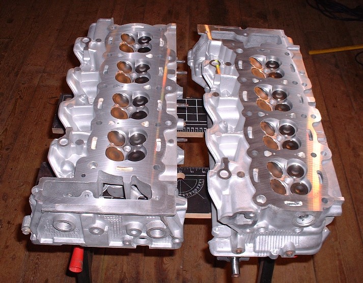
He cleaned the bare heads, bead-blasted them, planed them, re-cut the valve seats, and put in all new intake and exhaust valve guides, new valves, new cam followers, and reconditioned cams for about $1400. Not cheap by any stretch, but not bad for a N*. I think you’ll agree they look like new too. God I love the look of those 32 valves! (insert Tim-the-Toolman grunt here)
A thing of automotive beauty... I'm restraining myself from posting the twenty-something photos I took of just the heads from different angles.
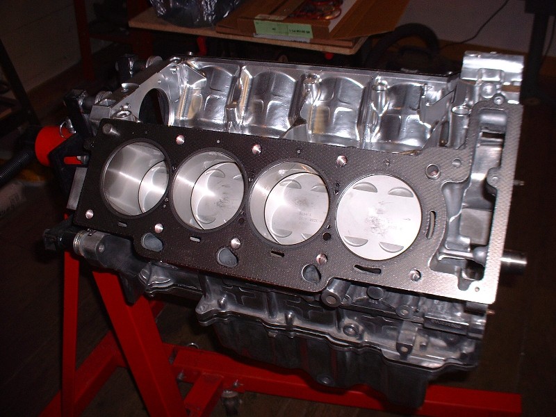
I almost didn’t want to put the heads on the engine and hide all those shiny mechanical parts, but my wife didn’t agree they’d make great coffee table conversation pieces. I kept them tightly wrapped up in clear plastic bags for months showing anyone and everyone who walked through my shop, but the time finally came to install them. Despite all the recommendations from everyone to use cometic gaskets, I bought the Fel-Pro Permadry head gasket set (part number HS26150PT-1) at $250 for the set. I can’t offer any other explanation than cost for my choice. At some point the piggy bank just says “No”. Here they are installed on the deck surfaces just waiting to be sandwiched by the heads.
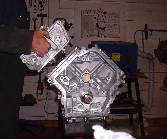
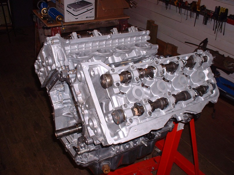
And this is the crowning moment when the first head was finally put in place… Yay! Not surprisingly, the heads are actually quite light and easily handled by one person despite their size.
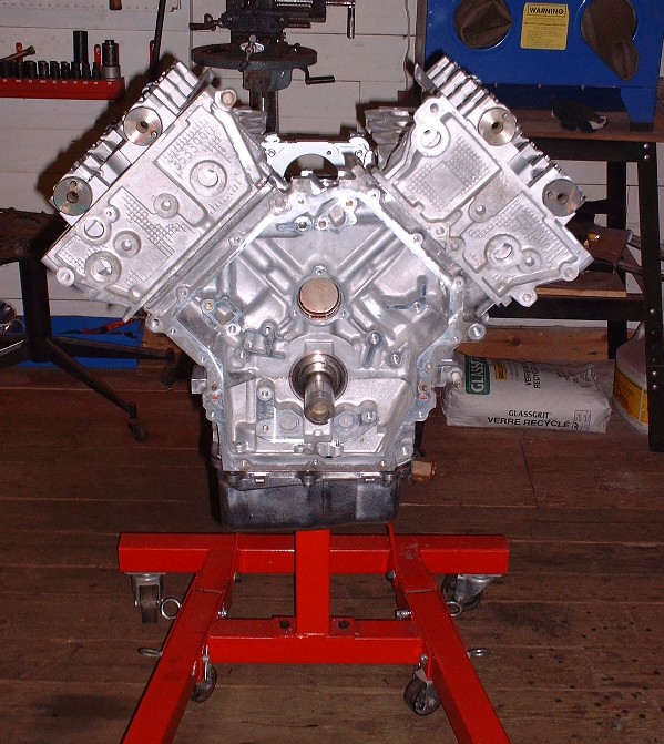
And here’s the double-crown look. From this point of view, without the intake, it’s clear how the double overhead cam heads make the engine so much wider than say, a SBC. I know the Northstars fit in a stock Fiero engine bay, but it’s kind of nice knowing that I’ll have an extra three inches of depth due to the frame stretch on mine.
In my next post I’ll go over torquing the heads down and what to look for to prevent foreign object damage from the by-products of the headbolts.
[This message has been edited by Bloozberry (edited 05-26-2010).]
I'll never be able to afford what you are doing to your engine, but I would like to make an album of all your great pictures and I'm learning a lot from your build. Much appreciation!
With the heads in place, the next step was getting them torqued on. There’s some good discussion here on PFF about whether the head bolts are reusable or not since the GM service manual states that they must be replaced without really explaining why. The consensus is that they are theoretically reusable since they aren’t torqued beyond their yield point (ie TTY). But from a practical standpoint, they should be replaced because of the specialized coating on the threads. Apparently it is a one-time-use coating that cannot be reapplied to the threads outside of having the highly specialized machine processes at your disposal. One other thing to point out here, is that if you haven’t drilled out your OEM threads in the block and replaced them with inserts, GM makes it pretty clear that you MUST clean the coating left over from the old head bolts out of the threads in the block before using new bolts.
So armed with this information, I took my 20 perfectly good used head bolts and set them in my bin of used-big-bolts-in-case-I-ever-need-that-particular-odd-size-ever-again. It’s amazing how many bolts are collecting dust in there. And off to the internet I went to order two boxes of ten Fel Pro head bolts (p/n ES-72186) at $42.50 each box. Here’s what they look like:
Notice there’s not only a coating on the threads, but also on the underside of the head too. Presumably it’s there to give an accurate torque reading, but then again these bolts are tightened with a specific number of degrees of rotation so there’s not much need to reduce the friction under the head. It's possible that it's a sealant to keep engine oil from creeping down the bolt holes and affecting the coating on the threads, but I'm just speculating. One thing it does do is give you a hard time after you’ve finished torquing the bolts. The rubberized orange sealant squeezes out as the underside of the bolt comes in contact with the cylinder head, and then gets pinched off by further tightening. So you end up with these little strands of orange sealant dropping off into the cylinder head. I wasn’t impressed since it took about half an hour using tweezers to pick out the pieces after I was done.
Here’s a quick pic of me using the angle meter again while torquing the head bolts on. For these, you start by applying 22 lbft of torque with a torque wrench to all twenty bolts in a particular sequence and then recheck them a second time. Next you rotate all twenty head bolts in sequence a further 60* one after the other, then go around again for another 60*, and then a final 60*. It takes a bit of time to set up the meter each time and you really don’t want to be in a rush or be disturbed while doing this and lose track of where you are in the sequence. It’s best if you lock yourself in your garage and let no one disturb you until it’s done.
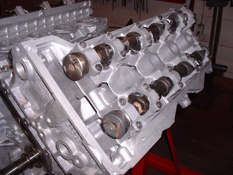
Here’s a topside view of the heads once they were installed. The orangey-yellow stain on the intake cam and the white stain on the exhaust cam are factory paint markings probably to enable the assembly line worker to differentiate between the two at a glance.
And here’s a close up of the cams. Notice that the cam journals ride directly on the casting, without bearings per se. If you’ve been following my thread since the beginning, you’ll remember that I had to replace a number of the cam bearing cap bolts due to them having been over-tightened at some point in their previous lives and therefore significantly stretched beyond their yield point… two of them to the point of fracture. Luckily I was able to steal a couple from my spare-parts engine.
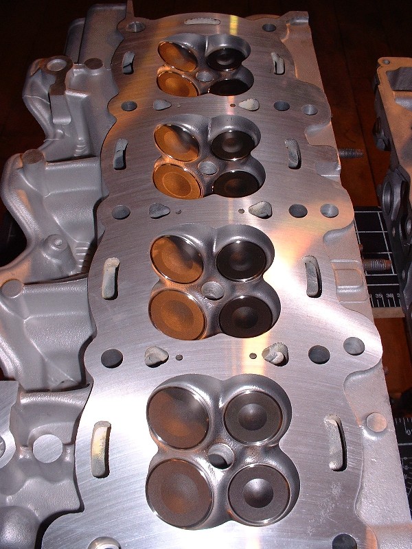
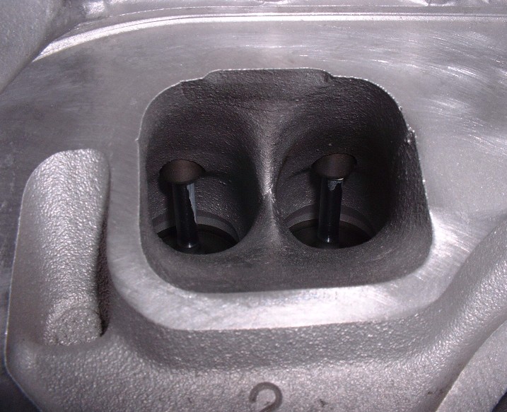
A picture is worth a thousand words, so here’s a close up of one of the intake ports just dying to have something accidentally fall into it. It’s a good idea to mask off the intake decks until you’re ready to install the intake.
Yes Darkhorizon... it's going to be normally aspirated. I figure trying to get this thing to run nicely on either a reprogrammed LS1 or a Caddy PCM is going to be challenging enough!
Yes Darkhorizon... it's going to be normally aspirated. I figure trying to get this thing to run nicely on either a reprogrammed LS1 or a Caddy PCM is going to be challenging enough!
Its not so bad, just pick up a TC2 for about $700 and you will have it dialed in in no time. I considered stepping in behind AJ and finishing where he has sorta faltered at as far as the plug and play northstar market is concerned. I am a bit confused why Ryan at GMtuners has yet to offer anything (although I think he would be your best bet for getting a economical mail-order tune). I just do not have a northstar to play with to justify getting a TC2 (I would probably need 2 northstars to justify doing 1).
Boost on a LS1 pcm is possibly the easiest thing you could do. It is just a matter of getting a maf sensor that mind the boost (pretty much any gm maf will work great, some are better than others)
I bet if you begged HPT enough, they would plug in the northstar bits to their software as well.
Thanks for the info Darkhorizon... I'll be looking at management systems soon enough so this will help.
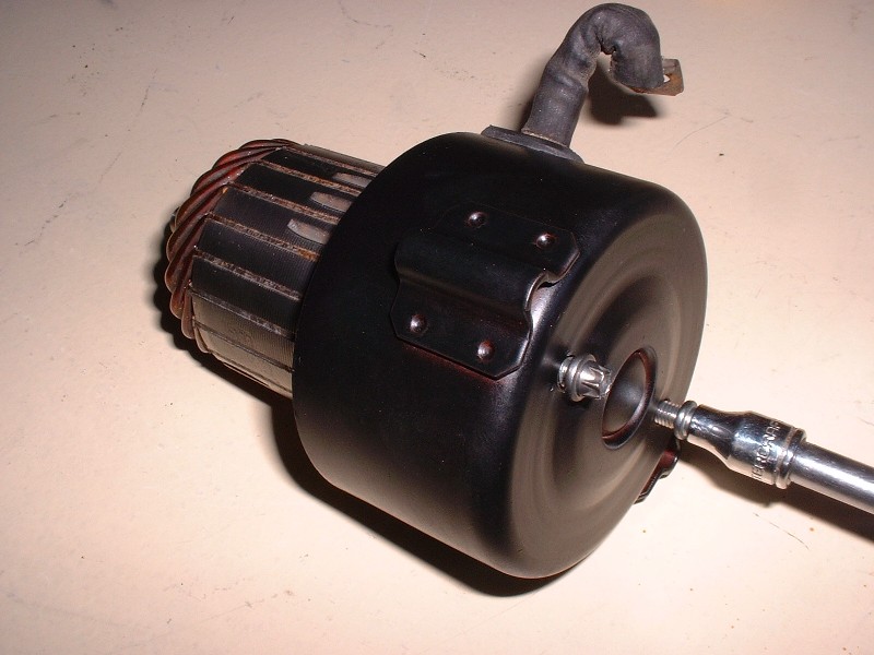
Back to business: At this point, rather than carry on with the installation of the timing chains and sprockets, I decided to take a different tack and rebuild the starter. If any of you aren’t familiar with the Northstar starter, it’s located under the intake manifold in the Vee formed by the cylinders. It’s a crazy location at first glance, but on the other hand it leaves more room on the exterior of the engine block to route things like the exhaust system, axles, and mounts. I kind of like the ingenuity behind the decision to stick it in an otherwise empty space.
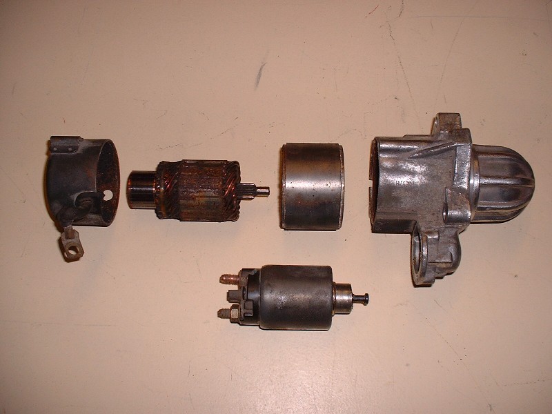
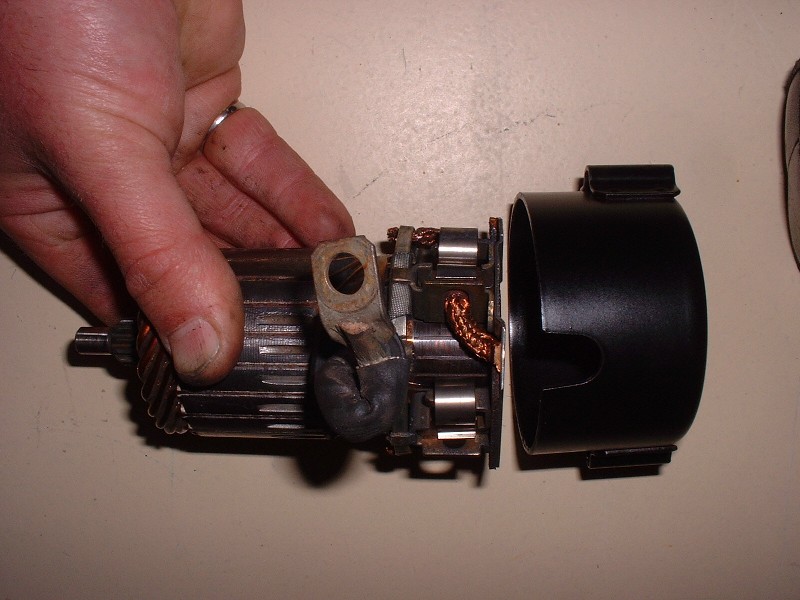
Of course this just means that it would be silly to stick the old one back in without rebuilding it. Mine looked OK from the outside, but it was a different story once I opened it up (another reason not to just install a N* without taking a good hard look at it). Here’s a breakdown of the major parts from top left: brush carrier, armature, magnet housing, gearbox, and at the bottom of the image is the solenoid.
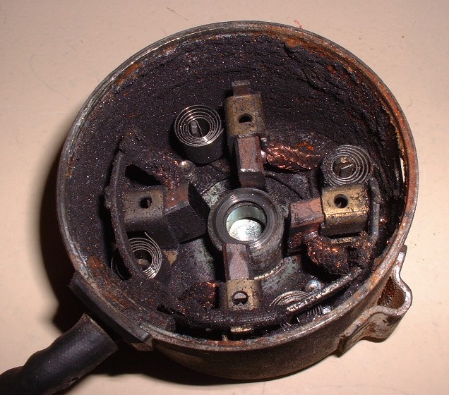
Here’s a close up of the housing for the starter brushes. Note how much dust there is from the wear of the four brushes. I would imagine that at some point in time that all that electrically conductive dust would cause problems. The entire four-brush assembly is held in the housing with only two screws making it easy to take out and clean. Once removed, all I did was spray some electrical component cleaner on the brush assembly and in the housing to rinse it all out.
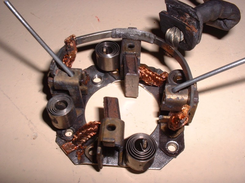
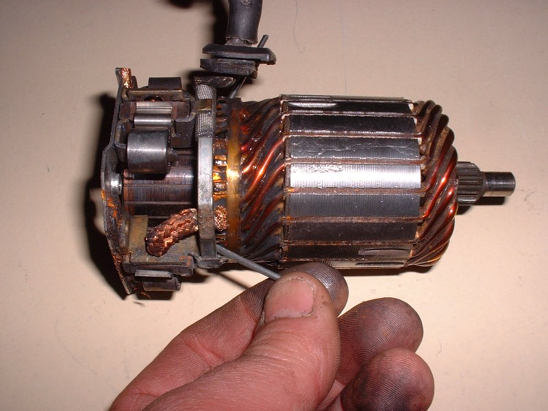
The brushes were nowhere near worn out, so there was no need to replace them. Notice in the picture below that there are holes in the rectangular brush guides that allow you to stick in a small diameter rod to hold the brushes in the retracted position. This allows you to slip the commutator end of the armature back in between the brushes later on.
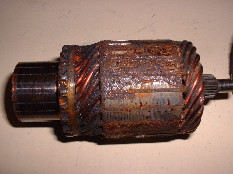
Here’s the commutator/armature assembly before I attacked it with the wire wheel on the bench grinder. (The commutator is the part on the left and the armature is on the right.) Mine had obviously been penetrated by moisture and sat in the same position for some time as the armature had a build-up of rust on one side. If you use a wire wheel to clean one up, you have to be careful not to grind away any of the insulating varnish on the copper wires of the armature coils. There was also a lot of ground-in brush dust between the individual sections of the commutator so I took an Exacto knife and cleaned out the grooves.
Here’s what it looked like after it was cleaned up. Once it was spic and span, I mated the brush assembly to the commutator end of the armature and pulled out the little brush retaining pins I had made out of some piano wire. The brushes snap into place since they’re spring loaded.
With that bit of business taken care of, I could reinstall the guts of the motor assembly back into the freshly refinished brush housing. The brush housing has a small Oilite bushing in the end that the shaft of the armature slips into.
Once the rubber plug for the main wire lead is lined up with the notch in the housing, the brush assembly can be screwed to the housing from the outside. At this point you have to be careful not to turn the assembly upside down since the armature will fall out. If that happens you have to remove the brush assembly again and retract the brushes with the pins and start over again.
[This message has been edited by Bloozberry (edited 06-01-2010).]
Originally posted by Bloozberry: Back to business: At this point, rather than carry on with the installation of the timing chains and sprockets, I decided to take a different tack and rebuild the starter. If any of you aren’t familiar with the Northstar starter, it’s located under the intake manifold in the Vee formed by the cylinders. It’s a crazy location at first glance, but on the other hand it leaves more room on the exterior of the engine block to route things like the exhaust system, axles, and mounts. I kind of like the ingenuity behind the decision to stick it in an otherwise empty space.
With the engine in the car, it takes about 10 minutes to get to the starter. Under normal circumstances, the starter will also be CLEAN. The Northstar has the easiest starter replacement of any engine swapped into a Fiero. Don't even have to lift the car.
With the engine in the car, it takes about 10 minutes to get to the starter. Under normal circumstances, the starter will also be CLEAN. The Northstar has the easiest starter replacement of any engine swapped into a Fiero. Don't even have to lift the car.
Nice thing about the N* starter is you can swap the motor to the later small form factor 60 dgree v6 starters and vice versa ..since I have tons of them I am good to go for the forseeable future
Nice thing about the N* starter is you can swap the motor to the later small form factor 60 dgree v6 starters and vice versa ..since I have tons of them I am good to go for the forseeable future
Not unless you change the drive housing... The Northstar starter is mounted via axial bolts, while the V6 starter is mounted via perpendicular bolts.
Edit: N/M, you meant swap the Northstar drive housing onto the V6 starter.
[This message has been edited by Will (edited 06-02-2010).]


 I'll address your comments one at a time: