I got the engine/cradle assembly back under the car and started lowering it down to find just exactly where the trunk wall interference was going to be. I stopped lowering when the car was still about 6 inches too high to mate with the cradle when I took the photo below. I took it through the hole where the driver's side strut tower used to be, looking inwards towards the passenger side of the engine bay:
You'll have to use your imagination to see that the lower portion of the timing gear bump on the far side of the valve cover would contact the step in the trunk wall before the car was fully lowered onto the cradle. The other thing I noticed is that the stock Caddy rear exhaust header would also hit the trunk wall before the cradle was fully in place. I had always assumed I would be able to make the stock exhaust system work until now... clearly with the height and angle of the collector there would be no room to snake an exhaust system in the space that's still available:
Not wanting to remove any more of the trunk wall than necessary at this stage, I started with a cut to provide the needed clearance for the timing gear bubble:
That allowed me to better judge how much more of the trunk wall needed to be removed to clear the rest of the valve cover, allowing for engine movement under load. So I measured and marked it up, then covered my engine with remnants of an old Evolution 3 car cover to protect it from the hot bitties flying off my cut-off wheel (note to self: Evolution 3 car covers are NOT hot-bitty-resistant.)
With the piece removed, the need for the cut-out becomes a bit more obvious.
Crossing my fingers, I started lowering the car further, only to notice one more problem area... and though it looks little, it's a biggie. Here's my drawing from earlier showing where the new interference area is (red arrows).
I'm still mulling over how I going to solve this one since it appears I either need to move the engine further forward on the cradle, or further to the left, or more likely a combination of the two. Either way it's yet another problem arising from not having drawn out the passenger side earlier on.
Today I spent some time trying to figure out how to get myself out of my current jam: I can't install the cradle into the car because the engine interferes with the lower passenger side frame rail. To figure out by how much I needed to shift the engine on the cradle I first rolled the cradle around focussing on getting the engine/trans sitting exactly where I wanted it in the engine bay, without any regard for where the cradle was with respect to the frame mounts. Once I found the sweet spot, I would be able to measure how far off the cradle mounts were from lining up with the frame mounts. Those measurements would then indicate by how much the engine needed to shift on the cradle.
To get the needed clearance I rolled the cradle forward and to the left until I ended up with what I thought would be the minimum clearance needed. The further forward I moved the engine, the greater clearance width-wise I had given that the lower frame rails diverge towards the front of the car. The trade off though is that the further forward I push the engine, the more my axles would need to angle backwards. I settled on moving the engine 25 mm further forward, and 20 mm further to the left within the engine bay. Here's the top view showing how close the valve cover comes to the lower frame rail with the engine placed where I wanted it:
Bear in mind that the engine sits much higher up so once the valve cover get's past the lower frame rail, there's an additional 5 mm or so between the rail and the engine block. At the transmission end of things, there isn't much more room between the end of the transmission housing and the driver's side lower frame rail:
I discovered that just saying I'm going to move the engine further forward and to the left on the cradle doesn't mean there's actually room on the cradle to do so. After I had the cradle back out I realized that I only just barely had enough room to do what I wanted. Moving the engine forward 25 mm means that the forward cradle cross member will need to be notched slightly to make room for the oil filter. I'll need to leave some room to allow for engine to rock under load:
And then I discovered that shifting the engine/trans to the left on the cradle by 20 mm wasn't going to be without complications either:
Here's the same area from another angle:
As you can see, there's only 19 mm between the cradle side rail and the unused mounting boss on the transmission end. Luckily, that boss can be shaved down without any impact. I think that will solve the final fitment issues... then I'll have to update my drawings
This is going to be my last post for a week or so as I head out West to pick up some pieces that will hopefully represent a major development in both my and Yarmouth Fiero's projects... all made possible through the generosity of a selfless British Columbian Fiero-nut who has a heart of gold. More when I return!
Just out of curiosity, why no a remote oil filter? Might solve some of the spacing issues and you can place it where you don't even have to lean over to pull and replace it!
I'll post a few pictures of Yarmouth Fiero's and my latest acquisition shortly, but to answer a few quick questions:
Johnyrottin: I could use a remote filter I suppose, but I was looking at staying cheap if possible.
Will: Other than moving it back 3" due to the frame stretch, I kept the axle center line in the same relative location as stock. Then I placed the F40 where necessary to meet up with the axle line, then I attached the engine to the transmission.
I believe two things contribute to my engine being further back in relation to the trunk wall than your installation:
a. you're using a Getrag if I'm not mistaken, and I believe the F40 may not have the same relative distance between the input and the output shaft which changes the location of the engine relative to the axle and therefore in the engine bay; and
b. I'm using CHRFAB's double bump valve covers which are wider than the stock Caddy covers.
Regardless, now that I have to move my engine a further 25 mm forward on the cradle to account for other clearance issues, I may not have a problem with the rear trunk wall after all. No biggie.
It may sound silly or uneducated, but just why are you running in to so many fitment issues? I know there are several N* installed in Fieros, so I'm just wondering what you are doing ao differently to cause these issues. Is it your custom cradle and suspension set up that is the root of the issues?
It's not the suspension, it's the fact that I'm using:
a. an '88 Fiero (with the narrower distance between the tops of the strut towers than the earlier cars);
b. I'm using the wider aftermarket CHRFAB "double bump" valve covers. (The only other person that's used these covers on an '88 N* combination had to chop off part of the valve cover whereas I chose to cut off the towers instead since I don't need them);
c. I've raised the cradle by one inch thereby raising the engine relative to the rest of the car; and
d. I believe I'm the only person to mate an F40 to a Northstar in any Fiero, and if not, then I'm likely the first to install the combination into an '88 chassis. Either way, that forces me to locate the engine/trans in the engine bay differently than those before me.
[This message has been edited by Bloozberry (edited 07-14-2013).]
c. I believe I'm the only person to mate an F40 to a Northstar in any Fiero, and if not, then I'm likely the first to install the combination into an '88 chassis. Either way, that forces me to locate the engine/trans in the engine bay differently than those before me.
The big difference is his install/engine placement was first dictated by the getrag 5 speed, then he later converted it to the F40 and left the engine where it was. Focusing on keeping the F40 differential in line with the wheel center was one of the key differences with your swap. Most just allow the test fit to dictate where the drivetrain will be placed and live with whatever axle angle they end up with.
Yes, of course, how could I have forgotten Zac's build. Two differences between mine & his are the valve covers taking more room in mine, and the fact that I've raised the cradle by an inch.
[This message has been edited by Bloozberry (edited 07-14-2013).]
I can't get excited about CV joint angle with diff centerline +/- 1" from stock, and would barely even think about +/- 2". Heck, GM transmissions in the same body had about 1" of variation across the spectrum.
It's not the suspension, it's the fact that I'm using:
a. an '88 Fiero (with the narrower distance between the tops of the strut towers than the earlier cars);
b. I'm using the wider aftermarket CHRFAB "double bump" valve covers. (The only other person that's used these covers on an '88 N* combination had to chop off part of the valve cover whereas I chose to cut off the towers instead since I don't need them);
c. I've raised the cradle by one inch thereby raising the engine relative to the rest of the car; and
d. I believe I'm the only person to mate an F40 to a Northstar in any Fiero, and if not, then I'm likely the first to install the combination into an '88 chassis. Either way, that forces me to locate the engine/trans in the engine bay differently than those before me.
Gotcha. So you are in uncharted waters with a lot of this build.
From what I have been able to gather, the valve covers are the biggest problem. What is the reasoning behind using them? Looks? (again, sorry if this has been covered)
Yep... for looks. The Caddy aft valve cover is ugly in my opinion. Since it is hidden in the Cadillac models, no effort was made by GM to make it pretty like front valve cover, and they're not interchangeable. The problem is that when installed in a Fiero, the ugly aft one becomes the one that's seen the most.
...and I thought the torque strut mount was tough. Holy cow... anyone that tells you removing the old hinge boxes is easy, is either being sarcastic or doesn't know what the hell they're talking about. I can't believe how long I struggled to get those damned things off. Whoever designed the program that spot welded them in clearly wasn't thinking down the road about us tinkerers, because the welds holding them to the bottom of the rear window sill aren't accessible with a drill, grinder, cut-off wheel, or any other tool known to man. I finally got them off but it's a good thing I don't have a swear-jar in the shop. It's also a good thing that I'm replacing the lower half of the rear window sill with some rectangular steel tubing like Yarmouth Fiero did in his build thread. Mine now looks more like a piece of Swiss cheese that someone took a chainsaw to!
Here's the rest of the hardware I removed from the firewall:
Do you still have the hinge boxes? Mind sending me your right hand one?
I removed more material from mine than I should have, and I'd like to replace it. Starting with yours will save me from having to remove the one from the parts car. When first doing the swap, I didn't know how high the engine would end up sitting, so I cut away more than I should have. I don't have either of the two original hinge mounting studs anymore... Now I have to shim my modified hinge to get the decklid into the right location. I'd like to have the original adjustments back.
Now that I know where the engine goes, I see that I could keep the upper hinge mount stud on the right side, which would preserve all of the original adjustment features.
You can have it for the cost of shipping. I can measure it, weigh it, and then see how much it would cost to send it but you'll need to PM me your mailing address so I can get a few estimates.
I was very happy last night when I finally got the cradle installed all the way up into the frame of the car. It was a long journey to get to the same point I was at last month before I found out I had miscalculated the position of the engine on the cradle. I hummed and hawed at several different methods to fix the problem since none of them were going to be particularly easy to execute. I figured I had three options to shift the engine on the cradle 20 mm's to the left and 25 mm forward. I could either:
a. leave the cradle "as-is" and modify the brackets between the cradle and the engine/trans. (I opted out of this route for a number of reasons including the complexity of all three brackets, and the need to notch the front cradle cross member for the oil filter)
b. leave the brackets "as-is" and lengthen and relocate the engine/trans mounting bosses welded to the cradle. (Not a great option either since this would place greater bending loads on the longer bosses, and still require the need to notch the front cradle cross member for the oil filter). It would also have placed one of the bolts of the rubber engine mount directly in line with the wall of the tubing that makes up the front cradle cross member; or
c. leave the brackets "as-is" and relocate the entire front and rear cross members further forward on the cradle side rails, then shift the engine/trans mounting bosses (welded to the rear cross member) over to the left.
Option C is what I ended up doing even though it was fairly involved. I had to outright replace the old front and rear cradle cross members since once cut off, they were too short by two times the width of my cutting wheel. Then I had to set up a jig to re-weld the side rails and new fore and aft cross members back together. And finally I had to cut, bend, and weld new bosses on the aft cradle cross members since the old ones no longer fit properly, as well as drill new mounting holes in the new front cross member for the forward engine mount. In other words, I had to replace everything about the cradle except the two side rails. I'll update the cradle drawings I posted (several pages back) a little later this week to reflect the changes in case anyone uses my plans in the future.
Shifting the engine/trans forward on the cradle this way prevented me from having to notch the front cross member for the oil filter (or buying a remote filter system). However there was still the side-to-side issue where one of the (unused) mounting bosses cast on the transmission housing was going to interfere with the LH cradle side rail as mentioned several posts ago. Since it wasn't needed, I simply used a cut-off wheel on my angle grinder and sliced several sections off...
...until I got the clearance I was looking for:
With the cradle and transmission mods out of the way, I was ready to try stuffing it into the engine bay again (with fingers and toes crossed). Just getting the whole assembly onto wheel skates is an adventure in itself... I can't simply lower it onto the skates using the engine hoist because the legs of the hoist stand taller than the skates. With the crane, I've got to lower the whole assembly onto a set of blocks high enough to pull the crane legs out from under the cradle, then roll the skates under the cradle, then use a pair of low clearance floor jacks to raise the cradle off the blocks and finally lower it onto the skates. Whew! No wonder it takes so much time to get anything done!
This time everything slipped into place like it was coated in butter, but the engine bay could not have been made any smaller otherwise it would not have fit. There are four areas to keep an eye out for tight clearances. I'll showcase each trouble area with a photo and brief description starting with:
a. Aft valve cover and camshaft sensor to passenger main lower frame rail.
Here's a photo that shows the side clearance between the aft valve cover and the camshaft sensor to the lower passenger side main frame rail of the car... looking down from where the strut tower used to be:
There's only about 5 mm between the camshaft position sensor and the lower frame rail while the car is being lowered onto the cradle. The engine can't be shoved any further towards the driver's side because there is an equally small amount of clearance between the F40 transmission and the driver's side lower main frame rail. Once the sensor and valve cover passes the rail, there's more clearance since they sit well above the frame rail as shown here:
b. Aft valve cover to trunk wall.
The clearance between the aft valve cover and the trunk wall also changes as the cradle is installed. I first connected the two front cradle mounts to the car frame then pivoted the rear of the cradle up into position. I couldn't have done it this way without having trimmed the trunk wall as I did earlier on since the engine swings on a wide arc and would have interfered with the wall. Once fully installed, there's enough clearance between the valve cover and the trunk wall but not an overly large amount as seen here:
c. Transmission to driver's main lower frame rail.
As mentioned earlier, the F40 transmission comes within about 10 mm's of the driver's side main lower frame rail as the car is lowered onto the cradle. (One of the nice things about this design is that there are no need for lower frame rail notches.) The closest it comes is where the aft cast "fin" or gusset narrowly misses the rail where it tapers the most:
Any misalignment of the cradle to the car as the car is being lowered decreases that gap in a hurry and risks hanging up on the transmission or the valve cover.
Here's the side view showing what portions of the transmission are in line with the lower frame rail once the cradle is fully installed. (If you look carefully, you'll see a vertical silver line on the frame rail with a barely legible "C/L" scribbled beside it... that's where the transmission output shaft used to line up before moving the engine/trans forward 25 mm's. The wheel location hasn't changed so the axle will have to slant backwards from the transmission to the wheel to accommodate the change):
d. Forward valve cover and passenger deck lid hinge box.
In my particular project, there's bags of room between the forward valve cover and the cabin firewall given the 3" wheelbase stretch. Even more so since I've removed my deck lid hinge boxes for a different design.
This isn't the case with non-stretched cars though, so anyone considering my 25 mm raised cradle design on a non-stretched chassis should be aware that the passenger hinge box will almost certainly contact the top of the forward valve cover before the cradle is fully in place. One other thing to keep in mind as well is that I've removed my strut towers to accommodate my new rear suspension design, but they would have been in the way of the aft valve cover regardless.
The only concern I would have is how much strength are you giving up by cutting away the strut towers? I notched mine but filled it in with a 1/8" Steel plate to help reinforce the area to hopefully the original strength or better.
I really like how the engine looks in your engine bay, I cant wait to see the finished product.
If I were to leave the gaping holes wide open where the strut towers once were, the frame strength would be somewhat compromised since there isn't much material triangulating the upper and lower frame rails anymore. I do plan to stiffen the area again using sheet metal to block off the holes and firm up the connection between the upper and lower rails, though the entire area will see a substantial reduction in vertical loads since the spring forces will be redirected fore and aft to a new structure just aft of the cabin.
I'll also have a third, mid-level frame rail installed running fore and aft between the cabin firewall and the strut tower cross brace (the one integral to the trunk wall) in order to mount the spring and push rod bell crank. This third rail should stiffen the rear frame in bending somewhat especially if I notch the upper frame rail to clear my tires at full jounce.
I know you said you were trying to keep the axles straight, but pretty much every other Northstar swap has kept the crankshaft centerline in the same place as stock... Obviously that's easy with a 282 or other stock transmission... more difficult with the F40. As you've noted, the clearances are extremely tight and the engine doesn't have to be very far out of position to screw things up. My "dance" to R&R my powertrain is amusing. I use an overhead chain hoist on an I-beam, and I have a three-point chain setup with the chains set to the right lengths to hold the powertrain level. From there it's up an inch, left an inch, up an inch, forward an inch, up an inch, right an inch, etc... just to keep the projections from the cradle from snagging fuel lines and A/C hoses and all the other things that are in my engine bay that aren't in yours right now. If GM had built Northstar Fieros, the cams to guide the motion of the powertrain assembly as it was installed in the body would be a sight to behold.
I don't know if I could have saved you a bunch of work if I'd watched this thread more closely or not.
Thanks for your insight Will. I laughed at the "dance" analogy.
This is just a quick post to advise anyone that's interested, that I've updated the basic cradle drawings on page 16, about halfway down the page, to reflect the new locations of the front and rear cradle cross members. I've also updated the drawings of the engine mount locations (and their effect on the engine and transmission locations) shown in the drawings on page 17, about 2/3rds of the way down.
(Edit: I should add that these changes don't affect any of the new rear suspension characteristics or dimensions posted earlier)
[This message has been edited by Bloozberry (edited 07-26-2013).]
I can't get excited about CV joint angle with diff centerline +/- 1" from stock, and would barely even think about +/- 2".
When Porsche extended the wheelbase of all 911 models by 57 mm (2 1/4 in) in 1969, they left the engine and transmission where they were and simply moved the wheel hubs back and accepted the resulting axle misalignment angles. FWIW, this arrangement was trouble free over the 15 years and 125,000 miles I owned my '69 911S.
[This message has been edited by Marvin McInnis (edited 07-27-2013).]
Funny you should say. I spent an hour or so searching the internet yesterday for an image I saw a couple months ago depicting the top view of an AWD Porsche (couldn't remember what model) that had its fore and rear axles canted backwards by 15 or so degrees. Couldn't find the pic though. Regardless, I've read that most modern CV joints can handle up to 23 degrees so I wasn't especially worried about my configuration... although around here (where annual mechanical inspections are the norm) I try to avoid anything that might attract concern from the "know-it-all" mechanics.
I ordered the majority of the parts to build the rear suspension today. These are the parts I ordered from Summit Racing:
Shocks: QA1 Proma Star coil overs with 18 position external single adjustability P/N: HAL-DS501 qty 2 Rod ends (LH thread): QA1 3 piece PTFE lined 5/8"-18 male with 1/2" head bore, 31,390 lb load capacity, 10 deg misalign P/N: HML8-10T qty 10 Rod ends (RH thread): QA1 3 piece PTFE lined 5/8"-18 male with 1/2" head bore, 31,390 lb load capacity, 10 deg misalign P/N: HMR8-10T qty 10 Upper aft links: AFCO 5" X 5/8" swaged tube P/N 36175 qty 2 Upper fwd links: AFCO 7" X 5/8" swaged tube P/N 36177 qty 2 Lower links: AFCO 8" X 5/8" swaged tube P/N 36178 qty 4 Push rod links: AFCO 5" X 5/8" swaged tube P/N 36175 qty 2 Jam nuts RH thread (5 per package): QA1 5/8"-18 P/N JNR10S-1-5PK-QA1 qty 2 Jam nuts LH thread (5 per package): QA1 5/8"-18 P/N JNL10S-1-5PK-QA1 qty 2
And from Jegs:
Rod end spacers: 1/2" ID X 1/2" long P/N 555-64201 qty 20 (2 per package)
All of the rod ends and a couple of the swaged tubes were back-ordered so it may take a while for everything to get here. In the meantime, I've got to get cracking on removing the fiberglass body panels from my frame in order to properly prep the underlying metal and make some needed elbow room for the mods to the frame to accept the new suspension. More soon.
(edit: corrected wrong part numbers for rod ends and changed swaged tube lengths to accommodate jam nuts)
[This message has been edited by Bloozberry (edited 09-21-2013).]
Over the past couple days I've been chipping away at removing the F355 door panels and the rear quarters. The door skins had to come off because the IFG door panels are made with the rocker panels integrally moulded to the door bottoms, unlike the real F355. When the door is closed, it doesn't show that much to the untrained eye, but it looks very strange indeed when the door is opened since you expect to be greeted by a nice wide door sill, except there is none! That has to change for me to be happy, so off came the door panels. I don't know what the previous owner used to bond them onto the metal of the door, but it wasn't a walk in the park to get them off.
Next came the rear quarters including the rear valence panel and bumper cover. IFG moulded all of these parts together as one big piece so there aren't any parting lines where you'd expect to see them. There are many other problems with the original rear quarter panel including wheel arches that are too high, crooked belt lines, crooked rear bumper cover lines, and improperly formed door jambs to name a few. Luckily for myself and Yarmouth Fiero, 355Fiero out in Victoria BC already did much of this work on his panels, which he recently and very generously donated to help advance our projects. I also plan to replace the rear valence panel (the part with the tail lights) with a wire mesh version a-la F355 Challenge, install a new cross member under the rear window to tie in the new shocks, dog bones, and deck lid hinges, and finally install a rear bumper bar where there was none(!). Bottom line: the quarters had to come off.
The previous owner used fibreglass resin and Bondo to "glue" the door jamb portion of the rear quarters to the space frame. I was surprised at how tough that was to take apart. I ended up using a hammer and chisel to pry the area around the jambs away from the frame to break the bond. The only other place the rear quarters were held on was to the base of the sail panels. Again, the PO used Bondo to glue the sails to the quarters so separating them meant using a cut-off wheel on the angle grinder:
It was a bit tricky to get the cutting wheel to follow the joint, but overall it went pretty well. I wasn't too concerned about nicking my old quarters since I'll be replacing them with 355Fiero's quarters. (Regardless, all of these panels will only serve as bucks for new moulds that Yarmouth Fiero and I are planning). Once the base of the sail panels were sliced, the rear quarters simply slid off the rear of the frame with a little tugging and a little jiggling:
With that out of the way, I now have lots of room to start cleaning up the frame, building the mounts for the rear suspension, and planning the mid-mounted radiators:
Here's another view:
Edit: spelling)
[This message has been edited by Bloozberry (edited 08-06-2013).]
Great job Blooz. Sometimes you just gotta fire up the cutting tools and go at it. I'm sure it's like a breath of fresh air ( except for the dust) to finally get that rear body work off. Were there any suprises found once you had it pulled back? Maybe rolls of $100 bills stuffed in the frame rails?
Funny you should say. I spent an hour or so searching the internet yesterday for an image I saw a couple months ago depicting the top view of an AWD Porsche (couldn't remember what model) that had its fore and rear axles canted backwards by 15 or so degrees. Couldn't find the pic though. Regardless, I've read that most modern CV joints can handle up to 23 degrees so I wasn't especially worried about my configuration... although around here (where annual mechanical inspections are the norm) I try to avoid anything that might attract concern from the "know-it-all" mechanics.
I'm currently running a (L)7deg / (R)11deg offset on mine with the Chrysler swap, I have about 1500 miles on so far and the only issue I've had is a shudder on hard acceleration. I think it may be from the tripod end of things but I haven't dug into it any deeper as of yet. From some of what I've read, tripod joints don't like as much angle as the 6 ball C/V's and this may be why I get the shudder. IIRC Porsche uses C/V's on both inner and outer which may be why they haven't had problems.
[This message has been edited by seajai (edited 08-06-2013).]
Originally posted by Will: Engine bay looks big enough to take the real thing...
Wouldn't that be sweet! Now if I could only find that wad of money...
quote
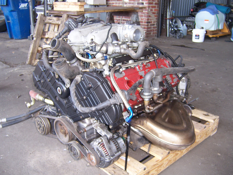
Originally posted by Will: Also, is that another Northstar with the yellow balancer pulley in the background?
Yes it's a spare engine I bought for parts but am now looking at saving it for my '29 Model A hot rod. I had bought a 427 BBC a long time ago but decided it's just too heavy.
Very cool. So many questions come to mind though! What are you planning to use the engine in? Do you have the controller (ECM) and wire harness? What happened to the rest of the car and do you know whether the engine and trans are any good? Can you even get shop manuals for Ferrari engines? Have you priced out any of the parts you're missing? On the one hand my mind is drooling, on the other it's spinning. I have a friend who has a Ferrari 308 that he just got it back from Montreal (nearest authorized shop... 800 miles away) to have the timing chains and the suspension bushings replaced. It cost him $25K including shipping, labour, and parts. I think if I bought an engine and trans like yours I'd only be able to afford to detail it and set it on a pedestal in my shop as a conversation piece! Nice find though.
As for the N* hot rod, I haven't planned that far, but I do see your point about plumbing the water pump. I still have a couple years to think about it.
-This is the 3.4 litre and 5 speed gearbox from a '92 348 TS. 300 HP, 7700 RPM, dry sump. The transmission has pressurized lubrication. -The planned recipient is a 1978 308GTS. I bought it without an engine (Otherwise complete! includes axles), so the match is perfect. -It uses two Motronic 2.5 ECM's. I don't have them, but the boxes themselves are not hard to come by... just the Ferrari chips. The ECM's are completely independent; they even have their own crank sensors. I could power one down while driving and the engine would still run as a 4 cylinder. -It has the complete engine wiring harness. I'll have to build the vehicle side wiring to make it work -I bought a pair of coil packs for $30 from a guy in Latvia on eBay. They're rare here in the US, but apparently used on half the Fiats in Europe. -I will need MAF sensors and a starter... I'm still scratching my head about that. I'll keep watching eBay. - www.ferraridatabase.com has .pdf's of the workshop manuals - Ricambi America and a few other places can get Ferrari parts at almost reasonable prices (Obviously never going to be Chevy cheap...), which means that the cars are much more attainable if you do your own work. -I'll probably convert to spherical bearings in lieu of Ferrari suspension bushings. -I'll need to custom fab oil coolers, dry sump tank, exhaust, EFI fuel system and the usual set of engine swap related plumbing and fitment concerns.
Due to the number of 360's Ferrari built, and the number that end up with upgrade wheels and brakes, 360 wheels and brakes are not unreasonable at all on eBay, and really make 308's look sharp.
[This message has been edited by Will (edited 08-08-2013).]
That should be a really challenging project Will. You'll need to start a thread in the "Other Cars" section as I'm sure there will be a lot of interest. One of the challenges I'm sure you've already considered is how you're going to mount the longitudinal 348 engine into the 308's engine bay designed for a transverse engine. I'll subscribe if you start a thread.
As for an update on my project, I got a couple parcels in the mail today, one marked Jegs and the other Summit. My excitement was short lived though. The Jegs box contained all 20 pairs of spherical rod end spacers as ordered, but the Summit box only had half of the order right. I got the QA1 shocks, all the swaged tubes, and the jam nuts but all 20 rod ends were the wrong parts. At first I doubted myself and thought I may have made an mistake on the order sheet since the part numbers on the packages were indeed what I ordered, but instead of being rod ends, they were tie rod ends. I re-checked the website and still couldn't understand why I got tie rod ends because the photo and the specs did not match what I got. I called the customer service dept and after a bit of research they admitted that the website was clearly wrong, so they are going to make things right by paying for the whole return and exchange process. It's still very frustrating since they won't act until they get the tie rods back in their hands, at which point they will order the correct rod ends (which will be back-ordered since they don't have any in stock). The whole process will put me behind by a month or so. For anyone thinking of using the same parts as me, I've updated my previous post with the correct part numbers for the rod ends.
Anyways, here are a couple photos of the parts that were the right ones... here's everything:
Here are the all the parts that came with the QA1 Proma Star shocks (less the springs, of course). They have 1/2" spherical rod ends at either end, and have a 5.375" total compression range from 11.625" to 17". They have adjustable rebound valving with an 18 position external knob, and they accept 2.5" ID X 12" long springs which happen to be the size I initially bought and installed on my struts before I decided to use an SLA set-up, so I saved a little money there.
And here's a close-up of what one looks like when it's built up. I think they'll look pretty good peeking out longitudinally under the sail panels, framing both ends of the engine/transmission. I should have probably bought the special wrench.
[This message has been edited by Bloozberry (edited 08-14-2013).]


 More when I return!


 It's also a good thing that I'm replacing the lower half of the rear window sill with some rectangular steel tubing like Yarmouth Fiero did in his build thread. Mine now looks more like a piece of Swiss cheese that someone took a chainsaw to!


 I got the QA1 shocks, all the swaged tubes, and the jam nuts but all 20 rod ends were the wrong parts. At first I doubted myself and thought I may have made an mistake on the order sheet since the part numbers on the packages were indeed what I ordered, but instead of being rod ends, they were tie rod ends. I re-checked the website and still couldn't understand why I got tie rod ends because the photo and the specs did not match what I got. I called the customer service dept and after a bit of research they admitted that the website was clearly wrong, so they are going to make things right by paying for the whole return and exchange process. It's still very frustrating since they won't act until they get the tie rods back in their hands, at which point they will order the correct rod ends (which will be back-ordered since they don't have any in stock). The whole process will put me behind by a month or so. For anyone thinking of using the same parts as me, I've updated my previous post with the correct part numbers for the rod ends.


