Pennock's Fiero Forum
  The Construction Zone
  Aurora 4.0l / Izuzu 5 speed swap into 88 coupe (Page 5)

Post New Topic  Post A Reply
Email This Page to Someone! | Printable Version

This topic is 26 pages long:  1   2   3   4   5   6   7   8   9   10   11   12   13   14   15   16   17   18   19   20   21   22   23   24   25   26 
Previous Page | Next Page
next newest topic | next oldest topic
Aurora 4.0l / Izuzu 5 speed swap into 88 coupe by cptsnoopy
Started on: 04-27-2004 07:21 PM
Replies: 1012 (72865 views)
Last post by: cptsnoopy on 11-05-2023 09:50 PM
ryan.hess
Member
Posts: 20784
From: Orlando, FL
Registered: Dec 2002


Feedback score: (1)
Leave feedback


Total ratings: 319
Rate this member

Report this Post12-29-2004 01:05 AM Click Here to See the Profile for ryan.hessSend a Private Message to ryan.hessEdit/Delete MessageReply w/QuoteDirect Link to This Post
 
quote
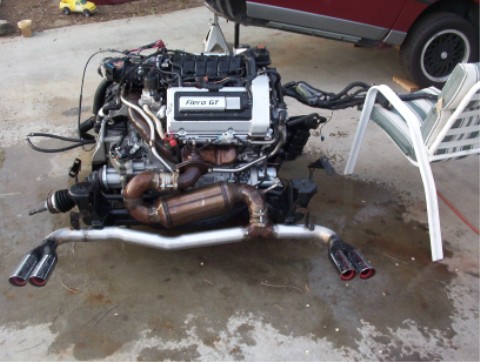
Originally posted by cptsnoopy:
Here is what I was working on when things got hot...

Hmm... why are you cutting your strut towers now?

Also, something to consider..... Right where you have the crossover underneath the oil pan... there used to be a brace between the bottom of the oil pan, and the auto trans. IMHO, it's a very integral part of the structure that keeps the engine and transmission from flexing. (Why else would they make it out of 1/8" steel?)

IP: Logged
GSXRBOBBY
Member
Posts: 3122
From: Southern Indiana USA
Registered: Aug 2003


Feedback score: N/A
Leave feedback


Total ratings: 105
Rate this member

Report this Post12-29-2004 01:49 AM Click Here to See the Profile for GSXRBOBBYClick Here to visit GSXRBOBBY's HomePageSend a Private Message to GSXRBOBBYEdit/Delete MessageReply w/QuoteDirect Link to This Post
He has an 88, he needs the room.

------------------
Bobby from NW Indiana
93 Northstar and 5 speed Getrag
219customs@verizon.net
My build thread

IP: Logged
ryan.hess
Member
Posts: 20784
From: Orlando, FL
Registered: Dec 2002


Feedback score: (1)
Leave feedback


Total ratings: 319
Rate this member

Report this Post12-29-2004 02:24 AM Click Here to See the Profile for ryan.hessSend a Private Message to ryan.hessEdit/Delete MessageReply w/QuoteDirect Link to This Post
 
quote
Originally posted by GSXRBOBBY:

He has an 88, he needs the room.

Ahh... wasn't aware you had to do that.

IP: Logged
cptsnoopy
Member
Posts: 2585
From: phoenix, AZ, USA
Registered: Jul 2003


Feedback score:    (8)
Leave feedback


Total ratings: 60
Rate this member

Report this Post12-29-2004 03:18 AM Click Here to See the Profile for cptsnoopySend a Private Message to cptsnoopyEdit/Delete MessageReply w/QuoteDirect Link to This Post
 
quote
Originally posted by ryan.hess:


Hmm... why are you cutting your strut towers now?

Also, something to consider..... Right where you have the crossover underneath the oil pan... there used to be a brace between the bottom of the oil pan, and the auto trans. IMHO, it's a very integral part of the structure that keeps the engine and transmission from flexing. (Why else would they make it out of 1/8" steel?)

I could have moved the trans to the left a about 1/2" to 3/4" of an inch and maybe I would have had enough room. I felt it would be easier to cut the strut tower and use coilover shocks than to risk the problems of needing different length half shafts. I cut into the strut tower earlier this year in May. I am just now getting to the task of finishing it. I still need to finish the passenger side decklid hinge support then most of the spaceframe work will be done. I squished the exhaust going under the pan in hopes of being able to use an engine to trans support there. I can't see how it will support the trans from flexing very well since it will be alot longer than the original support for the 4T80 but it won't hurt to make one up anyway. I'll use either 1/8" or 1/4" steel but no thinner than that.

IP: Logged
Rickady88GT
Member
Posts: 10648
From: Central CA
Registered: Dec 2002


Feedback score: N/A
Leave feedback


Total ratings: 202
Rate this member

Report this Post12-29-2004 02:15 PM Click Here to See the Profile for Rickady88GTSend a Private Message to Rickady88GTEdit/Delete MessageReply w/QuoteDirect Link to This Post
I got the tank for about $10 used.
I used two 90* sections of 2.5 of exhaust doghnuts for the duel exhaust system. The sections are trimed and welded back to back to form a smooth flowing "T" but it is more like a "Y" than a T. The inlet to the "Y" is 3" the two out lets are 2.5.

It is kina hard to see but it is not a "T" I never got any close ups of it.

[This message has been edited by Rickady88GT (edited 12-29-2004).]

IP: Logged
cptsnoopy
Member
Posts: 2585
From: phoenix, AZ, USA
Registered: Jul 2003


Feedback score:    (8)
Leave feedback


Total ratings: 60
Rate this member

Report this Post12-29-2004 06:32 PM Click Here to See the Profile for cptsnoopySend a Private Message to cptsnoopyEdit/Delete MessageReply w/QuoteDirect Link to This Post
Thanks Rickady88GT,

I will look around for the tank as I am nearing the point of working on the cooling system. That Y must have been fun to make.

IP: Logged
cptsnoopy
Member
Posts: 2585
From: phoenix, AZ, USA
Registered: Jul 2003


Feedback score:    (8)
Leave feedback


Total ratings: 60
Rate this member

Report this Post12-31-2004 08:54 PM Click Here to See the Profile for cptsnoopySend a Private Message to cptsnoopyEdit/Delete MessageReply w/QuoteDirect Link to This Post
HAPPY NEW YEAR!!!
IP: Logged
cptsnoopy
Member
Posts: 2585
From: phoenix, AZ, USA
Registered: Jul 2003


Feedback score:    (8)
Leave feedback


Total ratings: 60
Rate this member

Report this Post01-15-2005 01:14 AM Click Here to See the Profile for cptsnoopySend a Private Message to cptsnoopyEdit/Delete MessageReply w/QuoteDirect Link to This Post
i borrowed Ryan's idea and got a DIY WBO2 kit from Tech-Edge. the kit and sensor came to around $215. I spent most of the day on it but I will be going out of town again Saturday and Sunday. I will need to spend another whole day at least to finish it.

just a bag of parts earlier today...

[This message has been edited by cptsnoopy (edited 05-11-2012).]

IP: Logged
ryan.hess
Member
Posts: 20784
From: Orlando, FL
Registered: Dec 2002


Feedback score: (1)
Leave feedback


Total ratings: 319
Rate this member

Report this Post01-15-2005 12:26 PM Click Here to See the Profile for ryan.hessSend a Private Message to ryan.hessEdit/Delete MessageReply w/QuoteDirect Link to This Post
 
quote
Originally posted by cptsnoopy:

i borrowed Ryan's idea and got a DIY WBO2 kit from Tech-Edge. the kit and sensor came to around $215.

Don't forget to measure those resistors... Don't trust the markings on the tape

IP: Logged
cptsnoopy
Member
Posts: 2585
From: phoenix, AZ, USA
Registered: Jul 2003


Feedback score:    (8)
Leave feedback


Total ratings: 60
Rate this member

Report this Post01-16-2005 04:30 PM Click Here to See the Profile for cptsnoopySend a Private Message to cptsnoopyEdit/Delete MessageReply w/QuoteDirect Link to This Post
 
quote
Originally posted by ryan.hess:

Don't forget to measure those resistors... Don't trust the markings on the tape

thanks for the heads up... I had read your thread on it and ended up triple checking all the values... I have a couple of questions though...

1. where did you mount the thermistor? (is it mounted on the pcb or somewhere else?)
2. for the NTK jumper (on for LSU) the holes in the pcb are too small for the jumper prongs to fit into. did you use something else?

[This message has been edited by cptsnoopy (edited 04-19-2005).]

IP: Logged
ryan.hess
Member
Posts: 20784
From: Orlando, FL
Registered: Dec 2002


Feedback score: (1)
Leave feedback


Total ratings: 319
Rate this member

Report this Post01-16-2005 08:01 PM Click Here to See the Profile for ryan.hessSend a Private Message to ryan.hessEdit/Delete MessageReply w/QuoteDirect Link to This Post
 
quote
Originally posted by cptsnoopy:
thanks for the heads up... I had read your thread on it and ended up triple checking all the values... I have a couple of questions though...

1. there did you mount the thermistor? (is it mounted on the pcb or somewhere else?)
2. for the NTK jumper (on for LSU) the holes in the pcb are too small for the jumper prongs to fit into. did you use something else?

The thermistor is mounted near an IC, I think on the opposite end of the board as the o2 connector. It wasn't labled on mine, I think it just had like a little circle or something. It's just "2 oddly placed pads" you'll have left over

I just soldered a resistor leg into the ntk jumper. I don't plan on switching sensors any time soon... If I have to, I'll just cut it.

http://wbo2.com/2a0/const/r4comp.jpg
In that image, you can see the thermistor inbetween the far left LMC6484 and 74HC4052.

Also note that soldering the test points is harder than it's really worth. With nothing soldered in the "holes", a test probe easily fits without sliding around like you would have trying to hold it onto a test point pin.

IP: Logged
PFF
System Bot
cptsnoopy
Member
Posts: 2585
From: phoenix, AZ, USA
Registered: Jul 2003


Feedback score:    (8)
Leave feedback


Total ratings: 60
Rate this member

Report this Post01-17-2005 12:36 AM Click Here to See the Profile for cptsnoopySend a Private Message to cptsnoopyEdit/Delete MessageReply w/QuoteDirect Link to This Post
thanks Ryan,

I can see where the thermistor goes now.

 
quote
Originally posted by ryan.hess:
Also note that soldering the test points is harder than it's really worth. With nothing soldered in the "holes", a test probe easily fits without sliding around like you would have trying to hold it onto a test point pin.

yup, it was a pita getting those pins in straight! it's already done though.

IP: Logged
cptsnoopy
Member
Posts: 2585
From: phoenix, AZ, USA
Registered: Jul 2003


Feedback score:    (8)
Leave feedback


Total ratings: 60
Rate this member

Report this Post01-17-2005 05:47 PM Click Here to See the Profile for cptsnoopySend a Private Message to cptsnoopyEdit/Delete MessageReply w/QuoteDirect Link to This Post

cptsnoopy

2585 posts
Member since Jul 2003
happiness...

[This message has been edited by cptsnoopy (edited 05-11-2012).]

IP: Logged
ryan.hess
Member
Posts: 20784
From: Orlando, FL
Registered: Dec 2002


Feedback score: (1)
Leave feedback


Total ratings: 319
Rate this member

Report this Post01-17-2005 10:11 PM Click Here to See the Profile for ryan.hessSend a Private Message to ryan.hessEdit/Delete MessageReply w/QuoteDirect Link to This Post
But the _real_ question... does it work?
IP: Logged
cptsnoopy
Member
Posts: 2585
From: phoenix, AZ, USA
Registered: Jul 2003


Feedback score:    (8)
Leave feedback


Total ratings: 60
Rate this member

Report this Post01-18-2005 02:31 AM Click Here to See the Profile for cptsnoopySend a Private Message to cptsnoopyEdit/Delete MessageReply w/QuoteDirect Link to This Post
 
quote
Originally posted by ryan.hess:

But the _real_ question... does it work?

lol, so right! I don't know if it works or not. smoke testing date is still not determined...


IP: Logged
GSXRBOBBY
Member
Posts: 3122
From: Southern Indiana USA
Registered: Aug 2003


Feedback score: N/A
Leave feedback


Total ratings: 105
Rate this member

Report this Post01-19-2005 11:34 AM Click Here to See the Profile for GSXRBOBBYClick Here to visit GSXRBOBBY's HomePageSend a Private Message to GSXRBOBBYEdit/Delete MessageReply w/QuoteDirect Link to This Post
All this is to get the tach to work?

------------------
Bobby from NW Indiana
93 Northstar and 5 speed Getrag
219customs@verizon.net
My 86 GT build thread
MY 88 Northstar build thread

IP: Logged
cptsnoopy
Member
Posts: 2585
From: phoenix, AZ, USA
Registered: Jul 2003


Feedback score:    (8)
Leave feedback


Total ratings: 60
Rate this member

Report this Post01-19-2005 02:20 PM Click Here to See the Profile for cptsnoopySend a Private Message to cptsnoopyEdit/Delete MessageReply w/QuoteDirect Link to This Post
 
quote
Originally posted by GSXRBOBBY:

All this is to get the tach to work?


this wideband o2 senser is supposed to take all the guess-work out of setting up the air/fuel tables in the computer. instead of telling it what injector pulse width you want at a given throttle position, manifold pressure, tempature, etc. you now tell the computer what air/fuel ratio you want it to try to achieve at the above condtitions. and you can ask it to run rich or lean of 14.7. the o2 sensor tells the computer what air/fuel ratio it is sensing and the computer changes the injector pulse width towards the target air/fuel ratio. well, I think that is what it is supposed to do. Ryan can tell you since his is working already...

this is the finished product:

[This message has been edited by cptsnoopy (edited 05-11-2012).]

IP: Logged
ryan.hess
Member
Posts: 20784
From: Orlando, FL
Registered: Dec 2002


Feedback score: (1)
Leave feedback


Total ratings: 319
Rate this member

Report this Post01-19-2005 07:44 PM Click Here to See the Profile for ryan.hessSend a Private Message to ryan.hessEdit/Delete MessageReply w/QuoteDirect Link to This Post
 
quote
Originally posted by cptsnoopy:
this wideband o2 senser is supposed to take all the guess-work out of setting up the air/fuel tables in the computer. instead of telling it what injector pulse width you want at a given throttle position, manifold pressure, tempature, etc. you now tell the computer what air/fuel ratio you want it to try to achieve at the above condtitions. and you can ask it to run rich or lean of 14.7. the o2 sensor tells the computer what air/fuel ratio it is sensing and the computer changes the injector pulse width towards the target air/fuel ratio. well, I think that is what it is supposed to do. Ryan can tell you since his is working already...

Kinda/sorta/notreally...

A "regular" narrow band O2 sensor only tells you IF the mixture is EXACTLY 14.7:1. If it's not, it'll scream "rich!" or "lean!". Problem is, when you want to run at 12.6-12.8:1 for the most power at wide-open, (some late models have shown that even 13.2:1 can get even more power, and better fuel economy) you don't know really where that is. It can only say, "well, it's richer than 14.7:1". Wideband tells you exactly what the ratio is. This means that you can easily dial in the whole fuel map without guessing anything... With a narrow band sensor, 0.8 volts could mean 12.0:1 OR 14.0:1... one of these will melt your pistons, the other won't. On top of that, if you run boost or nitrous, wideband is the only way to go. It only takes one run to lean out too much, then "it don't go". Plus it does what you said above, when in closed loop mode, it tracks the 14.7:1 stoichiometric ratio, and adds/subracts fuel as necessary... at least when you plug it into an ECM/computer that is.

IP: Logged
cptsnoopy
Member
Posts: 2585
From: phoenix, AZ, USA
Registered: Jul 2003


Feedback score:    (8)
Leave feedback


Total ratings: 60
Rate this member

Report this Post01-19-2005 08:12 PM Click Here to See the Profile for cptsnoopySend a Private Message to cptsnoopyEdit/Delete MessageReply w/QuoteDirect Link to This Post
Thanks Ryan!
IP: Logged
cptsnoopy
Member
Posts: 2585
From: phoenix, AZ, USA
Registered: Jul 2003


Feedback score:    (8)
Leave feedback


Total ratings: 60
Rate this member

Report this Post01-27-2005 05:17 PM Click Here to See the Profile for cptsnoopySend a Private Message to cptsnoopyEdit/Delete MessageReply w/QuoteDirect Link to This Post
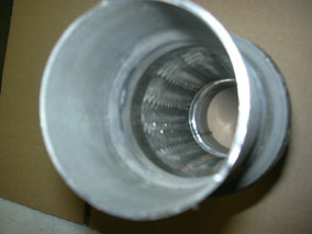
finally back to playing with the car. just wanted to post this little mod to the cats that Ryan sold me. I would think that most cats are made like this but I don't really have any idea. but just in case...
the pipe extensions that are welded on the ends of the cat to clamp or weld the cat onto your exhaust system may stick into the cat cavity a little bit. if it does like these do I would imagine that would cause an airflow restriction. so if you have a dremel tool with a cut off bit handy you can remove the part that sticks inside as shown here. you will have to cut the pipe extension off of the cat to get to this part. I needed the bends to start right at the ends of the cat so I cut mine off for that reason and then saw this "problem". if your looking to get all of the unnecessary restrictions removed and still have to use a cat this may help.

cat with pipe extension cut off outside of cat but still sticking into the cat about 3/4" or so.


cat after mod. I left a little bit of the pipe (approx 1/4") for strength and more metal to weld to.


here is the piece that was sticking into the cat.

[This message has been edited by cptsnoopy (edited 05-11-2012).]

IP: Logged
cptsnoopy
Member
Posts: 2585
From: phoenix, AZ, USA
Registered: Jul 2003


Feedback score:    (8)
Leave feedback


Total ratings: 60
Rate this member

Report this Post01-28-2005 09:16 PM Click Here to See the Profile for cptsnoopySend a Private Message to cptsnoopyEdit/Delete MessageReply w/QuoteDirect Link to This Post
the engine needed to go back into the car to figure out how to set up a flexible joint between the exhaust and the frame mounted mufflers. also a good time to try out Rodney's dual strut decklid support system. it looks and works great.

i decided to remove the decklid limit cable on the passenger side after seeing how well the gas struts work.

[This message has been edited by cptsnoopy (edited 05-11-2012).]

IP: Logged
PFF
System Bot
GSXRBOBBY
Member
Posts: 3122
From: Southern Indiana USA
Registered: Aug 2003


Feedback score: N/A
Leave feedback


Total ratings: 105
Rate this member

Report this Post02-02-2005 12:01 PM Click Here to See the Profile for GSXRBOBBYClick Here to visit GSXRBOBBY's HomePageSend a Private Message to GSXRBOBBYEdit/Delete MessageReply w/QuoteDirect Link to This Post
I see your oil add cap on the valve cover is really stuck in the back as mine will be, have you desided how your going to add oil? Also are you able to get to the oil dip stick?

------------------
Bobby from NW Indiana
93 Northstar and 5 speed Getrag
219customs@verizon.net
My 86 GT build thread
MY 88 Northstar build thread

IP: Logged
cptsnoopy
Member
Posts: 2585
From: phoenix, AZ, USA
Registered: Jul 2003


Feedback score:    (8)
Leave feedback


Total ratings: 60
Rate this member

Report this Post02-02-2005 01:09 PM Click Here to See the Profile for cptsnoopySend a Private Message to cptsnoopyEdit/Delete MessageReply w/QuoteDirect Link to This Post
I plan on putting a oil fill cap on the rear cam cover near the drivers side of the engine. I think a saw a picture of this on the chrfab website. It probably was the push in style of oil cap like I used to have on my 72 Vega. Not the greatest thing but it should be better than trying to get oil in near the firewall. I got an oil dipstick off a later model N* that fits in the hole and I have been bending it a little here and there to have it accessable near the water pump. I just need to get a clamp to hold it into place. I also need to verify that it gives an accurate reading.
IP: Logged
GSXRBOBBY
Member
Posts: 3122
From: Southern Indiana USA
Registered: Aug 2003


Feedback score: N/A
Leave feedback


Total ratings: 105
Rate this member

Report this Post02-02-2005 01:17 PM Click Here to See the Profile for GSXRBOBBYClick Here to visit GSXRBOBBY's HomePageSend a Private Message to GSXRBOBBYEdit/Delete MessageReply w/QuoteDirect Link to This Post
I was thinking about doing that but I was worried about the curve or angle taking away from the depth it would reach int the oil pan?

------------------
Bobby from NW Indiana
93 Northstar and 5 speed Getrag
219customs@verizon.net
My 86 GT build thread
MY 88 Northstar build thread

IP: Logged
cptsnoopy
Member
Posts: 2585
From: phoenix, AZ, USA
Registered: Jul 2003


Feedback score:    (8)
Leave feedback


Total ratings: 60
Rate this member

Report this Post02-02-2005 01:33 PM Click Here to See the Profile for cptsnoopySend a Private Message to cptsnoopyEdit/Delete MessageReply w/QuoteDirect Link to This Post
someday when i get a chance to clean and inspect the engine I will then fill it with oil and let you know if this oil dipstick i am using reads right. as of now I don't have any idea if it will be good or not...
IP: Logged
cptsnoopy
Member
Posts: 2585
From: phoenix, AZ, USA
Registered: Jul 2003


Feedback score:    (8)
Leave feedback


Total ratings: 60
Rate this member

Report this Post02-05-2005 08:54 PM Click Here to See the Profile for cptsnoopySend a Private Message to cptsnoopyEdit/Delete MessageReply w/QuoteDirect Link to This Post
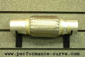
GSXRBOBBY, here is the exhaust tube with the ball and socket ends. I hope to use these springs to hold the joint together. if i do use this setup i will weld on anchors for the spings.

[This message has been edited by cptsnoopy (edited 05-11-2012).]

IP: Logged
GSXRBOBBY
Member
Posts: 3122
From: Southern Indiana USA
Registered: Aug 2003


Feedback score: N/A
Leave feedback


Total ratings: 105
Rate this member

Report this Post02-07-2005 11:28 AM Click Here to See the Profile for GSXRBOBBYClick Here to visit GSXRBOBBY's HomePageSend a Private Message to GSXRBOBBYEdit/Delete MessageReply w/QuoteDirect Link to This Post
I was looking at maybe using this to help with flex if needed. I think that setup will leak alot more then you think its going to?
http://motors.search.ebay.com/flex_W0QQsofocusZbsQQsbrftogZ1QQfrppZ25QQfromZR10QQsacatZ-1QQcatrefZC6QQftrtZ1QQftrvZ1QQsadisZ200QQfposZ46383QQsellerZ1QQsassZperformance-curveQQfsopZ 1QQfsooZ1QQcoactionZcompareQQcopagenumZ1QQcoentrypageZsearch

------------------
Bobby from NW Indiana
93 Northstar and 5 speed Getrag
219customs@verizon.net
My 86 GT build thread
MY 88 Northstar build thread

[This message has been edited by GSXRBOBBY (edited 02-07-2005).]

IP: Logged
cptsnoopy
Member
Posts: 2585
From: phoenix, AZ, USA
Registered: Jul 2003


Feedback score:    (8)
Leave feedback


Total ratings: 60
Rate this member

Report this Post02-07-2005 01:55 PM Click Here to See the Profile for cptsnoopySend a Private Message to cptsnoopyEdit/Delete MessageReply w/QuoteDirect Link to This Post
that's the flex joint i was told to stay away from. that's why the delima... next time I need to do a better job of engineering...

[This message has been edited by cptsnoopy (edited 02-08-2005).]

IP: Logged
ryan.hess
Member
Posts: 20784
From: Orlando, FL
Registered: Dec 2002


Feedback score: (1)
Leave feedback


Total ratings: 319
Rate this member

Report this Post02-07-2005 05:18 PM Click Here to See the Profile for ryan.hessSend a Private Message to ryan.hessEdit/Delete MessageReply w/QuoteDirect Link to This Post
There's going to be a next time???
IP: Logged
cptsnoopy
Member
Posts: 2585
From: phoenix, AZ, USA
Registered: Jul 2003


Feedback score:    (8)
Leave feedback


Total ratings: 60
Rate this member

Report this Post02-08-2005 12:54 AM Click Here to See the Profile for cptsnoopySend a Private Message to cptsnoopyEdit/Delete MessageReply w/QuoteDirect Link to This Post
 
quote
Originally posted by ryan.hess:

There's going to be a next time???

not if my wife has anything to say about it


IP: Logged
cptsnoopy
Member
Posts: 2585
From: phoenix, AZ, USA
Registered: Jul 2003


Feedback score:    (8)
Leave feedback


Total ratings: 60
Rate this member

Report this Post02-11-2005 06:38 PM Click Here to See the Profile for cptsnoopySend a Private Message to cptsnoopyEdit/Delete MessageReply w/QuoteDirect Link to This Post
 
quote
Originally posted by ryan.hess:

But the _real_ question... does it work?


Ryan, does this look right? I just hooked it up to my car battery and it seems to work ok. I have only run the calibration, it did not respond to "trace" correctly until I clicked on "last" then it worked ok and I could tweak it. I still need to check all of the output voltages etc... I don't have a clue on how to use it yet. that's next.

[This message has been edited by cptsnoopy (edited 05-11-2012).]

IP: Logged
PFF
System Bot
ryan.hess
Member
Posts: 20784
From: Orlando, FL
Registered: Dec 2002


Feedback score: (1)
Leave feedback


Total ratings: 319
Rate this member

Report this Post02-11-2005 06:59 PM Click Here to See the Profile for ryan.hessSend a Private Message to ryan.hessEdit/Delete MessageReply w/QuoteDirect Link to This Post
 
quote
Originally posted by cptsnoopy:
Ryan, does this look right? I just hooked it up to my car battery and it seems to work ok. I have only run the calibration, it did not respond to "trace" correctly until I clicked on "last" then it worked ok and I could tweak it. I still need to check all of the output voltages etc... I don't have a clue on how to use it yet. that's next.

I don't remember... IIRC, mine was spitting out lots of numbers when I was calibrating it...... But then, the problem is mine both worked and didn't work, so I don't remember if "spitting out numbers" was a good thing or not. Are you positive it's on COM 5? That sounds suspiciously high..... like for an internal modem or something. I would think it would be 1 or 2.

IP: Logged
cptsnoopy
Member
Posts: 2585
From: phoenix, AZ, USA
Registered: Jul 2003


Feedback score:    (8)
Leave feedback


Total ratings: 60
Rate this member

Report this Post02-11-2005 07:55 PM Click Here to See the Profile for cptsnoopySend a Private Message to cptsnoopyEdit/Delete MessageReply w/QuoteDirect Link to This Post
 
quote
Originally posted by ryan.hess:
Are you positive it's on COM 5? That sounds suspiciously high..... like for an internal modem or something. I would think it would be 1 or 2.

i am using a USB to serial adaptor and i am guessing that it set the port to com 5. I was talking to the wb02 with no problems other than the inital garbage it spit out until i hit "last". then it spit out what looked like a small amount of memory data in hex. after i got the reading to 8192 and 0, i hit "update" and that is when i took the screen shot. i take it there is several more hours of checking that it is putting out the right voltages before hooking it up? thx for the responses.

IP: Logged
ryan.hess
Member
Posts: 20784
From: Orlando, FL
Registered: Dec 2002


Feedback score: (1)
Leave feedback


Total ratings: 319
Rate this member

Report this Post02-11-2005 09:39 PM Click Here to See the Profile for ryan.hessSend a Private Message to ryan.hessEdit/Delete MessageReply w/QuoteDirect Link to This Post
 
quote
Originally posted by cptsnoopy:
i am using a USB to serial adaptor and i am guessing that it set the port to com 5. I was talking to the wb02 with no problems other than the inital garbage it spit out until i hit "last". then it spit out what looked like a small amount of memory data in hex. after i got the reading to 8192 and 0, i hit "update" and that is when i took the screen shot. i take it there is several more hours of checking that it is putting out the right voltages before hooking it up? thx for the responses.

Well that would do it then. Sounds like you're good to go then. I'd just check the test point voltages to make sure they're within spec, and go from there. Sounds like it works though.

IP: Logged
cptsnoopy
Member
Posts: 2585
From: phoenix, AZ, USA
Registered: Jul 2003


Feedback score:    (8)
Leave feedback


Total ratings: 60
Rate this member

Report this Post02-27-2005 05:18 AM Click Here to See the Profile for cptsnoopySend a Private Message to cptsnoopyEdit/Delete MessageReply w/QuoteDirect Link to This Post
here's a couple of pics to show what's been going on lately. the first two are of the adaptor for the fourth bell-housing bolt that does not line up. I extended this to a bolt hole in the diff case to help hold things together. it will also serve as an exhaust brace. (note: the correct length bolts still need to be purchased.) the third pic is of the lower exhaust brace. The fourth pic is of the general exhaust view. there are still a couple more welds that need to be ground down and brackets added for the ball joints. after that is done the cats are coming off and the whole system is going to get jet-hot coated.


[This message has been edited by cptsnoopy (edited 05-11-2012).]

IP: Logged
GSXRBOBBY
Member
Posts: 3122
From: Southern Indiana USA
Registered: Aug 2003


Feedback score: N/A
Leave feedback


Total ratings: 105
Rate this member

Report this Post03-15-2005 11:30 AM Click Here to See the Profile for GSXRBOBBYClick Here to visit GSXRBOBBY's HomePageSend a Private Message to GSXRBOBBYEdit/Delete MessageReply w/QuoteDirect Link to This Post
????
IP: Logged
cptsnoopy
Member
Posts: 2585
From: phoenix, AZ, USA
Registered: Jul 2003


Feedback score:    (8)
Leave feedback


Total ratings: 60
Rate this member

Report this Post03-15-2005 12:50 PM Click Here to See the Profile for cptsnoopySend a Private Message to cptsnoopyEdit/Delete MessageReply w/QuoteDirect Link to This Post
lol! i wondered when you would ask...

i made a little progress on the number 3 and 4 engine mounts. there just shock end bushings attached to the head and 1.5" square tubing to the cradle. I'm in Denver now so pics will be in a couple of days. after those are complete then i will take all the plugs out of the engine and make sure there is no rust in the cylinders. wheeeee!

[This message has been edited by cptsnoopy (edited 03-24-2005).]

IP: Logged
cptsnoopy
Member
Posts: 2585
From: phoenix, AZ, USA
Registered: Jul 2003


Feedback score:    (8)
Leave feedback


Total ratings: 60
Rate this member

Report this Post03-24-2005 07:41 AM Click Here to See the Profile for cptsnoopySend a Private Message to cptsnoopyEdit/Delete MessageReply w/QuoteDirect Link to This Post
since the dodge truck motor mounts have been torn apart by others I decided to go a different route with the middle motor mounts on my cradle.

this was the original idea.


this is plan "B". the dodge truck mount was removed in favor of a shock ring to limit the travel of the engine. I am hoping that this will help keep the other four mounts from tearing apart. there will be one of these at the rear middle of the engine also. as usual the hardware shown is temporary...


[This message has been edited by cptsnoopy (edited 05-11-2012).]

IP: Logged
RCR
Member
Posts: 4397
From: Shelby Twp Mi
Registered: Sep 2002


Feedback score:    (7)
Leave feedback


Total ratings: 102
Rate this member

Report this Post03-24-2005 10:52 AM Click Here to See the Profile for RCRSend a Private Message to RCREdit/Delete MessageReply w/QuoteDirect Link to This Post

What's wrong with this type of joint? Or this one in particular? This is the style that Darth recommends for his 3800 swaps. I was just going to piuck one up, so I'd like to hear about any issues.

TIA,
Bob

IP: Logged
Will
Member
Posts: 14226
From: Where you least expect me
Registered: Jun 2000


Feedback score: (1)
Leave feedback


Total ratings: 237
Rate this member

Report this Post03-24-2005 11:22 AM Click Here to See the Profile for WillSend a Private Message to WillEdit/Delete MessageReply w/QuoteDirect Link to This Post
 
quote
Originally posted by cptsnoopy:
this is plan "B". the dodge truck mount was removed in favor of a shock ring to limit the travel of the engine. I am hoping that this will help keep the other four mounts from tearing apart. there will be one of these at the rear middle of the engine also. as usual the hardware shown is temporary...

I'd whip up a plate to tie that into other surrounding bolt holes if I were you. Not sure I'd want the whole engine pulling on basically one hole...

IP: Logged
Previous Page | Next Page

This topic is 26 pages long:  1   2   3   4   5   6   7   8   9   10   11   12   13   14   15   16   17   18   19   20   21   22   23   24   25   26 
next newest topic | next oldest topic

All times are ET (US)

Post New Topic  Post A Reply
Hop to:

Contact Us | Back To Main Page

Advertizing on PFF | Fiero Parts Vendors
PFF Merchandise | Fiero Gallery | Ogre's Cave
Real-Time Chat | Fiero Related Auctions on eBay


Copyright (c) 1999, C. Pennock