plugged off my TB lines to simplify things - the holes were already tapped
as for the AC lines I'm going a route I don't think anyone else here has.. I'm splicing the new and the old together.. AC lines are very simple other than the special material of the flexible hose the connections are just your basic slide over and crimp - there are union connectors available that can use these same crimping ferules or special band clamps.. I purchased two stainless unions and 8 of these clamps (two on each end of each union - redundancy is a good thing in this case)
I'll post picks when the stuff arrives. its only about 20$ in materials and they are rating for 150psi
IP: Logged
10:20 PM
Darth Fiero Member
Posts: 5922 From: Waterloo, Indiana Registered: Oct 2002
Kohburn, the line that exits the underside of the TB and gets connected to the back of the water pump housing functions as a coolant bypass line. Removing/blocking it can result in excessive pressure building in the coolant system (and heater core circuit) when the thermostat is closed.
The other hole you plugged next to the thermostat outlet I believe is the supply line to the heater core.
Also, are you saying you are using components on your A/C lines that are only rated for 150psi? Your A/C system can see up to over 350psi during operation. You must use approved A/C-compatible materials and parts for the A/C system.
IP: Logged
10:28 PM
AaronZ34 Member
Posts: 2322 From: Colorado Springs, CO Registered: Oct 2004
The coolant flows up the engine, down the radiator in the 3.4L DOHC. The coolant from the heads mixes in the LIM, then some goes up to cirle around the throttle body, then it flows down, around the engine, bypassing the radiator. The water that flows through the TB does not pass through the radiator. Also in the LIM, water goes into that heater line that you blocked off. That is where water enters, and then it goes to the core, and returns back near the water pump, also bypassing the radiator. The rest of the water flows through the T-stat, then back to the radiator. The line that you plan on using for the heater is actually a suction line, it is at vacuum, the water pump sucks from it, it doesn't pump into it.
Here is a quick paint shcematic of the 3.4L DOHC coolant lines. This is a FWD setup, stock configuration, the top of the pic is the front of the engine. Feel free to ask if you have any questions.
Also, the TB coolant lines play a vital role. They prevent heater core damage when the enigne is at high RPM and at cold temperature. In these conditions, the T-stat is closed, and the water pump will build pressure at the heater core, damaging it. Therefore when this happens, the excess pressure is fed through the TB cooling lines instead.
------------------ 1988GT 5-speed Black with grey leather, I pick it up this May! 1992 Lumina Z34 5-speed 14.78 @ 92.688, high 13s at sea level 1992 Lumina Z34 5-speed Stock, new crate engine and trannsmission
IP: Logged
11:33 PM
Mar 4th, 2005
fieromadman Member
Posts: 2217 From: Oconomowoc WI, USA Registered: Jan 2003
darth, do you remeber or still ahve those numbers from the scan tool that i gave you? were the fuel trim specs and spark advance all within safe specs? Hopefully this weekend I will FINALLY be able to get around to hooking up the ECM's speedo wires. Now, i think that there is a buffered output on the ecm for the speedo, but i dont know whether or not i should be using this? With the original way that i had it wired, i just used the speedo sensor wires and split them, for the yellow output i sent it to thepurple ecm wire and then to the yellow one going to the speedo in the cabin, and for the purple, i went to the yellow on the ecm and purple into the cabin. It didnt work. I think (according to the diagrams that i have) that the 91-93 ecm wires should be backwards for the speedo, but do you know if this was continued to the 94-95 years? If it was, im thinking that i need to hook up the in-cabin ones to the ecm buffered output and the sensor backwards to the ecm, can you verify this?
Here is a quick paint shcematic of the 3.4L DOHC coolant lines. This is a FWD setup, stock configuration, the top of the pic is the front of the engine. Feel free to ask if you have any questions.
Also, the TB coolant lines play a vital role. They prevent heater core damage when the enigne is at high RPM and at cold temperature. In these conditions, the T-stat is closed, and the water pump will build pressure at the heater core, damaging it. Therefore when this happens, the excess pressure is fed through the TB cooling lines instead.
I knew if I kept posting about the coolant lines I'd eventually get more solid answers
So I should be able to route it like that so in general all the water flows out at 1 and in at 2 - and the T-stat is located at 1
as for the heater core overpressuring from the pump..has that ever actually happened?
I guess I can always peice back together the pipe that was already damaged when I removed it.
IP: Logged
07:52 AM
mrfixit58 Member
Posts: 3330 From: Seffner, Fl, USA Registered: Jul 99
Kohburn, the line that exits the underside of the TB and gets connected to the back of the water pump housing functions as a coolant bypass line. Removing/blocking it can result in excessive pressure building in the coolant system (and heater core circuit) when the thermostat is closed. ...
.
I don't think I agree (no flames, just a differet opinion). Fluid is not compressable. If you're concerned that the water pump will produce too much pressure and burst a hose, I would doubt that the pump the that efficient. The only hoses I ever seen burst was because they were rotten. Besides, the thermastat will bleed off excess pressure above 15-16 psi. All waterpumps that I've ever seen will only push all the fluid it can then cavitate. The restictions in the system act as the flow regulators.
The only way to build to much pressure is to overheat the fluid. Now, if you're saying that, by removing the tubing that goes from the throttle body to the water pump will lead to the motor overheating, then, that's different.
Roy
[This message has been edited by mrfixit58 (edited 03-04-2005).]
I don't think I agree (no flames, just a differet opinion). Fluid is not compressaable. If you're concerned that the water pump will produce too much pressure and burst a hose, I would doubt that the pump the that efficient. ALl waterpumps that I've ever seen will only push all the fluid it can then cavitate. The restictions in the system act as the flow regulators.
The only way to build to much pressure is to overheat the fluid. Now, if you're saying that, by removing the tubing that goes from the throttle body to the water pump will lead to the motor overheating, then, that's different.
Roy
This was my thought on the matter.. I have a hard time seeing the pump create more pressure than the actual heated system does on a regular basis. removing that line could never lead to overheating because once warmed upp the T-stat will open and flow to the radiator.
[This message has been edited by Kohburn (edited 03-04-2005).]
Originally posted by Darth Fiero: Also, are you saying you are using components on your A/C lines that are only rated for 150psi? Your A/C system can see up to over 350psi during operation. You must use approved A/C-compatible materials and parts for the A/C system.
got me on that one - ordering fittings with high pressure ratings forgot that high side pressure in PSI should be about 2.2 to 2.5 times outside air temperature in degrees F so If i hit a random 115 degree day (not in the last 4 years) I might hit 290psi
if it fails (or leaks) after that I'll swing by local radiator place and see if they will put the two together with new hose
[This message has been edited by Kohburn (edited 03-04-2005).]
IP: Logged
08:17 AM
Fierobsessed Member
Posts: 4782 From: Las Vegas, NV Registered: Dec 2001
I used to drive a 3.4 DOHC powered 85 2m4. It kept blowing heater cores. I had to add water one day because I didn't have any coolant laying around. The next day was freakishly cold, single digits. I lost the motor, and basicaly had to scrap the car. I would listen when they suggest that the 3.4 DOHC gets pressure surge to the heater core. The waterpump on the 3.4 DOHC's is actually quite strong, being that it is driven over 1:1, spins over 7000 RPM's and can build alot of head pressure when it tries to squeeze the entire coolant flow through the heater core only. My Quad 4 also has developed a habbit of eating heater cores, and that one has a 1/4" outlet oriface delibereatly welded in at the thermostat. Liquids may not be compressible, but Whenever you have a flow rate, and then apply resistance to it, pressure will build.
I used to drive a 3.4 DOHC powered 85 2m4. It kept blowing heater cores. I had to add water one day because I didn't have any coolant laying around. The next day was freakishly cold, single digits.
thats what I was looking for someone who has experienced it - but did you have that line blocked off?
because Drexter does
quote
Originally posted by DreXteR:
Here are a pic of mine.
Dre
[This message has been edited by Kohburn (edited 03-04-2005).]
IP: Logged
08:54 AM
Fierobsessed Member
Posts: 4782 From: Las Vegas, NV Registered: Dec 2001
Mine was a 96, I don't remember it having any coolant lines going to the TB. The line he has blocked off is the coolant return line from the heater core. I had it hooked up like it was supposed to be. In an 88 I suppose you would block that off since the heater core return T's into the radiator return line before the water pump inlet.
[This message has been edited by Fierobsessed (edited 03-04-2005).]
Mine was a 96, I don't remember it having any coolant lines going to the TB. The line he has blocked off is the coolant feed line from the heater core. I had it hooked up like it was supposed to be. In an 88 I suppose you would block that off since the heater core return T's into the radiator return line before the water pump inlet.
the line blocked off is where the metal tube runs from the top of the engine down to. the heater core return line is by the TB pointing towards the trunk on the pre-96 - not sure how different the 96-97 is for heater lines..
(don't take anything as being argumentative, I'm just not one to take everything I hear and believe it right away without some more evidence to back it up so i play devil's advocate)
[This message has been edited by Kohburn (edited 03-04-2005).]
IP: Logged
09:17 AM
AaronZ34 Member
Posts: 2322 From: Colorado Springs, CO Registered: Oct 2004
the line blocked off is where the metal tube runs from the top of the engine down to. the heater core return line is by the TB pointing towards the trunk on the pre-96 - not sure how different the 96-97 is for heater lines..
(don't take anything as being argumentative, I'm just not one to take everything I hear and believe it right away without some more evidence to back it up so i play devil's advocate)
Wrong again
The line that he has blocked off is the TB coolant return line. The heater core return line enters right on the other side of the one he has blocked off. The line out of the TB pointing towards the trunk is the heater core feed line.
As for your new schematic, that will work perfect. The reason I bought up the pressure buildup is that the Fieros make a habit out of destroying heater cores, and if they are already bad, why stress them more? For mine, I'll be using an electric water pump that is thermostatically activated, so it acts as the T-stat, then I remove the stock t-stat and run without one. This way it will not overpressurize.
wrong? what? hey quit editing my quote :P
interesting about the waterpump - how much did that cost ya?
I think I found a solution I'm happy with.. a pressure relief by-pass valve.. I'll T into the lines up at the heater core and put it between them.. if the pressure differential is over 0-20 (adjustable) psi it will open and bypass the heater core.
[This message has been edited by Kohburn (edited 03-04-2005).]
IP: Logged
10:58 AM
AaronZ34 Member
Posts: 2322 From: Colorado Springs, CO Registered: Oct 2004
It ruly is an AWESOME pump, it will flow much mroe than stock, can be programmed to continue runnign after shut off, acts as an adjustible T-stat, so it flows at hundreds of different speeds dependent on engine temperature, etc. It is really nice, but for the price it'd better be.
That pressure relief valve would work fine. Have you thought about using an electric water pump? You may want to. Just build a steel plate to cap off the housing, and move the suction lines to before the pump. You will also have to figure out a way to reroute your serpentine, but this isn't hard to do.
looks like your basic turbo compressor housing - probably a plastic housing with metal turbine sealed and driven by an electric motor I can see wiring up a speed controller with multiple inputs from engine temp sensor, tach input etc.
seems to me a basic variable speed controller could be controlled from the temp sensor with the coolant fan switch as a backp incase of temp sensor failure
IP: Logged
01:58 PM
Darth Fiero Member
Posts: 5922 From: Waterloo, Indiana Registered: Oct 2002
I don't think I agree (no flames, just a differet opinion). Fluid is not compressable. If you're concerned that the water pump will produce too much pressure and burst a hose, I would doubt that the pump the that efficient. The only hoses I ever seen burst was because they were rotten. Besides, the thermastat will bleed off excess pressure above 15-16 psi. All waterpumps that I've ever seen will only push all the fluid it can then cavitate. The restictions in the system act as the flow regulators.
The only way to build to much pressure is to overheat the fluid. Now, if you're saying that, by removing the tubing that goes from the throttle body to the water pump will lead to the motor overheating, then, that's different.
Roy
Roy, I think you are confusing the radiator cap with the thermostat. the radiator cap bleeds off pressure above the rated amount, not the thermostat. In fact, take a look at how the conventional thermostat operate, it has to open against path of flow. If you disable the coolant bypass on an engine, you can actually cause a condition that may prevent the thermostat from opening!
As far as fluid pressure the easiest way to explain it is go turn on your garden hose and try to cover the end of the hose with your hand so no water can come out. I bet you can't do it. Furthermore, if what you were saying were true, you would never be able to have oil pressure in an engine. The oil pump does NOT pump air, it pumps liquid oil.
Listen, a while back there were a rash of people running 3800's and stock Fiero thermostat housings that were bending thermostats. It turns out that most of the people that were experiencing this had removed their stock tensioner bracket (which contains an internal coolant bypass passage). I can guarantee you that IF you remove or disable the coolant bypass on the 3.4 DOHC engine has I and AaronZ34 have explained it, you WILL have cooling system issues. In fact, you might blow out more than hoses.
A simple pressure relief valve tee'd into the heater lines is not advisable. That pressure release valve will do nothing but put more stress on the heater core than it would normally see when the engine rpm's are high and the thermostat is closed. You need to have a seperate coolant bypass line hooked up, period.
IP: Logged
02:08 PM
Darth Fiero Member
Posts: 5922 From: Waterloo, Indiana Registered: Oct 2002
darth, do you remeber or still ahve those numbers from the scan tool that i gave you? were the fuel trim specs and spark advance all within safe specs? Hopefully this weekend I will FINALLY be able to get around to hooking up the ECM's speedo wires. Now, i think that there is a buffered output on the ecm for the speedo, but i dont know whether or not i should be using this? With the original way that i had it wired, i just used the speedo sensor wires and split them, for the yellow output i sent it to thepurple ecm wire and then to the yellow one going to the speedo in the cabin, and for the purple, i went to the yellow on the ecm and purple into the cabin. It didnt work. I think (according to the diagrams that i have) that the 91-93 ecm wires should be backwards for the speedo, but do you know if this was continued to the 94-95 years? If it was, im thinking that i need to hook up the in-cabin ones to the ecm buffered output and the sensor backwards to the ecm, can you verify this?
Thanks Jeff
Jeff, I can't seem to find that data you sent me, could you resend it?
As far as the speedo wiring, you don't need to hook the speedo up to the PCM. You can, but then you would have to build an interface circuit to get it to work. I suggest just splicing in the PCM's VSS input wires to the Fiero's VSS wires. If you hook yellow to yellow and purple to purple but the scan tool is not registering a VSS signal or you speedo stops working, try flipping the wires around. I have found that on some 3.4 DOHC computers the VSS wiring is backwards.
IP: Logged
02:15 PM
fieromadman Member
Posts: 2217 From: Oconomowoc WI, USA Registered: Jan 2003
As far as that data goes, I think that Im gonna have to put it on the scan tool again unless I can find the e-mail where I sent it to you, but I doubt that! Once I get the speedo wires hooked up ill tell you how it behaves and send the chip back to you for further programming. Thanks for your patience once again, and thanks for hacking that 94-95 code!
Originally posted by Darth Fiero: A simple pressure relief valve tee'd into the heater lines is not advisable. That pressure release valve will do nothing but put more stress on the heater core than it would normally see when the engine rpm's are high and the thermostat is closed. You need to have a seperate coolant bypass line hooked up, period.
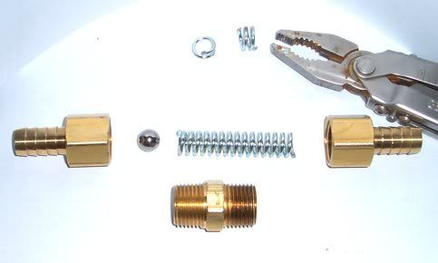
Explain how no relief valve is better than having a relief valve.. it will bypass the heater core when pressure on the highside increases above desired amounts. all it is is a one way check valve with a high cracking pressure and its adjustable - made one today from brass fittings, a stainless steel ball bearing and a spring cut to adjust .. tested cracking pressure with compressed air - this is a half in line.
[This message has been edited by Kohburn (edited 03-04-2005).]
IP: Logged
05:15 PM
mrfixit58 Member
Posts: 3330 From: Seffner, Fl, USA Registered: Jul 99
Roy, I think you are confusing the radiator cap with the thermostat. the radiator cap bleeds off pressure above the rated amount, not the thermostat.
.
Yep. Your right. I meant radiator cap (should know better that to type an run )
quote
Originally posted by Darth Fiero:
In fact, take a look at how the conventional thermostat operate, it has to open against path of flow. If you disable the coolant bypass on an engine, you can actually cause a condition that may prevent the thermostat from opening!
Thank-you for explaining that. I'm having send thoughts about removing the bypass. But, I would really like to get rid of the throttle body heater. Living in Florida, it serves very little purpose. I was thinking of tapping the holes and inserting a brass plug. The benifit to me is, it would allow me to remove the intale plenum without opening up the cooling system. Plus, if I want to go turbo, who wants to add more heat?
quote
Originally posted by Darth Fiero:
As far as fluid pressure the easiest way to explain it is go turn on your garden hose and try to cover the end of the hose with your hand so no water can come out. I bet you can't do it. Furthermore, if what you were saying were true, you would never be able to have oil pressure in an engine. The oil pump does NOT pump air, it pumps liquid oil.
Again, true. But the pressure is a factor of the pumps ability to push the liquid through s restriction (as in your garden hose example). However, the pump will reach a finite pressure whether partually or fully blocked. Pressure only starts to drop when you've removed enough restriction to allow it to flow freely. Kind like the same garden hose example... but instead of your thumb, stick it into a 2" pipe with a 2" opening. Lots of fluid flow, but very llittle pressure... until you try to cap it off.
quote
Originally posted by Darth Fiero:
Listen, a while back there were a rash of people running 3800's and stock Fiero thermostat housings that were bending thermostats. It turns out that most of the people that were experiencing this had removed their stock tensioner bracket (which contains an internal coolant bypass passage). I can guarantee you that IF you remove or disable the coolant bypass on the 3.4 DOHC engine has I and AaronZ34 have explained it, you WILL have cooling system issues. In fact, you might blow out more than hoses.
Again, sage advice.
quote
Originally posted by Darth Fiero:
A simple pressure relief valve tee'd into the heater lines is not advisable. That pressure release valve will do nothing but put more stress on the heater core than it would normally see when the engine rpm's are high and the thermostat is closed. You need to have a seperate coolant bypass line hooked up, period.
Know here, I'm with Kohburn. Maybe it's because I'm not clear enough on the coolant piping. Please 'splin it to me. The pressure valve seems like a reasonable idea. Engine oil pumps use this method to limit oil pressure!?!
The reason why I advised you NOT to use a pressure relief valve is because your valve is going to have a restriction in volume of flow. If you look at the factory bypass line at the smallest point it measures about 3/8-1/2"; which is OPEN all of the time the thermostat is closed. Besides that, you are going to force ALL of the coolant flow thru the heater core circuit while the thermostat is closed. As setup from the factory, coolant ALWAYS has 2 paths it can flow at the same time. HEATER-BYPASS and HEATER-RADIATOR. Removing the bypass line will disable one of these paths.
The bypass system works this way: When the thermostat opens, an interal passage in the lower intake manifold gets sealed off by the cup on the back of the thermostat, thus limiting flow thru the bypass line so there is still sufficient flow thru the heater core. The heater hose is open and allows flow all of the time regardless of thermostat operation. When the thermostat is opes, the bypass circuit gets shut off and most of the flow is forced to travel up to the radiator.
I guess I am having a hard time understanding WHY you wish to remove the bypass circuit. GM went to a lot of trouble designing this setup (and had no problems with it) and you wish to disable it and replace it with a home-made pressure relief valve? You can go ahead and do it your way but I am warning you that you are running the risk of causing damage to either your engine or your heater core circuit.
As far as the amount of pressure the stock water pump can put out, why don't you hook one up to a pressure gauge and run it at 7000rpm and dead-head the pump. Let me know what happens. I bet there is going to be more pressure there than you think.
Something else to keep in mind, the free-er flowing the coolant system, the less HP loss driving the water pump. If you block or disable the bypass line then you are causing a restriction--even with the use of a relief valve in the heater circuit. Doing this will force the pump to try to pump the same volume of fluid it would normally pump thru two open lines, thru one -- all to the heater core, at least when the thermostat is closed. Pressure will increase and it will require more HP to drive the water pump.
Again, it is your engine and if you think you have a better idea than the GM designers of this engine did then be my guest and try it.
I thought about doing it to avoid some of the pain in the ass piping I have to do... but what Darth said makes sense - that pump is pushing a fluid around in a loop - when the thermo is closed you can't simply cap off the flow. Even with slippage in the pump (non positive displacement), it's going to take a buttload of power to keep it churning away which uses up a whole lot of power very quickly - a waterbrake. I bet whatever is holding all that pressure back is also going to be pissed off.
Kohburn - the idea sounds alright, but try connecting your bypass valve to the garden hose and see if you get any flow out of it, and how much pressure you get behind it? Not downing your idea, I don't see a problem with your concept. However, I bet that even if you took the ball out, it won't flow enough to save your heater core in the event of a pressure surge or hydraulic shock. Remember that the heater core is made out of glorified aluminum foil, and it has tens and hundreds of square inches of surface area by nature. Just a few pounds and it's gonna be in a world of hurt I think. You gotta have something that flows really good. If you insist on doing this... why not make a nice, big, fat bypass with like 1/2" or 5/8" connectors on each side. You have CNC right?
Again, not trying to down anybody here, I'm just sharing my opinion.
------------------ Chris
Blue 1987 GT Getrag 5 speed, 1" lowering springs, 225 50R16 rims and tires, Fiero Store 9 3/4" HD clutch (Halfway through a 3.4L TDC Swap!) Silver 1986 2m4 THM 125c automatic (Current commuter) Black 1985 2m4 SE Isuzu 5 speed (no paperwork)
Originally posted by Darth Fiero: Something else to keep in mind, the free-er flowing the coolant system, the less HP loss driving the water pump. If you block or disable the bypass line then you are causing a restriction--even with the use of a relief valve in the heater circuit. Doing this will force the pump to try to pump the same volume of fluid it would normally pump thru two open lines, thru one -- all to the heater core, at least when the thermostat is closed. Pressure will increase and it will require more HP to drive the water pump.
As you so plainly pointed out - the thermostat restricts flow to the by-pass line once the engine is warm anyways - who tries to get the maximum HP out of a cold engine?
as for the line size it will mostly increase fluid velocity until it hits a restriction at which point it starts to build backpressure - if that is at the heater core the backpressure is simply bled off essentially reducing the restriction.
I don't know why you seem to be so upset about the subject - its all an excersize in what can be done. The main reason I started down this road is because my metal bypass line was crimped and damaged and I wanted to clean up the engine. If it turns out to be a big problem I can always fab a new line or splice a repair into the original one.
Originally posted by Blue Shift: Kohburn - the idea sounds alright, but try connecting your bypass valve to the garden hose and see if you get any flow out of it, and how much pressure you get behind it? Not downing your idea, I don't see a problem with your concept. However, I bet that even if you took the ball out, it won't flow enough to save your heater core in the event of a pressure surge or hydraulic shock. Remember that the heater core is made out of glorified aluminum foil, and it has tens and hundreds of square inches of surface area by nature. Just a few pounds and it's gonna be in a world of hurt I think. You gotta have something that flows really good. If you insist on doing this... why not make a nice, big, fat bypass with like 1/2" or 5/8" connectors on each side. You have CNC right?
the bypass IS 1/2" INSIDE diameter at the narrowest point - the ball valve itself is 3/8" diameter inside a 5/8" diamter shaft - this leaves more cross sectional area around the ball than the narrowest point in the system. Currently I have the spring tension set to start opening at about 2-5psi but not hit full open without about 15psi - so as long as the heater core can handle twice the standard lowside pressure of 15psi (From heat expansion) then it'd be fine. I plan to do a fluid test another time - no fittings for a garden hose at this time.
IP: Logged
11:15 PM
Mar 5th, 2005
Darth Fiero Member
Posts: 5922 From: Waterloo, Indiana Registered: Oct 2002
As you so plainly pointed out - the thermostat restricts flow to the by-pass line once the engine is warm anyways - who tries to get the maximum HP out of a cold engine?
as for the line size it will mostly increase fluid velocity until it hits a restriction at which point it starts to build backpressure - if that is at the heater core the backpressure is simply bled off essentially reducing the restriction.
I don't know why you seem to be so upset about the subject - its all an excersize in what can be done. The main reason I started down this road is because my metal bypass line was crimped and damaged and I wanted to clean up the engine. If it turns out to be a big problem I can always fab a new line or splice a repair into the original one.
I am not upset, rather I am just frustrated because I guess I am having a hard time explaining to people why I think it is a bad idea. Before I explain this another way, let me first clarify your point about the thermostat.
The thermostat almost never stays completely open when the engine is at operating temp. While you say you won't beat on your car while the engine is cold, the thermostat can still close while the engine is hot. It doesn't have to completely close to cause a problem. When you are moving down the highway the thermostat is constantly opening and closing in an attempt to control coolant temp. The cool air coming thru the radiator at highway speed is more than enough to cool the engine down past the point your thermostat closes. So as you can see, even though you may not beat on your engine while it is cold, your thermostat can still close on you when it is at operating temp and if you are beating on it that is bad news.
About your bypass system. There is something you are overlooking here. Lets take the radiator circuit out of the loop and assume the thermostat is closed. At this point, there are TWO seperate paths for coolant to flow. Thats TWO seperate 5/8" diameter hoses/tubes to cycle the coolant. Even with your pressure relief valve present, you have cut this system down to ONE 5/8" diameter hose/tube. Thats 1/2 the available circuit to handle the same amount of volume that would normally travel thru TWO seperate circuits. It doesn't take a slide rule to figure out that your head pressure (and pump HP loss) is going to increase, as well as stress in the heater core circuit. Pressure relief valve or not that circuit is going to be subjected to twice the normal fluid volume flow which is going to result in more pressure.
Again, I am not trying to knock anyone's ideas on the subject but sometimes I don't think it is a good idea to try to reinvent the wheel. Again, if you feel your method is sound, go ahead and try it. All I am saying is there is a reason why GM put that bypass system in there. They wouldn't spend money on a whole other circuit if they didn't feel it was necessary.
All good points, but you put a lot more faith in GM's engineers than I do. I will probably still put the pressure bypass valve up at the heater core since a reduntant system never hurts. However I really have no clue why GM put in a seperate bypass circuit thats entire purpose it just to bypass the thermostat. All that line needs to do is go around the thermostat and plug back into the radiator line. I'm not trying to cut out the TB circuit - just trying to clean up the engine bay a bit and decide on a solution for my broken bypass line. yes I could run it all rubber but that would look like crap.
Do you see any reason why plugging that line from the TB back into the main radiator line after the thermostat wouldn't work?
this is a VERY interesting subject; I especially like the fact that people are staying cool and trying to be logical and methodical.
Kohburn I agree that THAT coolant line really looks......well........unusual. And my thought was to remove it or try to replace it with something - I am just not sure what, and I am still thinking about this. But in the meantime, I have a couple of thoughts on this topic that might be worth a bit more thought or concern or discussion......???
As a small note on the arithmetic - and maybe I am not reading it right, either; but if your stock bypass line is 5/8", then replacing it with a 1/2" is fairly close. A 3/8" ball inside a 5/8" coupling would equal the flow area (if that is what you are saying) for a 1/2" line. A 5/8" line has about 0.307 sq in of free area; the 3/8" ball will subtract about 0.11 sq in; so the remaining free flow area will be about 0.196 sq inches. An open 1/2" line is also about 0.196 sq inches, just to put some dimensions on them. You have a 95 model, I think, so I am going to go out to see how it might differ from my 92 if at all.
Anyway, that's not my point(s) here; what I am hoping to do is think outside the box a bit from the direction we are going, just in case..... and ignore the heater core for a minute as a prime suspect Aaron mentioned a while back that the line in question is actually a 'return' from the heads. It gathers flow FROM the heads in the LIM and sends it directly back to the pump, according to the diag, IIRC. As the principle source of heat in the engine (the heads) that makes it worth special consideration, at least to me. The other item is that thermostats are notoriously low-quality; I have owned a LOT of cars, and time and experience has taught me to distrust even NEW thermostats until they prove themselves. I expect that anyone who has owned more than 5-10 cars has bought a new thermostat that was faulty. I don't expect anyone has an objection to that ( again ) So in my experience they are NOT a 'high reliability' item and thus, worst-case scenarios should at least be considered when a thermostat is involved. Is there any chance this idea was in the back of anyone's mind when they came up with the 'head' bypass? I dunno, of course, but ensuring a reliable, dedicated flow for the (important) heads might be a thought.. Maybe running the heads on the hot side would affect some thermal expansion (and thus clearances etc) somewhere? Again, I am speculating.
If you do go ahead with the bypass Kohburn then I hope you will post if something does go wrong; I do NOT wish ill on you or anyone but everyones experience is what helps here, and 'avoiding bad experiences' is the main point of this forum, or at least one of them. And maybe all this is not about the heater core at all, but they have simply fallen victim to another requirement/design idea entirely. my two cents. Next?
[This message has been edited by fiero308 (edited 03-05-2005).]
IP: Logged
12:05 PM
Darth Fiero Member
Posts: 5922 From: Waterloo, Indiana Registered: Oct 2002
As a small note on the arithmetic - and maybe I am not reading it right, either; but if your stock bypass line is 5/8", then replacing it with a 1/2" is fairly close. A 3/8" ball inside a 5/8" coupling would equal the flow area (if that is what you are saying) for a 1/2" line. A 5/8" line has about 0.307 sq in of free area; the 3/8" ball will subtract about 0.11 sq in; so the remaining free flow area will be about 0.196 sq inches. An open 1/2" line is also about 0.196 sq inches, just to put some dimensions on them.
You are forgetting something though. In my previous post I pointed out that as designed from the factory, the coolant has TWO seperate 5/8" lines to pass thru at minimum. The way Kohburn has it setup with this press relief valve, there is only one SINGLE 5/8" line the coolant has to travel thru until it gets to the heater core/press relief valve. You could replace the heater core circuit hard lines on the car with larger ones but then you would have to increase the size of the inlet/outlet fittings on the engine as well, otherwise you could have a coolant head pressure build up within the engine.
Fiero308, ALL engines have some kind of coolant bypass system. Some like the 3.4 DOHC and 3800 use an external bypass, while others like the SBC V8 have an internal passage. I don't think GM would have spent the time and money researching and developing these bypass systems unless they were absolutely necessary.
i see your point Darth - but can you see any reason they did the bypass tube instead of this: (minus the pressure relief valve of course)
:edit: ok i thought of a possible reason - which would be to help the heads warm up and reach operating temps faster by bypassing the radiator - that little tidbit may have just made me convince myself to stick with the stock bypass setup - I just preffer to know the reasoning behind things rather than have blind faith in GM -
[This message has been edited by Kohburn (edited 03-05-2005).]
IP: Logged
02:03 PM
PFF
System Bot
Erik Member
Posts: 5628 From: Des Moines, Iowa Registered: Jul 2002
:edit: ok i thought of a possible reason - which would be to help the heads warm up and reach operating temps faster by bypassing the radiator - that little tidbit may have just made me convince myself to stick with the stock bypass setup - I just preffer to know the reasoning behind things rather than have blind faith in GM -
Its ok. Again, no hard feelings and please don't take me the wrong way; I am not trying to rain on your parade, just trying to explain why it is there and why it shouldn't be removed.
Its ok. Again, no hard feelings and please don't take me the wrong way; I am not trying to rain on your parade, just trying to explain why it is there and why it shouldn't be removed.
non taken - I enjoyed the debate - gotta keep the old gears turning
[This message has been edited by Kohburn (edited 03-06-2005).]
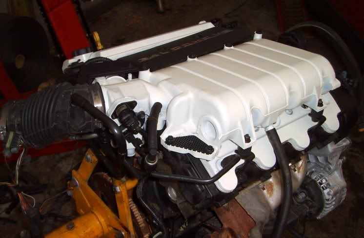
was able to repare the old by-pass line for the most part - slight kink to it (it had been folded in half) - then sprayed it with rust converter on all the bare metal (non rusty) then sprayed my usual low-gloss black hightemp paint on it.. can't see it in these pics - but you can see some of darth's inspiration in my work. I have since relocated the purge solenoid to the EGR location. mounted the 2bar MAP sensor where the powerstearing was and started wiring the map plug into the lines as well as relocate the O2 sensor plug to where the EGR used to be.. its really cleaning up the engine bay area.
My timing belt cover had been broken in a few areas so I took out the trusty olf soldering gun and attached the plastic welding tip and went to town - after some smoothing and light sanding its not noticable with out looking closely.
IP: Logged
07:06 AM
AaronZ34 Member
Posts: 2322 From: Colorado Springs, CO Registered: Oct 2004
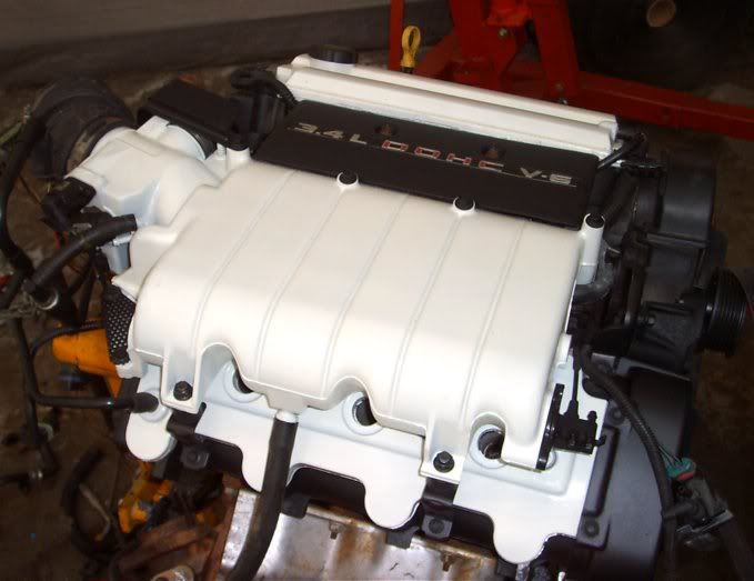
yeah; I like those covers/finish; is that in fact white paint (looks semi flat?) or is it a very fine grit-blasted finish? I cant tell but it looks really nice!
Dammit, you are confusing me. First I wanted chrome, then black on red, now white on red...argggg
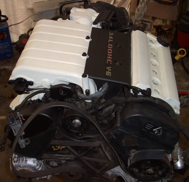
yes it is infact white - I figured i'm gonna paint the car white - why not the engine too - its gloss white on the valve covers and plenum with the cam cariers etc all painted a low-gloss black.. loose better in person..
the white is infact very glossy but I didn't polish the plenum down first so it has the casting texture it makes it look a little flat to the camera. when I go turbo I'll be swapping on a modified plenum so I'll sand that one smooth first and remove any casting or *cough* welding *cough* seams off.
I used a 4 cylinder throttle cable and it worked great. Slides right onto the mount on the throttle body and gives enough length to route it away from everything.
------------------ Chris 3.4 TDC SWAP COMPLETED...this is going to be a fun car