Roy, I can only do chips for the 91-93 computers (16149396 ECM) at this time. But if you have a 95 harness it should not be too hard to get that harness to work with the older ECM. I have pinouts and diagrams for both.
...
Do you know if the 91-93 ECM is the only change necessary? Will all the other sensors work?
IP: Logged
09:02 AM
Darth Fiero Member
Posts: 5922 From: Waterloo, Indiana Registered: Oct 2002
The only other difference is that you will not use the MAF sensor, cam sensor, or crank trigger at the balancer (if you have them), instead you will just use a map sensor.
The 94-95 PCM's were sequential fire injection and used the cam sensor and crank sensor at the balancer for injector timing; the 91-93 ECM does not use these. The coil pack still gets it's crank sensor signal from the same crank sensor located in the center of the block in the rear.
IP: Logged
12:33 PM
ltlfrari Member
Posts: 5356 From: Wake Forest,NC,USA Registered: Jan 2002
The 94-95 PCM's were sequential fire injection and used the cam sensor and crank sensor at the balancer for injector timing; the 91-93 ECM does not use these. The coil pack still gets it's crank sensor signal from the same crank sensor located in the center of the block in the rear.
What that means roy is that you need to wire Injectors 1,3,5 together and connect them to pin D13 (I think) on the 9396 ECM and injectors 2,4,6 together and connect to pin D19 on the ECM (pretty sure I got te pin nos correct but don't have my manuals to hand). I just connected the wires together on the 6 pin connector on the ECM side so that I did not have to cut the engine sub harness. The nice thing about this is that with power on you can earth each pin on the sub harness and it will trip the corresponding injector, thus allowing you to a) test the injectors and b) prime the system which I find usefull at the mo since it's a bugger to start first time. Ps engine back in, hopefully I'll be trying mine again in a couple of days (fingers crossed). I'll post my wiring diagrams on my web site some time soon.
Thanks guys. I'll convert to 91-93 if I have to but it was my understanding that, as long as the computer was OBD1, the chip could be hacked. Do any of you know of anyone running the 94-95 computer with a manual tranny?
Roy
IP: Logged
07:52 AM
ltlfrari Member
Posts: 5356 From: Wake Forest,NC,USA Registered: Jan 2002
I couldn't find any. I was considering the same thing originally. I even started to map out the auto program from the prom but I decided using the earlier ecm was just plain easier. I might get around to doing the auto prom later once I have this beast running but don't hold your breath for it from me
as for the oil pan clearance mentioned earlier, The bottom of my oil pan is about 1 inch above the bottom oy cradle. I am using stock tranny brackets with WCF tranny and engine mounts and my own custom front engine mount (egine site leve lthough) so I could probably drop it that inch. I think the axles would clear the cradle on full shock extension.
thanks for the bump. sorry for the delay in the swap but needed some time away from the garage so I went to the lake this weekend. Anyway, I am back at it, working on the exhaust. Pics will be soon following.
IP: Logged
06:02 PM
May 22nd, 2004
Darth Fiero Member
Posts: 5922 From: Waterloo, Indiana Registered: Oct 2002
The Y-pipe is done and covered in header wrap. As you can see, I had to route the exhaust from the rear of the engine around the left outside of the transaxle. Due to the unique shift cable placement on the 4-speed Muncie, there is little room for a pipe to fit under the throttle body. It could have been done but the shift cables would have ended up too close to the exhaust crossover which would have created some problems later on.
I used part of the factory 3.4 DOHC crossover pipe, namely the flanges on the ends and the factory expansion joint (flex). You can see between the rear manifold flange and flex joint I welded in an EGR feed from a 3800. The stock 3.4 DOHC EGR tube will bolt to this. I also welded an O2 bung right in where the two sides of the exhaust come together so it is reading off both banks. Since everything is in header wrap, I could probably use a standard 1-wire O2 sensor in this car but I have so many low-mile heated O2 sensors lying around, that is what is going in. Besides that this car may have to pass an emissions test and the heated O2 will allow the engine/ECM to go into closed loop sooner which means cleaner cold-warmup emissions.
For the y-pipe to the rest of exhaust flange I used the stock 3.4 DOHC downpipe flange which is 2.5" dia, and the manifold side flange and doughnut gasket from an old 3800 manifold. Along with the spring loaded bolts, this will allow the engine to move a little and not put stress on the the exhaust system. I have the exhaust built up to the muffler and am using the factory spring hangars for support. I am taking a break from the exhaust for a while and working on some other things.
Next thing to do is the idler pulley (Power Steering Pump Delete). I went out to the junk yard and looked at several GM engines. Some have an idler pulley that is simply bolted to the engine or a bracket somewhere. Most will have a bolt, washer, and spacer that has a shoulder on it. This is what you need in conjunction with Idler Pulley p/n 45971 (factory air brand) and a few 3/8" ID flat wasters to use on the 3.4 DOHC.
Once you have all the parts you will need a 10mm x 1.50 metric thread tap. All you need to do is tap the top p/s pump hole on the serpentine bracket. The hole is already drilled to the correct size.
Once the hole is tapped, you can install your parts. In my case, the aluminum spacer that I got that has the shoulder on it is also stepped in on the backside which means it would not sit flat on the bracket. Two 3/8" grade 8 flat washers fit nicely and spaced the pulley out just right.
Now all I need to do is install the A/C pump and serpentine belt.
Darth, I know you've been working like a madman on yellowatero's car, in fact you've been so busy I hardly see you, but I would really like to take my fiero to the dell's June 5th...it's not looking quite so possible anymore, although I have seen you do a complete swap in 8 days, but of course that was to your own car! Will mine at least be done in time for Fieros at Auburn or if I really hope...the hot rod power tour? On the bright side this 3.4 is looking like it is coming together very well. I've seen every swap Darth's done and I have to say I think this is one of his favorites, it really shows in the quality of your work how much you love what you do and I find that very rare...ok I'm just sucking up to get my car done!!! I'll cook and do the dishes!
IP: Logged
12:00 PM
May 25th, 2004
Darth Fiero Member
Posts: 5922 From: Waterloo, Indiana Registered: Oct 2002
Sorry it has been a while since I have posted pics. Right now I am working primarily on the wiring and cooling system so there is not much to show. However I did snap a few photos tonight so I could keep this thread going.
Here is a side view pic of the engine. NOTE: this is not the intake I will be using, RAREW66 is supposed to be finished with the intake sometime tomorrow. Notice the location of the MAP sensor right behind the idler pulley. What a great place to put it in order to hide the engine valley.
There a still a few small things to do like hook up the PCV valve and intake to heater core pipe hose and water outlet hose that goes to the driver's side tube. The wiring in the engine compartment is done with the exception of getting a new, longer ground cable from GM since the stock 2.8L one is really too short. I could use it on this engine but it would look like crap.
I cranked it over today to get some oil pressure; didn't take long. That early FWD gear reduction Delco-Remy/Denso "prototype" starter really sounds cool.
IP: Logged
11:48 PM
m0sh_man Member
Posts: 8460 From: south charleston WV 25309 Registered: Feb 2002
if someone were to send you the fiero wiring harness and the 3.4L DOHC wiring harness could you patch them together to make them work, then send it back? i can make minor changes in the wiring, but id have to pay someone to figure out the hard stuff, but when it comes to just making the wires longer or shorter, i can do that
im planning on a 3.4L DOHC in a 88 coupe with GT body and rear swaybar.
is the DOHC the easiest of the swaps wiring wise?
matthew
IP: Logged
11:57 PM
PFF
System Bot
May 26th, 2004
RAREW66 Member
Posts: 1119 From: Davenport, IA USA Registered: Jun 2001
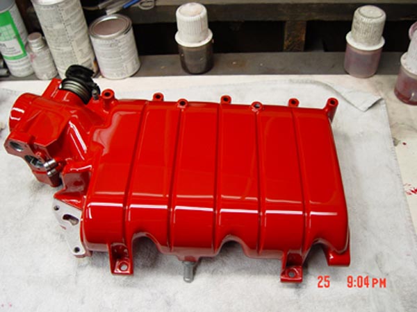
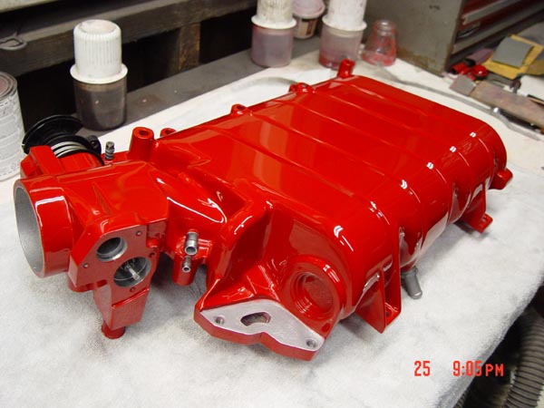
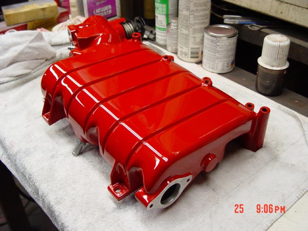
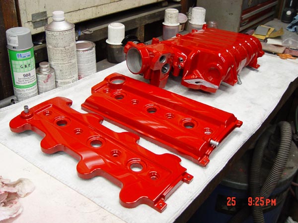
The Intake and Valve Covers are ready to be installed tomorrow.
The paint I used is Dimension III High Solid Acrylic Urethane Enamel. An acetone based etching primer was used to prep the aluminum. A little less than one pint of paint was used. I applied the paint with a 0.8 tip in my touch up gun at 70 psi to spray the paint. The paint was the easy part. The castings were extremely rough and took most of the effort to make them flat. I did'nt want shiny paint on a uneven and wavy surface. After about 200 hours of prep, paint and polishing, John has a show quality finish that he should be happy with.
More pics when installed.
------------------ Fred Bartemeyer Chairman Heartland Fieros http://www.heartlandfieros.com 86 GT 4spd 26k miles 87 GT 5spd. Blue 37k miles 88 Silver T-Top Formula 275,000 miles 87 GT 5 spd Annette's Sunshine Driver 88 GT 5 spd Annette's Daily Driver
IP: Logged
12:10 AM
Darth Fiero Member
Posts: 5922 From: Waterloo, Indiana Registered: Oct 2002
if someone were to send you the fiero wiring harness and the 3.4L DOHC wiring harness could you patch them together to make them work, then send it back? i can make minor changes in the wiring, but id have to pay someone to figure out the hard stuff, but when it comes to just making the wires longer or shorter, i can do that
im planning on a 3.4L DOHC in a 88 coupe with GT body and rear swaybar.
is the DOHC the easiest of the swaps wiring wise?
matthew
Matt, in my opinion, the 3.4 DOHC is probably the easiest all-around swap, especially when it comes to wiring. As far as if I can do a mail-order harness? Not at this time. I usually build all the harnesses to the specific car, therefore it is hard to do one outside of the car and make it look good once it is installed. However, if you need to know what wiring needed to be lengthend and shortened, basically everything was shortened except the MAP sensor wires. Since the 3.4 uses newer style sensors and DIS, you will also need to change the connector styles on much of the wiring. Best advice I can give to anyone is get the motor in the car, lay the wiring on it and see where things need to go. Try to keep the wiring clean and hidden. You should also have a complete harness for the 3.4 DOHC engine so you can get the connectors from it as well.
IP: Logged
12:21 AM
joshua riedl Member
Posts: 1426 From: watertown wi USA Registered: Jan 2004
i know this engine sits lower but for those using WFC mounts or similar i flipped the driverside harness upside down. you can see they are offset and flipping them allows a little extra room to get to the oil fill and dip stick. hopefully that saves someone else the time i wasted figuring that out.
IP: Logged
12:59 AM
86GT3.4DOHC Member
Posts: 10007 From: Marion Ohio Registered: Apr 2004
What I'm doing for my swap (If I ever get the engine, I was supposed to have it a month ago....) is to take an extra 2.8 harness, and the female 3.4 from the body of a lumina, and mate them into a big "y" shaped harness, that will allow me to simply plug the 3.4 into its plug, and then the two Fiero harnesses into the body. Seems ingeanous (LMAO, spelling) to me, I just hope it works, if so, I'll start making them for people. PLEASE tell me this should work PLEASE...... I hope I havent wasted all this time
IP: Logged
01:08 AM
Darth Fiero Member
Posts: 5922 From: Waterloo, Indiana Registered: Oct 2002
I don't know if your way will work but by all means try it if you think it is a good idea. As for the stock 2.8 harness, you only need to add 3 wires to it for the knock sensor, one egr solenoid (there are three in the digital egr), and the EVAP purge solenoid. Aside from that there are enough other wires in the harness.
IP: Logged
01:51 AM
ltlfrari Member
Posts: 5356 From: Wake Forest,NC,USA Registered: Jan 2002
Where is that MAP sensor hooked up to. I can see the two lines coming from the connector on the plenum. One goes to fuel press regulator, other would go to tranny modulator. Do you have the tranny modulator one hooked up to the MAP or is there another vacuum line somewhere you are connecting to?
Regarding wiring... When I removed the motor from the donor car(s) (both a 95 Grand Prix and 95 Monte Carlo) I was amazed how easy it was to pull the whole motor, transmission and wiring harness (with ECM and RS fuse panel) as one unit. Because, asside from some accessory connectors like water level sensor and A/C pressure switch and the battery, the firewall connector was the only other connection that had to be removed before the whole assembly could be dropped. That's what got me thinking about starting this motor outside the car before installation. When I removed the wiring harness from the 93, it included the RS electrical center which houses, among other things, the fuel pump relay. It appers that the RS electrical center gets its power from one of the wires hooked to the starter.
I've been pouring over the wiring diagrams to see exactly what has to be connected to just make the motor run and, so far, only a couple of wires are required:
Battery to starter and motor block.
From the bulkhead connector: PNK to ECM PPL and YEL Shorted to start (use momentary switch)
transmission connector: Jumper the ORG/BLK and the BLK/WHT wire to eliminate the neutral safty switch.
I'm still trying to figure out the fuel pump primer wire.
Except for some ALDL wires and instrument clustrer wires, that's it. The rest of the wires are for stuff I won't need.
Roy
IP: Logged
09:37 AM
Darth Fiero Member
Posts: 5922 From: Waterloo, Indiana Registered: Oct 2002
ltlfrari -- the MAP sensor is hooked into that vacuum manifold along side of the fuel pressure regulator. Since I am running a manual trans, I don't need the vacuum modulator to be hooked up. IF you are running an auto and need the vacuum modulator connected, you can tee the modulator in with the fuel pressure regulator no problem.
m0sh_man -- I am using the 3.4 TDC (16149396) ECM for this swap with a custom chip. The stock Fiero ECM is set up to work with a distributor so it is not directly compatible with the 3.4. I guess I could spend a ton of time redoing the Fiero chip to work but I think the 2 hours it will take me to wire in the 3.4 TDC ECM inside the car will be well worth it.
IP: Logged
02:27 PM
Darth Fiero Member
Posts: 5922 From: Waterloo, Indiana Registered: Oct 2002
Got the cooling system all hooked up today. Also Fred brought over the intake and cam covers and we installed them:
It doesn't look too bad doesn't it? One thing I noticed I am going to have to move the bulkhead connector pass-thru for the ECM wiring a little because it interferes with the oil fill cap. I was able to get the cap in and out of there but it is very tight and I don't want there to be any issues with the paint. What do you guys think of my custom engine side dog bone bracket?
Darth: would it be possible to get one more pic VERY similar to the last one there; a 'downward view' of the pulley end - hopefully showing the clearance and closeness to the frame? I am doing a frame mod to the 'intermediate' frame member and am concerned that it might interfere. I am calling the horizontal frame member that is immediately above the cradle 'the intermediate' piece. Thanks if you can manage!! gp
IP: Logged
10:51 PM
Darth Fiero Member
Posts: 5922 From: Waterloo, Indiana Registered: Oct 2002
Darth: would it be possible to get one more pic VERY similar to the last one there; a 'downward view' of the pulley end - hopefully showing the clearance and closeness to the frame? I am doing a frame mod to the 'intermediate' frame member and am concerned that it might interfere. I am calling the horizontal frame member that is immediately above the cradle 'the intermediate' piece. Thanks if you can manage!! gp
yea, I will go back out to the garage here in a few mins and get those for you.
Ok, snapped off a few more pictures. Here is the picture of the pulley side showing frame clearance, there is actually quite a lot.
The only problem I had clearance wise was between the rear timing belt cover and reiforcement bracket that ties in the strut tower to the dog bone bracket that is welded to the car. All I had to do was cut off a slight amount from the bottom of the bracket. As for the front, well it was pretty much self explainatory.
Check out the custom dog-bone bracket I made from welded 1/4" steel plate. It connects to the stock engine lift bracket using two bolts and existing bolt holes.
Here is view from the other side of the car:
Notice the rear of the dog bone had to be moved up and back a little bit. I had to do this so the dog bone would not hit the vacuum manifold on the intake.
[This message has been edited by Darth Fiero (edited 05-26-2004).]
Darth: MUCHAS gracias for that pic - I saw another that seemed to show almost no room from the front pulleys to that frame member and figured I was toast for my engine swap (after doing some frame mods that decreased the clearance) - but I am sure I am OK now. I suspect the other (trans/clutch) end is equal or better for clearance so I am fine.
Super and thanks again. I had chased a few guys to try to get exactly that. As the saying goes: "when you want to get something done, give the job to a busy man".........! it's true. gp
IP: Logged
11:16 PM
May 27th, 2004
gascarracer Member
Posts: 129 From: Batavia, Ohio, USA Registered: Apr 2003
is there any other place to put the oil fill? and would this be more of a problem if not mounted lower like you did?
There is NO other place to put the oil fill. The only other way to do this is to "machine" another oil fill hole in the valve cover elsewhere. Now if the engine was sitting higher, yes it would be a bigger problem. My solution looks simple on paper and I will try it out probably tomorrow. I will document how it goes with pictures so you can see just how easy it turns out.
I did one other 3.4L/5-speed Fiero swap a couple of years ago and ran into a similar problem EXCEPT I didn't use custom mounts. I used stock mounts on that Fiero and a shorter dog-bone which tilted the engine back a little which allowed easier access to the oil filler cap. Fred seems to think the 89 Prototype Fiero had the engine tilted back in it slightly because the intake plenum looked more level (front to back) in the engine compartment.
Concerning this swap, the bottom oil pan plane is level with the cradle, front to back and left to right so the engine is in there square. The oil cap problem is a minor glitch that will be solved easily enough, I hope.
IP: Logged
03:14 AM
gascarracer Member
Posts: 129 From: Batavia, Ohio, USA Registered: Apr 2003
Darth; looking superb. A professional install and a professional attitude too. Very commendable and welcome. No 'attitude' or 'flaming' or 'put-downs' etc; just attention to every detail, accurate documentation and cooperation; what a tremendous combo. My hat is off to you. (woops! sorry for the glare! ......) re: the lowered mounts - if and when you get a chance (and I expect it will be 'down the road' a bit....) could you get a pic or a measurement or something regarding axle shaft-to-cradle (frame) clearance? I guess the critical issue is when the suspension is hanging free. I doubt there is any issue at all about upward axle movement, of course. I am interested in getting the C of G (engine/trans) as low as possible and that item is of course key. I am sure this might also be of interest to all engine swappers to get a good idea of what the parameters are for overall clearances.
any guesses as to how much lower this combo is sitting from .......where it would be otherwise? Fantastic thread; thanks!!!
IP: Logged
07:57 AM
ltlfrari Member
Posts: 5356 From: Wake Forest,NC,USA Registered: Jan 2002
ltlfrari -- the MAP sensor is hooked into that vacuum manifold along side of the fuel pressure regulator. Since I am running a manual trans, I don't need the vacuum modulator to be hooked up. IF you are running an auto and need the vacuum modulator connected, you can tee the modulator in with the fuel pressure regulator no problem.
Are you saying there's a seperate vacuum hookup under there as well as the one to the fuel pressure regulator. I knolw the tranny modulator line went THRU there to the tranny since I removed mine but the only other vac line/point I know of is the fuel pressure regulator. I have not taken the plenum off yet so I am not exactly sure what is under there vacum connector wise. At the mo I have mine off the tranny modulator connection on the plenum (same place as the fuel pressure regualtor hook up to).
would tilting the engine to make the intake level hurt anything? even tho that would probably be a pain in the ass to do...
are you going to make the front engine mount available or are we going to have to come up with our own? (i believe we can already purchase getrag lowering mounts...)
thanks for your reply! + for you if i havnt already given one!
------------------ Brandon Edmonds
1996 Taurus SHO (my baby) 1986 Ford EXP (rust galore, but im keepin it!) 1986 Fiero (to be my street rocket) 1977 yamaha xs750-2D (in pieces right now, will be done for summer!)
IP: Logged
11:11 AM
Darth Fiero Member
Posts: 5922 From: Waterloo, Indiana Registered: Oct 2002
ltlfrari -- there is no additional vaccum port under the intake. However, you can use a vacuum T fitting to split off the vacuum line that goes to the fuel pressure regulator so you have a place to plug in the modulator. Yes, this will require you cutting the metal vacuum modulator line.
joshua -- flipping the plug is an idea and I will look into it. However if it does not give me the amount of clearance I want I may still have to move it. I will consider both flipping it and moving it a little less if I can get away with that.
flyguyeddy -- tilting the engine will not hurt anything other than giving you clearance issues. I have no plans on doing a front engine mount but will get you some detailed pictures so you can make your own.
Rare W66 I have to say that the paint job is awesome and guys, the pics don't do it justice! yellowartero is going to have a heck of a time getting the body to look as good as the engine compartment, but I know the kind of work he does when it is a labor of love and I am confident that this will be no ordinary grocery getter which I think is what he ordered from Darth. So anyway Darth, how long before this thing is ready for a test drive? I'm ready!!!
Beautifious Darth, thanks for being the 'sharing sort' I'm learning a lot again thank-you
quote
Originally posted by Darth Fiero:
-- 1) tilting the engine will not hurt anything other than giving you clearance issues. 2) I have no plans on doing a front engine mount but will get you some detailed pictures so you can make your own.
1) Good news. 2) Very good news. And also drawings of the dog-bone mounts? Possibly some thoughts on thickness and taper for the shims to rotate the motor/tranny back on the cradle.
Norm
IP: Logged
08:52 PM
Darth Fiero Member
Posts: 5922 From: Waterloo, Indiana Registered: Oct 2002
Joshua, thanks for the idea about fipping the bulkhead connector, I did just that and moved it up.
Here is how much you need to cut:
Once you get it cut out you will need to add a piece of sheet metal to cover up the space left after moving the connector up. I used black RTV to glue the piece of metal in place as well as seal the metal and connector.
So that is about as far as I got today, aside from routing the crankcase vent lines. I have to go out of town for the weekend so this project will be put on hold until next week.