Originally posted by Honest Don: At what increment are you advancing timing?
For initial setup, I got the car running with a boost retard of 0.3 °/kPa, relative to the values I have in the 100 kPa row. It worked, and when my wastegate wasn't working right, I overboosted to 200 kPa a few times without issue.
I realized with that much slope, I wouldn't have any advance left in the higher boost regions. So I reduced the slope to 0.2 °/kPa. I drove around like that until this week (on wastegate spring pressure, about 150 kPa).
Last weekend when I raised the manifold pressure to 175 kPa, I noticed (on the butt dyno) that the engine seemed to fall flat on its face, despite 25 kPa more pressure. I concluded that the boost retard was excessive, and I reduced it to 0.12 °/kPa (as in the table pictured above). The car feels much better like this. Since the car feels good like this now, I'm going to leave the ignition timing the way it is.
I will drive around at 175 kPa on the current tune for at least a month or so to make sure everything is OK at this boost level.
If all goes well, then I will look into increasing the manifold pressure to 200 kPa (with water injection). At that point I may decide if I still like the ignition timing table or not.
I am not advancing the timing until the onset of knock, then backing off. Since I have low compression (and water injection), I suppose that I can set the timing to MBT, rather than being knock-limited. Overadvancing the timing beyond MBT to the knock limit would be counterproductive. This engine really does not exhibit any tendency to knock.
Once I get the tune roughed in as good as I can get it by street/dragstrip/estimation methods, then I may book some time on my local tuning shop's Dynapack dyno. This would allow me to more precisely find the MBT (if not knock-limited) spark advance in the high boost region.
quote
Originally posted by Honest Don: Results?
quote
Originally posted by Franked: So.. I am not going to be the only one to ask, what was your 1/4 mile time?
I didn't beat that time on 175 kPa last Saturday due to: 1. I simply cranked up the boost (earlier the same day) without really adjusting the tune. 2. I wasn't feeling sharp that day. I had a run where I missed a shift, and another where I launched with massive wheelspin. I decided to stop, and enjoy watching other people race.
[This message has been edited by pmbrunelle (edited 08-13-2020).]
Unsurprisingly, my sketchy water injection system failed. Eric called this one!
It's been more than a year since the initial setup, so I figured that the stagnant water might corrode things enough to cause problems.
Therefore, before cranking up the boost further, I wanted to make sure that the system was functional. I didn't trust it...
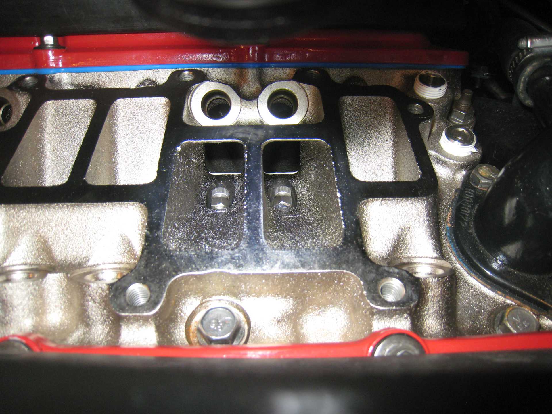
I removed the upper and middle intakes; this gave me a view of the intake runners and the water nozzles:
Then, my plan was to turn on the water; long enough to observe the water spray, without flooding the engine with water.
Well, the nozzles just dribbled a small amount of water. Good thing I decided to check up on things before increasing the boost.
I then removed the lower intake, and the nozzles.
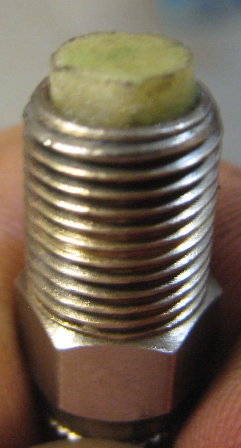
Here is a view of one of the nozzles:
The (previously) white object is a plastic foam filter that is pushed in the inlet hole of the nozzle.
It seems like green bacterial slime grew on the filters (all six), blocking the filters.
I then reinstalled the same nozzles into the intake, but with the filters removed, and they sprayed like usual. Problem identified!
I think I'll be reassembling the engine without the filters on the nozzles, since the bacterial blockage could return if I reinstall new filters. They seem to like this plastic.
[This message has been edited by pmbrunelle (edited 08-17-2020).]
Unsurprisingly, my sketchy water injection system failed. Eric called this one!
It's been more than a year since the initial setup, so I figured that the stagnant water might corrode things enough to cause problems.
Therefore, before cranking up the boost further, I wanted to make sure that the system was functional. I didn't trust it...
I removed the upper and middle intakes; this gave me a view of the intake runners and the water nozzles:
Then, my plan was to turn on the water; long enough to observe the water spray, without flooding the engine with water.
Well, the nozzles just dribbled a small amount of water. Good thing I decided to check up on things before increasing the boost.
I then removed the lower intake, and the nozzles.
Here is a view of one of the nozzles:
The (previously) white object is a plastic foam filter that is pushed in the inlet hole of the nozzle.
It seems like green bacterial slime grew on the filters (all six), blocking the filters.
I then reinstalled the same nozzles into the intake, but with the filters removed, and they sprayed like usual. Problem identified!
I think I'll be reassembling the engine without the filters on the nozzles, since the bacterial blockage could return if I reinstall new filters. They seem to like this plastic.
You're not just going to convert the nozzles to a "Sneaky Pete" direct port Nitrous system?
[This message has been edited by Will (edited 08-20-2020).]
I think someone's done something like that at some point, but I don't recall specifics. Unfortunately, the idle air distribution passages are probably terrible for cylinder-by-cylinder wet flow distribution.
Originally posted by pmbrunelle: Now the injectors are really maxed out (94% duty cycle observed).
With the Green Giant injectors, peak duty cycle is now 61%.
Good, there's now plenty of headroom to increase the boost further!
...except for:
quote
Originally posted by fierosound: If the RAM clutch fails, consider Canadian made Bully Clutch. I have the same one in both my cars. 2 others here in Calgary have also bought them. (one is 3800 S/C, the other a 3400/Turbo)
When I go WOT in 4th gear, as the engine hits its torque peak of ~3500 RPM, the RAM 9.75" HD clutch slips. The hot summer days are largely behind us here, so I think that the cooler air helped the engine produce more torque.
Tony, do any of your Fiero friends with this clutch have a Muncie like me, or do they all have Getrags? I'm wondering if this clutch can work with my transmission. Bully doesn't seem to list any Muncie 4-speed applications on their website.
Also if anyone else has an opinion regarding Muncie/Getrag clutch interchangeability, feel free to chime in. Or simply a recommendation for a Muncie.
[This message has been edited by pmbrunelle (edited 08-23-2020).]
Originally posted by Will: The pressure plate, disk and flywheel are the same. The throw out bearing is different.
Do you know why Spec (as an example) lists different part numbers for the 4-speed vs. 5-speed? I guess I could ask them.
I was also wondering if the clutch release fingers are at the same distance from the flywheel regardless of 4-speed vs. 5-speed.
The throw-out bearing is on my transmission, so I expect to keep that.
quote
Originally posted by Will: Interested in a dual disk 7.25"?
I'm not really sure what that involves. If I sift through your build thread "The Mule rides again (sort of) - pics." will I find information on that?
This is my wishlist of minimum specifications: 410 lb*ft engine torque 50000 km lifespan Ability to slip the clutch for stop+go traffic Moment of inertia not critical; shift time (well, synchronization) is slow with my current setup, but I accept that.
I don't know if there exists a solution that satisfies the above wishlist; I have some research to do.
Do you know why Spec (as an example) lists different part numbers for the 4-speed vs. 5-speed? I guess I could ask them.
I was also wondering if the clutch release fingers are at the same distance from the flywheel regardless of 4-speed vs. 5-speed.
The throw-out bearing is on my transmission, so I expect to keep that.
The clutch supplier has to box the pressure plate, disk and throw out bearing in the same package, so they need a different BOM for a package going for the Muncie vice Getrag vice Isuzu.
quote
Originally posted by pmbrunelle:
I'm not really sure what that involves. If I sift through your build thread "The Mule rides again (sort of) - pics." will I find information on that?
This is my wishlist of minimum specifications: 410 lb*ft engine torque 50000 km lifespan Ability to slip the clutch for stop+go traffic Moment of inertia not critical; shift time (well, synchronization) is slow with my current setup, but I accept that.
I don't know if there exists a solution that satisfies the above wishlist; I have some research to do.
Torque capacity with a dual disk is easy. Most 7.25" MFG's have multiple springs to tailor clamp load, and of course a dual disk clutch has twice the capacity of a single disk.
I'm working on the fitment, so I have no idea what the service life would be... which is STRONGLY dependent on usage characteristics anyway. A couple of members here have done dual disk clutches, and I've asked elsewhere. What I've gleaned is that with organic disks they work in traffic, although still not as friendly as a production style clutch. QuarterMaster has a part number (probably hasn't made any for a long time) for a bolt-in flywheel for the V6 (Well... SD4). I even have one. I had to build one from scratch for the Northstar.
There's a good aftermarket built around the 7.25" racing clutch "architecture". All the MFG's recognize that it's in their best interest to make sure that another MFG's customer can bolt in one of their clutches. Thus they all use the same mounting bolt circle and locating journal diameter.
Stack heights and setup heights vary considerably depending on configuration. Configurations can vary from two 0.100" sintered iron disks to two 0.200" cerametallic or organic disks to two 0.250" cerametallic or organic disks. A clutch with two 0.250" disks will just *BARELY* fit in the 282 bellhousing. The Muncie has a slightly deeper limiting depth in the bellhousing, so the same configuration should fit there.
There are no Muncie, Isuzu or Getrag-specific throw out bearing holders. (QM might have one for the Muncie, but I don't know the PN; haven't looked either) This is Tilton's TOB for their clutches: https://www.summitracing.com/parts/til-62-002-5 Clearly it needs a holder, which needs to be specific to the transmission. The top of the pressure plate cover is the tallest part of the clutch, with the diaphragm spring fingers "below" that. The holders end up being fairly tall as a consequence.
Once it fits mechanically, the next issue is that the 7.25" clutches have a short throw with a high throw out load. That's a throw in the range of 0.250" to 0.300" with a load as high as 500#. The production clutches have throws more like 0.500-0.625" and loads in the 250-300# range. Setting the entire 7" of Fiero pedal travel to reduce to a 0.300" throw results in a 22# pedal load on a 500# throw out load. That's actually quite light, but requires just the right system in between the pedal and the clutch.
Since all of the Fiero throw out systems (Muncie, Isuzu, Getrag, F23, F40) are designed for a fairly consistent set of throw & load characteristics, the adaptation method that comes to mind for me which should be applicable to all is a hydraulic ratio divider. That would be a hydraulic device in which the master cylinder pushes fluid into a large diameter piston which mechanically pushes on a small diameter piston, which pushes fluid to the slave cylinder (or are "leader cylinder" and "follower cylinder" now the politically correct terminology?). I think one hydraulic divider design could accommodate all 5 of the configurations I listed above, but I haven't collected enough data from the various systems to make sure that I select a ratio that hits the "sweet spot" that covers all five.
[This message has been edited by Will (edited 08-24-2020).]
Originally posted by Will: The clutch supplier has to box the pressure plate, disk and throw out bearing in the same package, so they need a different BOM for a package going for the Muncie vice Getrag vice Isuzu.
Nevertheless, it is still interesting to discuss the 7.25" clutches.
Is there a reason that the throwout bearing/release mechanism native to each transmission cannot release the 7.25" clutch? Packaging problem because the fingers are too sunken in, and therefore difficult to reach? Do you think that the hydraulic pressure needed to release a 7.25" clutch would damage a factory HTOB? On an external-slave transmission, do you think the fork could be damaged from excessive force?
For the external-slave transmissions, at first glance, either a longer release lever, or a bigger-bore slave would seem to be less kludgy solutions than a stepped piston deal.
The throw out bearing holders for the OE style clutches don't put the throw out bearing in the right location/depth for the 7.25" clutches. Thus each transmission needs either a holder specific to its mechanical release mechanism or a modification to the HTOB. I haven't looked at the Muncie fork specifically, but the Getrag fork seems to be fine with the extra load in the few cases that have gone to dual disk clutches. It's less than double the original load. If I can package it, I'll include ball bearing trunions on the holder(s) to eliminate sliding contact and the resultant wear.
Higher pressures in the HTOB shouldn't be a problem... after all, brake calipers handle MUCH higher pressures than the clutch hydraulics see. Seals should be similar between the two.
For one external slave transmission, I'd build a bigger slave and call it done. For three with different slaves, different arms and different brackets that solution is more work. For FIVE choices with two being less practical for making a slave, the hydraulic divider is the only option I see that covers all five with one solution.
[This message has been edited by Will (edited 08-25-2020).]
I worked on the tuning the X-Tau model this past week, whereby the ECU multiplies the fuel injection quantity by the inverse of the fuel puddle's low-pass transfer function. It is an attempt to cancel the fuel delivery lag effect of the fuel puddle in software.
In practice, perfect cancellation is not possible. I initially tried X-Tau with "ideal" coefficients, but they resulted in too much noise/variation in fuel delivery. The resulting torque variation was objectionable when cruising at constant speed. Perfect cancellation of the fuel puddle would require the ECU's X-Tau transfer function to have very high gain as frequency increases; not necessarily practical. Depends on the noise of your sensors I guess.
My dad helped with this; he drove the car while applying throttle steps at different RPMs. I was recording things with the laptop and adjusting stuff.
I did achieve partial puddle compensation with X-Tau; good enough that TPS-based accel enrichment is not necessary with the engine warmed-up. The throttle response was still a bit more snappy with TPS-based accel enrichment, so I kept it, but at a reduced level. I still rely heavily on TPS-based accel enrichment following a cold start.
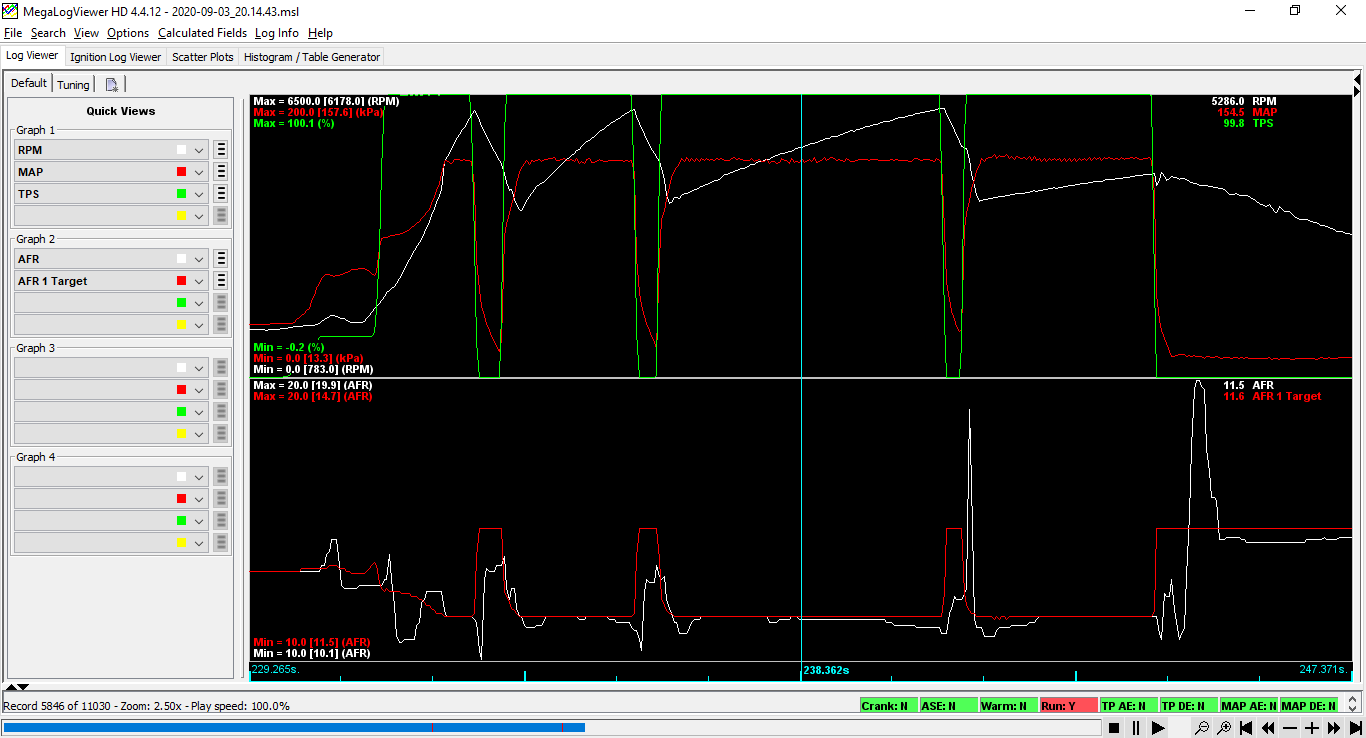
Overall I am happy with how the AFR tracks the AFR target now. Here is a 1-2-3-4 WOT run:
There is a lean spike on the 3-4 shift, but it wasn't perceptible on the butt dyno, so I'm fine with that. I believe that this fast short spike can happen when the throttle opens fast, between the injection quantity calculation, and the intake valve swallowing air.
During gearchanges, I don't manage to bring back the AFR to stoich; that's OK, it doesn't cause a driveability problem, just pollution.
We can see why (among other reasons) cars have moved to drive-by-wire, but (as a consumer) I prefer the paradigm where the driver is the master of his car, and the ECU must accept and cope with the situation it's been put into.
I don't know if MegaSquirt is able to extend an in-progress squirt, or if once it's been started, the duration is fixed.
1st gear WOT suffered from a leaner AFR than in other gears. At first, I blamed the fuel delivery delay (during hard acceleration) due to the fuel puddles. I then found that software filtering of RPM and MAP signals were largely responsible for making the fuel delivery lag behind the engine's fuel needs. So I reduced the amount of RPM/MAP filtering, and things are better in 1st gear now.
With La Fiera's injectors, I haven't noticed much different in how the engine runs hot, at the present boost level.
The biggest improvement was in cranking and starting the engine.
With the Accel injectors, I had a hard time to inject the correct amount of fuel when cranking. It was not easy to find the happy medium between flooding the engine, vs. firing up quickly.
With the Green Giant injectors, the tuning window was wider; I converged on a suitable cranking fuel quantity quickly. I suppose that they make a better quality mixture.
[This message has been edited by pmbrunelle (edited 09-04-2020).]
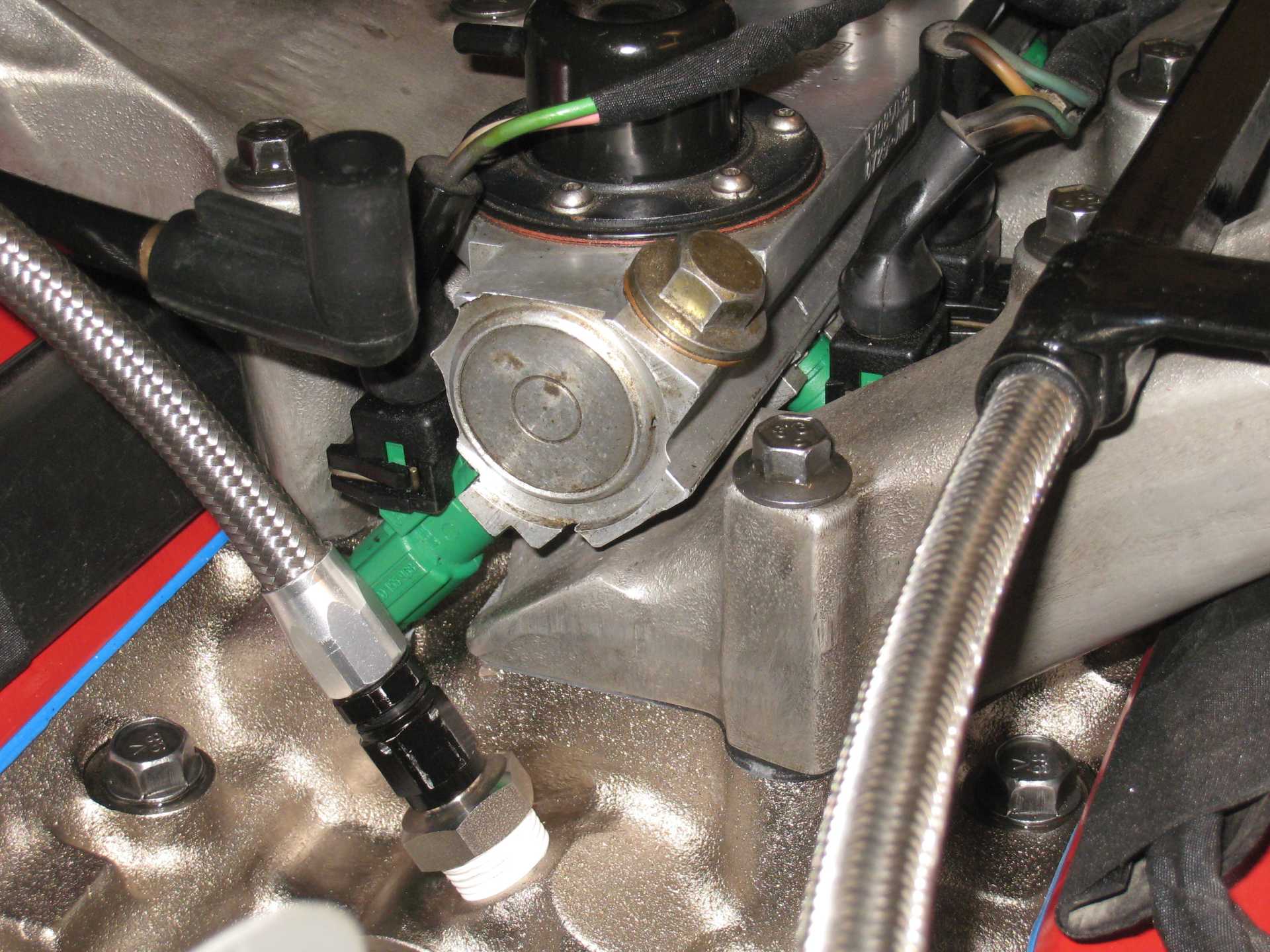
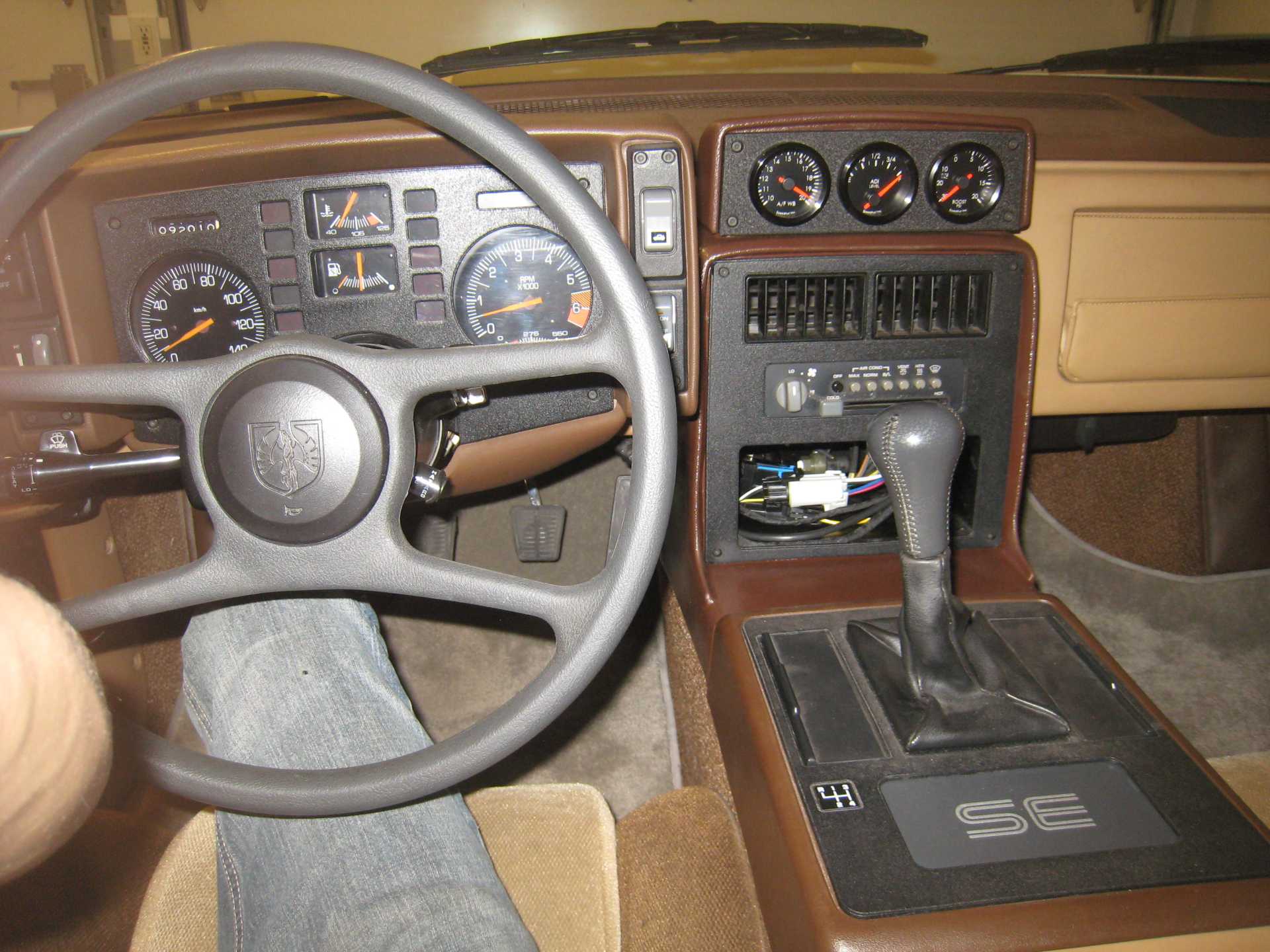
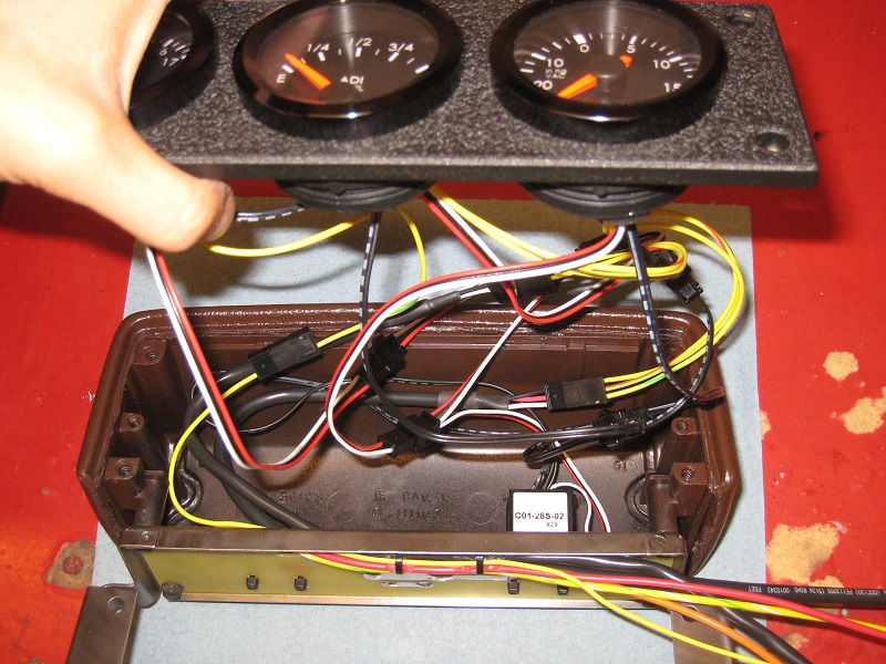
I installed three Speedhut gauges in the aux gauge pod. I used one of the 3-hole aluminium mounting plates available on ebay. I primed it with yellow zinc chromate, and then topped it with black VHT wrinkle paint.
AFR ADI Level (i.e. the amount of juice in the Anti-Detonant Injection tank) Boost
Since I have an 85 V6, the oil pressure is already combined into the factory tach.
The Speedhut gauges are quite shallow, and thus good for mounting in situations with low clearance behind the mounting panel, such as the aux gauge pod.
I am not super-happy with having the gauges on the aux gauge pod like that. They're a bit hard to see from the driver's position.
I could always build a replacement mounting plate with angled mounting surfaces, to orient the gauges more towards the driver. However, I feel that alienates the passenger, and I want to be able to see the gauges when I'm the passenger/tuner.
So they will remain on the flat panel for now, in the compromise position.
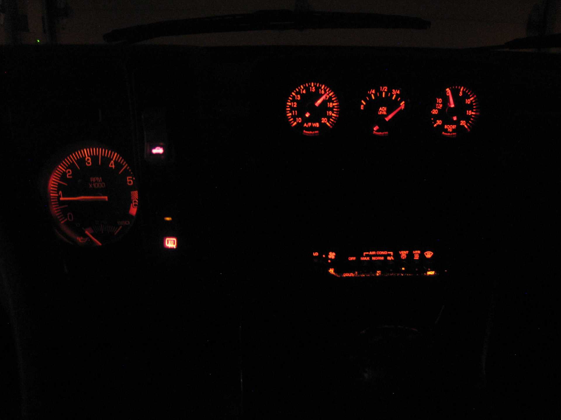
Illumination of Speedhut gauges is somewhat underdeveloped. According to Speedhut, the LED needles aren't dimmable, and the electroluminescent faces are only dimmable via a potentiometer on an external inverter box: https://www.speedhut.com/ec...e-Gauges-with-Dimmer
I was able to make the EL inverter box work like stock by cutting off its pot, and varying its input voltage by powering it from the Fiero dimmer. I installed a series diode to drop the voltage some 0.6 V.
For the LEDs, I installed a 2.2 kOhm resistor in series with the LED supply wire (for three gauges), and then connected that to the Fiero dimmer.
Now the Speedhut gauge lighting matches that of the Fiero gauges, even as I use the Fiero dimmer to vary the gauge brightness. Still, I shouldn't have had to add external parts, plus finding a place to mount the external inverter box took some head-scratching.
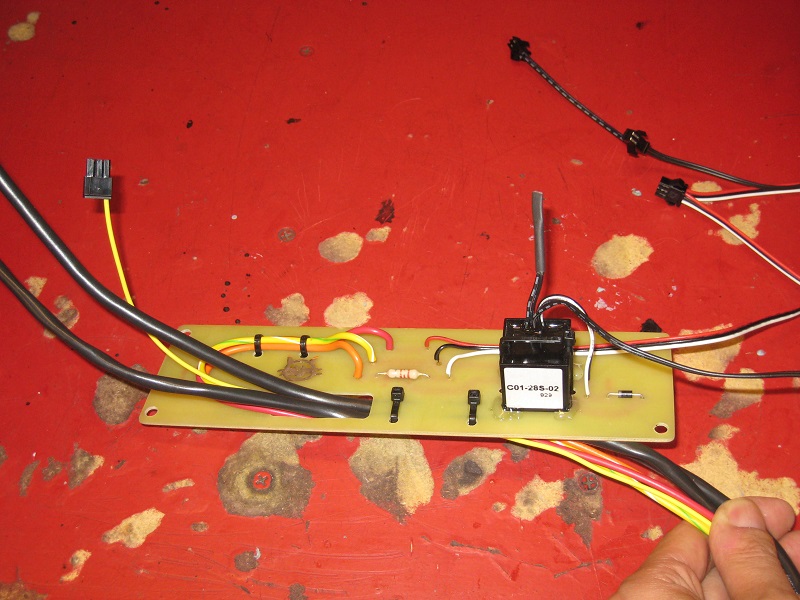
Adding external parts (single resistor, diode) is one of the harder mods to do on a car, since you can't just leave these things loose in the harness, subject to the leads flexing. If you really just have one part to add to a harness, I was thinking of using an inline ATO fuseholder. Two spade terminals could be soldered to the component, and the assembly could be plugged into the fuseholder.
I ended up making a board to support the loose parts, and to provide strain relief for the wires. The board goes installs underneath the stock gauge pod, sandwiched below the stock screw heads.
Originally posted by pmbrunelle: *******************************************************************************
With La Fiera's injectors, I haven't noticed much different in how the engine runs hot, at the present boost level.
The biggest improvement was in cranking and starting the engine.
With the Accel injectors, I had a hard time to inject the correct amount of fuel when cranking. It was not easy to find the happy medium between flooding the engine, vs. firing up quickly.
With the Green Giant injectors, the tuning window was wider; I converged on a suitable cranking fuel quantity quickly. I suppose that they make a better quality mixture.
That is because despite being bigger, they atomize the fuel better thus improving combustion. Glad you are taking advantage of them!
Originally posted by Will: The latent heat of vaporization of water is considerable... you can still get good charge cooling from vaporizing hot water. Just don't displace too much air with water vapor at crappy flowing intake ports.
Well, I did water injection tests for the first time on Tuesday.
Keeping manifold pressure constant (MAP of 160 kPa), I wanted to study the effect of water injection on engine torque.
If the water spray displaces air, then less air will enter the cylinder, and torque will be reduced. I suppose that water could reduce torque by some other mechanism as well.
To estimate engine torque, I datalogged WOT pulls in 2nd gear from idle to the rev limiter (6200 RPM). I then looked at how long it look for the engine to go from 4000 RPM to 6000 RPM. I did all the pulls on the same section of road, all within one hour.
I did three types of test: 1. Water injection off 2. Simple on/off control, activation above 2375 RPM and 137.5 kPa MAP. Estimated water/fuel ratio (WFR) of 0.33 at redline, 0.54 at 2500 RPM. 3. Water solenoid is pulsed like a fuel injector (firing once per cam revolution). WFR is more constant, ranging from 0.26 at redline, and 0.34 at 3000 RPM.
code:
Test #	ADI Status	Time (s)
1	Off		1.61
2	Simple on/off	1.62
3	Pulsed		1.60
4	Off		1.58
5	Simple on/off	1.82
6	Pulsed		1.60
7	Off		1.58
8	Simple on/off	1.59
9	Pulsed		1.57
If the engine is not over-watered (i.e. the WFR is within a reasonable range), I conclude that water injection does not reduce engine torque.
Test #5 is an anomaly. I think the engine was overwatered; in that instance, the engine was struggling to idle after the pull. I suspect that I began the pull with the engine in an already "drowned in water" state.
When driving at low speed/load, if the water injection is activated, then you feel the engine stumble and reduce torque output. It is possible to stall the engine in this way. Too much water can make restarting difficult, and it can take a while (like one minute of driving) to clear the excess water.
If I tune the setup to only spray during high boost WOT when necessary, I don't think there will be any unwanted side effects (oil contamination, stalling).
[This message has been edited by pmbrunelle (edited 10-22-2020).]
Well, I did water injection tests for the first time on Tuesday.
Keeping manifold pressure constant (MAP of 160 kPa), I wanted to study the effect of water injection on engine torque.
If the water spray displaces air, then less air will enter the cylinder, and torque will be reduced. I suppose that water could reduce torque by some other mechanism as well.
To estimate engine torque, I datalogged WOT pulls in 2nd gear from idle to the rev limiter (6200 RPM). I then looked at how long it look for the engine to go from 4000 RPM to 6000 RPM. I did all the pulls on the same section of road, all within one hour.
I did three types of test: 1. Water injection off 2. Simple on/off control, activation above 2375 RPM and 137.5 kPa MAP. Estimated water/fuel ratio (WFR) of 0.33 at redline, 0.54 at 2500 RPM. 3. Water solenoid is pulsed like a fuel injector (firing once per cam revolution). WFR is more constant, ranging from 0.26 at redline, and 0.34 at 3000 RPM.
code:
Test #	ADI Status	Time (s)
1	Off		1.61
2	Simple on/off	1.62
3	Pulsed		1.60
4	Off		1.58
5	Simple on/off	1.82
6	Pulsed		1.60
7	Off		1.58
8	Simple on/off	1.59
9	Pulsed		1.57
If the engine is not over-watered (i.e. the WFR is within a reasonable range), I conclude that water injection does not reduce engine torque.
Test #5 is an anomaly. I think the engine was overwatered; in that instance, the engine was struggling to idle after the pull. I suspect that I began the pull with the engine in an a the already "drowned in water" state.
When driving at low speed/load, if the water injection is activated, then you feel the engine stumble and reduce torque output. It is possible to stall the engine in this way. Too much water can make restarting difficult, and it can take a while (like one minute of driving) to clear the excess water.
If I tune the setup to only spray during high boost WOT when necessary, I don't think there will be any unwanted side effects (oil contamination, stalling).
Back in 2003-2005 I had a Dodge Spirit Turbo SOHC 2.5L and I experimented with water injection because it didn't mater what type of race fuel I used, the engine knocked bad. I had different set ups for the location of the water nozzles. In my testing concluded that the further away from the TB I placed the nozzles, the more timing I could add and the more power, specially torque the engine developed. I started with 250WHP (knocking) and 275WTQ and when I was satisfied with the power and torque for road racing not peak power, I ended with 420WHP and 477WTQ. What I learned was that the more atomized the water/meth the better and smoother the power delivery was and to do that I increased the pump's water psi to max and went down a bit on nozzle's flow. By forcing more water pressure through the smaller nozzles, the mist was also much cooler. The result was a super atomized fog-like cooler mist. It was so atomized and foggy that when I tested it outside the pipe the mix would take a long time to fall to the ground. Also the nozzle placement was paramount. The best results I had was installing 2 nozzles in series. The smaller of the 2 was installed right after the turbo, about 32 inches away from the TB. And the larger nozzle 2 inches before the TB to get rid of the heat that 1st nozzle couldn't absorbed. I was also running on the leaner side, no need to enrichen for charge cooling. It was a simple on/off system that was triggered at 15psi manifold pressure. The use of the lower plenum's cold start passages to install the nozzles is a very clever approach but I believe you can get better results if the nozzles are place further away from the combustion chambers giving the water/meth more time to absorb the heat out of the incoming air.
[This message has been edited by La fiera (edited 10-23-2020).]
Since the water injection system is a bit tricky to install after the fact, I decided to do it in advance, to be prepared when knock occurs. Pressure now is 90 psi across the water nozzles.
Eventually, as I increase the boost, I might reach the knock limit. That's when I will see if the port water injection is effective, or if I should change things.
I still have stock heads, including casting flash in the ports, so that limits cylinder filling. If I decide to port the heads, that also might get me to the knock limit (if boost alone doesn't get me there).
I know about your Dodge, I saw the build thread! What kind of WFR were you running on the Dodge?
Originally posted by pmbrunelle: What kind of WFR were you running on the Dodge?
I had no idea of the ratio. I just set it up where I could run 30psi of boost with an extra 7 to 10 degrees of ignition timing without knock. The sweet spot was right at1650F EGT, before or after that the engine dropped power.
Water injection tests will have to continue next year!
As winter approaches, there is too much risk of the water freezing in the system and breaking things.
I drained the tank, and refilled it with a 50-50 mix of antifreeze-water. I ran the pump to circulate the 50-50 mix throughout the system.
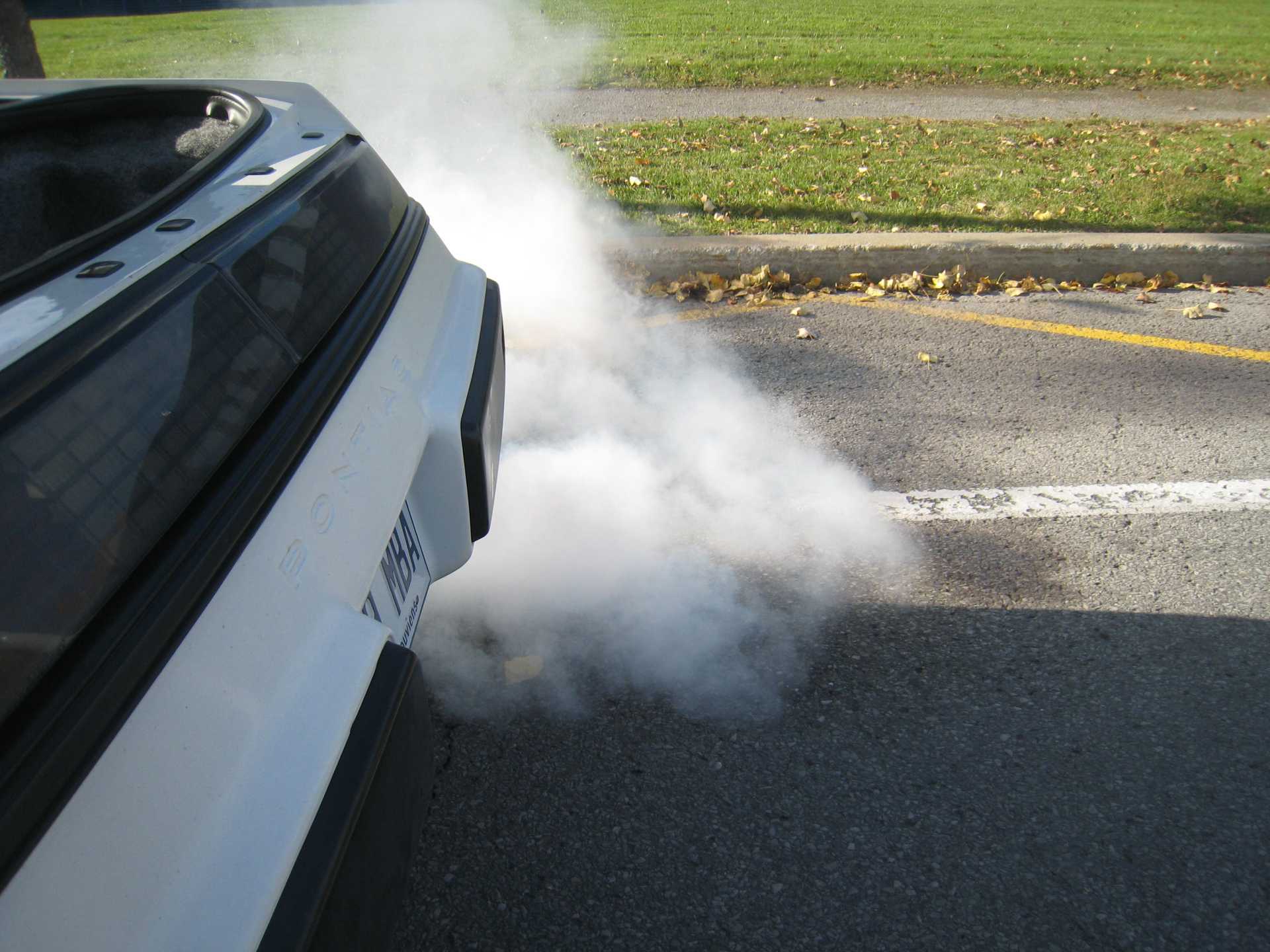
There was some pure water that was trapped in the intake and nozzles. I decided to turn on the water injection until the antifreeze-water replaced the pure water in the nozzles.
Once there was the white antifreeze smoke coming out the exhaust pipe, I knew that the water injection system had no more pure water in it.
NOT a head gasket leak!
[This message has been edited by pmbrunelle (edited 10-27-2020).]
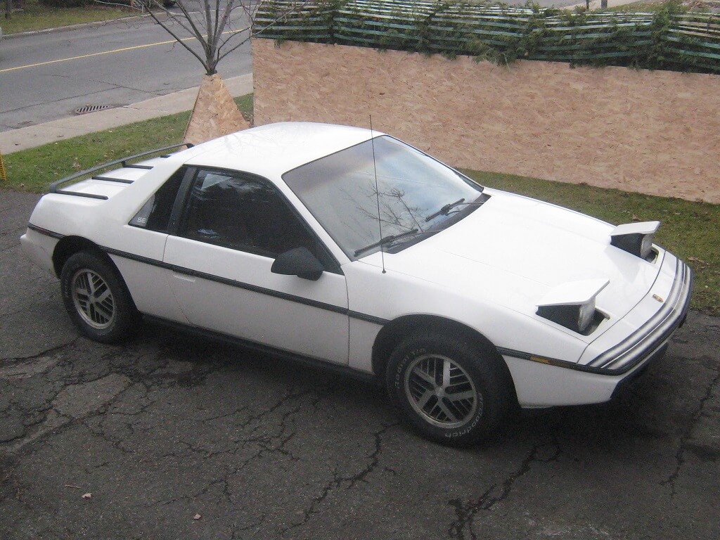
I purchased this Fiero in December 2016. A mostly bone-stock 1985 SE, with 53k miles. Minimal rust and fairly decent paint; should look good enough (by my standard) with a wash and wax, and some minor fixes (dew wipes, headliner, that sort of thing). It came with the automatic transmission, but that's fine; transmissions can be changed.
Half an hour into the 2 hour drive home, the 2.8 started knocking; the car had to be towed.
The engine's death signaled to me: PROJECT TIME! Time to do the turbo project I've always wanted for a Fiero, get rid of the slushbox, and fix the "incidentals" while I'm at it.
Now that I've been working on the car a little while, I guess it's a good time to make a project thread.
1. Very cool thread - nice attention to detail.
2. 2.8 knocking.....That is th 79th time I have heard of the stock 2.8 motors having bearings go bad... Why are they so vulnerable?
[This message has been edited by DimeMachine (edited 10-27-2020).]
It seems that the Fiero 2.8 (pre-88 at least) rod bearings aren't well-oiled.
For instance, the 2.8 has two pressurized oil galleries up top that supply the lifters and cam bearings. Then, oil from the top end goes down to each main bearing. When the cam bearings wear out, they leak more oil, and less oil makes it to the bottom end. Some engines have another oil gallery dedicated to supplying the mains with oil.
Once oil does eventually get to a main bearing journal, the oil then has to flow through a drilled hole in the crankshaft to get to the rod bearing. On the Fiero 2.8, from what I remember, the main bearings are smooth, having a simple round hole where pressurized oil enters the bearing. On the later model main bearings, there is a circumferential groove to allow a high flow of pressurized oil to feed directly into the drilled hole on the crankshaft as it rotates, so the Fiero 2.8 is less good in that respect.
Those with original 2.8s may want to replace the cam bearings as a preventative measure. I haven't paid serious attention to see if later-model main bearings can drop into the Fiero 2.8.
On the White Bug I have grooved main bearings, and I had the local engine machine shop replace the cam bearings.
[This message has been edited by pmbrunelle (edited 10-27-2020).]
I'm thinking about brake modifications. One idea I have is to use 88 calipers at all four corners, with bigger discs.
With the 84-87 Fiero, the parking brake cables are typically routed below the CV joints.
With 88 rear calipers oriented with the cable entry at the bottom, the bleeders end up below. Not a good situation.
Looking at the 88 rear caliper castings (in photos, I don't have any on hand), they appear to be mostly symmetrical, with a bleeder port drilled on one side or another, depending on the side.
Can I simply swap the piston and hardware left-right, to end up with calipers I can use on an 84-87 with the bleeders oriented correctly?
When 88 calipers are used on the rear of the 84-87, to make the parking brake work, they mount the calipers upside down. They take the calipers off, flip them over and use a block of wood between the pads to bleed them. Once bled, then put the calipers back on the car with the bleeders pointing down.
Not something I am recommending, just there were a couple of versions of iterations of the 12" C4 rotor upgrade that used the 88 Fiero calipers on the 84-87 that required this setup.
Unsurprisingly, my sketchy water injection system failed. Eric called this one!
It's been more than a year since the initial setup, so I figured that the stagnant water might corrode things enough to cause problems.
Therefore, before cranking up the boost further, I wanted to make sure that the system was functional. I didn't trust it...
I removed the upper and middle intakes; this gave me a view of the intake runners and the water nozzles:
Then, my plan was to turn on the water; long enough to observe the water spray, without flooding the engine with water.
Well, the nozzles just dribbled a small amount of water. Good thing I decided to check up on things before increasing the boost.
I then removed the lower intake, and the nozzles.
Here is a view of one of the nozzles:
The (previously) white object is a plastic foam filter that is pushed in the inlet hole of the nozzle.
It seems like green bacterial slime grew on the filters (all six), blocking the filters.
I then reinstalled the same nozzles into the intake, but with the filters removed, and they sprayed like usual. Problem identified!
I think I'll be reassembling the engine without the filters on the nozzles, since the bacterial blockage could return if I reinstall new filters. They seem to like this plastic.
I don't remember specifically, so maybe you already have it covered, but there are plenty of manufacturers that make inline filters that could be installed external to the manifold and provide filtration of the water/meth. That being said, a higher methanol concentration may provide more protection against biological fouling.
That filter has a fine stainless steel mesh, and it didn't get clogged with bacterial slime.
I have no methanol in the juice, only distilled water. When I poured some windshield washer fluid (i.e. water/meth mix) onto the intake manifold, it caused corrosion, despite the nickel plating. Therefore, I decided to stick with pure distilled water.
Methanol would prevent bacteria from growing, but it's a no-go due to the corrosion reason.
Actually this is the second time in my life that I have faced slime with distilled water.
In my student summer job (a while ago now), I made a conductivity meter to measure the conductivity of deionized water in a tank. It was pretty much an Ohmmeter with two electrodes submerged in the water.
If the water were to become contaminated with dissolved salts, then its conductivity would measurably increase, and then users could know that the water no longer met their requirements.
After some time (two weeks perhaps), the conductivity meter no longer worked; the interior surfaces of the tank, and the electrodes became covered in insulating slime. Smelled a bit off too.
I'm familiar with conductivity meters like you describe, they're frequently used in condensate systems for steam plants to detect seawater inleakage on the condensers. in that application however, the water purity is pretty extreme, and great lengths are taken to control the purity to avoid corrosion in the boilers that would be difficult and expensive to repair.
I imagine a balance could be found with enough methanol to preclude biological growth, but not enough to be a severe corrosion concern, but then again, that may take more R&D than desired considering regular flushes could clean the system.
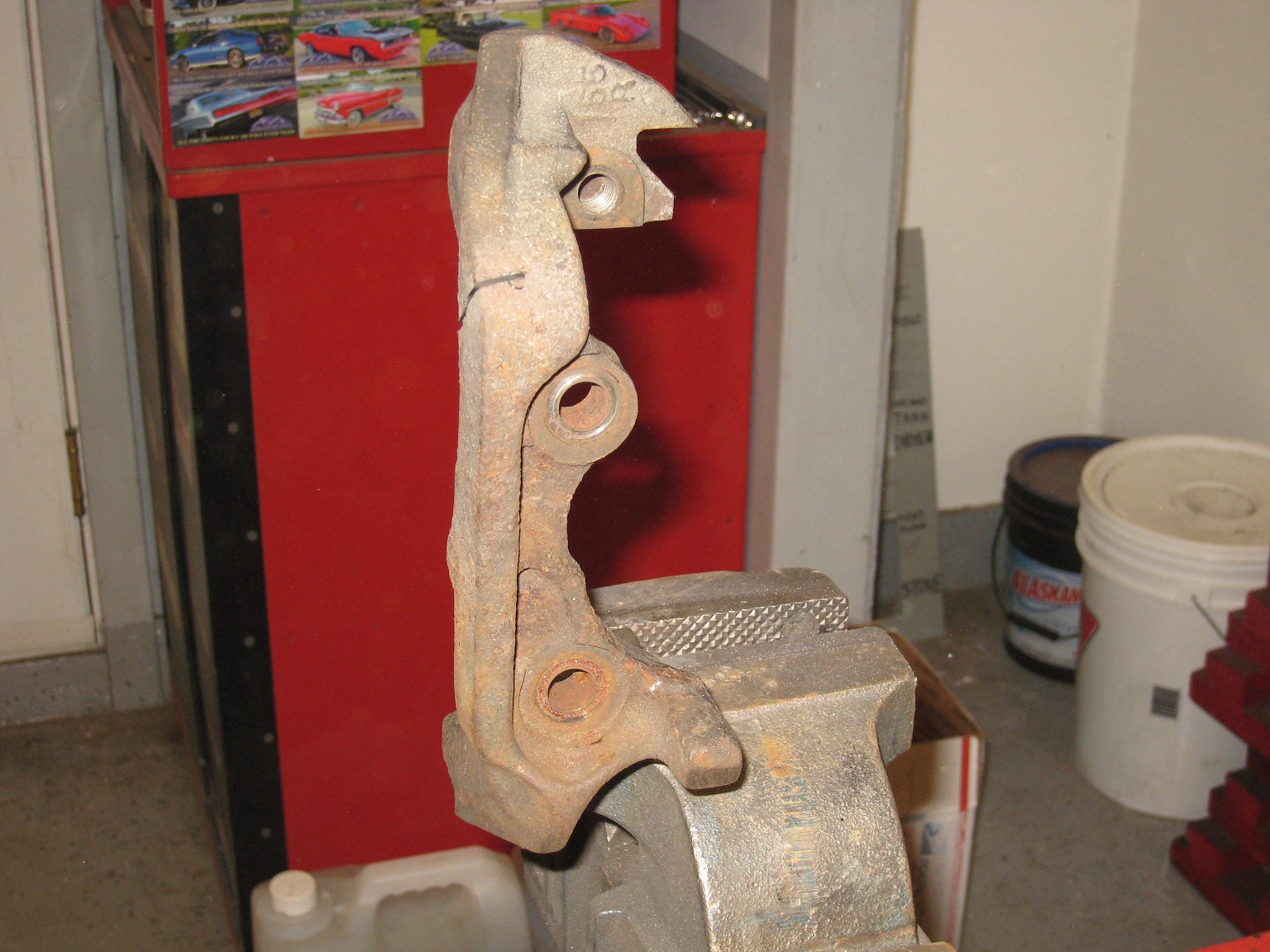
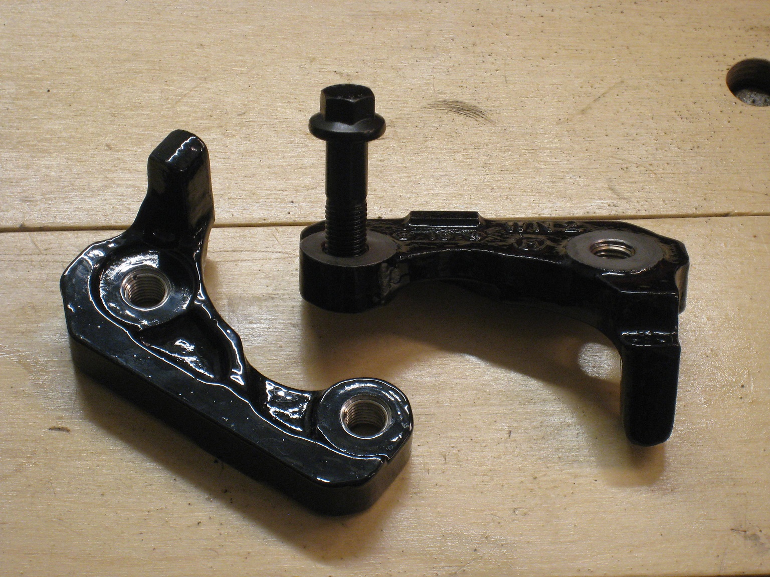
I've started working on the brake modifications for the White Bug. I'm largely reusing the brake setup I had on my previous Fiero (Zettner/Kohburn brackets with GM Metric calipers and 11.25" rear LeBaron rotors). I do however want to fix some unresolved issues.
One issue was the lack of steering stops on my old car, so the calipers would end up hitting the shocks. Not the stuff of a premium car. Therefore, I decided to retain the steering stops of the stock caliper bracket.
My Zettner brackets (and spacers) will be attached to the outboard face of the knuckle (could be machined) using M12 bolts, threaded into the stock caliper bracket on the opposite side of the knuckle. This setup brings the advantage of more bolt stretch, though loosening wasn't a problem before.
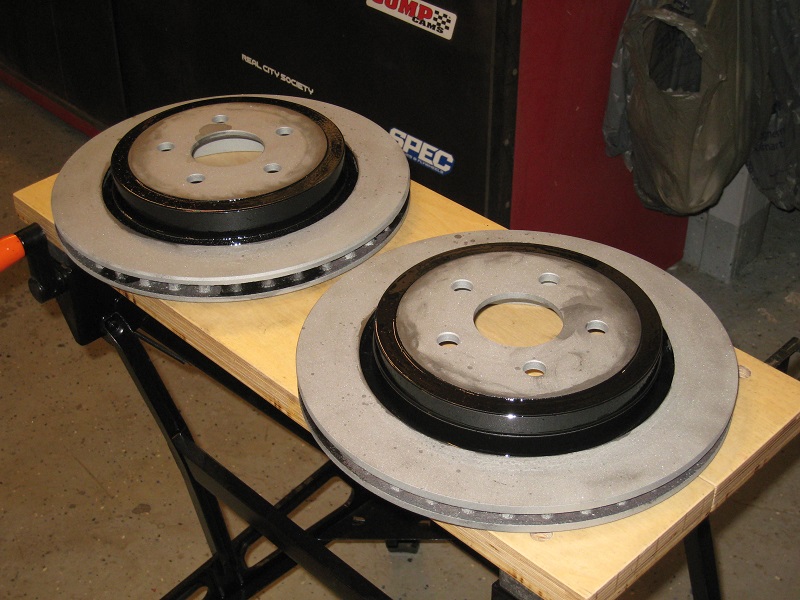
The rotors were still in good shape, so I decided to sandblast and reuse them. I painted the hats so they don't rust too quickly.
I'm debating if I want to drill/slot these rotors, or maybe just leave them plain.
For the moment I'm leaning towards slotting, because: I need practice on the semi-automated milling machine at work (don't want to get rusty) Drilling apparently leads to cracks, whereas slotting does not I already had drilled rotors on a previous car (my Saturn), so this would be different
I don't think I need slotting, it's more because it would be fun to do and give a subtle tuner car look. I would have to buy a small ball-nose mill for the job.
You can buy them slotted & drilled or slotted or drilled. For your application I'd leave them plain. I have the plain and with Hawks DTC 30 I have never had any brake fade. (I'm a very late braker) The only things I have are lots of dust and noise when cold, but not brake fade. That was with the 173WHP 2.8. Now with the goal of 350+WHP with the 3.7 I'm getting slotted and drilled rotors!
i dont know much about mechanics, but a little about physics. As i recall from my college days, we have a rotational force here and want to stop it, Thats a tork. A tork is force times arm. With 12" brakes instead of 9" brakes you are increasing the arm by 33%. With the S10 brake booster mod you are increasing the force by 40% cuz equal vacuum with 40% greater area, makes 40% greater force. The S10 booster mod is cheap and easy, even i could do it. The Corvette brake mod is not cheap or easy, am i right. imho the S10 booster mod gives more bang for the buck hour.
just my thots, cud be rong. Great looking car by the way...
jon
------------------ Astronomy says we will find a coded signal from outer space. Then we'll KNOW that life exists there, for coded signals aren't by chance.
Biology says there are coded genetic signals in every cell, but we KNOW that no intelligence created life.
I'm the original owner of a white ' 84 2M4 purchased Dec 10, 1983 from Pontiac. Always garaged, no rust, 4-wheel drifts are fun!
You really don't want to drill and slot the rotors yourself. They are cast parts with thicker and thinner spots. When you drill the holes, you are not removing the exact same material from every hole, which will lead to the need to have them rebalanced. When you buy drilled/slotted rotors, they have already been balanced post drilling.
I would say that going for bigger rotors, and reduced hydraulic pressures is in the goal of creating a firmer-feeling pedal. To me that's part of what makes a high-end car, so that's my objective.
I don't find the stock brake pedal effort to be excessive, so I don't think a bigger S-10 booster would give me the feeling I'm going for.
Besides that, I'm not really into the idea of becoming more dependent on the output of a stronger booster. That could create a Jekyll and Hyde car.
Pretty much like the Boeing 737 Max; flies one way in normal use, then when the electronics quit, it turns into a monster never before seen by the pilots.


 Glad you are making progress Patrick!