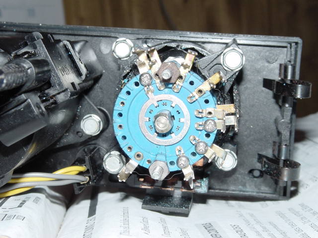
Originally posted by Gary W: Here is my rotary switch setup:
This is beautiful work. I have my new winter project. I want to replace the cable with a motor and make the whole thing electrical. I seem to have trouble finding that cable. It's probably available new, but the part number is not in my Firebird book.
Yes, you can use the 4 cylinder speedometer. The VSS doesn't know or care how many cylinders you have, all the speedomter boards are the same in this respect. You can use any speedometer to get the divide by two circuit.
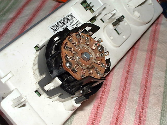
This is Roy's drawing for how he did the multiple layer switch:
Then this is how I did it with the single layer switch:
I think the single layer is the way to go, expecially if you want the detents to be in the correct position. It would be a nightmare to try and modify multiple layers the way shown earlier.
I am doing it the relay way, but a little different. So what exactly does each stock wire for the unit power.
Also, Do you have the speedo info I posted a few posts up? I am just a liitle confused since the display has more than six positions.
Thanks,
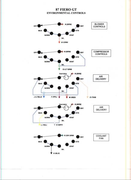
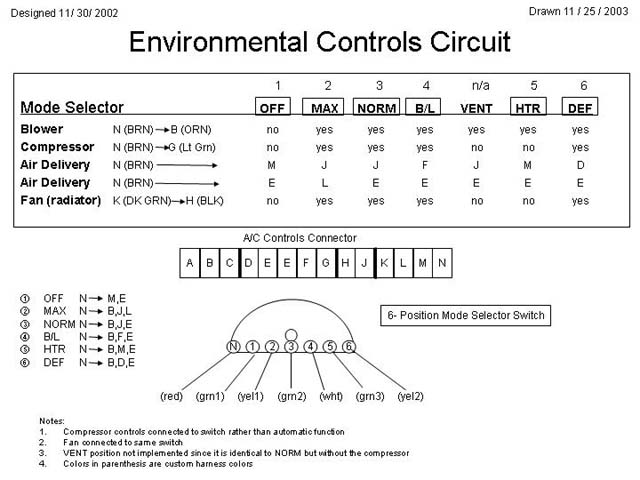
If I understand your question, the Fiero stock HVAC uses 7 positions, (including off). I used a 6 position switch only because that's what I was able to find. I just left the "VENT" out of the equation.
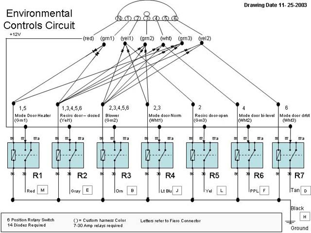
The 7 relays represent the 7 things that need to be powered, (It's kind of coincidental that they are both 7.) Depending on the way it's wired, (and using the doides it's one way) each position on my 6 way switch determines which of the relays are energized. The table shows you my logic for how I wired it up. The number of positions showing on the firebird HVAC does not matter since the switch moves independent of that.
As for your speedometer question, Gary says that the 4th pin down has the VSS signal on it. I haven't tried that yet, but according to him that's all there is to it.
I guess I just need a pinout of the wires themselves. I am using a potentionometer instead of a rotary switch. I am mounting it into the stock switch, so I keep my exact factory look (with proper notching movement). The potentionometer will give a different voltage at each position, and with a memory chip, each voltage will activate different wires; which will power the relays. I will be able to have all stock positions do something, so I need the exact pinout of the wires themselves.
On the speedo, I am not using the factory plug, so I don't know where to solder the vss sensor wires to. The 4th one down is the output wire. I need to know where the two input wires go.
I guess I just need a pinout of the wires themselves.
Well that's a clever wayto do it with a potentiometer and a voltage comparitor.
If you are working with the raw wires, then look at the drawing that I have A/C controls connector, (labeled A thru N).
What you are looking for is scattered all over the drawing but here is is neatly
A - Black -Ground B - not used C - not used D - Tan - Mode door defrost open E - Gray - recirc door open F- Purple - mode door partially open (bi-level) G - not used H - not used I - not used J - Light Blue - Mode door outlet open defrost closed (normal) K - not used L - Yellow- recir door closed M - Red - Mode door outlet open N - Brown - power
As for the speedometer board (84 non cruise, 85-88):
A - not used B - not used
C - not used D - not used E - not used F - not used
G - not used H - not used J - not used
K - not used L - not used M - 4000 pulse per mile buffered VSS (88 only)
N - 4000 pulse per mile buffered VSS (86-87) ?? per Gary W P - black/white - ground R - puple/white - from the VSS (low) S - Yellow - from the VSS (high)
T - yellow/black - Ignition power to cluster U - Dark green/white - 2000 pulse per mile Vehicle speed sensor signal to ECM and Cruise
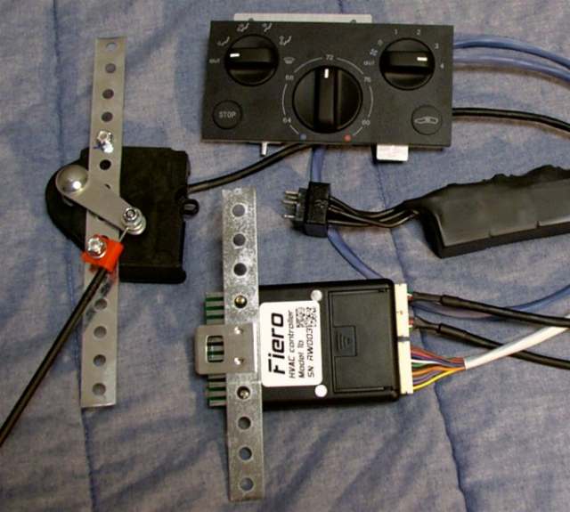
I've finally started working on the HVAC controller for my GA swap. I think I have the circuit for the mode selects worked out, using a single layer rotary switch. Some circuitry, no relays. I forgot to bring it to work so I could draw it up today, but I'll get it next week. I also ordered the actuator for the temp door, so that's covered with a single pot. The only kicker has been the blower control. I want all 5 speeds like my HVAC panel. I think I have that solved now, using a trailer brake. It will PWM the motor for various speeds based upon a pot setting, handle the power, and since I wrote the software for the brake, mods will be easy. I'll post more under my seperate thread later.
I've finally started working on the HVAC controller for my GA swap. I think I have the circuit for the mode selects worked out, using a single layer rotary switch. Some circuitry, no relays.
Bob
I'd be interested to see that circuit for the mode control, as well as your method for controlling the temp door. You are using a pot? I was considering using a 12 position rotary switch with preset resistance, but infinite control is cool too. Single layer on the mode door is the way to go especially if you mod it to worth with the preset "clicks" on the firebird HVAC.
Jonathon, I think you were following Riceburner98's thread on a dash swap in which he mentioned the GM actuator. It only needs a pot to set the voltage. He has a more comprehensive thread going in the tech directory at Ari's: http://69.94.88.210/index.php?topic=4103.0 He basically took it over with the HVAC controller he's come up with for the kit car guys. I think my mode select will work. From the info I recieved from Riceburner on the current requirements for the mode selects, a relay seems overkill. The switch should handle the current fine, and I'm adding a few more bits to it to get all the functions I want. I'll post it once I get a "visual" copy.
That kit Riceburner has is awesome! If only someone had something like that for us firebird guys. I like the fact that it mounts to the cable...that way you could retrofit without pulling the dash. Great stuff
[This message has been edited by jscott1 (edited 12-28-2005).]
The beauty of that actuator is that it does not have to use the cable. The way I understand it, it can also be mounted directly on the shaft. I think Don (aka 355Ferrari-I think) is using the cable, but Bob initially had it on the shaft. Since my dash is completely disassembled, this is the way I'd like to go. I'm trying to save as much room as possible for the toys.
Bob
[This message has been edited by RCR (edited 12-28-2005).]
Originally posted by jscott1: That kit Riceburner has is awesome! If only someone had something like that for us firebird guys. I like the fact that it mounts to the cable...that way you could retrofit without pulling the dash. Great stuff
I would definately buy something like that for my Firebird install if it were available!! I'm still not 100% sure what to do about HVAC - so this would solve that in 1 shot!!
I would definately buy something like that for my Firebird install if it were available!!
I can't make any promises, but a kit like that could be made for the firebird install pretty easy. Just replace the temp switch with a potentiometer and the vac mode switch with the custom one layer rotary switch, add the appropriate electronics and mount it up. This is on my list of things to do someday.
Jonathon: I've been going over this HVAC stuff repeatedly so I could figure how to do mine. I have the schematic done, I'll have to post it once I get home (can't post the images here at work). Mine seems overly simple, but I did simplify some functions. One question keeps popping up in my head, though: According to Bob (Riceburner98), the select functions only draw about 300mA. Why are a lot of these (including yours) using the relays? Seems like you could save a lot of wiring and space if you diode steer your connections directly from your switch to the Fiero harness. A 1 Amp 1N4002 would be sufficient for the job, and the switch itself would have no problems. Am I missing something here, or did someone miss the trees while looking at the forest....
Hey, my bedspread is famous now! LOL The initial prototype I did I just wired a rotary switch to the Fiero wiring, worked OK for me. I think the diodes and relays were used to allow 1 position / output on the switch to control 2 actual outputs.. I think. Also RCR is correct, it is fairly easy to mount that heat door actuator right to the top of the heater box. Just need to file down the little arm to fit inside the motor shaft, then attach the motor to the top of the box. (mounting it to the cable was to make "retrofit" installations easier without removing the dash) Also if anyone wanted to use it, the above mentioned setup for the 355 Kitcar guys will work just fine for the Firebird control, if you add the mentioned potentiometer to the Firebird knob. All it takes is a program change to match the voltages. There's an input for a seperate AC and reCIRC button also. When using the 355 panel, the heater motor needs to be modified to work on 5v (to be compatible with a future automatic climate control upgrade), but connected directly to a potentiometer on the Firebird panel it would work unmodified on 12v. You can get the motor new for ~$40 from GMpartsdirect.com, or from a junkyard for $1-$20. Not sure how much I'd sell just the plug-in "ECM" part of the climate control setup for, I had it all figured out at home on paper somewhere.. But as long as mounting the multi-position switch to the Firebird panel works out OK, then that would seem to be the cheapest / easiest way to go. ----> Just looked at the actual link about the switch from RCR, that's awesome work!! Out of curiosity, how much does the brake controller go for? I never got my PWM circuit working for the fan speed, maybe adding a modified controller to the kit would be an option? I personally don't like relays myself.. (although I just bought 550 of them to build kits! LOL)
------------------ Bob Williams Multi-colored '86 Mutt, a work in progress! (3800SC running great! Fixed the bent roof, now I need an intercooler! Yeehaa!)
I finished up the mode select today. There were a couple small issues with the original circuit I came up with. I needed an extra diode to block feedback current in the re-circ circuit and I found that I can't drive to modes at the same time, thus I no longer have a feet/def function. I'll post a new schematic once I can update it at work.
Did you guys use the Firebird cable for the temp knob on the heater controls???
...the one other question, does one need to use the buffered 4000 ppm signal or can it just be fed straight from the VSS signal (what exactly does the buffering do)?
Yes, I used the cable from the Firebird, but I'm trying to develop an all-electric alternative similar to what the kit car guys are doing.
You can feed the speedometer directly from the 4000 PPM VSS but as it leaves the VSS it varies in amplitude depending on the speed. Therefore at low speed it's going to be a very low voltage and lead to erratic behavior of the speedometer.
The buffer turns it into a square wave, (digitizes it if you will) so that the pulses are uniform at all speeds. You can use the speedometer board and tap into the signal downstream of the buffer but before the divide by two circuit.
...and, hey if you need someone to test your above 'electric' controls you can put me on the list Although I would need an entire kit as my car is using manual controls (no AC).
Tim
[This message has been edited by Mickey_Moose (edited 01-26-2006).]
I just wanted to add some things here that I have ran across (not mentioned before) so others that are looking at this project are aware of as well:
1) 99+ gauges will not work for this swap - well they will partially work, but most of the indicators are controlled by the ECM. Pin outs for the 99+ gauges are also different than what has been posted here. Don�t bother with these ones.
2) Everything works as it should on the clusters that have the analog odometer, those gauges with the digital odometer - the fuel gauge does not work as it is ECM controlled. However, the fuel gauge from the analog cluster will fit the digital cluster (you also have to use the needle that comes with the gauge as the center pin is a different diameter). See the next post for the small mods needed for it to work.
3) The clusters with the digital odometer use LED�s for the warning lights � back lights are still with bulbs.
4) V8 clusters - the tach will not be correct for a V8 car or a V6 car - these clusters are set up for a DIS system. I am currently looking at how to modify them for a correct reading.
5) Fiero defrost vents interfere with the dash. You either need to remove the mounting tabs from the dash in that area, OR notch the defrost duct work. I rather notch the duct work just so there are extra points to hold the dash
6) Firebird heater controls. You will also need the hot/cold select cable from the Firebird so that it will fit the control. I have yet figured out a way to mount it to the Fiero air box. The Fiero has a smaller pin than the Firebird on the door actuator.
7) I have yet to figure out a decent method for using the Firebird heater controls with a car that does not have A/C (manual slider controls vs the push button one). Will most likely have to be converted to an electric system.
8) The dash needs to be notched at the ends to clear some metal pieces in the car � OR � you can trim the metal parts. You only need to do this if you are trying to get the dash as close to the windshield as possible.
9) console needs to be trimmed to fit (as well as the metal areas previously mentioned).
�ok, so far that is all the things that I have come across, I am sure there are more as I get further into in�please feel free to add anything...
[This message has been edited by Mickey_Moose (edited 01-31-2006).]
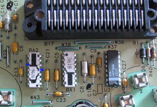
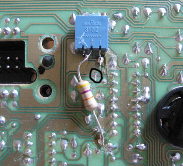
On the front face of the circuit board you need to locate RA2 and the 2 pins that connect the resistor that sets the tach calibration. The pins are marked in blue in the following picture: (note RA1 is used for calibration of the speedo)
Once you have identified the traces on the backside, you will need to cut one of the traces and install an appropriate size pot for the calibration. You can measure the original resistor and multiply it by 0.75 (if a V6 dash going to a V8) to get the value of the new resistor. I just stuck in a 100k ohm pot with a 47k ohm resistor in series � didn�t have a bigger pot to use. I then just adjusted the pot till the tach read right according to my scanner). I cut the trace marked with the black circle � it was just a soldering pad on the board and in case this did not work to my liking it would have been an easy fix
Fuel gauge in reference to a 98 dash:
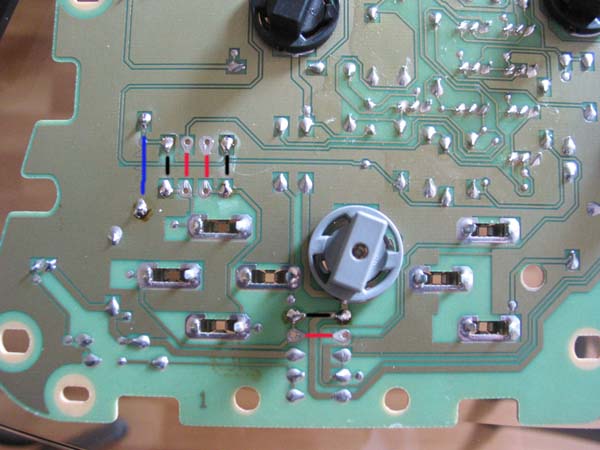
On this cluster the fuel gauge is ECM controlled and needed to be replaced. I replaced it with a gauge from a 94 cluster, however some board mods were needed as it was not a direct plug in.
Referring to the picture below: - remove the 3 jumpers marked with a red line. - Install the 3 jumpers in the spots indicated by the black lines - A 24 ohm � watt bias resistor is installed in the spot marked with a blue line
It was nice of who ever designed the 98 cluster to include these traces for the old style fuel gauge.
Hope this helps someone out Tim
[This message has been edited by Mickey_Moose (edited 01-23-2023).]
Thanks for the awesome and informative post. Some of what you posted was covered in the previous 18 pages but some is new. I already knew the 99+ gauges were not applicable, not even close to the same pinout. I have a 98 in mine with the Digital OD but I had to replace the fuel gauge.
The digital OD was actually a midyear switch on the 97 and it remains to be seen if the fuel gauge will work on those. I suspect it might, if so then the 97 would be the best of both worlds.
I have never connected a V8 gauge so thanks for the heads up on the tach modification. It looks like I will be doing that mod quite a bit. The only one I have set up so far have been V6 and they are a plug and play. But a lot of people doing this swap have a V8.
The 97's still use the old fuel gauge (from what I have seen), which is probably why the PCB was designed with both gauges in mind to account for a future upgrade.
I also just wanted to put some of the info in one post, as some of it gets lost in all the posts
If you find out something about modifying the tach on the V8 clusterl let us know. In the mean time I probably will modify the V6 clusters for V8 instead. Can't have the 150 mph speedo that way but oh well.
If you find out something about modifying the tach on the V8 clusterl let us know. In the mean time I probably will modify the V6 clusters for V8 instead.
No problem - and actually that was a V8 cluster that I modified - the V6 cluster will modify the same way. With the V6 cluster you multiply the resistor by 0.75 to get the new value, on the V8 on you have to multiply by .5 to get the new value (in theory, I set the pot up to the new calculated value, but I still had to adjust it a couple of turns to make it read right - the .5 value is obviously off).
BTW: how much longer did you extend your bracket for the steering column and any pictures of where you bolted it to in the car? Did you remove the lower bracket as well?
quote
Can't have the 150 mph speedo that way but oh well.
Yea - us Canadians have to suffer with the crummy 250 ones
Tim
[This message has been edited by Mickey_Moose (edited 01-23-2023).]
Do you have any more of those metric clusters? There is someone in the UK that is interested in one. I never see those on ebay even though I include Canada in my searches.
As for the steering column bracket, I didn't make any measurement, but from eyeballing it, it is about 8 or 9 inches, (20-23 cm) The top bracket is cut off from the vehicle side. The new bracket mounts to the hoop where you cut off the bracket but further towards the windshield. I used really long screws to bolt it up.
...ok, you have me a bit confused with the steering column thing. The column has 2 brackets to hold it up, you removed/modified the top one and reattached it to the original mounting points. The other end you just screwed up into the sheet metal above it. The lower bracket is still intact - correct?
Also, do you happen to have the pinouts for the defrogger switch on the HVAC control? They are not marked on the housing as to which is A. B, C or D
[This message has been edited by Mickey_Moose (edited 02-02-2006).]
power window connector >> 12101915 - AC Delco number PT187 power mirror connector >> 12085536 - AC Delco number PT144 power door lock connector >> 12101862 - AC Delco number PT254 light switch connector >> 12125632 - AC Delco number PT544
...but these puppies are expensive...
Edited to added the AC Delco part numbers...if there are others, let me know, and I will look them up.
Does anyone know the part number for the firebird headlight switch connector? I can't find it in my parts CD. I hear it's ridiculously expensive, but I would like to find a source for it at any price.
[This message has been edited by jscott1 (edited 03-30-2006).]


 I want to replace the cable with a motor and make the whole thing electrical. I seem to have trouble finding that cable. It's probably available new, but the part number is not in my Firebird book.


.jpg)
_1.jpg)


 Out of curiosity, how much does the brake controller go for? I never got my PWM circuit working for the fan speed, maybe adding a modified controller to the kit would be an option? I personally don't like relays myself.. (although I just bought 550 of them to build kits! LOL)