I'm just going on what the service manual says about its function. You may very well be correct that this tube has to be present and hooked up in order for the OE Fiero 2.8 throttle body and IAC system to function; if so, I stand corrected on my previous statement. I haven't researched the inner workings of the stock 2.8 to the extent of knowing everything possible about this particular design. But assuming what you say is true, and someone wanted to use a later design lower intake manifold, they would also have to use the later style throttle body so the IAC would continue to function.
Yep, gotta have air flow to affect the idle. The IAC air passage in the manifold runs full length, and there are holes in each port to allow the air to enter the head. It's probably easiest to look at it as primarily a cold start fuel delivery system that they tacked the IAC function onto. The constant air flow also prevents fuel from lingering after the cold start injector is done.
I bought the ECM and coil pack already and was excited to put the distributor less ignition in and then re-read and realized I couldn't. If I can get this fitted to the balancer, thats the last thing I'm missing correct? (minus the knock sensor and a burned chip)
If its just a plate with notches in the right place, and just a normal senor to pick up the position, I might be able to make it. Provided with the info on what degree the notches have to be at and what sensor to use.
[This message has been edited by bnevets27 (edited 03-13-2008).]
yes - that will work just fine. if you figure out how to mount - there is another guy looking to do the exact same thing. I will post a link to his thread, if I find it.
Originally posted by Madess: need a clarification D5 tan / blk est bypass move to BC7 must be disconnected to set base timing, see note1 below
what exactly does this mean?
also just wondering if anyones knows the colors of the wires in the c203 adapter that correspond to the terminals I am supposed to be using?
the original Fiero ECM - the ALDL connector allows you to bypass the EST - the 7730 does not. so, instead - you break the connection between the ECM and the igntion module on the tan EST wire. easy way to do this instead of a connector, just mount a switch somewhere. hit the toggle to set the timing. or maybe a 1/8" mini jack, where inserting or removing the jack opens or closes (depending on taste) the EST line.
the original Fiero ECM - the ALDL connector allows you to bypass the EST - the 7730 does not. so, instead - you break the connection between the ECM and the igntion module on the tan EST wire. easy way to do this instead of a connector, just mount a switch somewhere. hit the toggle to set the timing. or maybe a 1/8" mini jack, where inserting or removing the jack opens or closes (depending on taste) the EST line.
so if the timing is already set right on my car, just hook everything up and go, with a switch, then if for some reason I want to play with the timing, just turn the switch off, time it, and turn it back on... I get it.
If you are going to put a switch or other, non-weather sealed connector on the EST bypass wire, make sure you do it inside the car. Otherwise corrosion could attack a non-weather sealed connection which could cause problems in the long term.
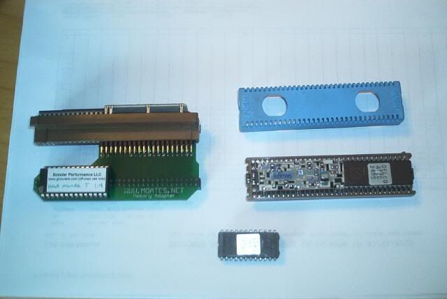
how do i install my ostrich onto my 7730 v6 memcal? here is a picture of the components that i have am i missing somthing? do i need to remove any thing and do i need to soider anything? please help
[This message has been edited by 3.6lvvt6spdgt (edited 03-21-2008).]
The Ostrich takes the place of the prom. The prom is the brown chip on the right side of the memcal in the picture. The rectangular black piece with the pins on bottom and holes on top (middle right of picture) is your quick connector used when you need to connect and disconnect your prom several times. Keeps from tearing up the memcal's prom socket. So, remove prom (note the little U on the right end), insert black rectangle chip adapter with U on the right (if it has one), then insert Ostrich connector (bottom right in picture) into quick connector with U on the right. The Ostrich is now doing the job of the prom. The other chips on the left of the memcal in the picture are the limp home mode stuff. Those stay put.
Anyone? Did I miss something?
[This message has been edited by Hudini (edited 03-21-2008).]
Small screw driver with care and patience. It's just pressed down onto the memcal, there is no solder.
No, it is soldered; at least every one is I have seen. You can either unsolder it to remove it, cut the legs off with a dremel tool, or get a mem-cal adapter like what is shown here: http://www.moates.net/produ...25_36&products_id=32
ok got the brown chip out, there might be some sodier it just looked like some corroision that needed to be cleaned off, the chip removed easy with some time, the problem now is the cable does not go all the way in due to the second board on the memcal and i cant tell whitch way the cable connects it does not have a U notch in it?
[This message has been edited by 3.6lvvt6spdgt (edited 03-22-2008).]
ok got the brown chip out, there might be some sodier it just looked like some corroision that needed to be cleaned off, the chip removed easy with some time, the problem now is the cable does not go all the way in due to the second board on the memcal and i cant tell whitch way the cable connects it does not have a U notch in it?
The ribbon cable coming from the adapter should have a red stripe on one of the ends. That needs to face away from the knock sensor interface circuit board on the mem-cal. If the circuit board is in the way of your socket, you can carefully push it away a little bit but not too much that you damage it. If you don't have enough room for the socket I suggest you order the G1 mem-cal adapter from moates.net.
This is a very good topic I am going to look through all of it. I plan to do this myself. I have a 3.4L and just bought the ECM and a wiring harness. I will need the rest of the parts.
Ed
------------------ Fino www.feroce.net Member National Kit Car Club www.kitcarclub.com Lifetime Member CFOGi (Lot of good that does me)
I am putting a 3.4 DOHC engine in my car and some say that this ECM will work some say it wont . I think it will if it will run the igntion system it should be able to run the rest of the engine it just might take some tinkering on the tuning to get the fuel and spark correct like any othe engine
Thanks Darth, that's why I asked for someone else to respond. I used the Moates G1 Memory adapter like you suggested. He did not have that in his picture.
EDIT: Here is what the Moates adapter with memcal looks like (top left), memcal by itself (top right), and prom by itself (bottom).
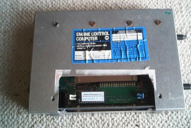
And Moates adapter with memcal installed in the ECM:
[This message has been edited by Hudini (edited 03-23-2008).]
^ thanks, i needed that! ive had the moats adaptor but darth just send me a new prom and i forgot how to connect the oem prom to the adaptor. wow perfect timing
I've been watching this topic for awhile. I'm ready to try it but am having trouble finding the 7730. I've tried Ebay and emailing one of the folks that said they could get some here. Still no luck. Any ideas on where to get the neccessary parts?
I've been watching this topic for awhile. I'm ready to try it but am having trouble finding the 7730. I've tried Ebay and emailing one of the folks that said they could get some here. Still no luck. Any ideas on where to get the neccessary parts?
Darth - (regarding this upgrade for a 3.4 pushrod or 2.8 stock engine) waaaay back you mentioned doing the DIS with this ECU upgrade. What parts are needed for the DIS - coil pack, module (under the coil pack). Distributor (?) - will it fit the 3.4 / 2.8 fiero engine ?
[This message has been edited by PaulJK (edited 03-30-2008).]
Darth - (regarding this upgrade for a 3.4 pushrod or 2.8 stock engine) waaaay back you mentioned doing the DIS with this ECU upgrade. What parts are needed for the DIS - coil pack, module (under the coil pack). Distributor (?) - will it fit the 3.4 / 2.8 fiero engine ?
I'll take a stab at this one: If you are using the 3.4 (or 3400) block, you will have a crank trigger wheel and sensor available to trigger the DIS system (coil packs, module). If you are using a stock 2.8 there is no available crank trigger wheel or sensor which would require an aftermarket unit (none are available as I know it). There is a company making a crank trigger wheel and sensor, but only can be used with the FWD lower damper/pulley. I am currently in contact with this manufacturer to see if one can be made for our stock 2.8 setup (which is like a RWD damper and separate pulley). My current thought is to machine the protruding portion of our damper (where the pulley mounts) flat with the face of the damper ring and sandwich this guys trigger wheel between the damper and pulley. I know our damper is 6 3/8" in diameter, I just don't know the diameter of the manufacturer's trigger wheel yet.
.... if you are swapping in a newer 3.1 or 3.4 that has provisions for the DIS ignition system, I would recommend using the DIS as well.
I just read this in the first post on page 1. So it seems you need to have a 3.4 that already has provisions for DIS. So ryan, nevermind my DIS question (I guess). I'd still like to get your input about the digital cruise control - on a STOCK 3.4 pushrod / 2.8 V6, can you use the digital cruise control with the ECU upgrade or do you still need to add a speedometer interface like the ones from Nordskog or Dakota Digital ?
I just read this in the first post on page 1. So it seems you need to have a 3.4 that already has provisions for DIS. So ryan, nevermind my DIS question (I guess). I'd still like to get your input about the digital cruise control - on a STOCK 3.4 pushrod / 2.8 V6, can you use the digital cruise control with the ECU upgrade or do you still need to add a speedometer interface like the ones from Nordskog or Dakota Digital ?
Yes the Dakota Digital SGI-5 should interface with the stock Fiero speed sensor and output a signal the "digital" cruise control can use. Of course if you swapped in a 7730 ECM, then you could just use it's output.
But before you buy an aftermarket module, you might want to try something. I was looking at the wiring diagrams for the 88 Fiero and found there was a different signal that went to the proposed electro-hydro power steering module. This signal came out of terminal M of the stock Fiero speedometer connector. It is possible that this may be a 4000ppm signal which you could use for the "digital" cruise control. Now in a stock Fiero there probably will be no such wire or terminal hooked up to this position in the speedo's connector (unless you were one of the rare lucky persons to get ahold of a power-steering equipped Fiero), so if you want to try this output you will have to obtain the correct terminal that will insert into this connector; you MIGHT be able to reuse one of the terminals out of the stock Fiero cruise control module connector. Otherwise, you will need to find another Fiero speedo connector and pull a wiring terminal out of that one. But I think trying this would be worth a shot vs. buying an aftermarket module.
[This message has been edited by Darth Fiero (edited 03-31-2008).]
Here is a wiring diagram from a 1988 Fiero that shows the proposed electo-power steering VSS wire. This wire might be a 4000ppm signal that can be used with the "digital" cruise control...
If that doesn't work, and you don't want to buy the aftermarket SGI-5 interface, you should be able to use a factory GM speedo buffer box from a 80's GM car. These boxes look like this:
This yellow "4-out" buffer box was used in many mid-late 80's GM cars such as the Pontiac Firebird, Pontiac Grand Am, Chevy Cavalier, etc; and can usually be found piggy-backing the ECM.
But before getting one of these buffer boxes I encourage someone to try hooking up to that "M" terminal coming off the stock Fiero speedometer to see if that works.
-ryan
[This message has been edited by Darth Fiero (edited 05-16-2008).]
Here is a wiring diagram from a 1988 Fiero that shows the proposed electo-power steering VSS wire. This wire might be a 4000ppm signal that can be used with the "digital" cruise control...
If that doesn't work, and you don't want to buy the aftermarket SGI-5 interface, you should be able to use a factory GM speedo buffer box from a 80's GM car. These boxes look like this:
The wiring diagrams for this buffer box can be downloaded here: VSSbufferWIRING.jpg
This yellow "4-out" buffer box was used in many mid-late 80's GM cars such as the Pontiac Firebird, Pontiac Grand Am, Chevy Cavalier, etc; and can usually be found piggy-backing the ECM.
But before getting one of these buffer boxes I encourage someone to try hooking up to that "M" terminal coming off the stock Fiero speedometer to see if that works.
-ryan
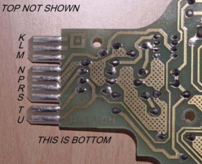
It does not look like there any wires going to those three terminals by the only photo I have now.
The pins we are using now are P R S T U and the 3 before that are nothing.
Ed EDIT: One of those four holes is the 4K signal and if you have an oscilloscope or just a COMPUTER SAFE test light the wire could be found by testing each wire while you turn the wheels, the one that blinks on and off will be the 4K signal. I don't think this is the best way you still have to get the wire out to the engine compartment. The speed buffer box could be used in the engine compartment and get all connections needed there.
[This message has been edited by Fino (edited 03-31-2008).]
EDIT: The first photo is an 85 MPH speedo and the second is a 120 MPH speedo. Look at the extra circuit on the 120 MPH that is not scratched it does not go up to the 4 holes but I wonder what it is. You might think a ground but that screw goes into plastic. ??????????
[This message has been edited by Fino (edited 03-31-2008).]
Remember, GM usually skips letters like "I" and "O" in their wiring terminal ID's so they aren't confused with the numbers "0" and "1". Looks like terminal M is hooked up to the circuit board and isn't used in a stock Fiero application minus pwr steering (it lacks the marks you can see made on other terminals by connector being plugged in).
[This message has been edited by Darth Fiero (edited 03-31-2008).]
My car does not have a computer in it now or I would test it to see if the test light to ground flashes. This would be very easy for anyone to do by using a computer safe testlight and probe the terminal. It is very easy to get to.
Ed EDIT: Note that "P" and "R" connect together. That would be low VSS and Ground.
[This message has been edited by Fino (edited 03-31-2008).]
Bet it is. Looking closer at the wiring diagrams for the stock Fiero speedo, you can see the 2000ppm VSS output from the speedo circuit board hooks up a to "divided by 2" logic circuit. The output terminal for the power steering module hooks up to the "divided by 1" logic circuit, which would stand to reason this is a 4000ppm output. I think it's worth a try.
Originally posted by Darth Fiero: Bet it is. Looking closer at the wiring diagrams for the stock Fiero speedo, you can see the 2000ppm VSS output from the speedo circuit board hooks up a to "divided by 2" logic circuit. The output terminal for the power steering module hooks up to the "divided by 1" logic circuit, which would stand to reason this is a 4000ppm output. I think it's worth a try.
-ryan
Ed
EDIT: Remember the speedo has to be a 120 MPH speedo the 85 does not have it. Now on later cars will it be there? I don't know what year my 85 MPH speedo was.
[This message has been edited by Fino (edited 03-31-2008).]
EDIT: Remember the speedo has to be a 120 MPH speedo the 85 does not have it. Now on later cars will it be there? I don't know what year my 85 MPH speedo was.
I've got a 1985 Fiero GT cluster sitting here with the 85 MPH speedo and it does NOT have the completed circuit board connection to terminal "M". Don't have any "newer" non-GT speedos here so I can't say whether or not term M is hooked up on those.
This is a pic from Jon. I think terminal M was active on the '88 models and terminal N was active on some of the earlier years. In this pic, looks like M isn't connected to anything but N is.
I was gonna test these terminals tonight, but i have 3 buffer boards and NONE of them have any circuits connected to K, L, M or N .
[This message has been edited by PaulJK (edited 04-01-2008).]


.jpg)


.jpg)
.jpg)


 .
.


