Well I now have a black dash! Nick was kind enough to send me some of the tint that he used on his interior in this Thread
It's similar to a thick "paint" and has a sponge tip applicator on the end of the tube. It's very easy to use and goes on very well with excellent covering ability and is quick drying. I did two coats just to make sure that the coverage was uniform. Here's the before color: And the tinted dash: The pictures don't really do it justice. It looks like a brand new dash!
Thanks Nick! I owe you one!
[This message has been edited by Sourmug (edited 07-25-2007).]
I'm currently trying to source a supply for the 3" aluminum tubing I need to make the modified 3.4 DOHC intake. So far it looks like they expect me to make a minimum purchase of 10 linear feet. I don't need 10 linear feet! The thing that irks me is that the vendor I'm dealing with has this statement on their web site:
quote
�Welcome to the online home of Assorted Metals, Calgary's premiere small volume metal supply shop. At Assorted Metals, we know that "a minimum order" can be frustrating when all you need is 5 feet, so at Assorted Metals, no order is too small, yet our prices are surprisingly reasonable!�
They're looking to see if they have some short lengths laying around so hopefully they will have some.
In the meantime I'm puttering along with the beginnings of the engine swap. Here are my resource manuals: These are printouts of various threads from PFF and other places pertaining to the swap. My thanks to everyone here who has taken time to document what they have done! It will be very helpful and I have given +'s to you all.
So to start I thought I might as well begin with the mounts. I will be using the Dodge 318 mounts mentioned in numerous threads and so the stock tranny mounts need to be modified. Here's what I began with: After a nice little fire the rubber is separated from the mounting brackets: Actually, I must admit that I'm surprised that the only thing that held the mounts together was the strength of the rubber bond to the metal bracket. Once that was done the brackets were cleaned up and the existing hole in the bracket was drilled out to 1/2" to match the 318 mounts. The stock Fiero engine mounting bracket was cut as described elsewhere and also an additional 1/2" hole was drilled for the 318 mount as well. Here they are after painting:
Here's a shot of the 318 mount. They are larger than I expected: They have a small bump on one side that needs to be ground off to allow them to lay flat. They also needed some slight trimming to suit the Fiero brackets. In This shot you can see how the mount doesn't lie flat properly due to the mount plate being overly long:
I placed the mount into the vice and trimmed the plate as needed and after painting it was installed: Additionally, a small window needs to be cut into the cradle to accept the mount bolt/nut on the rear tranny mount. This is the location from the top side marked out: And the mount in place as seen from the underside: Here's how all three mounts look sitting in place: And the cradle ready for the engine/tranny:
I have painted the exhaust manifolds and various heat shields with 1200 *F high temperature ceramic impregnated paint: I'm also using aluminum cradle bushings. First thing I did was clean out the bushing sleeves with a brake hone: and the bushings were test fitted and additional honing was done as needed: That's it for tonight! Nolan
[This message has been edited by Sourmug (edited 08-01-2007).]
I have cleaned up the fuel tank and installed the new 255 LPH fuel pump. Here's the before: And the after: The tank is nice and clean and the three hoses have been replaced with new. The tank is now reinstalled into the car, one more item off the list!
I have replaced the axle shaft seals with the new axle support bearings that I purchased from Rodney Dickman. The old seals were pried out: It takes a little bit of effort but they come out clean.
Then the proper locktite (the stuff that Rodney sells) was applied to the new support bearing: And the bearing was placed into position: And the bearing installation tool was used to hammer the new bearing in place: Once seated the bearing opening was masked off and the bearing was painted. These are unfinished steel so they need some protection. Probably not to interesting for those of you who are experienced at this sort of thing but there's plenty of us who have never done this sort of thing so I thought that I would post how I did this.
I have installed the fly wheel, clutch and attached the transmission to the new engine! This is a BIG milestone for me as the clutch is what took my car off the road to begin with. I'm really excited!
Here is the clutch plate from my old 2.8 if your curious: It had completely disintegrated, when I was passing someone on the highway of course, and naturally when the engine came out I suddenly had grad plans for the car So yes, this is a big event for me: And TA DA!!! And once again the was much rejoicing!!
Fun reading this.... That Ceramic paint is going to come off. I give it a year.
I hope to have a shop like yours one day where I can work on mine.
Yes is suspect that it will eventually come off but by then I may be ready for a turbo, we'll see. We purchased this house 4 years ago in part because it's on a pie shaped lot that allowed me to build a decent size garage. I don't know what it's like where you guys live but new houses up here are almost all built with attached garages on the front of the house and they are usually only about 20'X20' which is too small for what I wanted. I have never had a garage before and I think it would be hard now not to have one. I hope you end up with a nice one too someday, you'll enjoy it.
Ewww!! Nolan, I like your wheels. More info, please?
Bob
Hi Bob:
The wheels were purchased on E-Bay, here's the LINK
I should point out that they did not send all the accessories that were supposed to come and one of the wheels is mismatched. These are mistakes that would be easy to make and they are in contact with me about correcting this. I'll let you know how it works out. They do have a good feedback score so I'm sure it will be resolved "BUT" I wouldn't run off and buy a set just yet until this is resolved.
Nolan
[This message has been edited by Sourmug (edited 08-05-2007).]
Just did some tinkering this weekend. First off I finished all the fiberglassing for the console. I made a pocket for the billet aluminum cup holder bezel that I purchased here it is in the finished pocket: This is the pocket and cups: And the paint: Once the paint is fully dried I will sand off the over-spray on the flat armrest and start covering the armrest.
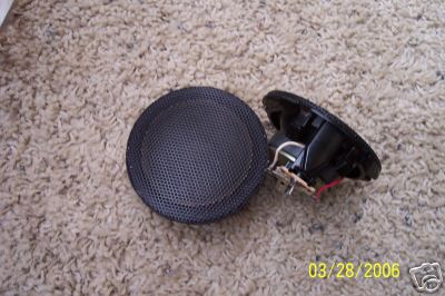
And I installed some new rear speakers. Here's the plates that I purchased: And how they compare with the speakers that were in the car: As you can see, the magnet is considerably larger on the new speakers. In fact they don't fit into the existing mounting opening. The stock plastic mounting plate sown in the next picture had to have the oval opening enlarged: To do this I remove a porting with a cut-off wheel in the dremel and then used my spindle sander to enlarge the rest: Here's a shot of the existing speaker opening: This too had to be enlarged. The side towards the front of the car on both sides is right up against a structural member. You can see a large bolt hole to the right of the opening. this is for the upper seatbelt attachment. The is a little bit of sheet metal that can be bent with a hammer to make the opening larger but no much on that side. On the back side of the opening I cut out a crescent shaped portion to increase the opening: Once that was done the two speakers were mounted:
Just a quick note: As I indicated earlier, I received one mismatched wheel. The vendor has sent me a replacement wheel along with the missing hardware, just incase anyone was wondering about that particular E-Bay vendor.
Nolan you are doing some fantastic work. The mod you needed to mount the rear speakers reminded me of what I had to do. Are you going to be adding woofers behind the seats or will your door speakers be enough?
I will be using the same small format sub and amp that Fierosound is using in this Thread Here's a picture of the sub: Additionally, I will be using the Stealth dash mounted tweeters:
I have also finally started to dig into the wiring for the dash swap. This is, I must confess, my weakest technical area. But, hey, I'm in this to learn so no more procrastinating. Using the stealth wiring diagrams I have started the pin-out sheets for the various connectors. Here are some pictures of the pin-outs and their actual connector. Each connector diagram is of the back of the connector where the wire enters. I hope you can use this information but of course it's at your own risk. Your gauge pod may have different features depending the car it's out of.
First off, here's the mess I'm working on and the entertainment The next two are out of the 3000GT '92-'96 service backup electrical manual and show the approximate locations for the D series connectors in the dash and console:
The main connectors are D-03, D-04 and D-05 for the main gauge pod and D-09 for the axillary gauges. Here's the back of the main Pod: D-03 goes into the lower right port, D-04 into the upper right port and D-05 into the left port. Here's the back of the Axillary gauges: The port on the left is for the D-09 connector.
I have excell files for the connectors and larger .jpg's of the configuration diagrams if anyone needs them.
I'm working on compiling pin-outs for some of the other connectors and will post that info once I have it. Again, make sure you check your pin-outs if you use mine, I could be wrong.
I have been working on the doors. First off I replaced the hinge pins and bushings: Using the lift sure made it easy. I just removed the bolts attaching the door hinges to the car frame and disconnected the wiring. Make sure you mark the hinge locations before you pull the door off though. This gives you plenty of room to work. I highly recommend this if you have a lift. Here's a shot of the reinstalled door/pins: I have also replaced the door glass as mine had the usual scratches. The outer dew wipes were replaced as well. Here are the rivets that need to have their heads ground off: As you can see, the one on the left is ready to be removed. The rivets are then driven out using a hammer and punch. I didn't even break anything! Here's all the hardware that comes off once the rivets are removed: And the old glass removed: There are a few plastic guides that have yet to come off in the picture above. These are just snapped into the holes in the window and can be gently pried off.
[This message has been edited by Sourmug (edited 08-26-2007).]
Here's the new glass: And after a trip to the tinters: The glass is easy to reinstall. I used 1 1/4" long 1/4" bolts with lock-nuts instead of replacing the rivets. The hardware that was remove just snaps back into place, for the most part. Once the glass was in place and the bolts inserted I applies some blue locktite just to be safe and tightened the nuts onto the bolts. As I understand it you have to be careful not to over tighten the nuts. Once done the excess bolt length was trimmed off:
I have also started to install the after-market door locks. As I previously indicated, I will be using ltlfrari's write-up on his site as a guide. Here's the actuator attached to a bracket that I fabricated: And the assembly attached to the door: The bolts are again 1/4" bolts 1 1/4" long. Holes were drilled so that the bracket sits just above part of the door mechanism when attached and a nut was placed between the door and the bracket as a spacer.
That's all for now, except that the E-Bay vendor who sent the wrong wheel has replaced it with the correct one
I have to say Nolan, I always smile when I see there is an update to your thread. Not just for your quality of work, and innovation, which I have to say are impressive, but also for the care you take in documenting everything you do. I am pretty sure I count myself among many others when I say that yours is one of the build threads I measure others against as far as quality of info goes. Any how, keep up the great work... .and the great thread.
Thanks for the comments. I must admit that I enjoy posting my progress and it helps me see the progress that I have made. It's a big job and it would be easy to let it slide because of it's size. Seeing the progress I have made keeps me encouraged but not as much as the encouragement I receive from other members such as you.
One of the things I found in my car was that the speaker cloth had faded quite a bit. The front speakers are of course gone because of the dash swap but the rear speaker grilles need some work. The grilles are heat welded to the interior trim and if you try to remove them they will break the plastic pins that hold it in place. Here's my solution to the problem.
When you pull the grilles off this is what you will see, first the holes that are left in the trim piece: The larger round hole is for the upper seat belt attachment. And the back of the grilles look like this once the existing fabric has been removed: Here's how the plastic pins look: There's no easy way to re-weld these back on so a different attachment is required. On the face of the grilles there are four small dimples that are over-top of the pin locations on the back. These are a result of the injection molding process and fortunately show the exact positing of each pin. The dimples can be hard to see but are visible in good light. I ground the pins off smooth on the back side and marked the dimples with a sharpie marker. I the drilled out the dimples to suit #8 machine screws on the drill-press. I'm suing screws with a tapered head and need to flare the holes so that the screws sit flush with the grille surface. To do this I used a conical grinding stone in my dremel: And carefully using the dremel on a low speed I matched the hole to the tapered screw: The screw are then held in place with nuts on the back side:
[This message has been edited by Sourmug (edited 09-05-2007).]
After a test fit the grilles were then sprayed with a black self-etching primer and were left to dry overnight: I purchased some grille cloth from Rodney Dickman, it comes in two rectangles large enough for the front speaker grilles: And to attach the cloth I coated the grille faces with 3M spray adhesive: The fabric was laid onto the grille after the adhesive was applied and carefully positioned and stretched so that it lays flat and smooth at the corners. Heres the back side after the cloth was attached: And after the trimming to size: The spray adhesive is very tacky and the cloth sticks to it right away. Make sure your work area is clean. I then used a heat gun to run a bead of glue along the back of the grille and folded the excess cloth over the back edge: The grilles were then inserted onto the trim piece and attached with nuts. And the extra screw length was cut off and the nuts secured using more heat glue: And the final product:
I have also started my LeBaron brakes. I will be using the 10* offset rear bracket for the swap. Here the brackets are all painted with high-temperature caliper paint: And I also wanted to paint the rotors so that the exposed metal doesn't rust up right away. First the friction surfaces were masked off: They were then painted silver with the same type of paint: Since I am using the Camaro front calipers I removed the ridge around the hose fitting connection: And then the metal surfaces of the calipers were cleaned with solvent and painted again with caliper paint: The brackets were then attached to the rear knuckles:
The knuckle needs to have some of the metal trimmed away due to the larger rotor size. Here you can see the interference: I used a cutting wheel in the angle grinder to do the cut. First I cut the tab like so: After some test fitting I determined that some more had to be removed as it interferes with the brake pad when the caliper is installed. The second cut was done here: The removes a small "horn" shape where the bare metal is exposed in the picture above. The brake pads that I'm using are the front pad for the Camaro all around. On the front caliper there is a pocket in the piston that accepts a clip on the back of the pad. The rear calipers don't have this pocket so the clip needs to be removed. This was done with the grinder: Once the back was smooth it then clipped into the caliper nicely: The Inner pads also need to be cut due to some additional interference with the knuckle. In the picture below the bottom edges of both inner pads has been trimmed. As I understand it this is only needed for the 5* and 10* offset brackets. Once done the calipers and pads were placed into position: Now I'm just waiting for the metric bolts for the front brackets.
Nolan
[This message has been edited by Sourmug (edited 09-07-2007).]
Just a little side note (or two) on the Dodge motor mounts: 1) The little bump on the mounts are to locate them & keep from turning when tightening. Instead of grinding them off, you should drill a hole for them. 2) There is another version of the same mount that has metal flanges, to grab if the mount fails (or maybe even before). Sorry I don't know the part # for them. ~ Paul aka "Tha Driver"
Thanks for the comments. The mounts are now in place and tight and there didn't seem to be any real problems with rotation. However, I see what you mean about the bumps and how that could make a difference.
Just tinkering around so I thought I might as well have a look at the trunk. With the 3.4 DOHC going in I wont be keeping the fan in the trunk so this is as good a time as any to have a look at what's involved with removing it. I have never had a real good look at the trunk sheet-metal so I wasn't sure what exactly I would find. After pulling the trunk seal and the carpet here's how it looks, first the bottom: The passenger side with the fan: And the driver side: A little bit of rust but not too bad at all. There is no evidence of the rust spots on the exterior surfaces. I brushed on the Rust Mort that I have been using after the spots were wire brushed. After it sits the rust starts to turn black:
The fan and the ductwork were removed and this leaves some penetrations that need to be capped. Here's the fan inlet: and the two penetrations into the engine compartment (from the trunk side): To cover these three areas I decided to make some sheet-metal blanks. The ductwork had two metal flanges that have rubber seals on both sides of the flange. These hold the duct in place and make the mounting points for the engine bay air tubes: I used these as templates for the blanks:
[This message has been edited by Sourmug (edited 09-09-2007).]
Using the back of the fan housing as a template and with some test fitting and cutting I made the blank for the fan intake: The blanks were primed and painted. And then installed into the car. The fan intake: The two duct fans were reinstalled and sealant applied to the back of the blanks and they were then bolted in place. And the two trunk ends after the rust clean-up: Nolan
I thought that I would tackle adapting my after-market steering wheel this weekend. If you recall, I purchased this wheel some time ago: But I did not purchase an adapter. One of my concerns is that the majority of adapters that I have seen end up moving the wheel closer to the driver. This is something that I don't want as I want it to end up in the stock position. So I thought that I would try to adapt the stock wheel mount to the after-market wheel. Here is the stock GT wheel: As you can see there is a metal hub/mount behind a plastic shroud on the back of the wheel. There are four small rivets that hold the plastic shroud and the plastic front plate in place. These rivets are relatively loose fitting and will spin if you try to drill them out. I just used a small punch which drove the rivets through the plastic clips. Note: this will probably crack your plastic tips. Once the plastic pieces were removed there are six screws that hold the wheel to the hub and they are now accessible: Once the screws are removed the hub is now free from the wheel: The new after-market wheel has a large aluminum center cap that houses the horn button. This cap is held onto the wheel by six machine screw with nuts on the back of the wheel. Naturally the circumference of the circle that these screws are on is smaller than the circumference of the stock screws so they won't line up. Fortunately the two sets of screw holes are all spaced at the same angle and I was able to draw lines between the holes to help line up the stock hub. Here's a picture of the hub placed onto the new wheel to show the difference you can also see that I have marked the required hole locations with a transfer punch. And the wheel with the hub removed showing the marks and the punch locations: The new holes were then drilled through the wheel and counter-sunk for the hub screws: The aluminum frame of the wheel required some grinding due to a raised burr being formed during the drilling. This won't be visible on the end product.
[This message has been edited by Sourmug (edited 09-16-2007).]


 I especially love the door panels. Great work!

.JPG)
.JPG)
.JPG)
.JPG)
.JPG)

 I owe you one!
.JPG)
.JPG)
.JPG)
.JPG)
.JPG)
.JPG)
.JPG)
.JPG)
.JPG)
.JPG)
.JPG)
.JPG)
.JPG)
.JPG)
.JPG)
.JPG)
.JPG)
.JPG)
.JPG)
.JPG)
.JPG)
.JPG)
.JPG)
.JPG)
.JPG)
.JPG)
.JPG)
.JPG)
.JPG)
.JPG)
.JPG)
.JPG)
.JPG)
.JPG)
 So yes, this is a big event for me:
.JPG)
.JPG)
.JPG)
.JPG)
.JPG)


.JPG)
.JPG)
.JPG)


 Nolan, I like your wheels. More info, please?
.JPG)
.JPG)
.JPG)
.JPG)
.JPG)
.JPG)
.JPG)
.JPG)
.JPG)
.JPG)
.JPG)
.JPG)
.JPG)

.JPG)
.JPG)
.jpg)
.jpg)
.JPG)
.JPG)
.JPG)
.JPG)
.jpg)
.JPG)
.JPG)
.jpg)
.JPG)
.JPG)
.jpg)
.JPG)
.JPG)
.jpg)
.JPG)
.JPG)
.JPG)
.JPG)
.JPG)
.JPG)
.JPG)
.JPG)
.JPG)
.JPG)
.JPG)
.JPG)
.JPG)
.JPG)
.JPG)
.JPG)

.JPG)
.JPG)
.JPG)
.JPG)
.JPG)
.JPG)
.JPG)
.JPG)
.JPG)
.JPG)
.JPG)
.JPG)
.JPG)
.JPG)
.JPG)
.JPG)
.JPG)
.JPG)
.JPG)
.JPG)
.JPG)
.JPG)
.JPG)
.JPG)
.JPG)
.JPG)
.JPG)
.JPG)
.JPG)
.JPG)
.JPG)
.JPG)
.JPG)
.JPG)
.JPG)
.JPG)
.JPG)
.JPG)
.JPG)
.JPG)
.JPG)
.JPG)
.JPG)
.JPG)
.JPG)
.JPG)
.JPG)
.JPG)
.JPG)
.JPG)
.JPG)
.JPG)
.JPG)
.JPG)
.JPG)
.JPG)
.JPG)
.JPG)
.JPG)
.JPG)
.JPG)
.JPG)
.JPG)
.JPG)
.JPG)


