Yeah thats what i wanted too... guess my description wasnt all too clear.. hehe.
I want to pick up some 4" tube and try to run it to the stock location. Maybe at LEAST 3.5".
I dont know but i doubt that the Civic one is large enough. I was just going to weld something together like i did for my exhaust. I had a guy that was willing to take a look at making a custom intake for the SC Fiero application. He makes one for the GTP as it is and is located NEAR my house but i think he wanted like 200$ for the GTP one. Although i think his included a custom S.S. scoop piece to pic up the cold air from under the GTP bumper.
...WOOO HOOOO PAGE 7!!!!........
[This message has been edited by The Fieromaster (edited 09-07-2005).]
IP: Logged
06:39 PM
Rickker Member
Posts: 268 From: Kingston, ON Canada Registered: Feb 2002
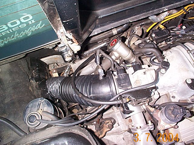
It is indeed very similar to dryer ducting hose, except it has a heavier gage wire and an industrial rubberized material for the casing. The nice thing, is that it matches the 4" bore on the K&N, as well as the molded rubber tube that came with the 3800SC, which in my case was from a '99 Buick Regal. My objective was to get the air intake out of the hot engine compartment. And, like you, I wanted a 4" system to minimize inlet losses. This engine pulled 270 RWHP @ 5200 on the dyno last year, using this intake system. ....Rickker
IP: Logged
09:34 PM
The Fieromaster Member
Posts: 4124 From: Painesville, Ohio USA Registered: Jun 2001
Hmmm.. i think i know EXACTLY what your talking about. I used to work for a dust collection business and we designed systems for companies. One of the "owners projects" was designing a Mulch Blower for landscaping. A company sent us a bunch of different flexable tubings and one that looked JUST like what your saying and have pictured i remember... Lets see here...
Remember when going for something like this you want it to NOT crush under vacuum, dirty filter causes higher vac before TB specially with boosted engines!!!
I found a few different types on McMaster Carr's web site...
One is flame retardent and can handle up to 28" of mercury (vacuum) � Use with air, paint and weld fumes, smoke, lint, and grinding dust � Temperature Range: -40� to +250� F � Flexibility: Flexible � Abrasion Resistance: Good � Compresses 35% of extended length � Color: Black � Material Meets: UL 94HB Also known as TPE (thermoplastic elastomer), the blend of PVC/polypropylene and rubber gives this hose its flame-retardant qualities. Hose has an enclosed spring steel wire support. Material thickness is 0.022". Use a worm-drive clamp (see pages 212-215 ) to attach hose. Can be used outdoors.
This one handles 25" of Merc
General Purpose Blended Polypropylene/Rubber Duct Hose
Black Withstands higher temperatures than PVC. Material is also known as Santoprene or TPR (thermoplastic rubber). Hose has an enclosed copper-coated steel wire support. Material thickness is 0.030", except for 1 1/4", 1 1/2", and 1 3/4" ID hose, which have a thickness of 0.026".
There are a couple others on there too but those are the best. If anyone wants part numbers i can give you them... All the 4" duct seems to be priced AROUND the same... 4-6$ per foot some/most have 5 foot minimums.
Do you have any more pics of your intake Rickker??
ZZP sells a 4" intake tubing that is $10.50/ft. It maybe the same as what you found in the McMaster catalog. But this is shown to work well with the GTPs.
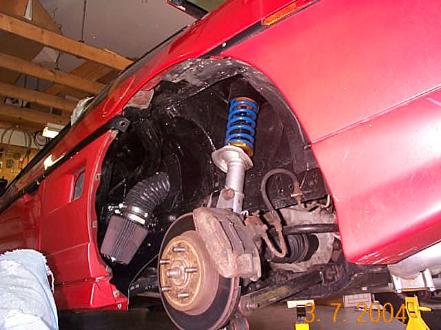
Rickker, on a side note, did you doing any mods to get the coil over to sit flush on the stock spring perch of your strut?
Does it snow in Canada? Yes, there was a lot of grinding needed. Frankly, it was a PITA. When I purchased the coilovers from WCF, I did not realize that so much rework would be needed on the (brand new) KYB strut. However, now that it is behind me, I am pretty happy with the setup.
...Rickker
IP: Logged
02:08 PM
Rickker Member
Posts: 268 From: Kingston, ON Canada Registered: Feb 2002
The fuel rails came from ZZP. They are kind of hard to come by as they never have them in stock. Just keep an eye out and sooner or later they'll have some around..
ZZP sells a 4" intake tubing that is $10.50/ft. It maybe the same as what you found in the McMaster catalog. But this is shown to work well with the GTPs.
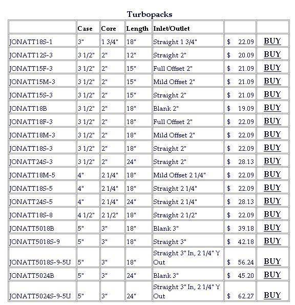
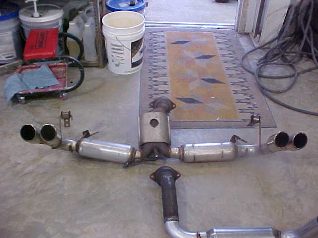
Yeah i do... would you like the "Turbo Packs" or the "Glass Packs" because i have a sinking horrible feeling that my exhaust will drown out the space shuttle launch!!! It is totally open... From what i was told when i talked to "LiL-Devil" he suggested i use the turbo packs cause they are quieter but still flow awesome.
My mufflers are 12" long and you can SEE how tight a squeeze it is in there.. Problem is they dont make a Turbo Pack that short unless you want 2" pipe...
Here is the product list for turbo packs...
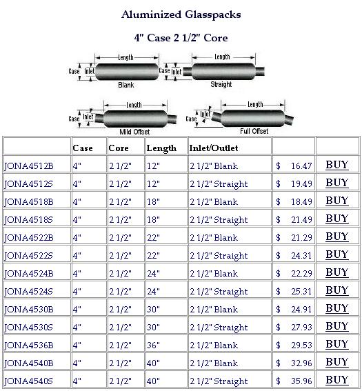
Here is the list for the Glass Packs (what i used) in 2.5" pipe size (what i used) I have - pn# JONA4512S on my car...
Are you going to need a cat converter?? If so you could go with something like THIS....
Just so ya know you can take that oil filler cap extension off if you want to. Just un twist it like the cap and take cap off extension then just put cap in the valve cover... goes right in!
Anyone else using Intense Racing's oil filter relocation kit?? It didn't come with any sort of instructions, and there is this little rubberized washer thingy that we don't know what to do with. We're still waiting to hear back from intense and wondered if anyone here knew...
Well, we got the answer. Turns out its a seal for the outside of the oil pressure set screw, "whodda thunk it?"
If you look under the capture nut for the oil pressure adjuster screw, you can see the thin 'washer':
Edit, before someone mentions, the plugs in the IN/OUT are just there to fill the void until we get this thing in the car and can fab up the braided lines..
[This message has been edited by Jncomutt (edited 09-11-2005).]
Just wanted to add some insight regarding the mounts we purchased. The transmounts and engine mount came from Tony, very good price and fast shipping.
As you can see, this tranny mount fits perfectly and required no modification:
This is the opposite mount. As you can see the pointed corner hole didn't line up. It needed to be 'shimmed' out some, as well as made to fit. Due to the fact that the hole is on a 'point' we weren't comfortable modifying this section. I don't know why the mount is made pointed. It looks as though it could be square and still get the get the job done. Although it was made this way, so hopefully there is a good explanation. To fix the problem, we used the carbide bit with a dremel and simply slotted the holes on the other edge of the bracket, so this pointed one without much 'meat' could fit correctly.
And here it is made to fit:
Now for the front Engine mount. This mount required two holes to be modified. If you look at the first picture, you can see they both needed to be elongated left/right. Rather than modify both of them to fit that 'slide', we just ovaled out the single hole on the left. This placed both holes in line with the holes in the block. Now we had the top two bolts to fit. The lower right bolt still required a lot of upward cutting. Again, the dremel fixed this in about 2 minutes and wasn't even something to sweat about. Just wanted to make it known that the mounts took a little massaging to fit.
And for now, here is the mount from WCF for the shifter assembly. Apparently they WILL make the 'correct' bracket to make up for the holes being on different planes, but we ordered the one for what trans we had, and it was still not right. Rather than send it back for the correct one, and deal with waiting again, and the hassles of shipping,etc., we had no problem just shimming this to fit as well..
[This message has been edited by Jncomutt (edited 09-11-2005).]
IP: Logged
03:40 PM
The Fieromaster Member
Posts: 4124 From: Painesville, Ohio USA Registered: Jun 2001
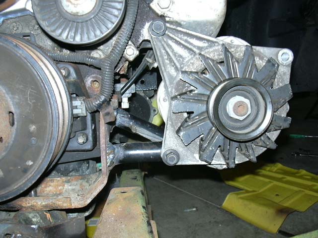
Well i have my alternator mounted and correctly spaced out, i will be using the old stock alternator bracketry to make the new stuff... Should turn out pretty sweet.
Will try to get some pics tommorow... i am missing my other cam mem stick which sucks. Damn gremlins
Well i have my alternator mounted and correctly spaced out, i will be using the old stock alternator bracketry to make the new stuff... Should turn out pretty sweet.
Will try to get some pics tommorow... i am missing my other cam mem stick which sucks. Damn gremlins
you cat stole it gota love those physco cats
oh and thats my line there buddy
[This message has been edited by crazyfieromike (edited 09-12-2005).]
Hey man.... Tryin to keep ya motivated here.. Any updates on the wiring or pictures of your final belt routing, etc???
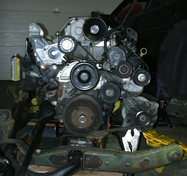
Here's another in progress build pic to keep the thread going..
You are going to have to change out the SC tensioner with one from a GTP, the steel version. The one you have will hit the firewall under heavy acceleration and cause false KR. There is a guy selling one on Club Go now for like $20.00 or so.
Yep, we figured as much. We have a cut down version on the OBD1 car that is going in the 84, while we weren't sure on this one, predicted we MAY have to swap over to the other one. Everything is still in test fit/mock stage, but its good that we have others on here helping us along that KNOW for sure what will and will not work.
IP: Logged
09:43 PM
The Fieromaster Member
Posts: 4124 From: Painesville, Ohio USA Registered: Jun 2001
Well first of i sat for some time trying to figure out the best way to mount the alternator... I already had the top bolt figured out, and the spacing too (15 10mm washers) so it was now that i had to figure out how to tie in the other mount on alternator (in front) and the back bolt too (for support)
I decided that for the front i would chop up the stock alternator brackets... They are as they would be stock on the alternator...
Taking the angle off and the bar leaves you with this...
Now the best i can i will try to explain how i did this.
NOTE--- DO NOT cut anything before reading WHOLE post.. hehe, not that you would anyways but im telling you ABOUT where to cut stuff... you will have to cut it for yourself so that you get the proper location on your 'Nator
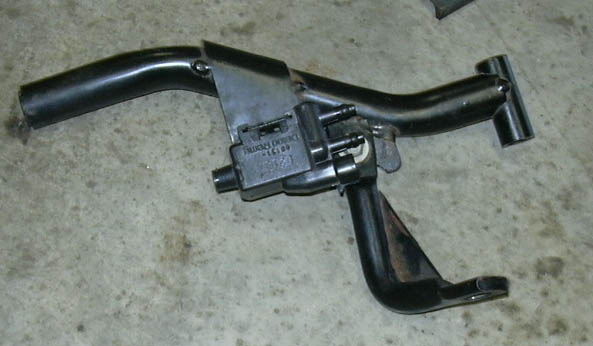
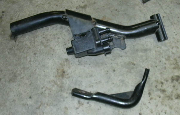
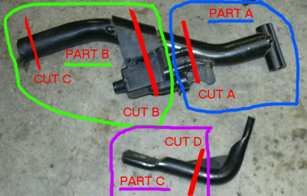
Below is a pic of how i cut everything up to make the parts i needed. There is allot going on in the pic so i will explain it out, sorry i have no in process shots but Mikee the action shot guy is not around cause gas is Thirty Billion Dollars a drop.. hehe!!
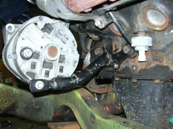
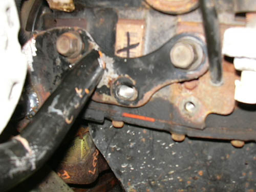
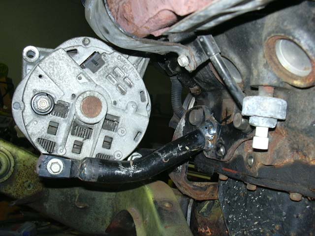
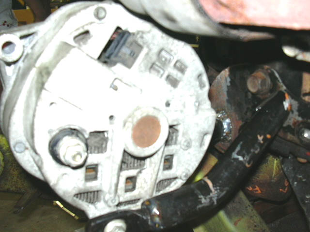
First off i took the large tube bracket and cut off ALL the other brackets on it, the sylonoid bracket and the U shaped steel piece near "CUT A". Normally the side near "CUT A" bolts to the blower, NOT anymore!! Circled in GREEN and labeled as PART A is the new BOTTOM BRACKET. This will bolt to the hole in the bottom of the alternator (in back) and be welded to the super thick engine mount. I then made the rest of the cuts on that tube (CUT B and C) to leave me with PART B. This will become the rear mount. However, after making the cuts you will not have any good way to bolt it to the alternator SOOOO... You take the other bracket piece and cut it at CUT D to make PART C.
Well the Lower Mount (PART A) is already done so lets forget that for now and move onto the REAR mount... It now will begin to read like assembly instructions for some back yard play set... After cutting Part B out, which you need to do at CUT B and C (c - because there is a nut welded in the end of tube) you will then take PART C and make a cut at CUT D. Cut the angle OFF of PART C leaving behind just round stock with a flattened end with hole. NOW basically PART C just slides in the end of PART B.... make sure you put it in the end of PART B near where you made CUT C.
This will get welded in place but NOT YET because you need to make sure it all lines up right before tacking together.
If you have the alternator properly spaced, I checked and RE-checked the belt travel and alignment. Should be perfect.....ish.
I basically have the top bolt in the block and through the long "wing" of the alternator. I then rotated it up so that it was close to the manifold heat sheild but DIDNT touch it. Also not so low that the belt hits anything (like itself at the water pump pulley which is close squeeze).
Then all you do is measure from center of bottom bolt hole to the engine mount to get length for PART A... now you know where to cut it at CUT A.
To get the length for PART B just measure from bolt hole in back of the alternator to the mount and subtract about an inch or so so that you have some room for PART C to stick out (flat spot with hole is there for a reason).
At this point with you would have everything cut to length... I bolted on PART A and then pushed it against engine mount to make sure it fit right and i had good angle on alternator (not to close to sheild and not to low for belt path). Then if all is well just TACK weld it GOOD into place. Remove alternator CAREFULLY and weld PART A to the mount.
I then put the alternator BACK ON and bolted it all down snug and checked fit and belt again...
Now you can figure out PART B... I bolted PART C to the alternator then slid PART B over top of it and lined it up where i wanted it on the engine mount... Did some looking around and clearence checks (dont want to block off ANY access to your engine mount bolts or it will never come off) LOL! Now just tack weld PART C to PART B. Remove the tacked assembly and weld it GOOD and SOLID! I then put the assembly BACK on the alternator, checked alignment onto the engine mount and tacked it to the mount NICE and STURDY.... Remove the alternator once again and weld the piss outta that tube to the engine mount...
TA-DA thats it... hard core solid mounting.
Here are some pics and short descriptions of the setup...
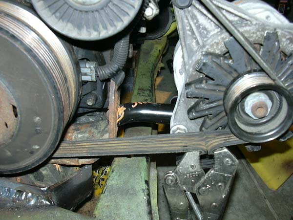
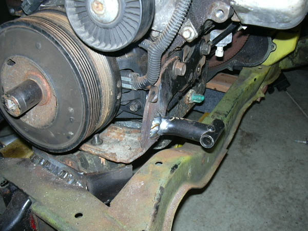
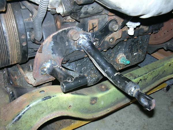
Here i am testing the position of the bottom mount... The bend goes towards the FRONT and so does the SHORT end of the tube where bolt goes...
Here is the bottom mount welded into place...
MORE TO COME SOON... Just wait for the post!!
I dont have any pics of the back mount as a seperate PART B and PART C but here you can get the idea of how its fitted together... here i am lining up the location on the engine mount...
Here is a BAD SHOT but it shows about how you have to watch where you put back mount... there be bolts to dodge hehe!!
[This message has been edited by The Fieromaster (edited 09-12-2005).]
IP: Logged
09:53 PM
The Fieromaster Member
Posts: 4124 From: Painesville, Ohio USA Registered: Jun 2001
Sweet!! I was waiting for you to post that, The OBD2 car seen above has AC and loyde's low mount alt, however the 84 OBD1 car is no AC, and so I've come up with something similar. I'll post pics some pics of that setup later on too...
IP: Logged
11:17 PM
Sep 13th, 2005
crazyfieromike Member
Posts: 581 From: mentor ohio 44060 usa Registered: Mar 2002
Also i should note that ALL the bracket attachement holes on that side are SLOTTED, so in order to keep the mounting location repeatable (doesnt move if bracket is moved) i am welding washers OVER the slots so that they are basically no longer slotted holes. Ill do this with the bolt tighened down (all bolts tight) so i wont get any warpage on washer or so anything wont move on me...
IP: Logged
05:32 PM
Sep 14th, 2005
RandomTask Member
Posts: 4539 From: Alexandria, VA Registered: Apr 2005


 I need to visit and check this stuff out in person. Cant wait until you get it running.


