Before anyone starts... I have no desire to do a 3800 (supercharged or otherwise). They are an excellent engine, but they are way to common for me...
The ground rules: The engine will remain stock and retain the CPI - no performance upgrades (I already have an 88 SBC fiero) Serpentine belt drive - located as close to the engine as possible AC will be retained 4 speed auto - non-electronic (car currently is 5 speed isuzu) Engine will by poly mounted Z-style adapter plate with thickness increased to 3/4" Cost will be kept to a minimum This car is being built for a spirited daily driver.
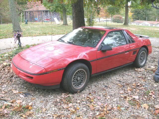
The lucky fiero is an 88 base model coupe I picked up for $800 with a rod knock 4cly. Its current 2.8 is going south quickly, so I need to do an engine swap to keep the car drivable.
The engine is a 93 4.3 Vortec CPI from an Astro van purchased for $250 with all accessories/wiring/ecm (I removed after driving the van around the yard). I also have 92 Bravada with the 4.3 CPI - hit deer last winter and it is just sitting around incase I need any other parts.
The trans is a 4 speed auto from an 86 Buick Rivera. It has been sitting on the shelf since 97 when I removed it from a running parts car. It is not the strongest version, but it will work for a while and I can replace it later if needed.
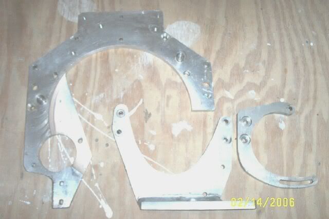
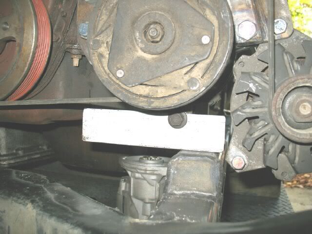
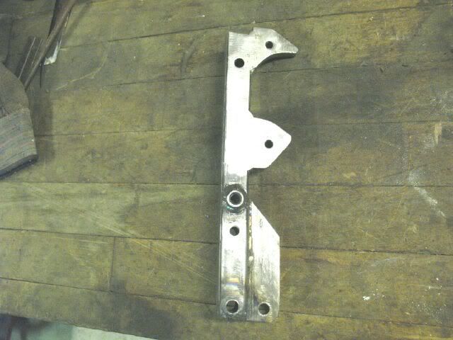
Here is an adapter plate I picked up. The interesting part is that it rotates the engine relative to the tranny. This one is just over 9/16" thick, so I will use spacers to shim the tranny 3/4" from the engine. The only part from this pic that will be used is the adapter plate.
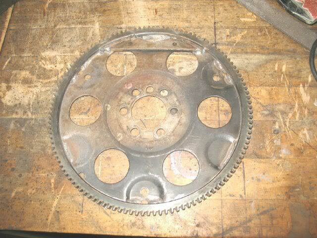
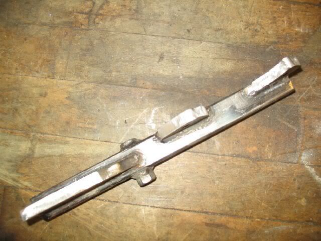
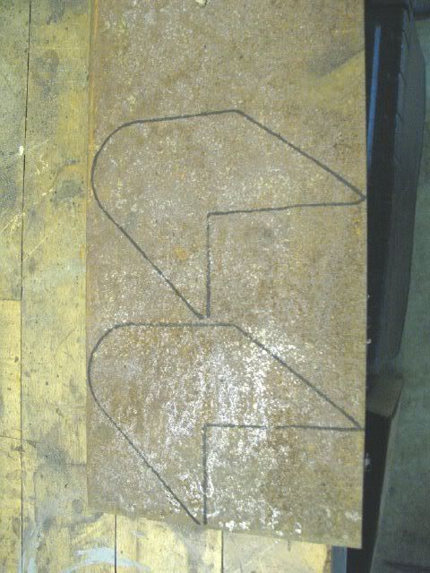
The flex plate was made using a 4.3 153 tooth flexplate and turning it down to fit inside the Nissan 120 tooth ring gear. Make sure to use the 153 vs. the 168 because the raised portions for torque converter attachment are in a better location on the 153 tooth version. Here is the modified flex plate. The holes in the pic are for the FWD converter, the old RWD holes are where the ring gear is now: I still need to fabricate/install the spacers between the flex plate and the torque converter.
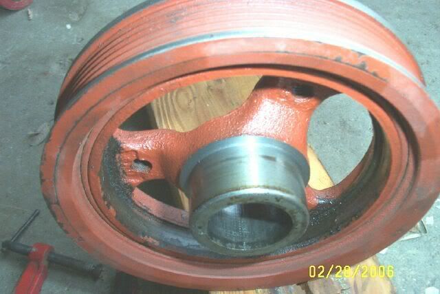
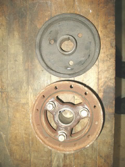
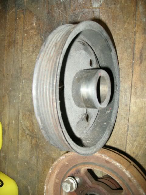
The balancer will be from a mid 90's 3.1 cavalier. It is a balancer/crank pully all in one and accepts the 6 rib style belt common with the 88 4 cyliner Alternator/AC compressor. The seal surface on the backside was turned down further to the front to allow it to be placed as close to the timing cover as possible.
[This message has been edited by fieroguru (edited 10-28-2007).]
IP: Logged
04:30 PM
PFF
System Bot
fieroguru Member
Posts: 12462 From: Champaign, IL Registered: Aug 2003
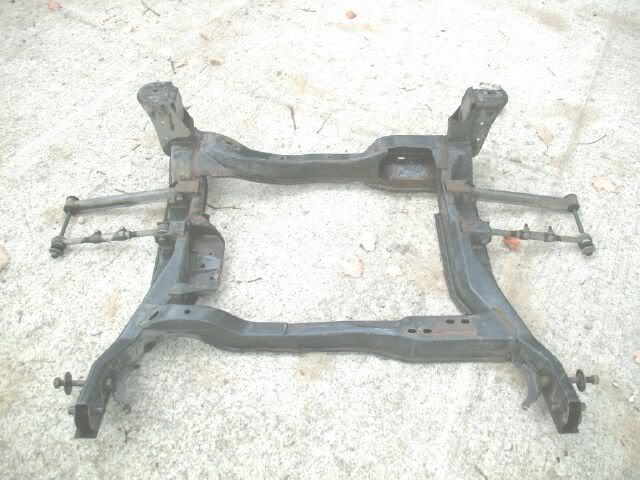
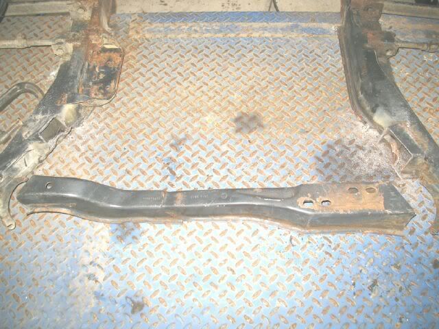
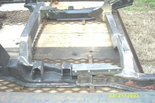
Next step is the cradle. Here is a spare 88 cradle the swap will start with. It weighs 62lbs as shown in the pic.
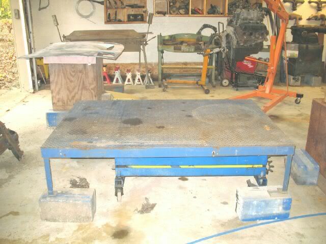
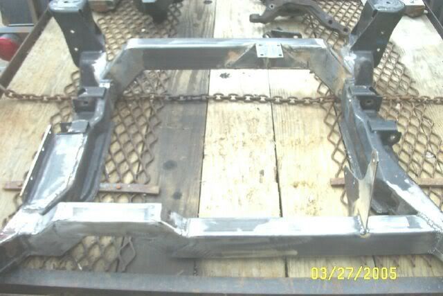
I really like the 2x3x1/8" crossmembers on my SBC car - especially the raised rear crossmember to allow the muffler to lay flat, so this cradle underwent surgery. Here is the operating table - shimmed to make it level in both directions:
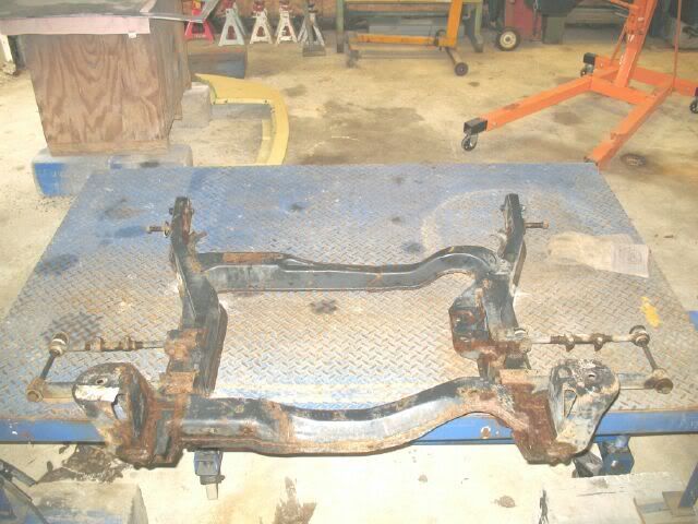
Cradle welded to the table to keep everything level/square:
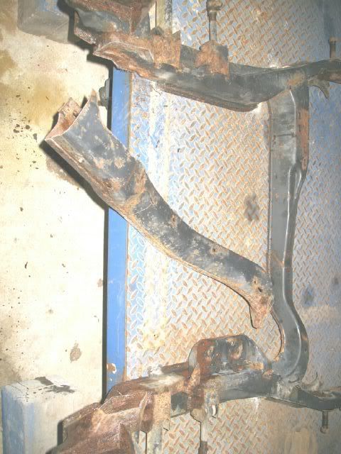
Surgery begins:
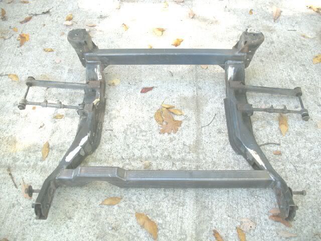
After Surgery 66.5 lbs (4.5 lbs heavier):
IP: Logged
04:41 PM
fieroguru Member
Posts: 12462 From: Champaign, IL Registered: Aug 2003
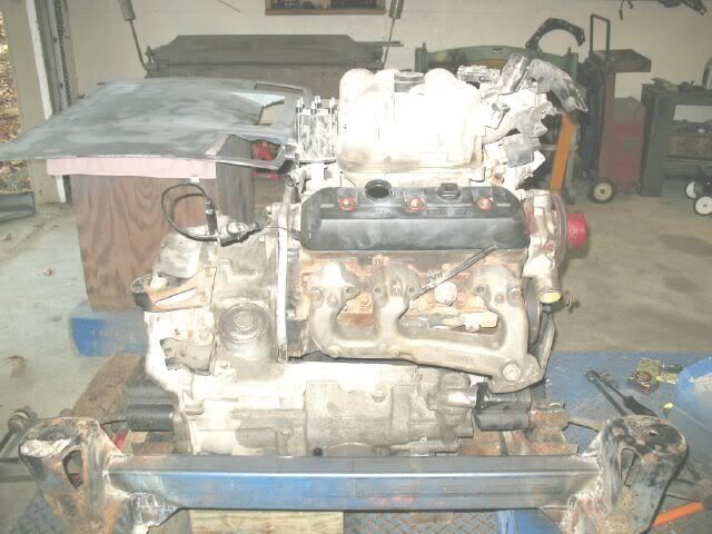
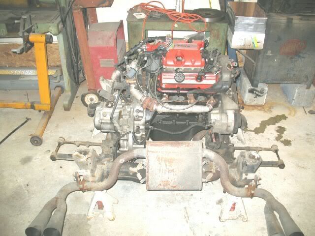
The mock up. The engine/tranny are supported off the table and are not resting on the cradle. This allows the engine/tranny elevation to be set and then temporary mounts made for the first test fit.
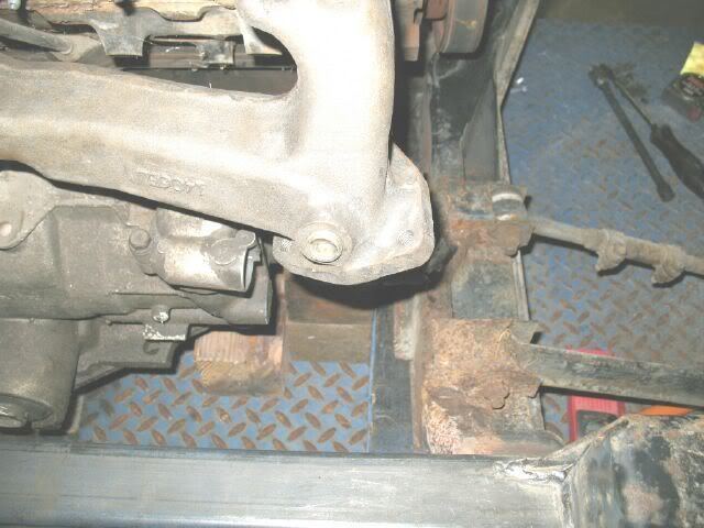
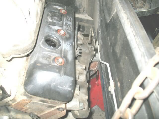
The exhaust manifold in this pic is a left hand S10 version and it clears the end of the tranny and will dump the exhaust down to the pipe coming from the front.
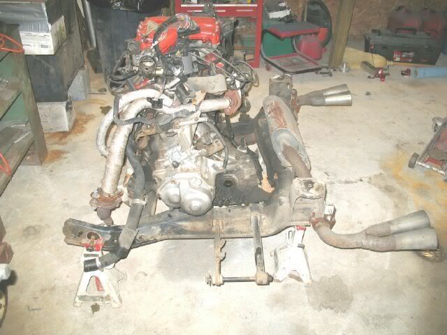
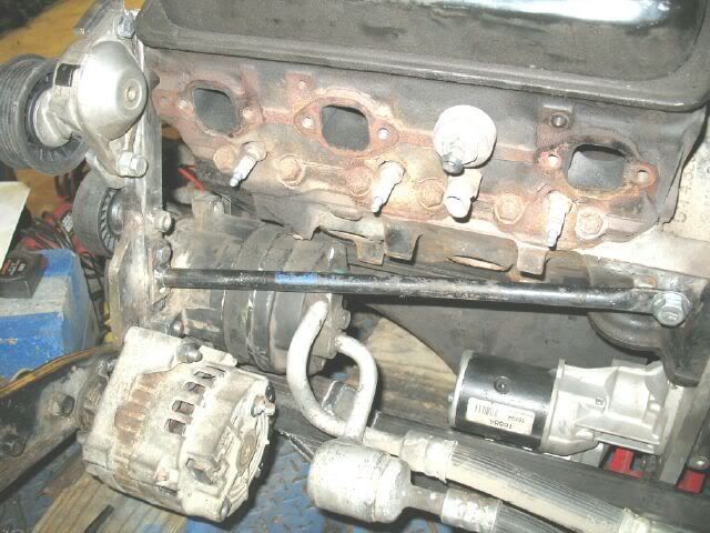
The front side is very busy. The 2x3 front crossmember was located futher forward than the original (it was placed along side the original) so this provides room for the starter solinoid to go down along side the oil pan. This allows the stock van Left side manifold to be retained, but the exhaust pipe will have to bend slightly to clear the new crossmember location. The stock 4 cyliner AC lines get in the way of the exhaust, so they will be reworked. With the starter/solinoid rotated down, there is quite a bit of room for the oil filter relocation - I am crossing my fingers that the stock 4x4 bravada oil filter relocation kit will fit cause I happen to have one of those!
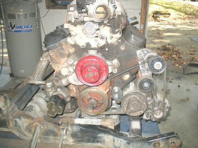
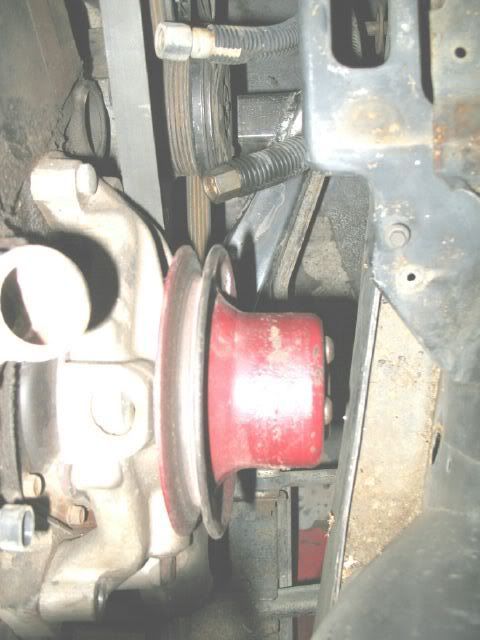
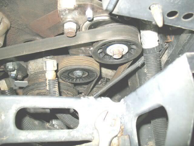
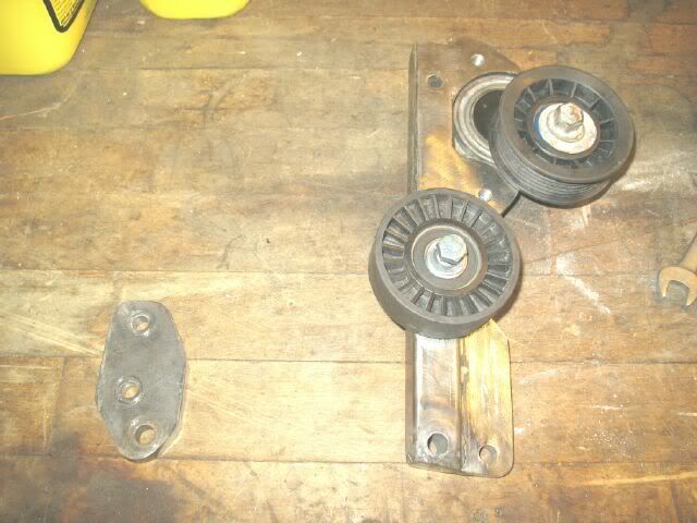
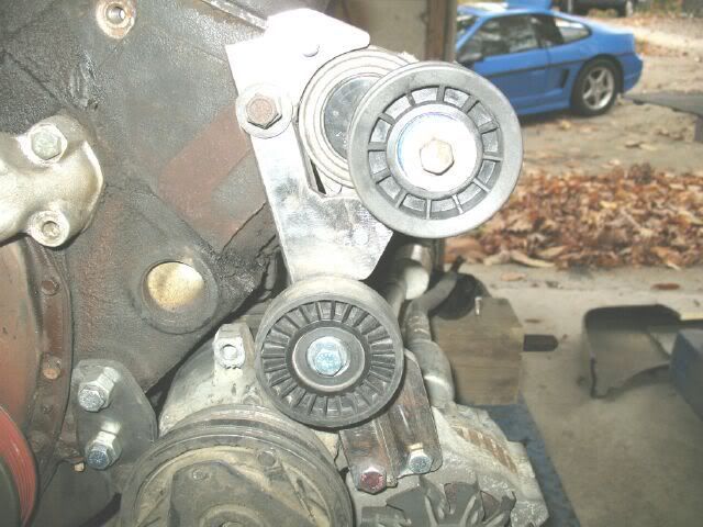
I am very pleased with my accessory drive! It uses the modified 3.1 balancer from a cavalier, the 88 4 cyl alternator and AC compressor (which are also the same as the CPI AC/Alt) and the stock 4 cylider serpentine belt. The tensioner up by the valve cover is a Ford part from the shelf (I have no idea what it is off if) and an idler pulley from autozone. The waterpump (nornal short SBC pump) will be driven with a V belt from a pully mounted to the front of the balancer.
Hopefully in the next week or two I will have the engine in the car for a test fit. The alternator clearance to the firewall, starter and exaust clearance to the crossmember are going to be close and need to be balanced. Then I will work on the mounts.
Anyone happen to have a set of poly bushings for the 88 trailing links (the ones that go front to back)? I have a set of bent up trailing links and plan to use the round ends for my poly engine/tranny mounts
[This message has been edited by fieroguru (edited 10-28-2007).]
IP: Logged
05:30 PM
Russ544 Member
Posts: 2136 From: S.W. Oregon Registered: Jun 2003
do you know any history on that adaptor? is it a one of a kind, or was someone actually making those with a "twist" for some specific application? I don't know what it would gain in a std Fiero, but there must have been some reason for it.
you'll have plenty of room for a serpentine drive and a stock shorty pump. the twin v-belt setup I had left enough room to throw a cat between the frame rail and pulleys.
EDIT: you posted wile I was writing. looks like your alt should (barely) clear, but that tensioner sure looks like it will be placed in the passenger seat. A trick I use is to make a cardboard template that includes the cradle mount holes. that way you can see how much room you have to work with, and where. I assume you're going to use a short v-belt from WP to crank pulley with another idler for adjustment?
lookin good as usual.
Russ544
[This message has been edited by Russ544 (edited 10-28-2007).]
IP: Logged
05:32 PM
fieroguru Member
Posts: 12462 From: Champaign, IL Registered: Aug 2003
do you know any history on that adaptor? is it a one of a kind, or was someone actually making those with a "twist" for some specific application? I don't know what it would gain in a std Fiero, but there must have been some reason for it.
you'll have plenty of room for a serpentine drive and a stock shorty pump. the twin v-belt setup I had left enough room to throw a cat between the frame rail and pulleys.
Russ544
I picked up the adapter kit used so I have no idea who originally made it. The rotation was most likely done to avoid cutting the starter pad off the block on the auto kits and potentially providing more room for valve cover clearance to the passenger deck lid hinge bracket. The street dreams site has a rotated style adapter as well as the conventional one.
This adapter plate is aluminum and made very well. The steel dowel pins are a pressed in from the engine side and have a larger machined lip (about 1 1/2" dia) to keep them from pulling through and provide a very strong connection (steel bolt into steel insert) for 2 of the 5 bolts.
IP: Logged
05:42 PM
Russ544 Member
Posts: 2136 From: S.W. Oregon Registered: Jun 2003
ha ha. you posted over me again (see prior post edit). I didn't have to cut the hinge at all for my 4.3 swap. the vc is short enough to miss it entirely
IP: Logged
05:51 PM
fieroguru Member
Posts: 12462 From: Champaign, IL Registered: Aug 2003
For the upper tensioner, I measured my SBC car from the valve cover to the firewall and should have an inch in that location. This an the alternator will define engine placement front/rear. One of these days I will just hack up an 88 parts car for the basics of the engine bay for mock up purposes.
Yes, I planned to use a short V belt from the water pump pulley to a pulley mounted on the crankshaft. Several years ago I mocked this up with a morroso lower pulley and some stock upper pulley (probably still on the shelf) and came up with a combo that was tight without the need for the idler - had to install the waterpump pulley to install the belt. I would like to run it without the idler, but we will see.
Just like the SBC swap, there are a bunch of areas that clearance must be checked and maintained... just do not have to mess much with the water pump area.
IP: Logged
06:14 PM
Raydar Member
Posts: 41124 From: Carrollton GA. Out in the... country. Registered: Oct 1999
Before I start fabrication on the 4 engine/tranny mounts, I wanted to get the engine in the car with the ability to move it front to back to see how things would fit, and where the engine needed to be mounted. I just grabbed some scrap steel and made some crude mounts (for mock up purposes only) that rest on top of the 2x3 cross members and allow movement front to back/side to side.
Now that I am ready for the first test fit, the old 2.8 must go. It is a tired 86 2.8 with low oil pressure with isuzu 5 speed.
I have all the top side items disconnected and should have the engine out and the 4.3 in for test fit this weekend.
IP: Logged
12:09 PM
blackrams Member
Posts: 32794 From: Covington, TN, USA Registered: Feb 2003
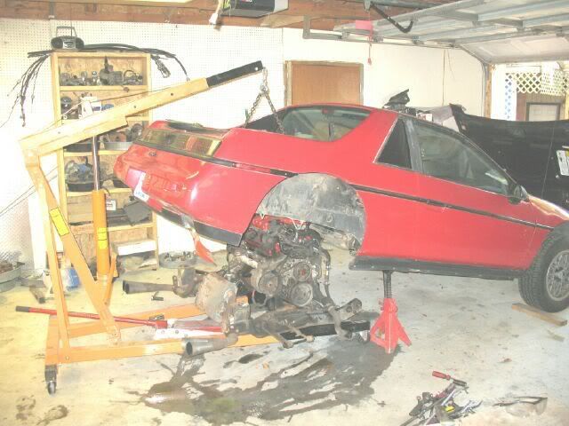
Here is how I remove the engine/cradle when I am not around my lift. Get everything disconnected and loosen the front/rear cradle bolts, slide cherry picker under the cradle and lower the car down on the legs, then remove the last 4 bolts and raise the car up in the air with the boom, install jackstands (and front wheel chocks) and give the car multiple shoves while still attached to the cherry picker to make sure they will stay put. Lower the ram and pull cherry picker with engine/tranny/cradle out from under the car. Do not spend any time under the car with it jacked up in this manner - lower it back down to level to do any work under the car.
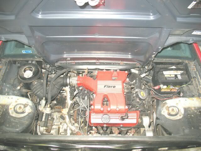
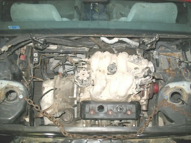
Junkie engine
Here is the 4.3 getting comfy in its new home! It fits quite well with the only tight spot being the throttle body to the decklid hinge... it will need a slight notch. I have not played with moving the engine into the perfect position, but right now there is atleast 1-2" around everything so I am quite please.... and tired.
That is it for today!
[This message has been edited by fieroguru (edited 11-03-2007).]
You do plan on cleaning and painting up that motor and tranny before install right? If you don't, you will regret it. You'll want to show off your install and it wont look as appealing.
I have a set of red poly mounts for the trailing links for an 88. PM me
[This message has been edited by bonzo (edited 11-03-2007).]
IP: Logged
08:57 PM
Nov 4th, 2007
fieroguru Member
Posts: 12462 From: Champaign, IL Registered: Aug 2003
i think you may have some squealing and slippage problems with your ac. you dont have much belt wrap at all. just something to think about
The belt wraps about 25 to 30% of the pulley and uses a 6 rib belt, so it has about the same amount of wrap as an LS4 setup, slightly more than the ecotec and significanlty more than a SBC/fiero v-belt combo. I am not expecting any issues with belt squealing.
IP: Logged
06:19 AM
fieroguru Member
Posts: 12462 From: Champaign, IL Registered: Aug 2003
You do plan on cleaning and painting up that motor and tranny before install right? If you don't, you will regret it. You'll want to show off your install and it wont look as appealing.
I have a set of red poly mounts for the trailing links for an 88. PM me
I do plan on cleaning the engine and doing some painting of the engine bay and select engine parts. I also plan to run the wires/hoses in descrete locations (to a certain level - not taking the time to relocate the 500) and do what I can to eliminater clutter and keep it clean.
Understand this is only phase 1 - get it in and running and make sure I am happy with it. Once I am happy with the swap/performance/auto I will pull it again to do performance upgrades and refine the cosmetics. If I do not like it, it will be yanked within a year and something else installed, so I do not want to invest a great deal of time/effort/$$$ into this until I know I like the setup.
PM returned.
[This message has been edited by fieroguru (edited 11-04-2007).]
IP: Logged
06:36 AM
Nov 11th, 2007
fieroguru Member
Posts: 12462 From: Champaign, IL Registered: Aug 2003
Good thread! You should like this motor. 195HP and 260 lbs of torque in stock form. It moves my 1994 S10 around quite well and it weighs at least a 1,000 pounds more. I've never had my belt on the S10 squeal. I rarely have to work on the S10, so I'm unsure if yours is in the stock location! Keep me posted so that I'll know what to do with the S10 motor should the truck ever get totaled. Also, would you mind posting the new dimensions of your frame so that the next person (me?) might save themselves a few headaches! Thanks!
IP: Logged
10:25 AM
vortecfiero Member
Posts: 996 From: Toronto Area, Canada Registered: Feb 2002
been there done that lol you will love the 2nd gear launches with all that torque
my first setup
I love what you did with the serpintine belt and your mounts !
------------------
87 Fiero GT 5sp with Vortec L35 4300 Turbocharged V6 Bully Stage 2 clutch Syclone intake manifold and engine management with Moates adapter and chip burner Air/water intercooler and Devil's Own progressive water/alky injection 50lb injectors, 3 bar map sensor, Walboro fuel pump and Jabasco Intercooler pump LM1 wideband on custom manifolds and 3" stainless exhaust system T31/T04B S4 turbo with a Super T61 in the box S10 caliper conversion. Murphy's Constant Matter will be damaged in direct proportion to its value Murphy's Law of Thermodynamics Things get worse under pressure. Arthur C. Clarke "Any significantly advanced technology is indistinguishable from magic"
IP: Logged
12:39 PM
vortecfiero Member
Posts: 996 From: Toronto Area, Canada Registered: Feb 2002
just noticed the balancer you are using... is it from an externally balanced engine (like the 4.3) ? and did it fit the crank with out mods ?
I have been told that since the crank is so short, compared to a V8, it doesn't need a typical harmonic balancer and can actually go with out one. I use one because GM put one there lol
IP: Logged
06:49 PM
fieroguru Member
Posts: 12462 From: Champaign, IL Registered: Aug 2003
I was quite pleased with the test fit and determining the engine location front to rear, so out it came again. Since now I know it fits, it is time to share some more details.
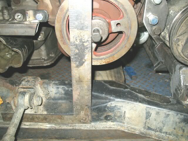
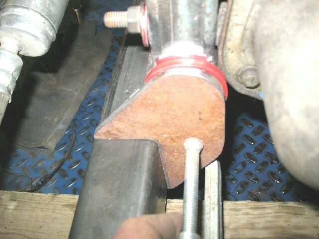
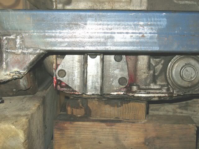
The engine location front to rear is 14 13/16" from the centerline of the front cradle bolts. This measurement is taken level, not center of hole to center of crank (at an angle). In the pic below, I scribed the cradle for centerline of the 2.5 and the square is sitting at the 2.5 scribe mark. The 4.3 is mounted about 5/16" forward from the mount location of the 2.5. The crankshaft is also 8 7/16" from the bottom of the cradle. The engine is level right to left, but angled down slightly to the front.
The engine can not go any lower with this automatic since the pan is flush with the bottom of the cradle as well as the engine oil pan. A manual tranny and shallower oil pan would allow the engine to sit lower (like my SBC) but the bottom AC compressor bolt boss is within 1/4" of the crossmember so lowering the engine would cause some other complications.
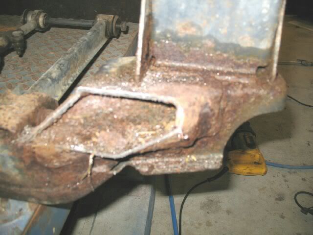
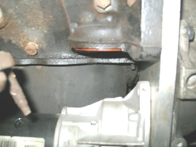
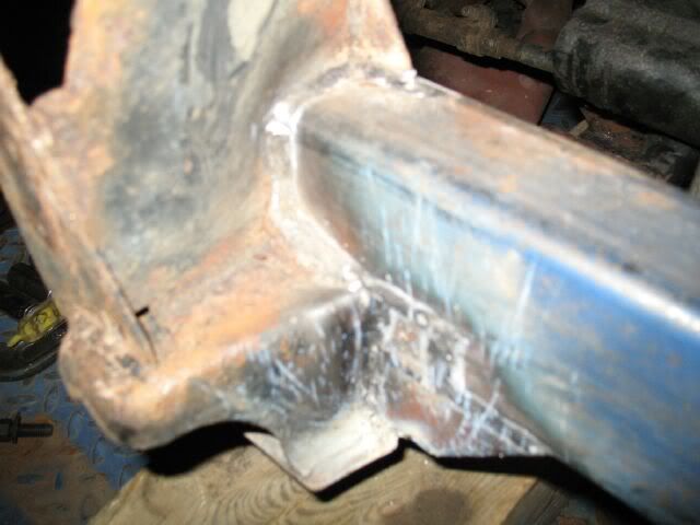
With the engine in the locations above, here is the exhaust clearance to the front crossmember. It will require a bend coming out, but is quite doable:
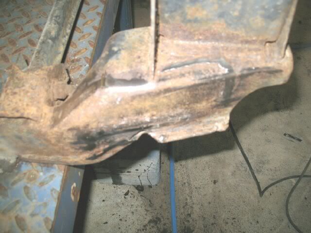
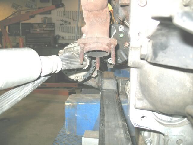
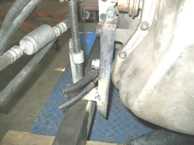
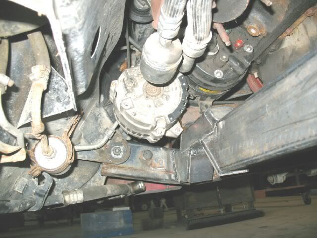
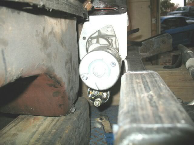
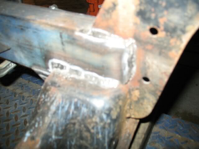
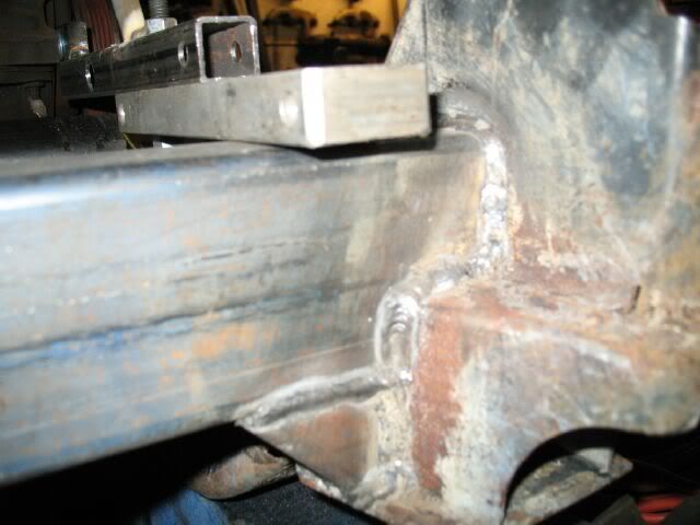
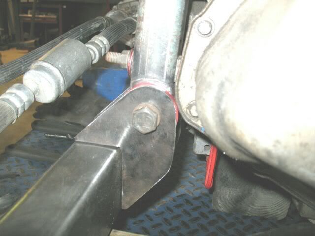
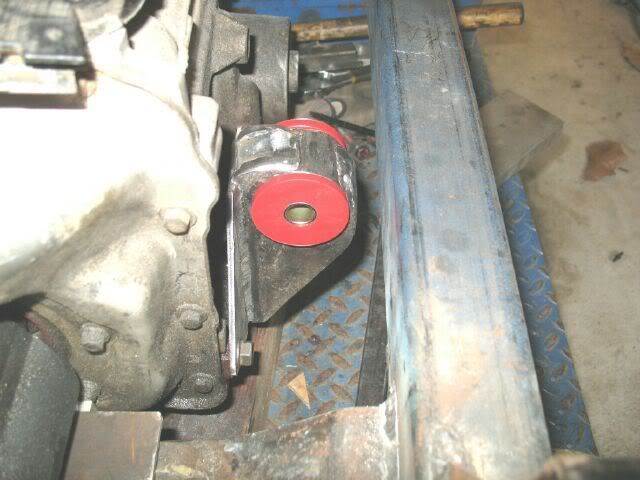
Here is the starter clearance. I will have to drill and tap holes in the adapter plate to run the starter rotated in this location with the solenoid down low. There is no way you could do this with the stock crossmembers. I do need to clearance the corner of the adapter plate to the crossmember (it is only 1/8" right now).
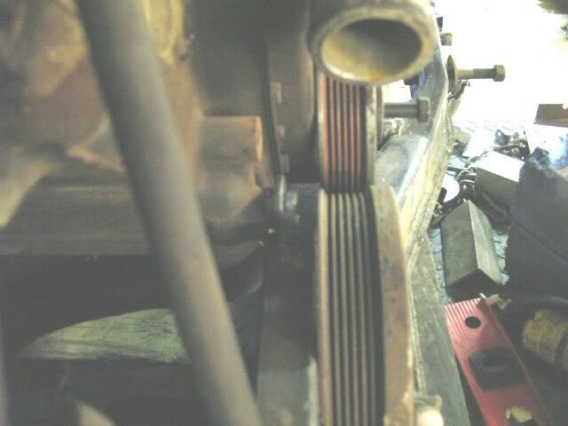
The balancer protrudes from the face of the 4.3 by 2 1/4". You can see I still need to shorten the timing tab.
quote
Originally posted by vortecfiero: I love what you did with the serpintine belt and your mounts !
Thanks!
One of the main features of this swap is the serpentine setup, so here are a few more pics of it. On the left of the first pic is a 3/8" thick bracket that bolts to the front of the block and one of the AC tabs bolts to it. On the right is the main accessory bracket. It backbone is a 1x1 steel tube. At the top it attaches to the head (tube drilled and 3/8" threaded coupler welded in tube then drilled to allow the 3/8" bolt to pass through. The bottom bolt is for the AC compressor. It to had a 3/8" threaded coupler welded in and drilled to allow the metric AC bolt to pass through. In the center the idler pulley is also supported on a 3/8" threaded coupler welded into the tube. The Tensioner at the top is a Ford unit (unknown application) with the proper ribbed pulley. There are 3/8" thick tabs welded to the side to attach the tensioner. The other 3/8" thick lower tab is for the alternator - again it was welded to the tube on both sides.
Here is a closer view of the front side (ignore my longer bolts and washer/nuts for mock up):
Here is the back side. Notice the stabilizer bar from the back side of the bracket to the far end of the block. It clears both the AC compressor and the manifold (but not by more than 1/8").
To this accessory bracket took 3 failed attempts and about 2 weeks of work (nights and weekends) while my wife and daughter were out of town visiting relatives. Now if someone would just CNC one out of solid aluminum for me!
quote
Originally posted by carnut122: Good thread! ....... Also, would you mind posting the new dimensions of your frame so that the next person (me?) might save themselves a few headaches! Thanks!
Thanks!
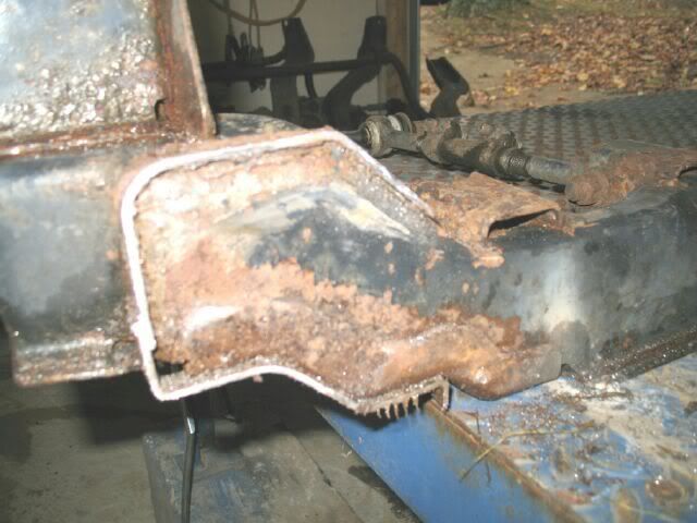
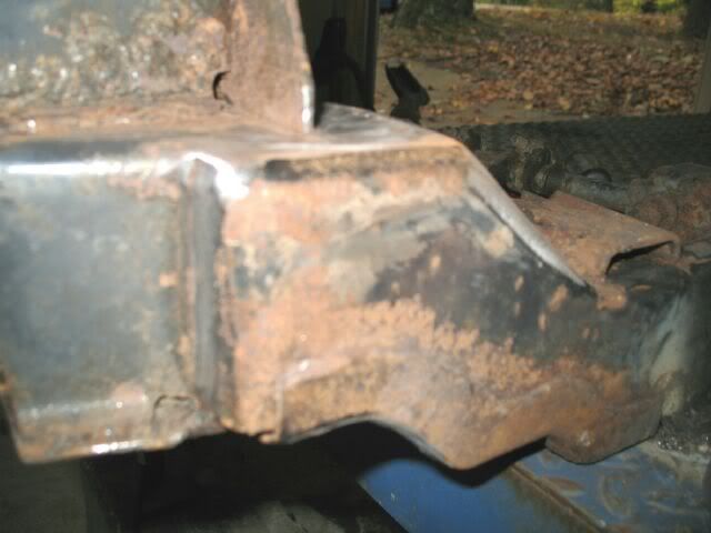
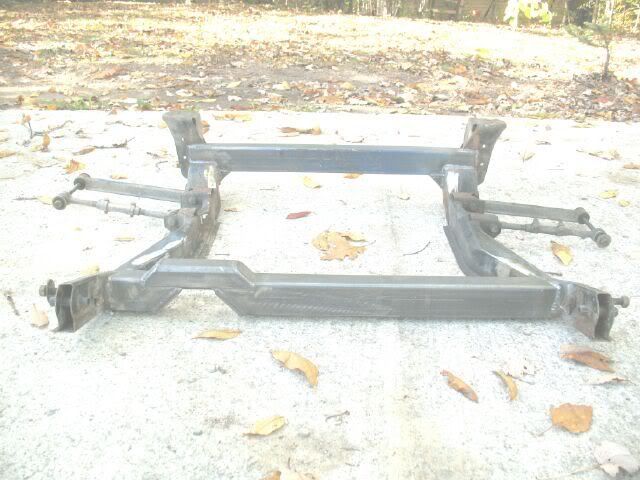
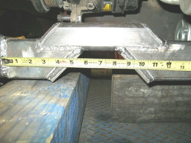
The front crossmember is 5 1/4" from the centerline of the front cradle bolts to the front edge of the 2x3 crossmember (so the back edge is 7 1/4" from the front cradle bolts). This crossmember is also 36 1/4" wide (88 - so 84-87 could be different). Here is a pic of the front notch for the exhaust. The opening is 2 1/4" from the bottom, the tube on top is 2x2x1/4" steel and the angle plates are 2x3/8" bar stock. Most of the 4lbs of extra weight is right here! Here is a pic with a tape to get the general dimensions:
The front edge of the rear crossmember is 31 3/8" from the center of the front cradle bolts. The rear crossmember is also raised 4 1/4". There is about 24 1/4" of room between the front and rear crossmembers. The rear crossmember is 35 1/2" long and was notched to fit around the rear cradle mounts and the contours of the rear of the cradle. There are also some small "V" sections to help ensure as much rigidity in this rear section as possible.
The new crossmember is about 3/8" in front of the rear sway bar brackets. There will be a rear sway bar on this car, but I will probably have to space out the brackets about 1/4" to clear the new crossmember.
For comparison, here is the cradle in my SBC car (engine/trans solid mounted)
There is room for all 4 corner engine/trans mounts to be on the inside of the new crossmembers. I have 3/16" steel plate to fabricate the brackets from, so that very well count be the next update.
Anyone have a 4 cly thottle cable for cheap?
IP: Logged
07:31 PM
PFF
System Bot
fieroguru Member
Posts: 12462 From: Champaign, IL Registered: Aug 2003
just noticed the balancer you are using... is it from an externally balanced engine (like the 4.3) ? and did it fit the crank with out mods ?
I have been told that since the crank is so short, compared to a V8, it doesn't need a typical harmonic balancer and can actually go with out one. I use one because GM put one there lol
The balancer is from a 3.1 from an early 90's cavalier. Mods to the balancer include: turned 1/4" off the front face of the balancer to reduce the overall thickness of the balancer (and to remove weight!), extended the seal surface on the backside to allow the balancer to suck up tight to the timing cover and used some emry cloth on the inside to help it go on (it was a snug fit). Here is a unmodified balancer next to this one:
It is from an internally balanced engine. While the 4.3 is an externally balanced engine, the balancer is neutral balance with the only external balance being on the flexplate/flywheel. Here is a pic of the 4.3 balancer (on the left):
I have known many stock car guys to delete the balancer on their race SBC's and only run the center hub (press the outer ring off. Also, the balancer (or should it just be a pulley) on the right is from a 2.5 and is OEM free from any damper. Maybe the theory of the shorter cranks not needing the dampner has some merit. This one is a 6 rib and also is compatible with the SBC/4.3 crank snout. I had it on a SBC for mock up several years ago, so it could be made to work as well.
IP: Logged
07:56 PM
Nov 12th, 2007
vortecfiero Member
Posts: 996 From: Toronto Area, Canada Registered: Feb 2002
i keep coming back to this post lol make sure you upgrade the fuel pump.. the CPI is set for 60 psi not running and about 50 psi when its running (the vacuum reference is a small hole in the cap of the regulator in the center of the manifold I used a walbro and i put the foam rubber sound insulation on it as they are really noisy.
here is what im starting my belt setup with (I had a dual v belt first)
IP: Logged
06:25 PM
Nov 20th, 2007
fieroguru Member
Posts: 12462 From: Champaign, IL Registered: Aug 2003
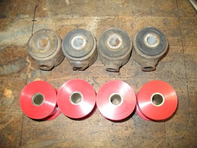
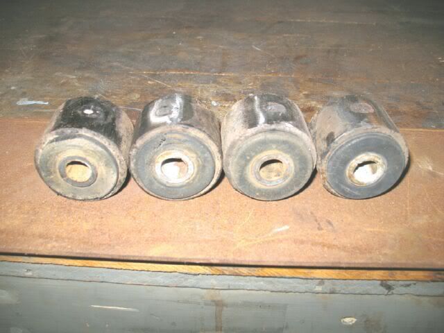
Not much progress to report. Here are the ends of the trailing links that will be made into engine/tranny mounts and the poly bushings from Bonzo.
I also scored an 88 rear sway bar for the car from Blackrams.
Other than that, I did a lot of yard work to pull the bravada onto concrete in preperation of pulling the 4.3 and fuel tank for the fuel pump (new 2 years ago). I looked under it and can not even see the oil filter relocation adapter because the diff is in the way. Maybe after the holiday I will get the engine pulled.
[This message has been edited by fieroguru (edited 11-20-2007).]
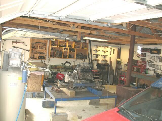
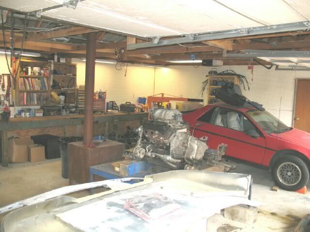
After spending 3 days dedicated to the holiday travels, I was able to get back to the swap today. First order of business was to clean up the garage.
Here is my little helper.
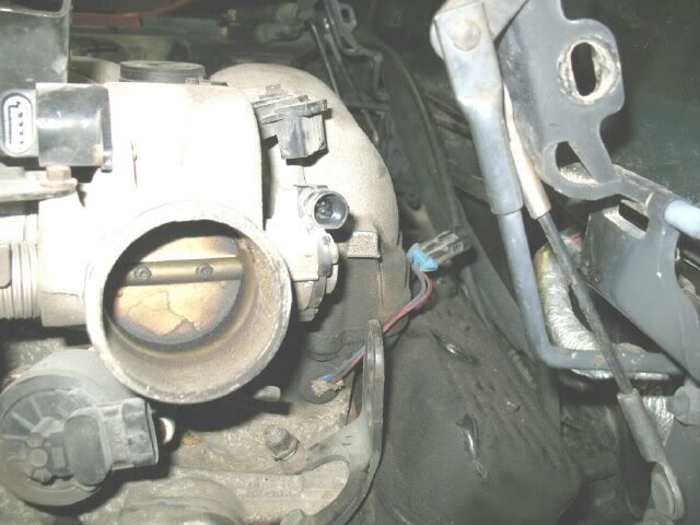
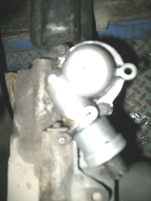
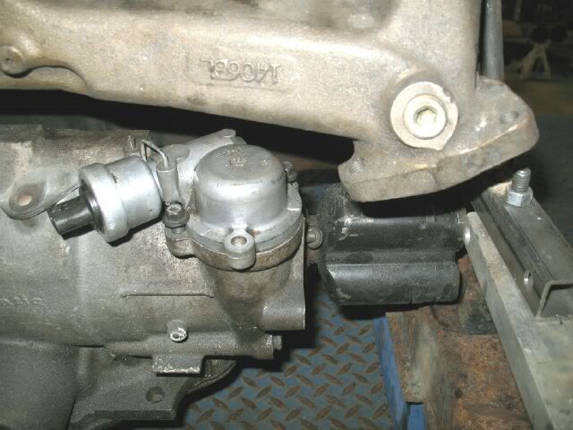
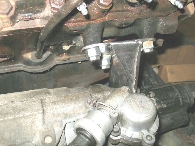
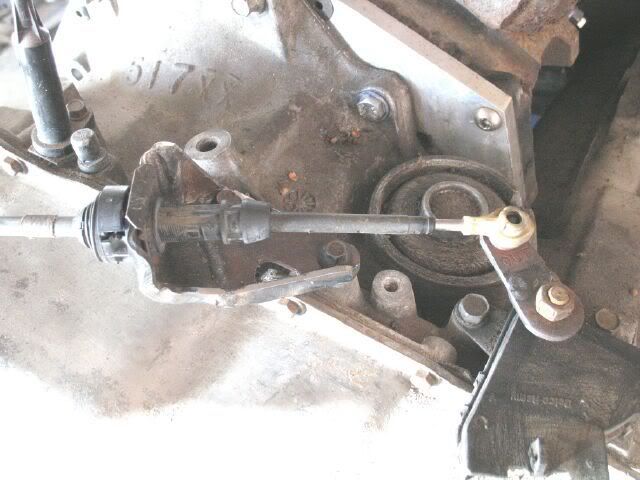
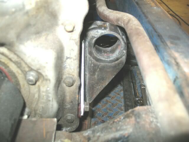
Next order of business was to rotate the VSS housing to clear the exhaust. It was easy to rotate (without the bolts), but then the bolt tabs would no longer line up. The head of the bolts overlapped the cover without the mounting tabs, so that is how they it is attached now. I did have to cut one of the original mounting tabs off and do some careful clearancing. Once rotated, I installed a Fiero VSS.
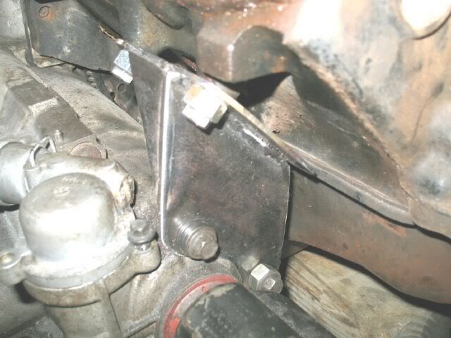
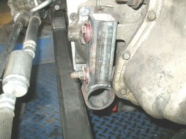
Before getting to the engine/tranny mounts, I decided to make the bracket to connect the snout of the tranny to the engine. It is made of 3 pieces of 1/8" steel plate and welded together.
I took out the grinder and cleaned up the round ends for the mounts.
That is about all I got done today...
[This message has been edited by fieroguru (edited 11-25-2007).]
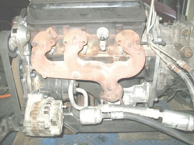
Hi fieroguru and thanks. I am at almost exactly the same point as you on my own 4.3 swap and you just saved me from an overlooked mistake! I completely forgot about building the trans mount on the snout (as you put it). That will be my next order of business. I also have one question: Did you rotate the VSS pickup just to clear the exhaust or is there an additional reason? I am using a manifold from a Silverrado instead of an S10 and it seems to clear the pickup pretty well. From what I can tell from the pictures at the beginning of this thread, the S10 manifold looks as though it leans down farther than the Silverrado. Thanks, Egor
------------------ ____________________________________________ "Of all the things I have lost during my lifetime, I miss my mind the most."
IP: Logged
06:47 PM
fieroguru Member
Posts: 12462 From: Champaign, IL Registered: Aug 2003
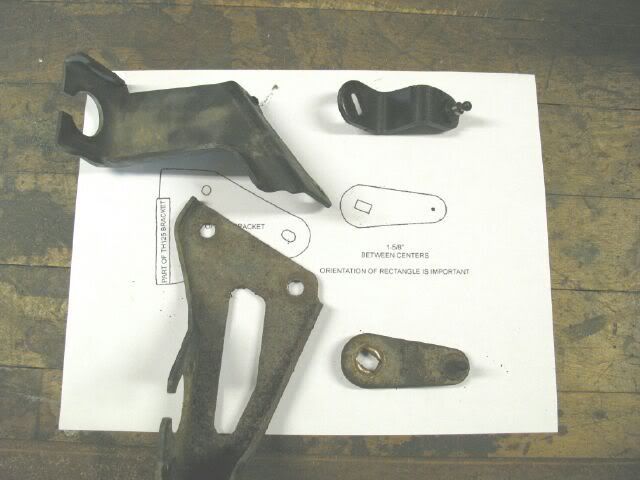
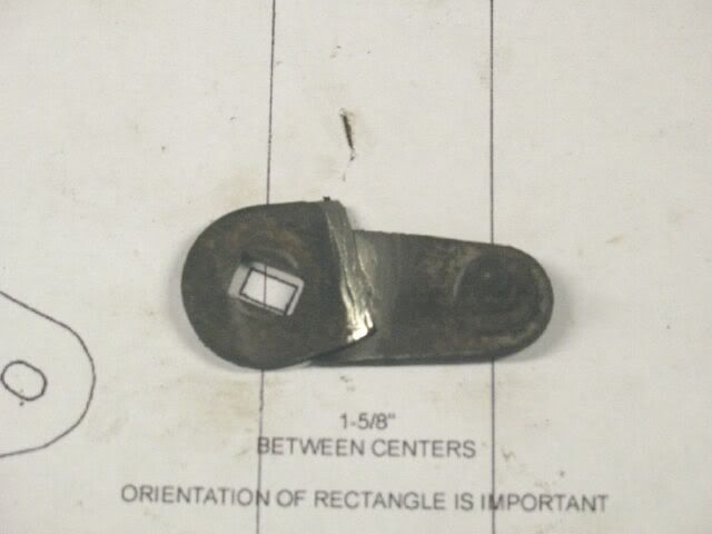
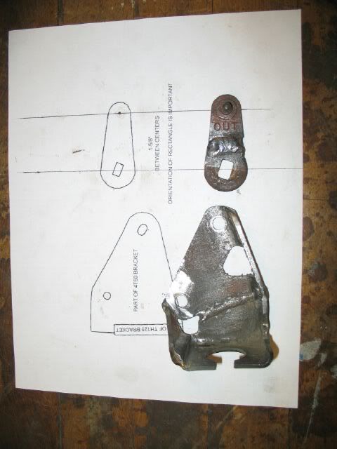
This morning I modified the shifter linkage/brackets on the 4 speed auto to work in a Fiero. I printed out the sketches from fieroaddiction. The 125C parts are at the top and the 4T60 parts at the bottom:
Mock up of the modified shift bracket:
Shift bracket and shift cable bracket welded in the new configuration:
Installed and tested - works great!
Gotta go get more welding wire to start on the engine/tranny brackets.
IP: Logged
01:06 PM
ron768 Member
Posts: 781 From: Somewhere in the southeast Registered: Apr 2004
I have been looking at this since you started, I must say that your welds are beautiful. Your fabrication of brackets and mounts are nothing short of fantastic. It always seemed to me that the 4.3 V6 would have been a natural factory engine for the Fiero. Good HP, excellent torque, good gas milage.
IP: Logged
02:55 PM
PFF
System Bot
Russ544 Member
Posts: 2136 From: S.W. Oregon Registered: Jun 2003
It always seemed to me that the 4.3 V6 would have been a natural factory engine for the Fiero. Good HP, excellent torque, good gas milage.
Well.... two out of three ain't bad . I got ~15 mpg with mine, but then... it did have a lumpy cam etc. the 4.3 is a very "natural" fit for the Fiero however, and Guru has the tallent to make it all work.
Russ544
IP: Logged
04:04 PM
fieroguru Member
Posts: 12462 From: Champaign, IL Registered: Aug 2003
The 4.3 in my Bravada could get 23 mpg at 75 on the highway pushing a brick with AWD. I am shooting for 25-27 mpg on the highway. With the auto, I have the option of getting a more highway friendly final drive to keep the cruise rpms down, so there could be some experimenting once it is running.
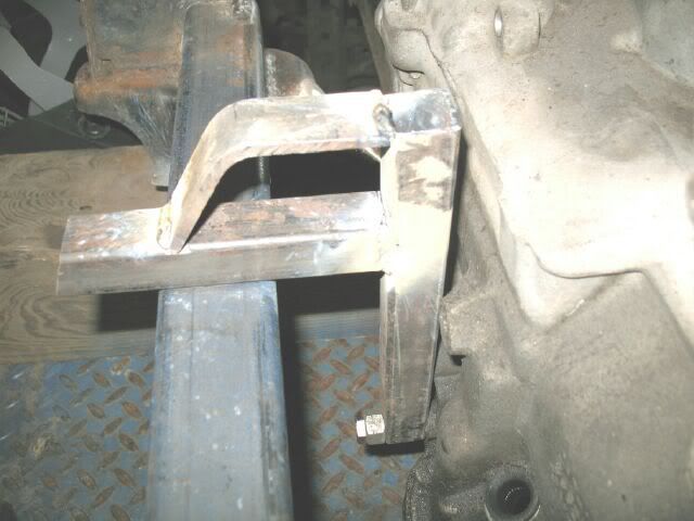
Well I think 1 tranny mount is done... will know for sure once they are all done.
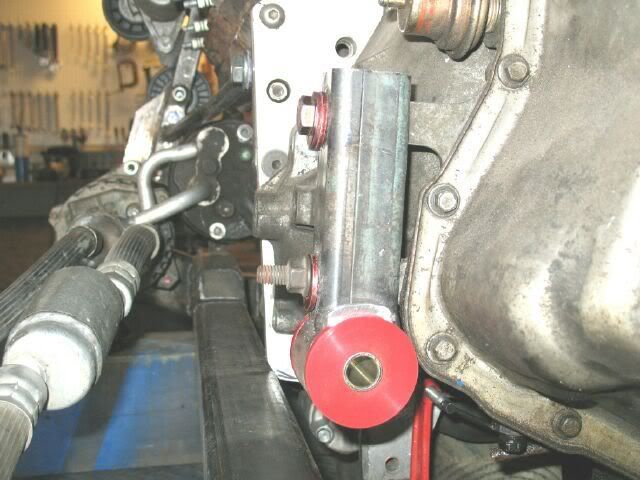
The bracket for the tranny is 3/16" wall tubing. It was drilled for the two mounting holes and a crush sleeve welded in. Then the round end link was welded on (with the rubber bushing still in). After welding, the rubber bushing just poped right out.
More cardboard templating:
Trace out the shape on 1/8" steel plate (duckheads):
Cut them out, clamp them together and clean up all the edges.
Set in place and use a large drill bit through the hole in the bushing to mark the needed hole in the brackets. Drill and clean all the surface rust off the pieces and put back in place (forgive my mock up bolts/washers).
The placement of the engine front to rear is set, but since I do not have my axles yet, the side to side placement is still variable. I will mock up all the mounts, but not tack weld them until I get my axles and finalize the side to side placement.
Hopefully Sunday will be a productive day and I can get a couple more mounts made.
IP: Logged
04:55 PM
Mr.PBody Member
Posts: 3172 From: Cincinnati, Ohio, USA Registered: Oct 2006
Have you considered wiring it for the 749 ECM that controlled the Syclone and Typhoon to keep your options open since little if any tuning would be required to take advantage of it? You could run it naturally aspirated with that code and I have always enjoyed the absence of a MAF sensor after having replaced a few with the aftermarket garbage out there. If you use a MAF sensor get an OE new, used or remaned original. One aftermarket model I was given by a major parts supplier in place of my lifetime warranted BOSCH unit had a common Radio Shack resistor soldered in where the burn off wire that measured air density was supposed to be. I had to make the retailer replace it with another BOSCH unit. It was the way the car performed that made me look harder at the sensor. It never tripped the SES light.
Nice work, be sure to put a 3.33 ratio in that 4 spd and a 2200 stall converter tied into wide tires. Don't forget the neck brace.
IP: Logged
08:33 AM
James Bondo Member
Posts: 264 From: Ontario, Canada Registered: Nov 2003
Originally posted by Joseph Upson: Have you considered wiring it for the 749 ECM that controlled the Syclone and Typhoon to keep your options open since little if any tuning would be required to take advantage of it?
I have not really thought about the ecm side yet, but I have 2 CPI ecm's (can't rememember the # and too lazy to look) and will probably stick with them for now. To convert to the 749 would probably just be a pin swap on the ecm connectors and maybe a few other changes, but at the end of the day, I have no intentions of making this car a screamer (that is what my SBC car is for, and if somthing was going to get a turbo it would be that car).
IP: Logged
02:13 PM
fieroguru Member
Posts: 12462 From: Champaign, IL Registered: Aug 2003
Progress has been slow today, but I did get another mount almost done.
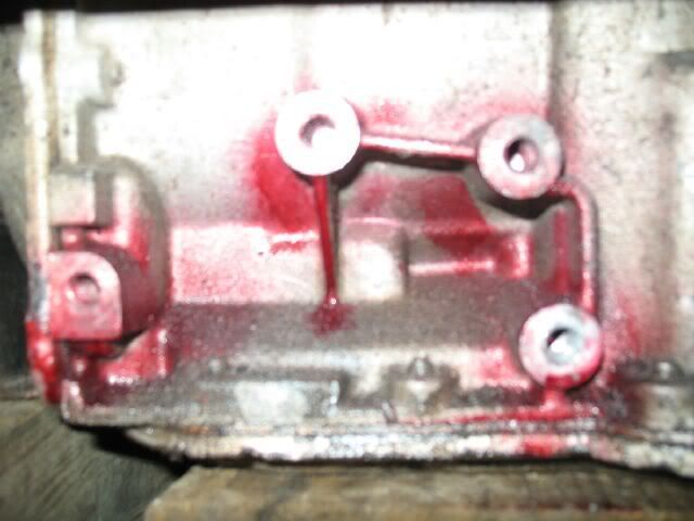
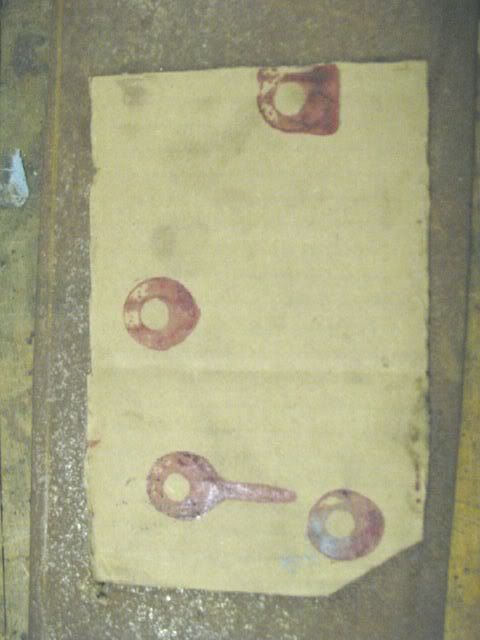
The rear tranny mount uses 4 holes on the backside of the transmission, so first order of business was getting the hole pattern on 1/8" steel plate. So I sprayed hightack gasket sealer over the 4 bolt holes that the rear tranny mount will utilize, and placed a piece of cardboard on them to transfer the holes to it.
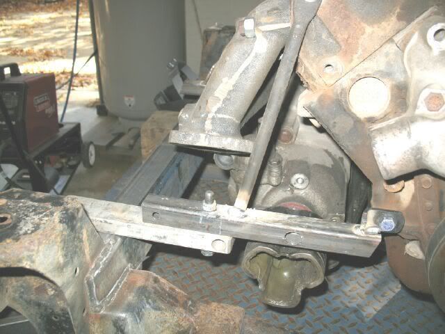
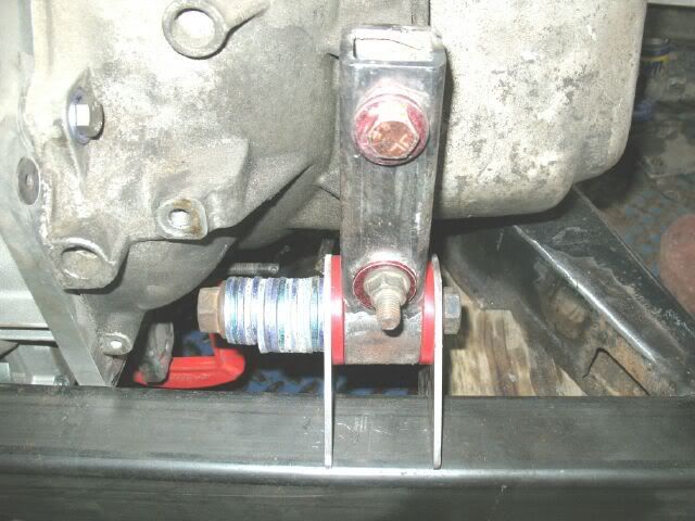
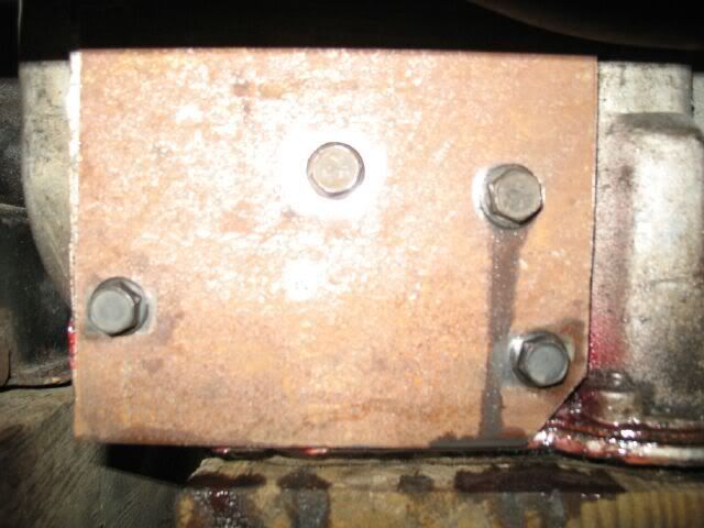
This rear mount needed to be as high as possible to maximize the room for the muffler that will lay flat under the rear crossmember. It also had to clear the rear sway bar and acess to all 4 bolts needed to be retained. This is how it turned out (sway bar ends are down almost to the bottom of the cradle, so there will be plenty of clearance at ride height):
I still need to make the parts that will weld to the crossmember. I am going to make them so they will go over the top of the crossmember as well along the side. This will allow them to hold the engine/tranny weight while just sitting in place. When them mounts get final welded to the crossmembers, this top portion will be cut back off (the sway bar will not fit with them there, unless I move it up like on my other 88).
[This message has been edited by fieroguru (edited 12-02-2007).]