I'm glad Roger has his site up. I've bought his parts and they are top notch.
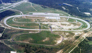
I've been to an x-cross in Houston and a two day drivers education school at Texas World Speedway since the last time I updated this thread.
I updated the four banger with adco bars fore & aft, brake job and new koni shocks up front and took it racing. I'll post that stuff on another thread when I get the photos back. I'm keeping notes as the car progresses into a full blown track car and will post my opinions on relative merit of the mods performed.
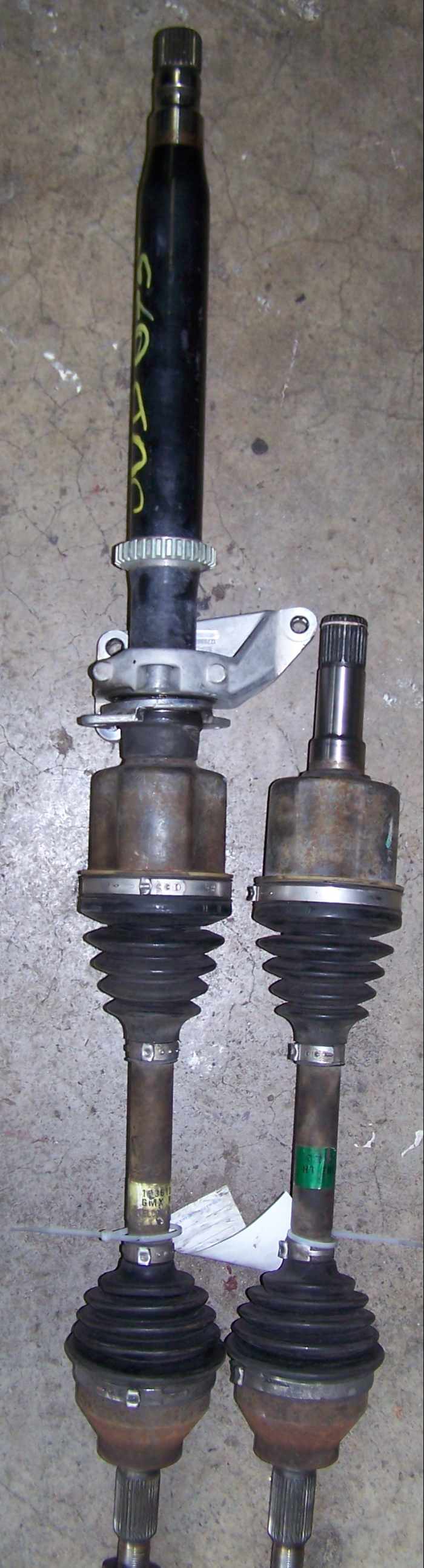
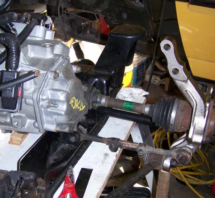
I got the remaining cobolt axles finally. The left (yellow tag) and right (green tag) axles are the same length.
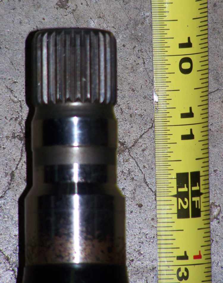
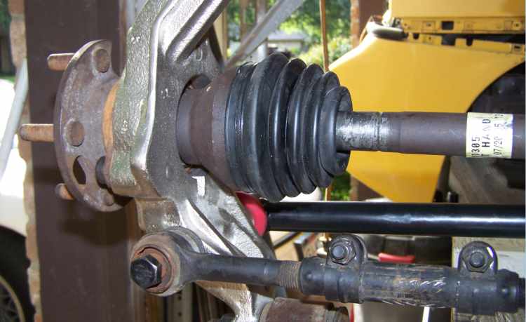
The intermediate shaft stub details. I think this is the same for the 6 speed.
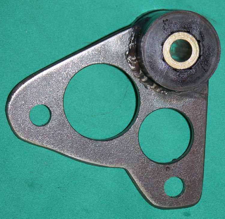
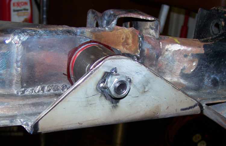
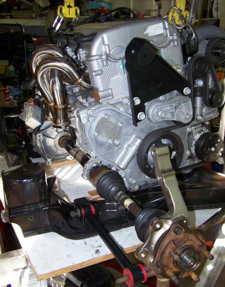
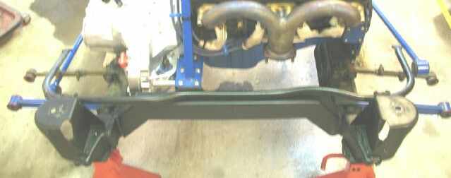
I mocked up the suspension with the cobolt axles and fiero hubs and centered the engine. This view shows Roger Thelin's torque strut mount plate on the ecotec and the top part of the headers mounted. The cobolt's track is about an inch narrower the the fiero so there is about 1/2" of slop that each cup will take up. The outboard CV joint does not have the dust shield the fiero ones do but I can live with it.
I spent the entire time on the recipient host chassis prepairing for the track then this engine/cradle in the last three weeks so progress will be slow for the next few weeks as time allows.
Thanks for every bodies comments.
------------------ yellow 88 GT, not stock white 88 notchie, 4 banger
looks like a simple solution to everyones 6 speed axle problems .also it means i could easily adapt an f35 to my 2.2 setup .great work ,your pictures are awesome .
Not the thread jack but this is the thread that I got the most responses from
I got the alternator to turn on, I orginally tested it using 4 1.5v batteries and then after it turned on, I got a little device that converts 12volts into a few different volt setttings, not 5 volts tho, but 4.5 turns it on. The problem: Im not sure how many amps I am getting out of it. It seems slow to respond. It dips under 13 volts when I turn the fan on or hit the lights up. With the flashers on it goes between 13.3 and 13.8. Charges at 13.75 according to Megasquirt. Anybody else have any comments on that?
Maybe the DC signal is freaking the regulator controls out? You said that it was suppposed to see a pulse-width modulated signal btween 15-87% duty cycle, correct? If you feed it pure DC, it may not know how to handle a 100% duty cycle signal and might be reverting to some failsafe power output.
556 timers are your friend.
[This message has been edited by AP2k (edited 06-21-2007).]
Maybe the DC signal is freaking the regulator controls out? You said that it was suppposed to see a pulse-width modulated signal btween 15-87% duty cycle, correct? If you feed it pure DC, it may not know how to handle a 100% duty cycle signal and might be reverting to some failsafe power output.
556 timers are your friend.
There are 3 wires to the alternator, 1 goes to the battery wire A: is the alternator turn on which requires 5 volts, thats what I have 4.5 going to and its turned on. wire B: looks for the wave signal, I have nothing hooked to that.
The Pin 1(orange for the L61) If held at 5V will default the generator to 13.8V. It thinks your shorted to B+, it'll run your car and charge your battery but it not going to give you all it's got.
There is a lot going on between the BCM (body control module) and ECM (engine control module). The BCM monitors the battery and controls the alternator unless the ECM overides for
engine cooling fans are on high speed high fuel demand calc ambient air temp is less then 32 Deg F.
There could be a very cool little black box if somebodies good with PWM circuits.
Here's the goods to make the generator do its thing all the way.
The L-termanal control signal is a 5 Volt pulse with modulated (PWM) signal of 128Hz with a duty cycle of 0-100%. Normal duty cycle is 5-95%. The either extremes are for diagnostics purposes.
The following table shows command duty cycle and output voltage of generator. 0%______0V 10%_____11V 20%_____11.56V 30%_____12.12V 40%_____12.68V 50%_____13.25V 60%_____13.81V 70%_____14.37V 80%_____14.94V 90%_____15.5V 100%____13.8V
As you can see you could make a Dail-O-Voltage box with this data, if your real good with some programing you can combine timers with inputs so you boost idle voltage when the a/c comes on or just after it cranks for 20 seconds like the factory does.
Some stand alone efi controllors have programable PWM outputs just for stuff like this.
------------------ yellow 88 GT, not stock white 88 notchie, 4 banger
Not gonna be very helpful here, but I am going to say, congrats on getting a hold of this powertrain. It's the same swap I'm hoping to complete down the line, but every time I attempt to get my hands on a parts car, something comes up on the seller's end to where I can't seem to get my hands on one. Good luck with the swap.
Are you planning on installing GM's stage 2 upgrade kit into this motor? Or are you going to leave it at the stock 205 hp/200 tq rating?
Also - what is the significance of the lack of the outboard CV-joint dust shield? Will that leave a drop in overall reliability? Or is it an inconsequential little thing?
[This message has been edited by Ravant (edited 06-22-2007).]
I found this drop out on www.used-parts.com but if I were to do it again using the stock ECU/BCU & harness I would get the whole car and pull the parts myself.
If you buy on the internet, you may get something shipped from another dismantler then the one you sent your money to. Warrenty issuse are PITA! These are parts from wrecked cars after all. I'm still waiting on the correct replacement transmission 2 months later. The sent me an F23 rather then the F35. (long story)
On engine upgrades, Yes please! The intended purpose of the car is to take it to the track a lot. After seeing a stock SS cobolt at a x-cross event I can see the need for more rpm's or a steaper gear. In 2nd he would hit the rev limiter and in 3rd it sounded like it was just under the sweat spot. The stage 2 & 3 mods adds power were it's needed. I promised myself I would get an award with engine upgrades after I get the engine mounted.
The CV dust shield, IMO is to keep the slurry mix from packing behind the sealed bearing. I have not replaced a rear hub bearing yet and I think it would come with a new seal. I have asked for just the seal before and there were none listed. The pair that I have removed were rotted out and did seal anything. There is a drain slot cast into back of the knuckle. I'm going to mask off and paint the back of the bearing and knuckle, grease it and call it done.
------------------ yellow 88 GT, not stock white 88 notchie, 4 banger
looks like a simple solution to everyones 6 speed axle problems .also it means i could easily adapt an f35 to my 2.2 setup .great work ,your pictures are awesome .
Not quite though they will help. The G6 intermediate shaft is male ended, the Cobalt/Saturn intermediate shaft is female ended.
That means you'll have to adapt the Cobalt intermediate shaft to the V6 when used with the 6spd, and that will require an adaptor plate to attach it to the block mounting point.
The intermediate shaft used on the Cobalt/Ion looks identical to the intermediate shaft used on the Saab 9-3, tubular and I believe I have a picture of it in my 6spd swop thread.
I'm getting ready to order a set of Cobalt axles now to compare to the G6 axle length.
As for the outboard joints, unless the axle center shaft has a different number of splines than the G6 axle center shaft, the inner races of the outboard joints are interchangeable between the Fiero and Cobalt joint assemblies so that you can use the fiero joint cup and have the dust shield if you want.
so to get the cobalt axles to work with the 6 speed just means you have to use the cobalt ss jack shaft as well .that would not be a problem as most wreckers would be happy to sell the whole assembly as a unit rather than a piece at a time.i dont think it would be much work to fab a bracket to adapt the cobalt jackshaft to a v 6 .it would be no work at all to mount it to a 2.2 because it has all mounting holes predrilled for every chassis /tranny/body it is used in.i am not dissing your thread here ,i have followed it since it started .you have done a ton of work to adapt the 6 speed tranny to the fiero .it just seems like the answer has been staring us in the face and somehow none of us have seen it till now.
so to get the cobalt axles to work with the 6 speed just means you have to use the cobalt ss jack shaft as well .that would not be a problem as most wreckers would be happy to sell the whole assembly as a unit rather than a piece at a time.i dont think it would be much work to fab a bracket to adapt the cobalt jackshaft to a v 6 .it would be no work at all to mount it to a 2.2 because it has all mounting holes predrilled for every chassis /tranny/body it is used in.i am not dissing your thread here ,i have followed it since it started .you have done a ton of work to adapt the 6 speed tranny to the fiero .it just seems like the answer has been staring us in the face and somehow none of us have seen it till now.
The other problem I forgot to mention is that if I recall correctly the Cobalt jackshaft and G6 jackshaft are not the same length, in which case adapting the Cobalt jackshaft to the V6 may not be enough, especially since it is already on the short side with the Ecotecs 5 speed. To further complicate the matter the F35 5spd does not appear to share the same 1" right output seal offset to the left, further away from the right side that would take an inch away from what is already a 1/2" to short, almost guaranteeing an axle malfunction if any function at all. So it's close but at the moment unless proven otherwise not close enough.
Maybe with the G6 driverside axle which should be a little longer than the Cobalt axle it will work.
[This message has been edited by Joseph Upson (edited 06-22-2007).]
One of the 3800SCs that I've seen used the entire donor car cradle and suspension. Just made front cradle mounts to place the cradle in the desired spot. Wouldn't that eliminate all the mounts and axles etc that need to be fabricated, making the installation a lot easier and proven reliability of components that are factory matched to each other. I'm not suggesting that you start over (I wouldn't) just some food for thought.
Joseph, what is the compressed overall length of the G6 axles? I'm looking at some tight oil pan clearances that I could avoid if I could jog the motor over to the driver side a bit.
I did look at getting the donor subframe to scab off the engine mounts. The cast aluminum mounts extend outboard of the transmission pretty far, far enough to interfier with the muffler and run smack dab thru the roll bar. But its about the same work at stabbing in a 2x3 box tube pieces and making your own.
The ecotec motor wieghs about 50 lbs less then the duke and the transmission with the LSD wieghs in about 107 lbs. I think. If I can get it to an honest 300 hp @ under 8000 rpms at the wheels I think I may have the fixings for a wicked track car.
------------------ yellow 88 GT, not stock white 88 notchie, 4 banger
Joseph, what is the compressed overall length of the G6 axles? I'm looking at some tight oil pan clearances that I could avoid if I could jog the motor over to the driver side a bit.
I did look at getting the donor subframe to scab off the engine mounts. The cast aluminum mounts extend outboard of the transmission pretty far, far enough to interfier with the muffler and run smack dab thru the roll bar. But its about the same work at stabbing in a 2x3 box tube pieces and making your own.
The ecotec motor wieghs about 50 lbs less then the duke and the transmission with the LSD wieghs in about 107 lbs. I think. If I can get it to an honest 300 hp @ under 8000 rpms at the wheels I think I may have the fixings for a wicked track car.
Compressed length is 23 5/8", I don't have the intermediate shaft here with me, UPS lost it, they delivered the empty box though, with busted seems, big hole in the bottom and all.
Looking back through the thread posts I see that the Cobalt axle is 23" compressed so that will help using the V6 and F40, the remaining problem is the driver side axle in that scenario. Since the driverside F40 tranny seal is 2" closer to the left it's possible to move the assembly 1" to the right to center it since the right seal is shifted 1" to the left. Problem is I don't know what the compressed length of the driverside Fiero axle is to know how much space I'm working with. So far it still looks like using the little short shafts I had made and female inboard cups to accomodate the Fiero axles maybe the most practical. There is also the possibility of cutting and resplining the outboard end of the G6 axle which Moser can do for about $50 I assume since it's less than a $100 a pair if I recall correctly.
[This message has been edited by Joseph Upson (edited 06-23-2007).]
The getrag driver side axle is 22 1/2" long compressed. I would think it would be a better package to retain the intermediate shaft if you have something to locate the bearing on the side of the engine block. The cobolt's tripot cup is smaller (about 3") then the fiero so it can get closer to the engine mount.
Good to hear about the G6 axles, I think I'll get one and see if I can get my pan clearances with out notching the frame.
------------------ yellow 88 GT, not stock white 88 notchie, 4 banger
The getrag driver side axle is 22 1/2" long compressed. I would think it would be a better package to retain the intermediate shaft if you have something to locate the bearing on the side of the engine block. The cobolt's tripot cup is smaller (about 3") then the fiero so it can get closer to the engine mount.
Good to hear about the G6 axles, I think I'll get one and see if I can get my pan clearances with out notching the frame.
If you're interested I may have an extra G6 axle to get rid of since I have the Cobalt axles on the way. The stock Fiero axle being only a 1/2" shorter than the Cobalt axle doesn't offer much promise considering the total of 2.5" of combined length being taken up on the driverside. There is probably only 1" of plunge depth room on the Fiero axle. I don't like the idea of shifting the assembly to the right 1" so it looks like I may end up sending one G6 axle to moser to have about 2" cut off and then respline it. The right side on the Fiero appeared to check out but I don't have the compressed length of the long axle to compare numbers. Since the Cobalt axle is 5/8" shorter than the G6 axle it will probably be all that is necessary to take care of the right side. I don't know the length of the G6 intermediate shaft either for a total length compared to the Fieros long axle.
Found it, the long axle is 38 7/8" compressed, now I need the G6 intermediate shaft length.
[This message has been edited by Joseph Upson (edited 06-23-2007).]
I can't believe I didn't notice this thread sooner... I've had my LSJ/F35 mocked up in the fiero cradle sitting on the floor for a good 4 months now. I tilted mine a little more than the cobalt setup to clear the cradle without any major cutting, and to keep the supercharger and the dipstick out from underneath the rear window. Then I bought a C4 and sorta lost interest in the fiero... but I'm going to start working on it again soon. Have you looked into fabricating the trans mounts yet? I've been thinking about modifying these mounts to fit the fiero: http://bwoodyperformance.co...th=23&products_id=55 ...The rear one should be real easy. The front will probably require me to cut into the cradle, but the cradle should be strengthened at that spot anyway to handle the torque load (I see you've got that covered already). The side mount will be easy to attach to the fiero frame rail and at that point my setup will be the same as what the cobalts are running, so I should be good to go.
I'm glad to see someone else is doing this so I can borrow some ideas
Glad to have you on board. I'm in the process of fabbing the mounts now. In fact I scanned in the poster board templete of the front tranny last night. I do believe I will be replacing the rear cross member with another 2x3 tube. Very much like fieroguru"s here.
As you have observed the rear transmission mnt for the F35 is just too far away for my tastes, from the stock subframe mnt location. And the fact the original crossmember looks like hammered crap now anyway from all the jacks through the years.
Since this is going to be a track car, it will be thrashed on a regular basis and the subframe/engine mnts are to be made to stand the rigors of racing.
------------------ yellow 88 GT, not stock white 88 notchie, 4 banger
After a long interuption of working for a living I'm back playing in the shop. I have replaced the rear cross piece with a strait piece of 2x3 tube. Today I'm going to mockup the engine/cradle again and fab the fore and aft trans mounts. I'm photo documenting as I go and will post the images this weekend to get everybody caught up.
------------------ yellow 88 GT, not stock white 88 notchie, 4 banger
Finaly sat down and orginized a little to post some updates.
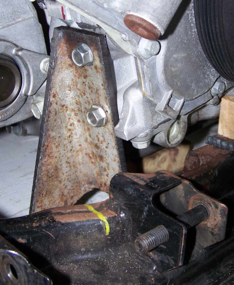
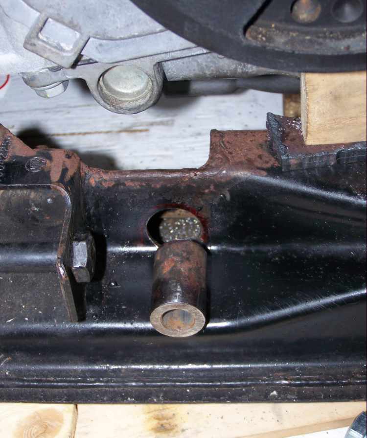
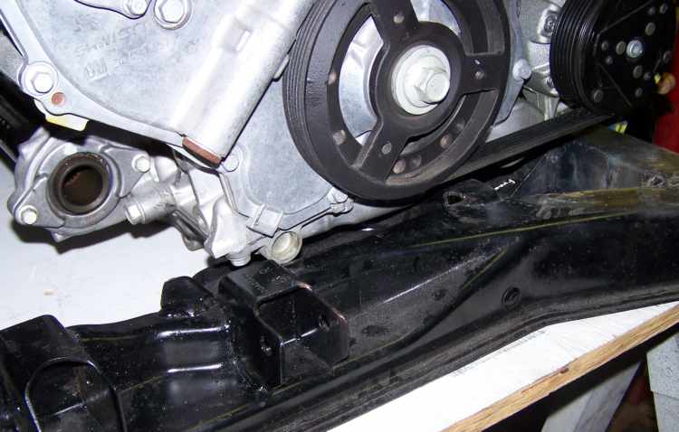
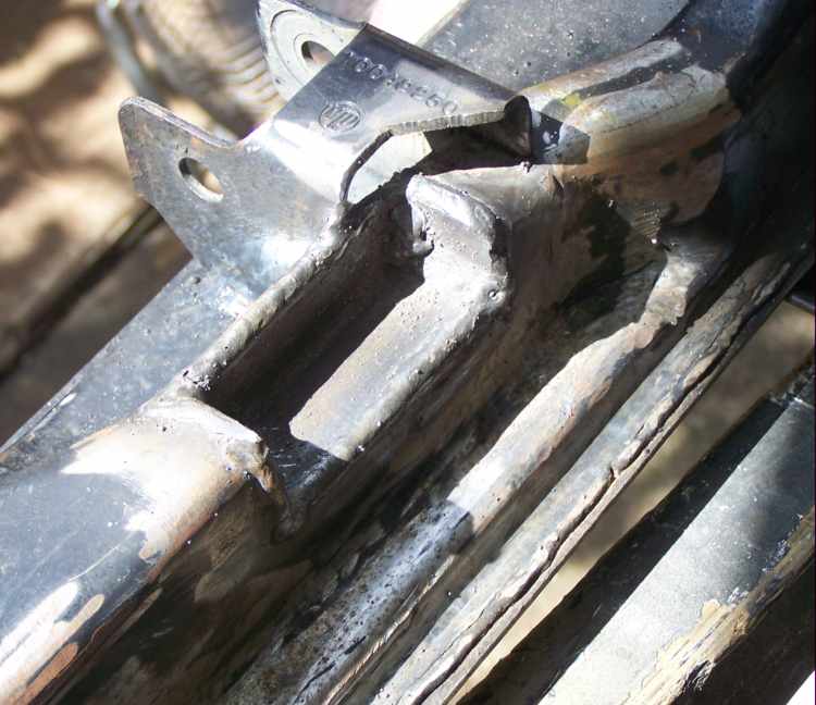
After centering the engine/transmission and setting the driveline hieght the oil pan is too close to the subframe rail.
That pluged port just about touches the frame. So I'm going to cut out a section and weld back in a piece to give it clearance.
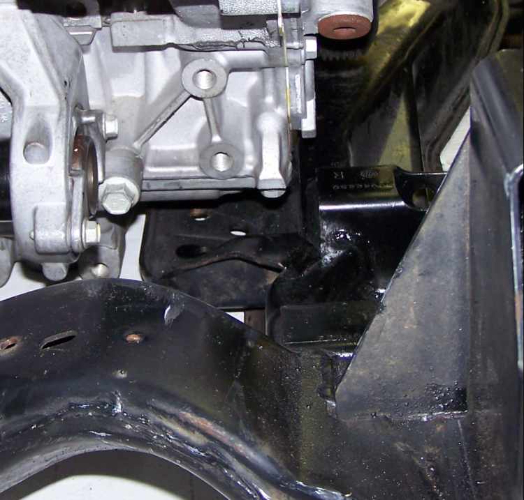
Looking down along the original 88 center mount, there is about an 1" of clearance between it and the bottom of the pan. I was hoping I could re-use it but there was any room for things like nuts, bolts and bushings.
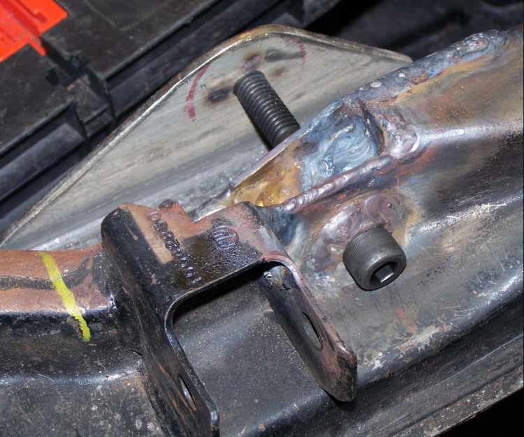
I welded a stiffener to the bottom of the subframe to keep everything in place before the amputation.
The section was removed and a piece of 1" angle was welded back in. I capped of both ends. I left the outside wall of the subframe to weld to.
I used the plasma cutter as close as I could the side pieces.
The drivers side. Not really a whole lot of metal holding things together.
The air chisel really worked well peeling the stub sheet metal off. Also did well on removing the bulk of the welds from the good metal. I was later told from a friend two blocks away he could hear the racket inside his garage.
------------------ yellow 88 GT, not stock white 88 notchie, 4 banger
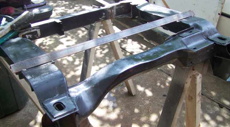
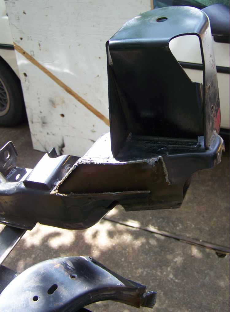
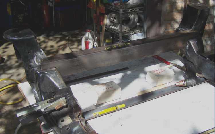
The factory rear transmission mount was too far away from the hard mnts on the F35 transmission. Rather then doing a funky dogleg transmission mnt it made sense to replace the rear crossmember with 2x3 tube and make a strait transmission mnt. Also raise the tube up to allow me to route the exhaust anywere under it. As a by product it makes it stiffer too.
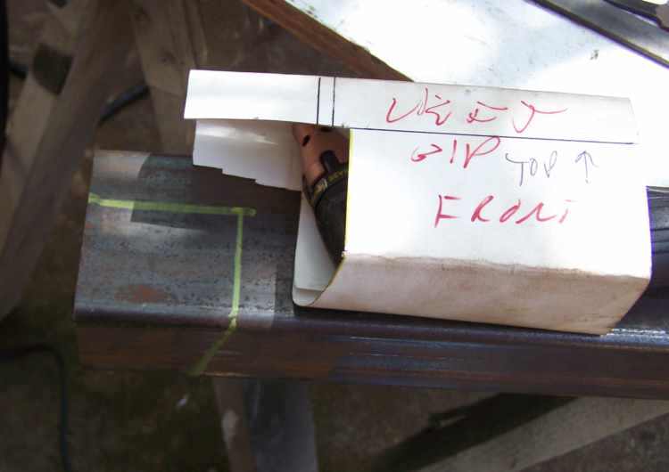
To get all the compound cuts and notches I used the old trick of wraping the tube in poster board, taped it up and used scissors to cut the paper templete. Then you just slide it back on the tube and mark it.
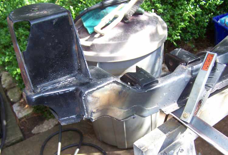
The top of the new cross member sits 1" over the subframe.
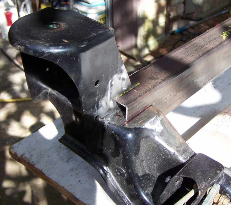
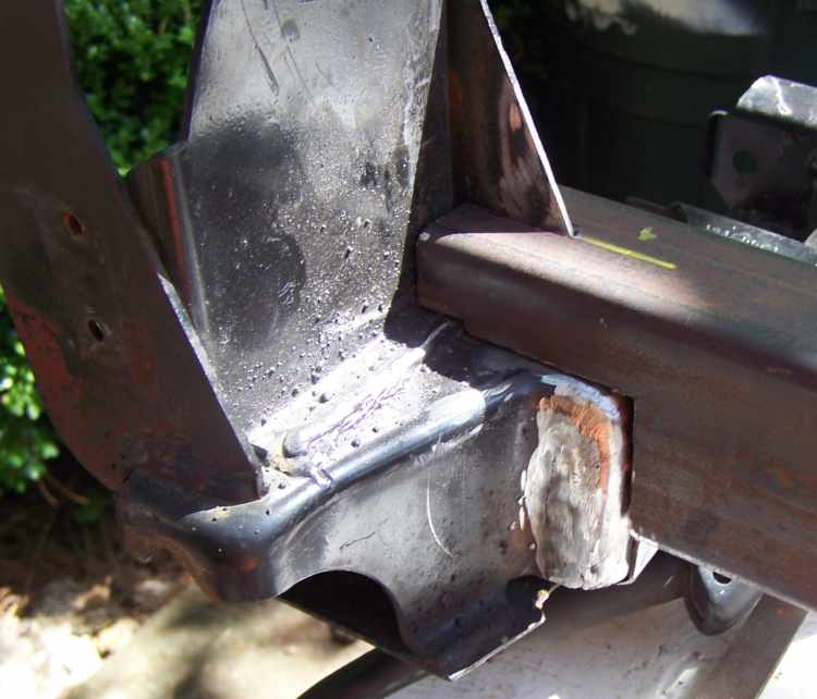
The tube is slotted and fits over the web of the rear chassis mnt tower. This will stiffen it up a little bit.
Here you can see how it's been trimed to fit the back side. Later it will be all MIG welded up.
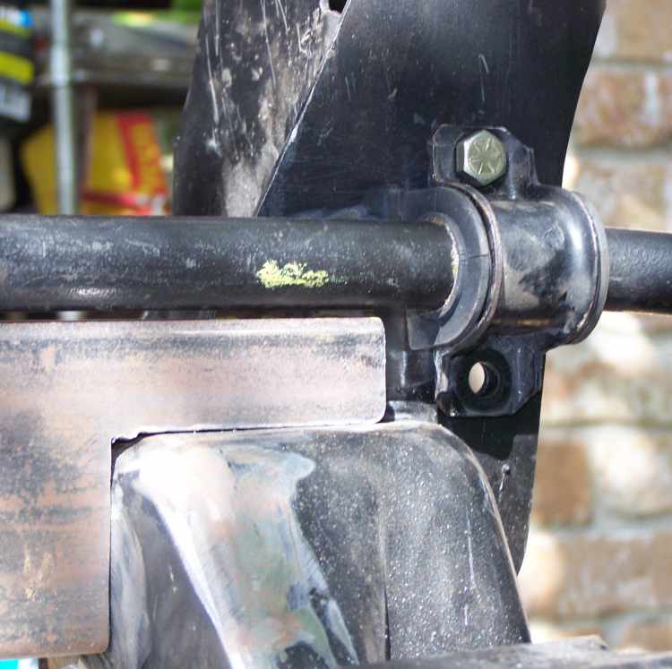
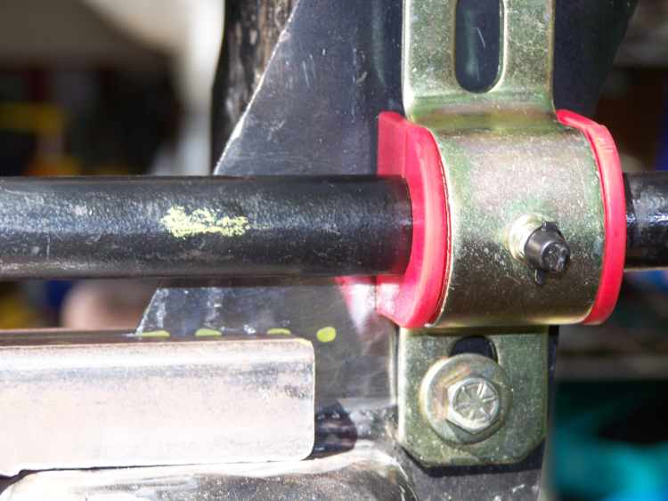
The factory rear bar and bushing has about a little over 1/8" clearance over the new piece.
Using a polypushing you can see it moves the bar up more. Addco bars use a simular bushing that you have to drill a new top hole.
I've made the front and rear transmission mounts and tacked them on the subframe. I worked on the center mnt today and I'm about halfway done with it. I should finish fabing it tomorrow and will post the transmission brackets pictures then.
Thanks for all the good words.
------------------ yellow 88 GT, not stock white 88 notchie, 4 banger
There could be a very cool little black box if somebodies good with PWM circuits.
Here's the goods to make the generator do its thing all the way.
The L-termanal control signal is a 5 Volt pulse with modulated (PWM) signal of 128Hz with a duty cycle of 0-100%. Normal duty cycle is 5-95%. The either extremes are for diagnostics purposes.
The following table shows command duty cycle and output voltage of generator. 0%______0V 10%_____11V 20%_____11.56V 30%_____12.12V 40%_____12.68V 50%_____13.25V 60%_____13.81V 70%_____14.37V 80%_____14.94V 90%_____15.5V 100%____13.8V
As you can see you could make a Dail-O-Voltage box with this data, if your real good with some programing you can combine timers with inputs so you boost idle voltage when the a/c comes on or just after it cranks for 20 seconds like the factory does.
Some stand alone efi controllors have programable PWM outputs just for stuff like this.
Any idea if the input to the alt. needs to supply any sort of current, or only a few mA? The last PWM box I made with a microcontroller was in the kHZ range, 128hZ should be easy to hit with plenty of processor power left over for checking inputs. If I ever get caught up with all the projects I'm working on I'll have to try this. I printed out the post as a reminder. If anyone's built one already, feel free to let me know so I won't be duplicating work.
Thanks for posting the pics. Really cool to see the progress. :-)
Would it be easier to use a non '88 cradle/Fiero, or would there be similar challenges involved in getting the engine mounted? Would similar problems exist with the alternator when using the stock ECM? (Would have to anyways to make the car C.A.R.B. certified)
Hey... In an effort to not hijack your thread into an alternator thread, I started a new one --> https://www.fiero.nl/forum/Forum2/HTML/085824.html about building an alternator "exciter" thingamabob. It's already prototyped and outputting 128Hz at a 50% duty cycle, just need to figure out how many inputs people would want on the thing and what voltage they should output... Also timers, etc... Should be cake.
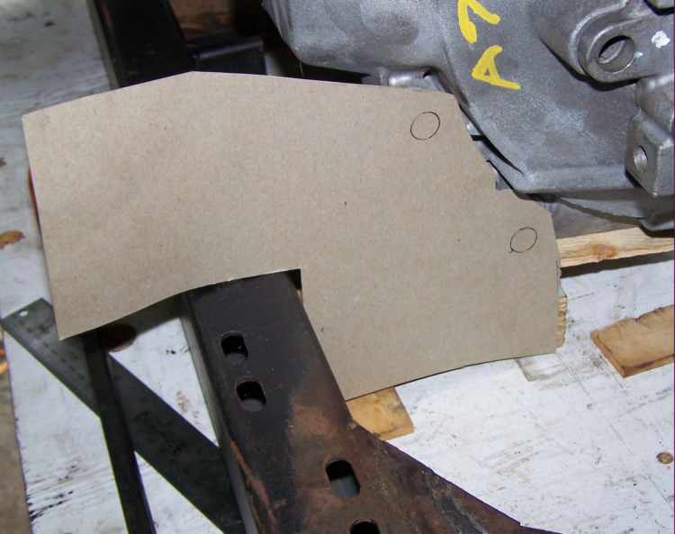
The brackets to mount the transmission are made from 1/4 plate steel cut by hand with the plasma cutter.
But first I made poster board templates after the engine is postioned relative to the subframe.
Fresh off the grinder.
The rear was done the same way, ovoiding the stock rear sway bar at full droop.
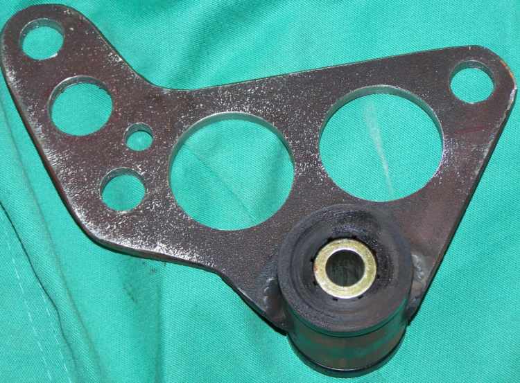
The 1/4 thick plate is great at the welds and bolt holes strength wise, but really too much metal for the job in the web areas, so a few well placed holes take a bite out of the excess weight while keeping it strong enough for the job.
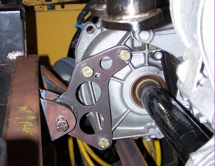
Same for the front mount.
Mounted in place it looks pretty cool too.
The 2x3 tube brackets are the same front and back from 1/8 flat bar stock. The 1/2 bolt hole was drilled through all 4 pieces at once on the drill press before they were welded on.
------------------ yellow 88 GT, not stock white 88 notchie, 4 banger
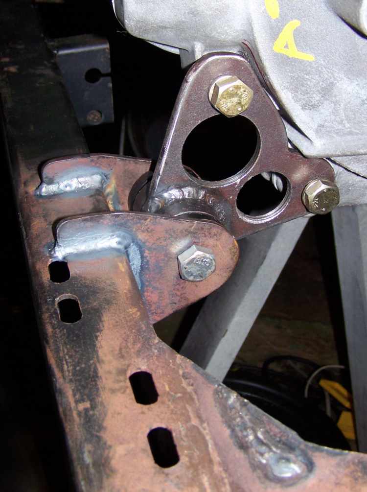
The center engine mount proved to be tricker then the other mounts. The engine has two good bolt bosses on the exhaust side. The best place for the mount would have been directly under the crank but there no good bolt bosses on the intake side to make a good straddle mount.
I had a big piece of 4" angle, 1/4 thick, that started the whole thing off.
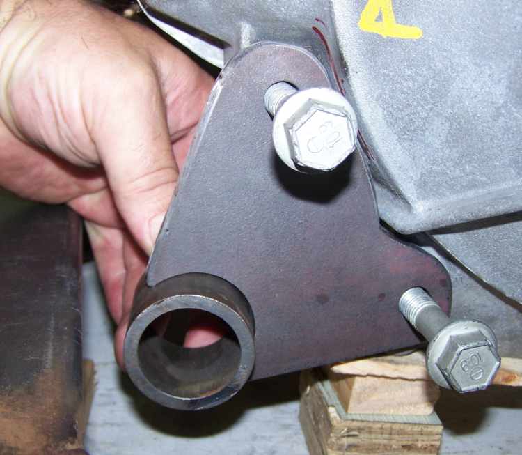
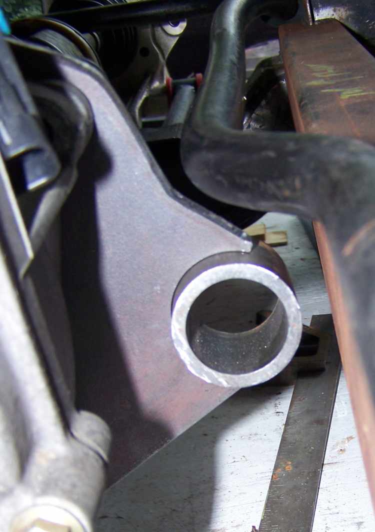
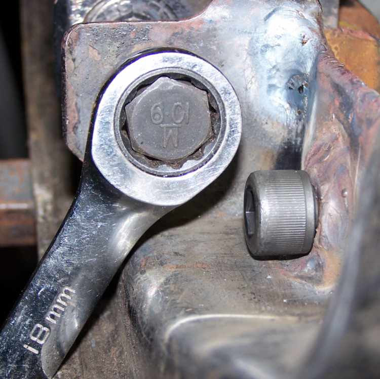
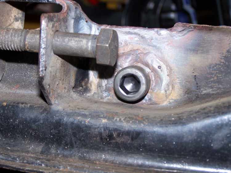
I placed the pivot in front of the toe link so I could get at both fasteners with a wrench. The crush tube goes through to the pocket.
Here it is welded up. The area directly under the bolt is releaved to allow clearance for the bushing once assembled.
Pleanty of room to put a wrench on it.
Fore & aft clearance.
The inside support bracket was cut from a c-channel piece from an old rack we had at work, it's 7/32 thick and over lapes the bottom of the subframe about an inch.
The center mount was made with really thick stuff so out came the drills.
Everything bolt up well enough to start the last mount, torque strap. I'll need to test fit the engine/subframe in the car then fab the strap.
------------------ yellow 88 GT, not stock white 88 notchie, 4 banger
I'm going to have to put it in if I'm ever going to drive the notchie again. Blew the 2.5L today at Texas World Speedway. Down shifted, blipped the throttle and my foot slipped off the brake pedal and matted the throttle just as I released the clutch. Don't know how high it went but lost a cylinder at turn one by then end of turn two I had zero oil pressure. Turned off the track before turn 3 and it sounded just like a VW flat 4 running on three.
So I'll be motivated to move this along as fast as I can or I'll miss some track time.
------------------ yellow 88 GT, not stock white 88 notchie, 4 banger


 If anyone's built one already, feel free to let me know so I won't be duplicating work.