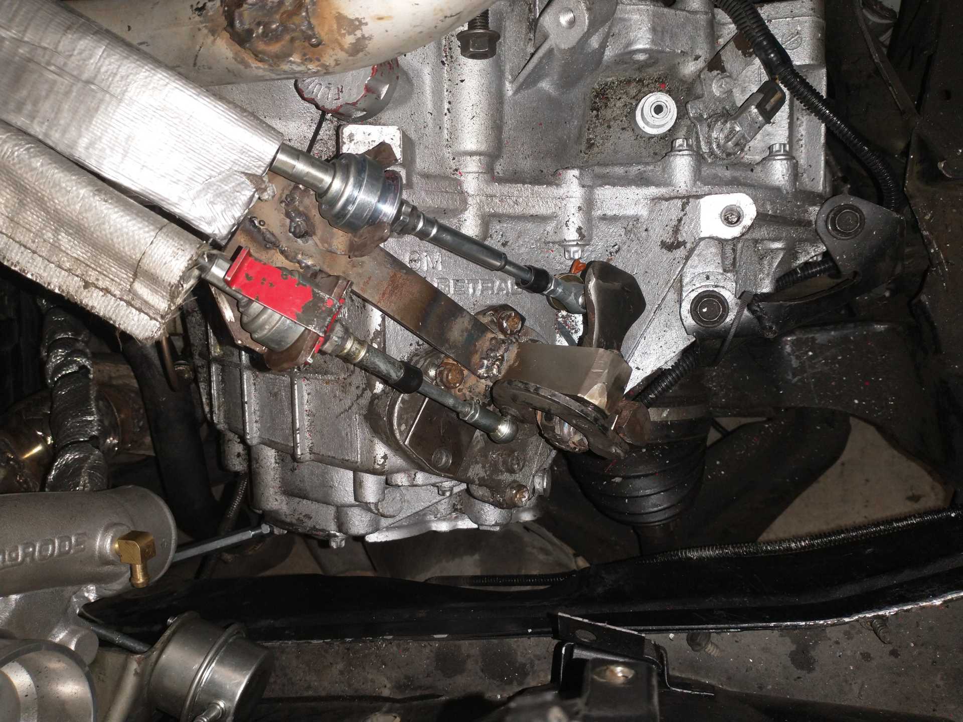
Well I got work done on my shifter today, it is 90% done. I am using the general idea of the f23 shifter, rotated 90* left, with the new select arm support "carved" out of some stainless steel, the arm is the f23 arm, and for the present the bushing (between the select arm and the shift arm) is also stainless steel (from my brief research, stainless and iron shouldn't have any issues being a bearing surface together, and I got it to have much less play than the old plastic one, much less than my 4 speed had to) The shift arm, I cut off the part where the cable used to attach, and ground down the opposite side weight to a flat section I will be attaching the shift cable to (just have to drill the hole). I'm using the Rodney select cable from my 4 speed, and I decided the shift cable was just a little too short, no matter what I did, so I got the 5 speed shift cable from Rodney (2ish inches longer), and it's perfect. It has the cables at a pretty good angle, at least visually, I shouldn't have much if any select effect from moving the shift cable, visually the shift cable is about 90*, select isn't as good, the support is maybe a hair to tall, tilting the arm towards the cabin, making the 1/2 to 3/4 movement slightly longer, lower effort, and 3/4 to 5/R a slightly shorter distance and higher effort on the shifter in the cabin.
Originally posted by 1985 Fiero GT: It has the cables at a pretty good angle, at least visually, I shouldn't have much if any select effect from moving the shift cable
Yes, the angles look reasonably good like that. I think that the stock F23 centering springs will work for you. Do the cables pass below the throttle body?
Yes, the angles look reasonably good like that. I think that the stock F23 centering springs will work for you. Do the cables pass below the throttle body?
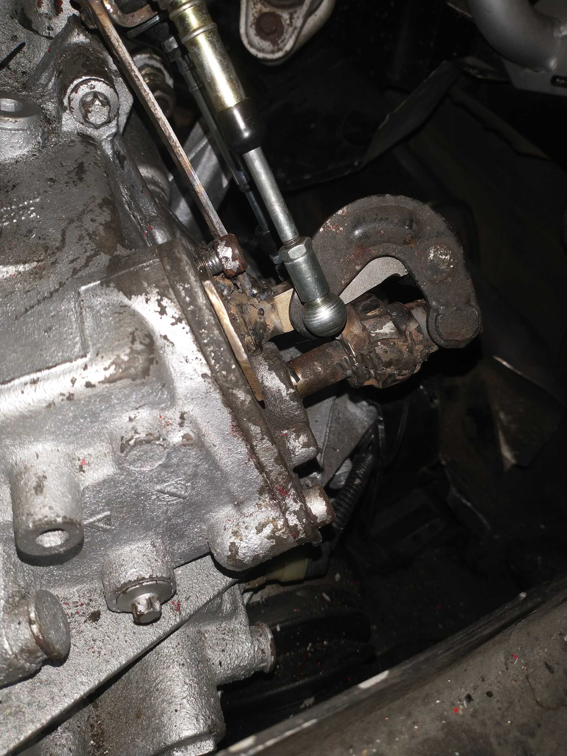
Your welds have a lack of fusion, it is like globs of metal sitting on top the the parts. This is not strong.
What kind of welding process are you doing?
Removing mill scale and rust before welding (to weld on clean shiny metal) is a simple thing you can do to improve weld quality.
Different kinds of sanding, flap discs, wire wheels, etc, all of that is good to clean up dirty steel before welding.
Yes, they run right over the y pipe, a little tighter than with the 4 speed, but the same direction and angle.
Yes with those welds, it was very hard, the upright piece is stainless steel, the base piece is steel, the cable mounts are iron I think, and I'm using a cheap fcaw welder, with stainless steel flux core wire. It goes on very globby or not at all, on the stainless exhaust it works pretty well, it still goes on globby, but grinding it down, there are no "seams" between the globs and the base material, but welding on those different materials is really tricky, maybe the welders bad, maybe the wire, maybe I'm bad, maybe all of the above haha!
Originally posted by 1985 Fiero GT: Yes with those welds, it was very hard, the upright piece is stainless steel, the base piece is steel, the cable mounts are iron I think, and I'm using a cheap fcaw welder, with stainless steel flux core wire. It goes on very globby or not at all, on the stainless exhaust it works pretty well, it still goes on globby, but grinding it down, there are no "seams" between the globs and the base material, but welding on those different materials is really tricky, maybe the welders bad, maybe the wire, maybe I'm bad, maybe all of the above haha!
I am running gas on my MIG, but the steel wire welds flatter than the stainless wire; it might be worth trying a different wire type.
Also check if your welder is wired with the correct polarity (if it can be switched) for what you're doing.
Part cleanliness is definitely a factor.
[This message has been edited by pmbrunelle (edited 04-10-2025).]
I am running gas on my MIG, but the steel wire welds flatter than the stainless wire; it might be worth trying a different wire type.
Also check if your welder is wired with the correct polarity (if if can be switched) for what you're doing.
Part cleanliness is definitely a factor.
Yeah, the stainless wire is pretty bad haha, and yes, the parts could definitely have been cleaned more, after the first couple fails on that shifter I started whacking it with a hammer to test the strength, once I had something that worked, I layered on more weld, the end result seems pretty strong, at least to my hammer haha
Well, today marked 2 years since my Fiero officially became my first car! Yesterday it got trailered back to my house (from winter storage, still missing the intake, that's the only real thing preventing it from being driven), so now I can clean up a bunch more stuff, get my exhaust leak free, and wrap it, and I'll probably redo that weld on the shift mechanism, I want to lower it a tad to get the cable alignment better, and that gives me a good excuse haha.
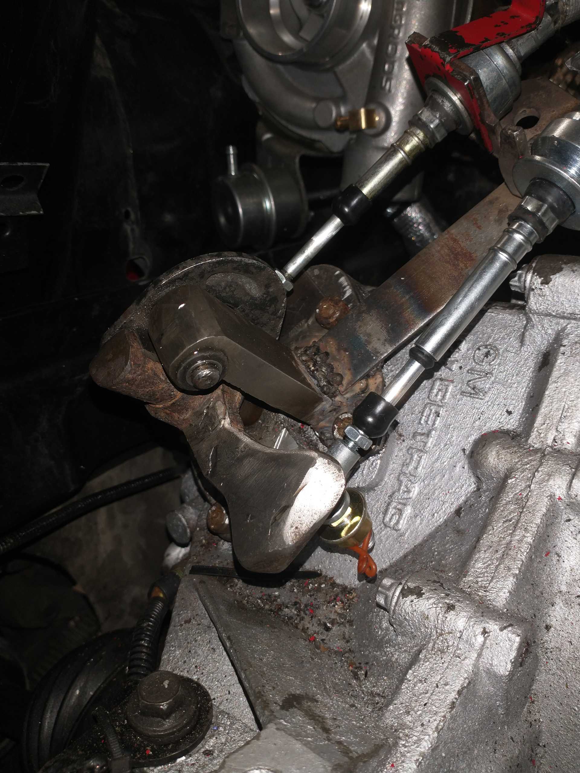
This evening I worked on the shifter mechanism, it is basically finished, I played with the cable lengths, which helped the unevenness I had when comparing the left movement to the right movement. The biggest thing I had still, was that moving from center to left was a little too loose, center to right was a little too stiff, so I used the right centering spring from the 4 speed shifter mechanism (technically a spare I had) and that made it to strong to the right, so I played with that spring, heating and bending the end a few mm to reduce the tension, and in the end it is pretty good, even pressure to move the shifter left or right, shift knob is well centered (center neutral is just a tad left and back from perfectly upright). Shift cable appears to be 90*from arm, select cable lines up well, and the lengths are just right. Tomorrow I'll finish the exhaust, and add a second support for the shift cables from elsewhere on the transmission, make sure the cable mounts are welded well, and clean up/paint the mechanism.
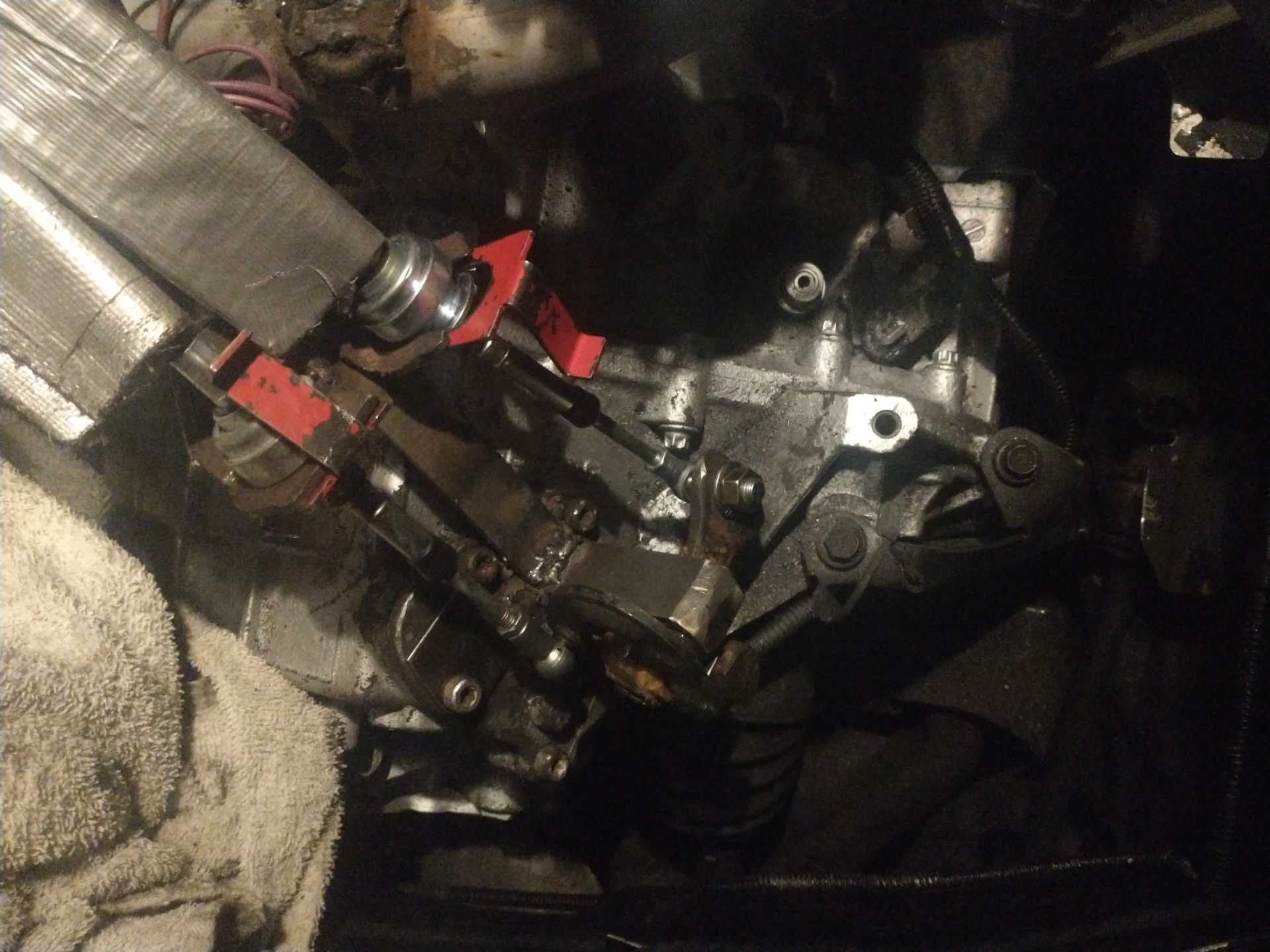
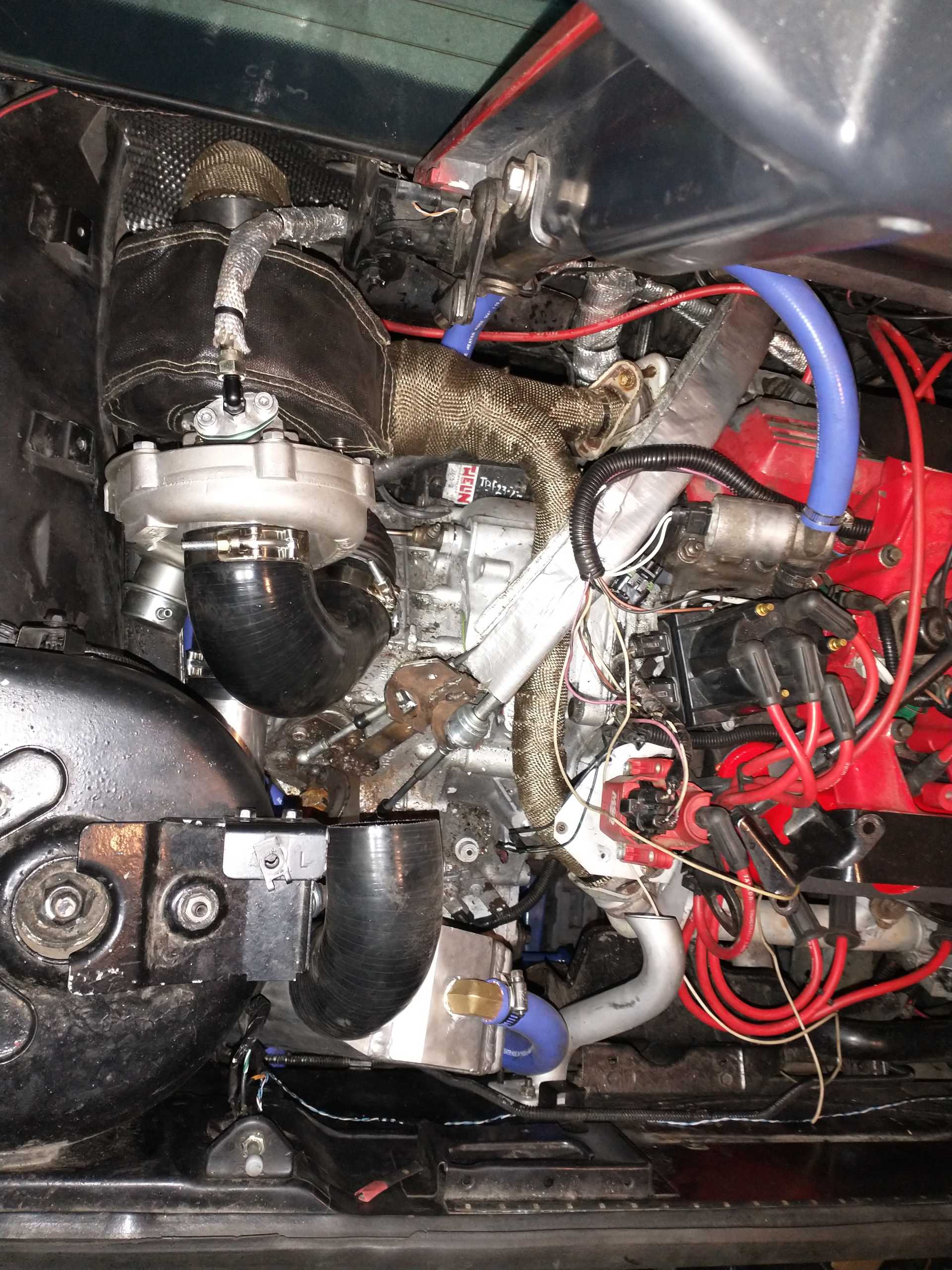
Didn't get as much done yesterday as I'd hoped, but it was good progress nonetheless. For heat management, I wrapped the fuel fill pipes with reflective fiberglass insulation (like what's on the shifter cables but in a roll to wrap around), because they'll be closer to the exhaust now, then installed some aluminum heat shield material on the firewall over that area, from the frame rail to an inch or so past the decklid hinge, from the top (bottom of window) to about 1.5 feet down, then I wrapped the y pipe and downpipe, and I'll have a "turbo blanket" on. With all that it shouldn't be much more heat in the engine bay than stock, and I definitely shouldn't be heating up those fuel fill pipes with 3 different layers and types of insulation between them and the exhaust. A lot of the turbo heat will be able to go straight out of the decklid vent, as it's right under it.
Oh, almost forgot, I also ported the internal wastegate, by opening up the hole, curving the sharp edge to draw exhaust into it better, and grinding under the wastegate flapper to let it open further, in a similar manner to "the white bug"
[This message has been edited by 1985 Fiero GT (edited 04-19-2025).]
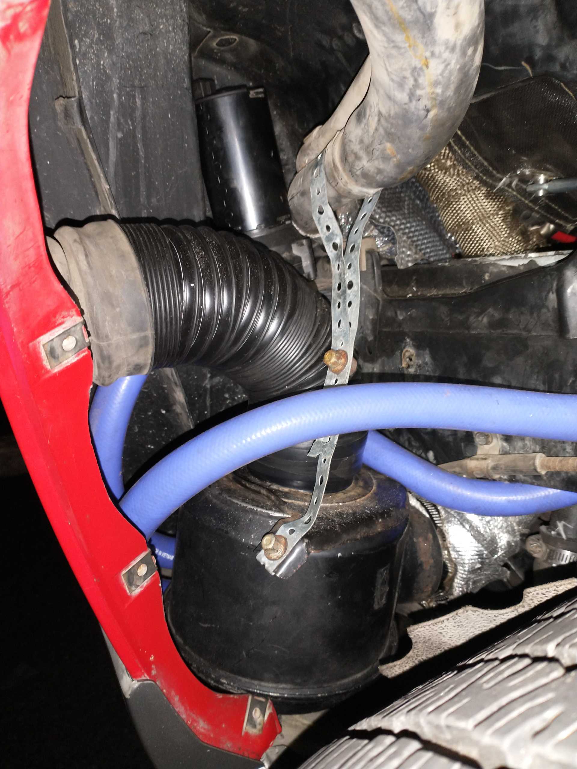
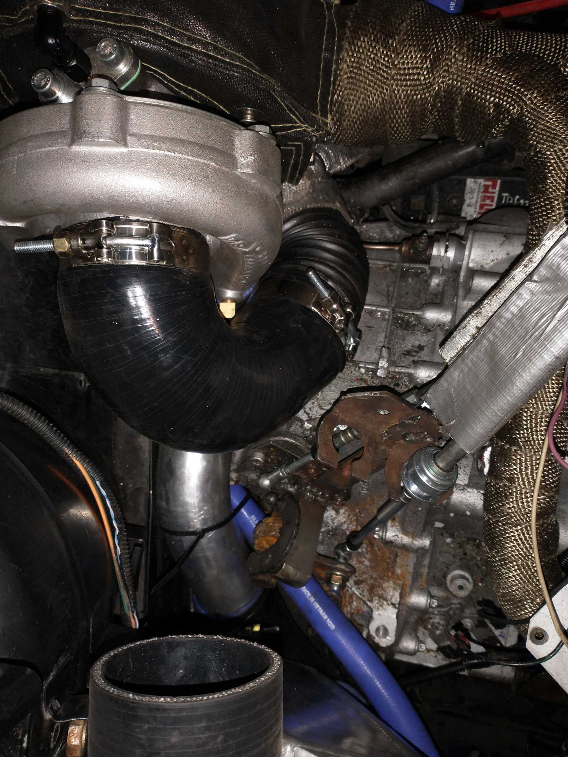
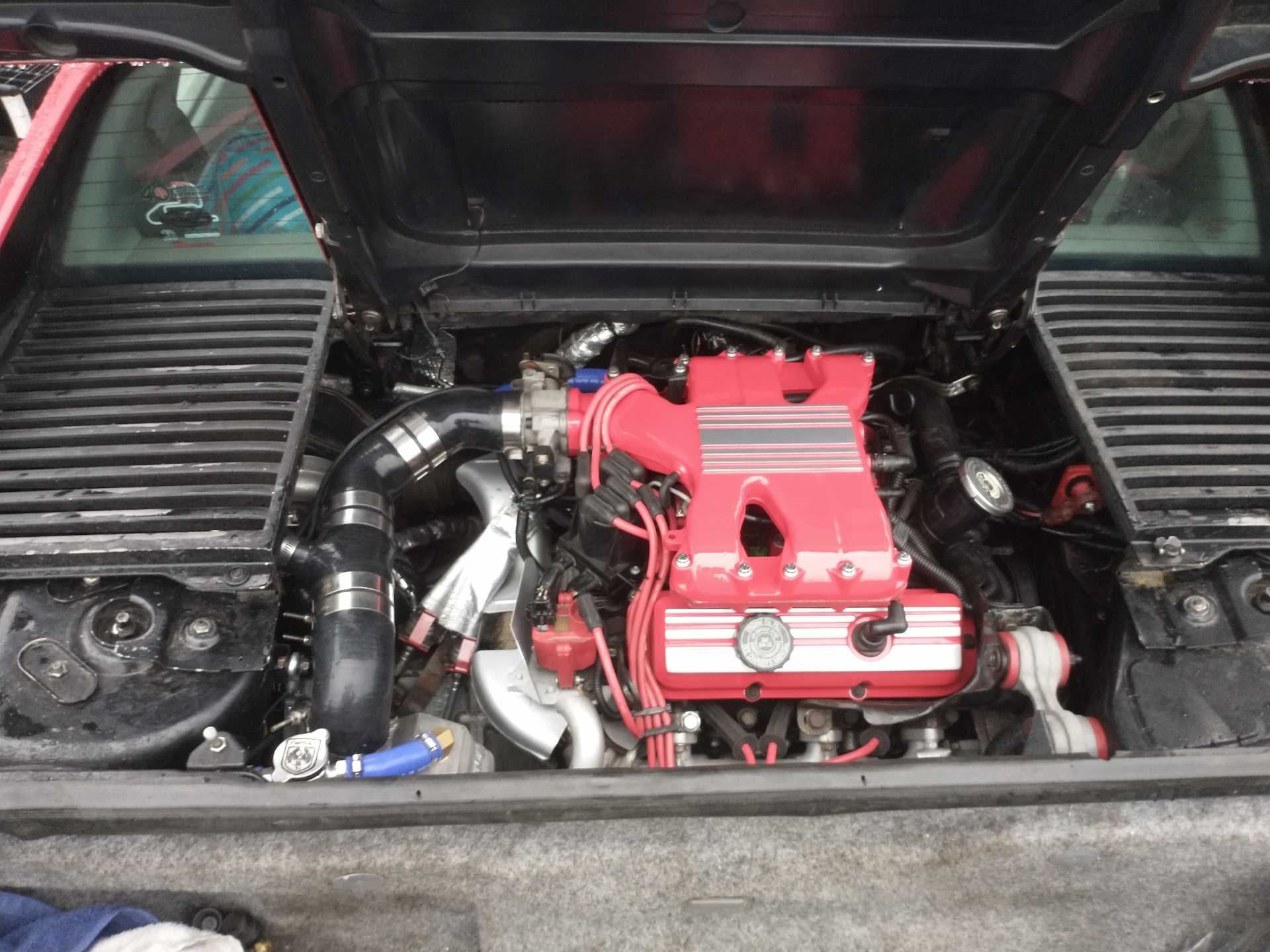
Well I worked on the intake late last night, got it done all the way from the cold air intake to the recirculating blow-off valve after the intercooler. In the fender, I have the stock air filter housing upside down, with the output going under the lower frame rail by the coolant pipe, about 2" from the wrapped exhaust, and it's wrapped in the reflective fiberglass insulation tape. From there it comes up by the shift linkage and around into the turbo. Then from the turbo, it's a 90* 2"-2.5", then a 45* downwards pointing aluminum pipe, then a 135* up into the intercooler. From there, it's a 90* towards the cabin, then the piece for the 1" recirculating blow-off valve, which outputs straight into the large 135* turbo inlet pipe
The intercooler placement is such that the silicone will be running along the decklid reinforcement bump, very very close (like half a cm), and there's at least an inch and a half between the lower intake piping and the axle boot. The blow-off valve doesn't interfere with the decklid vent.
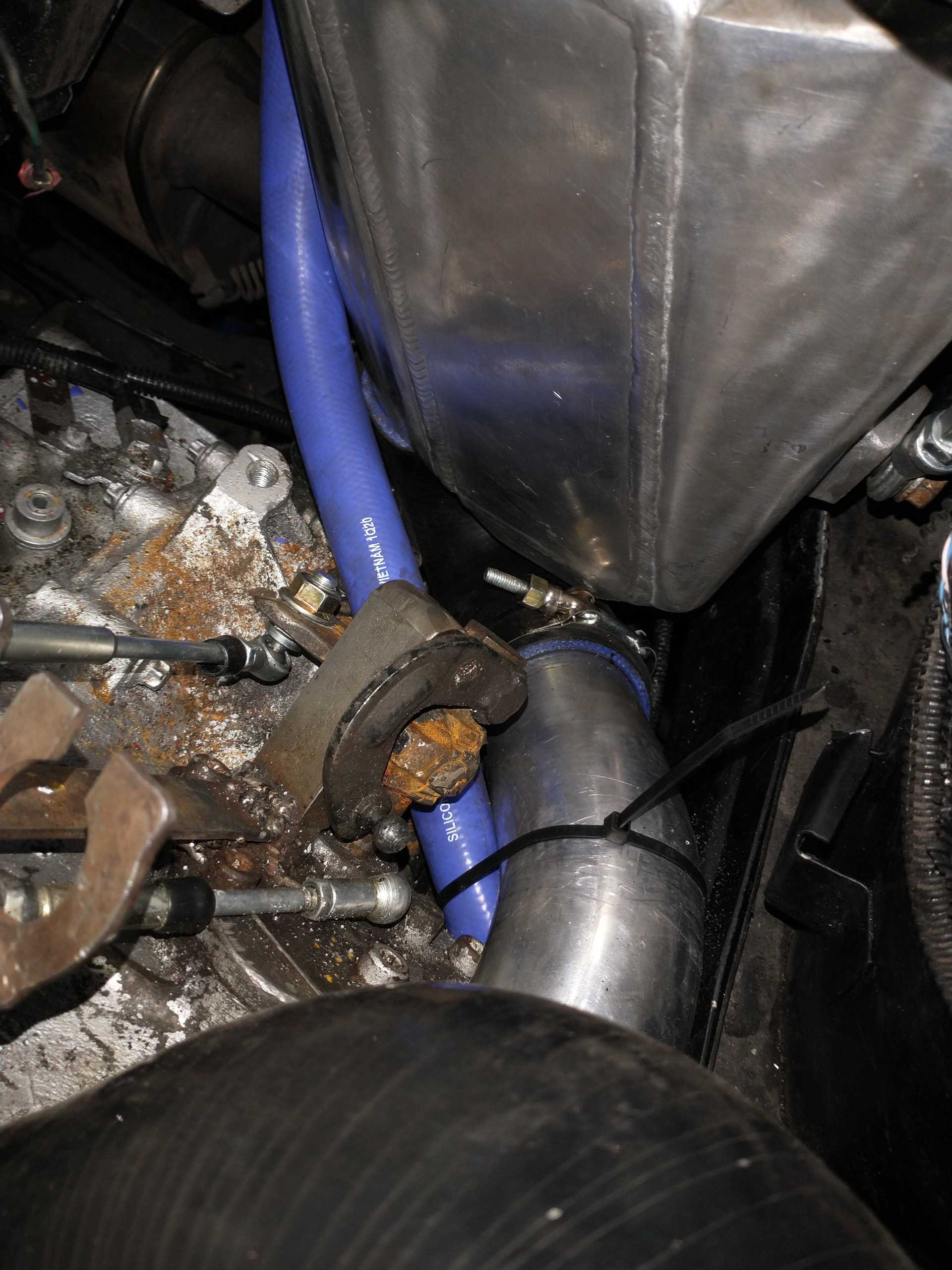
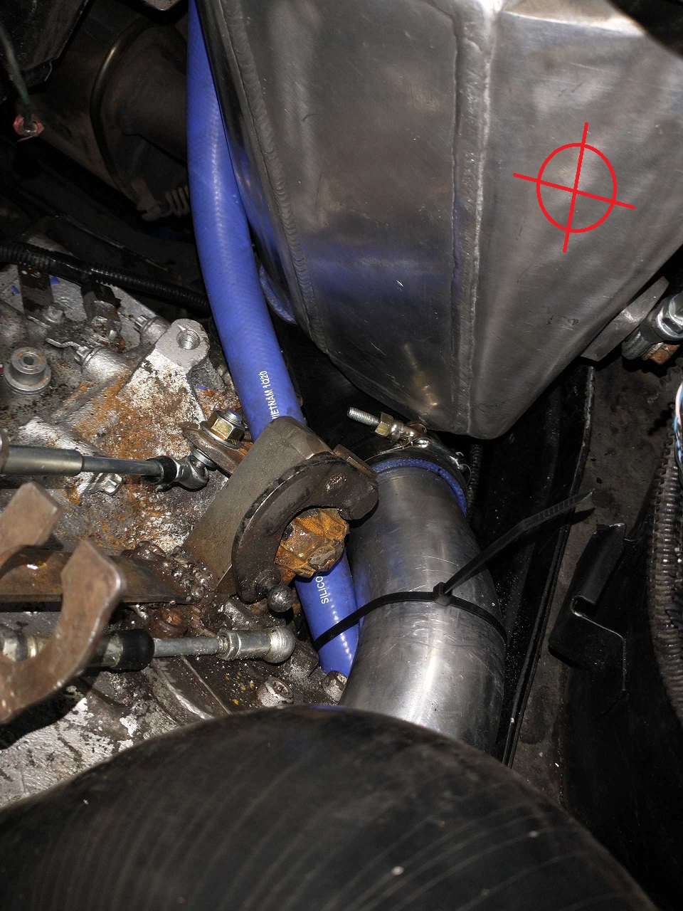
The intercooler core is supported from a tab on the shock tower using a stainless go kart tie rod, basically an adjustable threaded rod with ball ends, credit goes to pm Brunelle, who uses something like this to support the turbo (although he used actual hardware, not a go kart tie rod haha)
The intercooler water lines are both run down the fuel tank on the side opposite the heater pipes, using the clamps for the AC pipes I don't have, they are plenty high up and stiff, they won't touch the ground even if the car does. Intercooler pump is in the fender with the air filter, with the hot line (outlet) running to the top of the Intercooler along the bottom of the lower intake pipes, and the cold line (inlet) running to the bottom, going through holes in the lower frame rail to go over the axle/tie rod without interference. I haven't touched the intercooler radiator yet as my cars nose is in the ground for the rear to be high enough to easily work on, soon though.
The last picture shows where the boost controller is, it's a EGR solenoid from something or another, fastened to a tab on the front of the strut tower, already hooked up, although initially I'll leave the wastegate disconnected from the flapper, so I can make sure I ported the wastegate passage enough and don't have boost creep.
I also wired the crank VR sensor to the distributor ICM, and the ICM tach output to the megasquirt.
As of right now it is basically ready to fire, tune and go on the turbo side of things, what's stopping me is that my intake is in the mail back to me, and my starter is having issues, so a replacement is also in the mail, although that's not the most critical, I'm parked on a hill haha. I still have to install the evap canister, and PCV venting system (which will be a cheapo little catchcan with 3 ports, one to the PCV valve directly, one to manifold vacuum with a one way valve (it'll suck PCV gases when under vacuum but not boost), and the other to the air filter housing (with a one way valve so the manifold vacuum can't suck from it, but under boost any extra pressure in the PCV or slight vacuum in the filter box pre turbo will allow it to suck the PCV that way) the front valve cover vent will just be a filtered intake. I did this to have a single catchcan to cover both in vacuum and in boost crankcase ventilation. Catchcan and evap canister will be located on top of the battery (super small battery on its side in stock location, plenty of space)
Hey, quick question on this. Does the orientation of the shifter bracket... meaning how far or close from the armature, make any difference on the shifting of the transmission? I noticed you fabricated your own linkage for the original cables, and just curious how you determined how far out they should be mounted. Was it more or less just where it felt "ok" ... was there some measurement or anything you went through?
I ask because my daughter's transmission feels a bit notchy getting into first, or reverse... otherwise shifts from 1st to 2nd, and 2nd to 3rd are very smooth.
Originally posted by 82-T/A [At Work]: Hey, quick question on this. Does the orientation of the shifter bracket... meaning how far or close from the armature, make any difference on the shifting of the transmission? I noticed you fabricated your own linkage for the original cables, and just curious how you determined how far out they should be mounted. Was it more or less just where it felt "ok" ... was there some measurement or anything you went through?
I ask because my daughter's transmission feels a bit notchy getting into first, or reverse... otherwise shifts from 1st to 2nd, and 2nd to 3rd are very smooth.
Thanks!
For minor distance changes, it only changes the positioning of the shift lever, say it was half an inch off on the select cable, well the shifter would operate permanently biased a little left or right, any more than a little length difference, and the lever wouldn't have enough travel (1/2 on the shift knob would be 3/4 if it was too far out, or 5/r would be 3/4, or 1/n would be n/2, etc.) for mine I just found the half way point in the total value travel, and roughly aligned that with the center neutral position on the trans, I then made a slight adjustment on the select cable using the threaded ends, but not much. I don't think that would be why AJ's car is notchy into first and reverse, is that just with the engine off, engine on, moving, stopped, all the time, etc? It would logically make sense why 1st and reverse would be notchier, the synchros aren't necessarily lined up, and the wheels aren't going to turn, so when "forcing" it into gear (going through the notch), you're turning ask the other gears and clutch side of the trans until it lines up, lower gears will turn the engine side more, so you're moving more stuff to push through a synchro that isn't perfectly lined up in a lower gear, although theoretically that scenario would be fixed when moving out the engine running (clutch down)
Got the intercooler radiator mounted up front, and hooked into the hoses and filled with 50/50 antifreeze/distilled water, got the evap canister and catchcan hooked up yesterday, the factory heat shields back on, I'm basically done now, some zip ties here and there, a little bit of wiring still (intercooler fans, interior). I ended up hooking the ICM spark bypass signal wire to the TPS 5v, so it's always controlled by the ECM, no point wasting an output on something that'll always be on anyways.
Originally posted by 1985 Fiero GT: can't start it until I have the new starter, tried bump starting it, but not enough of a hill.
Normally with a fresh ECU install I think you would need a strong battery + starter with all the engine start attempts that would be performed for tuning purposes.
However, in this case, you have a good head start with information from my tune!
Normally with a fresh ECU install I think you would need a strong battery + starter with all the engine start attempts that would be performed for tuning purposes.
However, in this case, you have a good head start with information from my tune!
Yup, ironically that didn't save my starter (although I would call that a defect, for a failure after basically 10 normal cranks and the compression testing I did) but yes, starting off with something roughly in the area is beneficial indeed!
I did my tune for the 4.10 Muncie, which had fairly high highway revs.
I prepared a new tune that's a bit more optimised (more spark advance, less rich mixture) at the cruise RPM I expect with the F23. If you're curious about that I can share it with you.
I did my tune for the 4.10 Muncie, which had fairly high highway revs.
I prepared a new tune that's a bit more optimised (more spark advance, less rich mixture) at the cruise RPM I expect with the F23. If you're curious about that I can share it with you.
Ok, good to know, but I want to fiddle with this for myself for a while once I get it running, I might want to compare/replicate things sometime, but for now I'm good, I like to start with something known good/decent (aspects of your old tune to get it started the first time) then play with things and learn what does what as I go, making improvements, and seeing what works and doesn't work, I'm sure I'll want to compare, once I've actually had some experience doing it myself, but I'm excited to start this very soon now haha, thanks though.
I've also been reading the 86 pages of the White Bug build on the Montreal Fieros site, almost as a final checklist to make sure there isn't anything major I'm missing or might want to do, only thing I've specifically discovered is that I put my mat sensor in the wrong place probably, I'll likely have heat soak on hot startup with it, I installed the mat sensor threaded into a piece of a fitting, threaded into the EGR tube location nice and tight so I don't anticipate vacuum leaks, and I have a catchcan so hopefully it won't be pouring oil onto it, but being nestled in/on the engine like that will hear the sensor up a bit, although I will be measuring the temperature post turbo and post intercooler this way. Oh well, I saw a setting to ignore mat sensor for x amount of time after startup, along with the mat/coolant blending, I should be able to make it work if I have heat soak.
[This message has been edited by 1985 Fiero GT (edited 04-24-2025).]
I think that under the intake manifold the sensor will be highly influenced by the temperature of the manifold's metal in there... not so good.
I experienced heatsoak with the sensor when it was (previously) in the stock metal air filter can. This air filter can, being near the engine, but also being lightweight, could be easily heated from residual engine heat after shutdown.
For your car, I think a good place for the sensor would be to screw it directly into the outlet air tank of the intercooler. The intercooler has a large effect on the air temperature, so it is not so bad for the sensor's reading to be skewed by the temperature of the intercooler's metal. Also, seeing as the intercooler is a large mass of aluminium and water, I don't think that it will heatsoak much from residual engine heat after shutdown.
It is almost always easier to fix hardware problems with hardware than it is to try fixing hardware problems with software.
[This message has been edited by pmbrunelle (edited 04-25-2025).]
I think that under the intake manifold the sensor will be highly influenced by the temperature of the manifold's metal in there... not so good.
I experienced heatsoak with the sensor when it was (previously) in the stock metal air filter can. This air filter can, being near the engine, but also being lightweight, could be easily heated from residual engine heat after shutdown.
For your car, I think a good place for the sensor would be to screw it directly into the outlet air tank of the intercooler. The intercooler has a large effect on the air temperature, so it is not so bad for the sensor's reading to be skewed by the temperature of the intercooler's metal. Also, seeing as the intercooler is a large mass of aluminium and water, I don't think that it will heatsoak much from residual engine heat after shutdown.
It is almost always easier to fix hardware problems with hardware than it is to try fixing hardware problems with software.
Yeah, I figure it'll definitely be an issue, until I see how big of an issue, I'm leaving it as is though, it won't be incredibly easy to change, the intercooler has no temp sensor threads (has 2 M8 mounting screw locations that go into the tank, I'm using the cold side one for the support, and the hot side one is not useful to me, also the cold side is the one jammed between the strut tower and trunk, nowhere to add a sensor. An idea I guess is to add a water temp sensor (1/8npt) to the intercooler radiator up front, that should be basically the temperature of the air going into the engine, I mean it would be more accurate than in the intake haha, bit I have to find an accurate 1/8npt sender.
[This message has been edited by 1985 Fiero GT (edited 04-25-2025).]
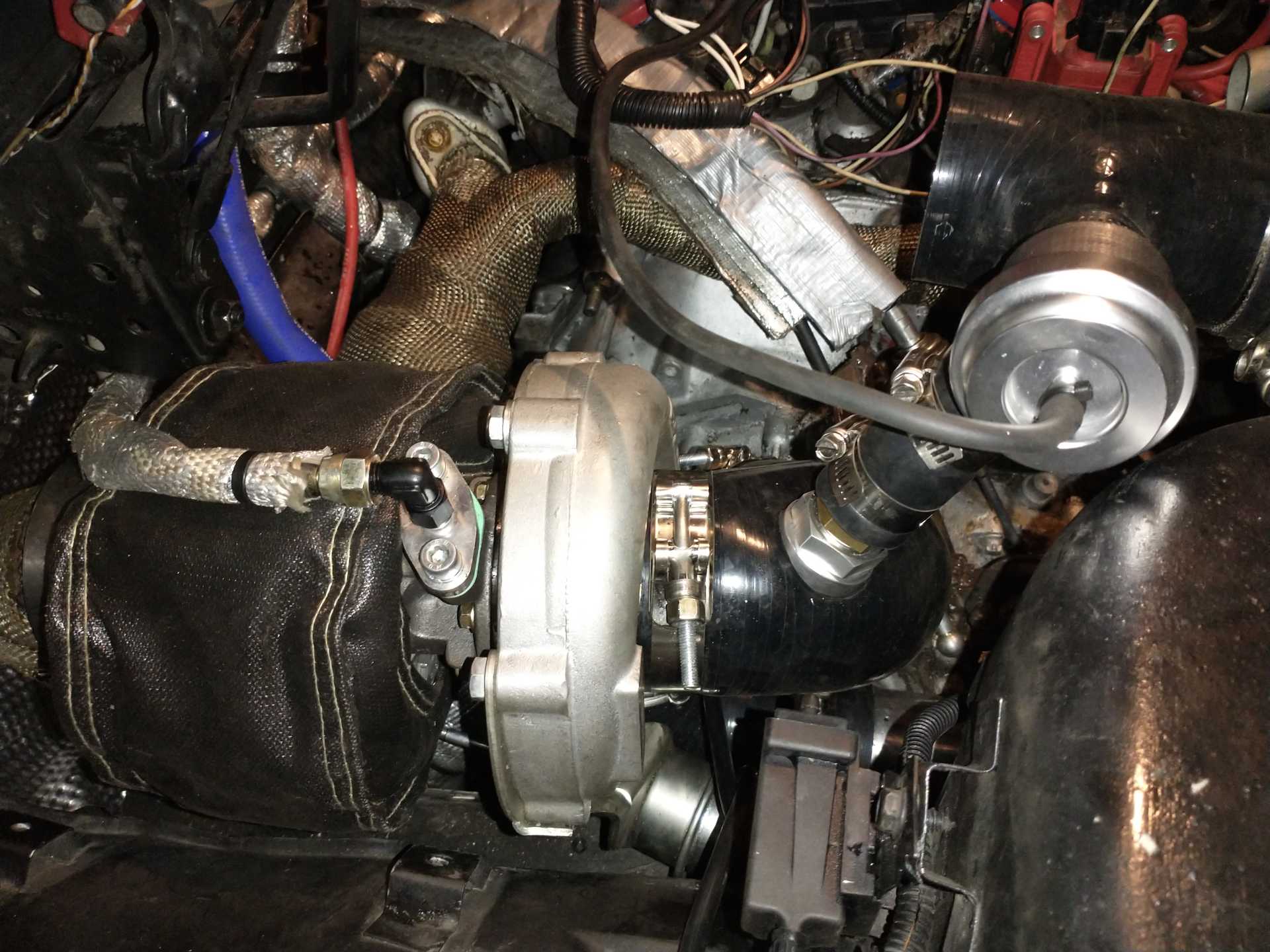
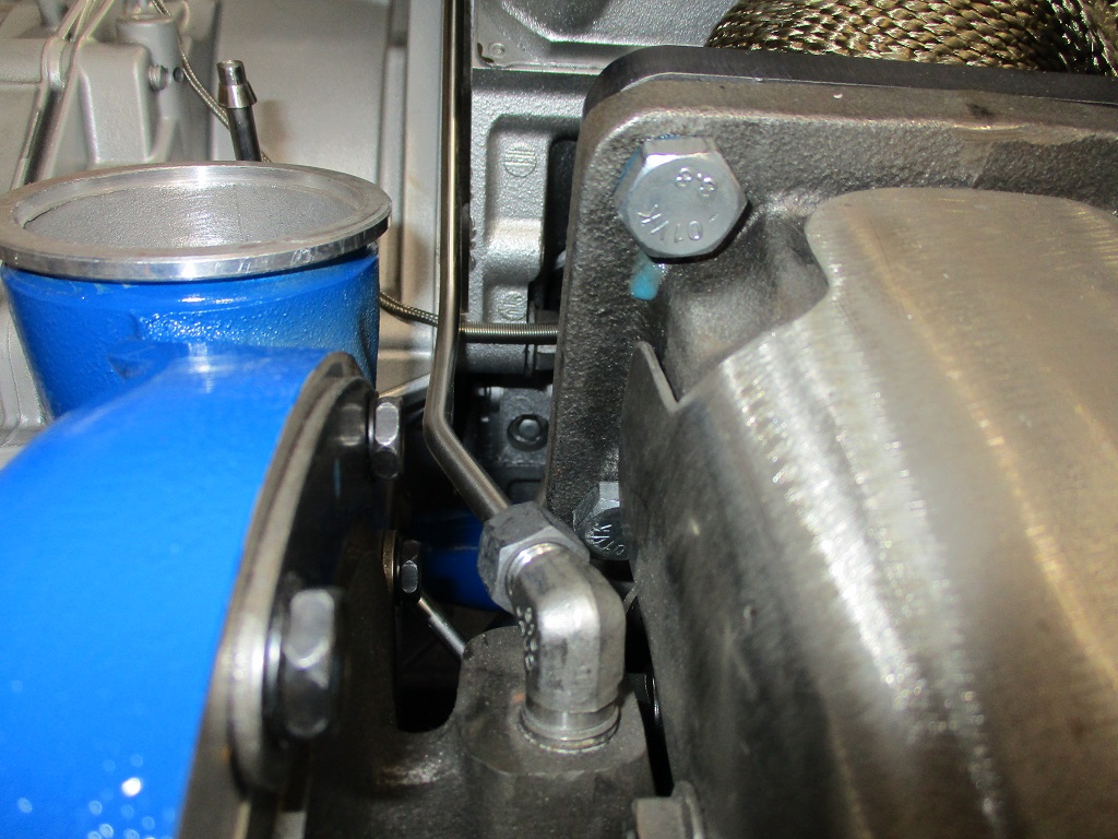
Well I got my starter today and did a little bit of testing, even got to do a tiny bit of driving, didn't get anywhere far though, and I got a surprise at the end, my oil pressure line leaked onto the back of the turbo, I caught it immediately (fire extinguisher always in car) and a hose nearby, so that was fun, it's not a Fiero if it hasn't caught fire, right? Oh well, no damage other than some insulation and the oil line, admittedly my routing put it right over the uninsulated v band, so totally my fault.
The driving I did was under 2500 rpm, low low throttle, just to run through the gears and do a little tuning, the sync loss was much better but still not perfect, I think it went to 3400 once, when I was exploring the pedal a bit, but I encountered sync loss once or twice, so I stayed low after that, I think I got 105 kpa, so technically I was under boost, that was less than a third throttle and 2500 or so, it felt good, fun to be back in my Fiero, however bad it was running haha, I will say the clutch has a very small friction point, I stalled more than once, but it isn't too bad, I'll get used to it. The crank sensor is hooked up to the distributor, and next I'll check if pulling the sensor slightly out helps, in testing the last time it did slightly help, but it was worse to start with and better now, so I'll see about that.
Edit, I've ordered new hoses, real Teflon ones from silicone intakes, both the feed and return (no issue with the current return yet, but it isn't Teflon, so I'll have the replacement ready), pmbrunnelle, what do you use to heat shield your feed and return, the "reflective intake wrap" I was using didn't hold up very well anywhere near the turbo (I don't know if that was the heat or the fire haha). Other than some of that insulation, and some melted zip ties and split loom, and the oil line that looks like the plastic (rubber?) melted on the inside and squeezed out through the metal shell (leaking oil there, right onto the v band), there doesn't seem to be any real damage, I'm glad I had my fire extinguisher and a hose on hand. Anyhow I need to order some different insulation, to wrap around the oil lines, the pre turbo intake (runs closer to the exhaust), and some wire harnesses maybe.
[This message has been edited by 1985 Fiero GT (edited 04-25-2025).]
You can run a stainless hard line for the oil feed and not worry about it melting or getting brittle.
I don't have anything to bend or flare or anything for hard lines, I trust a real hose will likely be fine, my burnt one was the garbage cheap one that came with the turbo, I suspected it would be delicate, but I messed up by forgetting that the v band gets hot to. I will change the routing and it'll be a real PTFE hose now (when I get it).
I don't have anything to bend or flare or anything for hard lines, I trust a real hose will likely be fine, my burnt one was the garbage cheap one that came with the turbo, I suspected it would be delicate, but I messed up by forgetting that the v band gets hot to. I will change the routing and it'll be a real PTFE hose now (when I get it).
If you use swagelock or other compression fittings, then there is no need to flare. You can also bend the lines over pipe or other round objects if you dont have a tubing bender.
If you use swagelock or other compression fittings, then there is no need to flare. You can also bend the lines over pipe or other round objects if you dont have a tubing bender.
Ok, I'll keep that in mind, and do some research, any suggestions for hose/tubing/wiring insulation?
I didn’t use a heat sleeve on the supply line seeing as it is cooled by oil flow in operation, but it might be prudent to do so.
I slid the sleeving onto the hose (along with Oetiker clamps) before installing the end fittings. Then, I secured the sleeving to the hose by tightening the Oetikers.
A hard line can be good too, but it needs to be planned with just the right amount of flex. Too stiff, and it can break with engine movement or temperature changes. Too flexible, and it can fatigue and break with engine vibration.
Oh, digikey, never thought to check there, every time I come across them they surprise me with how much stuff they have, thanks.
FWIW, when my oil feed line blew on my car years ago, it was a silicone intakes hose. my current hose is a braided stainless line, my next move will be tubing as Fieroguru suggested. That said, if you go tubing, make sure there are enough direction changes to allow for thermal expansion and contraction, the turbo can engine up moving quite a bit as things get hot.
------------------ "I am not what you so glibly call to be a civilized man. I have broken with society for reasons which I alone am able to appreciate. I am therefore not subject to it's stupid laws, and I ask you to never allude to them in my presence again."
I invited Lou Dias to trash me in my own thread, he refused. sorry. if he trashes your thread going after me. I tried.
FWIW, when my oil feed line blew on my car years ago, it was a silicone intakes hose. my current hose is a braided stainless line, my next move will be tubing as Fieroguru suggested. That said, if you go tubing, make sure there are enough direction changes to allow for thermal expansion and contraction, the turbo can engine up moving quite a bit as things get hot.
Yeah I ordered a silicone intakes stainless braided PTFE line, the rubber braided hose I had lasted for at least an hour, basically resting on the v band (I don't know how close it was, but it was way too close). I'll put some wrap around the v band, better insulate the line, and reroute it so it is farther away, that should give a reliable life, but I'll look into hard tubing, and I bought a new fire extinguisher just in case haha (I didn't fully use the old one so I'll keep that in the trunk or frunk, just because).
Ok, looking at a datalog, my coolant temp started out at 190, mat 125, throughout the 7 minute datalog, coolant went up to 205, mat went down to 113, outside temp was probably 60 or so. I'll probably put the sensor in the intercooler, but I'll probably braze a female bung onto it, I should be able to do that easier than finding a big tap (and I don't know how thick it is).
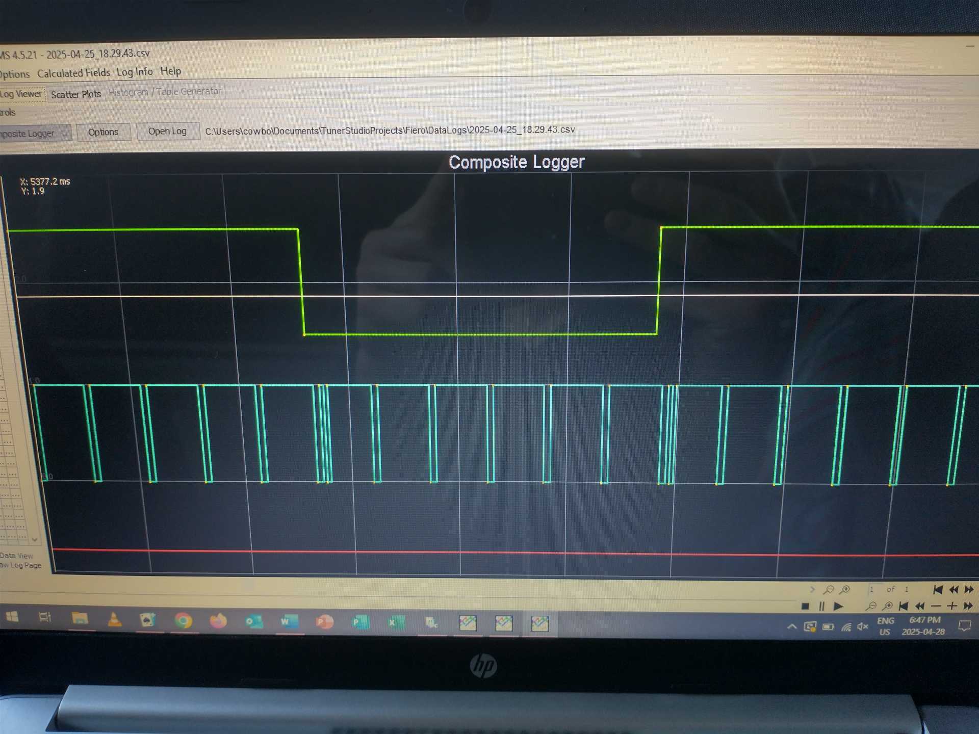
This is a picture of my crank signal composite log, the teeth are nice and even now that the distributor is converting the VR sensor signal for the megasquirt, although, it still had sync loss a couple times, I'm wondering if the signal is upside down? Should the small sections be going down and the big sections going up? If not, to fix that do I reverse the wires on the VR sensor to distributor, or do I change a setting?
Originally posted by fieroguru: You can run a stainless hard line for the oil feed and not worry about it melting or getting brittle.
I'm pretty much sold on cupro-nickel for its ductility and hence ease of working with it.
I didn't try very hard, but I wasn't able to get good flares with stainless. It may have been due to cheap tooling.
quote
Originally posted by 1985 Fiero GT: I'll probably put the sensor in the intercooler, but I'll probably braze a female bung onto it, I should be able to do that easier than finding a big tap (and I don't know how thick it is).
If you drill a small hole first, then you can evaluate the material thickness and make a plan from there.
Heating the intercooler (a huge mass of aluminium) enough for brazing might be tricky... though I guess that depends on your torch setup.
Another option could be to install an M10 rivnut (with silicone for sealing); some IAT sensors have an M10 thread. EDIT: it looks like some IATs may be available with M8 or even M6 threads; a smaller rivnut may be easier to install.
I guess you would have to wash the intercooler with water after to get any chips out.
quote
Originally posted by 1985 Fiero GT: This is a picture of my crank signal composite log, the teeth are nice and even now that the distributor is converting the VR sensor signal for the megasquirt, although, it still had sync loss a couple times, I'm wondering if the signal is upside down? Should the small sections be going down and the big sections going up? If not, to fix that do I reverse the wires on the VR sensor to distributor, or do I change a setting?
If the VR pickup coil, magnet, and distributor module are all stock, then it is fine. Leave it alone, do not swap anything there.
You should choose the "Ignition Input Capture" setting on rising or falling edge depending on which edge gives a more stable timing (with fixed timing, and checking with a strobe lamp).
But before that, you have a bigger problem of double pulses that needs fixing. You should review the "Hall effect and optical sensors" section of the MS3Pro Mini user manual, and make sure that your DIP switches are set correctly.
[This message has been edited by pmbrunelle (edited 04-28-2025).]
If the VR pickup coil, magnet, and distributor module are all stock, then it is fine. Leave it alone, do not swap anything there.
You should choose the "Ignition Input Capture" setting on rising or falling edge depending on which edge gives a more stable timing (with fixed timing, and checking with a strobe lamp).
But before that, you have a bigger problem of double pulses that needs fixing. You should review the "Hall effect and optical sensors" section of the MS3Pro Mini user manual, and make sure that your DIP switches are set correctly.
No, I have the gm 7x crank sensor running to the ICM in the distributor, converting the analog to digital for the megasquirt, so the pattern is a double pulse, then 5 spaced, and the pattern is "perfect" compared to what it was (every pulse was not evenly spaced). I'm just wondering if the pattern that you see is supposed to be upside down (narrow spikes up, fat spikes down) from what I understand the settings in the megasquirt just pick an edge on that pattern, but would reversing the crank sensor wires actually reverse that pattern, and is that beneficial? Does it matter to the ICM which direction it is? The dip switch that applies is the voltage pull up, I measured the output of the ICM and it does cycle voltage, so I do not need the dip switch. I'm just wondering whether I connected the crank sensor backwards and the ICM is sending a reversed signal, whether that's a big problem, or just something that isn't optimal?
Up/down in the digital output doesn't matter, as that can be flipped around anywhere in the signal chain.
When a tooth (or notch) is far away from a VR sensor, initially the signal is zero. As the tooth approaches, the voltage rises, and then plateaus. As the sensor is right over the tooth, the voltage is decreasing in a steep linear fashion, then as the tooth goes away the voltage plateaus and then the voltage falls to zero. I talk about rising and falling voltages, but the sign is arbitrary.
It is accurate and repeatable to measure the zero crossing when the voltage is crossing zero in a steep linear fashion, i.e. centered over a tooth (or notch).
The signal also lazily crosses through zero in the mostly flat area between teeth (or notches). The zero here is not so exact; it could happen anywhere in the region.
The VR conditioner expects a certain polarity of the sensor at its inputs. If the sensor polarity is wrong, it will fire on the lazy zero-crossing between teeth, rather than the steep and accurate zero-crossing on the tooth. The required polarity just depends on the design of the specific VR conditioner and what it expects to see.
A VR conditioning circuit output roughly works in two phases: 1. When the circuit detects a negative-going zero-crossing, the output state is switched. This is accurate. The ECU needs to work off of this edge. 2. At some point later in the cycle, the output state is reset. This edge does not correspond with anything physical.
Ok, I think I'm understanding, so theoretically voltage from the ICM would be a "hill" and no voltage would be a "Valley" in my log. the ICM would theoretically expect to output the steep zero crossing as voltage (Hill), the lazy zero crossing as no voltage (Valley), so theoretically, because my hills are so fat, and the valleys are so narrow, is the crank sensor reversed to the ICM? In the link you included the inverted setup polarity graph has fatter Hills than the correct graph, am I making sense, or is this not really important?
Originally posted by 1985 Fiero GT: expect to output the steep zero crossing as voltage (Hill), the lazy zero crossing as no voltage (Valley), so theoretically, because my hills are so fat, and the valleys are so narrow
I don't think you can assume this about the hills/valleys, unless you have specific information about how the ICM works. The non-important edge (that you should ignore) could happen anywhere.
If you don't have an oscilloscope to check directly as I did, then you can check the timing with four different combinations and see which one gives the most stable ignition timing:
Ok, yes, I got my oil hose yesterday, so I was playing around with it, it ran best exactly as I had it, falling edge, and polarity 1, but it would still loose sync often over 3000 rpm. In the composite log, it shows the 5th notch will read as a double notch. I tried playing with the noise filtering, but the spacing of the bad double notch was similar to the real double notch (very close together), so I couldn't get it to ignore the fake one without ignoring the real one. Also I tried having the crank sensor out little bits, my best result was a reliable 4700, lost sync often above that, if the crank sensor was any farther out, it wouldn't start, and any farther in and it lost sync sooner. So I'm going to keep the wiring in place for the crank sensor in case I decide to figure it out later, but for now I'm going to go straight off the distributor pickup... Which is original, really corroded, and now tests bad just from unplugging the wires to the ICM. Great. Well I ordered a new distributor, always figured I should get one, just never "needed" to haha.