Wow! Has it been that long since I did anything to this post? I got a job at the local O'Reilly's store and that (and the car and honey-dos and ...) seemed to suck up lots of time. Now I've got more time since winter is here and I'm not working on the car, just driving it, even in the snow. Couple of weeks ago it hit -15F here for a few nights. But it did start and run without any issues.
I'll pick up the story from where I left it off.
To answer the last question about the shifter I wanted to lower the length so it didn't stick up so far. I chopped off an inch or two and shaped the top to look similar to the Impala lever. I have not fastened the knob to the linkage permanently since I'm not done taking the console apart. To lock it in place I need only cut a notch on the shifter tube for the knob to latch into. I'm thinking about making the remote entry and remote start work next year. The shifter lock release is on the front of the knob, to make that work I made up a new actuator rod from a fiberglass rod laying around, just needed the right length. Until I lock the knob in place I need to push down on the knob when I pull the trigger or it pops up and doesn't always work. Since I did want the manual transmission mode to work I needed to keep the Impala knob since it has a shift awitch and wires to the harness.
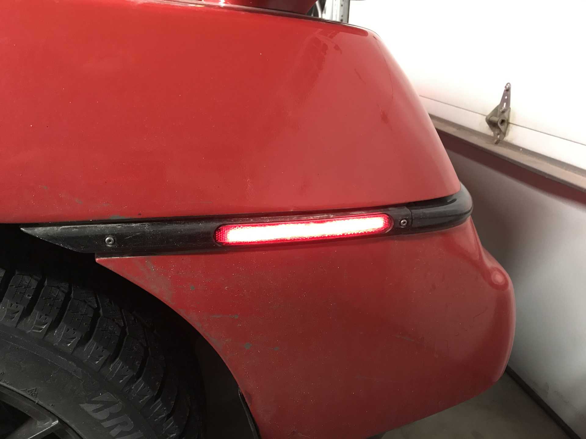
I decided to replace the side markers with LED lamps and discovered this isn't as simple as I expected. The rear lamps are not a big problem but the lamp strips are rated at 12V and will burn out if the current gets too high. Modern engines usually output between 13.8 and 14.2V which will make the LEDs too bright and kill them quickly. I added a series resistor of about 47 ohms 3W and that lowered the current and voltage to give me the brightness I wanted. Note the rear wiring is polarized, hooks up only one way. However the lamps will dim significantly once the engine is stopped since the resistor isn't needed with the battery voltage dropping to about 12.5V resting. I bought my LEDs from VETCO.NET in Yellow & Red, about $5-$10 per strip. They have bridge rectifiers, resistors & zeners too. Cut the end of the back of the fixture and slipped it in. Used heat shrink-tubing for all wiring and then potted with silicone RTV.
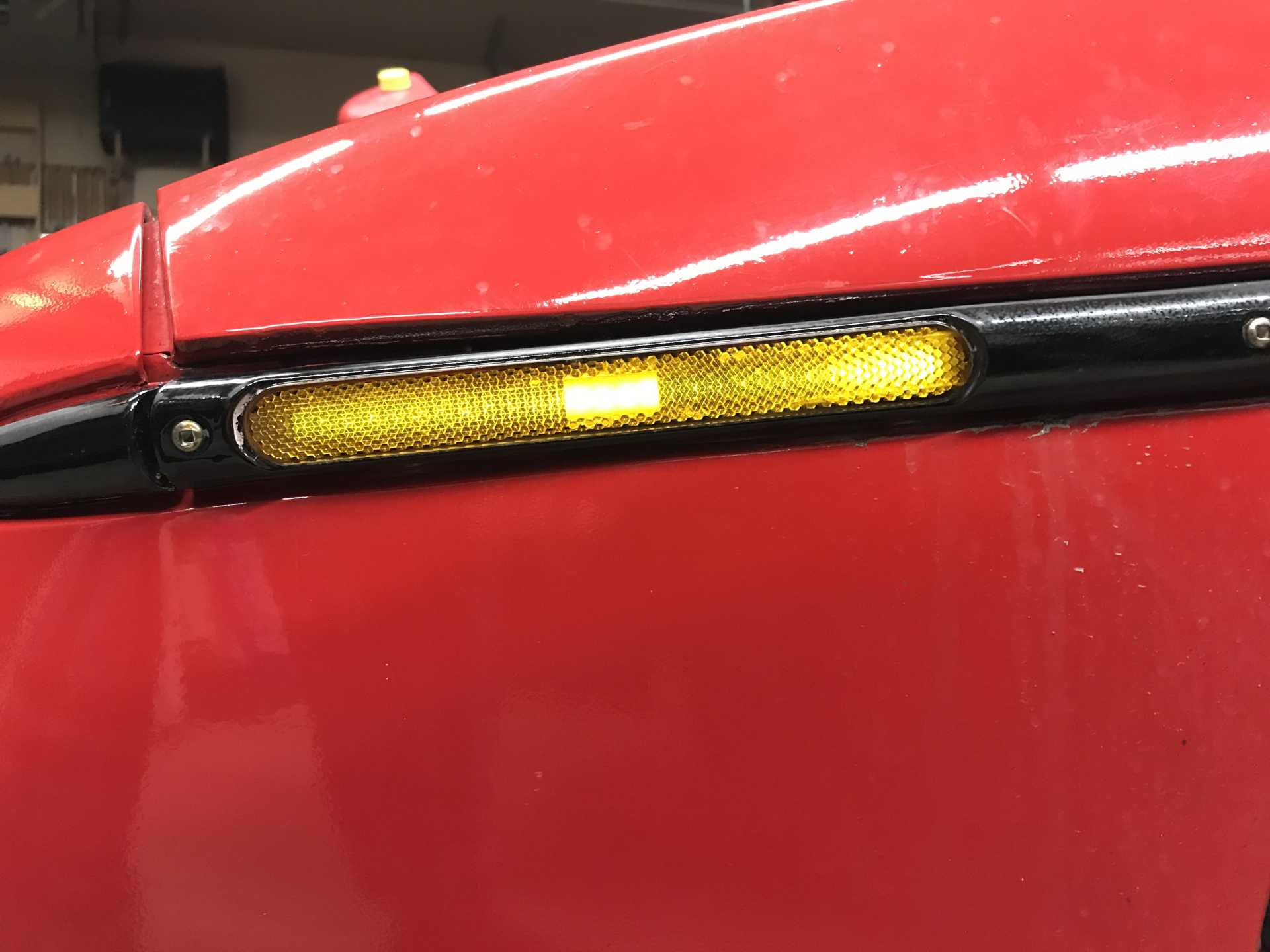
The fronts proved to be more difficult since the original design has current flowing in both directions depending on the parking lights being on. When the parking lights are off the currrent flows normally and all is well, the side marker works in unison with the turn signal lamp. But turn on the parking lamps and the side markers are now on normally. Using the turn signal requires the side marker to be OFF when the Turn Signal lamp is ON. The wiring uses a different circuit that runs current in the opposite direction. LEDs don't like that. One solution is to add a relay to each turn signal lamp and wire that up. But that's a mess.
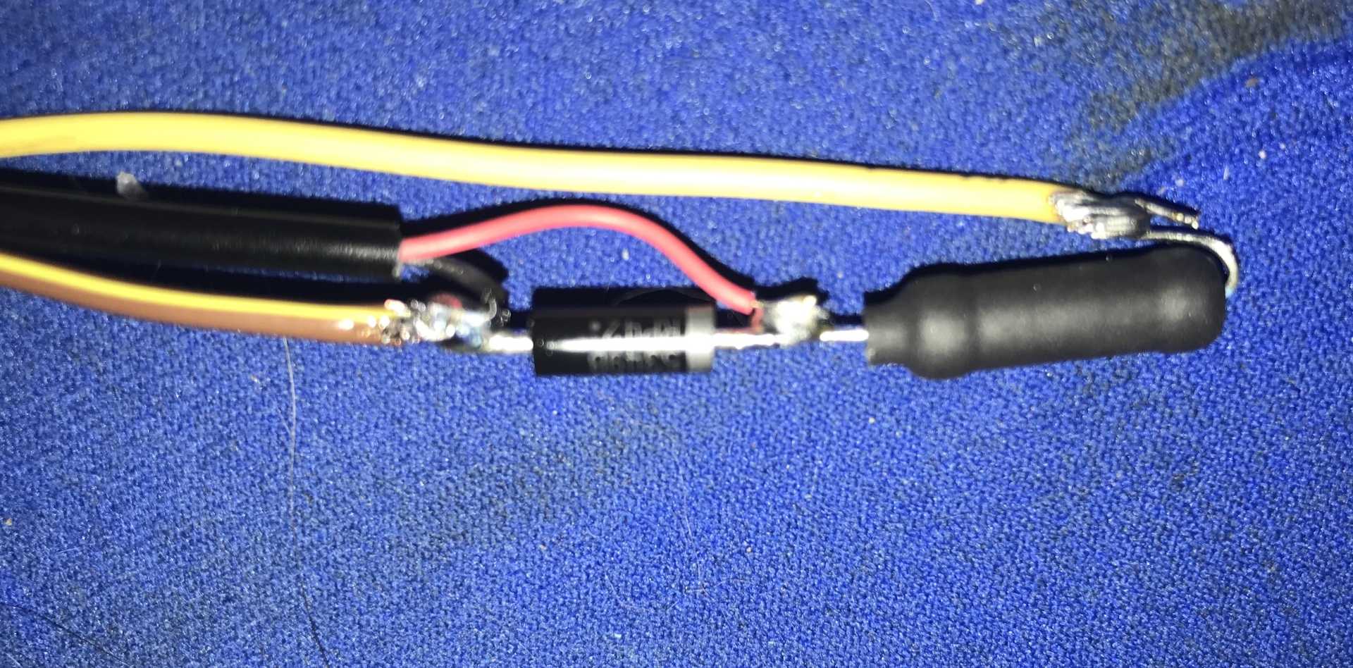
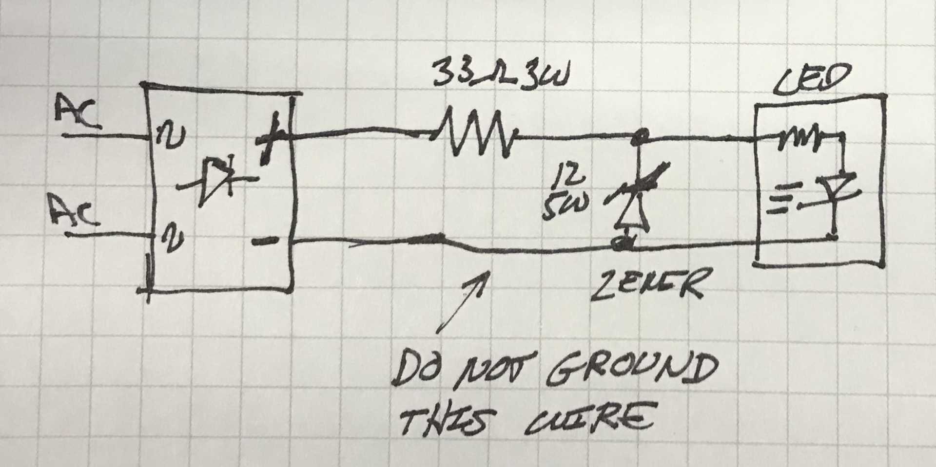
So I added a small SMT 2Amp rectifier bridge to each side marker strip. The AC inputs to the bridge come from the car's wiring harness and the DC output goes to the LED strip. The diodes make the power is always has the correct polarity, but they cause another problem. The bridge now causes the 14V power (with engine running) to be about 12.8V after the bridge (diode drop x 2 is about 1.3 to 1.5V) Rather than use only a resistor I decided to use a 12V Zener diode as a simple voltage regulator. Zeners are different in that they are hooked up backwards (Anode to common) and will not conduct until the voltage is above the zener rating. Once that voltage is reached the diode conducts (in the opposite direction). So you need a resistor before the diode to limit the current. But that will be lower resistance, about 24-33 ohms in my case. And no relays to fail or mount. The wiring from the car harness is not polarized so hook up either way to the bridge rectifier. But do not ground the output negative going to the LED lamp strip.
Front wiring from Bridge to LED strip. Black & Red go to strip, Black is negative Yellow goes to Bridge (+) Orange-Yellow goes to Bridge (-)
Schematic of Front Wiring
The front turn signal lamps continue to complete the side marker circuitas in the original design. I might not work right if these incandescent lamps were replaced with LEDs but I haven't tried LEDs in the front turn signal lamps yet to check this out.
Front LEDs look washed out from this view. Reflectors in the fixture cause this, also car is not running.
Rear LEDs look better Might need to lower the resistance more. The Zener only clamps the brightness to keep the LEDS from burning out.
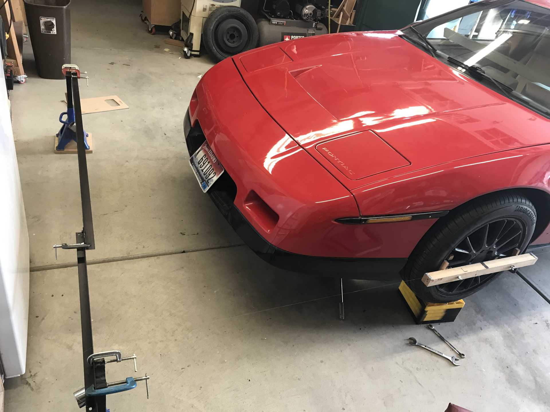
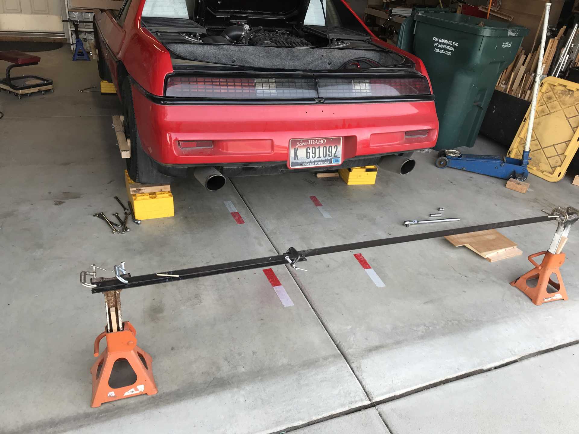
Next it was time to do a better job of front end alignment and to align the rear for the first time (probably in 25 years!) I made an alignment jig that mounted to four jack stands, held on by C clamps. These were used bed frames cut to length with notches for the strings. The width was set to match the wheel fixture centerlines to simplify the mesurements. I had some 4 pound monofilament to run as the "string", the thinner the better.
Front and rear jigs in place
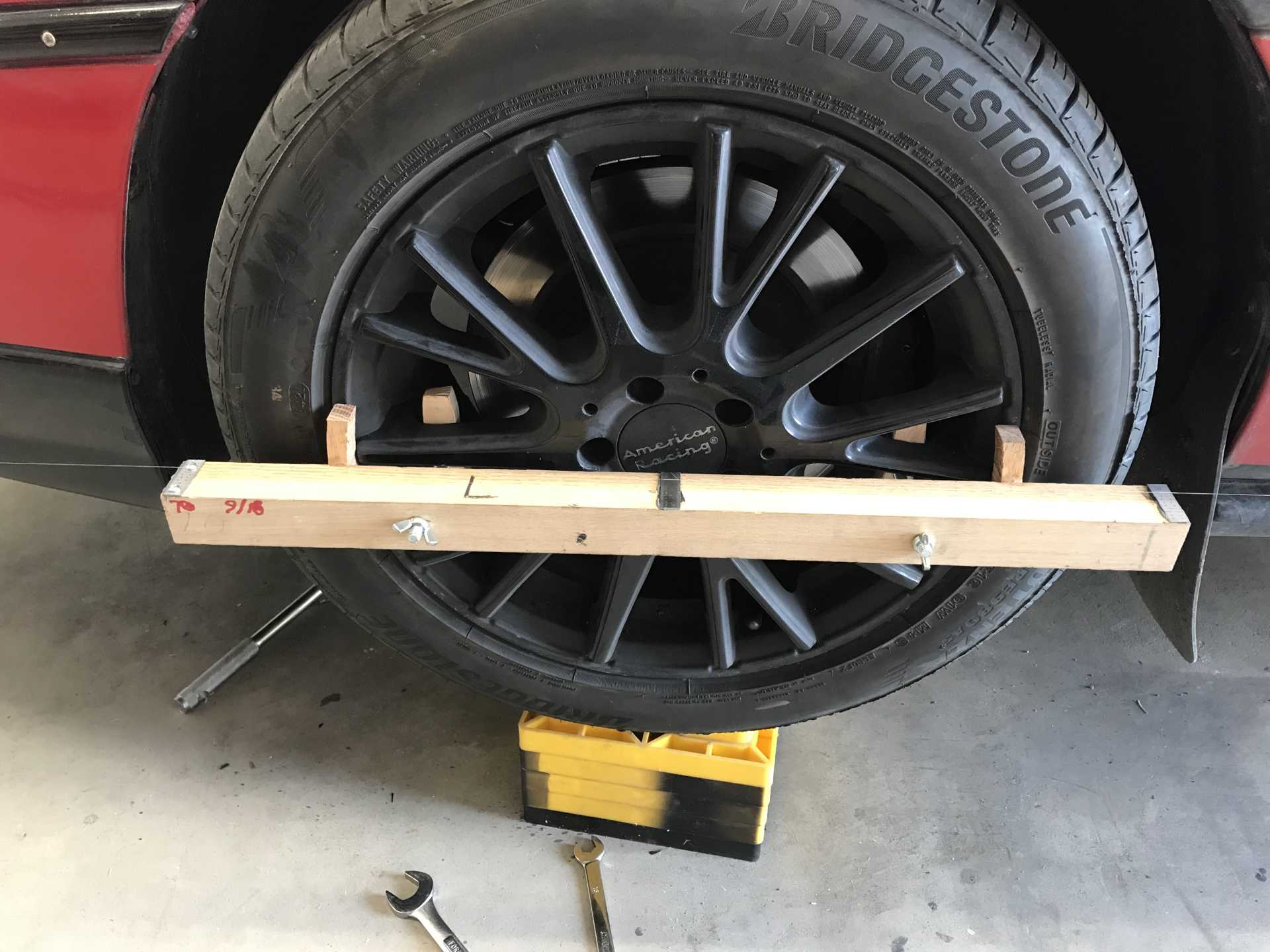
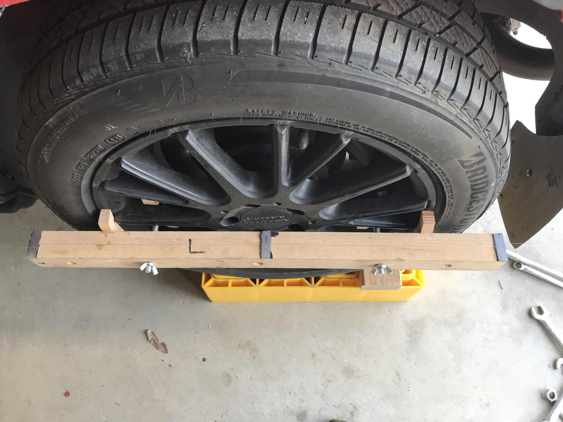
For each wheel I built a measuring fixture that bolted to the wheel. I used cut-up 6" scales for measuring at the center and ends of each wheel fixture.
The first thing I discovered was the rear toe-in was almost 1/2 inch on each side. No wonder it ate tires for breakfast and didn't want to go in a straight line at highway speeds.
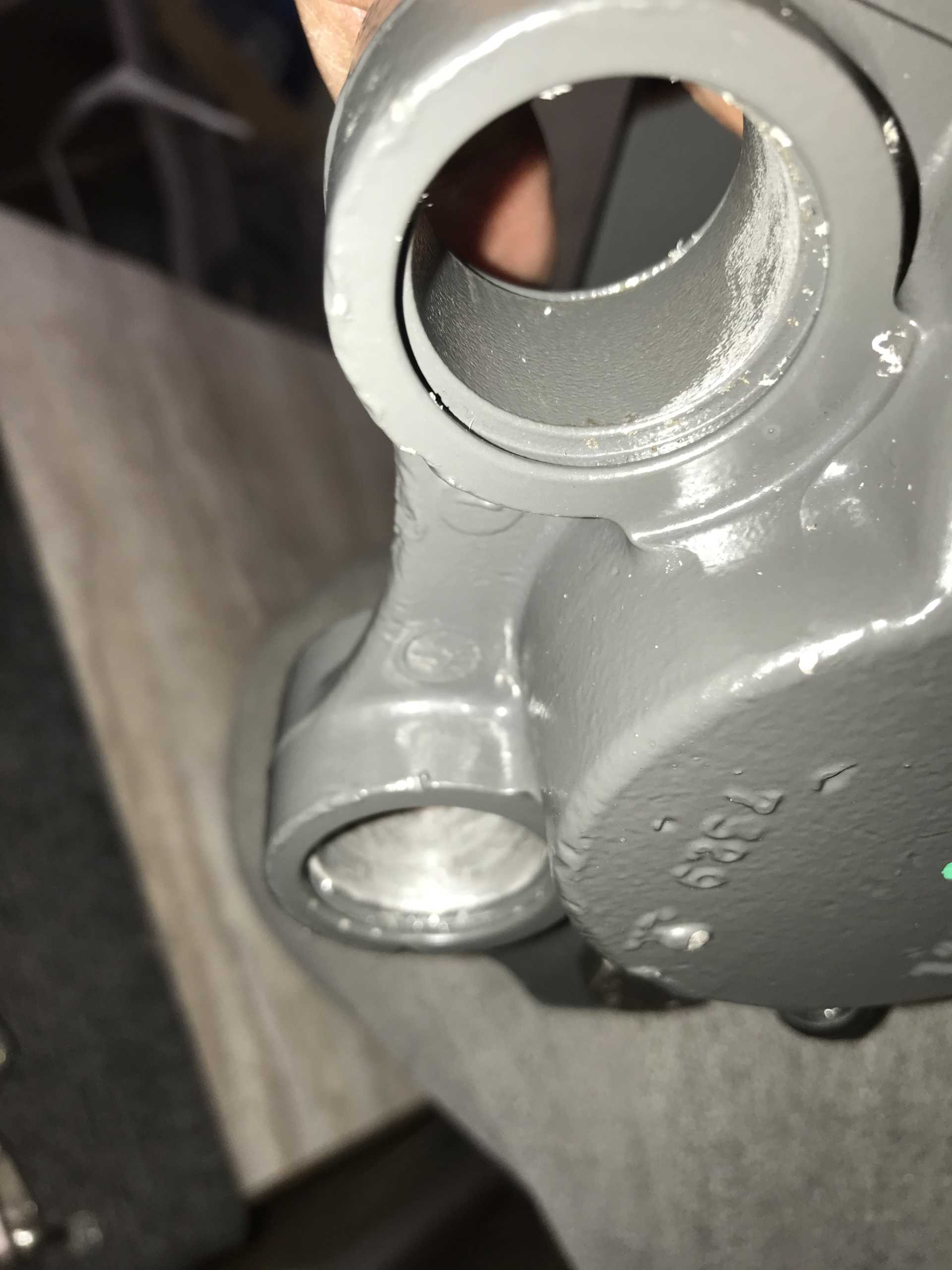
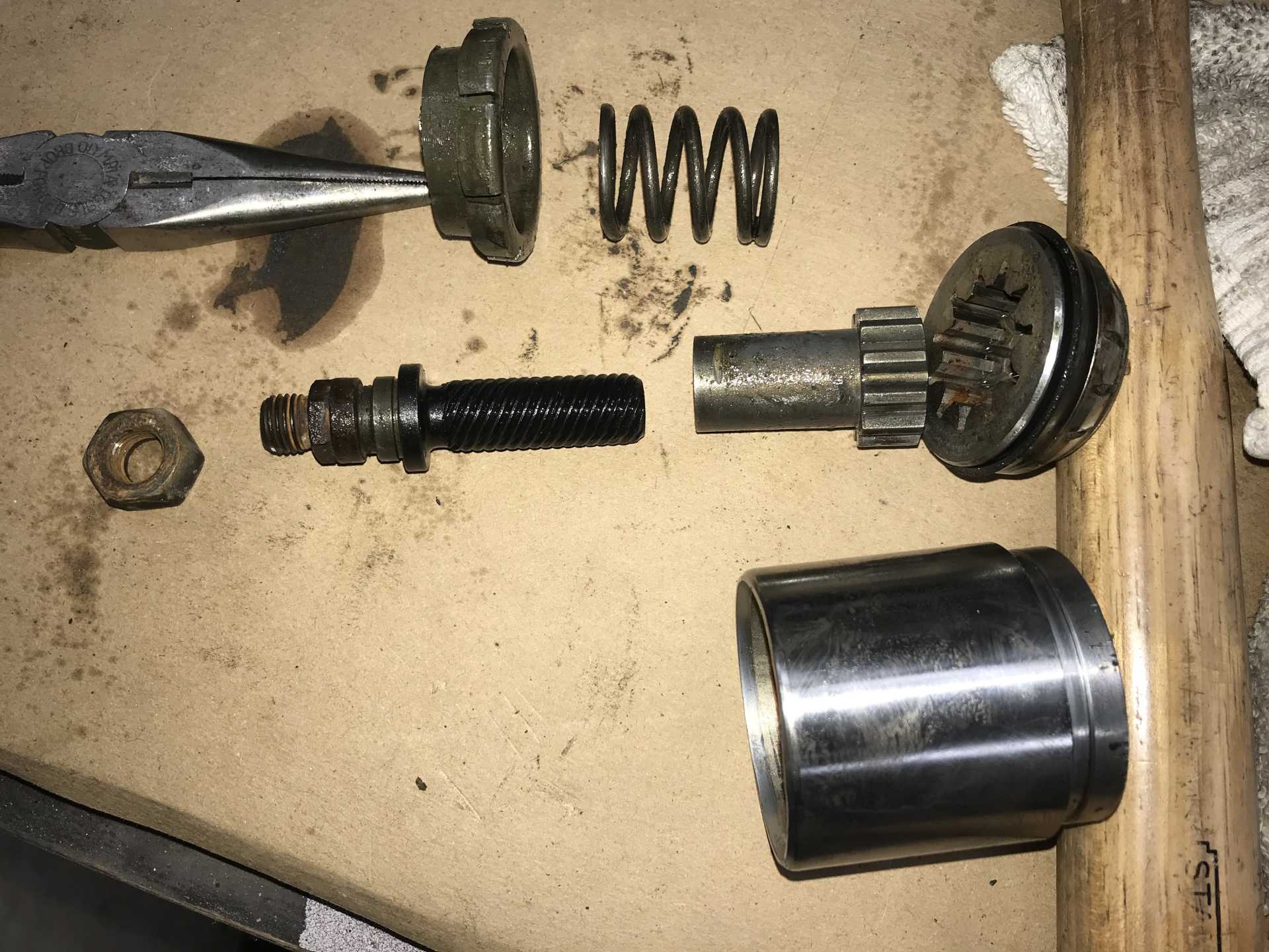
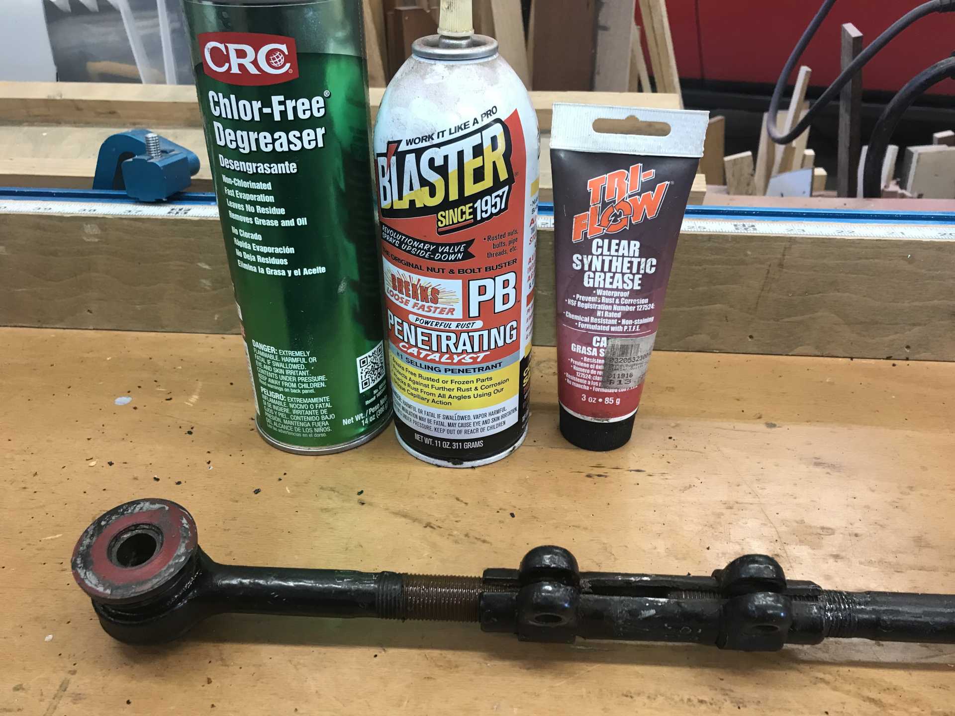
The rear toe adjusters needed to come off to be unfrozen. It took an hour each to get them apart and cleaned. Plus an hour to disassemble and reassemble after.
You needs good chemicals to work on these ancient adjusters.
When adjusted it is much better with a slight right pull. It also doesn't want to be skittish in the rear any more. I'll address that pull later and give the front a bit more toe-in since there were more pressing issues to deal with.
Getting ready for the NorthWest Fiero Fest and... the right side CV joints fail. Crap.
[This message has been edited by MikesFirstFiero (edited 02-20-2025).]
The RR CV axle began to make noises so it's time to replace the joint(s). To do this I buy an Impala axle, if the inner joint is bad, or try to find a real Fiero CV outer joint, otherwise buy a Fiero axle. The problem is the non-OEM Fiero axles are not always able to be disassembled. The ones O'Reilly sells fall into that type. The outer joint is not intended to be removed. It has no accessible C-ring to release the joint. Luckily there are still some original CV joints (sometimes) available. If there is another outer that would work I'd like to get a few. Eventually I did find a for-real outer joint a few months ago and ripped the two-year old axle out.
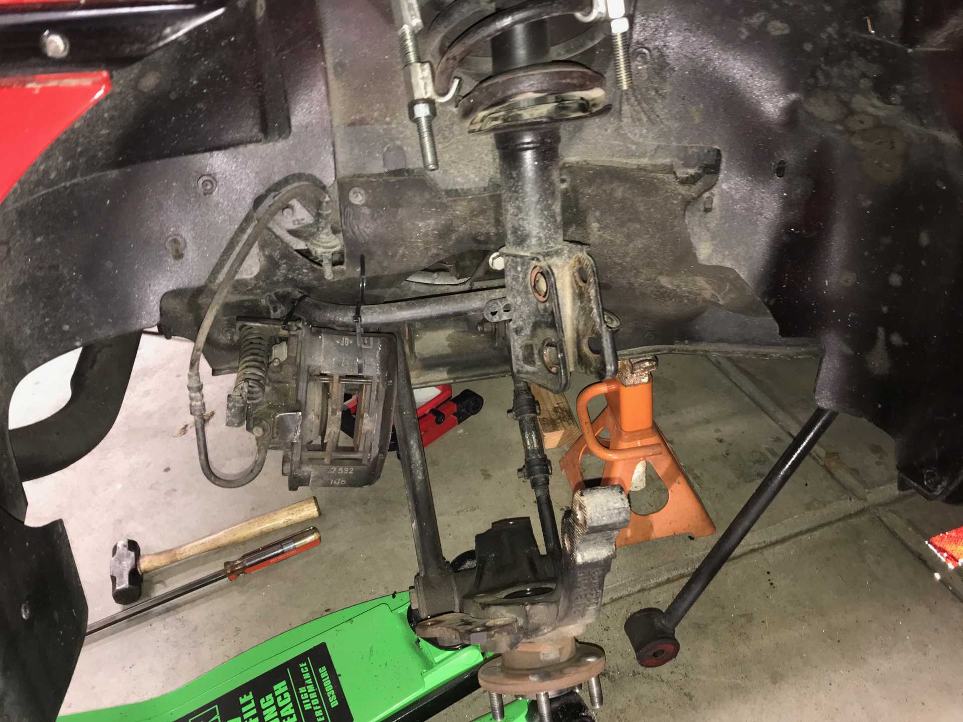
I've been here before. Now have a new Harbor Freight Daytona Low Profile Long Reach jack that is much better for getting under the car. The front is lowered and this makes it much simpler to lift.
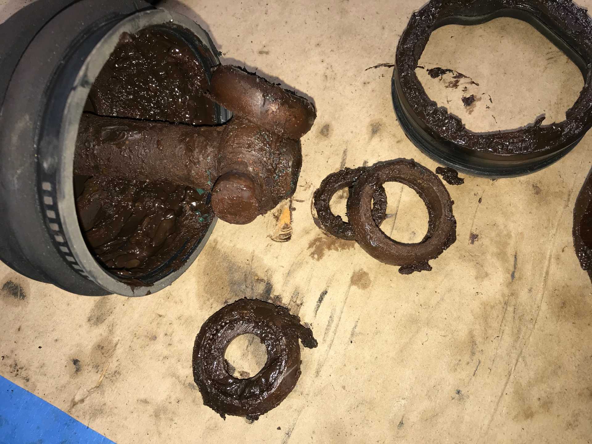
Failure was by water contamination. The boot openings for the axle just did not seal properly with the expected results. The inner had completely failed while the outer might have been salvagable but I replaced both. The inner is totally gone
And the outer is not happy either
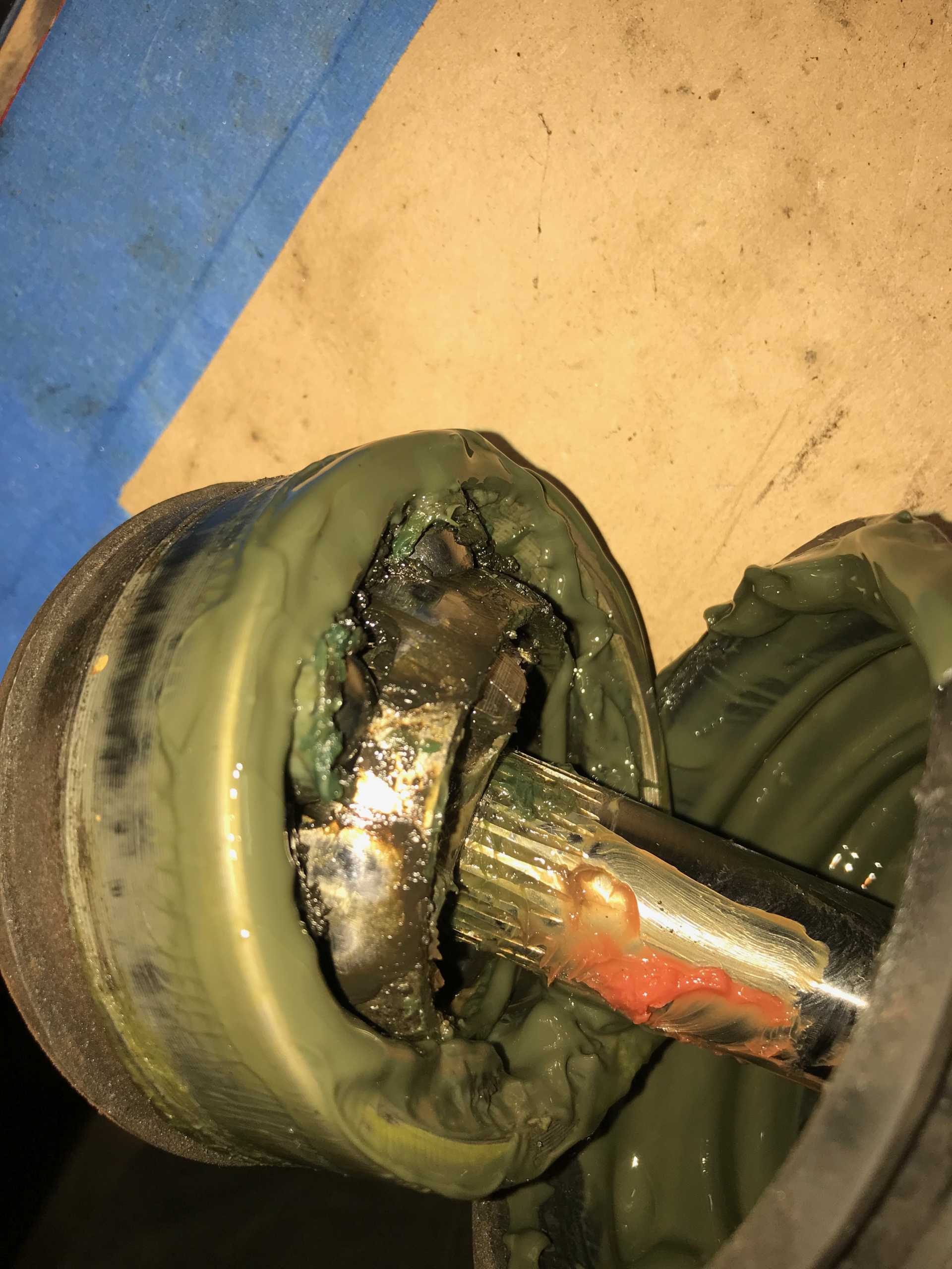
Another concern is the axle splining fits too loosely to the tripod hub. This causes a noticable Klunk sound and the impact will eventually damage both of these parts. Then I found a product that can fix this called Locktite 660. It is intended to solve this exact problem. It's expensive at $60 for a 4oz tube but what the heck. It is a paste that hardens over 24 hours is a permanent fix and can be removed by heating to 500F. I cleaned the shaft and hub and applied enough (about 1/2 oz) to fill all the splines, assembled the pieces, snapped on the C-ring and let it set overnight. Next day it was setup solidly. (Writing this now after 9 months it has been dead quiet).
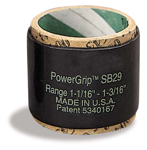
The boot leakage problem has concerned me so from the start. The clamps simply don't fit well enough to the axle end to properly seal. The seal on the CV end however being a bigger diameter has not proved to ba a problem. I dug around and found that Gates makes a Heat-Shrink hose clamp in different sizes with a grip range of about 1/8". These are substantial and are shown being used on truck radiators. At about $5 each they aren't cheap but the problem needs a better solution. Being a polymer ring in tension they should be able to seal if the rubber/plastic boot shrinks in the winter and to provide constant pressure since there is no overlap joint of a metal clamp.
Gates SB Clamp
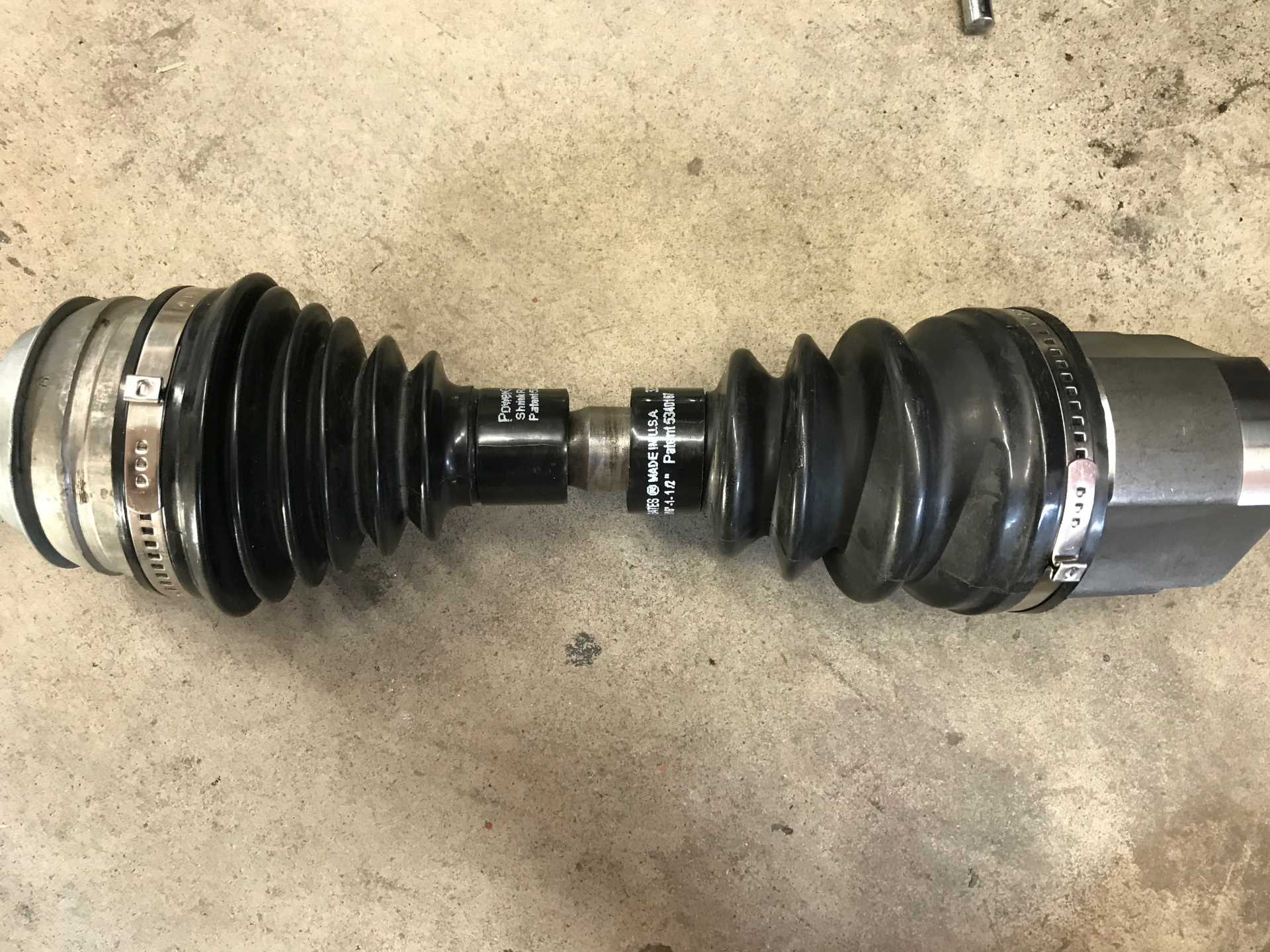
I bought a few and popped them on the shaft & boot before final assembly
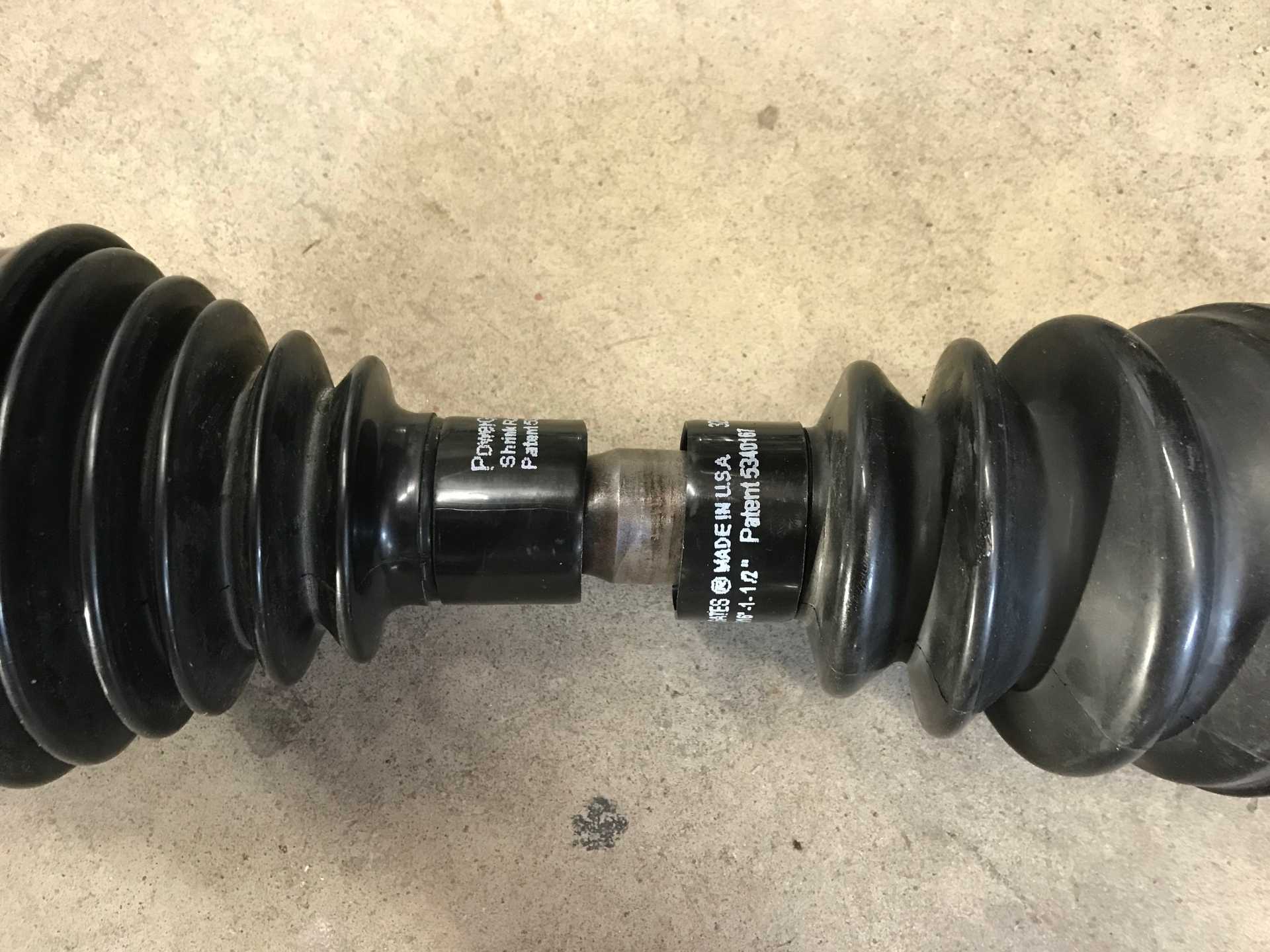
A Closer Look Before Shrinking. They are almost a tight fit over the boots
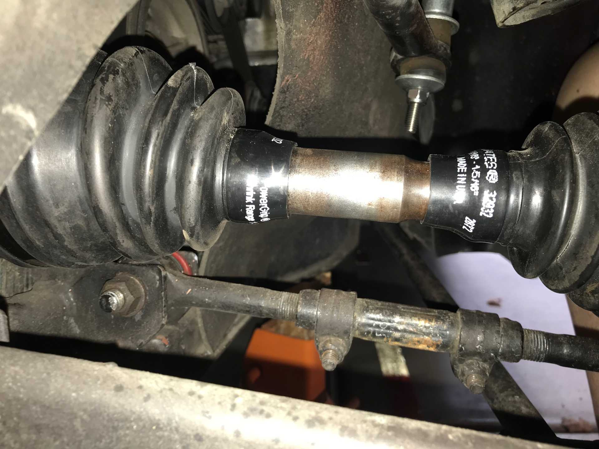
Then I got out the heat gun and shrunk them
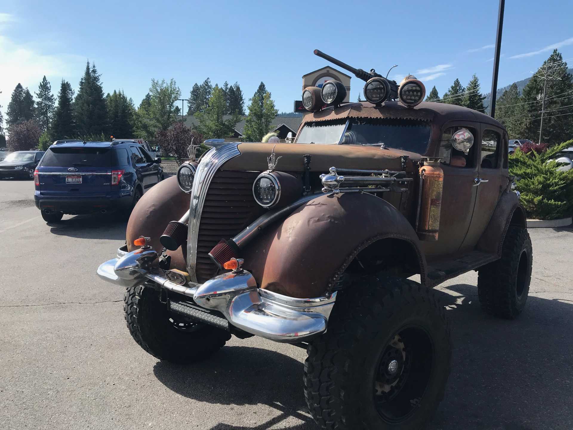
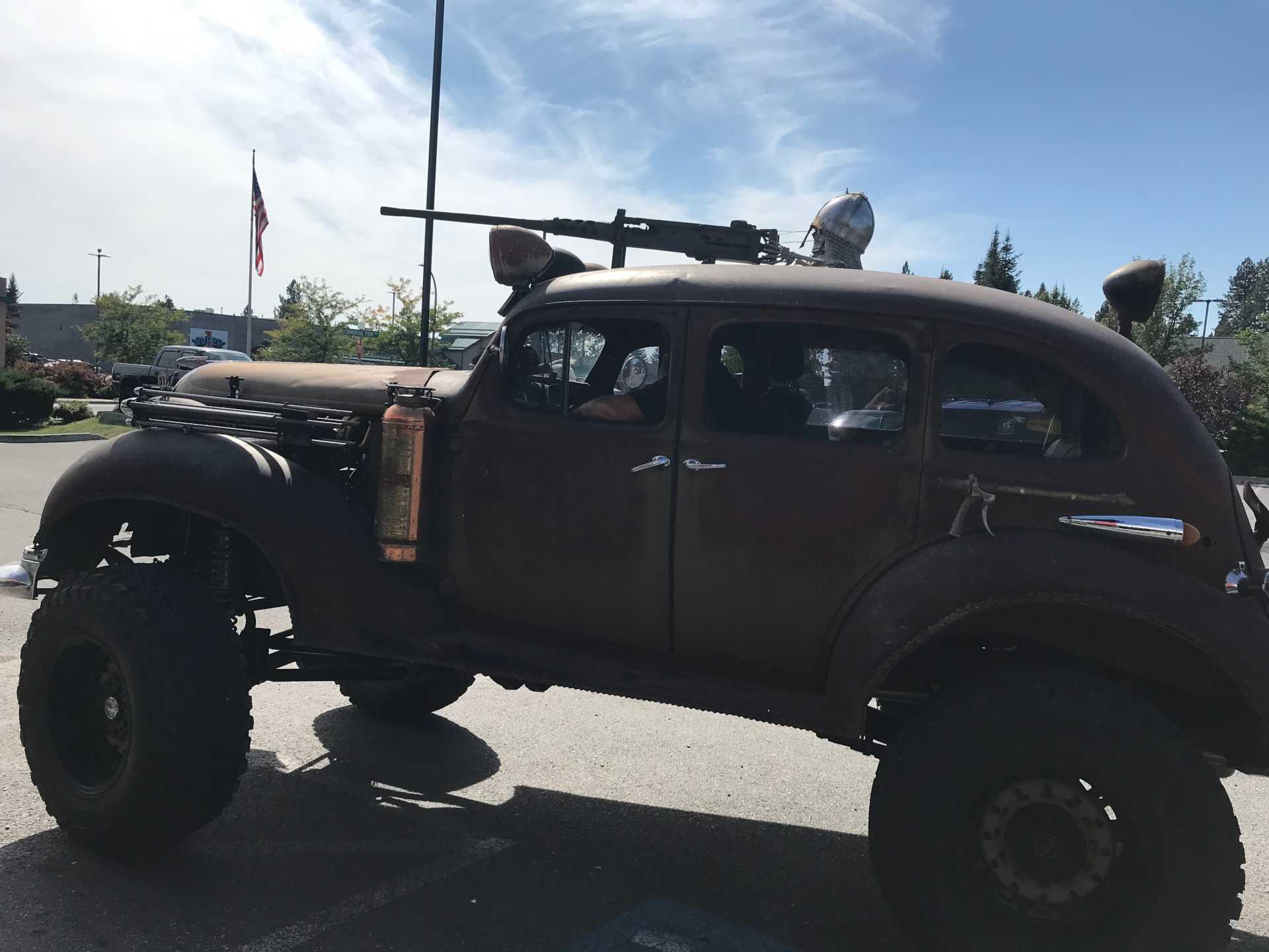
Sometims you see some unusual cars on the road. This showed up at the store the other day.
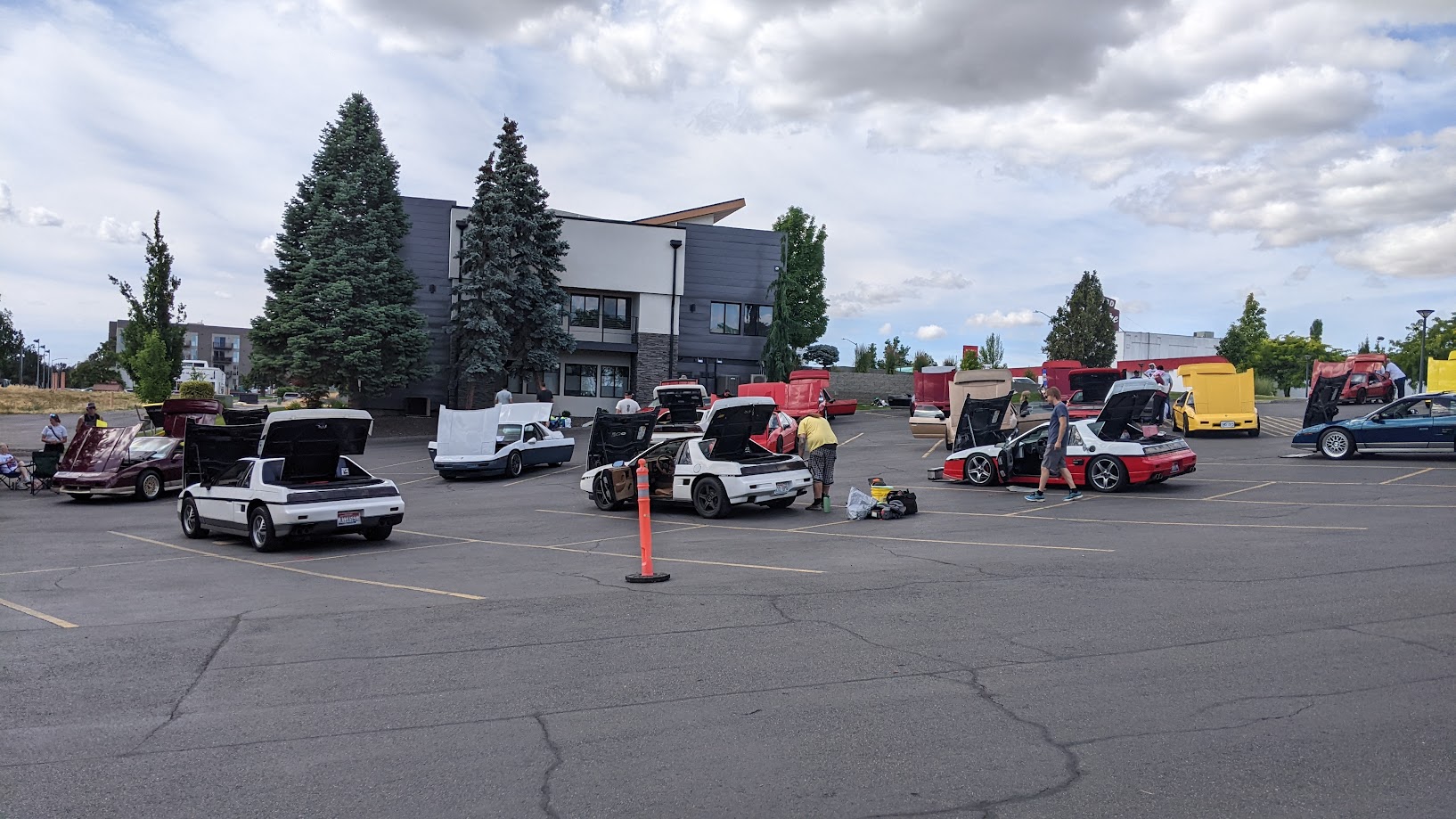
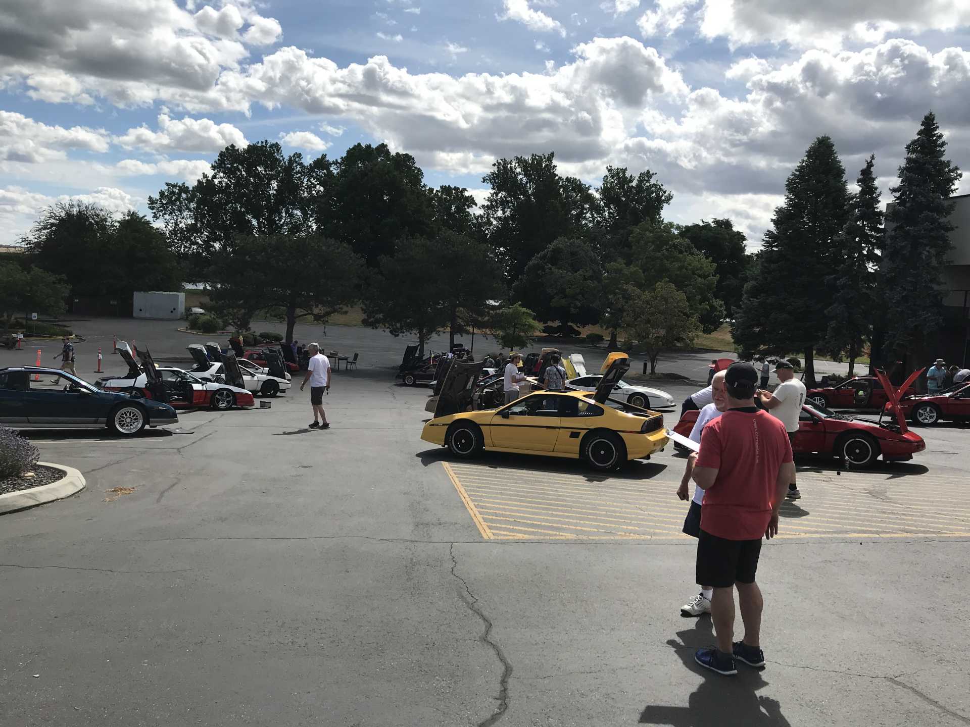
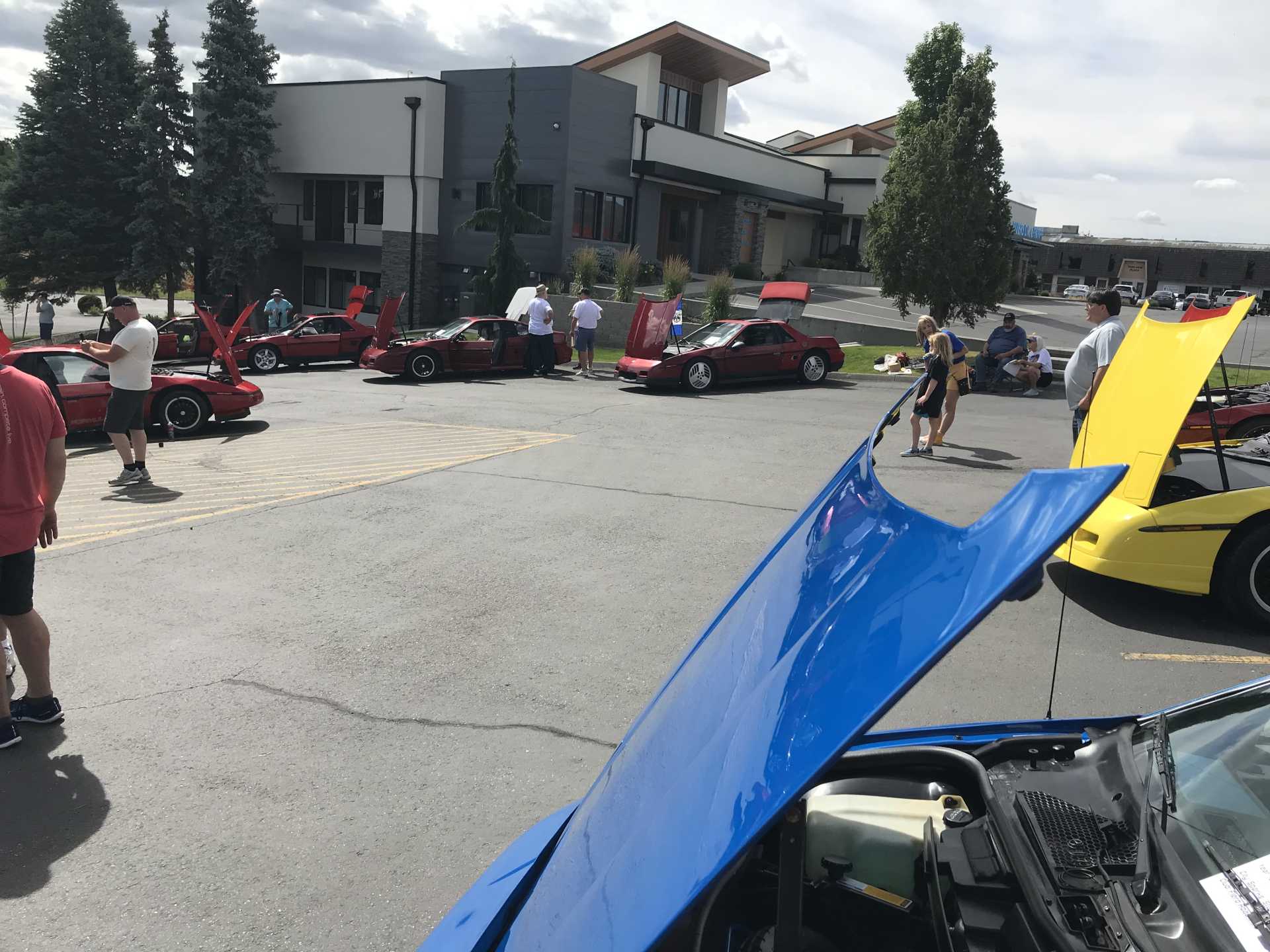
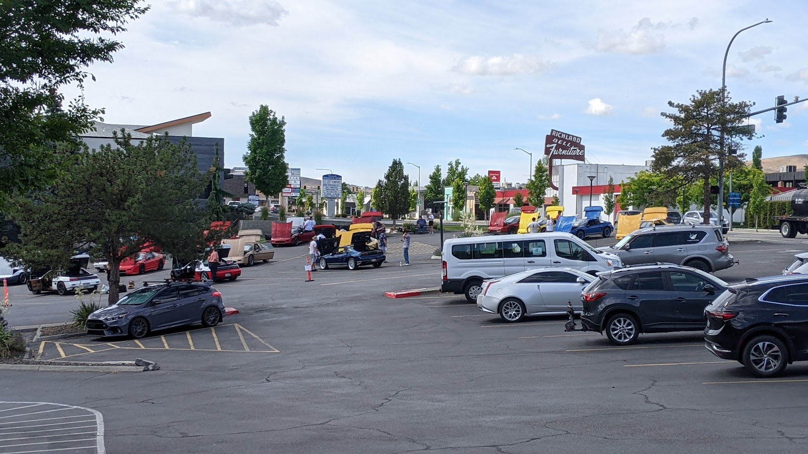
After putting everything back together It was time to head down to the Tri-Cities in Southeastern Washington for the NorthWest Fiero Fest. About 35 Fieros were displayed with a great variety of ideas of how to present a Fiero. Lots of engine swaps, interior and exterior modifications, paint schemes and lighting solutions were on display. A really fun gathering with endless talk about our favorite car.
A couple of photos of the cars on display.
And I Never expected this... I am truely honored to receive this award.
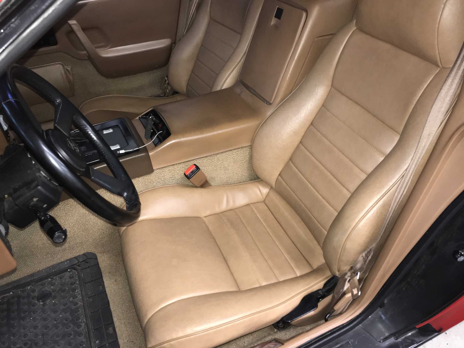
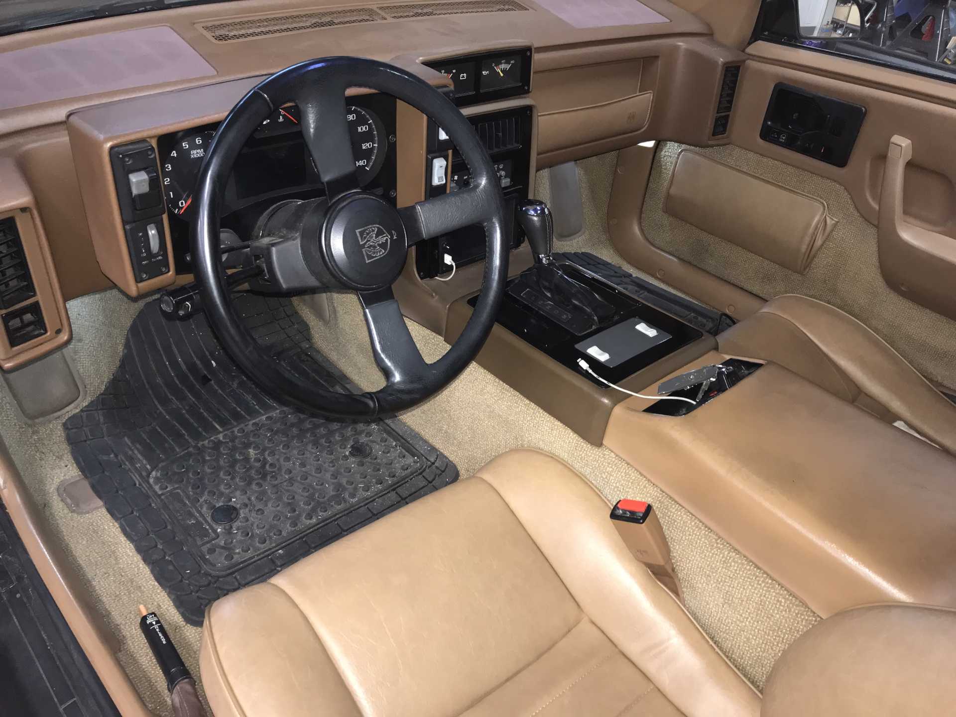
Going to the Fest did show up one glaring issue with my car; the original interior was beyond help. And then the fabric began to wear out so it was time to contact Mr.Mike's for a set of new covers. Calling them covers is actually undervaluing what he provides. His products are a complete upholstery product that provides everything you will need to have a professional-quality interior. The customization options are seemingly endless and the materials and workmanship are first class. My wife is a Tailor and was impressed by the details of how the covers were constructed. Mike provides a product not available anywhere else at a very reasonable price. Be sure to read everything Mike provides and follow his instructions to the letter. Plan on about 2-3 hours to do each seat, have a clean work space and wash your hands before starting. And be careful of sharp tools when workinglest you kick yourself or even worse the covers!
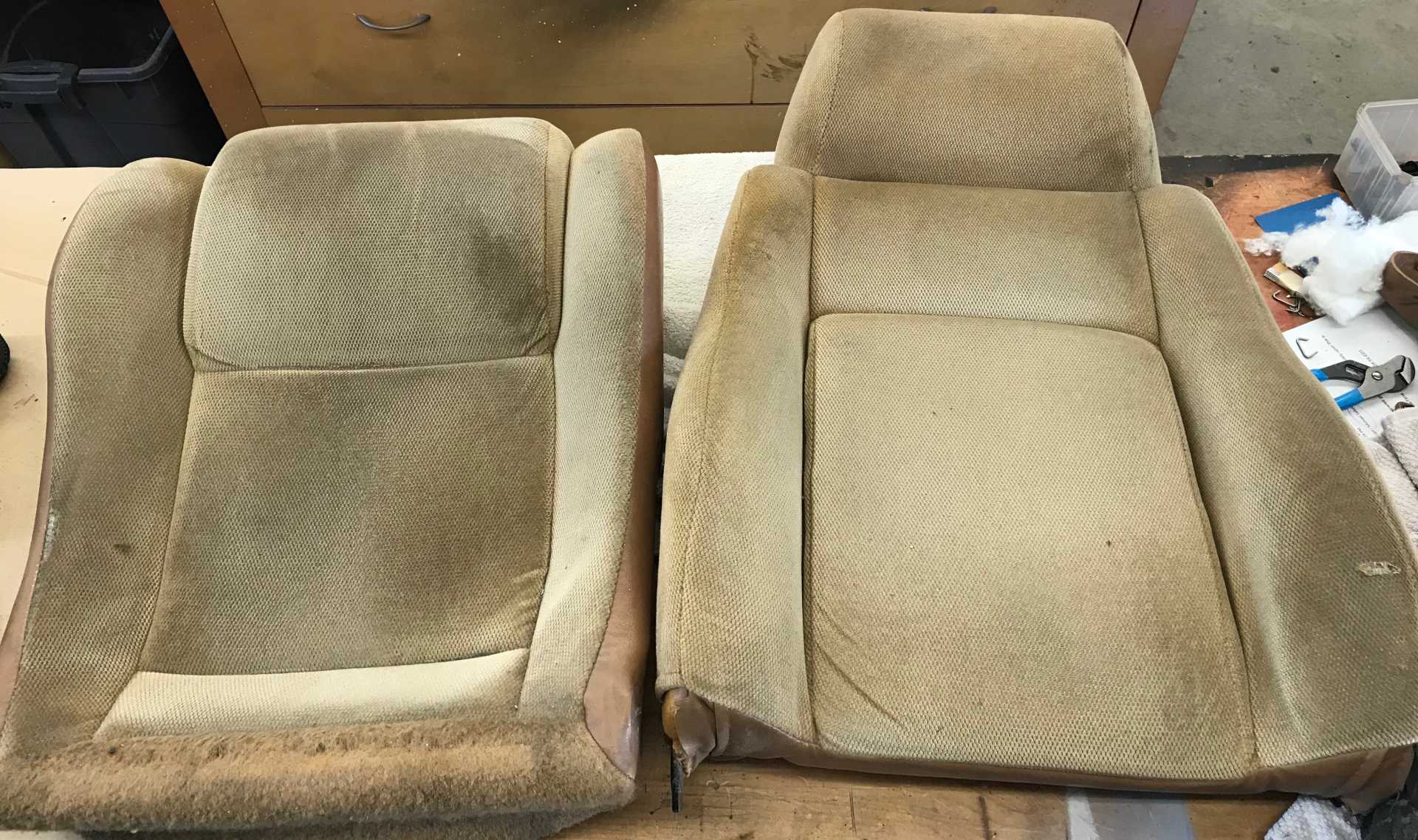
What the original seats looked like
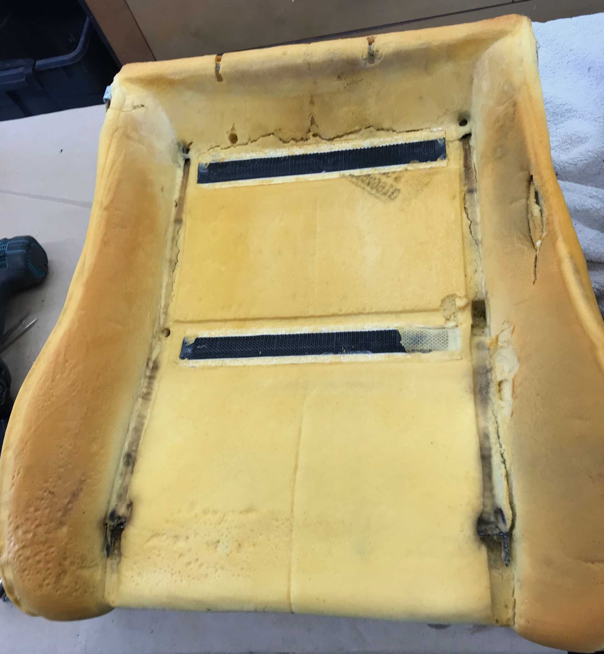
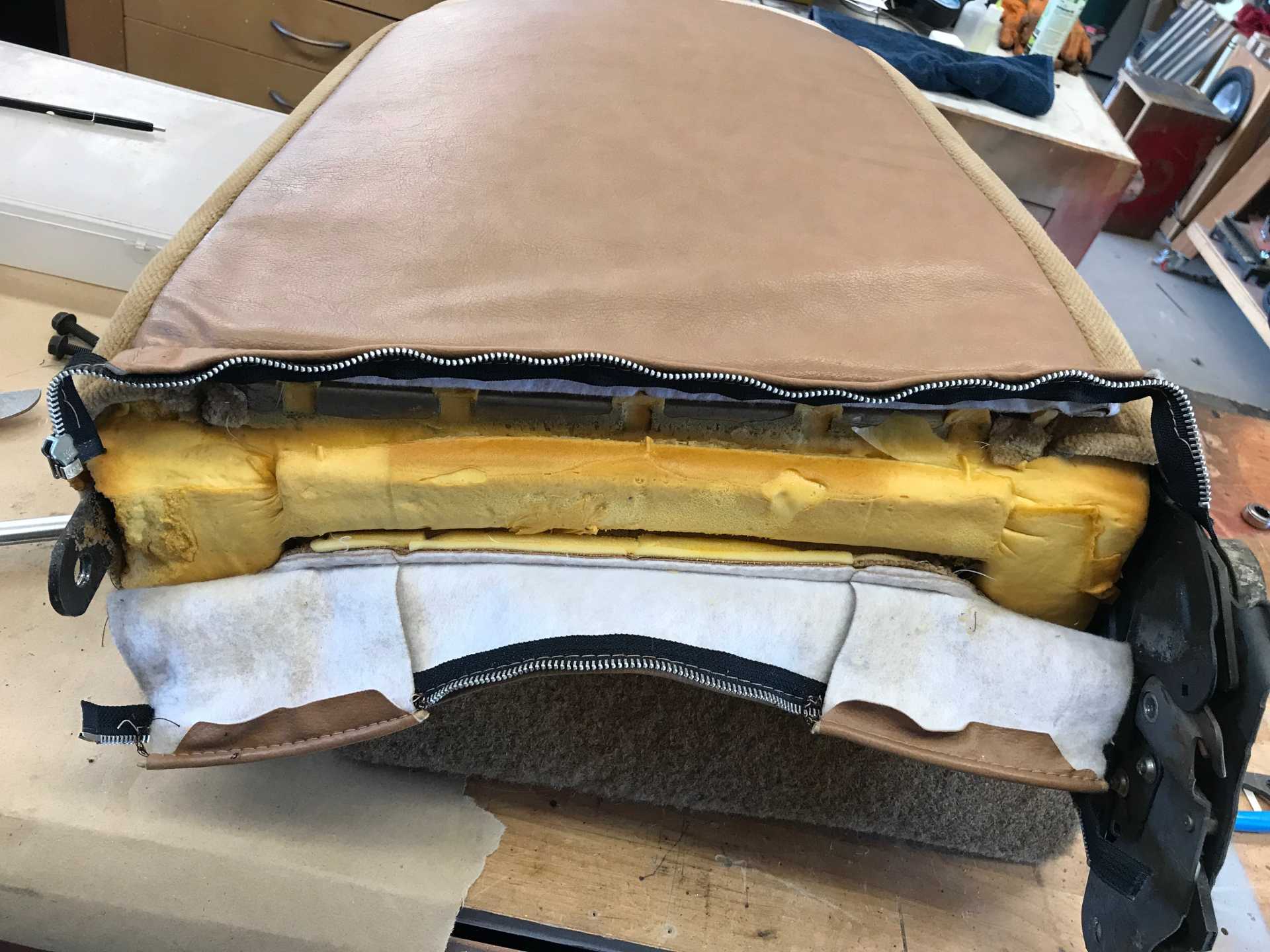
The driver's seat bottom. Note the cut foam where you exit the car. This is caused by the sharp pan edge below the foam. I added a length of 1/2" heater hose over this edge to reduce the pressure when you sit on it every time you exit the car. I also added some replacement foam and then installed the batting and cover.
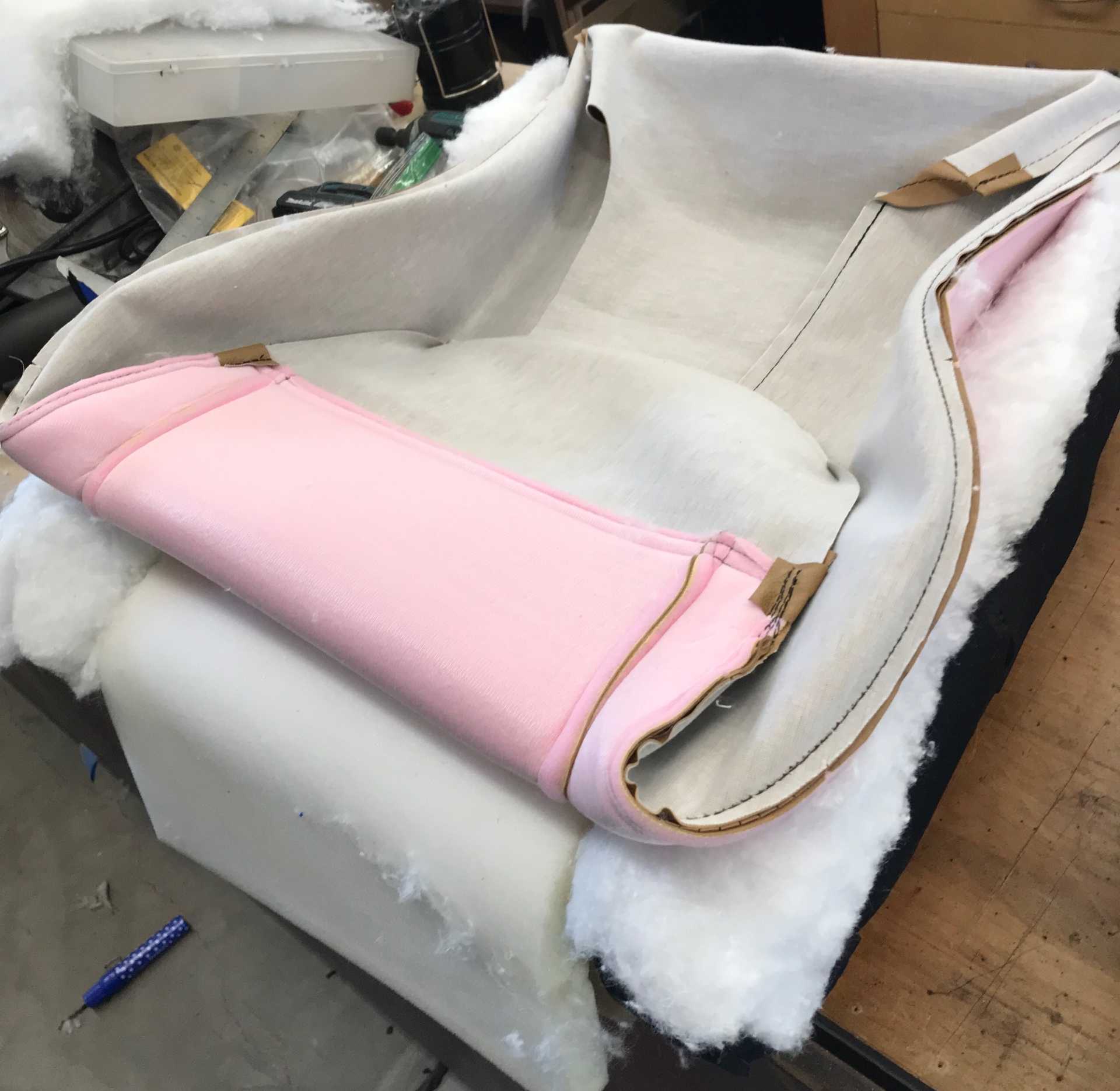
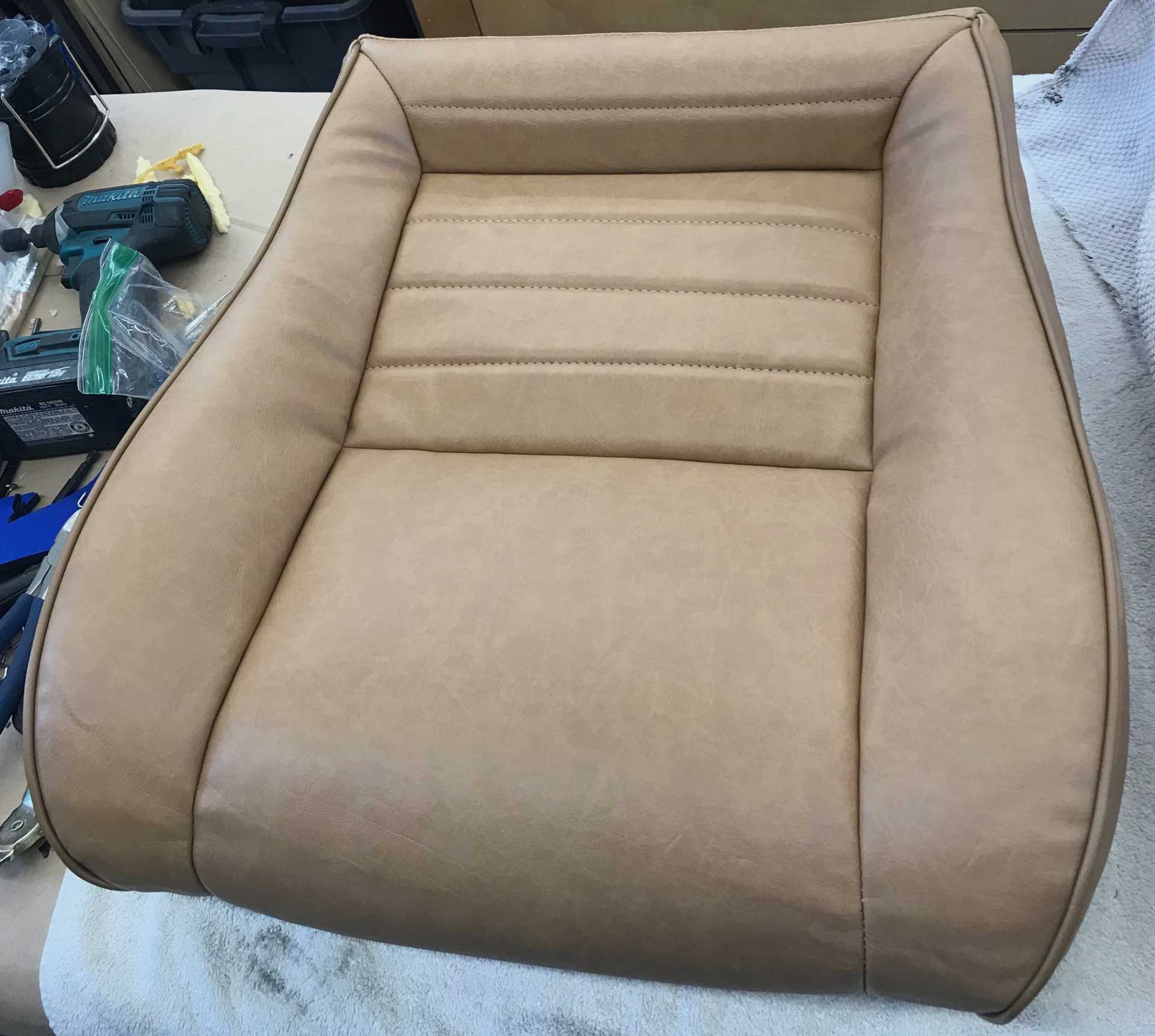
Next you add the new bottom cover and apply it over batting to remove wrinkles. Takes a fair amount of pulling, tugging, smoothing to get it neatly in place.
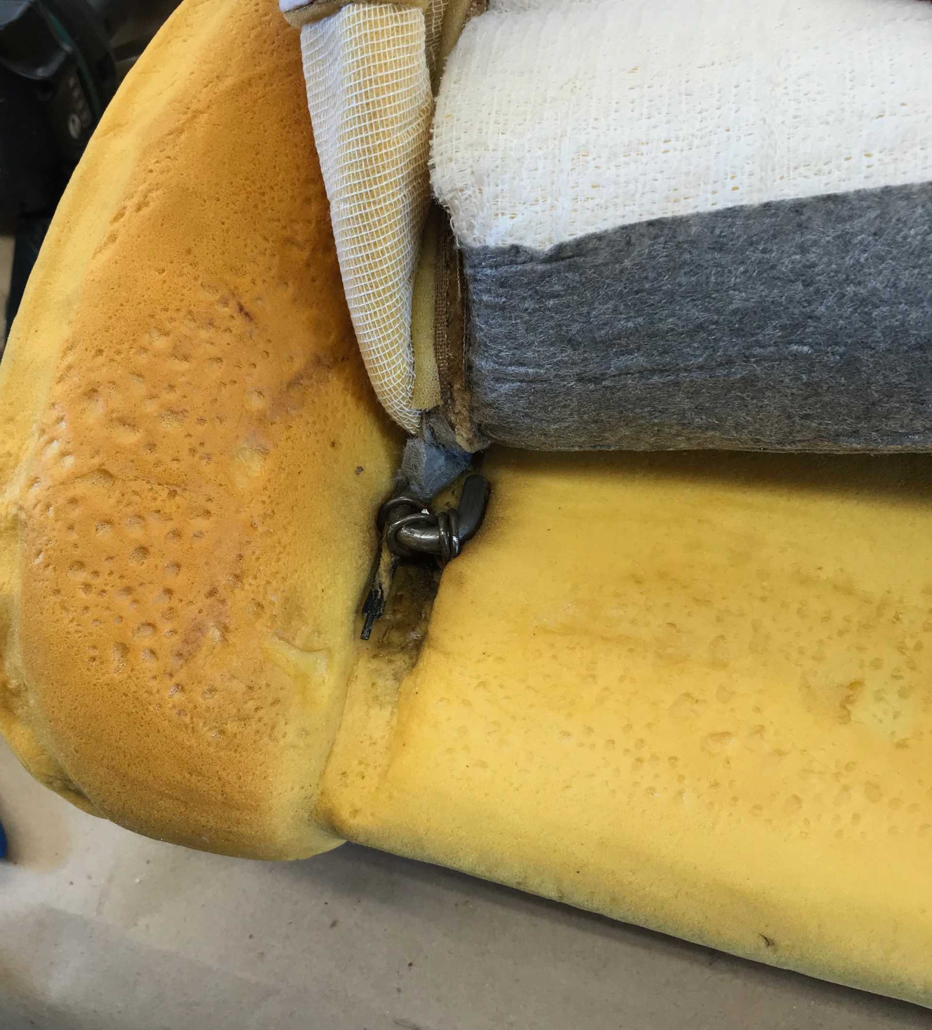
The edges of the inner seat cushion are ositioned by two of these steel rods that are held in place by hog rings. A very effective solution to give a professional look. They aren't easy to get in place but work on it and you will get it done. Be sure the rod ends are in the right place at the back, under the seat frame.
And this is the finished result. Those minor wrinkles will be gone in a day or so. Don't skimp on the batting, plan on using 100% of what is provided in the kit. You will also become adept at installing Hog Rings with the pliers Mike provides. Those hold the cover firmly in place.
The seat back slips on with some (lots of) pulling and tugging too. It also has retaining rods to be installed and has a zipper to close it at the bottom.
And the final result is Great! These photos were taken six months after installation and they look wonderful. I chose the Mercedes Vinyl material and really love the texture, color and feel. Could not be happier.
Now that it is getting hot it's time to look at making the A/C work.
The string alignment method works quite well and I worry that today's mechanics have no clue about what it takes to set the front suspension up. Plus it's cheap to make and not difficult to do. The car is on blocks to make it easier to work on. Those Gates SB axle clamps are still where I put them too.
Time to try to make the Impala A/C work with the Fiero. The Fiero started life as an R-12 unit. The system was totally leaked out after sitting for more than 10 years. But with the Impala LFX there is no simple way to replace the compressor with the old 2.8L unit. Being 30+ years old it probably needed a complete overhaul. What about the Impala compressor? Can it be used? Well it is quite different, it uses R-134a in some cars and R-1234yf in others and it will take some pipe-bending to clear the cradle and alternator and oil filter.
R1234yf became manditory in 2021 with 134a being obsolete for newer cars. The chemical formula for 134a and 1234yf differ by one carbon atom. The structure of the molecule do differ somewhat. Since they are very similar in composition and characteristics the compressors for 1234yf and 134a are almost identical in pumping, pressure and heat ransfer characteristics. As for the refrigerants 134a costs $12/12 oz. can, 1234yf costs about $65 for the same amount. 1234yf is more reactive so it must be changed more often since it reacts with contaminants in the refrigerant oil. This is sounding more like a money-making planned obsolescence scheme with 1234yf costing 5 times more and needing replacement more often. As a result if you own a post 2020 car there are charging port converters on the market so you can swap (illegally) to 134a. Since R-12 was out of the question, I decided to upgrade and use R-134a.
The Impala compressor is a variable displacement design that has two electrical connections. One connection operates the compressor clutch and the second operates a displacement solenoid. The solenoid in the Impala uses Pulse Width Modulation (PWM) to adjust the valve position and the amount of cooling to deliver. Well I don't have any means of controlling that solenoid from the car's 1988 electronics. To do so would require the complete Impala HVAC controller and countless hours to make it work. Damn. So what I did was by trial and experiment determine that if a constant 6V is applied to the solenoid the valve will be opened enough to cool the car. Adding a branch wire from the clutch power feed thru a 10 ohm 5W resistor gives the solenoid the 6V (about) needed. So far it has worked once al the leaks were solved. I'm told other LFX compressors for 2018 (camaro?) are the older on/off control type, but I didn't want to buy one to find out is somehow incompatible with the FWD LFX configuration.
So much for the controls, refrigerant issues and design considerations. Time to get down to wrench turning.
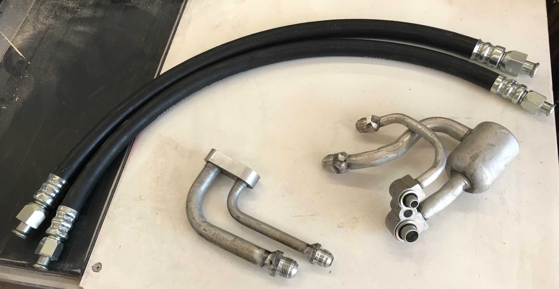
Mounting the LFX compressor is simple, it only goes in one place. There are no adjustments needed. The compressor hose connections look similar to those on the Fiero but are totally different. The LFX compressor pipes were part of the hose assembly which was totally incompatible with the space available. I used my local hose experts at House of Hose in Spokane, WA to make me up a pair of custom hoses that would connect to the Impala compressor fittings using compression connectors and then connect the other ends similarly to the Fiero original hose fittings. Oh, and I'm not sure how long to make each hose so don't crimp the Fiero ends until I get a final measurement. So they did what I told them to do and moved the Impala fittings (per my rough sketches) to try and clear the alternator.
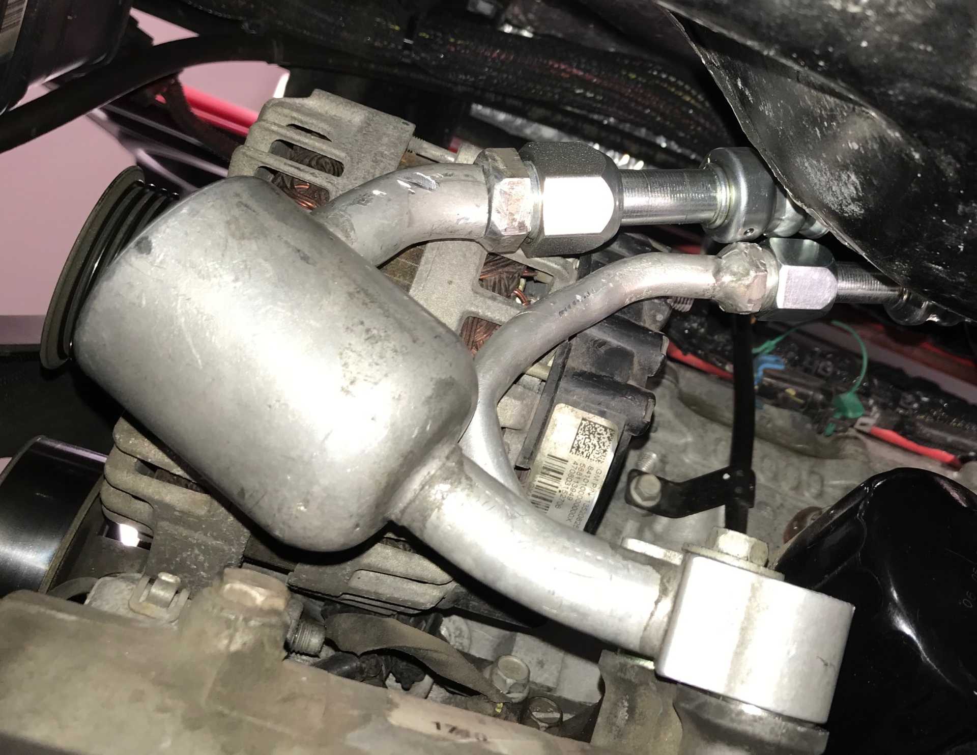
About a week later they delivered the parts. The first problem was the Impala compressor block would not clear the alternator. I got out the torch and bent them until they did clear everything. Connected up the Impala ends and routed the hoses to the Fiero hose ends. Then cable-tied it all up so the hose lengths were determined and the fittings could be crimped on. And by-the-way could you please take a kink I made out of the Impala pipe? The results were great, everything fit correctly but it leaked badly at the Fiero connection to the firewall. That took some new A/C rated washers and two attempts to get it right. When evacuated, charged and checked for leaks it worked with only a partial charge in the system. So load it up with the 20 ounces of refrigerant and I've got cold air. Total cost of the custom hoses was about $350 with tax.
Here are the hoses and the two end connectors to the Fiero and the Compressor
Installed hose connections looking up at engine, Compressor at bottom, Clears the alternator and hoses run over to the driver side.
[This message has been edited by MikesFirstFiero (edited 01-26-2024).]
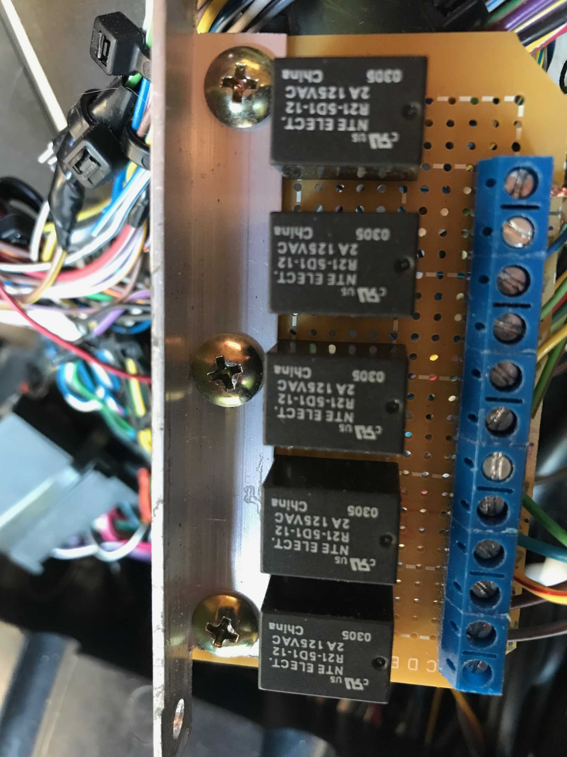
Now that the A/C is working I decided to tackle a minor issue with the Impala instrument cluster. The indicators for turn signals, lights on and high beams don't work. Those indicators are operated by data fron the Body Control Module. Swell, lets just hook them up. Uh, might need to read the shop manuals first and confirm how they operate. The Fiero harness brings the signals high (+12V) when active and low when off. Digging in the Impala documentation the BCM expects these signals to be driven low when active. Well that sucks. The simplest solution is to make a small relay PCB with inputs from the Fiero driving the relay coils, then use a normally open contact on each relay to connect to the BCM signals. I guess I could have used some kind of transistor or FET circuit to do this but relays are simple and isolate the Fireo from the Impala.
Here is the PCB, Hand wired. It lives in the center console next to the BCM. I built it with 5 relays in case I needed to add a fifth circuit
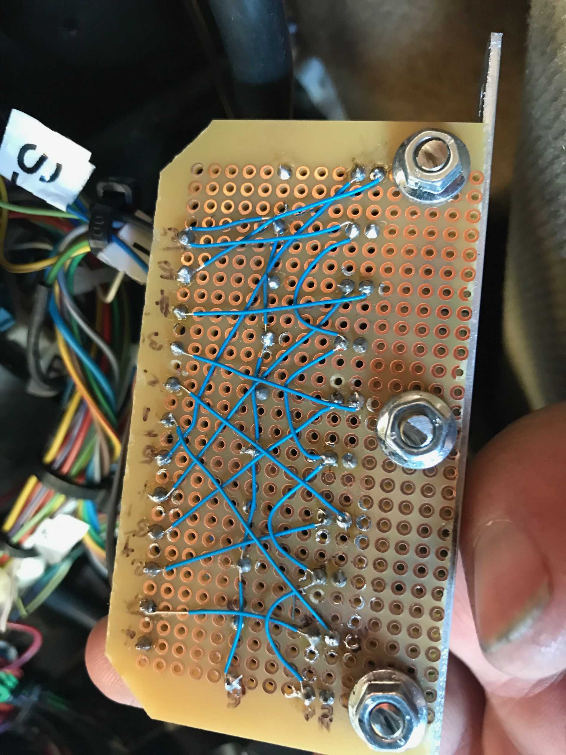
The back is #28 Kynar insulated wire I had laying around.
And it works! With some side effects though. Seems that the Impala BCU always turns on the daylight running lamps so the lights on indicator is always present. The high beam indicator does work eecept it will be off when the lights are first turned on. Once cycled High/Low it then works.
The turn signal indicators also work correctly without fail. But... Always a "but" it seems, the LCD display in the cluster sometimes says "Left (or Right) Turn Signal Lamp Failure". I'm guessing the BCM monitors the current to the Impala turn signal bulb, which does not exist. I might findt hose outputs and hook a resistor to each of them so the circuit can measure some current and not nag.
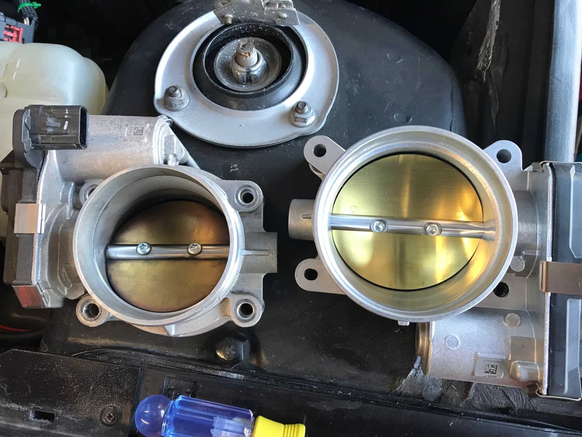
I took the car to a tuner recommended by one of my customers. Marty Stromberg has been tuning cars literally for decades in the Spokane area. I looked him up and found he has had several articles written about his work. Turns out he has a Camaro with the same LFX motor as I have So I had him do a first session of tuning to eliminate the anti-theft BS and do a first engine & transmission tune. While doing this he mentioned that the L89 throttle body was a bolt-on that increased the TB from 70 to 80mm. I dug around and found an adapter and the TB came from O'Reilly's.
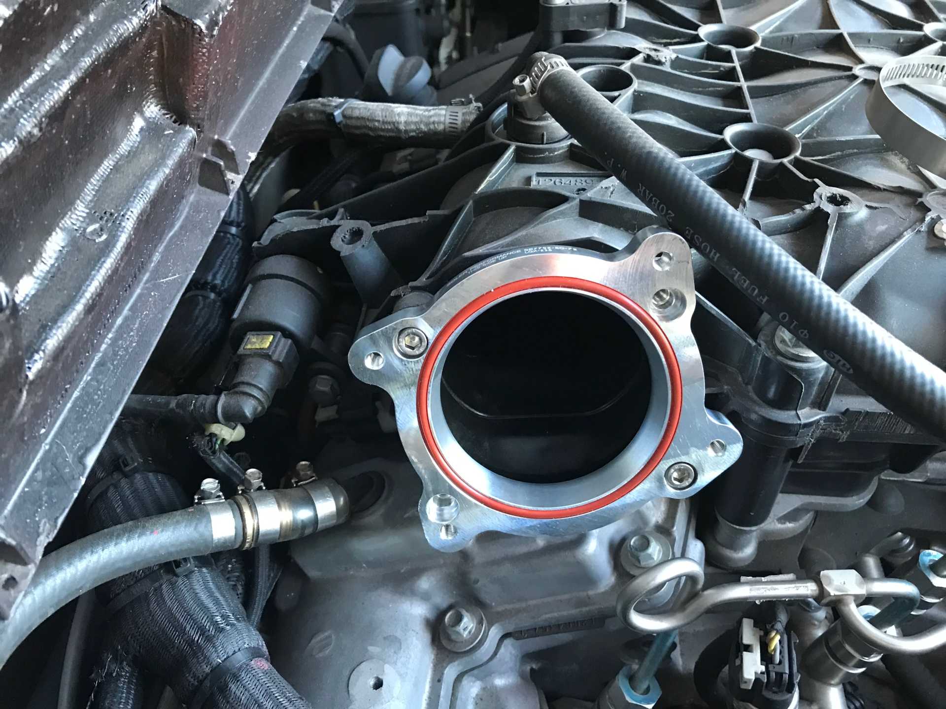
The adapter mounted to the intake manifold. I did some port matching on it to match the manifold inlet.
Here are the two TBs side by side. Bith have the same connector and wiring so no changes needed.
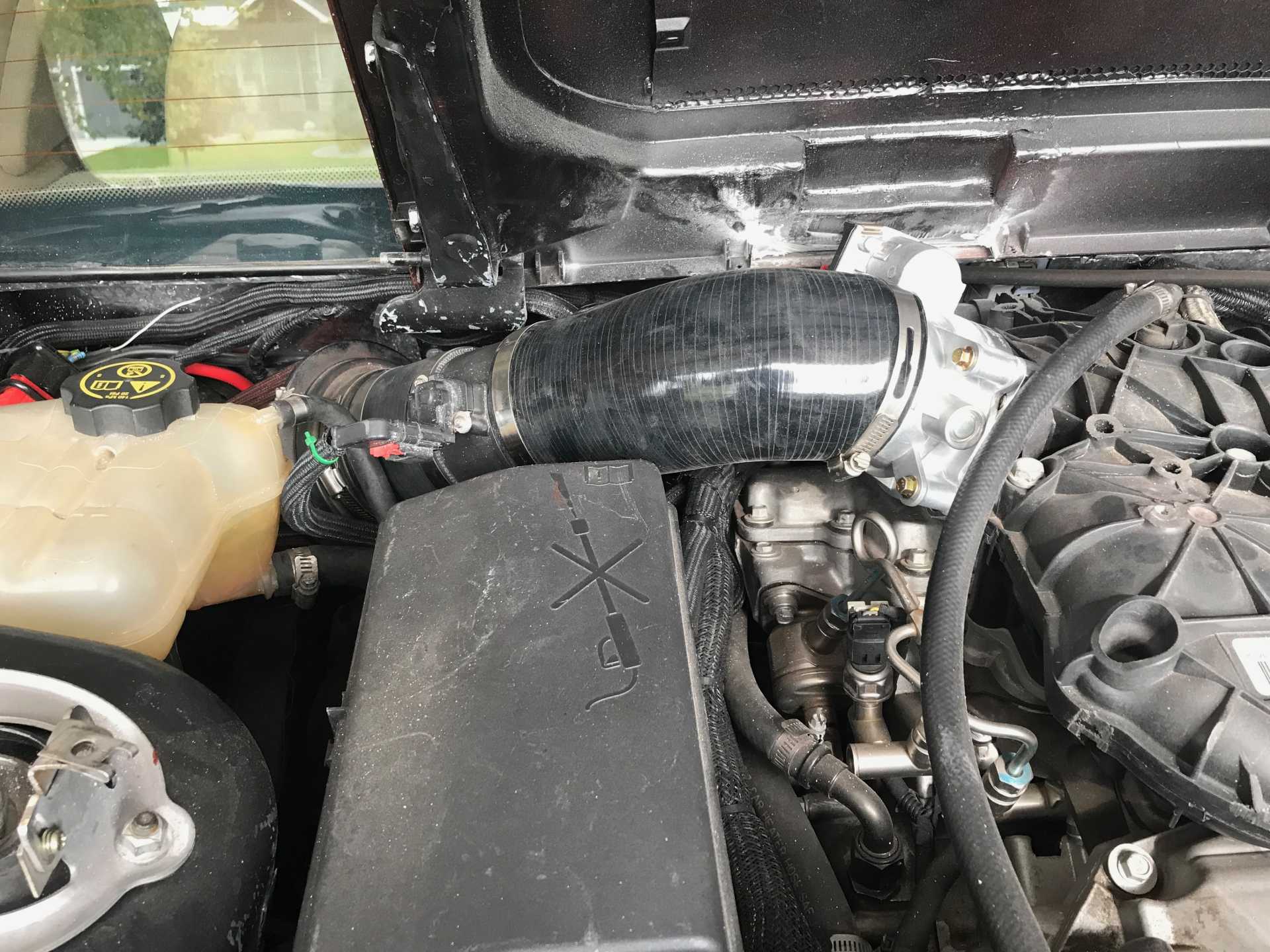
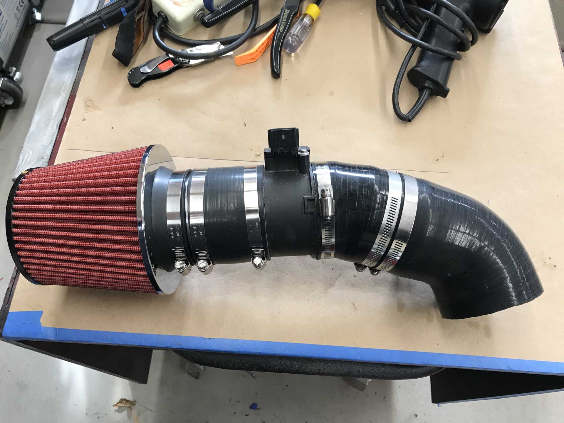
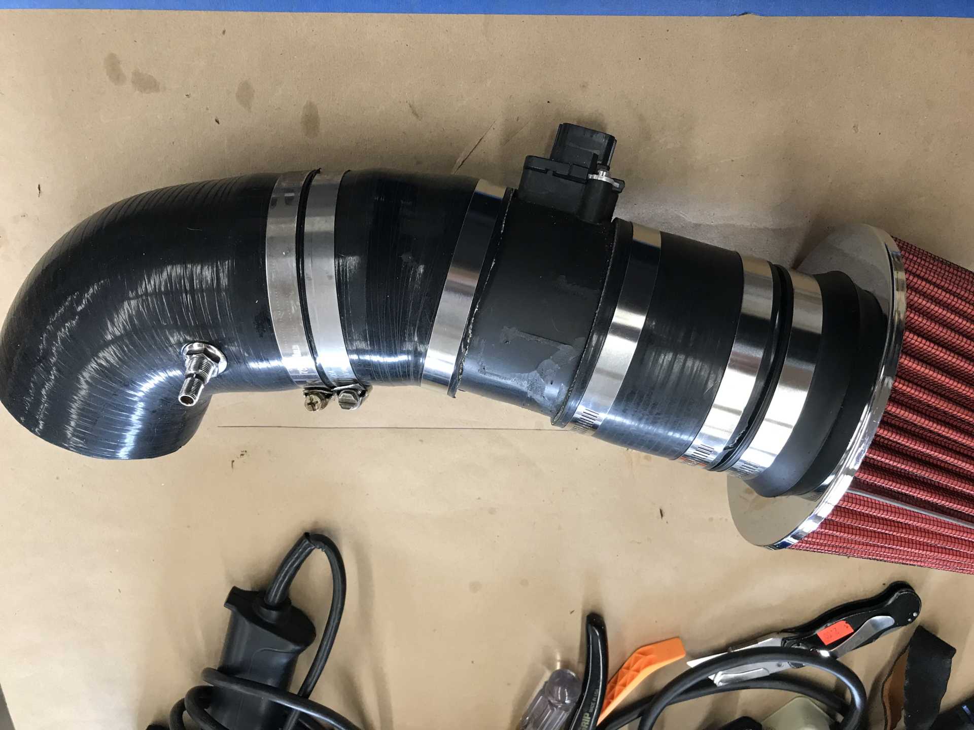
Then I rebuilt the intake to match the larger TB diameter with a tapered hose. I'll do more on it later on.
Naturally this made the engine not happy so I planned to re-visit Marty and I found the parts to make the intake 4" end to end.
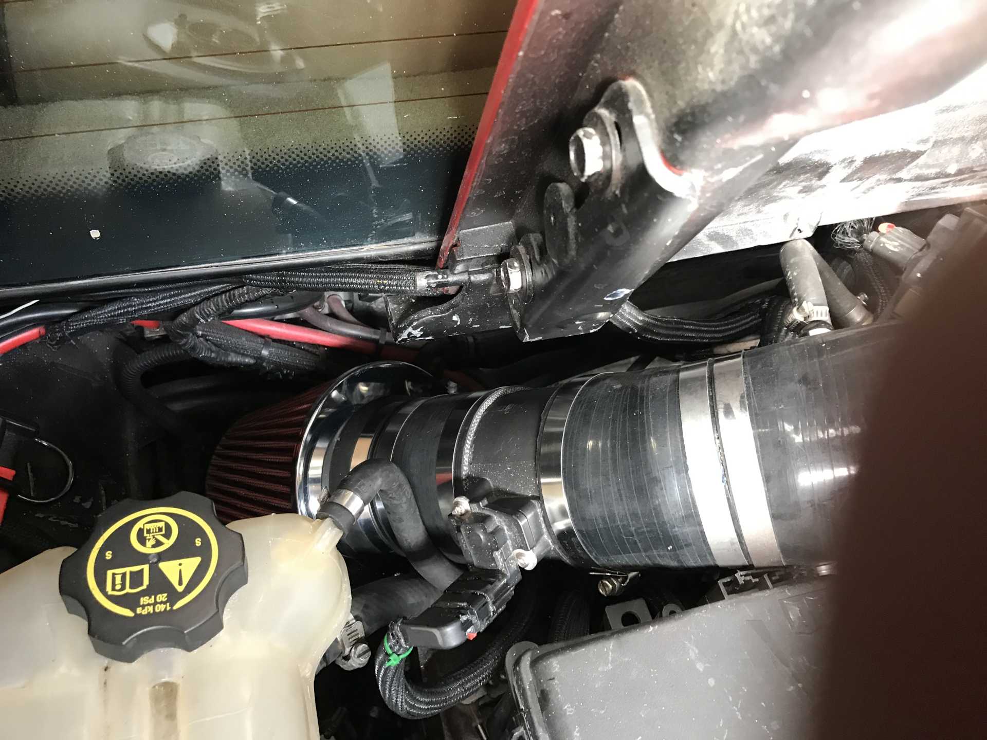
Back side view of intake
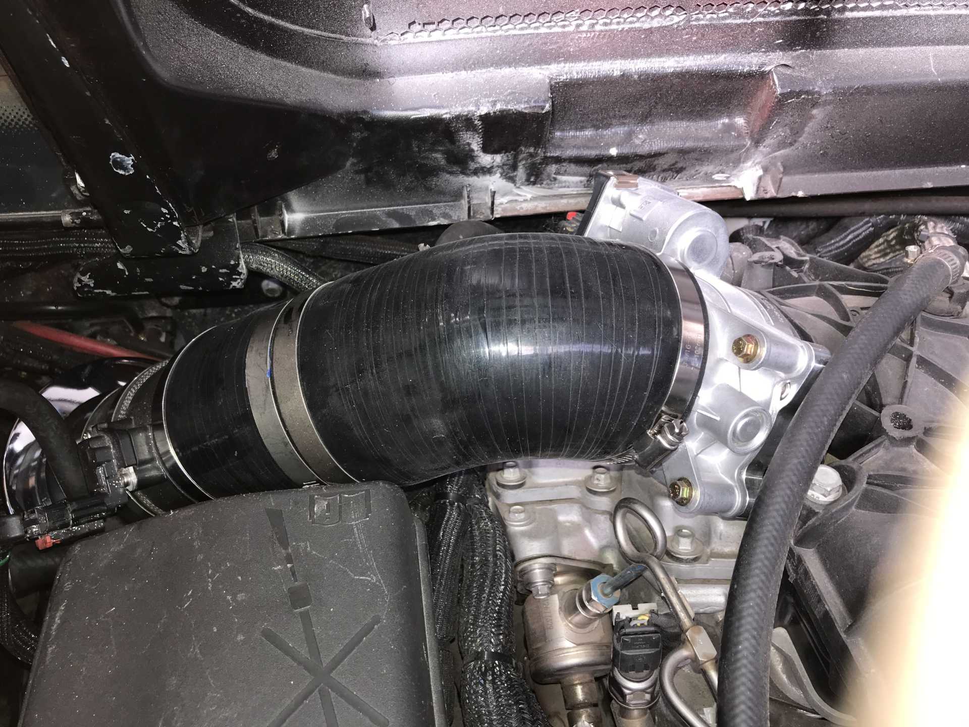
It's a bit tight here
But this end is good. Did need to increase the deck notch a bit to clear the TB connector
Putting the larger TB did not do too much for the performance and actually made normal driving much worse. Engine response when the transmission shifted was very laggy. I expected it would need a re-tune and scheduled another session with Marty. I asked him to focus on improving the engine performance and not worry about some shifting issues until the spring. He came through and made the performance improve under all conditions and improved shifting also. I did a quick quarter mile run and it looks like I'm now at 0-60 in 5.1, 1/4 in 13.8 at 104. I need to do more test runs but with the winter weather that will wait for the spring too.
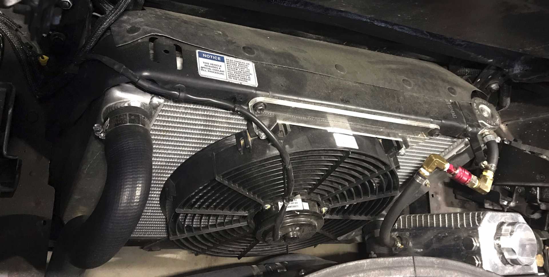
And then a problem appeared. I noticed some A/T fluid leaking at the radiator connection, seems like the fitting was cross-threaded when installed years ago. I looked into getting a replacement radiator with an internal A/T cooler and discovered most of them have plastic end caps, including the ones O'Reilly sells. Don't want that so I found a link to a guy who put in an all-aluminum Griffen radiator with minimal mods to the car. So the oil cooler would now be external. I sourced one and figured the best place to mount an external cooler was under the driver side cooling vent. This puts it directly above the transmission and in a place where upflow air will cool it.
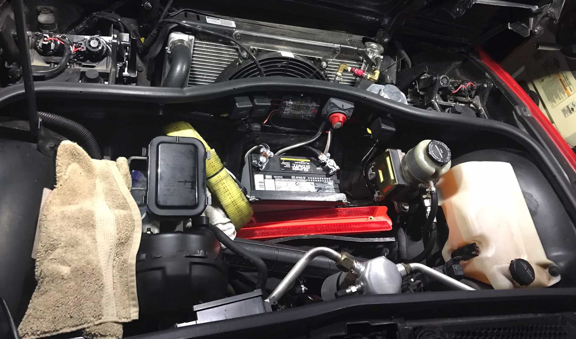
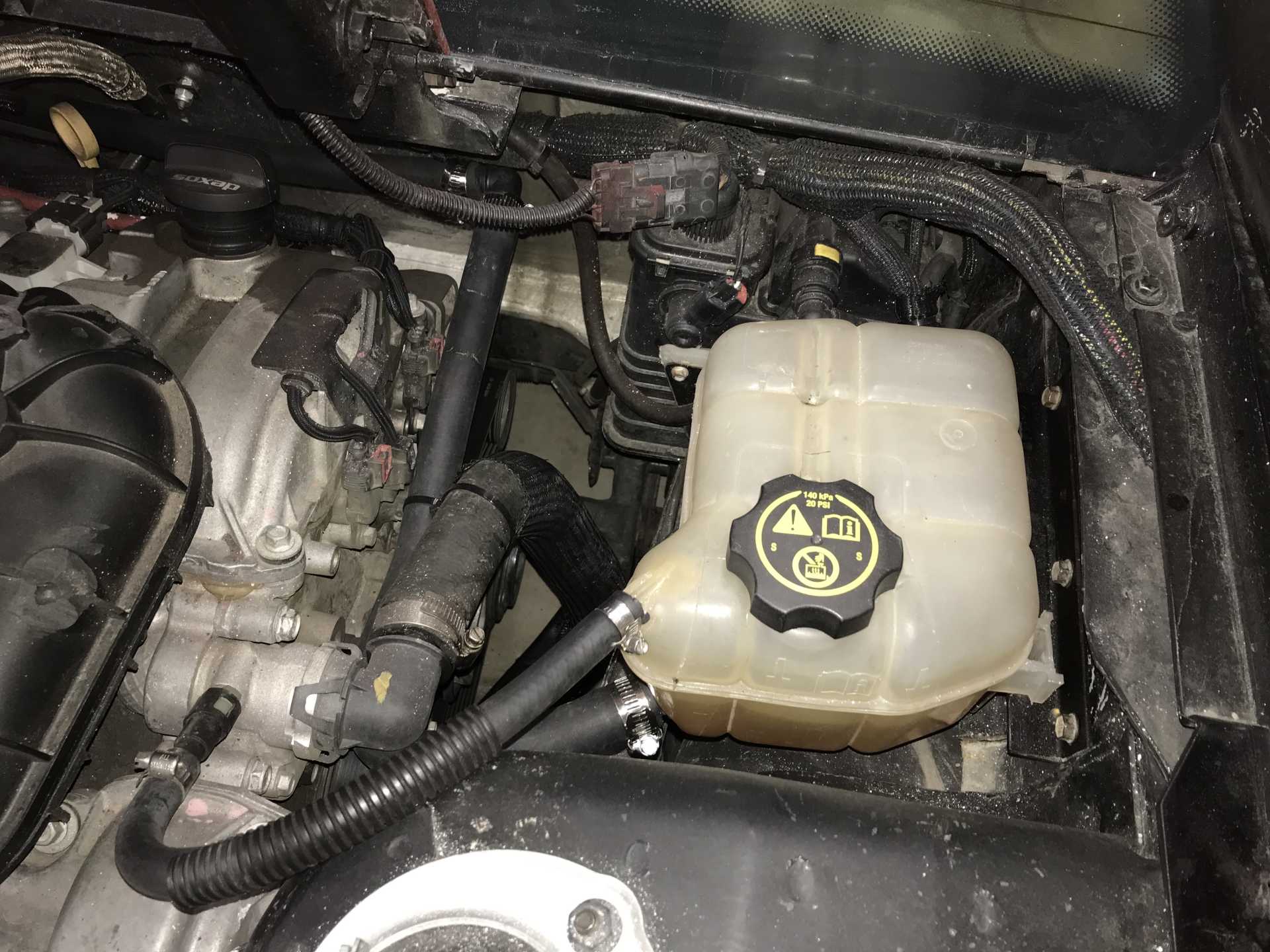
In order to put it there I needed to move the cooling overflow tank to the passenger side, this had several positive effects. The driver side now has room to fit the new A/T cooler; has more room to accommidate the engine air intake; makes working on that area much simpler with more room to access parts and removes a visible cooling hose from the rear of the engine. The passenger side had a big unused space where the coolant tank fit nicely. At the same time I noticed coolant was escaping to the front coolant overflow tank when I lifted the rear end of the car to crawl under. This drained coolant into the front overflow tank and lowered the coolant level in the engine and Impala overlow tank. I decided to seal the front radiator cap and then remove the Fiero overflow tank. After all the Impala had only the one overflow tank with a direct hose from the engine high point to burp air out of the system. I cut a piece of 1/8" hard rubber sheet to fit in the radiator neck and block the radiator cap. By adding it the pressure needed to release the radiator cap was higher than the pressure to release the Impala cap in the back. I then removed the Fiero overflow tank. Problem solved at no cost.
Location of the new A/T cooler
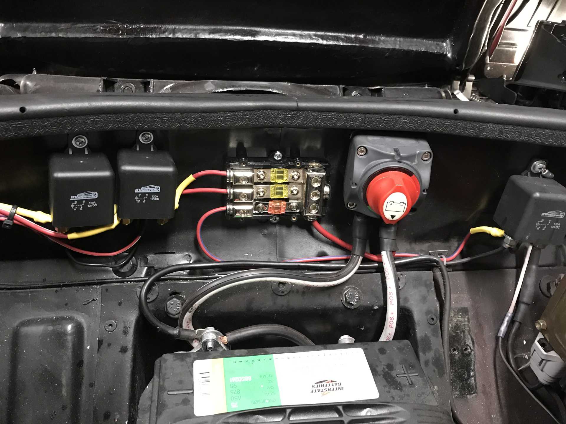
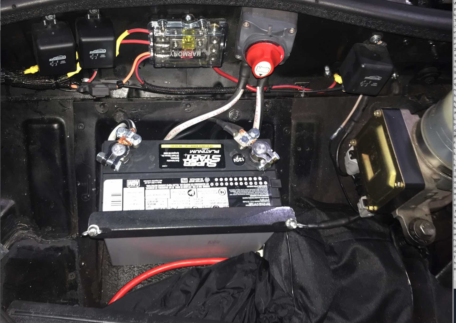
Hoses connecting to the transmission are just below it. Red connector on the left is for my jump-start cables, Getting to the side-post battery in front is difficult. My jumper cables have a mating connector on one end and normal clamp connectors on the other. If you want real copper jumper cables expect to spend at least $80 or more.
This hose is now deleted
So it looks like this now
And the tank is now on the right side, The missing hose now runs ahead of the motor.
I also found a source of some vibration while crawling under the car. There was a exhaust clamp bolt touching the edge of the trunk. Cut it off with an angle grinder and the vibration is lower than before.
In order to put it there I needed to move the cooling overflow tank to the passenger side, this had several positive effects. The driver side now has room to fit the new A/T cooler; has more room to accommidate the engine air intake; makes working on that area much simpler with more room to access parts and removes a visible cooling hose from the rear of the engine. The passenger side had a big unused space where the coolant tank fit nicely. At the same time I noticed coolant was escaping to the front coolant overflow tank when I lifted the rear end of the car to crawl under. This drained coolant into the front overflow tank and lowered the coolant level in the engine and Impala overlow tank. I decided to seal the front radiator cap and then remove the Fiero overflow tank. After all the Impala had only the one overflow tank with a direct hose from the engine high point to burp air out of the system. I cut a piece of 1/8" hard rubber sheet to fit in the radiator neck and block the radiator cap. By adding it the pressure needed to release the radiator cap was higher than the pressure to release the Impala cap in the back. I then removed the Fiero overflow tank. Problem solved at no cost.
Great that you're making progress on the car!
I'm not sure your cooling system mod will work out well. I've been able to get a Northstar to purge air by having a lower pressure cap at the back with a higher pressure cap at the front, while keeping the Fiero overflow tank at the front. Note that this purges air from one end, then refills coolant from the OPPOSITE end, keeping both ends topped up.
The Fiero system has TWO high points, while the Impala system only has one. That's a big difference.
If you run a LOWER pressure cap up front, then the system will purge air out the front cap. With the nipple capped off, it will not be able to pull in air from the front. You will see the level in the surge tank in the engine bay drop as the system purges air from the front. Then you just top up the surge tank.
[This message has been edited by Will (edited 01-28-2024).]
Originally posted by MikesFirstFiero: Naturally this made the engine not happy so I planned to re-visit Marty and I found the parts to make the intake 4" end to end.
As now configured the high point of the entire system is the Impala tank. The last photo shows the curved hose from the engine high point going into the tank at it's top (burp hose?). The feed from the tank to the engine is the hose from the tank bottom running forward to the firewall and then to the driver's side where it hooks up to the thermostat housing in the driver's side (picture in a earlier post). The radiator isn't near as high as the engine compartment tank. The front radiator cap was rated at 16PSI and the rear is 20PSI but the front now has the seal of rubber that blocks the suction operation ans would open only if the pressure exceeds more than 16 PSI. I'm not really sure what that pressure is since I haven't measured it yet. The Impala had only the one tank I used with a different philosophy from the overflow tanks of the past. I had been losing a slight amount of coolant but traced that to two hose clamps that were not very tight under the car. I'm keeping my eye on it to see if it works as needed.
In practical terms the old 2.8 was always difficult to keep cool. The Impala runs much cooler and has never shown any signs of overheating in 7,000 miles. I've disabled the radiator fan for the winter and won't need it until air conditioning season. That was a real surprise. Maybe since the LFX is more efficient and rejects less heat to the cooling system than the old engine did in normal city & highway driving.
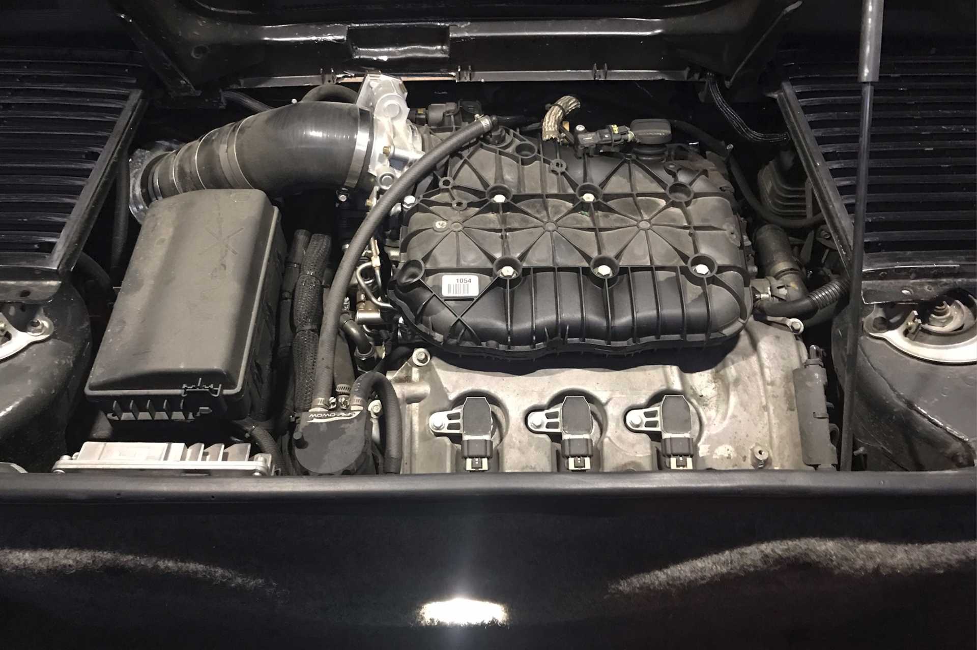
The MAF is the original Impala unit. I only shaved the OD of the housing to match the hoses on both ends. It keep things simple and reduce costs I've tried to use as much of the original Impala equipment as possible. And the valve stem on the hose is drilled out and provides metered air to the forward valve cover.
[This message has been edited by MikesFirstFiero (edited 01-29-2024).]
You have two high points in your system. The radiator is a high point. Air under the radiator cap when you install the cap has no way out. Air that later arrives in the radiator has no way out.
You could deal with this by running a hose from the overflow nipple all the way back to the tank in the engine bay. It's easier (and safer due to the potential for damage to that small hose) to swap to a lower pressure cap on the radiator.
I was in Spokane on a work trip, and saw the Fiero's sitting out there. I walked over in my pilot uniform while waiting for a ride to the airport! Some sweet cars.
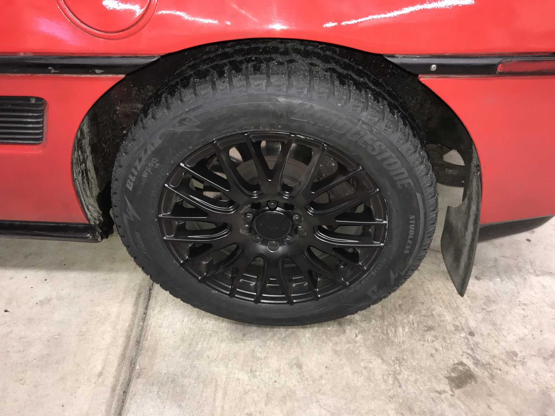
With that set of problems resolved for now It was getting into the beginning of snow season around here. Usually we get most of our snow in December with the first storm around Thanksgiving. I decided to call a halt to improvements and prepare the car for winter. The 16" wheels are swapped for a set of OEM 14" which means the brake calipers need their spacers removed and a set of OEM rotors installed. This would be the fourth year I did the swap. The problem was that when I tried to remove the spacer bolts (Flat head Allen Sockets) the bolt wouldn't budge and began to deform the socket. That meant new 16" winter wheels and tires since I need the car four days a week. I looked around and TireRack offered the best deal. A set of 205/55-16 Blizzak WS90s on wheels very similar to the summer ones including mounting, balancing and shipping for $1225 plus local tax.
Winter tires, Blizzaks work great for studless tires.
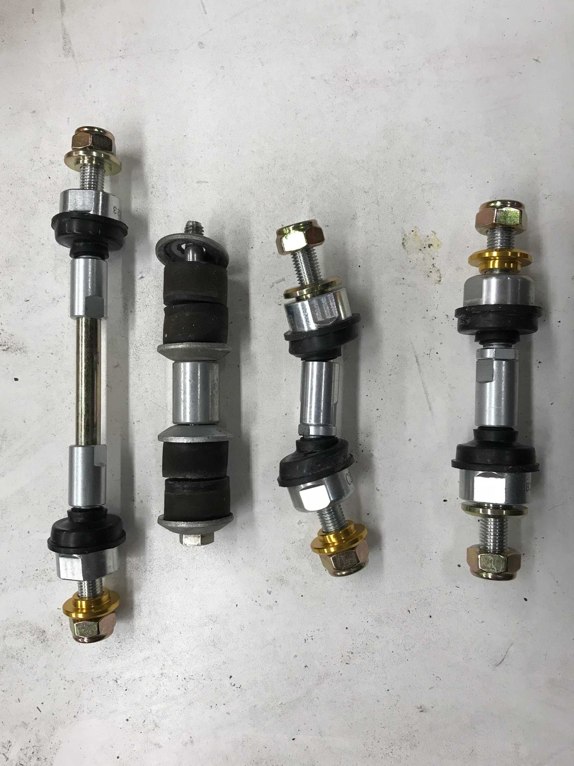
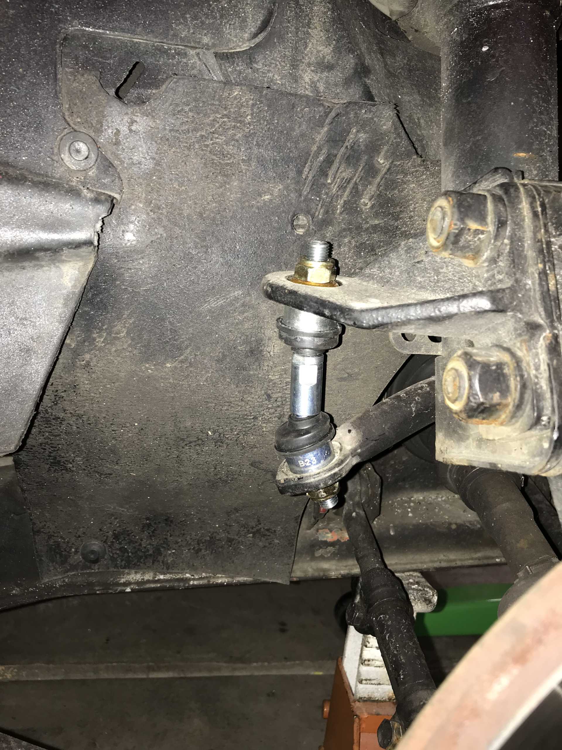
While waiting for them to arrive I had ordered a set of Rodney Dickmans ball-joint sway bar ends and got them mounted. No problems at all. I'll be sorry to see Rodney close up his shop.
They popped in easily, I've never liked the bushing mount design since it's not aligned unless you are at the static height and the poly bushings break apart rather than just turn to mush like rubber ones do.. Yes that is coolant. I discovered a loose hose clamp and fixed it. Guess that's why engine compartments aren't painted green.
Then I noticed a small brake fluid leak from a rear caliper. Time to fix those with some spare seal kits. I'll JUST rebuid them again. But it gets worse due to my lack of reading the shop manual completely. The calipers were leaking from the inner seal in the piston. For other newbies the rear caliper has a normal caliper seal just like the fronts do. But the piston also has an inner piston and seal that is part of the E-brake, that was leaking. Dug into the shop manual and yup, there it was. And it may be irreplaceable. Problem is that rebuilt 88 rear calipers are very scarce I doubt they fix the inner seal. I've not seen an inner piston seal in any of the rear repair kits I bought. I think that the inner piston seal is never replaced for "rebuilt" calipers like from Cardone and others. I tried finding rear calipers from RockAuto and O'Reilly's (who buy them from Cardone it turns out), nothing.
I then bought a pair of 48mm pistons said to fit the front calipers to try in the rear. They turned out to be 0.1mm (.004") too big. Ok, how about using complete front calipers? I found one on the O'Reilly system and ordered it, that was a flop too. The caliper would work except it requires new brake hoses since the rear hoses are built to avoid the E-brake lever and are not long enough to fit the front caliper. I'll hang on to it just in case,
And the Cardone unit I purchased showed they know nothing about the rebuilding of a Fiero caliper properly. The sliding pin dust covers were not installed under the pins on the caliper end and were simply loose. Even worse the calipers were nicely painted - even on the slider bores. One pin was glued in place by the paint. If you buy any of this crap then expect to disassemble it and check out everything and fix their problems before you can use it. One thing I found that did work is the Centric repair kits do fit the calipers and work OK. My fronts have seals 4 years old now with no problems. The seals removed from the rears were still good too but I replaced them since I was already in there.
Paint on the slider pin bores. Top is painted from rebuilder, bottom I cleaned.
In the end I opened up the old rear pistons and removed the inner piston and it's retainer, cleaned it and welded the vent hole shut. Put it back in with new sealsbled the system and it now works better than ever before. Previously the brakes never had a really stiff engagement, now they are acceptable. I'm guessing the inners have been seeping for a long time. I don't have an E-brake on the car and rely on the transmission lock. It's not as good as a real E-brake but it keeps the car stationary when stopped like any other automatic. It looks like there will be a shortage of properly rebuilt rear 88 calipers in the future. I've got seal kits and a pair of unlooked-at old rear spares just in case the current ones fail. MaybeI'll look into Wilwood or something else in a fixed caliper.
All this stuff lives inside the rear piston. You can see the old inner seal is bad.
I did decide to deal with another problem of driving in winter - lighting. I'll pick up there next.
[This message has been edited by MikesFirstFiero (edited 01-31-2024).]
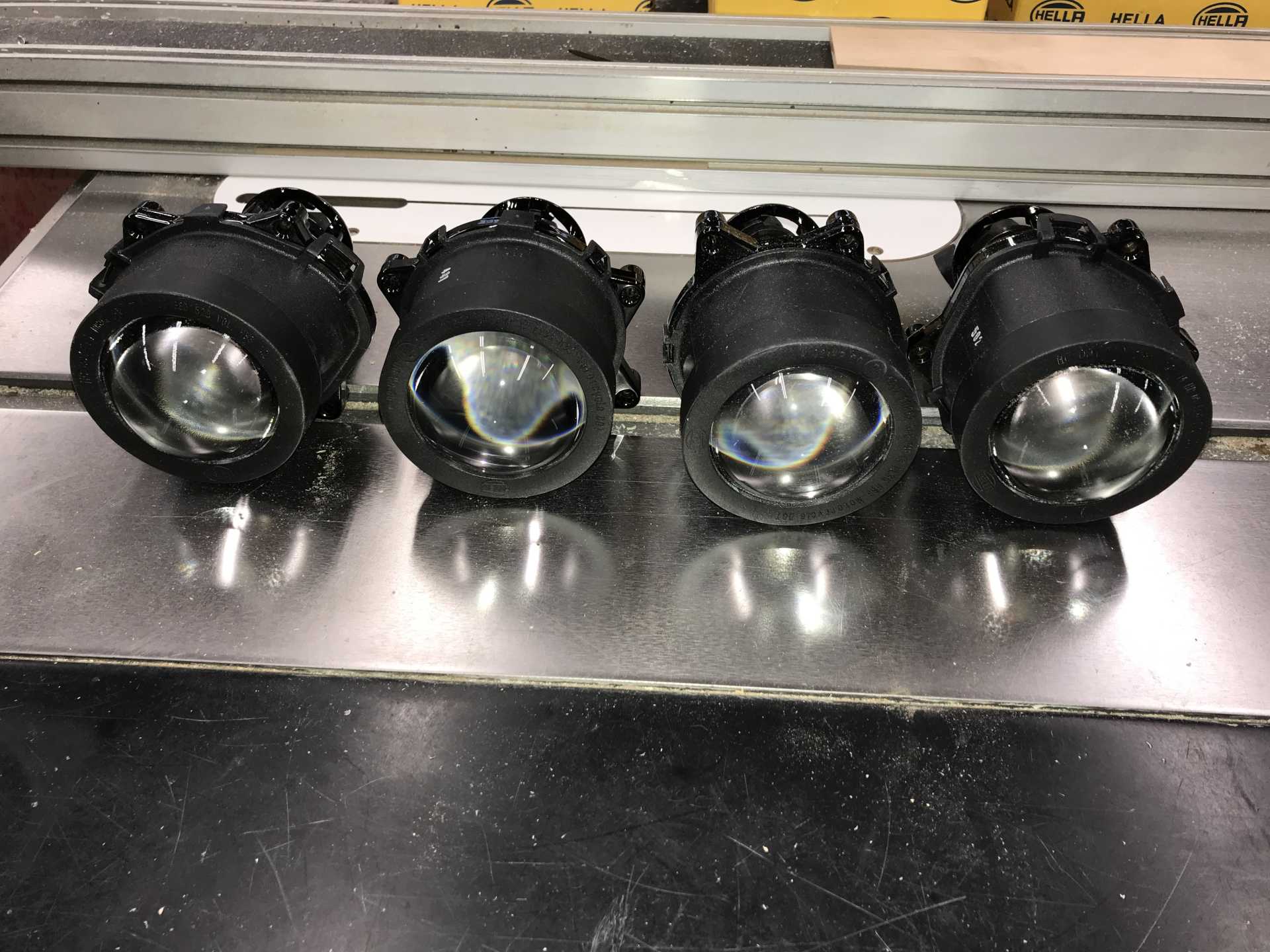
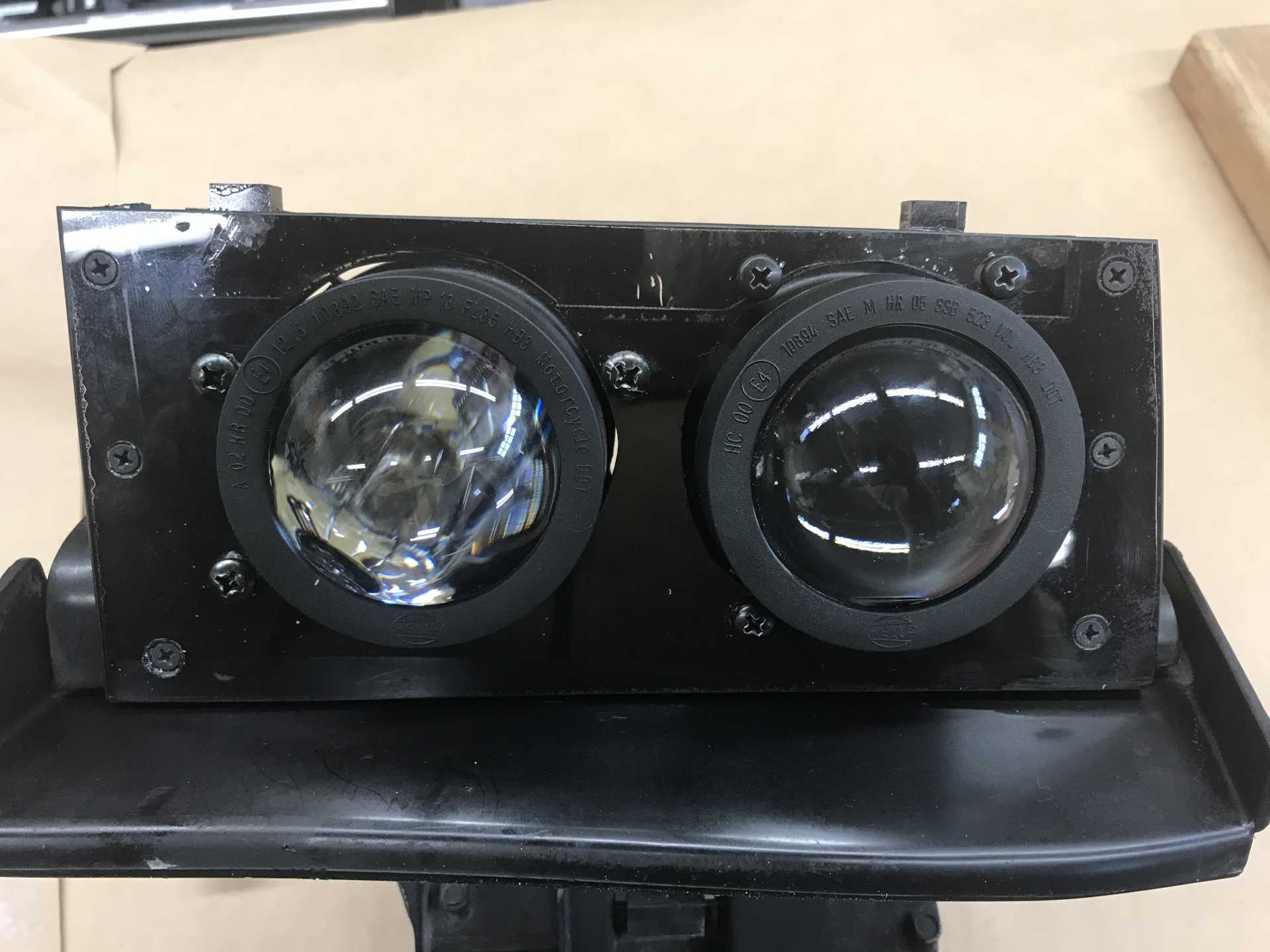
Around here it gets dark at 4PM at the second half of December and it can be cold too. This year our low has been -20F overnight for a few nights. I've got a good heater and the LFX warms up very quickly so the car isn't cold for too long. But the lighting with OEM 5 x 7 lamps is simply crap. I've seen several posts here on other solutions and some of them look appealing but costly. Then I found a sale on Amazon for Hella 90mm projectors. Low beams $35 and high beams $30 including 9005 bulbs. Deal.
$130 worth of lamp holders.
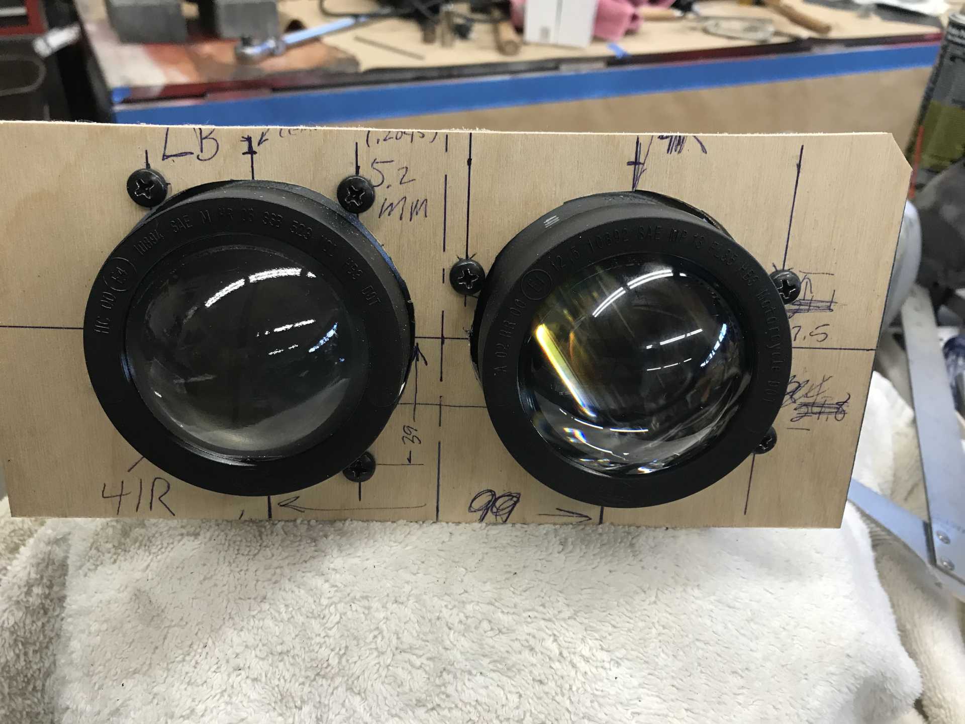
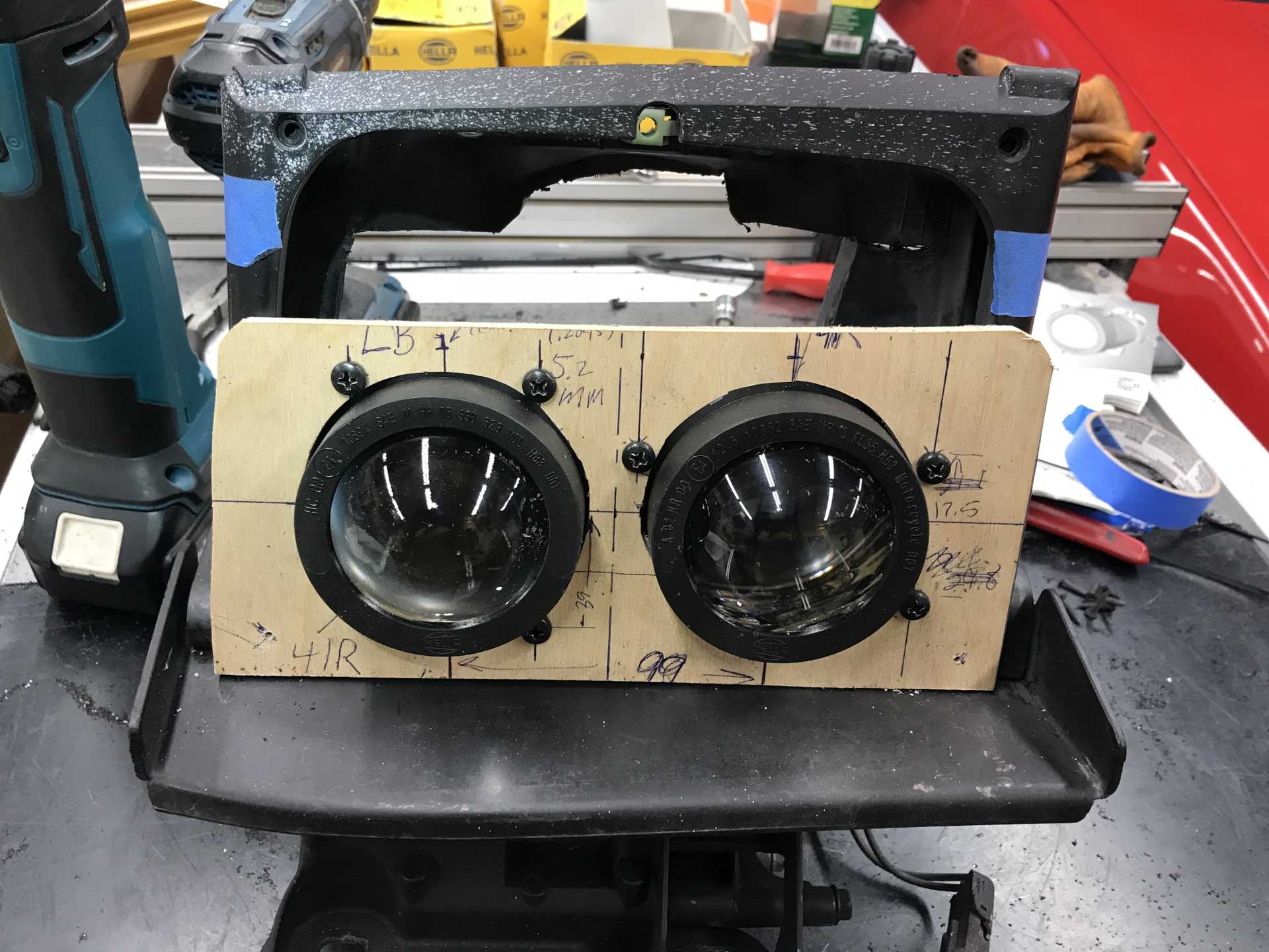
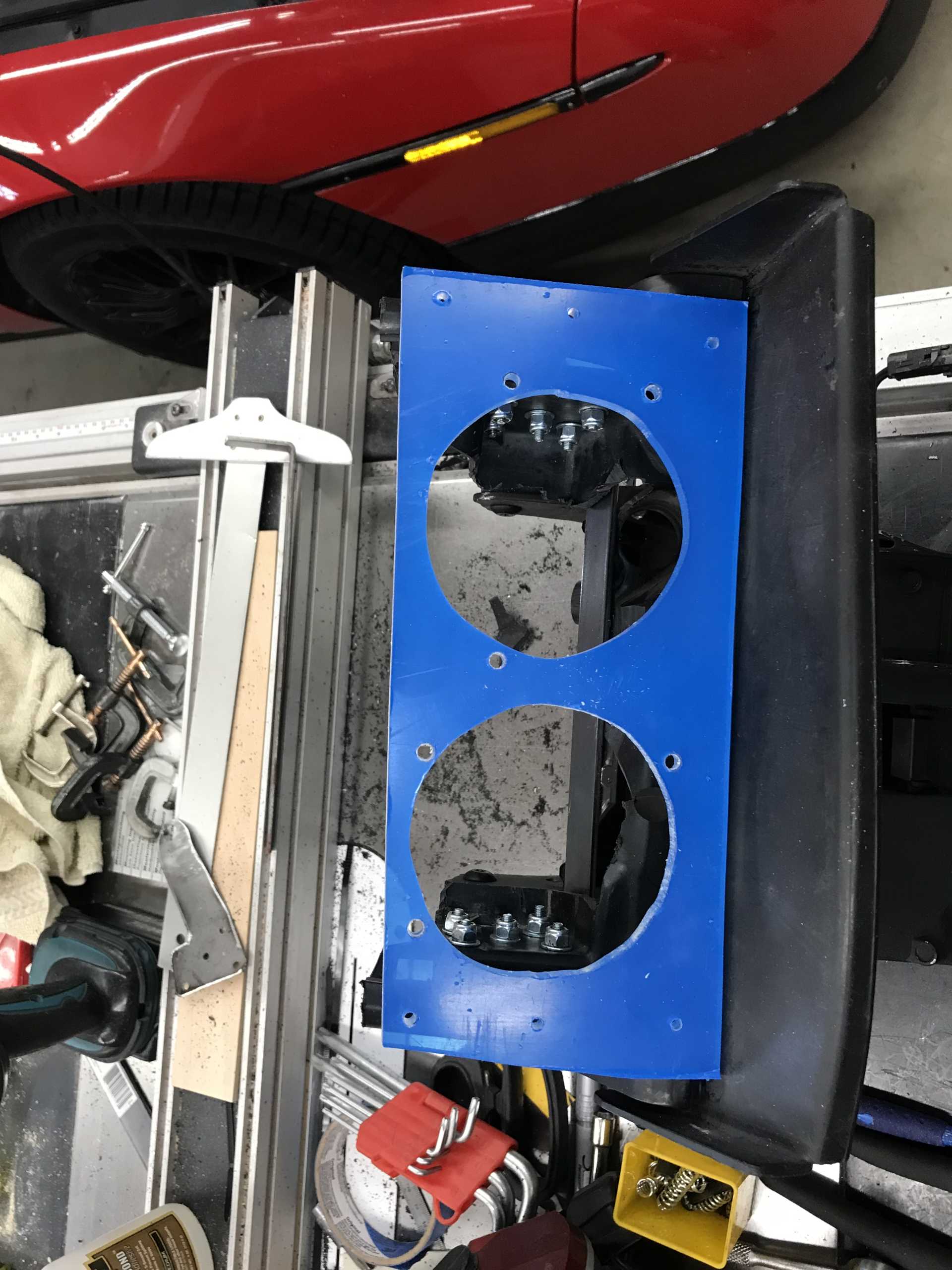
They sat around for a while until I needed them. I mean, how difficult can putting these Hellas in the original fixtures be with some mods. Answer: More difficult than I ever imagined. I did some basic measurements to see how tall the lamp mounting plate would need to be and how close they would need to be to each other. More answers: About 3/4" higher than the Hella mounting hole diameter (82mm) and as close together as possible. The height was not an issue but the width would prove to be important since the new lamp housings are much wider in the back than the originals and will take a lot of room.
Mounting template made from 1/4" plywood
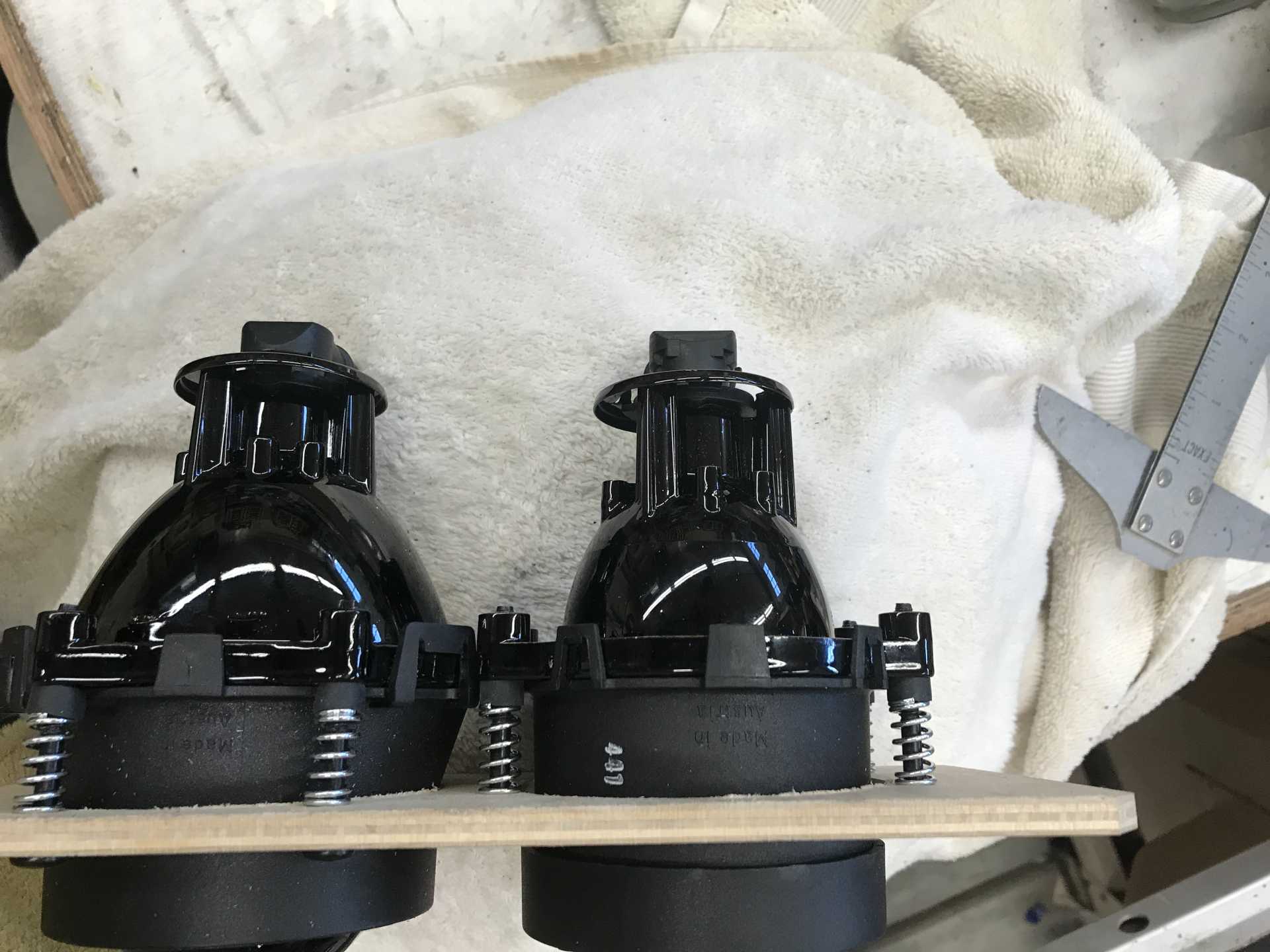
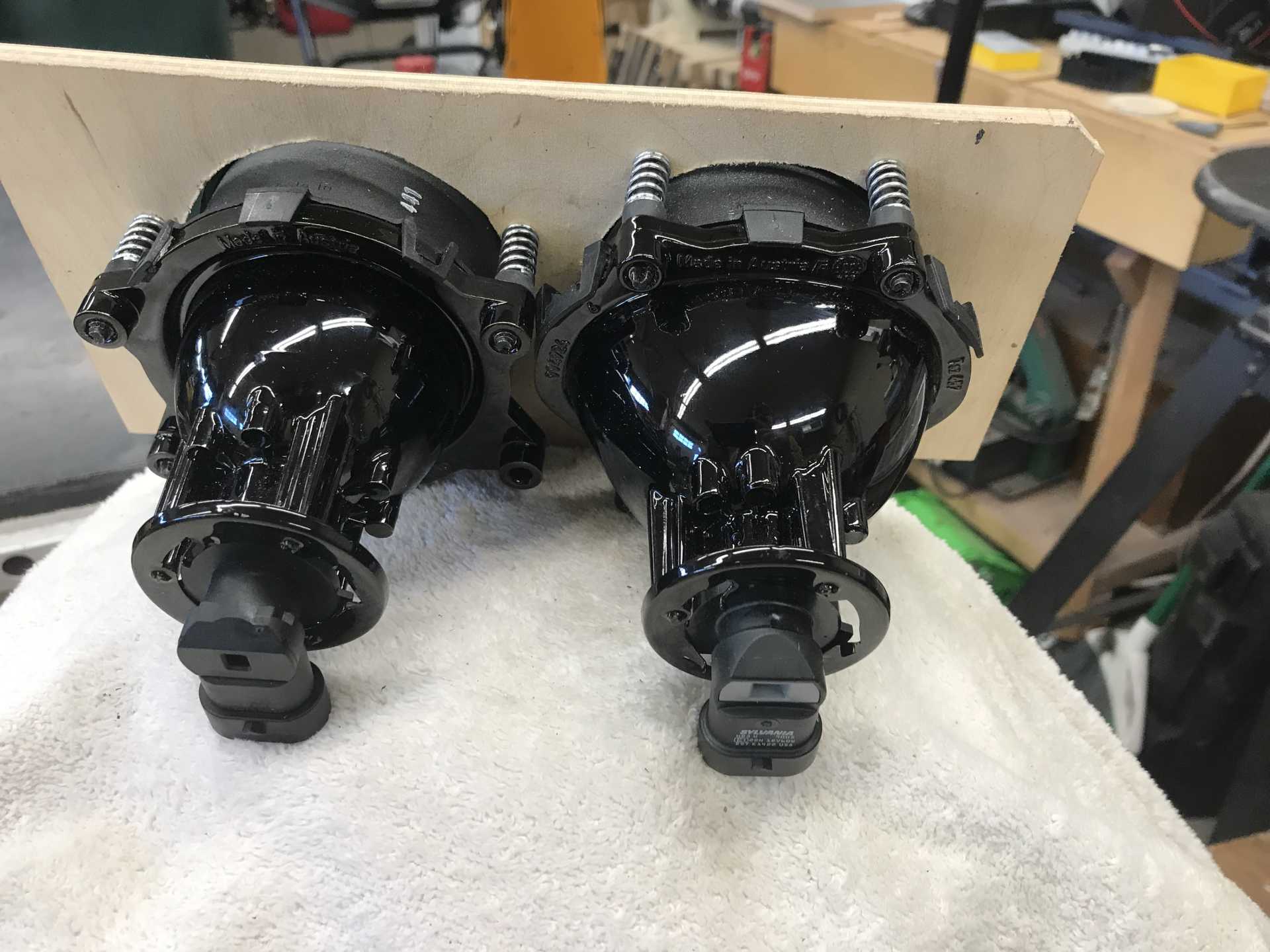
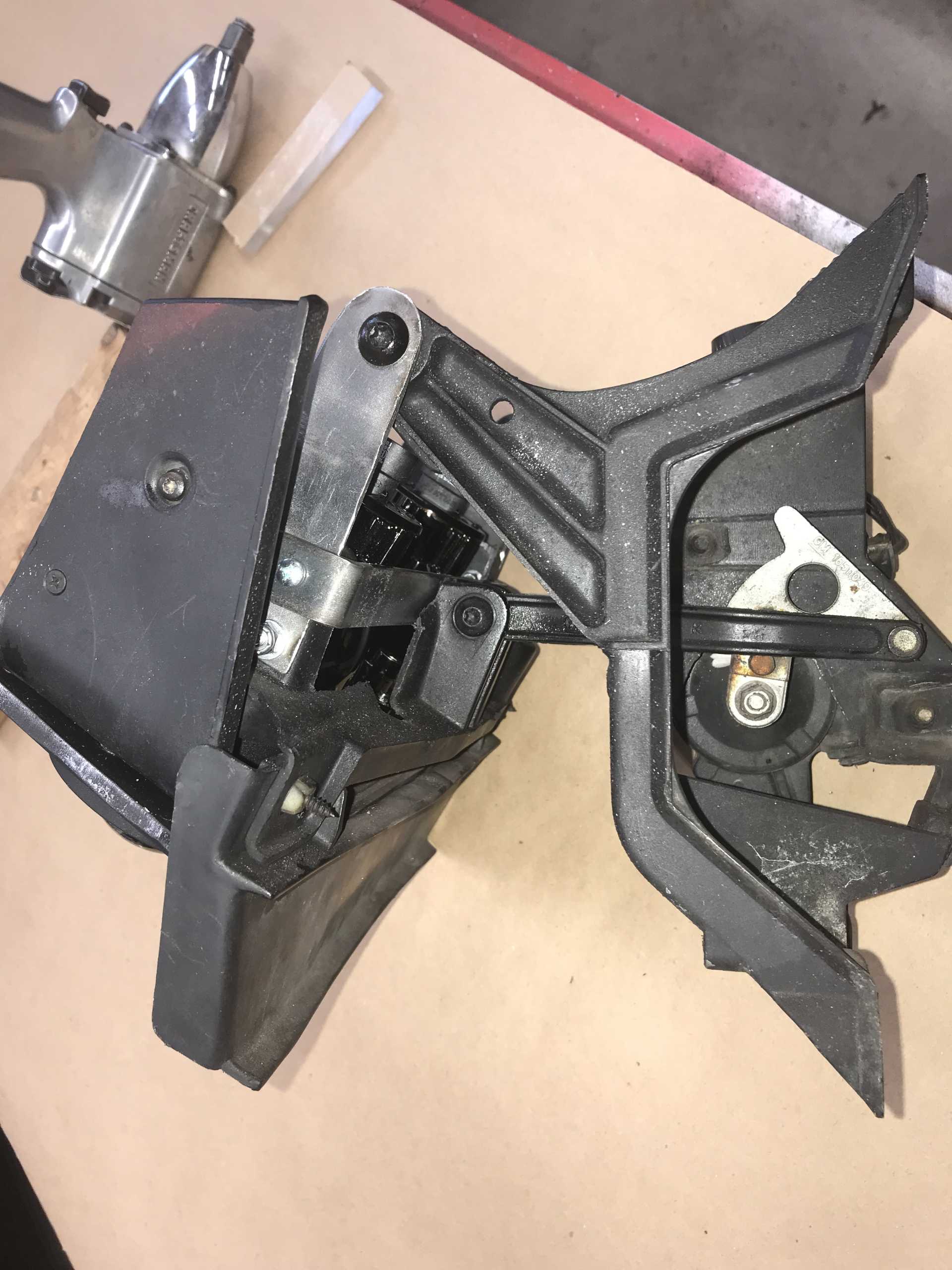
View from the top. These are very wide and mean most of the plastic needs to go away.
And from the rear. Those 9005 right angle lamps would become a problem really quickly.
It's going to be a lot shorter than before, even shorter than this photo. This is good since I hate the bug-eyes sticking up. Now the lids are barely visible over the hood
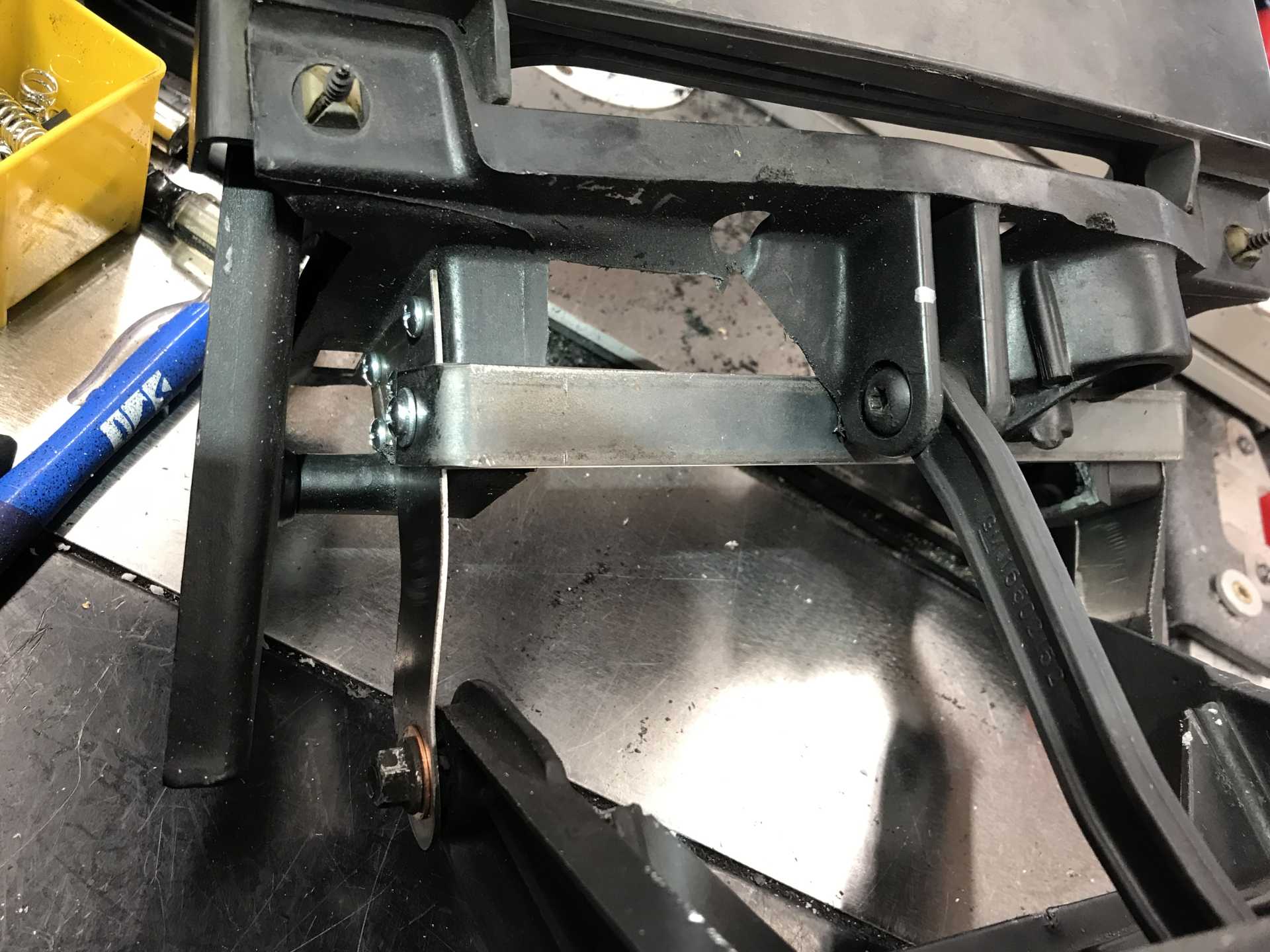
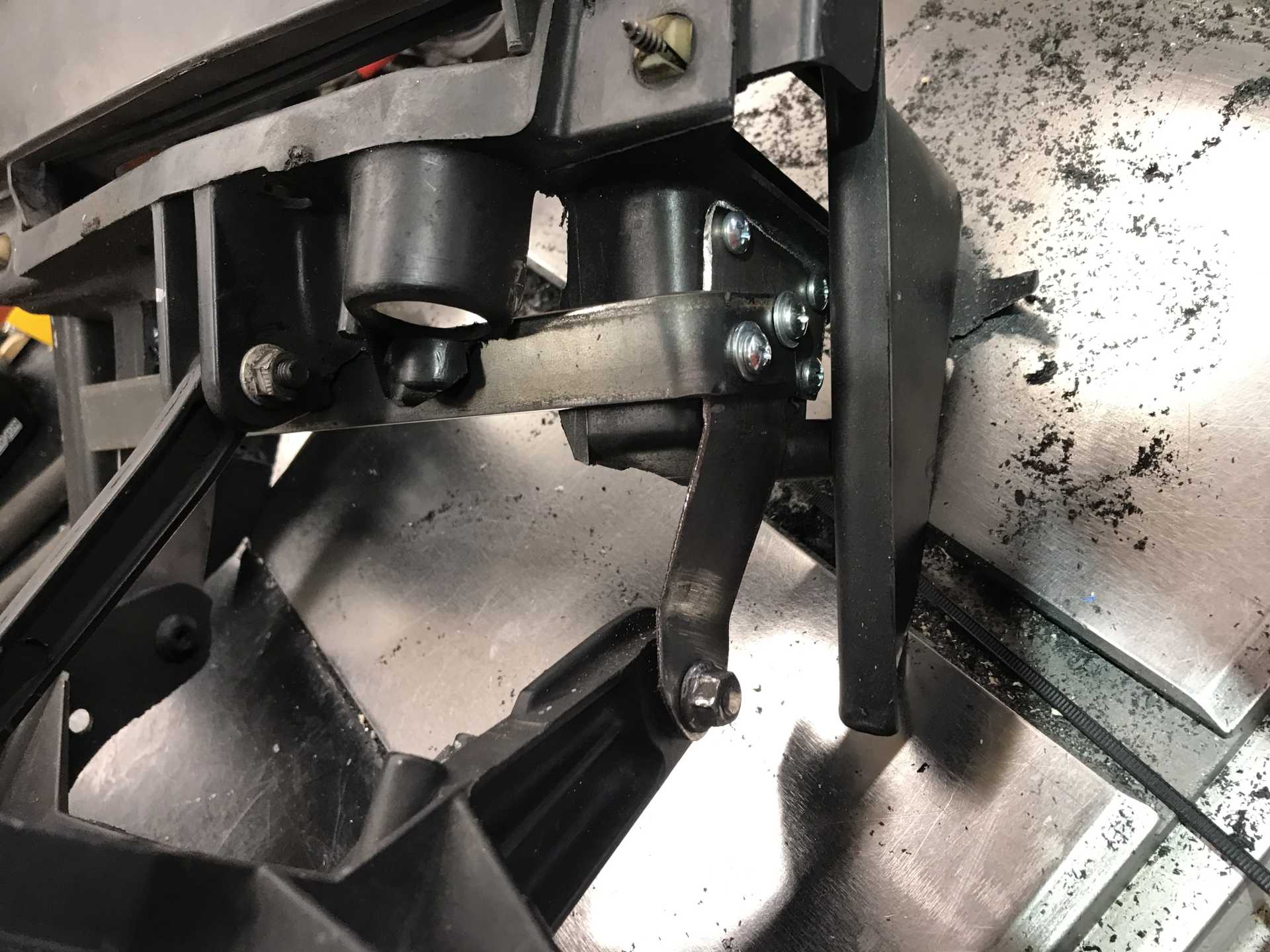
I popped off one assembly, stripped out all the old lamp parts and began cutting the plastic with a Makita vibrating tool. And the hole got bigger. And bigger. Until the structural integrity was mostly gone. It looked like a metal lower support would work, leaving the pushrod attachment in original plastic (it pressed on the metal bar I added (1/8 x 3/4"). to lift the lights The side panels and hinge point were replaced with sheet metal since the remaining plastic was not stiff enough after cutting them for lamp clearance. These metal side pieces were the mount for the added lower support bar. Lots of screws for rigidity were used, probable could have been fewer. Put the assembly back in the car and it sorta worked. The lamp cover squashed the whole thing down too far and flexed the metal support. No Go.
The initial support bar. Sounded like a good idea... but not rigid enough
While the hinged side plates worked well, the support bar was inadequate. The lids do press down with a significant force so the new structure needs to be really stiff.
The problem is that the bar deforms too much and the plastic pushrod end moves too since it is not tied to the support bar.
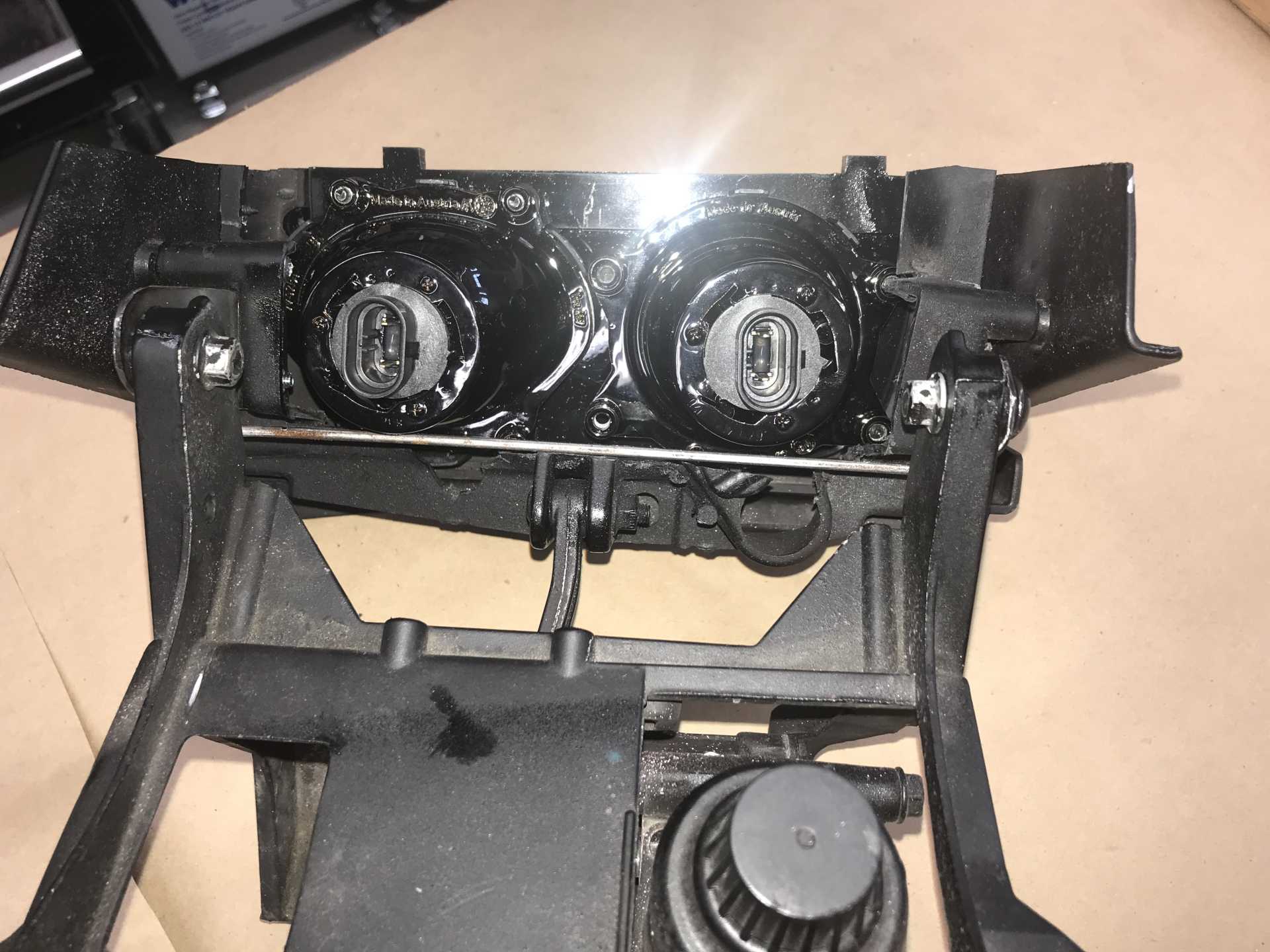
Now the problem with 9005 lamps is clear. The right angle 9005 connector interferes with the support bar. There is a solution as you can see, I used the 9005XS lamp with a straight connector same lamp with a straight conector. End of problem. Also the high and low beam lamps are all 9005s. Normal US lamps require a different lamp with a forward shield for low beams. This Hella lamp uses a built-in metal shield to block the upward-direction light and not blind on-comers, no need for a different bulb. But as for driving the Fiero almost half of our cars locally are massive pickups and their lights are so high they might as well all be high beams.
Time to cut the real mounting plate from 1/4" polycarbonate. It was cut to the template height and later dropped by 1/4" as the extra height was not needed.
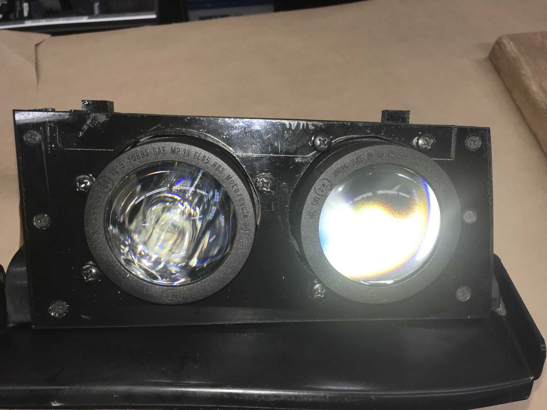
Acrylic panel painted black on the back side, with a doubler on the back for stiffness and to have points of contact with the lid. Euro-style sharp cutoff low beams. High beam lamp shows internal reflections of lamp.
Two more mods were needed, the support bar had a flange added for stiffness to cure the bending and the plastic push rod mount was replaced with a metal one welded to the support bar. That finally worked and stiffened up the entire structure.
Finally as it is now after all the tweeking.
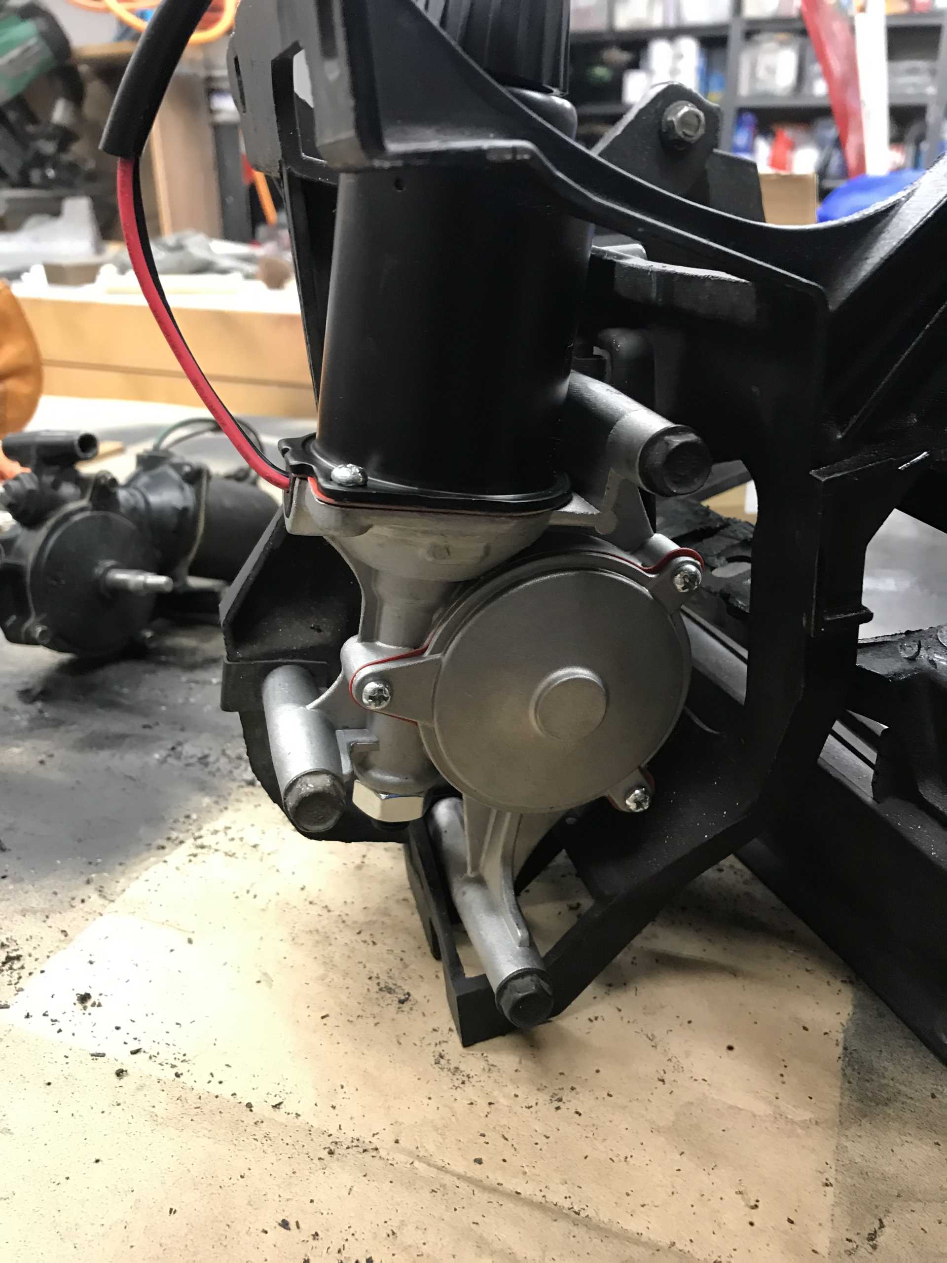
One more addition, new motor assemblies. Now available on Amazon for about $75 each. Exact fit, works as expected, no issues. One of mine began not lifting in the cold weather and I was going to rebuild them until I found these.
After the first Assembly was sorted out the second one took just a day to complete. Mounting in the car is a bit fussy to get the assemblies in the right spot for smooth operation. Marking the positions before removal is a good idea.
Wiring was done from the front-mounted battery through separate fuses for high and low then to separate relays in the front compartment and finally to the lamp connectors. The lamp switch operates only the coils of the two relays and carries less than an Ampere. The relay power circuits are all #12 wire to insure the lamps have the full system voltage available. Getting the lows to come on with the highs meant adding three diodes going to the relay coils. Two for circuit isolation and 1 to feed the low beam relay when the highs are on. The isolation was to keep the Impala BCM from becoming confused about why low beam power is present when the high beams are on. Not really sure it was needed but won't hurt.
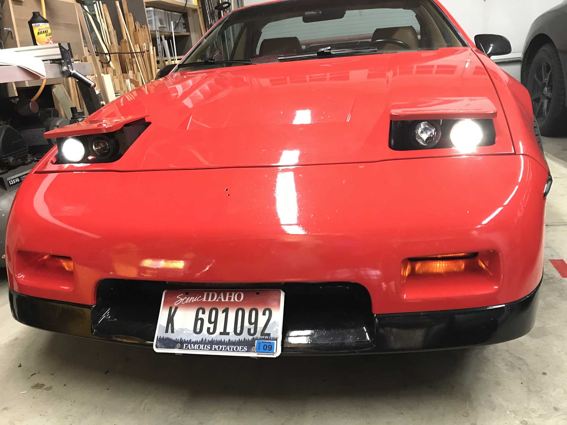
Time for some results, Low Beams
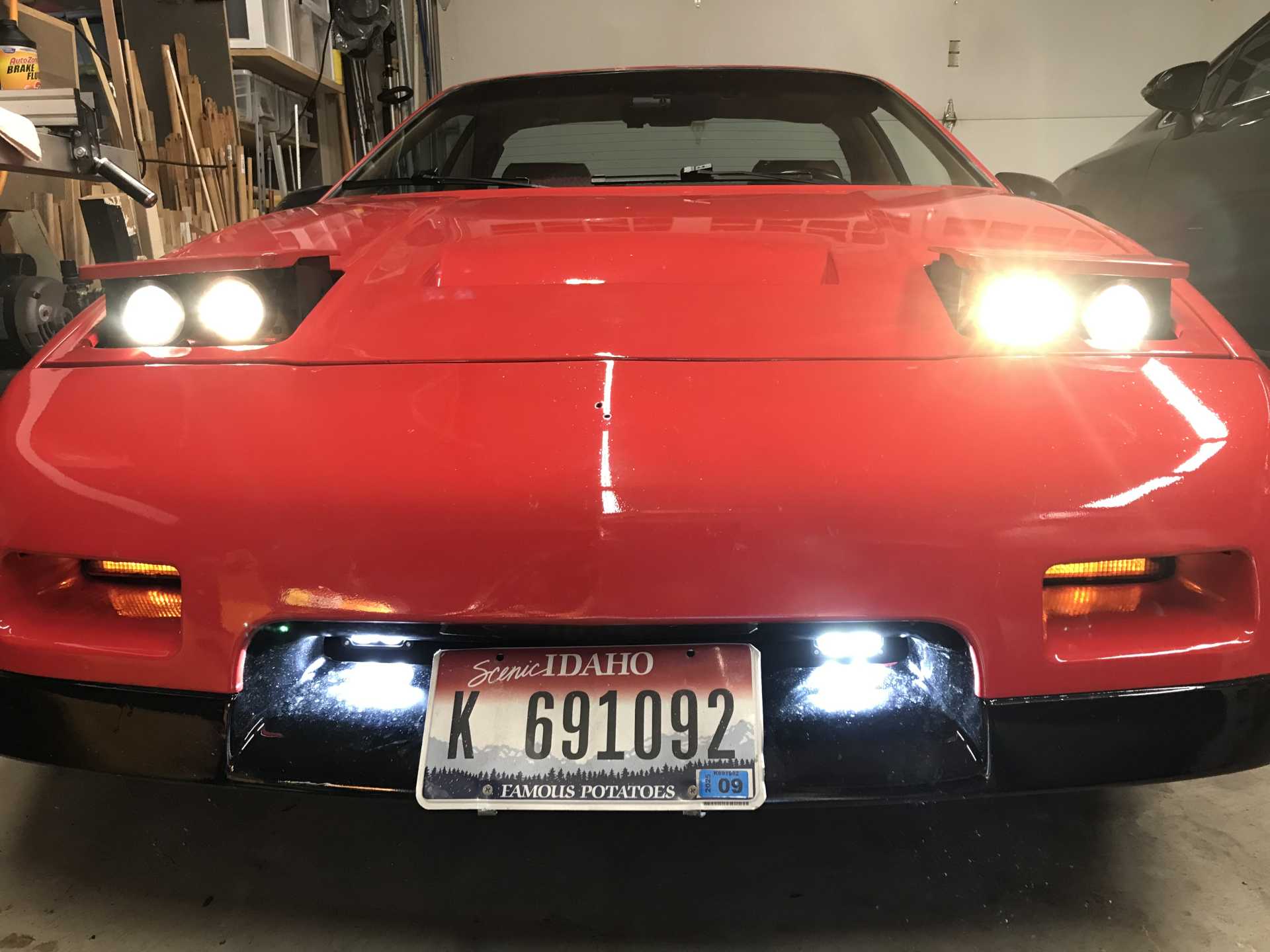
High beams with low also active and add-on LED lamps below
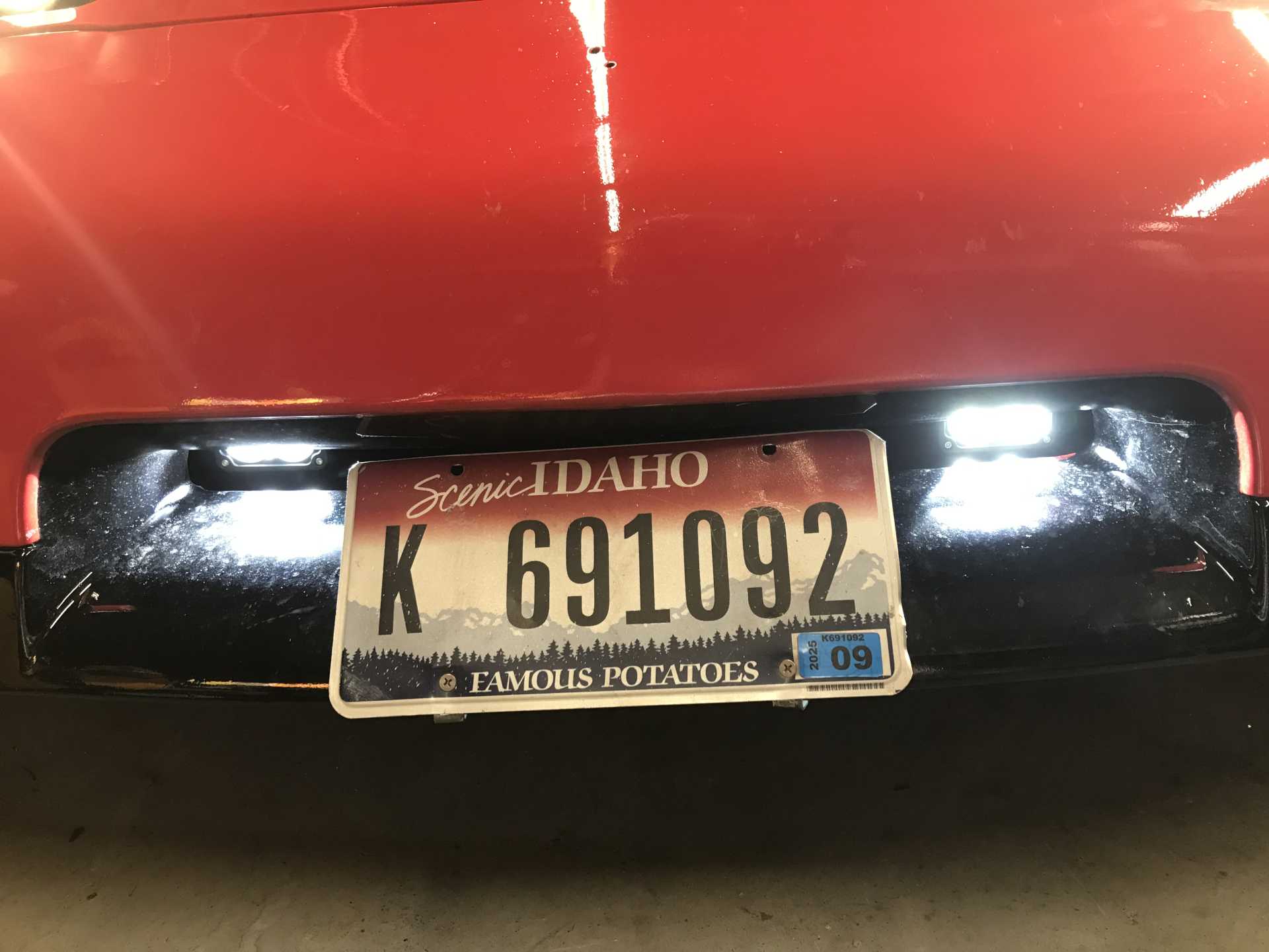
Added 20 W per fixture 3" x 1.8" LED lamps that operate with high beams. From Amazon for about $30 per pair using Cree LEDs, Cree makes really good LEDs, I used them oin my elevator work without problems. These are true spotlights with tight beams. They bolt onto the cross member behind fascia.
Final thoughts. I'm very pleased with the results, the new lamps are vastly superior to the old sealed beams. It took about 30+ hours to complete so it isn't a quick project. It appears there are no currently offered 90mm bucket products on the market. One of these days I might try MIG welding one up to make it look more presentable. It was a lot of trial and error to get everything to fit and operate correctly. The new motors are great. Finally I tried a pair of Sylvania 9005 LED lamps and was disappointed. The LED light dispersion from the LEDs does not match the 90mm high beam enclosure and the light is very irregular.
Coming soon(ish) Paddle Shifters!
But first there is a followup on the lamp covers below!
[This message has been edited by MikesFirstFiero (edited 03-27-2024).]
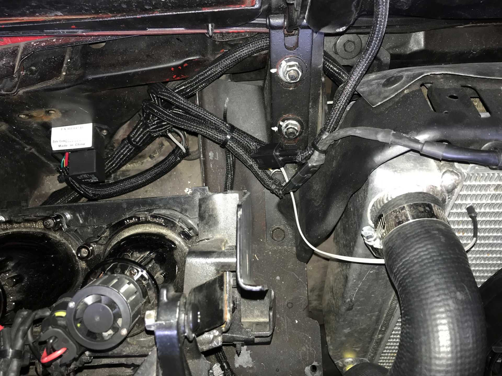
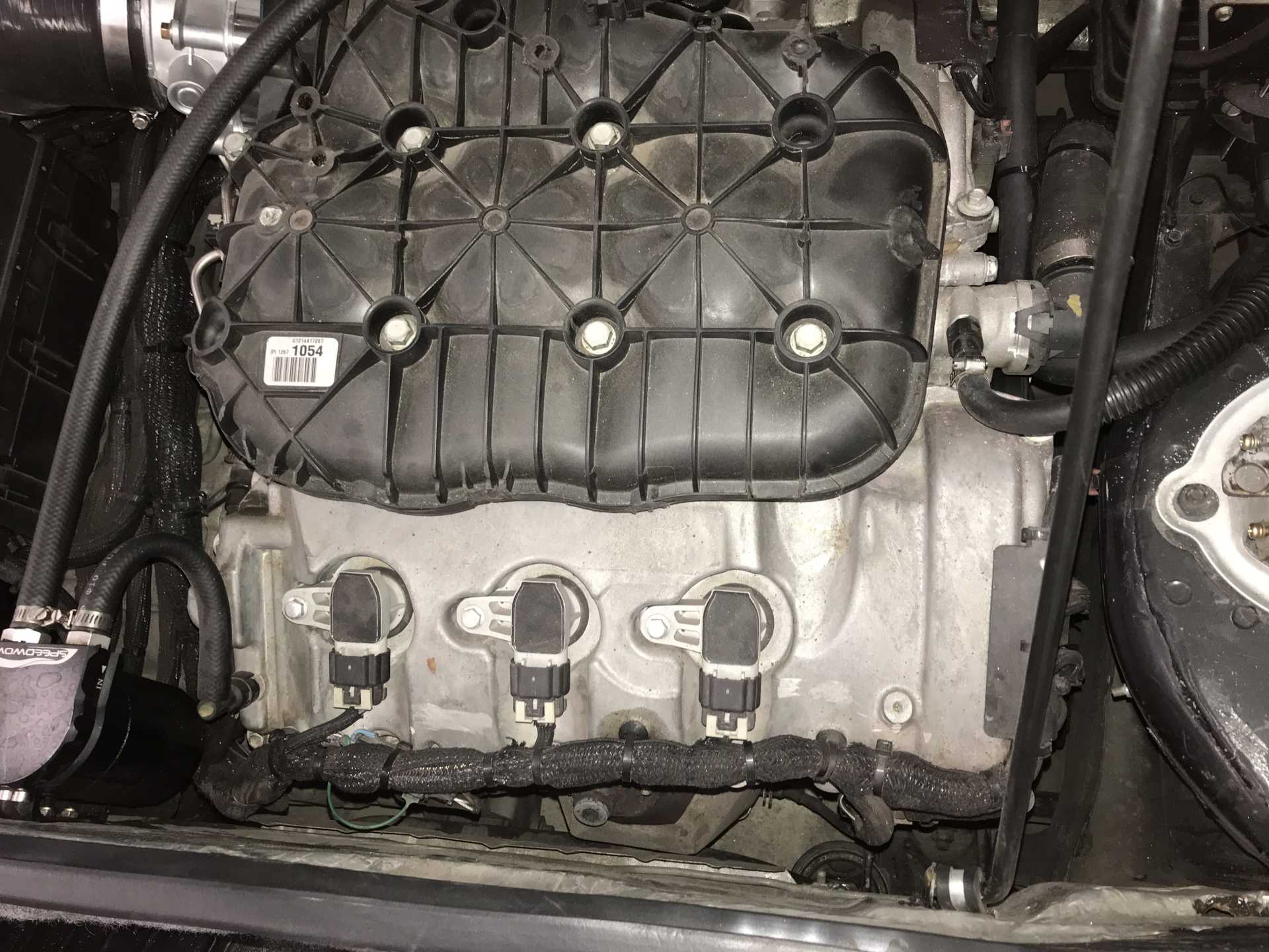
Yes, the FPCM is included in this car. It lives on the right side of the engine bay, just in front of the relocated coolant overflow tank. I really need it for the gas gauge on the Impala cluster to operate. It also provides the emission controls which are correctly installed. The FPCM can modulate the fuel pump pressure from the in-the-tank pump but I have disconnected that feature a while ago when trouble shooting my mis-fire problems. Fuel pressure is now a constant 55psi regulated by a Corvette fuel filter with internal pressure relief return line back to the tank. My OBD-II reader shows that the live puel pressure remains at 55PSI at all times.
The only changes to the engine system are no third cat converter downstream, Revised exhaust, larger throttle body, different air filter/induction system and tuning to make it run correctly with those changes. I wanted it to run well around town and on the road, be economical to run and be quick. 0-60 in low 5's is fast enough for my purposes and 35mpg at 70MPH cruise is also great. If I really wanted to go faster I think I'd go to an LS4 which can be modded much easier than this engine. The critical things in all this build for good engine performance are: All air into the engine is metered including crankcase ventilation; No hose bends or kinks to air flow before the MAF and having the engine/transmission controllers properly tuned.
I'm still trudging through an LF3/LF4 swap and finishing up exhaust currently but eyeballing the upcoming fueling hurdles (and intercooling in my case).
I assume you disassembled the bucketed fuel pump assembly and just attached the pump to the fiero pump assembly and utilizing the included pickup filter.
Good solution on the pressure relief valve back to the tank..
Found an absolutely excellent site and article that covers the ins and outs of running a returnless PWM fuel pump setup when you don't have room to fit one of GM's self contained fuel modules, i.e. the fiero fuel tank
The last word any good engineer ever wants to hear is "just". Look back a couple of pages and you can see the mounting od the pump was simple. But the intake of the impala fuel pump is different from a normal fuel pump. I had to keep a plastic fitting from the original Impala module to make it work. I did reuse the Impala intake screen. The Corvette filter/regulator has worked without issue. I've now got 10K miles on the conversion with no fuel issues. I did use the FPCM to modulate the pressure at first and then changed it to directly feed from 12V while fighting the misfire problems. Did not seem to make any difference with higher pressure at all times. I really kept the FPCM to have a functioning Impala gas gauge. And the emissions are intact too.
I've now discovered a small leak on the tank vent pipe to the filler neck. I'll be pulling the tank in the spring to braze this back in place, the old solder just gave way. I'll check the pump as well since I'm already in there.
We have had a very cold January with overnight temps of -10 to -20 F for a week. Working second shift at O'Reilly's means I cold start at 9:30PM. It has not ever failed to start. and those new headlights are great when it's dark outside with no street lights.
I checked out the VaporWorx site. I gives a good explaination for fuel systems for port & TB injection. The Impala system is direct injection with the 55PSI feeding the engine driven high pressure pump & injectors up to 2000PSI. There is no regulator on the high pressure side, it must be internal to the HP pump. The original Impala low pressure regulator was part of the complete fuel pump assembly along with the filter and level sensor. Meaning if anything fails or the filter is clogged you are looking at $300 to replace the in the tank unit. The high pressure pump has options from $300 up to $700. Ouch.
[This message has been edited by MikesFirstFiero (edited 02-28-2024).]
All good as your system is working really well now... I was pointing to the site that explains in one location regarding the elements of moving from a return system to a dead head or returnless. Specifically around having a check valve but also having a fuel over pressure system for when the lines heat soak. The fuel modules have an over pressure regulator and check vavle already in place.
The fuel modules also have a rather efficient way of sucking fuel from the tank by the use of venturi pumps powered by a controlled leak out of the pump utilized for low demand pump flow stability via pwm. The venturi obtained fuel fills up the bucket around the pump so the pump is always submerged, keeping it cool and improving pump efficiency due to temp but also more efficient pickup due to always being submerged. The venturi / bucket system can literally suck the tank dry.
You can get an OEM gen 6 camaro zl1/ss fuel module from rock auto for 120$. But yes, the hpfp's are steep. The Ats-v pump is 400$ at best price I could find...
Now the question for me is how to incorporate all these features into the fiero fuel tank.. Lol
[This message has been edited by msweldon (edited 03-02-2024).]
Nice work, be careful with the Fiero driving in winter and rust. My Fiero had never seen snow (200K miles) and was pretty rust free in the upper and lower rear frame rails. I drove it for one winter in MA, and now upper and lower frame rails are rusty. Granted I did a lot of snow drifting where salty snow was getting chucked everywhere, but I don't think the factory chassis paint is the greatest. Eastwood makes a great internal frame coating paint, can't get the link to work for some reason but it is: ITEM # 15275ZK. Comes with the 3 foot long whip with a 360* nozzle. Ain't cheap at $30 a can but you get what you pay for.
I will be using it on my Fiero, and have used it with good success on other cars in the past. Very watery paint though to let it get into all the cracks and crevices, but keep that in mind when using it if you ever get some.
I have also successfully used zip ties for CV boot clamps on my WRX, I use two and offset the heads 180*. Used on the large and small end of the boots. They have held up just fine for 40,000 miles, and seen 130+mph many a time. Got sick of leaking factory clamps. Bought some high strength zip ties from McMaster, not even sure if that is necessary though.
I like how your headlights turned out too!
[This message has been edited by zkhennings (edited 03-08-2024).]
The Fiero fuel tank is really a pain. Not enough capacity and long & skinny so the fuel can slosh away from the pickup. The idea of using a venturi to fill a small cup is clever. I'm thinking that the Impala had a similar solution but the impala unit would never fit into the tiny tank opening. So when I plan to drive quickly I make sure there is a half tank minimum.
I'm planning on going over the frame rails and check their condition. Putting in a rust preventitive sounds like a very good idea. Around here they use some kind of a de-icing fluid on the roads but only on interesctions, roundabouts and highways. Other roads are simply plowed. We don't usually get more than 6-8" in any one storm so the roads may be slippery but they are usually drivable. Since I go to work at noon and drive home at 9pm there is little traffic to contend with. And it's only 3 miles each way. If the weather is really bad I'll take our Toyota AWD Venza.
With winter coming I replaced the wipers with Rain-X Rugged ones. Pricey and NOT worth the money. Rugged they are not. Replaced with Bosch Pure Vision (we had them on a 2-for-1 sale). These seem to be holding up much better. Also determined that the driver side wiper can be 21" and the passenger 19" to give better coverage.
The new headlamps are working well but need some tweaking the aiming. But it's too cold to do it on a deserted road now. Maybe in April. While I like the results it was really a time consuming pain. If someone offered the 90mm buckets again I'd buy them before modding the originals.
Just changed to summer tires and did a quick check under the car and found nothing wrong. The CV boots are still well retained and there are no new leaks other than the already discovered vent pipe.
[This message has been edited by MikesFirstFiero (edited 02-20-2025).]
I *think* the main problem with the fuel tank is the baffling system inside is plastic, and breaks apart easily. I know in my tank the baffles are all broken and don't hold any fuel around the pump anymore. There is a really steep really tall one way road off main street in Worcester MA that I got stuck on once, I had a 1/4 tank of fuel and halfway up the hill the car died from all the fuel running to back of the tank. I had several people behind me and we all had to back up into main street, and I had no vacuum assist for the brakes exiting backwards out of a one way into a very busy road. Fun times!
I believe Rodney D's replacement tanks have all metal baffling and the pump sits in a little sump to solve these fuel issues and higher capacity, I think they are pretty well priced too and bolt right in. I am strongly considering buying one. Edit: looks like he does not have anymore and is not making anymore, he is selling the tank making business, but maybe a member has one for sale.
Putting the tank under the center spine is a clever way of utilizing that space - and an awful solution for providing a constant fuel flow. I've had the car die when stopping quickly several times with 1/3 of a tank of fuel. It could use a way of transfering fuel surging forward back into the central baffled chamber. I'm going to pull mine to fix a leaking vent tube and might give it some thought. It is really irritating as it now operates.
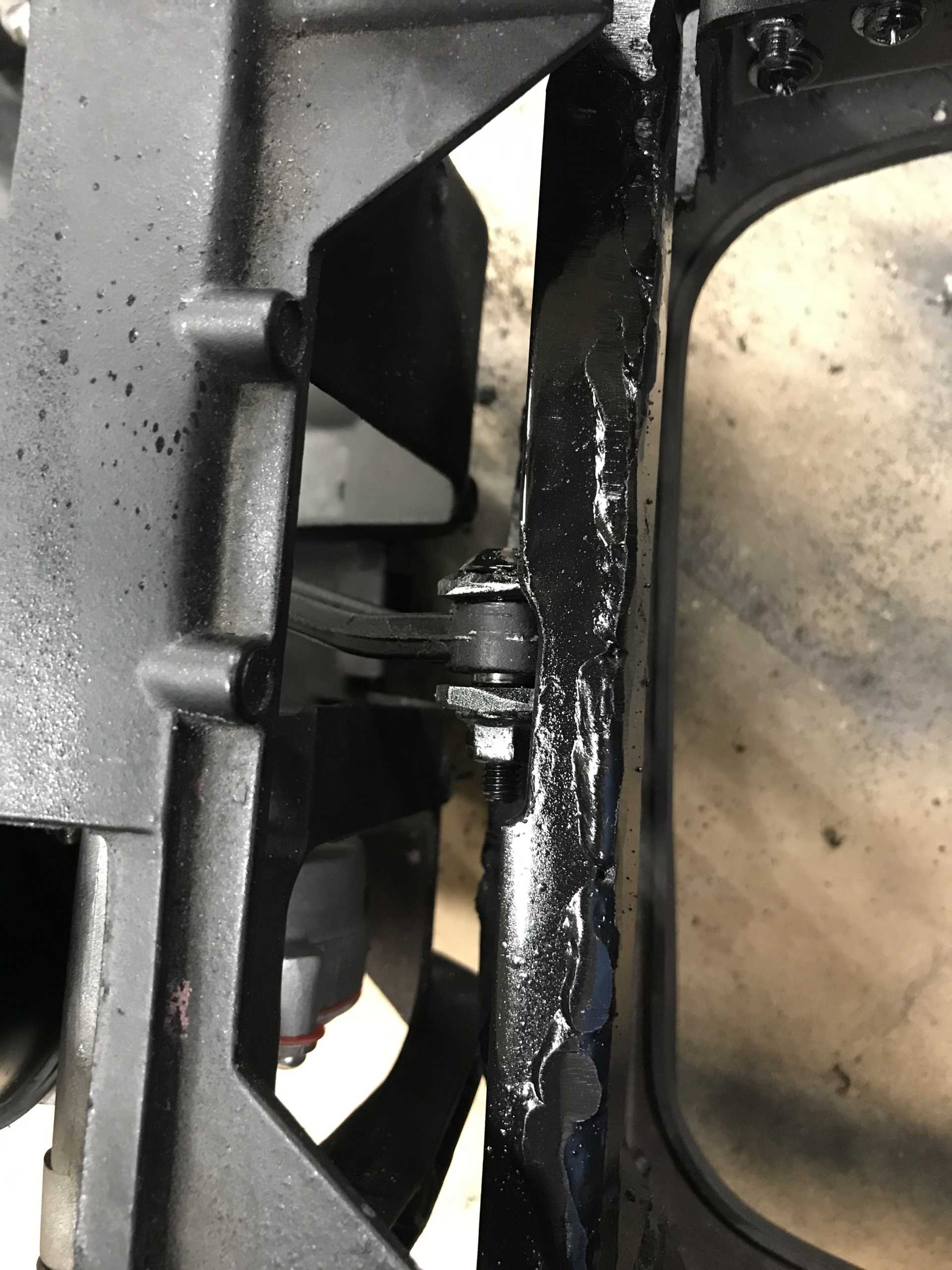
Had something popup (literally) while driving a few nights ago. Took a guy I work with for a quick ride after dark. I found the headlight lids were fine up to about 80 and then they started flopping around when going faster. The lids do have built in stops for the original lamps but it needed new lower ones for the slimmer Hella projectors. I dug out some HDPE (high density polyethlene) laying around and carved them on the bandsaw. Now the lids are mechanically stopped at the lower position. No more dancing covers. The fasteners are #6 x 1-25" cabinet screws.
The original stop, this lid is in the new open position.
The revised stop, this one is closed
[This message has been edited by MikesFirstFiero (edited 03-27-2024).]
By now You've probably thought I'd lost interest in playing with my Fiero. No, just life and work mean not as much time for playing with cars. Everything takes twice (or thrice) as long as my mind thinks it should. Here is the last year's work in one post.
First I'd thought I would answer a PM here since the answers may be of interest to others considering this swap. GTPCAR asked the following: I have started on wiring on my LFX/Fiero swap, was looking over your build thread ( excellent job as many others on Pennocks commented during your build ) and have several questions: AC control: It appears to me ( using Impala FSM ) the AC turn-on signal is sent to the ECM with a 2 way data signal from the Impala AC control module in the dash. You mentioned not using the Impala's AC control module and how you accomplished control of the compressor solenoid valve but how did you control the AC clutch solenoid? Using the Fiero AC control head would energize the clutch solenoid but without ECM control the clutch would not cycle, also that method would remove the AC pressure switch from the control circuit. Fuel tank pressure sensor: You mentioned the fuel pressure sensor located in the fuel line ( and provided photo of location ) but I did not see any mention of the fuel tank pressure sensor being added to the Fiero fuel tank. While the former is controlled by the CCM the latter has direct inputs into the ECM.
The Impala A/C has two connectors. One is connected to the Fiero A/C clutch signal. The second PWM (Pulse Width Moculation) connector controls the variable output compressor function. Unlike older on/off compressors this compressor runs continuously when enabled. The Impala cooling output is controlled by a PWM signal from the A/C controller that allows variable output. PWM signals are used with inductive loads and are able to produce a net current that varies depending on the pulse width percentage. With a 50% high - 50% low signal the net current is zero as seen by the electro-magnet in the compressor. With a 75% high - 25% low signal the net current is about 50% of rated coil current. This produces 50% magnetic force giving 50% cooling output. When the full output is required the PWM percentage is about 95% high - 5% low. The frequency of the signal does not much matter as long as it is "fast enough" to have the coil not saturate. These PWM devices are used in many applications and are generically known of as PWM inverters. I used them to run elevators. Big ones.
My solution was to determine coil resistance of the compressor and then put a resistor in series with it to provide about 40% current when the A/C was turned on. A bit of trial and error determined what the resistance would be, 8 ohms at 20W if I remember rightly.
I don't recall there being a in-tank fuel pressure sensor on the Impala. All it seems to wants to know is the pressure being delivered to the HP pump on the engine. The original pressure limiter was built into the Impala in-tank assembly. My fuel pressure regulator is part of the Corvette fuel filter providing 55PSI. Maybe I missed something but it works well as is.
A followup on the axle boots. I used the Gates heat shrink hose clamps on both CV boots at the shaft ends when I replaced the inner joints. Those have worked out with no movement or leakage unlike the usual crimp-on metal bands. I notice that Gates is using heat shrink clamps on complex new car cooling hose designs having several rubber hoses connected to plastic connectors. So they must believe in them. The bad news is those complex hoses can cost big bucks, but that's a trend. You don't see parts to repair an alternator anymore, just rebuilt ones.
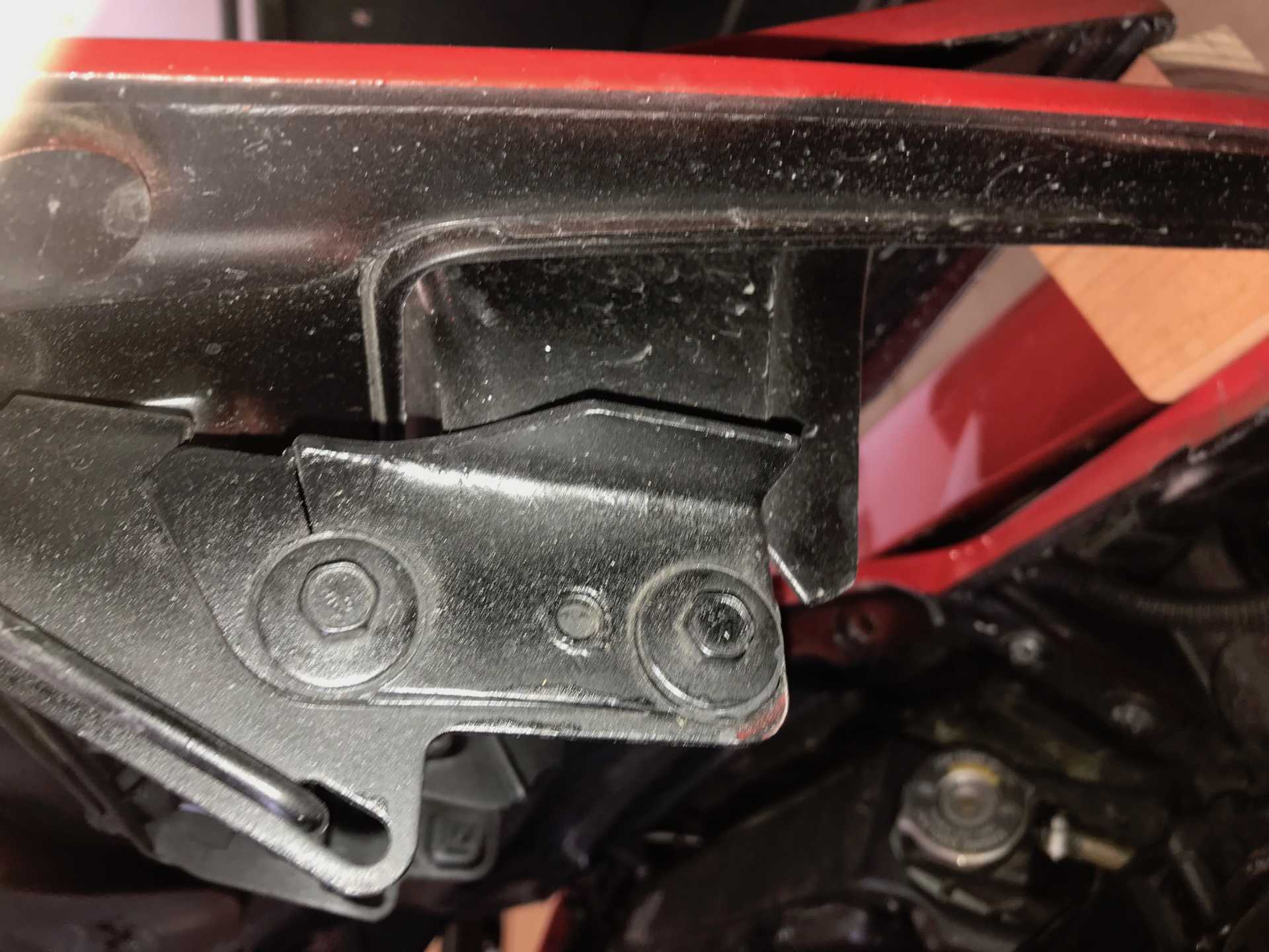
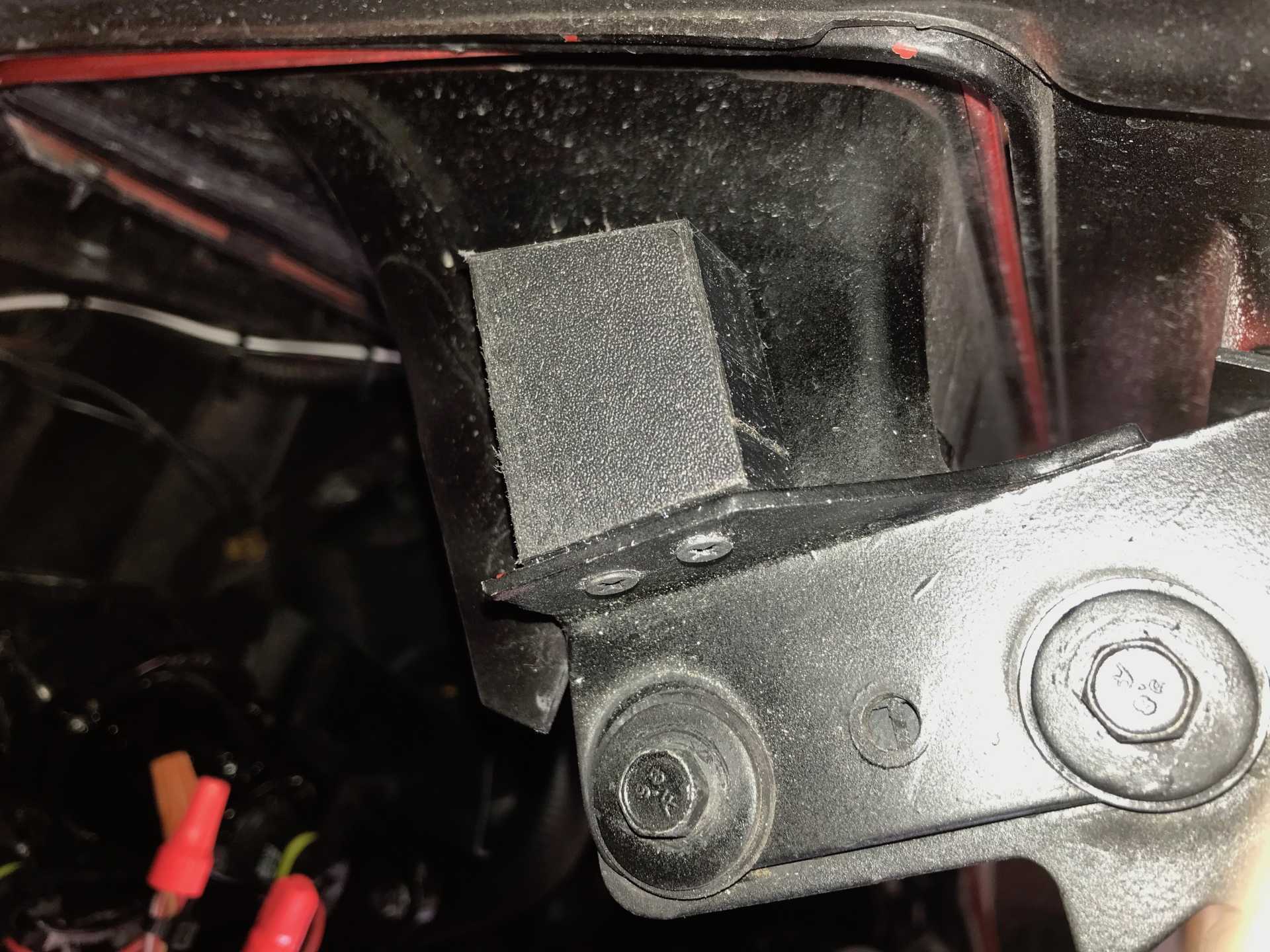
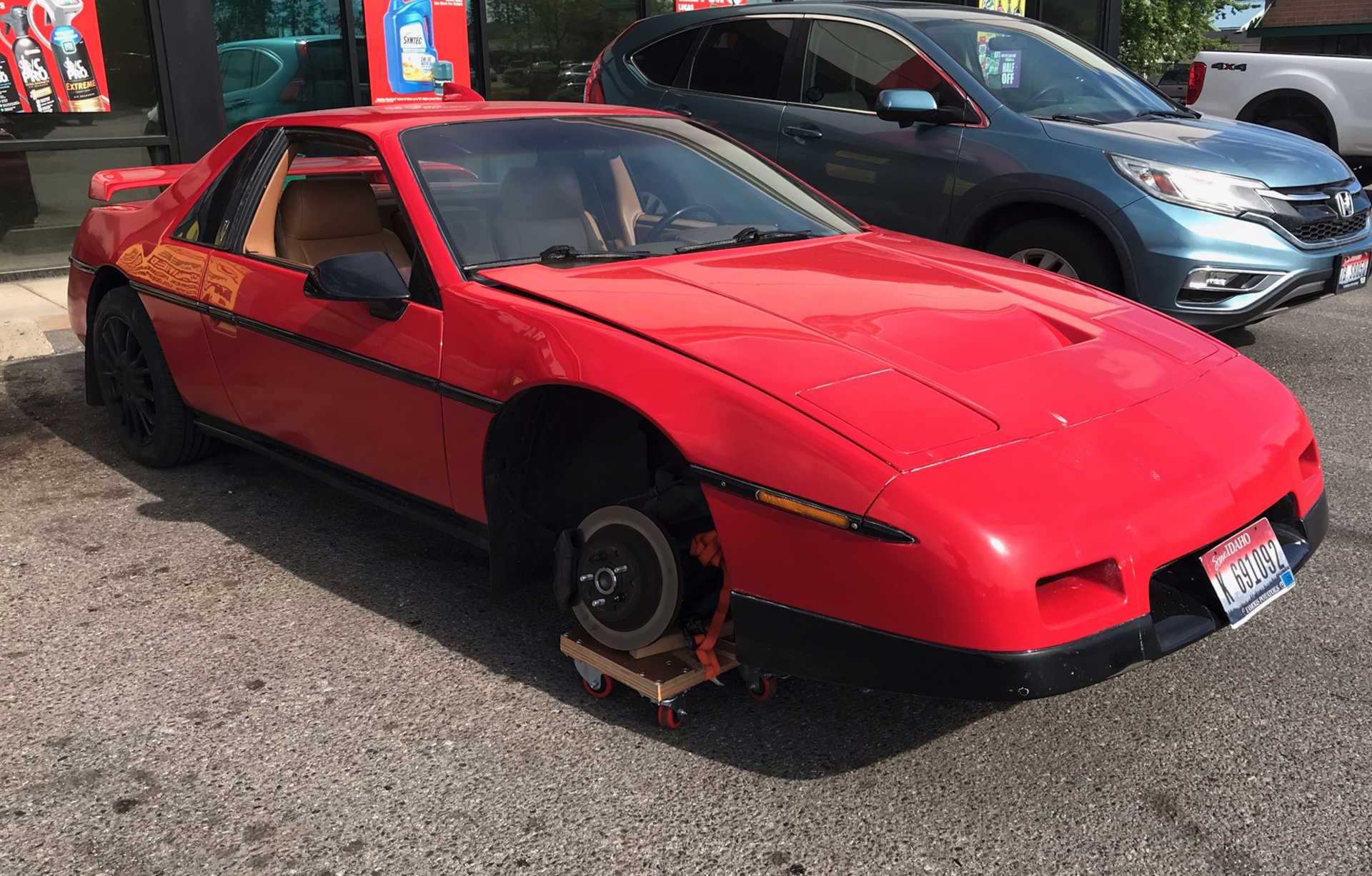
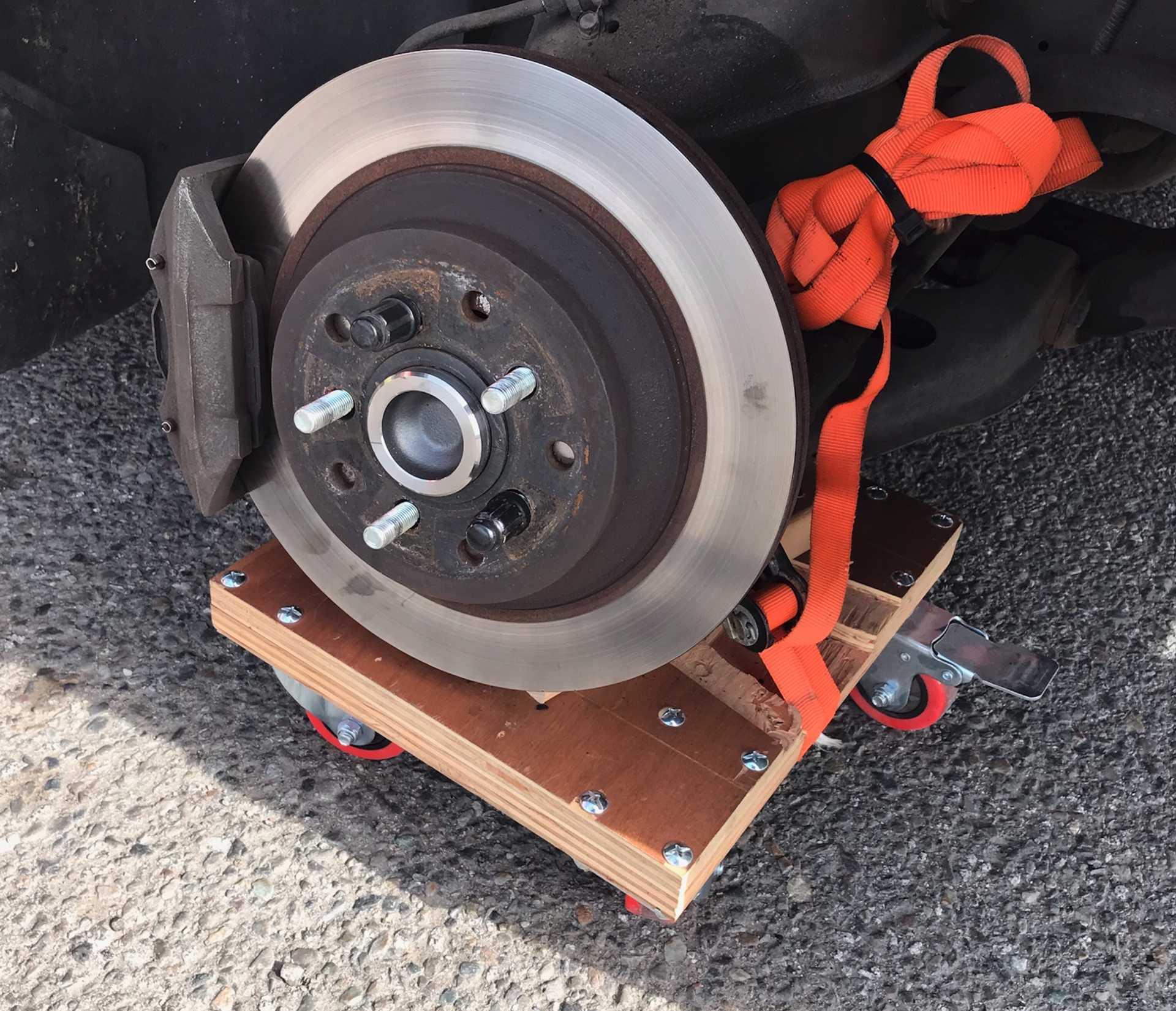
I did have one failure of note. I had cut the A-arms to clear the 14" wheels when using the lowering ball joints. That worked for a few years, then I drove to work normally (3 miles) and when I reversed into a parking slot the RF BJ separated from the arm. The wheel was turned left so it was pulled from the arm. A company named Rare Parts had original arms available so I replaced them both ($200ish each). Bad news is the new BJ is a normal one and the nose popped up. As a temporary test I installed spring clamps to remove one turn from the springs. That brought it back to about level. I'll think about cutting a turn off the coils when I do new calipers.
Put a dolly that I made for wheel alignment under the arm and slowly drove it home 2 miles. Dolly was damaged but car was not.
Just strapped it together. Had no curbs to deal with except my driveway. Made a ramp.
Since the exterior tranny oil cooler was added and the original radiator was getting old I replaced it with an all aluminum Griffin one from Summit Racing and added a new electric fan. Worked out well without any real drama. Added a new catch can for looks and added a quick disconnect between the radiator and the can. Now the coolant won't flow into the overflow can from the radiator when I lift tail of the car to work under it.
Installed a new battery since the old one was 2 years old and did not like cold winter starting. Starter would tic-tic-tic (Probably the ECU) several times before turning the motor over. I changed to a group 51 AGM which has a better CCA rating and is much narrower front to back. This gives me more room to store stuff up front. So far the starter engages first time. The standing voltage on the new battery is about 12.8V. Think the new battery is able to provide more current even in cold conditions.
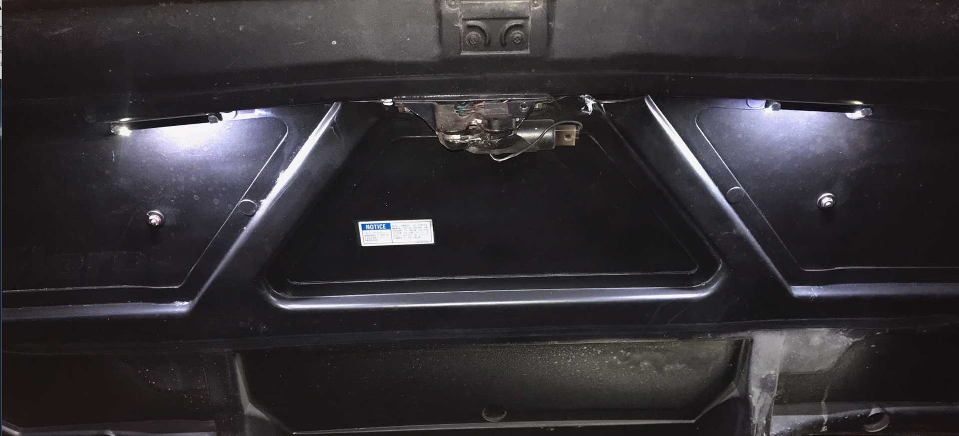
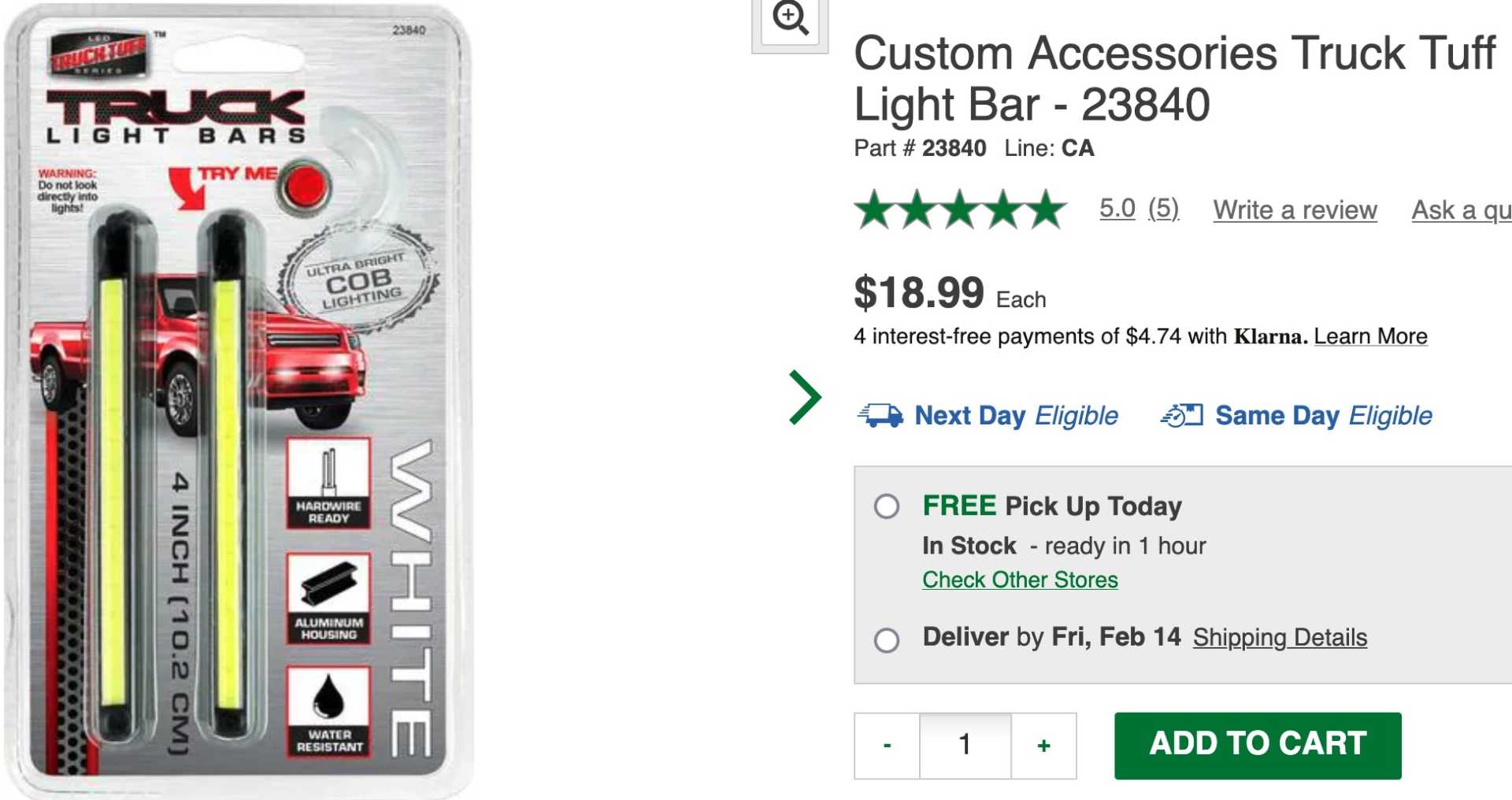
I've wanted better lighting under the hood and trunk for a long while. Then the connector from engine bay to rear lid broke. Good enough problem to make the rear trunk light, deck unlock work and add both front & rear trunk lights. I found a small set of LEDs (5 x 1/4 x 1/2") at work. These have a switching power supply that makes them the same brightness from 11V to 14V and they are very bright. Used a tilt switch up front and re-used the trunk opened switch in back to control them. The O'Reilly's part no for the LEDs is 23840. Very good results. These photos taken in a dark garage.
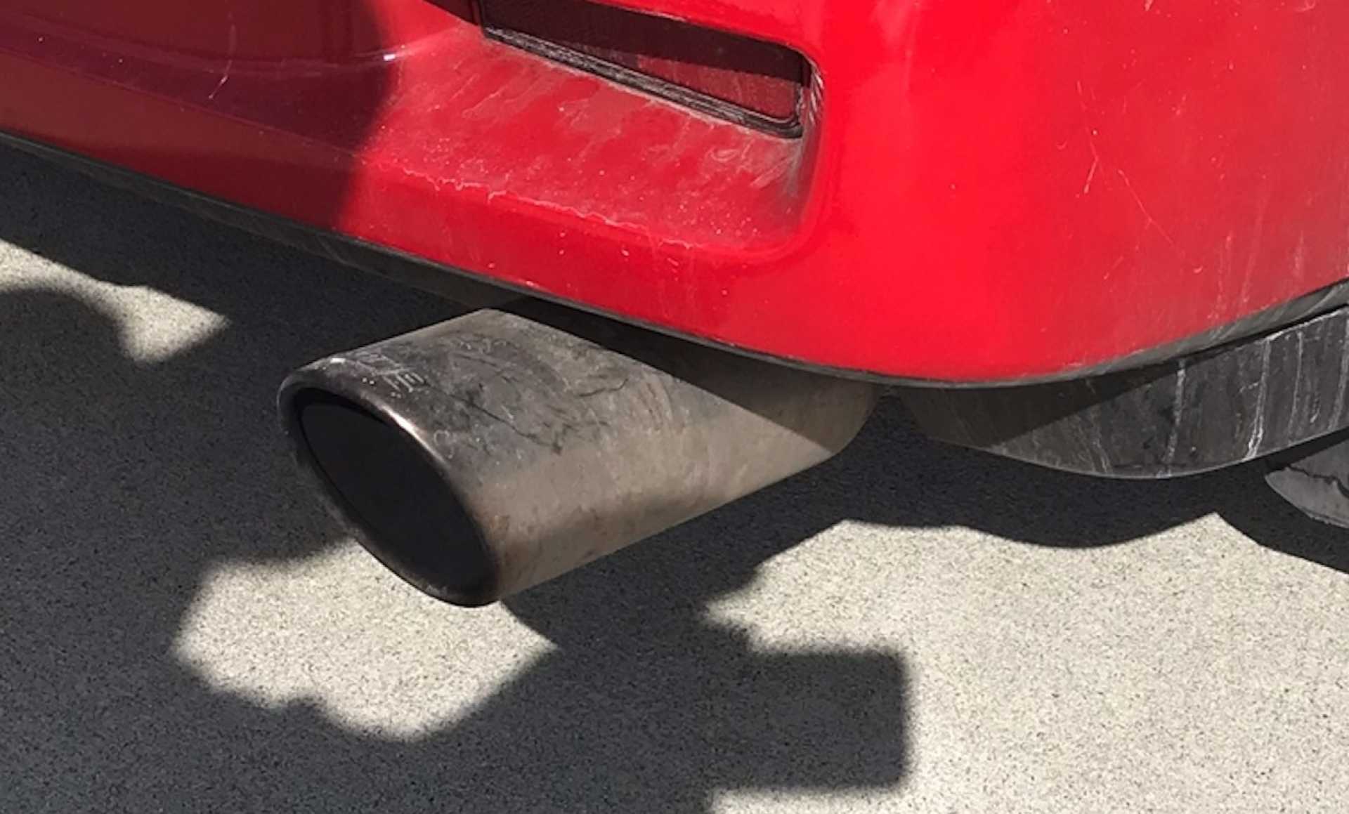
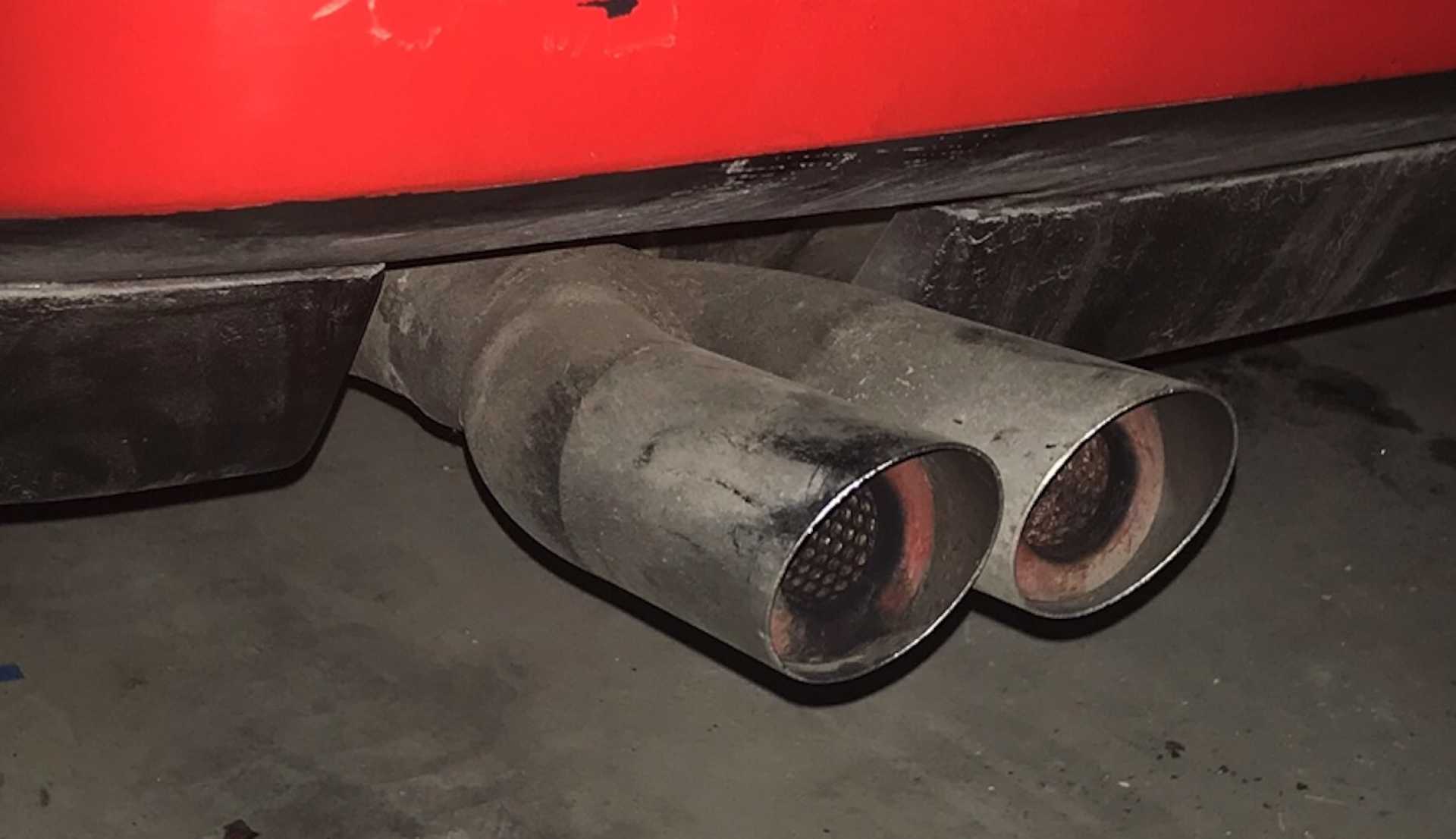
I've been unhappy with the around town exhaust sound, too loud for my taste. I purchased some motorcycle muffler packing, opened the muffler and installed the packing in the center section. Held in place with expanded metal, then welded it closed. Also removed the Borla tips and replaced with Hedman dual tips. These are much closer to the original tips design and do contain small resonators. These changes made the sound level about 6db quieter when on flat ground at 60-70. Still loud enough when I put my foot into it. And the new tips don't draw attention to the car as being modified.
Just look too big.
These look similar to the originals.
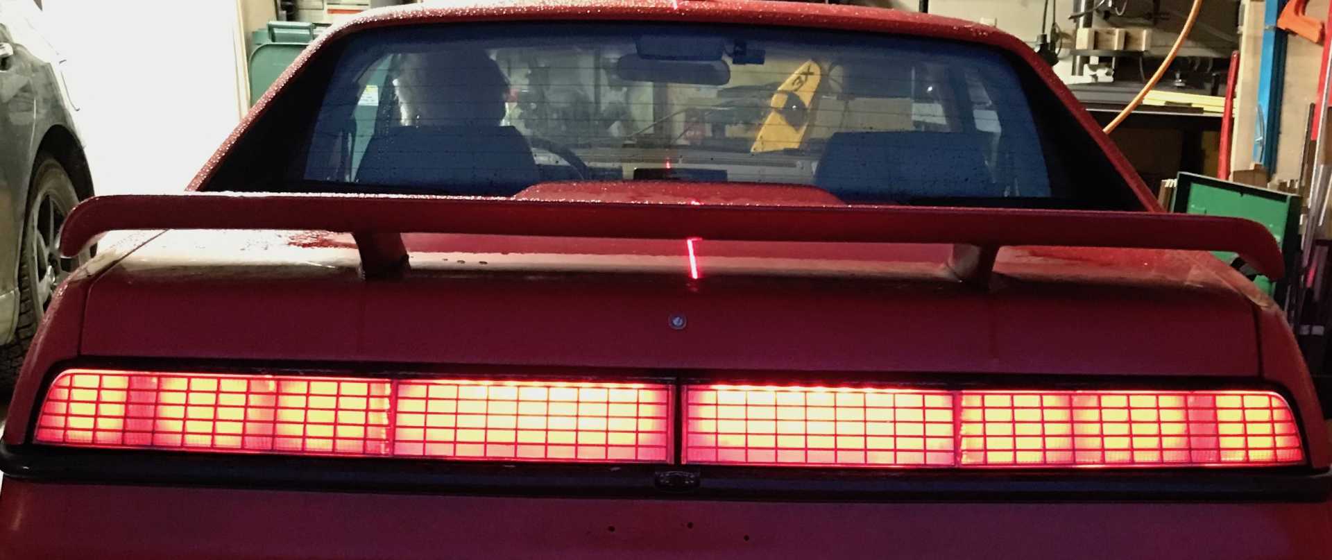
I'vealso been unhappy about the tail light covers. Too many cracks letting dirt get in. Then I found the Fiero Store has notchie style replacements in polycarbonate. Not cheap at $350 per pair but an exact match to the originals. Took the old ones apart with the old cover breaking, cleaned up all he old sealant and got to work updeating them. The lamps have all been changed to LED but the center section was unlit. Cut off the divider between the backup light and the unlit center. Added in a pair of the same 23840 LED lamps for white backup lighting and a pair of O'reilly 23805 Red LEDs for tail lights. The red strips extend into the backup light section. I added a relay so the backup lights turn on when in reverse and the Red tail lights operate with the lights on and not in reverse. Came out nicely. Added a thin translucent plastic inside the covers to diffuse the led light sources. Matched the red intensity by adding 120 ohm resistors in series with the red LEDs.
Tail Lights Only
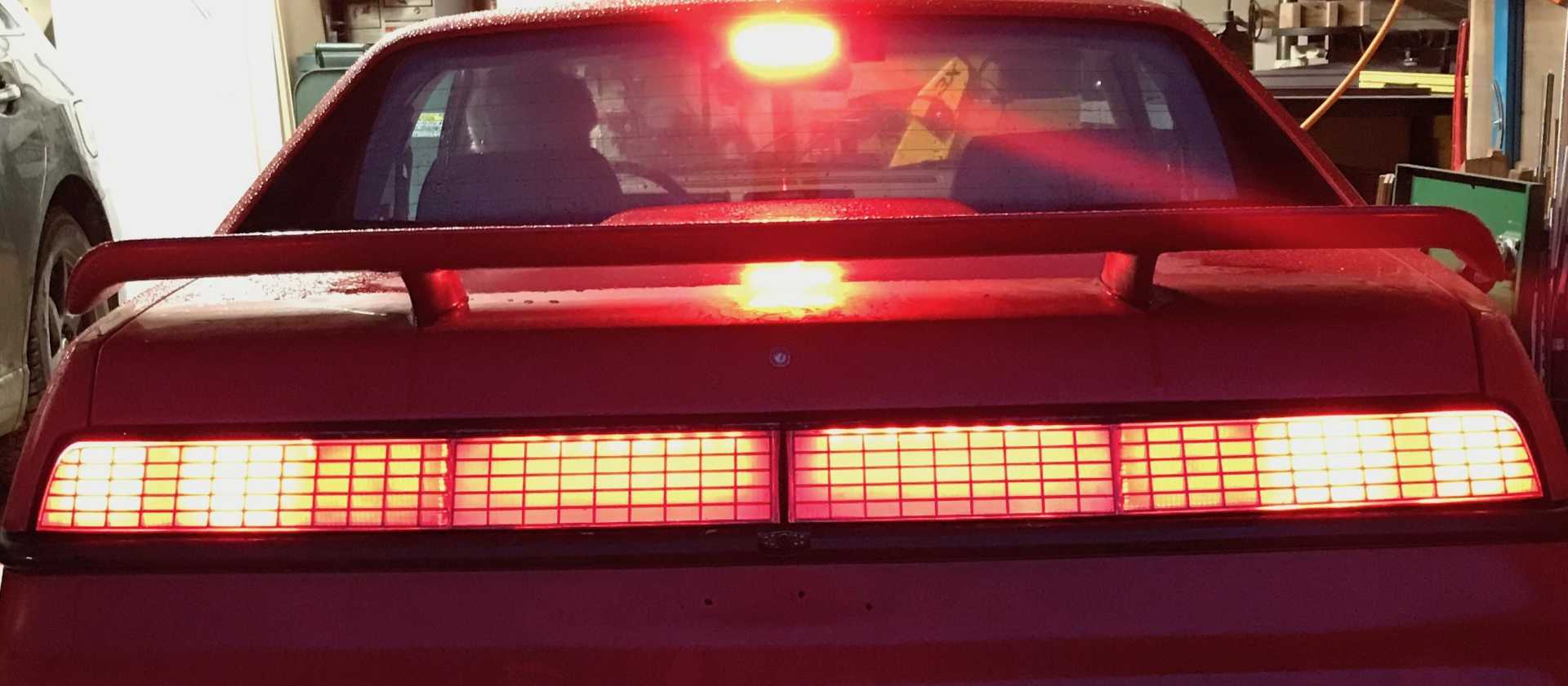
Tail and Brake
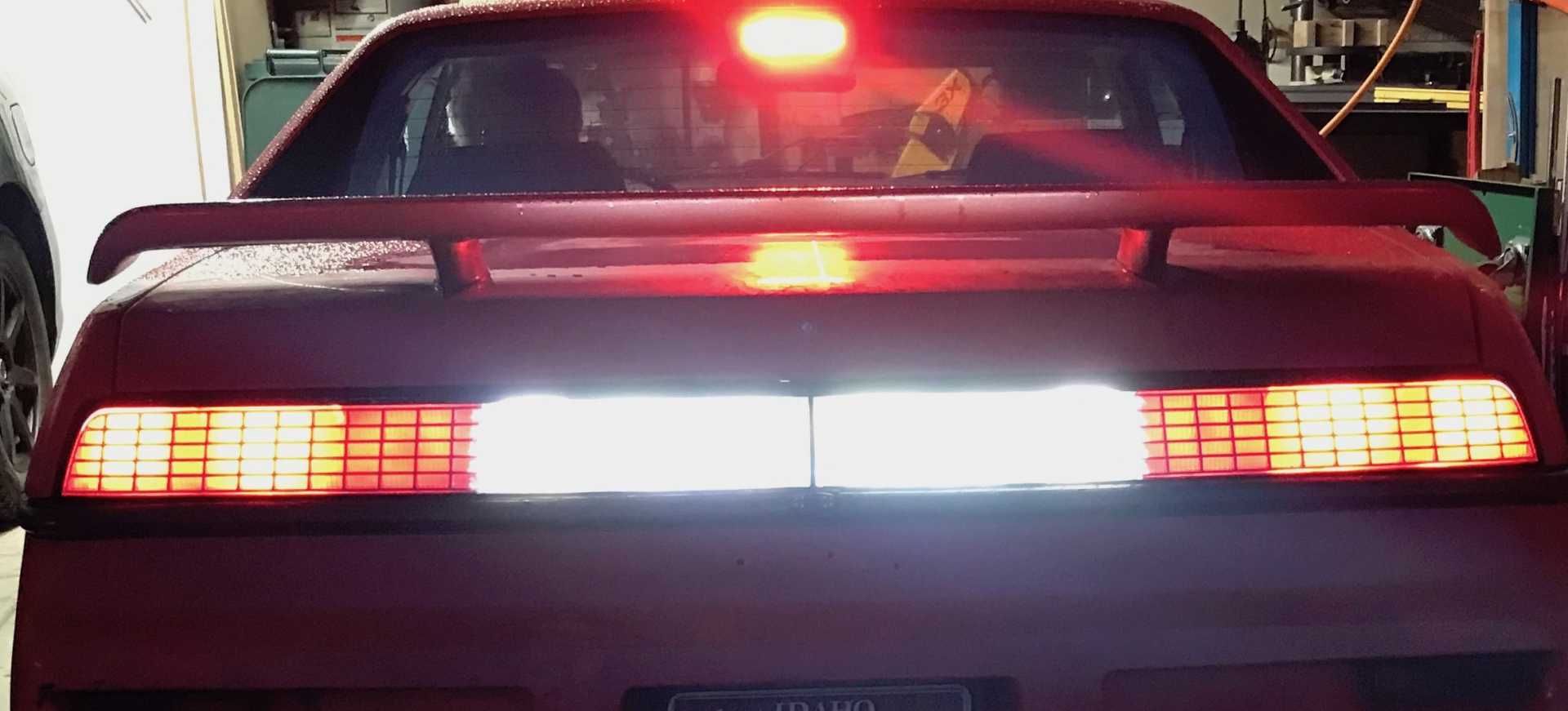
Tail, Brake and Reverse. Original reverse section now has both white and red LEDs. Center section is white/grey when lights are off
Also added a power feed for a future reversing sensors. I park bass ackwards to a concrete wall and sometimes the camera is useless with rain or dirt. The problem is mounting the sensors in the rear bumper without removing it. I may add only the center sensors in the license plate cutout
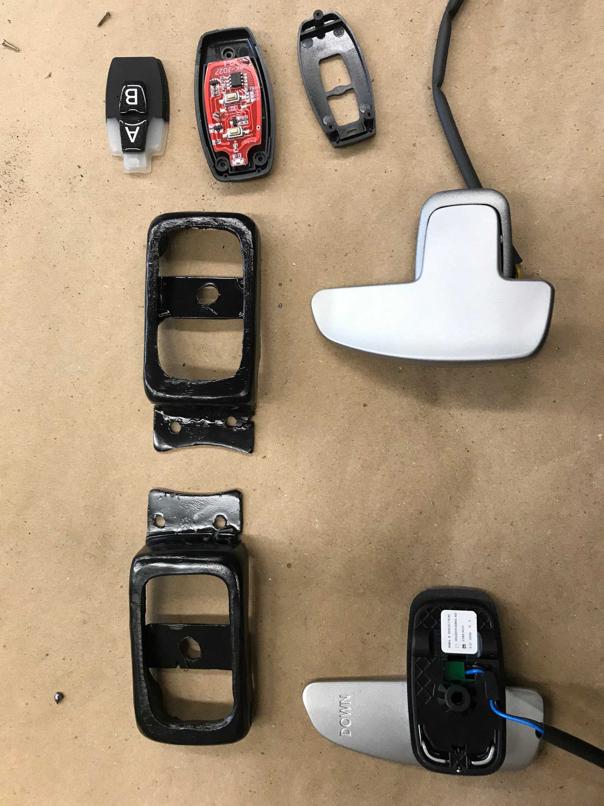
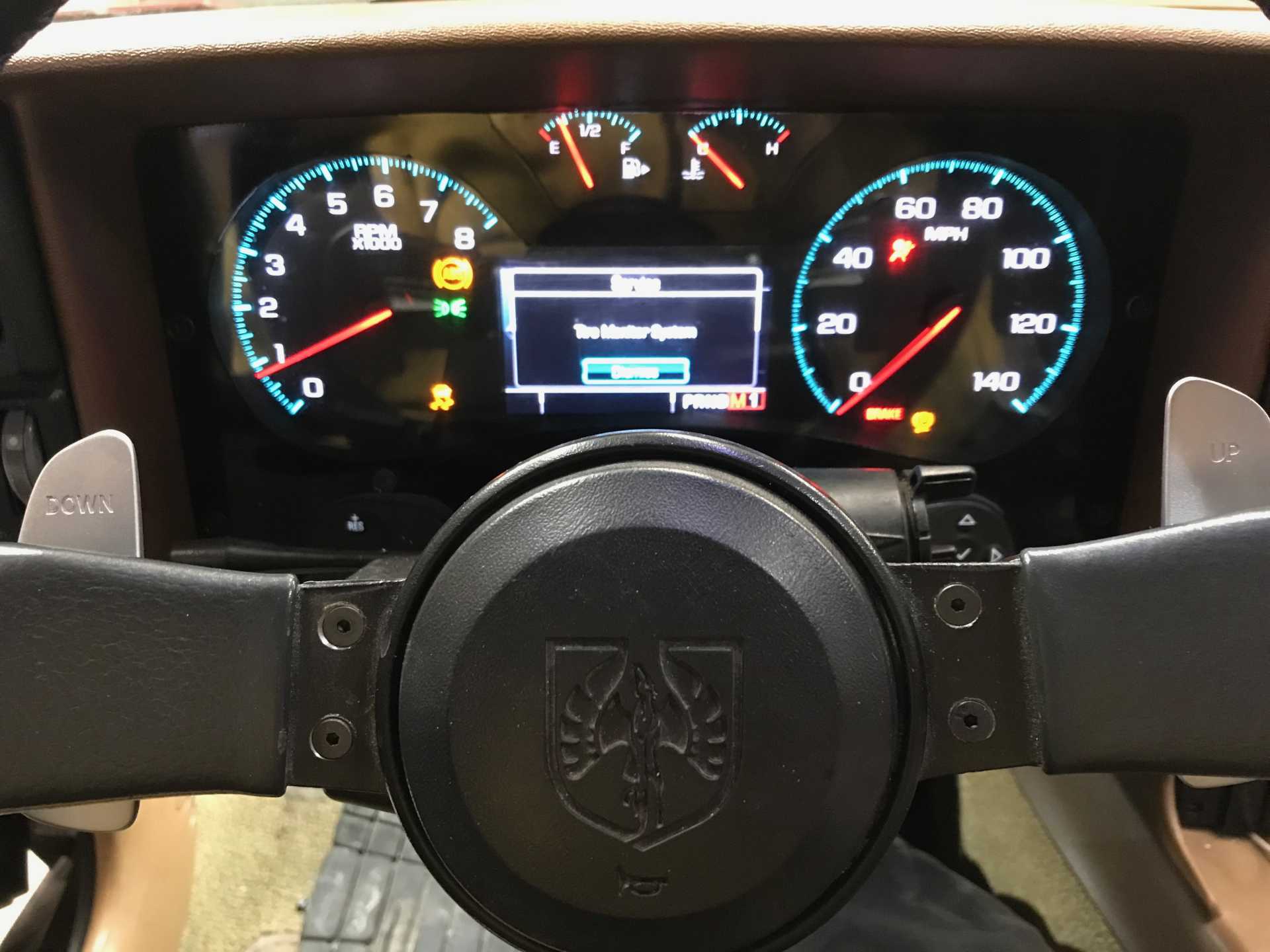
And Finally Paddle Shifters. The Impala has a switch on the shift lever for manual up/down shift but I've had paddle shifters before and like them. I found a set of good looking paddle shifters by Mercedes-Benz and bought them last year. Last year the pair cost $172, this year the cost is $248, that's inflation in action. Should be called deflation since the dollar is worth less but it's still the same switches. Now the problem is how to mount them to the 3-spoke wheel that looks good. I fabricated two metal boxes that mount to the back of the wheel and hold each shifter in place; two screws each hold them to wheel spokes. Wiring them to the shift lever was simply not possible so I decided to go wireless. Amazon had a set of two key fobs and a two-relay circuit that looked good. Bought it ($20.00 ) and was satisfied the on-off push was not delayed and did not hang on when released. Took a key fob apart and threw away the exterior metal bits. Mounted it to the back side of the third spoke with 3M double sided tape. Removed the original switches from the fob PCB and soldered the paddle wires in place. Added the back cover and it works well and looks good, has a red LED that glows when you shift so you can tell if the lithium coin cells in the fob need replacing. The receiver module was mounted in the center console with resistors added to duplicate the Impala shift knob circuit then wired to the Impala harness. And it works just as it should. With these paddles added the shift lever switch has been disabled since two sets of resistors would give the wrong values when pressed.
The Parts for the Steering Wheel
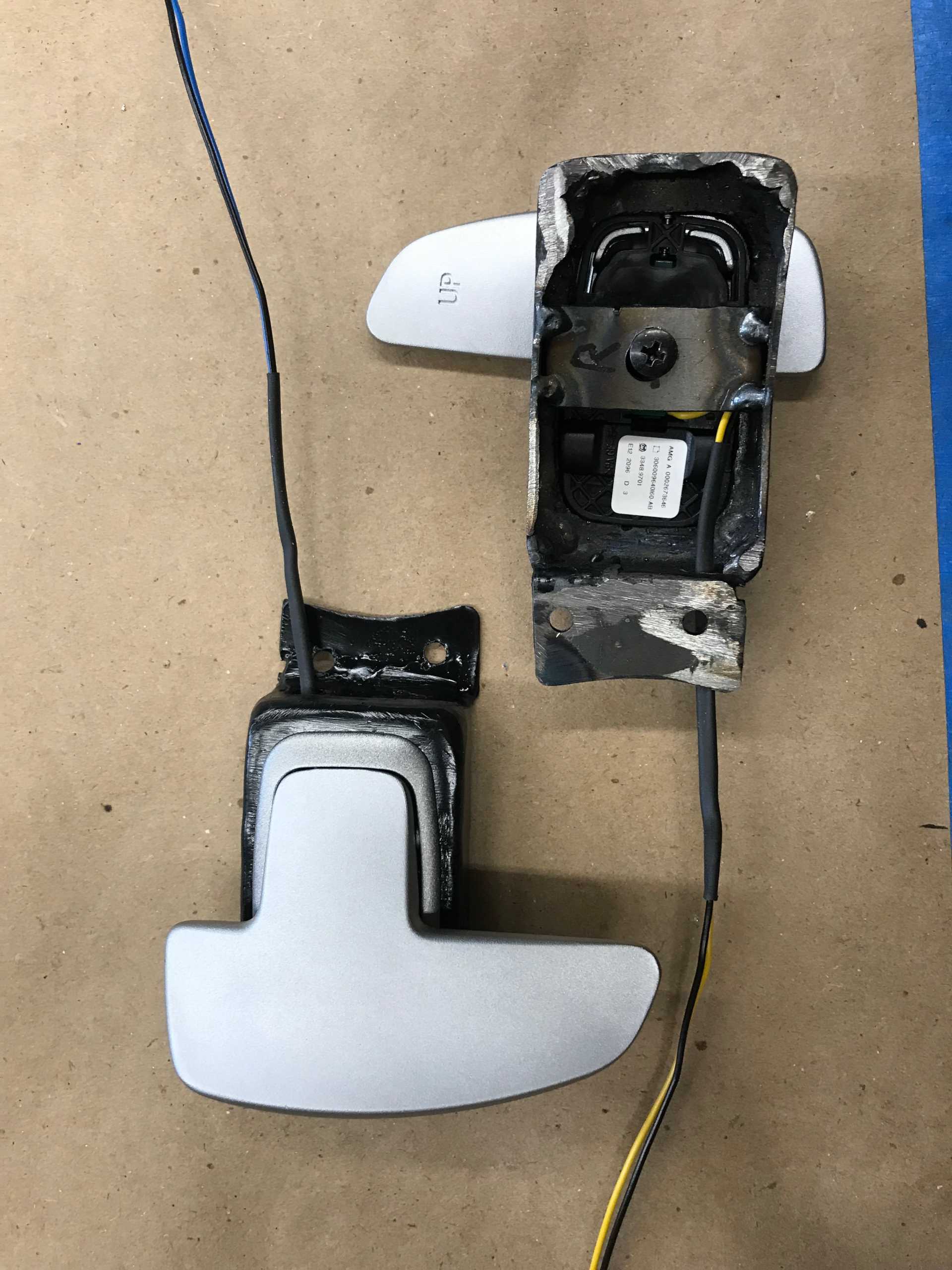
Paddle on Mounting Bracket
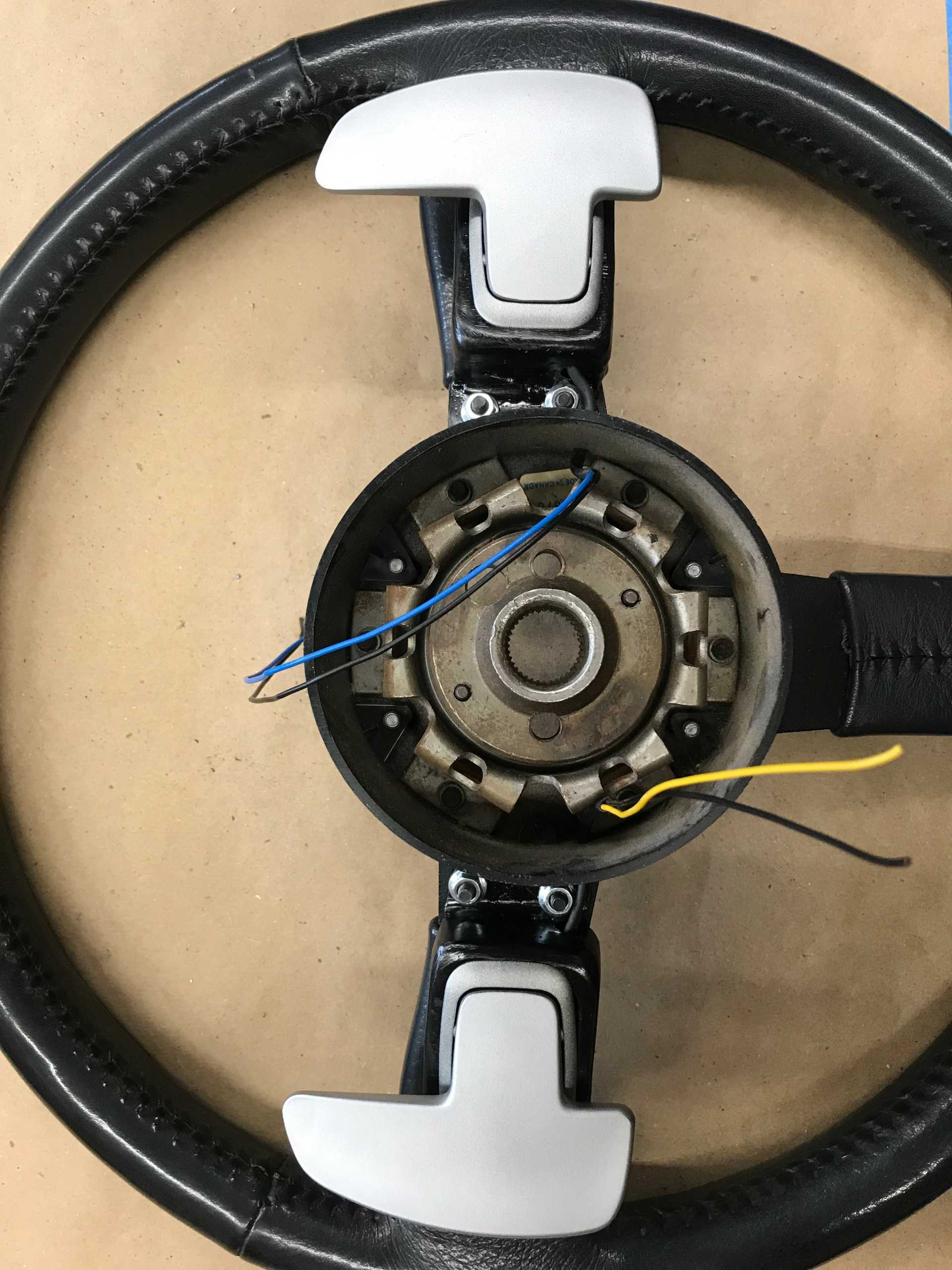
Paddles on the Wheel
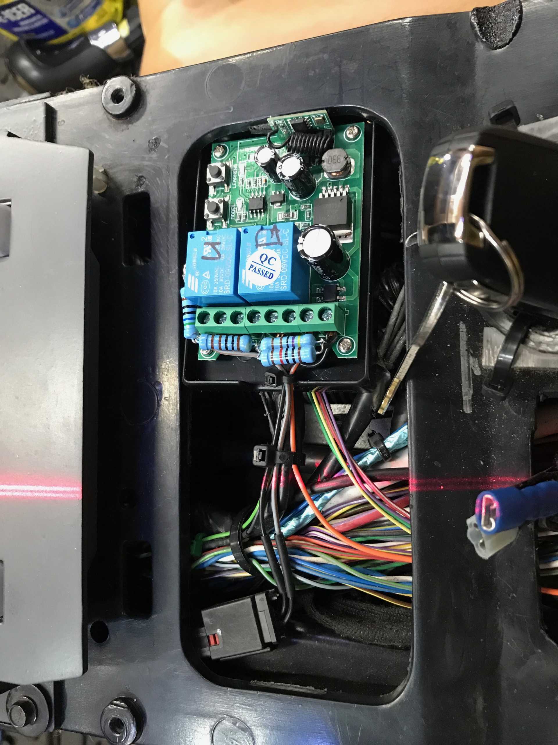
Receiver in Console, Resistors Determine which Paddle is Operated. So what's that red line? It's my parking laser. Since my parking place needs to be precise otherwise I hit the Wife's car door when exiting or run into my table saw and air compressor. It hangs from the ceiling and goes on with the garage door lights.
Not too Shabby
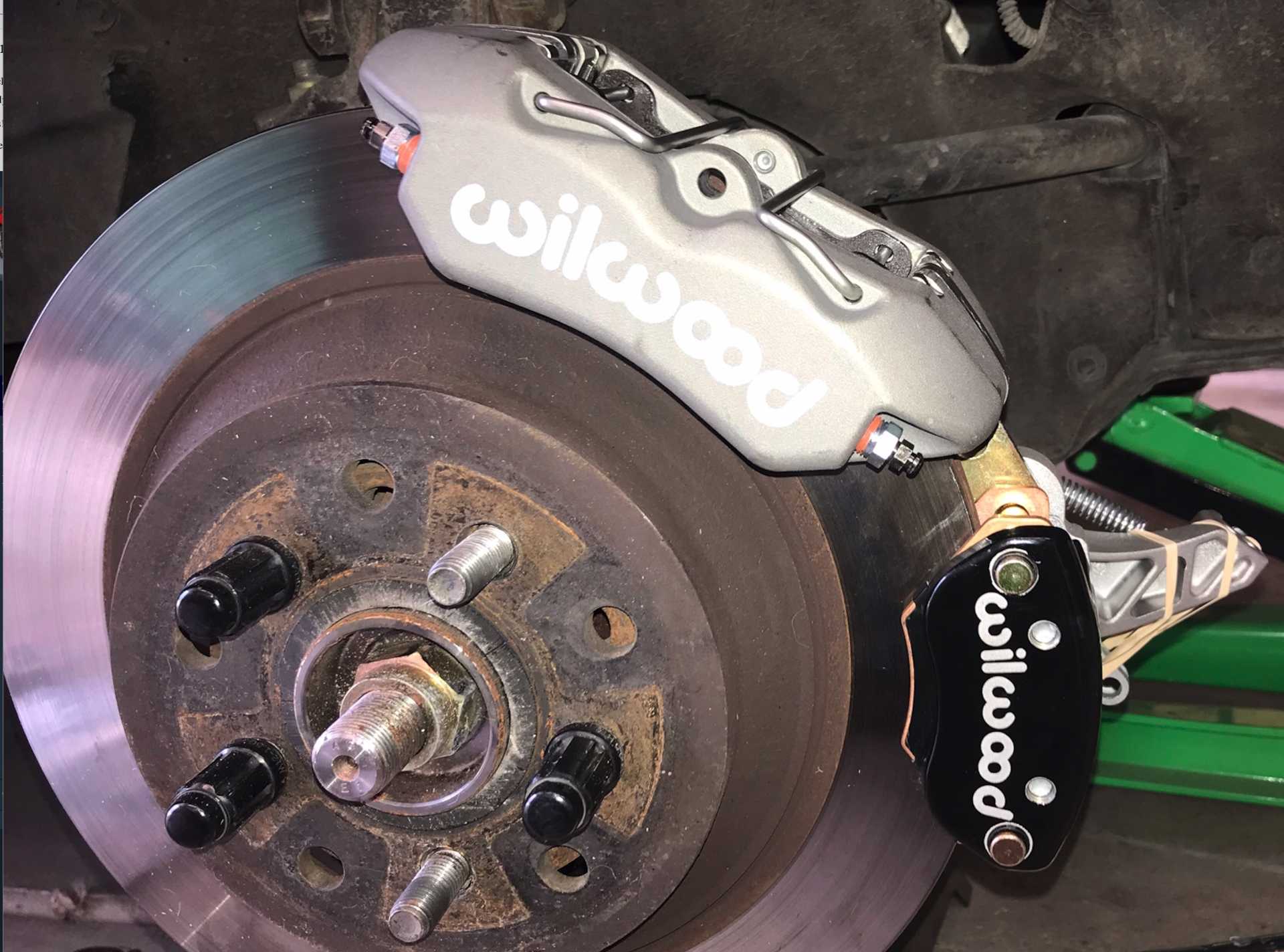
I've bought a set of Wilwood calipers to replace the old ones (all 4 + parking), a front-rear proportioning valve, a new S-10 booster and new master cylinder. I've planned the new brackets and hope to get them fabricated and installed around April-May.
The brake calipers are 121-16190 for discs about 0.75" thick. The parking brakes are 120-12069 and 120-12070
And I'm considering wrapping the car black too...
[This message has been edited by MikesFirstFiero (edited 03-07-2025).]
Been following this post and all I can say is terrific job. Wish that I had the energy to do the LFX swap but after retiring and working solo, my garage is now only used for light fabrication and repair. Keep up the great work.
------------------ " THE BLACK PARALYZER" -87GT 3800SC Series III engine, custom ZZP /Frozen Boost Intercooler setup, 3.4" Pulley, Northstar TB, LS1 MAF, 3" Spintech/Hedman Exhaust, P-log Manifold, Autolite 104's, MSD wires, Custom CAI, 4T65eHD w. custom axles, Champion Radiator, S10 Brake Booster, HP Tuners VCM Suite. "THE COLUSSUS" 87GT - ALL OUT 3.4L Turbocharged engine, Garrett Hybrid Turbo, MSD ign., modified TH125H " ON THE LOOSE WITHOUT THE JUICE "
Thanks Dennis. I am lucky enough to have an understanding wife who let me kick her Venza out of the garage for 6 months. Though she did threaten to sell it if I wasn't done on time.
[This message has been edited by MikesFirstFiero (edited 02-20-2025).]
Finally added the tail light photos to the previous post.
Just replaced the fan controller which was not compatible with the LFXCU/BCU controls, Until now fan only came on when the A/C was on. Now it turns on when the Radiator temp exceeds 160 or the A/C is on. No computer involvement.
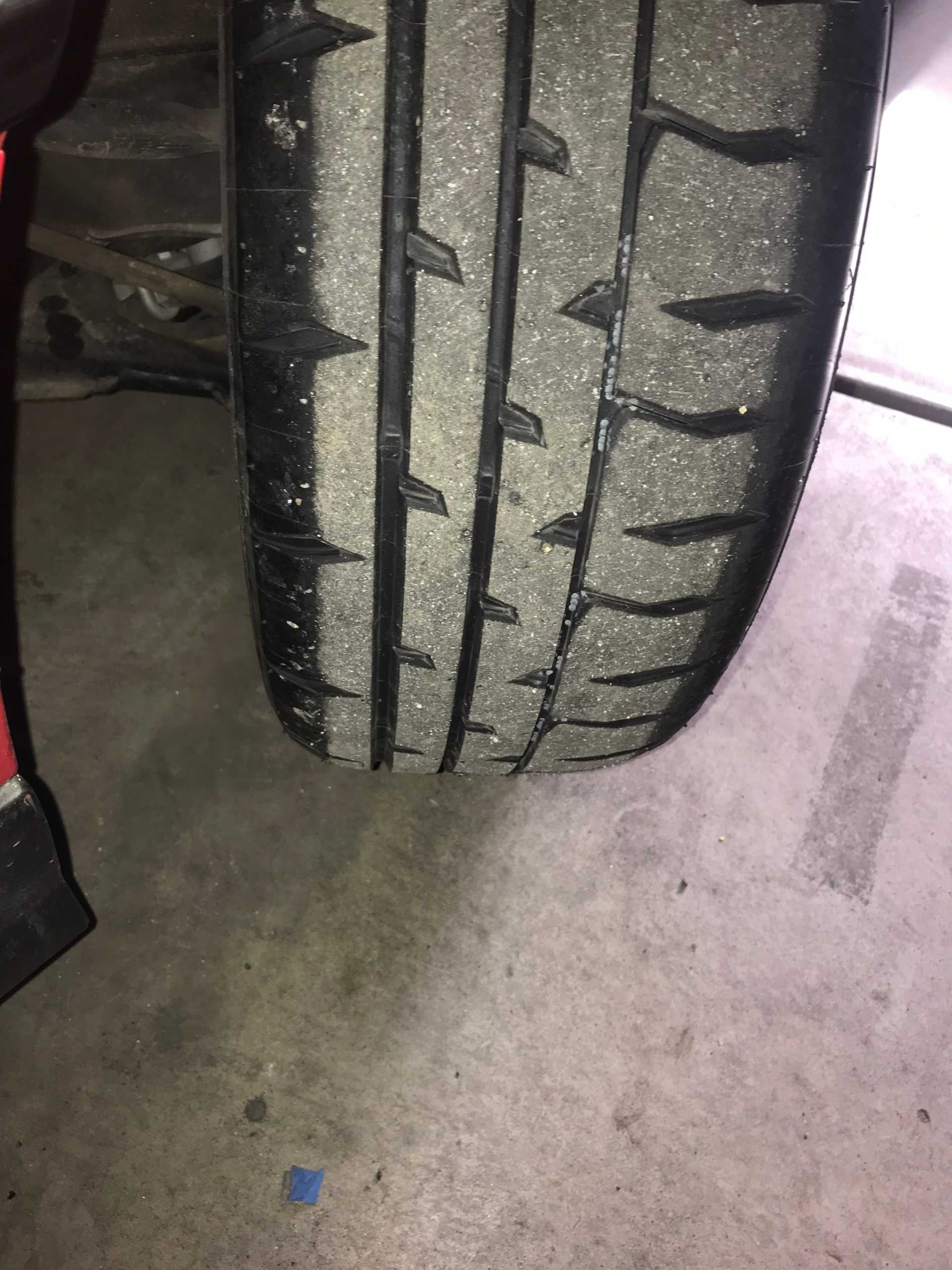
Also got a killer deal on Bridgestone RE-71RS tires. Tire Rack had closeout discount plus another discount if you use their credit card. End price was about $70 each. I bought two sets. Very sticky, Ok in moderate to light rain. Summer use only, very responsive, noise is fair. You feel all pebbles on the road and did I say very sticky.
[This message has been edited by MikesFirstFiero (edited 03-08-2025).]


 I was in Spokane on a work trip, and saw the Fiero's sitting out there. I walked over in my pilot uniform while waiting for a ride to the airport! Some sweet cars.