Glad to see another LFX conversion starting. Just a few considerations about using a 2013 drive train. I'm certain the earlier version of the engine electronics will be simpler to work with. It does not have the anti theft software that the 2018+ has. The engine will need a PCV modification to prevent clogging which is easy enough to do.
The transmission is first generation 6T70 and is known to be more fragile than the second gen starting in 2014. I looked up the MX0 tranny specs and see that it has a 2.44 final drive. Thats even lower than mine which is 2.77, your highway fuel economy will be outstanding. The manual shift operation on mine is all electronic with only two wires controlling it. It might be possible to change some parameters and add a simple switching cable with two resistors in it to make it work.
I've been fighting misfire at higher revs but now that is going away. It appears the primary cause is coking of the intake valves and GDI injectors that disrupts the fuel & air flow. All the GDI engines face this. My engine only has 60K miles on it and making it run right has been difficult. While I was able to run the Impala before pulling it apart I did not really ever get to run it to the redline where most of the misfire happens. I've done everything to avoid pulling the heads since it is in place in the Fiero. If I was starting over I would consider pulling the heads to have the valves cleaned and reseated and to remove the front cover to replace the timing chains. Those are known weak points of the engine.
But I didn't do that since it had no symptoms at mid revs and idle. So what to do? New plugs and coils made some difference. Then I did some hunting on the web and found a GDI intake valve cleaner product CRC GDI Intake Valve & Turbo Cleaner. Hard to find but not expensive at $16 per can. I got one a week ago and followed their instructions. It did make a definite improvement in the overall smoothness and high rev operation. They tell you to drive it every day after the treatment so that's what I'm doing now. After about 1K miles I'll do it again. I may also need to have the injectors cleaned by a local shop at $25 each but that will wait until I have the extra cash. If your engine has considerable mileage I'd make sure the intake valves & injectors are clean. I also have a catch can on the way to try to collect most of the blow-by from the PCV before it gets into the intake manifold. I will post when it arrives and I plumb it in.
[This message has been edited by MikesFirstFiero (edited 02-04-2022).]
I have very much enjoyed watching your swap progress.
I have been planning to LFX/6T70 swap mine for a few years now, and it looks like I will be able to start on it this summer.
Getting the LFX cruise control to work is something I have been trying to figure out ahead of time, as with a few other things I anticipate being a challenge.
Keep up the good work.
When you figure out the cruise control, let me know. I started with the same Impala you are using. I went with a Saab F40 manual transmission. Bolts up easily to the LFX using the stock Saab clutch.
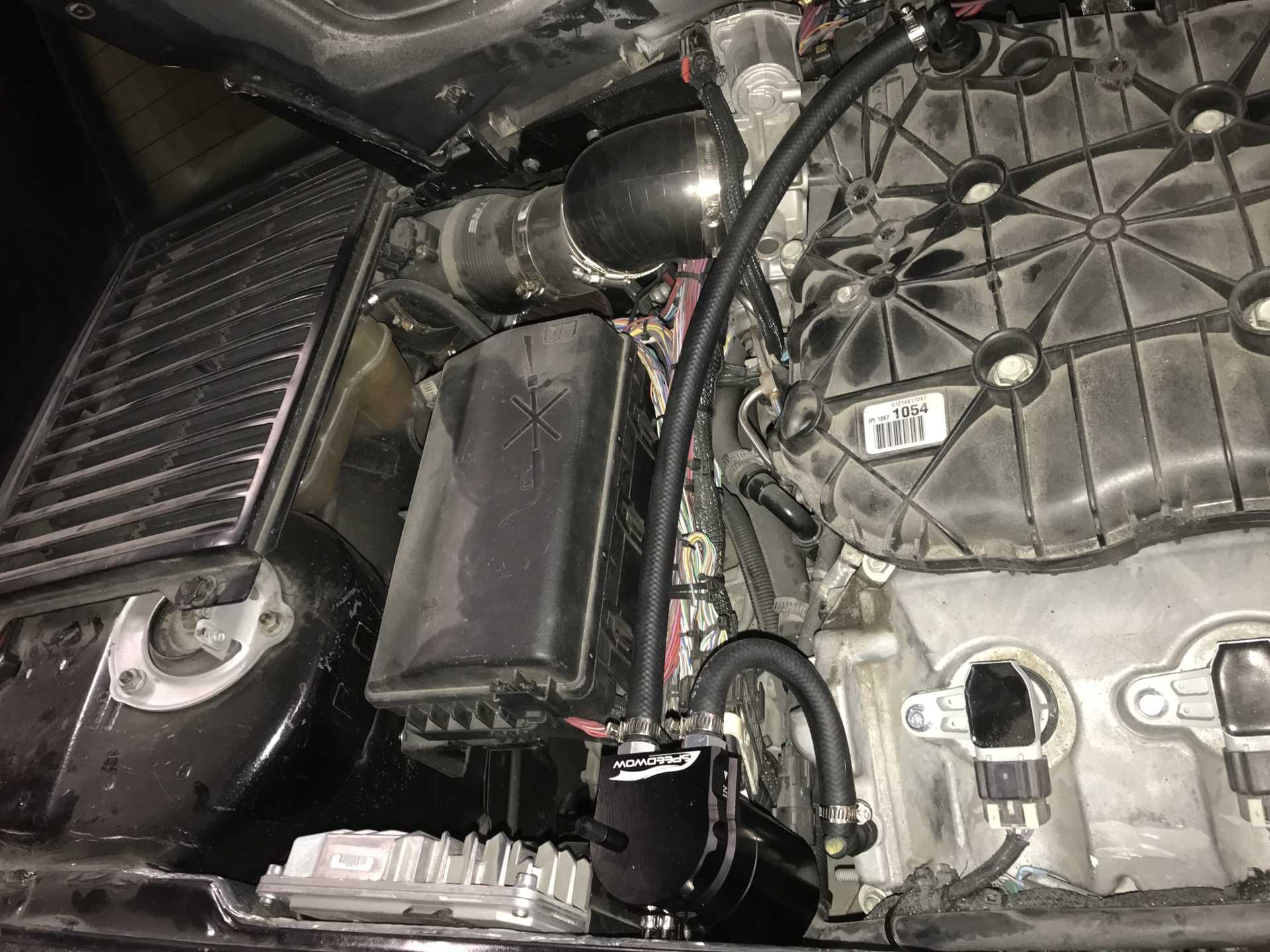
My oil catch can came in today and was simple to mount to the engine bay next to the ECU. The one I bought was $35 from Amazon and came with hose (with fabric cording), fittings, clamps and a mounting bracket. It is a "Speedwow" brand (who names this crap?). I bought it from the Amazon warehouse since someone returned it, saved me $5. Well built, anodized and everything fit together well. Only issue is the top mounting hole on the bracket is behind the can body and it's difficult to get a nut in there. But five minutes of messing with it got the screw started.
I'm sure this will make a difference to reduce the coking of the intake valves. After getting the car running I pulled the throttle body off to do some work near the firewall. Before I began running the engine the intake was cleaned and dry inside and out. With only about 100 miles of driving the IM interior had a nice thin coating from oil mist. I've checked the oil level and it has not gone down at all, there are no leaks and the exhaust has no oil smoke. I'll keep an eye on the level of fluid in the can and report how things turn out.
The can installed
[This message has been edited by MikesFirstFiero (edited 02-04-2022).]
I finally got around to looking at the steering shaft which is very loose. The free play at the wheel rim is almost an inch and this makes the car very difficult to drive at speed and on bumpy roads. Getting it out is simple, "just" crawl under the car and release the clamping bolt and "just" crawl into the foot well and loosen the other end and out it comes (if you can compress the slide coupling on the two halves).
Expecting the U-joints to be worn I ordered two new ones from Amazon, 1/2"DD to 3/4DD. They arrived and were nice quality stainless steel with no play at all. I expected the old ones on the shaft were the problem. Turns out the old ones were good. The primary cause was the sliding joint on the shaft uses nylon pads to allow the shaft to easily change length when installing it. That had compressed over time due to the forces of the manual steering. The second cause was the rubber vibration absorber allowed some movement too. Inspecting the bearings of the U-joints showed they were a bit sticky but still very tight. So the new U-joints went back to Amazon. A side note while these were nice units the end for connection to the steering column would not go on. The steering shaft DD has a bump on one side near the end so the shaft is polarized and can't be put on 180 out.
The solution was to lubricate the U-joints with Tri-Flow which freed them right up. If you don't know, Tri-Flow is similar to WD-40 but has banana oil and Teflon in it so it cuts old sticky grease and also lasts a long time. Then get out the welder and weld the slip joint and the U-Joint to the shaft end at the big end. Only problem is then the steering column needs to be loosened so the shaft can be reinserted sine it can't be compressed. Just more time under the dash and it popped right in. While under there I found my brake switch installation will need a mod too.
The brake switch is rotary and sits with the sensor at the limit when the pedal is not depressed. The ECU does not like that sometimes when starting since it thinks the pedal is not depressed enough and won't let the engine start. Only happens when there is no vacuum and the pedal is hard to press down. The body needs to be rotated a bit so the ECU is happy. That's a job for another day though.
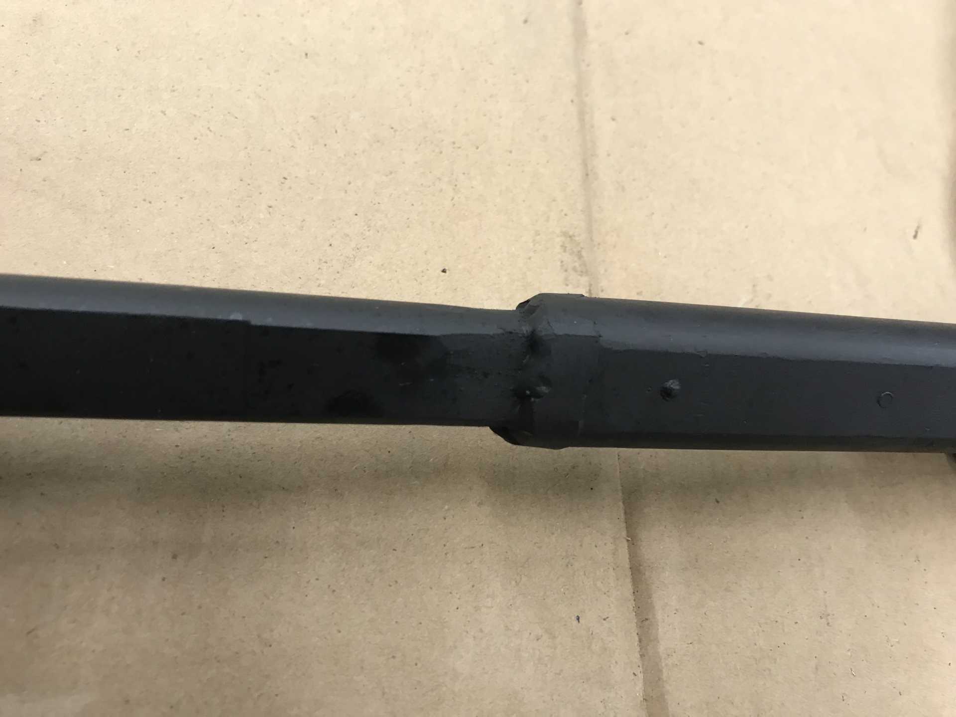
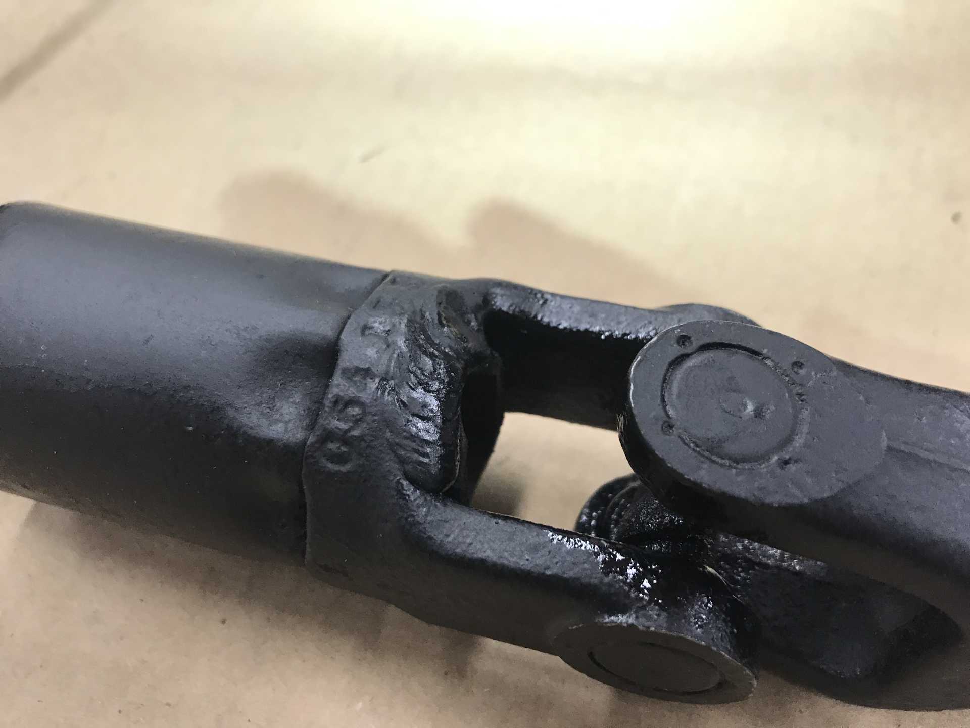
The shaft after welding and painting
The slip joint that caused most of the problem. It won't move any more now.
The rubber isolator also fixed
After all that a test drive now shows I have only about 1/8" play which makes me very happy.
[This message has been edited by MikesFirstFiero (edited 02-22-2022).]
That starting issue could be addressed by adding an electric vacuum pump to provide vacuum to the brakes under certain conditions my donor (2013 Impala) had this setup. To control the pump I used an adjustable vacuum operated switch and a relay.
Originally posted by MikesFirstFiero: The primary cause was the sliding joint on the shaft uses nylon pads to allow the shaft to easily change length when installing it. That had compressed over time due to the forces of the manual steering.
quote
Originally posted by MikesFirstFiero: The slip joint that caused most of the problem. It won't move any more now.
Yeah... the main reason for the telescoping action of that shaft isn't for installation. In case of a front-end crash, you don't want the impact to push the steering wheel into the driver. The telescopic section allows the steering rack to move backwards without ramming the steering wheel into the driver.
I would suggest starting over with another Fiero steering shaft.
If the plastic pads are destroyed on a replacement shaft, maybe you could restore it with polyurethane resin?
There are youtube how-to videos showing people pouring polyurethane to make stiffer engine/trans mounts. Maybe you could use a release agent on the DD shaft to make sure it slides on the polyurethane, with holes drilled into the female shaft so the polyurethane flows in and makes a positive lock.
I have the Aux Vacuum Pump from the Impala and may install it in the future to provide vacuum on startup. But it's one more thing to go wrong. This only happens when I've been messing with the brakes and bleeding them. When the brake switch is adjusted I think the problem will go away.
As far as the steering shaft you are correct that this was done for safety purposes. I've looked for a NOS shaft but I've not found any so far. The original design is pure crap with the high forces of the manual steering causing constant wear on this part. The Impala shaft uses three rows of sliding ball bearings to do the job properly but it's way too short to be adapted. Maybe something else might fit in there.
The slip joint that caused most of the problem. It won't move any more now.
THIS IS NOT SAFE, you NEED to get a new shaft ASAP. That is a slip joint designed to slide in on itself during a front end collision; with it now welded solid, the steering wheel will literally decapitate you in an accident.
Surely you can easily find one by posting in The Mall.
------------------ "Discord" Red 1988 GT under restoration!
Well calm down a bit. I agree that it is not as safe being welded as if it could collapse. But it is only one aspect of safety for the vehicle since it also lacks ABS, Air Bags, Traction Control, TPMS and the last 30 years of crash protection design of the current crop of cars. In the bigger picture I expect that in a crash my low to the ground car will submarine below the newer taller cars and trucks of today and being impaled by the steering column is the least of my worries.
The idea that cars are "safe" or "unsafe" is a matter of degree not an absolute. I'm writing as an engineer with years of experience in equipment with life safety conderns. Driving a small, light car without modern safety equipment and with a 300HP engine swap is far from the safest choice of those available. In fact I'm still considering adding ABS from the impala if I can find a way of adding wheel speed sensors. Thanks for your concern.
I gotta agree with your assessment. Besides, many of the "government imposed safety items" are generic. By that I mean they are required for all cars regardless of design. Some cars had long steering columns that could impale a person. Others positioned the steering wheel so close to the dash that impalement was not even possible, but government rules are government rules. Not worth it for a manufacturer to argue the point. Cheaper just to comply with unnecessary rules.
Well they can't really ignore any standard. look at what it cost VW with cheating on the Diesel emission testing. When all was said and done it cost them a lot of money and the cars did not run as well as before. My friend has a diesel Passat and did not let them convert it or buy it back since it cruises on flat ground getting 50+ MPG at 70. And it does not require DEF.
I'm thinking the corporate decision makers see the electric car as a way to get rid of a whole lot of regulations and mechanical complexity. The only really big problem for them is the Lithium batteries and what happens if they start to burn. The other problems like how long it runs, where to charge it and where the energy to do so will come from become Other Peoples Problems, not theirs.
I've read that the electricification of the US auto fleet will require a 50% increase in generated power, not all at one but still probably 10-15% per year as the new cars phase in. Care to guess where that will come from and who will pay for it? My thinking is if they try it with wind & solar it will be a miserable failure with prices zooming. Until fusion or something equally disruptive comes along the need for gas turbine, oil & coal fueled electric power generation will not go away. Lets see how Britain works out since they have banned the sale of petrol cars starting 2030.
I really don't care if you agree or disagree with my opinion, you are certainly welcome to your own. But there is little little people who live with the consequences of our leaders decisions can do about it unless the "new" solution is a true failure and it puts our well being in jeopardy.
[This message has been edited by MikesFirstFiero (edited 01-30-2023).]
THIS IS NOT SAFE, you NEED to get a new shaft ASAP. That is a slip joint designed to slide in on itself during a front end collision; with it now welded solid, the steering wheel will literally decapitate you in an accident.
Surely you can easily find one by posting in The Mall.
Correct. A collapsible steering column is an easy cheap passive safety measure and there's no excuse for eliminating it.
quote
Originally posted by MikesFirstFiero:
Well calm down a bit. I agree that it is not as safe being welded as if it could collapse. But it is only one aspect of safety for the vehicle since it also lacks ABS, Air Bags, Traction Control, TPMS and the last 30 years of crash protection design of the current crop of cars. In the bigger picture I expect that in a crash my low to the ground car will submarine below the newer taller cars and trucks of today and being impaled by the steering column is the least of my worries.
If you're an engineer, then you can look up the DATA on crash testing and figure out how a Fiero compares to modern cars... in the '80's is was top of the pyramid.
Any crash that moves the steering rack relative to your seat is going to force the steering column to go SOMEWHERE. If it can't collapse... maybe it goes straight for your chest and the steering wheel crushes your ribcage. Maybe the bottom u-joint kicks off to one side or the other and breaks your ankle or tibia. Maybe it goes down and pulls the dash down onto your knees, pinning you in the car.
Why make a bad crash worse by deleting easy cheap passive safety equipment?
quote
Originally posted by Daryl M:
I gotta agree with your assessment. Besides, many of the "government imposed safety items" are generic. By that I mean they are required for all cars regardless of design. Some cars had long steering columns that could impale a person. Others positioned the steering wheel so close to the dash that impalement was not even possible, but government rules are government rules. Not worth it for a manufacturer to argue the point. Cheaper just to comply with unnecessary rules.
A collapsible steering column is hardly the same as the 14th air bag that results in 0.0001% reduction in theoretical statistical fatalities if implemented in 10 million vehicles.
Collapsible steering columns were the result of observing what actually killed or injured people (or crash dummies) in actual collisions (or crash testing). Since they came into practice as early as they did, they're right up there with other "Duh" safety features like... tempered glass.
Go LOOK at what's out there. Steering linkage companies have nesting D-shaped tubing available for making telescoping steering shafts. If the guy building a '32 Ford has a collapsible steering column, you can too.
I'm thinking the corporate decision makers see the electric car as a way to get rid of a whole lot of regulations and mechanical complexity. The only really big problem for them is the Lithium batteries and what happens if they start to burn. The other problems like how long it runs, where to charge it and where the energy to do so will come from become Other Peoples Problems, not theirs.
You're thinking wrong. Auto makers are going electric because government regulators are telling them that governments will outlaw production of ICE powered cars. Nobody actually put any thought into this as forcing the entire fleet to be electric is stupid for a lot of reasons, and trying to make it happen that fast is stupid for even more reasons.
There are certainly use cases for electric cars and benefits for which they work better than ICE powered cars... and vice versa.
quote
Originally posted by MikesFirstFiero:
I've read that the electricification of the US auto fleet will require a 50% increase in generated power, not all at one but still probably 10-15% per year as the new cars phase in. Care to guess where that will come from and who will pay for it? My thinking is if they try it with wind & solar it will be a miserable failure with prices zooming. Until fusion or something equally disruptive comes along the need for gas turbine, oil & coal fueled electric power generation will not go away. Lets see how Britain works out since they have banned the sale of petrol cars starting 2030.
Yeah, there's a lot of stupidity behind the effort.
One thing we could do *NOW* without any pie-in-the-sky methods like fusion or grid level storage to make renewables work is nuclear... and yet the NRC makes it almost impossible to build new nuclear plants.
I spent about 8 years being trained, training, and operating nuclear reactors, this will be my only comment on the subject, as I feel I am adequately qualified to make a comment, unless the OP wants to continue past this, I won't make another comment on the subject.
quote
Originally posted by Will: One thing we could do *NOW* without any pie-in-the-sky methods like fusion or grid level storage to make renewables work is nuclear... and yet the NRC makes it almost impossible to build new nuclear plants.
This is largely because oil, coal, and gas industries have heavily lobbied and run widespread fearmongering campaigns to convince the public that every nuclear reactor is hiroshima, nagasaki, or worse, when even military nuclear reactors have nowhere near the power density required to create a *NUCLEAR*(IE prompt criticality) explosion. Fun fact, a typical coal fired power plant releases more radionuclides to the environment, over larger areas, than nuclear plants do, this is because the coal contains radionuclides, and when burned, these radionuclides are released through the smokestacks of the plant, whereas any of the radionuclides in a nuclear plant are contained by the cladding of the "fuel" once expended, the fuel can be contained to a small cask, which prevents the release to the surroundings. all without any CO2 emmisions. the spent fuel(which takes up a very small amount of space) , can be used as fuel in different types of reactors, although, regulatory bodies in the United States (The NRC among others)do not currently allow this large scale yet, hopefully that will change soon enough.
------------------ "I am not what you so glibly call to be a civilized man. I have broken with society for reasons which I alone am able to appreciate. I am therefore not subject to it's stupid laws, and I ask you to never allude to them in my presence again."
One last note about energy. Turns out that I have a Bachelor's in Nuclear Engineering (U of Fla 1969) and agree completely about the hysteria that has been generated about Nuclear generated power. Right now Europe is figuring out the hard way that shutting off something that has worked (reactors), trying to depend on wind and solar and buying natural gas from your not-very-friendly Eastern neighbor are all very bad ideas. Now back to cars.
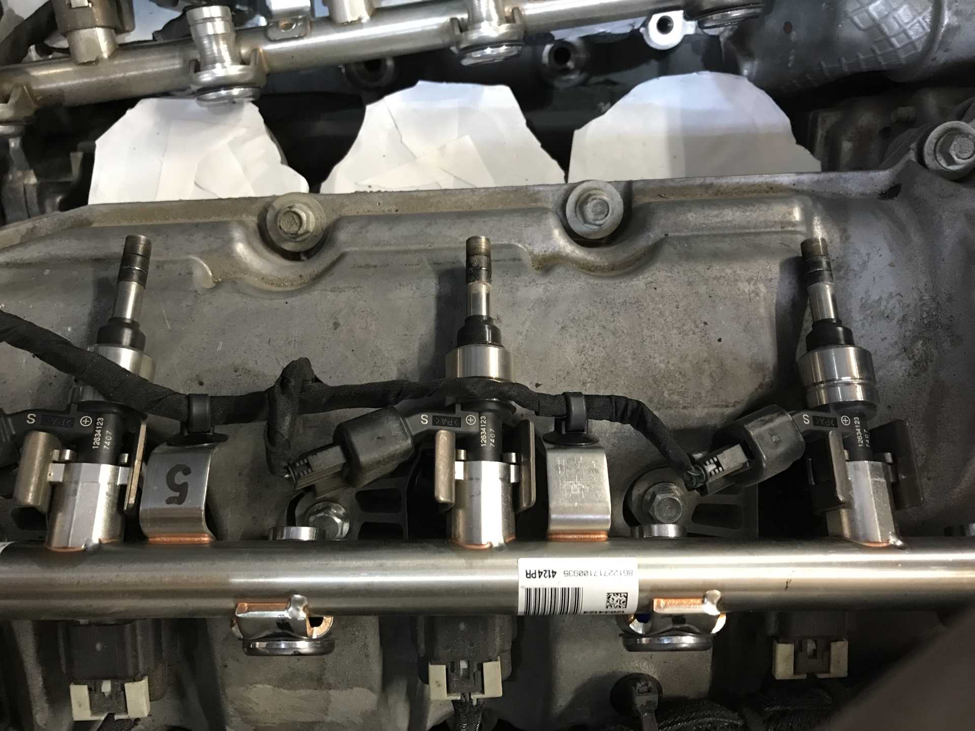
Since I've tried just about else everything that could cause misfire I finally pulled out the fuel injectors and had them cleaned. Removing the injector and fuel rails on the LFX is a bit fiddly but not too difficult. Off comes the intake manifold, IM gasket and a sound isolating pad. Next the high pressure line from the HP fuel pump to the rails is removed. Then each rail that is held on by 4 bolts are exposed. You must remove the bolts from both rails to get clearance and then remove the aft rail first. The shop manual shows using a special tool that assumes it is difficult to remove. On this car it simply pulled out from the head by hand. Getting it out of the car when loose took a couple of minutes wiggling it out. There is very little room for it to be removed. Once the rear rail is out the forward rail is removed the same way. Be sure to take photos of how it looks since they assemble in only one configuration.
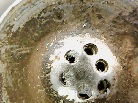
Once on the bench the injectors are held to the fuel rail by substantial C shaped retainers that must be carefully pried open and removed from the rail. A couple of screw drivers as pry bars and tapping with a small hammer removed the retainers without damage. The injectors were still held in place by the O-rings on top and popped out with some twisting and pulling. Visual inspection of the injectors shows each has six very small jet openings. Most of them had some white material deposited on the jets. One injector had two jets completely blocked and 1/2 of the third jet half blocked. Off they went to Mr.Injector in Coeur D'Alene, ID for cleaning. Bill Johnson runs this shop in CDA and has customers from across the entire country. He inspects, tests, cleans and re-tests all of them. He then provides a written report of the before and after condition. I highly reccommend his service at www.mrinjector.us. He can do port and GDI (Gasoline Direct Injection) injectors but no diesel.
One rail has a pressure sensor that measures up to 2000psi. Wow that's a lot .
I finally have updated the photos that Bill took. This injector is really bad.
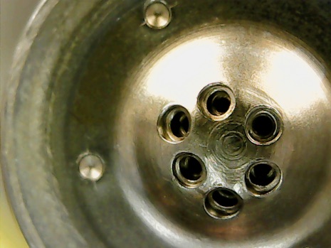
Nice & clean after Bill's work. These have now 63K miles on them.
Each jet on the injector is about 0.003-0.005" diameter and is shaped in three steps for correct atomization. With the crud on the injectors before cleaning it is obvious the fuel flow was restricted and the spray pattern disturbed. Since these are GDI parts it is critical the jets be clean. According to his tests the flow rates should have been 48 lb/hr but actually were between 47 to 43 and the mist pattern was very disrupted. I've read the engine runs in two modes, at low power it runs a mixture of about 65:1, put your foot into it and the mixture goes to about 24:1. This is possible since the injection is under 1,900PSI, opens for about 1 ms, is precisely timed and the fuel is actually delivered as a fog so almost all of it is burned.
The next step was reinstalling the injectors to the rails. There is a tool available for these injectors to snap the retaining clips in place. Only problem is it lists for $280. Ouch, so forget that! Bill suggested using a big slip-joint plier. That did work and only took about 3 minutes each to get them to snap into position. GM says to not re-use theclips, I did anyway with no adverse effects. GM also says to replace the metal pipe from the HP fuel pump to the rails, which I didn't do either. The clips are about $5 each and the pipe is $80. Per GM if you remove an injector you must rebuild or replace it. Expensive stuff on these new engines. Putting them back in is the reverse of removal. Once fiddled into position the tips of the injectors engage the holes in the head, then you use the mounting bolts to push them in to position. Next remove the mounting bolts, install the second rail and tighten them too. Then re-install the bolts for the first rail. This part of the engine was designed with very little clearances to work on so you must follow the shop manual sequence. The rest is to button up everything else removed.
While the IM was removed I spent a few hours finishing up the looming of the ECU and fuse box cables. It looks much better now. I also found the fuse box bracket I fabbed was too flexible and was bending a bit. Iwas worried it might crack and cause a problem so I added a triangular brace to prevent it from flexing.
The moment of truth... It cranked up with no problems or leaks and settled down to a good idle in a few seconds. So far so good. I took it on the road and it was smoother at all throttle positions. Full throttle zipped up to the redline with zero misfire in 1, 2 and 3 (that's like 90MPH). I also noticed the real-time fuel economy readout used to show no more than 43MPG at cruise of about 50MPH, now it showed a peak of 51MPG. I'll see if that proves to be true with the next couple of tanks of fuel. I could not be happier with the results. I'd suggest that if you have a GDI engine with substantial mileage check the injectors visually. You will need a good magnifying glass to see the jets since they are really small. If there are any deposits visible get them cleaned by someone with the right equipment and chemicals. I'll keep an eye on the reused pipe and the top of the engine for any fuel leaks over the next few weeks just in case too.
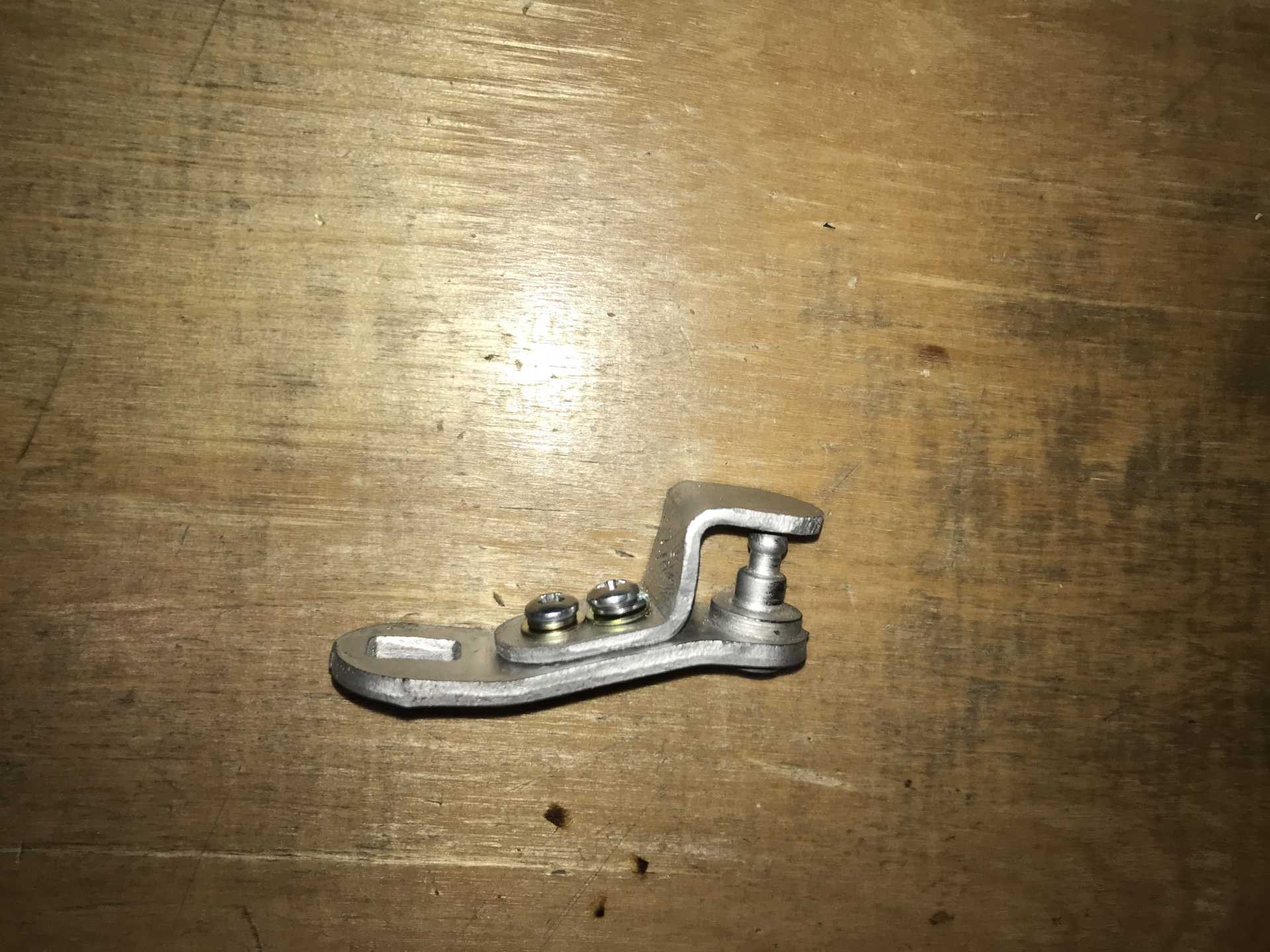
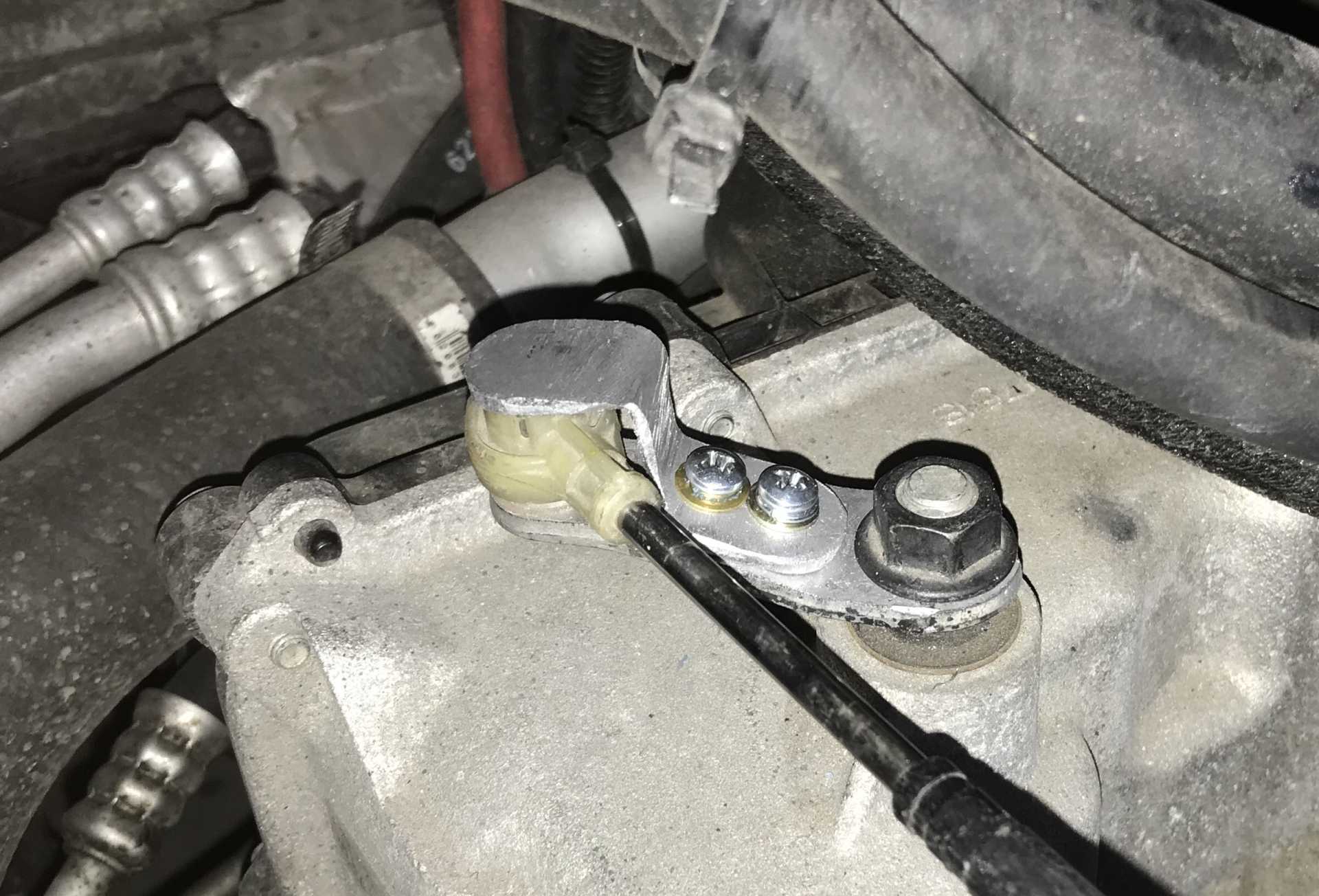
While waiting on the injectors to arrive I solved an annoying problem that has happened twice. The shifter cable has popped off of the arm at the transmission end, psobably since the cable end retainer is a bit too large. The arm is perfect otherwise and matches the throw of the original Fiero shifter. So I whipped up a retainer that screws on to the arm and keeps the cable end in place.
It did need a bit of trimming to fit when the transmission in Manual.
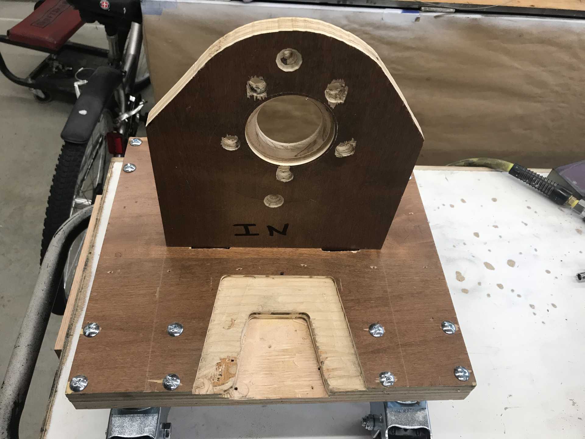
Finally got around to making a wheel replacement stand to allow access to the suspension adjustments while the car has all four corners under full load. It took some plywood and cutting to get everything to clear the front lower arm and the rear trailing link Finally I was able to reset the front and rear camber and toe since I noticed my rear tires were wearing on the inner edge. Popped the wheel back on and adjusted the toe and that's another job complete.
These are the final configuration with cutouts to avoid the lower ball joint and arm in front and the trailing arm at the rear trunnion. The base is 2x3/4" plywood cut to clear the casters. I used Home Depot 3" ones with wheel locks, same as used to support the engine and cradle earlier. The wheel attachment is a single piece of plywood with the 5x100 PCD drilled and a relief on the back side to cleat the hub.
Here it is in use on the front.
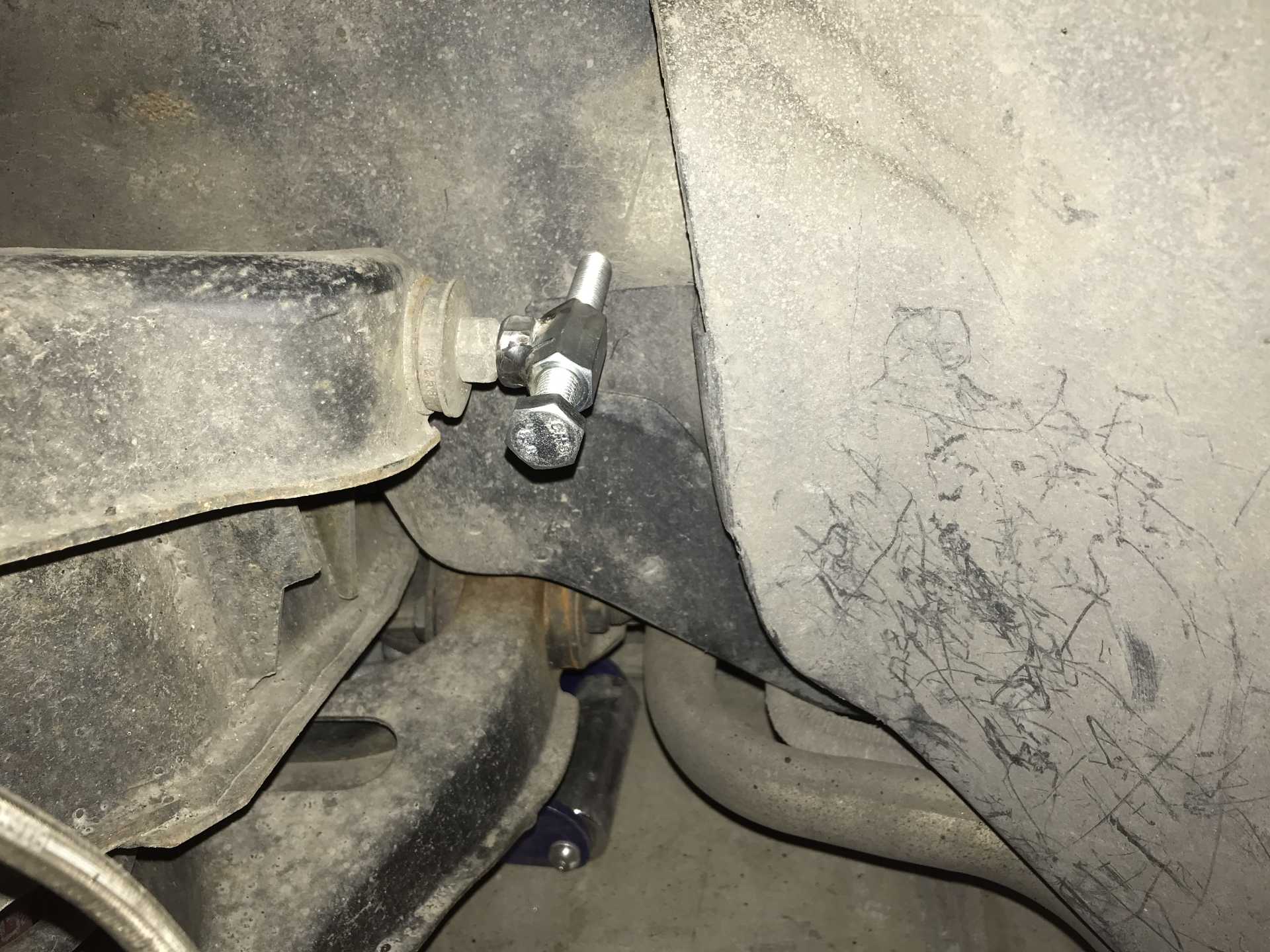
And I made up a pair of upper arm adjuster tools out of 12mm bolts and coupling nuts. These are really essential to make adjustments under load. There was a commercial tool available but this cost only $15 to make.
Here is one of them in use before I made up the foot. The foot is needed to keep the tool in position since it wants to walk when being tightened.
And then something unexpected happens. Driving over to Spokane the other day I noticed what seemed to be an imbalanced tire. I stopped and checked for a low tire and loose lug nuts, nope those were OK. Then I noticed that it increased when I applied torque. This is starting to seem serious. The more torque the worse the vibration even for engine braking too. That made me sure it was something wrong with the rear left corner. I dug into it and found the left hand tailpipe hanger had broken loose and the only thing holding the entire muffler on was the pipe from the engine. The mufflers were flopping around and that seemed to be a likely cause of vibration. Ok so I fixed that using one of the Impala muffler shock mounts to provide a bit of give. Buying that wrecked Impala has provided all kinds of parts for reuse or repurpose. Test drove it and the rattling was gone. The vibration wasn't.
Tailpipe hanger improvement
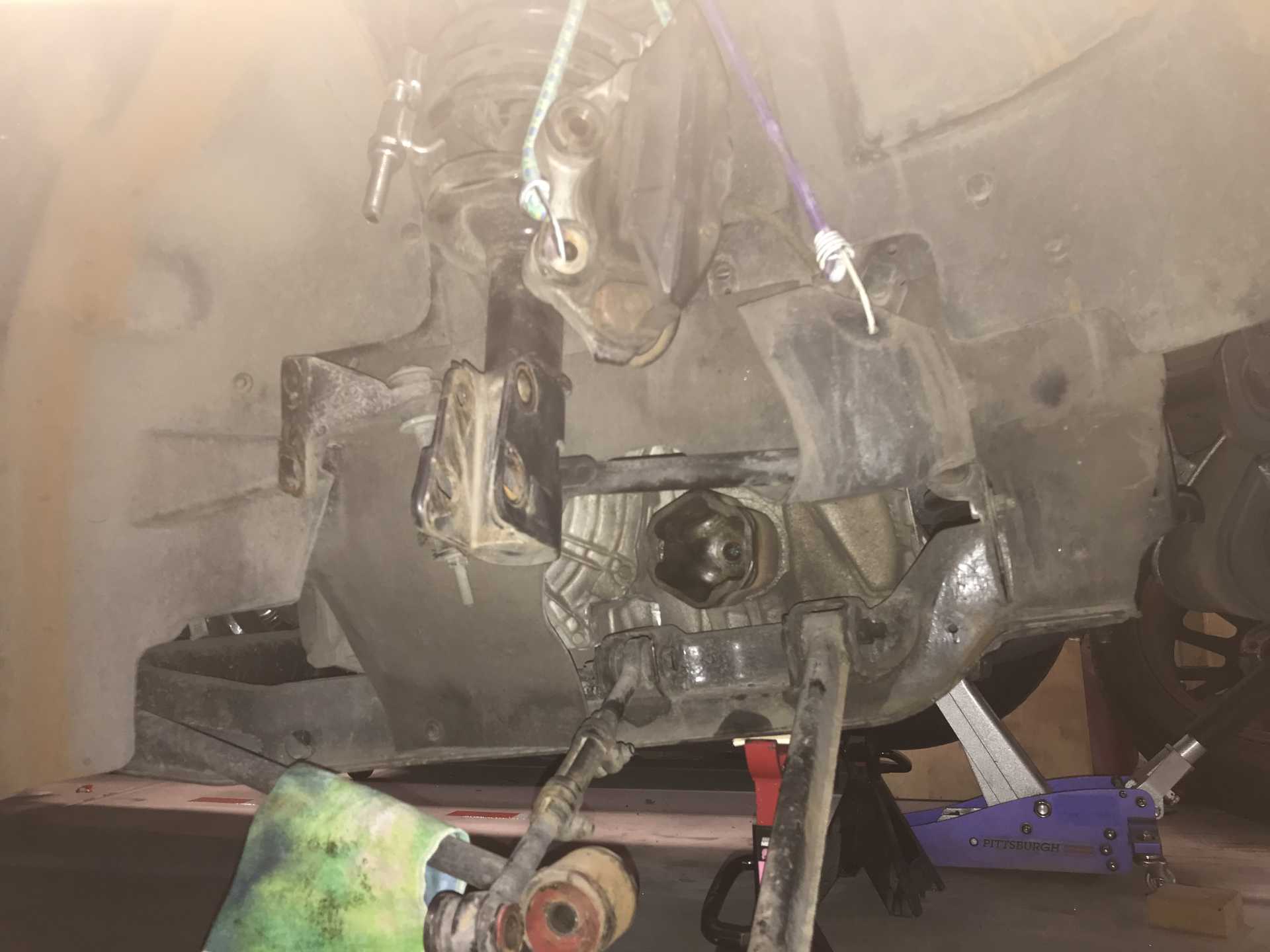
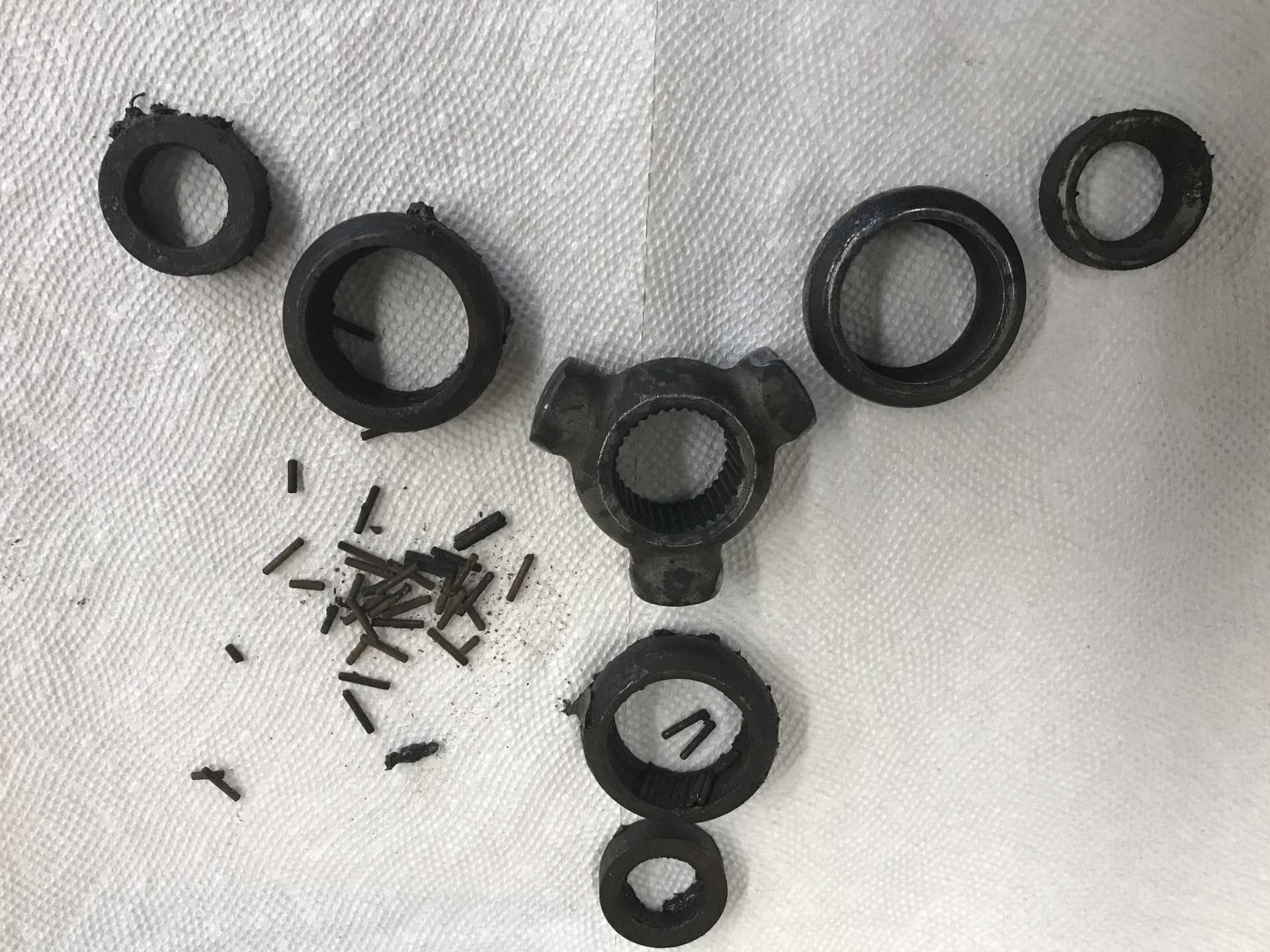
Back under the car one more time to disassemble the LR suspension. Once I got the strut springs compressed and the trunnion loosened it was obvious that the inner joint had failed. It was caused by the boot not being fitted correctly allowing winter dirt, water and crud to destroy the tripode joint. I was completely trashed and needed replacement. I should have put 2 & 2 together and noticed that when I jacked up the car I had some rusty water on the floor. Thought the water came from the cradle which has some holes on the bottom. Nope, it came from the not-tight-enough boot fastened to the axle.
Not too difficult to remove the axle shaft.
Water and Tripode Joints do not mix. The needle bearings disintigrated and everything fell apart. No idea how long this has been going on but I suspect quite a while.
I went on the hunt for a replacement joint. GM lists an inner joint kit, but it's made from hen's teeth, nobody has any in stock. Auto Zone & O'Reilly's don't even list it. Rock Auto lists it but it's not available. The only solution is to buy a complete axle and strip off the boot (I'm going to use the factory boot this time), tripode unit and stub axle that plugs into the transmission. If I ever need to make another axle I at least will have the raw materials. Maybe I can sell the outer CV joint too. With shipping $137, due next week. Once that side is done I'll check the other side by loosening the boot and seeing what the grease looks like. It seems tight but...
To follow up on the injectors and pipe that was re-used, these show no signs of leaking or becoming loose. I guess reusing the pipe may be ok to do.
And the drive shaft arrived today, wasn't expected until Tuesday. I was pleasntly surprised with the cost of the OEM Delco part from RockAuto.com and the quick shipping and delivery. When it arrived I cut off the retaining bands of the inner joint and pulled the cup from the axle. Then the tripode retaining clip and apart it came. Since it was loaded with grease I didn't need to add any. The boot went on the Fiero/Impala shaft first and then the tripode and clip and finally the bands. Putting it in was a breeze but there is one step that I learned about when removing the original Impala cup from the transmission. You need to drain almost a gallon of ATF before removing the axle cup otherwise you will have almost a gallon to clean up. Took a while to re-connect everything and reset the camber to -1.0 degree. Finally the ATF was returned to the transmission since it only has 1.5K miles on it. A quick run around the block showed that the problem is solved. I'll check the bands every day for a couple of weeks to make sure they don't come loose. I don't want to do this again on ther same side. However I will replace the right side inner boot with the OEM part next time I feel up to spending two days under the car.
[This message has been edited by MikesFirstFiero (edited 01-30-2023).]
Just to let y'all know that this post isn't dead yet. After getting the axle repaired I just drove it and did very little until I had the cash to begin the paint job. I'll be posting that in a week or so. Well Maybe a bit longer...
[This message has been edited by MikesFirstFiero (edited 01-30-2023).]
Sorry for the long delay that week or so turned into a few months. My back had been bothering me more and more in the last year so it was time to have a back surgery to fix it. That meant getting all the household winter prep work done two months early plus attending to the HoneyDo list. The surgery was in late September went well with no complications and recovery wasn’t nearly as bad as I expected. If you suffer from sciatic pain in your legs this could really help. It's now been 4 months since the surgery, my back & leg pains have disappeared and I'm able to do more physical things without pain. Got to drive the Fiero five weeks after surgery so things have been looking up. After the surgery I wasn’t allowed to do much of anything so no car work. Couldn't lift anything over 15 pounds and had to wear a back brace to prevent spinal movement.
Since the installation I've driven about 3,000 miles so far. No new problems since the rear axle repair. Drove it over to Missoula, Montana (about 170 miles) at 85 mph and got 25 MPG. Needs a wheel re-alignment since it is a bit squirrely at speed. I’ve never checked the rear so I guess I should too. I think it needs some toe-in. Still have high RPM misfire, I've rechecked the injectors, replaced the injector connectors, confirmed fuel pressure and checked out all the ignition wiring. Guess I'll need to have an LFX guru look at it.
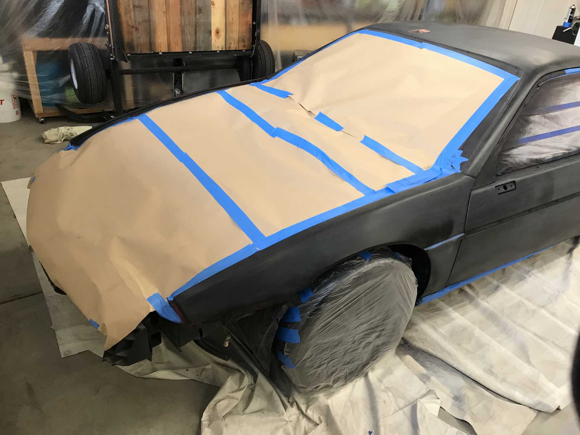
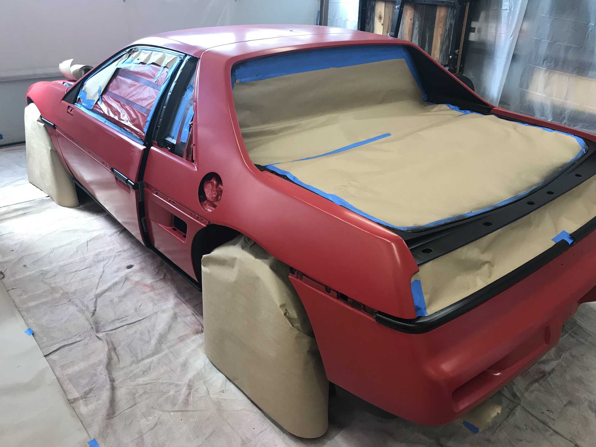
Back in April of 2022 I started getting serious about the body work and repainting the car. I decided to keep the original Bright Red GM color since I thought that would be simpler. I decided to not install the GT door trim, even though it would look better. I also like the look of some of the side scoop panels that are out there, but that was not in budget so I decided to keep the stock body and paint below the crease in the door in black including the chin lip on the nose and the lower part of the rear fenders & bumper. I got the idea of red over black from a Ferrari race car of a few years back. It unifies the lower part of the car all being black and would not be too expensive to add the second color. I’d found that a good qualityblack lacquer spray can will work and then apply clear coat over gives good results.
I decided to use the clear coat process instead of a single coat type of paint. That was a good and bad decision, as was the choice of painting it red. I used PPG Omni, a mid-grade paint not excessivly expensive but not cheap at About $100/quart or $270 per gallon - thats times two for base and clear. I’ve painted a few cars in the past with lacquer so I thought I'd give it a try. I did get a quote from a body shop of $10,000 so I'll do it myself. The paints of today are really different from lacquer. Most paints consist of a primer, sealer, base (color) and finally a clear coat. Primer bonds the surface of the original paint or plastic and to the following paint layers. It will cover up some minor surface defects when sanded. Primer comes in both solvent and epoxy (two part) types. For doing it in sections I used a good quality primer rattle can SEM and Dupli-Color are good they are solvent paints. Sealer is not as porous as primer and promotes adhesion to the base coat. Next is the base color which needed several coats, it was a solvent paint. The color layer is fairly soft so it needs the clear coat which is an epoxy paint that hardens, not dries, and is very durable.
The process I used was to sand down to the car’s original color coat since much of the original clear was flaking. In retrospect the door and side panels did not need this since the clear was in good condition. I also found the car had been in a minor collision with the LF fender repaired and repainted. I discovered this collision also did damage to the front of the car, more on that later. Problem #1 was the sanding with a Double-Action (Oscillating) 5” sander. It must be held flat against the body or you will get shallow dips in the body that are invisible until the glossy paint is applied later. I admit I didn’t understand this so my body is not as flat as it should be. But I’m not going to redo it since It’s a daily driver, not a garage queen show car.
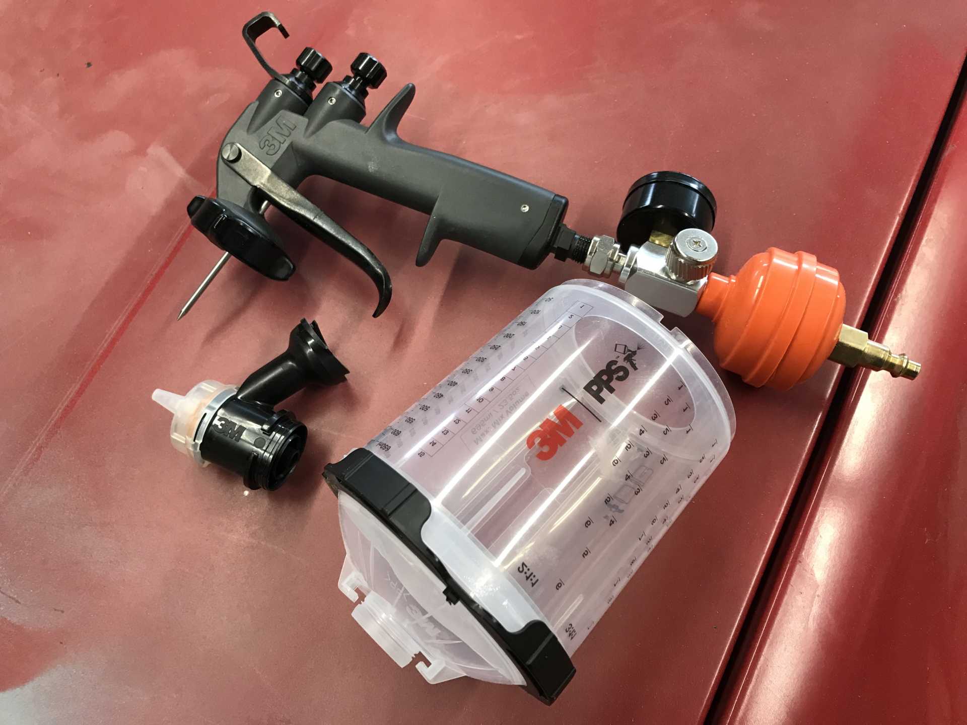
My old spray gun was a Harbor Freight $50 two pack (one small, one larger) but they are a pain to clean properly and do not atomize well enough for auto finishing. So I sprung for a 3M Performance Spray Gun. This comes with three sizes of nozzles, a cup with throw-away liners and a pressure gauge. What’s nice is the nozzles are easily replaced of clogged and cost $8 each so screwing one up is no big deal. The paint cups use the PPS-2 quick disconnect system which allows paint to be stored in the cup with a liner and sealed if you need to keep it. Cleaning the gun means only cleaning the nozzle with a spray gun cleaner which is super convenient. The gun has a fine atomization and a wide fan. Bad news is it costs $400. Could you do this with a $200 Harbor Freight gun? Probably, since the clear flows well and covers a lot of minor base imperfections. The big “but” is the cleaning of the gun. Since the clear is an epoxy the gun must be completely well cleaned within 2-3 hours of mixing the paint or it will harden and ruin the gun. With the 3M gun forgetting to clean in time costs you a $8 nozzle. Also the 3M gun will spray upside down since the paint cup liner is flexible and is not vented. And the paint filter is contained in the lid of the cup & can be cleaned for reuse.
Very light weight, Easy to clean, great fan, fine atomization
When you clean it only the black nozzle needs cleaning (and wipe off the needle too)
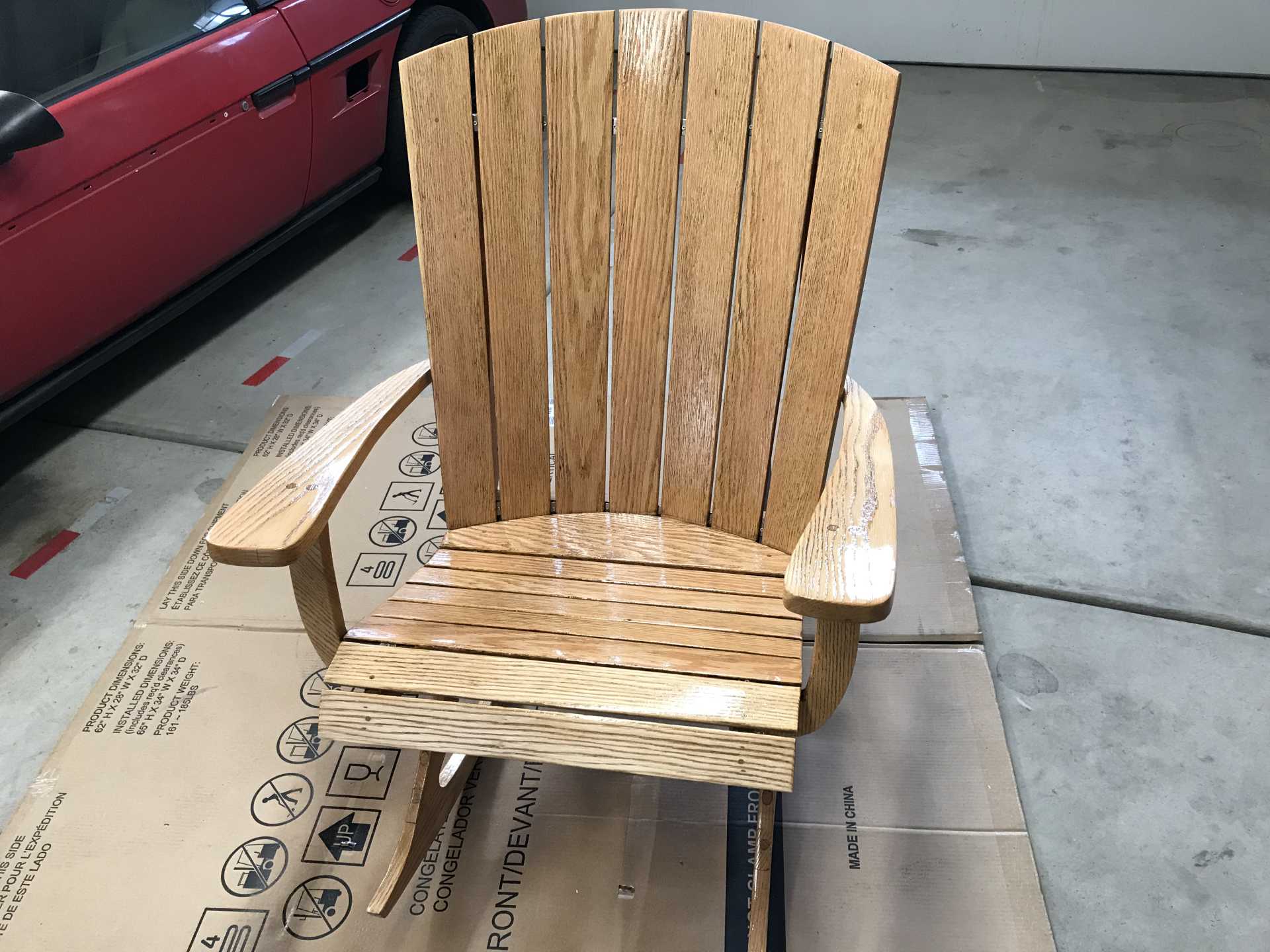
Another thing about the modern paints, for solvent paints (some primers and base coats) the overspray dries almost immediately so if it lands on anything in your painting area it will dust or blow off easily. Clear and epoxy primers are different. The overspray stays liquid for 2-3 hours from mixing and will stick to anything it lands on. And it’s a ***** to clean off of the anything it landed on. I first repainted chairs I made a couple of years ago with clear since the ureathane from Home Depot on them had yellowed. The chair sat outside for a couple of years and was becoming a mess. I sanded them to bare wood and shot some clear on them. I did not think to cover the storage racks in the garage. I just plunked the chairs down and sprayed. Almost everything exposed to the clear coat overspray now has a rough-feeling dust coat of the clear on it. Yup, got on the car too which came off easily with more sanding. But the chair turned out great. It was outside this winter to see how the clear holds up. After a warm January we are now back into our second winter.
Nice & shiny now
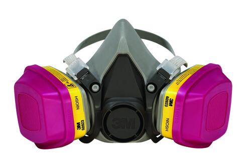
A warning about working with two-part epoxy paints. You must always wear a P100 face mask and cover as much skin as possible when using these products. The clear coat and epoxy primers are real health risks since the overspray will be inhaled as you work and will remain as a fluid in your lungs until it hardens hours later. Once it hardens it seems stuck to anything it landed on. It’s not like lacquer solvent paints where the overspray dries almost instantly and is a dust if you should breath some in. While that’s not good it’s not as nearly as bad as the epoxy products. A 3M P100 mask costs about $60 at Ace Hardware amd removes 99.5% of contaminates, including organic solvent vapors. Cheap protection for your one set of lungs. Some people recommend a positive air flow full coverage mask when using these products.
The filters are replaceable and cost about $24
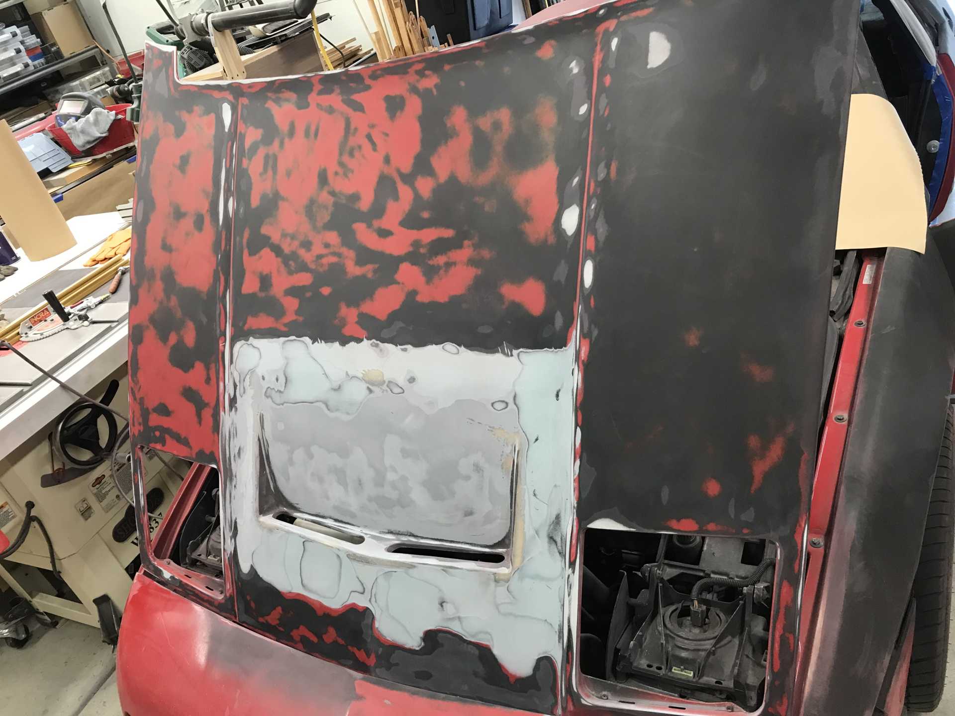
Before I painted the car I did make a test panel from the hood vent cutout of different types of surface preparation. How would the new paint apply over (left to right in photos) Old clear, Old base and clear and Original paint down to the bare body. The black strip at the bottom was to see how the trim black paint covered the old paint and would it survive having new clear over it. The second photo is the panel with a double coat of base red and then clear. As you can see the coverage by the red is poor but the clear shines well without any buffing or sanding - more on sanding & buffing clear later. Also notice the original hood was also re-primed and repainted following the accident I uncovered since it has two layers of red.
Sanded test panel with different amounts of sanding.
I applied one double coat of red and then one coat of clear. Red coverage is poor. Clear makes anything shine.
Primer does help get rid of the obvious imperfections but it has it’s limits. I used black primer since it was the car’s original primer and it seemed the right thing to do. You can expect to do lots of repriming and sanding, the more sanding and prep work you do the better the eventual finish. As far as sanding goes I’ve found the best solution is to use a high grade wet-dry paper and wet sand everything. The paper will last much longer and you will get more consistant results. I spend many hours sanding this body. You will also need a sanding block to give even pressure over the panels so the high spots are worn down without digging into the low spots. Between sanding & repriming, dust a bit of primer on the surface. When you start sanding this will show you where the high and low spots are. After spraying the final primer the next step is to prep sand the primer with 800-1000 grit paper gently to promote adhesion of the color layers. I skipped the surfacer layer since the primer I used seemed to be hard and not very porous. Then the surface needs to be degreased, cleaned and dusted so there is nothing on it. With the paint I used the color base does not need to sanded if you apply the clear within 24 hours.
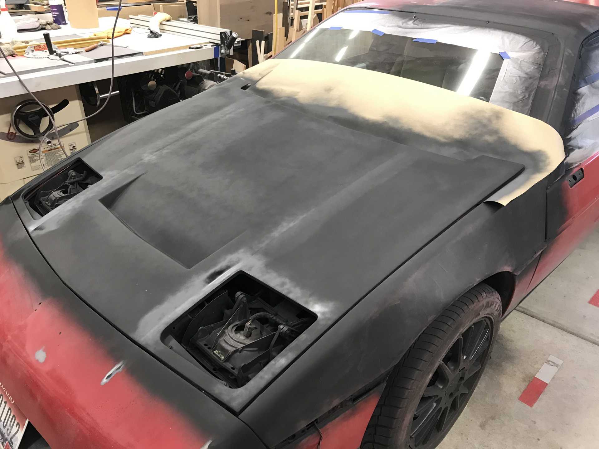
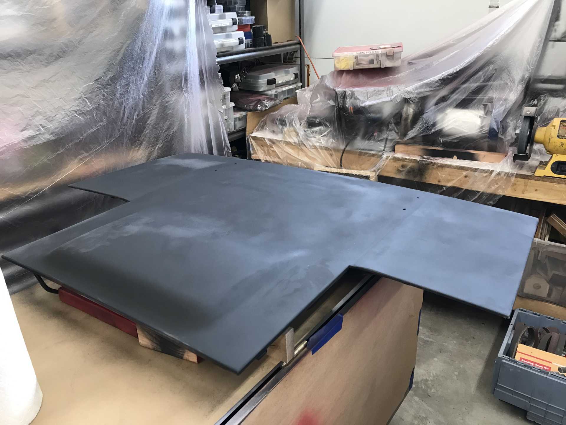
Hood before priming. Those splotches of primer/paint will show thru the paint as I learned. Smooth everything since the primer does not show these imperfections. Be prepared to do more prep work after putting the first shiny color coat on.
Hood after priming. You can't see many defects with only primer. They are there hiding in plain sight.
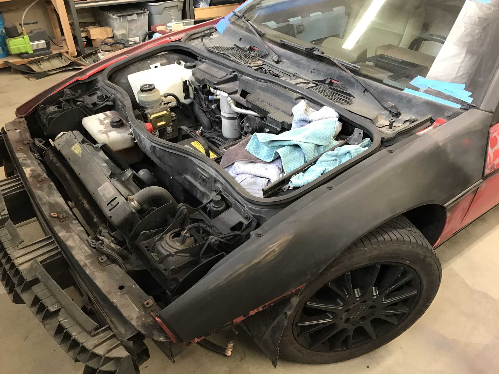
The front end damage can be seen by the warped A/C condenser. it was bent by the upper cross member being pushed into it. The member had been straightened but not correctly so the strip that mounts the bumper was not where it should have been, off by 3/8". Took a fair amount of pulling and hammering to get the cross member right. The LF fender was also damaged and repaired by others. It needed only a little reworking.
Finally after too many hours the primer is mostly done.
View from the front
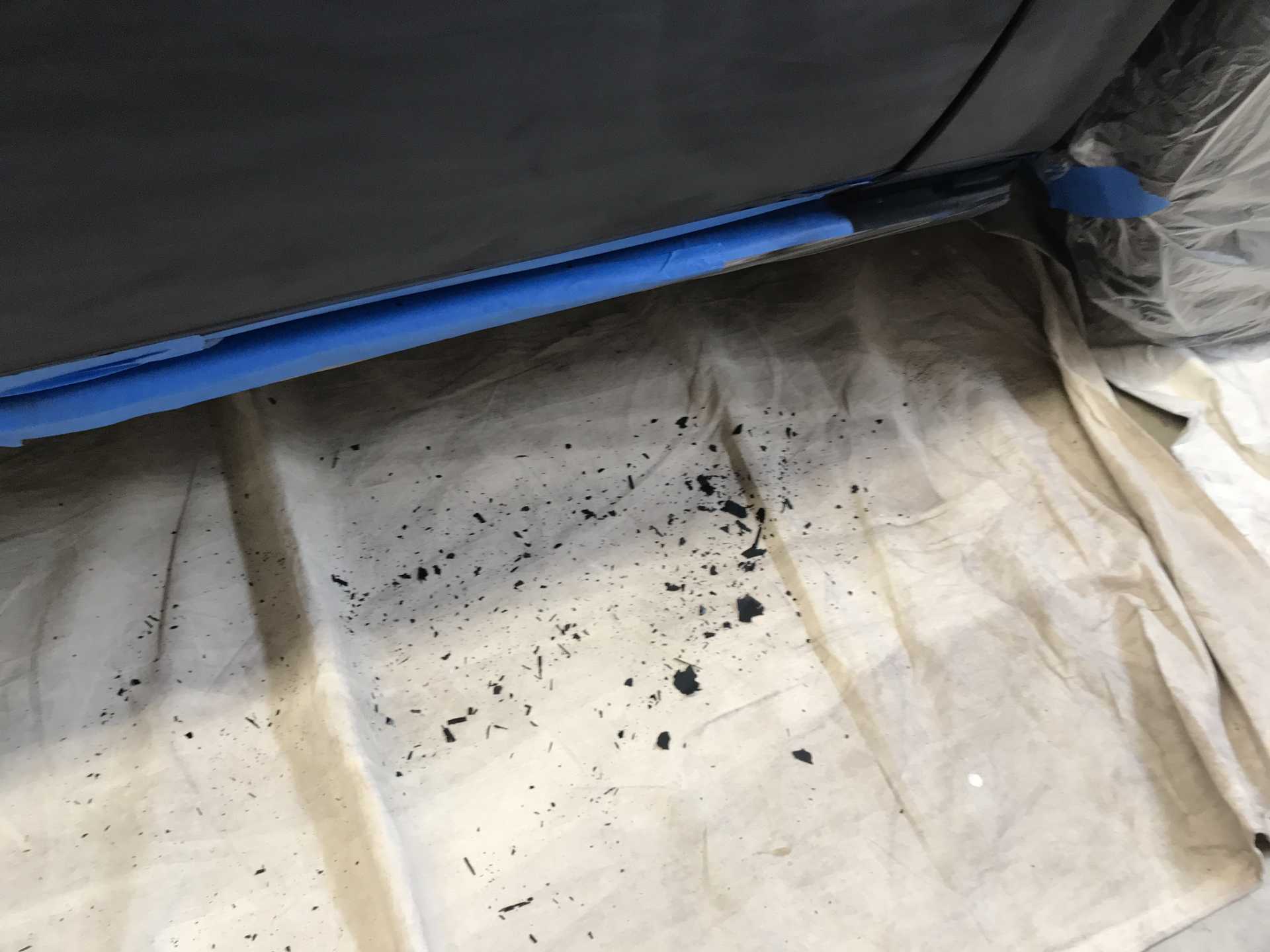
Problem #2 was the plastic sheeting I used for masking. I started painting with the wing by covering a work bench with plastic that I bought for masking. I did the priming then sanded and cleaned up the work area. Then I painted the color only to find the primer on the plastic sheet lifted into flakes and deposited itself onto the color. Crap. After every layer of paint the plastic sheeting needs to be replaced or use paper that will absorb the paint overspray. There may be some plastic sheeting that will adhere to the overspray but I would check this very carefully.
Photos of paint flakes off of the plastic sheeting. This photo is of the rocker panel. That paint fell off the plastic sheeting as it was removed.
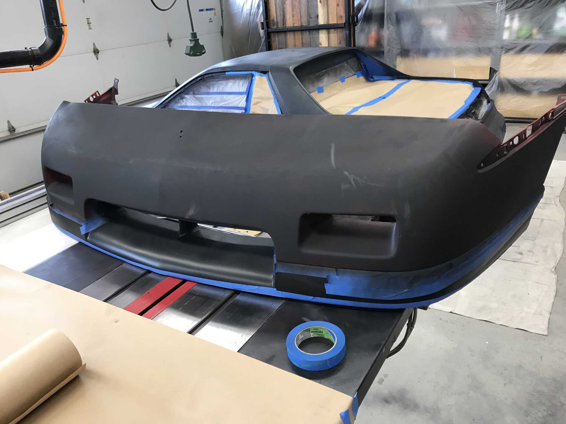
I removed the front bumper, hood and trunk lid to paint separately. It was seemed simpler to prep and paint these off the car. The hood took some time to get the hood vent joints to look OK but came out well. The trunk needed some glazing putty to fill in some gouges I made with the sander. Thw front bumper from a GT took some work and needed some heating with a hot air gun to eliminate ripples and sags from 30 years of gravity. But it looked good when complete. I then discovered the front of the frame was damaged in the collision. Not very badly but enough to mis-align the nose upper attachment rail and do light damage to the A/C evaporator.Getting the frame pulled out took some time but the nose-to-hood & fenders alignment is better. Then I mounted the nose and in installing it the clear coat already applied developed hairline cracks from bending. Crap, it looked so good. I decided to continue mounting it and repair the cracked areas on the car. Everything did line up better but the cracked paint was not easily fixed. So it was time to sand off the damaged areas, re-sand the entire nose red part, clean up the nose with glazing putty, and respray the red. Too many hours. Moral is while the clear is supposed to be flexible it needs a plasticizer on the bumper. The rear bumper was not an issue since I didn’t remove it.
Hood almost ready for color coat
Front bumper before the color and cracking of the clear coat
Trunk cover, simplest panel to paint
Problem #3 was masking the red from the black areas which taught me you need to be very careful that all masking tape edges are tightly down just prior to shooting since sprayed paint will creep into the smallest opening messing up your nice edges. Tape seems to want to come loose all by itself.
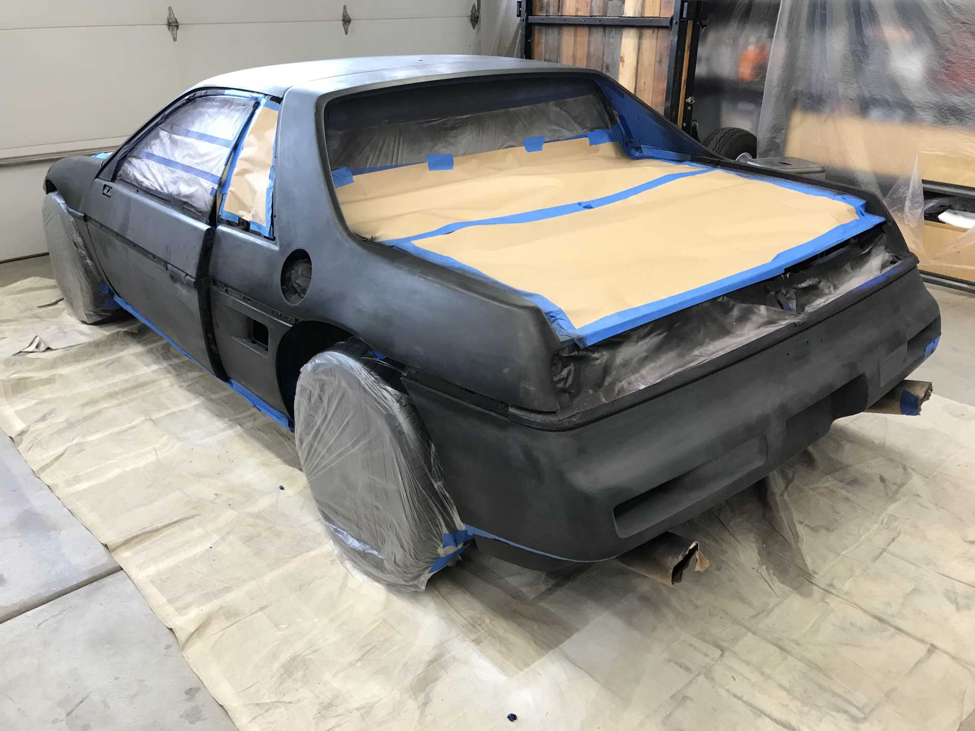
The color mostly went down without problems but I was disappointed with the number of layers needed to hide the primer. Maybe using a grey primer would have been a better idea. To hide the black primer took four coats minimum. Modern reds don’t contain lead like the old paints did so they are more translucent. This was problem #4, Had I known how thin this red was I would have painted the whole car black. It would have (maybe) taken fewer color coats, been easier to hide the primer and create a uniform finish. and it would have eliminated problem #3. I shot the body color with good results. Masking off the black areas when spraying red and the other way around when doing the lower doors, lower rear bumper and rocker panels. Problem #3 reappeared since I did miss some tape being properly down and I needed to repair the overspray which was a pain but eventually I got it right. It’s just time…
Color coat rear view
Color Coat front view
More to come soon. Really.
[This message has been edited by MikesFirstFiero (edited 01-30-2023).]
Looking good! Thanks for sharing your painting experience, I want to do something similar and repaint my car.
I have the Harbor Freight HVLP guns as well, I have only used them to paint chassis/engine parts and have always been satisfied with the finish, but maybe for painting the car I should spring for a better gun as well. I do like how easy that 3M one looks to clean, I did not realize how much more work the HF ones were to clean. I do usually fill the hopper with some acetone after painting and shoot a bunch of acetone to immediately clean out the tip. This has worked well for me as I have used the guns many times without any issues. I do take the entire gun apart to clean it, but just spraying acetone cleans up the biggest offenders.
Spraying acetone does work mostly. But for color & clear you will want the gun to be completely clean. I'd take the gun apart after every use and clean everything. Instead of acetone there are spray gun cleaners available. With acetone at $8 per quart it gets expensive to use like that. With the spray cleaner It costs less than a buck per cleaning.
Equally important for auto painting is the atomization and the width of the spray fan. A good fan should be about 10". Look at some of the many videos available on YT to learn about guns. Most good quality guns will cost about $200. Regardless of the gun you buy I reccommend you get an adapter to allow using the 3M PPS-2 Cup. These adapters are available for most any gun. With this Cup you never clean the cup and can put a cap on it to keep the left over solvent paint for the next coat (not the two part paints). Another thing to know about HF guns is that HF does not stock parts for your gun. Pro guns will have spare parts, nozzles and cups available through dealers.
The base+clear has another advantage for less-than-perfect application. You can sand the imperfections in the color to get rid of them before shooting with clear. But make sure to sand with grits up to 1500 to remove scratches since you will see them after the clear is sprayed. The clear can also be sanded so if you apply too much and get sags or runs simply flat sand them and then you can polish the entire panel. But sanding clear can run into the base color coat which means sanding everything and reshooting the clear. I've got some of this and some nicks and dings to reshoot the clear once it warms up some.
A note that I updated the injector photos of when I cleaned them last year. The photos taken by Bill of Mr.Injector really show how precise the injector parts are on the LFX.
[This message has been edited by MikesFirstFiero (edited 02-01-2023).]
Spraying acetone does work mostly. But for color & clear you will want the gun to be completely clean. I'd take the gun apart after every use and clean everything.
I take it fully apart to clean it every time, I was just saying shooting some acetone out of it does the majority of the work beforehand and stops the paint from drying as fast to give you a little time before it hardens fully in the gun.
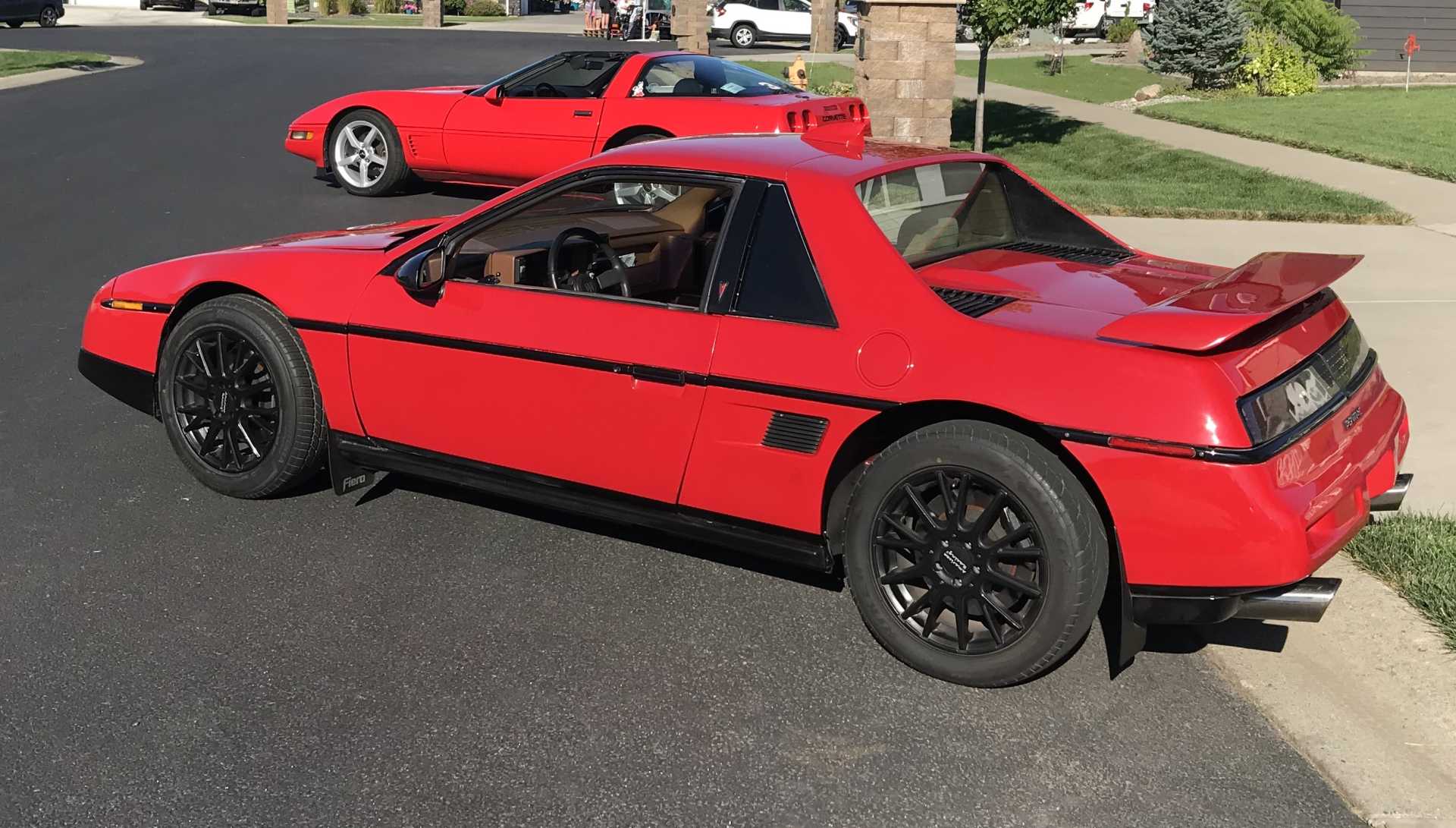
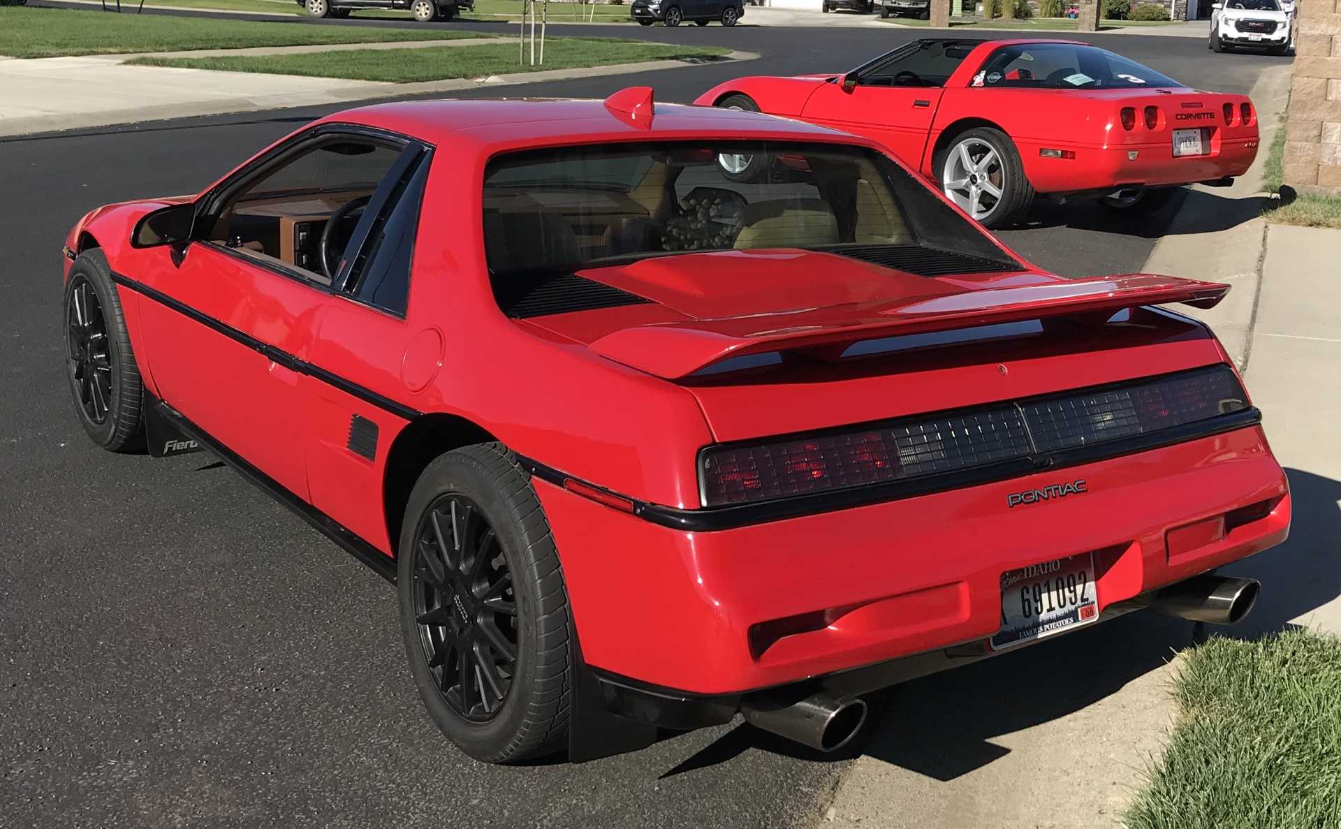
After lots of sanding, clear coating, more sanding, more clear, fixing drips, finding more flaws and fixing those flaws (mostly). Here is how it looks as of June 2022. It's a"Two Foot" paint job. Meaning from 2 feet it looks great. Fixing some minor defects and more clear this spring will make it hopefully a "Six Inch" Fiero.
Shown with my neighbors C4 Vette
I added a pair of rear mud flaps to keep the lower rear bumper clean(er).
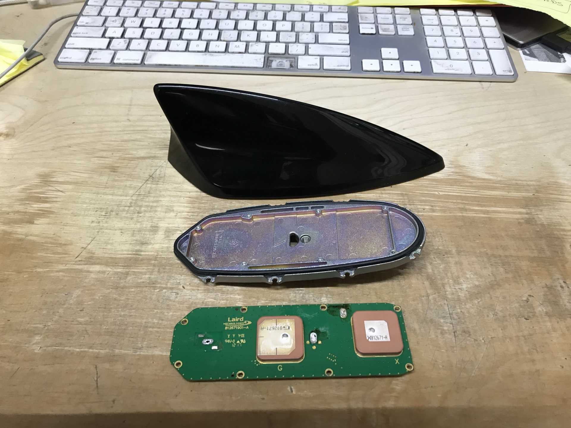
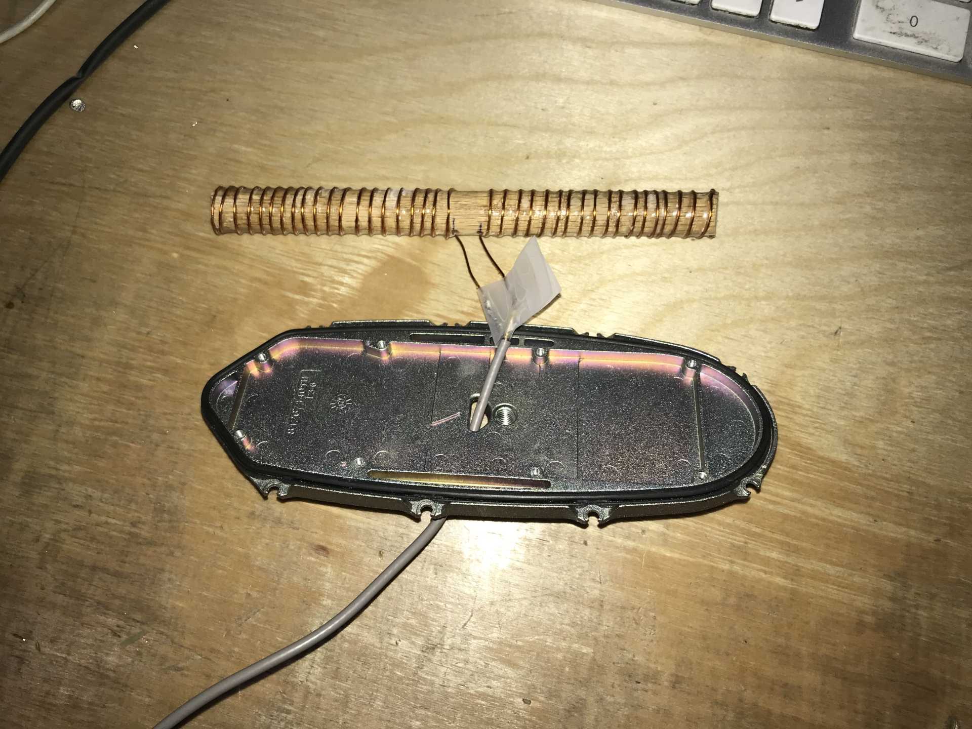
I've disliked the original Fiero antenna so I ripped apart the Impala Shark Fin and gutted it. This antenna was used for GPS and WiFi. The Impala AM/FM antenna used the rear window heater wires.
I kept the housing and base plate and wound a dipole 1/4 wave from copper wire and a stick. Each coil is 31" long to match the FM radio band. Then looking at the radio input It dawned on me that the radio input was single-ended (the shield of the coax was tied to common). So I wired the mid-points of the coil together and connected the coax to one end. The shield at the antenna was connected to a 10x10" metal tape on the inside of the roof that is a ground plane.
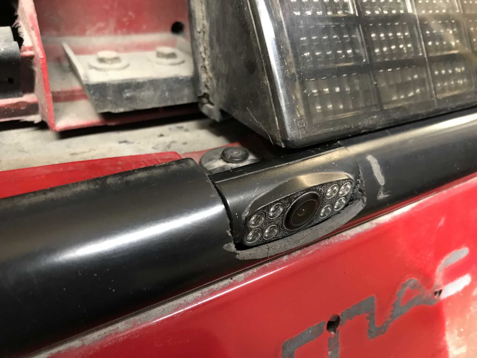
I had added a reversing camera to the license plate holder to work with the new Sony receiver. While it worked it was too close to the ground so I moved it to the center of the rear moulding below the tail lights. Now the view looks much better.
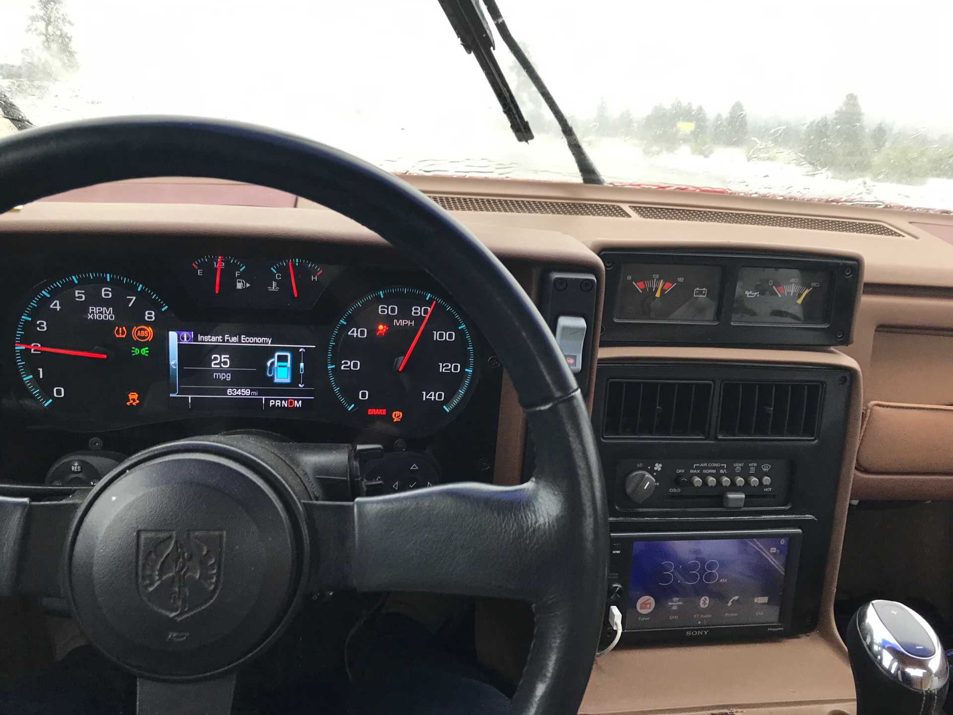
Here is what the instrument panel looks like while driving. The warning lights need to be dealt with. Notice the shift indicator says PRNDM. The Manual position uses the +/- buttons on the top of the Impala shift knob. The speedo is 10% optomistic so the real speed is about 75-76 MPH
I'm working on getting the lights on, high beam, turn signals and emergency flasher indicators on the IP (networked from the Impala Body Control Unit) to work with the Fiero wiring. I'm also working on the side markers to replace the single bulb with an LED strip. That turns out to not be so simple since the front markers change polarity depending on if the lights are on or not and the LEDs need a voltage regulator since they will be dimmer at idle vs at higher RPMs as the alternator output changes. More on that later.
[This message has been edited by MikesFirstFiero (edited 02-17-2023).]
Finally I may have a real reason for the misfire at high RPMs, fuel mixture too lean at high power. I thought about the fact that the LFX ran correctly in the Impala. What's different? Two things. The exhaust has been opened up with a restriction where the pipes from each bank come together removed and the pipe from there to the muffler is 1/4" larger and the total length is at least 10 feet shorter. The muffler is a Camaro transverse unit with one Borla resonator 12" long on each exhaust. So it flows better than the huge Impala mufflers. BTW I do still have the stock cats on each bank of the engine. The third cat on the 2" single pipe from the engine to the muffler (glasspack) under the car is no more. The original single pipe then split to two huge mufflers behind the rear wheels.
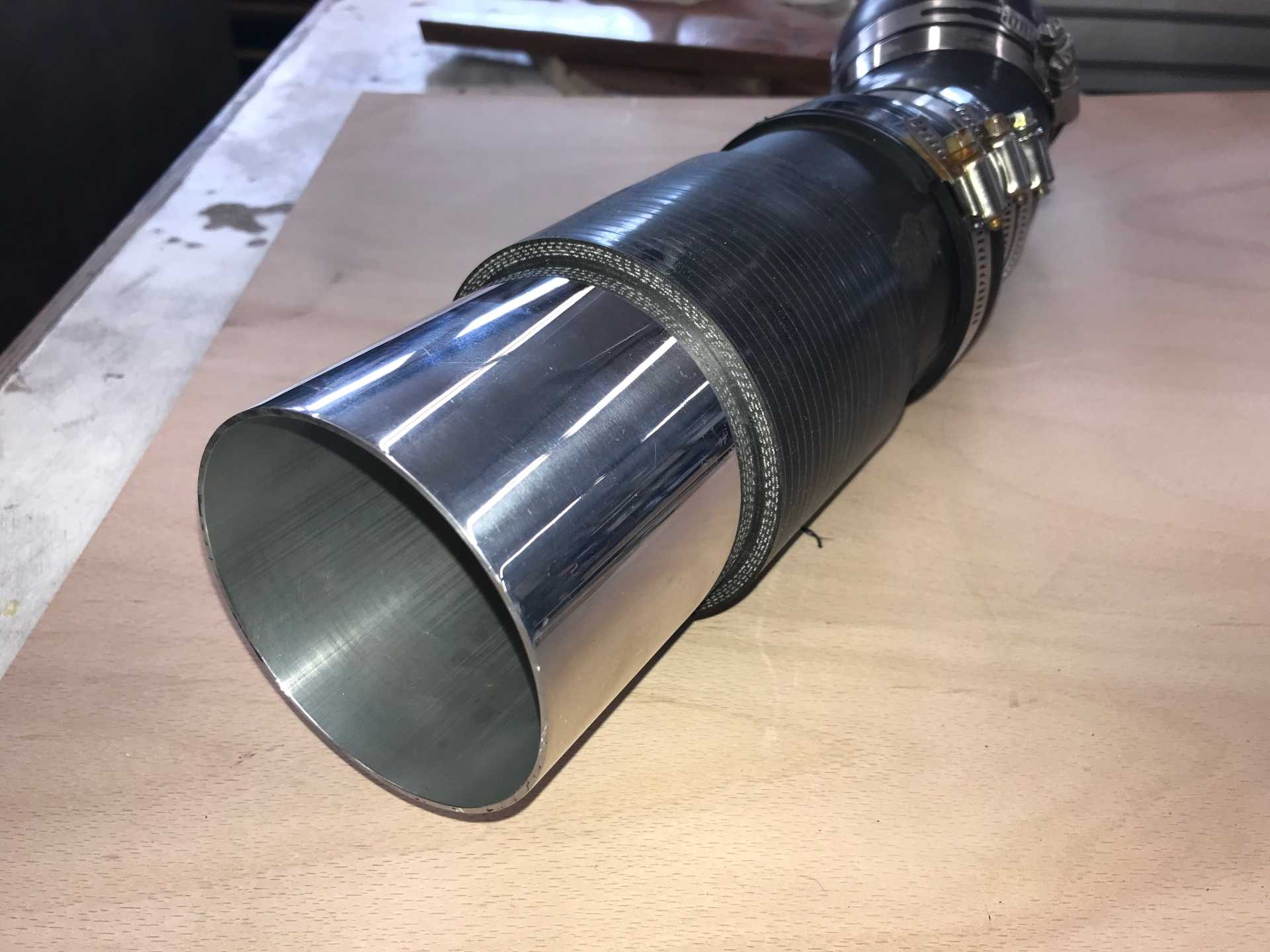
The intake is also better with a 9" cone to a 3.5" pipe to the MAF and 3" from the MAF to the Throttle Body with only two bends. The Impala was more restrictive and had a much longer inlet path. Could I now be getting too much air? I stopped over at Ace Hardware and got a flex coupling for 3" ABS which is 3.5"ID, same as the MAF. I also picked up a 2" to 3" ABS adapter which gives a restricted opening for air inlet of about 2" ID. I replaced the cone with this and gave it a run. No misfire up to redline in first 3 gears full throttle. Several runs with same result. The idle was crap at first until the ECU figured how to set the TB idle. Then it went back to 550-600.
Tomorrow I'll open up the restrictor to 2.5" and see what happens. If that works I'll go to 3" and continue until it starts misbehaving. If I go too far I'll get a new restrictor for $8 and drill it out to the size that works best. This restrictor will fit in the inlet pipe between the cone and the MAF. When I have the money I'll take it to someone who can tune the ECU to correct the mixture, make the speedo accuratre and remove some DTCs causing warning lights on the instrument cluster.
What this says to me is the intake and exhaust I used should permit engine to breath significantly better and make more power with the proper fuel flow map.
The MAF should give the right mixture for any amount of inlet air, within reason. 10% more airflow should not cause a problem.
I'm in my phone, so it's hard to go back and look at the pics. How much straight pipe do you have upstream of the MAF? Turbulence in the MAF can cause problems like this.
Also, if you think the mixture is lean, that would show up in the O2 sensor readings. You need to capture that data in order to verify your hypothesis.
Is there a screen in front of you MAF in the housing?
MAFs don't line bends within about 6" of the MAF inlet and you have your MAF right at the end of a 90 degree bend. Running a screen (flow straightener: http://www.saxonpc.com/airflow-products.html ) can help, but the larger the straight section before the MAF, the better.
All those silicone hoses can also flex, deform, collapse and change the air flow at high rpm. You might also want to consider using metal or plastic tubing for your intake tract and adjust the placement of the MAF to give it a straighter path.
Those are very good points you raise. Thanks for the advice.
No I don't have a flow screen and it sounds like a good idea to give a try. The hoses are flexible somewhat but each joint has a steel ring about 1" wide inside made from 3" exhaust pipe for the hoses to clamp on to. I don't see any signs of any bending but between the rings I don't know. Those hoses also have 1/4" thick walls and I'm not sure how much they actually do compress or flex. I'll figure out how to check this. The original Impala intake was a rigid plastic pipe (about 4" long) as part of the filter box. I cut the box off and trimmed the OD to fit the 3.5" 90 hose to the cone filter. I might be able to eliminate the bends somehow but I'm not sure there is enough length.
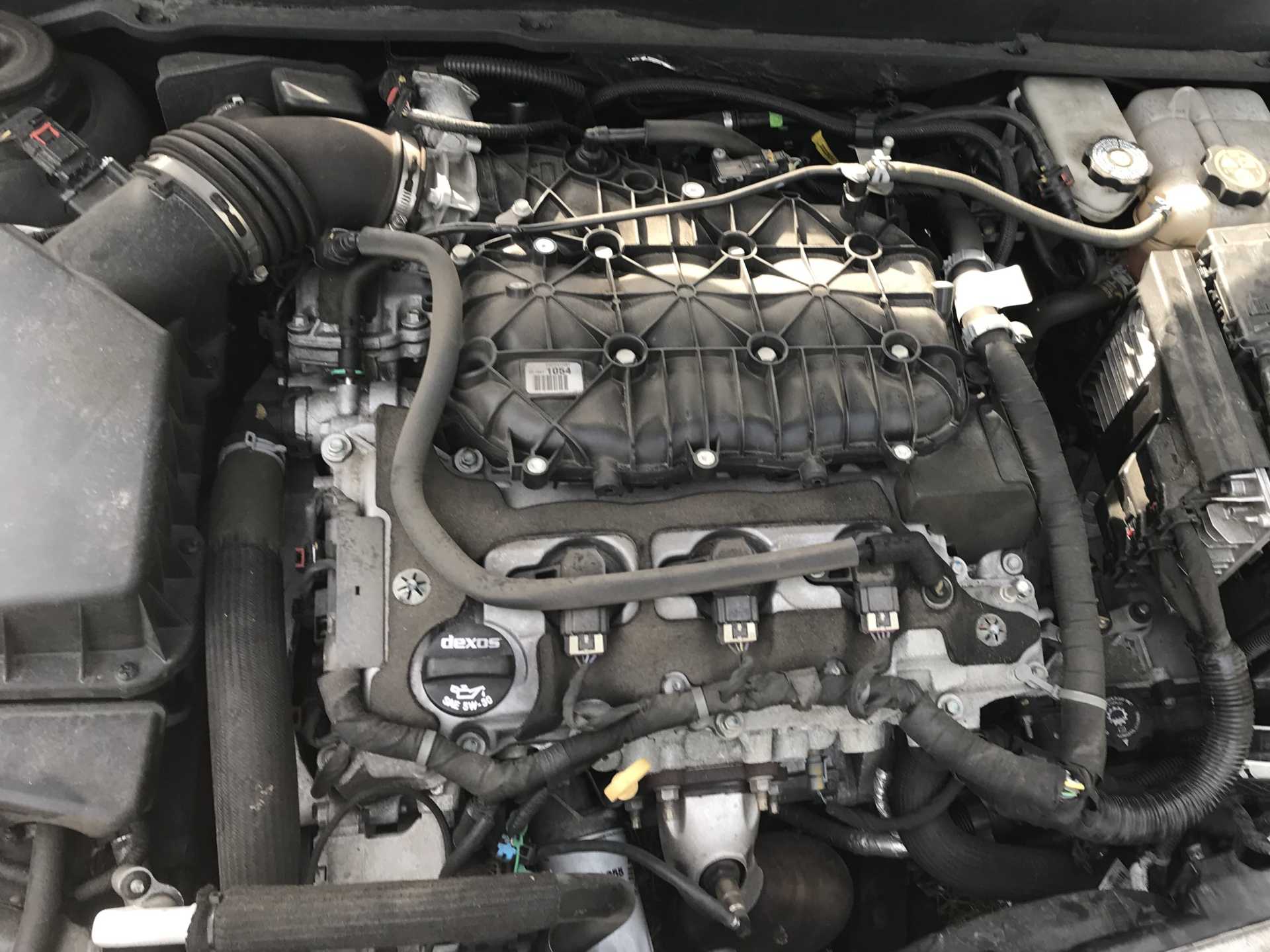
Here is the original Impala configuration. The front of the engine is at the bottom of the photo. I reversed the intake manifold to clear the shock tower. It does show the 4" straight path to the MAF with a bend afterwards to line up with the TB.
I've had some more results since the last post. With the opening increased to 2.5" ran quite well in a 30 mile trip up the road. Nothing was done to the car other than sitting around while I was at an estate sale. But on the way back it really misbehaved at first. As I got closer to home it seemed to behave better. I then opened the restrictor to 3" and drove it around today. That seemed to be a bit too much since the misfire came back some and the idle was really crap.
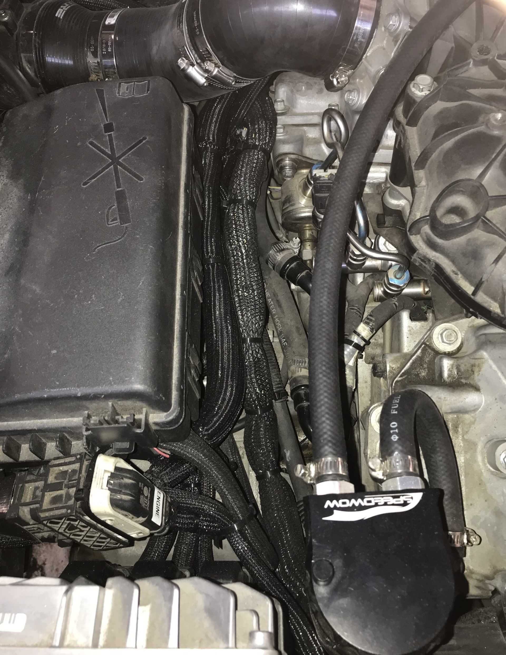
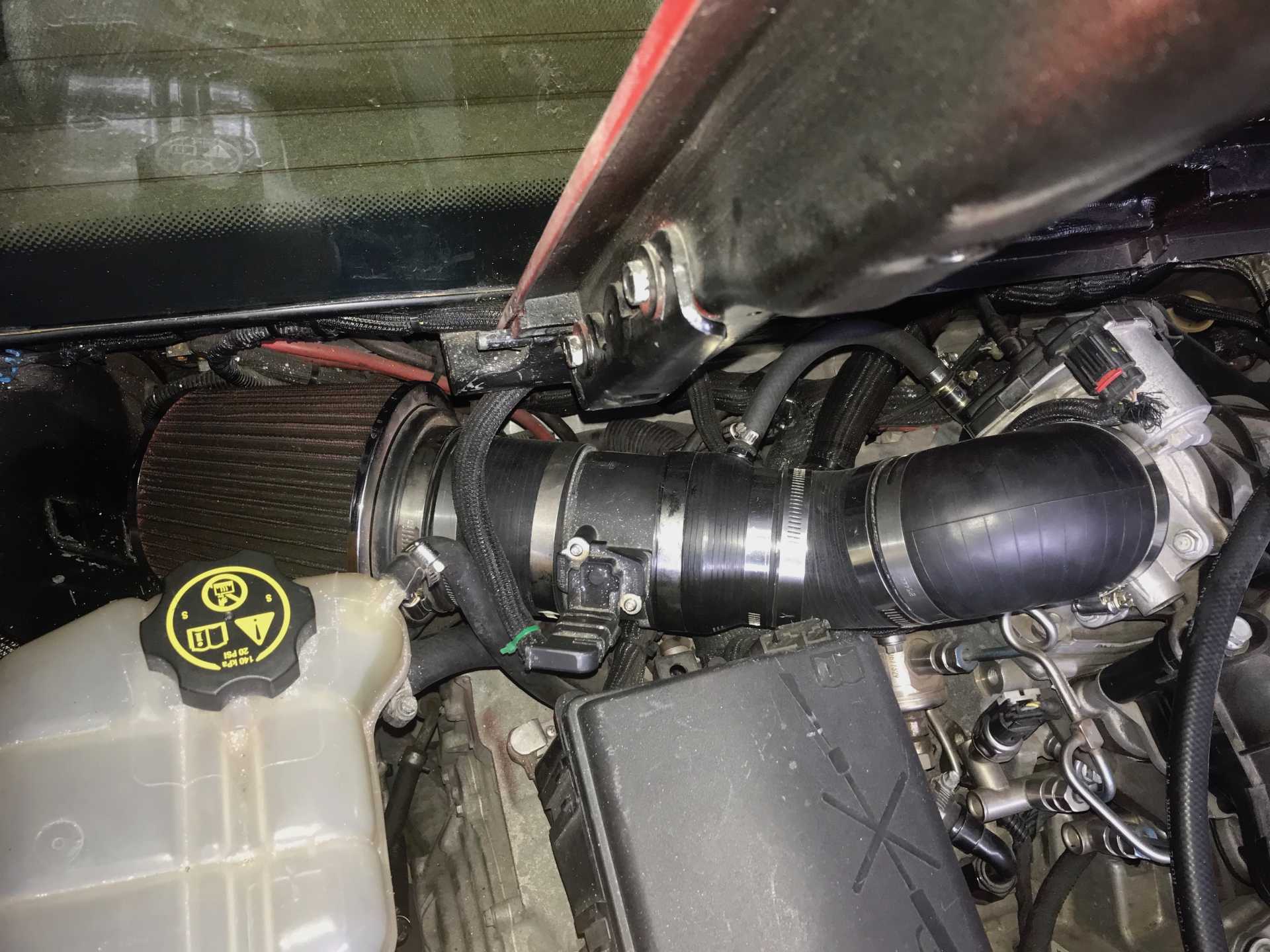
I've done a bit of reading and found that I might have introduced a problem with the air inlet to the valve cover for PCV. I took it from a small filter at ambient air not from the MAF measured air, you can see it in the photo hiding behind the TB. Guys on the Impala forum say this will cause problems since this would lean the mixture being unmetered air. So tomorrow I'll insert a hose fitting after the MAF to feed the source air to the valve cover. I'll also remove the restrictor and see how it operates. This would make the configuration more like stock. If you look at the Impala photo it is clear that the S-shaped air supply to the valve cover is after the MAF.
[This message has been edited by MikesFirstFiero (edited 02-18-2023).]
I've done a bit of reading and found that I might have introduced a problem with the air inlet to the valve cover for PCV. I took it from a small filter at ambient air not from the MAF measured air, you can see it in the photo hiding behind the TB. Guys on the Impala forum say this will cause problems since this would lean the mixture being unmetered air. So tomorrow I'll insert a hose fitting after the MAF to feed the source air to the valve cover. I'll also remove the restrictor and see how it operates. This would make the configuration more like stock. If you look at the Impala photo it is clear that the S-shaped air supply to the valve cover is after the MAF.
Lol... A lot of times it's the easy stuff. Be brilliant at the basics. If we'd known that from the info you shared here, we could have pointed that out.
Yes, MAF cars calculate fuel and timing on measured air into the engine, so the clean filtered air for the PCV needs to come from after the MAF.
Your setup with the external PCV filter would cause issues with unmetered air, but I would expect those to be low rpm issues where the % of unmetered air would be the greatest.
At WOT the high air velocity will force more air to the outside of the curve and cause more of it to miss the MAF that is centrally located. This changes the air measurement and throws fueling and spark timing off. A straight section or a flow screen will definitely help the high rpm issue.
I missed the air hose being after the MAF, I thought it was only filtered air. I'm working on fixing that, seeing if I can relocate the MAF closer to the TB and will order a flow screen. I didn't appreciate the absolute need for laminar flow across the MAF. Watched a couple of vids on YT which demonstrated the effects of unstable air flow. Again thanks for the advice.
[This message has been edited by MikesFirstFiero (edited 02-19-2023).]
it's worth mentioning that most cheap OBD2 readers can log fuel trims too, so you can see if the engine is actually going lean, or if there's some other factor causing your problem. I have one that works via bluetooth to my phone, it's pretty handy, I highly recommend something like it for anyone with an OBD2 car (everyone?)
------------------ "I am not what you so glibly call to be a civilized man. I have broken with society for reasons which I alone am able to appreciate. I am therefore not subject to it's stupid laws, and I ask you to never allude to them in my presence again."
I invited Lou Dias to trash me in my own thread, he refused. sorry. if he trashes your thread going after me. I tried.
The air coming out of the stock airbox is very laminar compared to a cone filter. On my WRX, going to a cone filter requires a full re-scaling of the MAF voltage to mass of air table. The aftermarket filter is identical ID to stock and has massive flow straighteners, and the cone filter is dead straight in line with the MAF and it even has a velocity stack at the entrance of the MAF tube to prevent any turbulent airflow.
So not only is a MAF very sensitive to any unmetered air entering it, but going away from the stock setup, even if maintaining the same ID tubing, still can require some MAF re-scaling to run as good as stock.
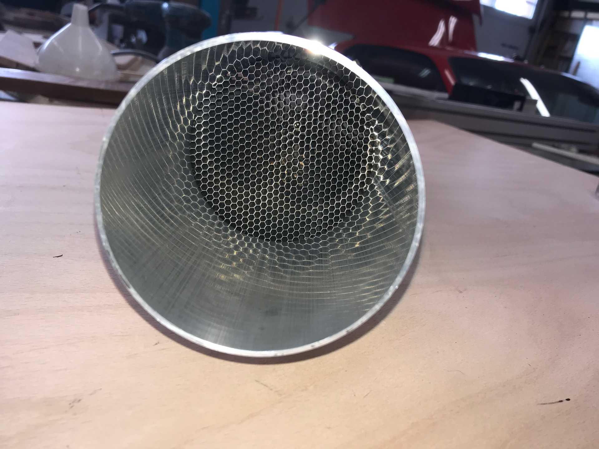
The honeycomb flow straightener came in the other day and I began to fit it into the plumbing. First I shortened the existing hoses to have room for the honeycomb to fit in place. I gained about 3 inches overall. I assumed that the air filter would not fit inline with the hose and would still need the 90 degree bend to fit. Originally the MAF housing connected directly to the elbow to the air filter. With the extra 3" of room it will fit in place.
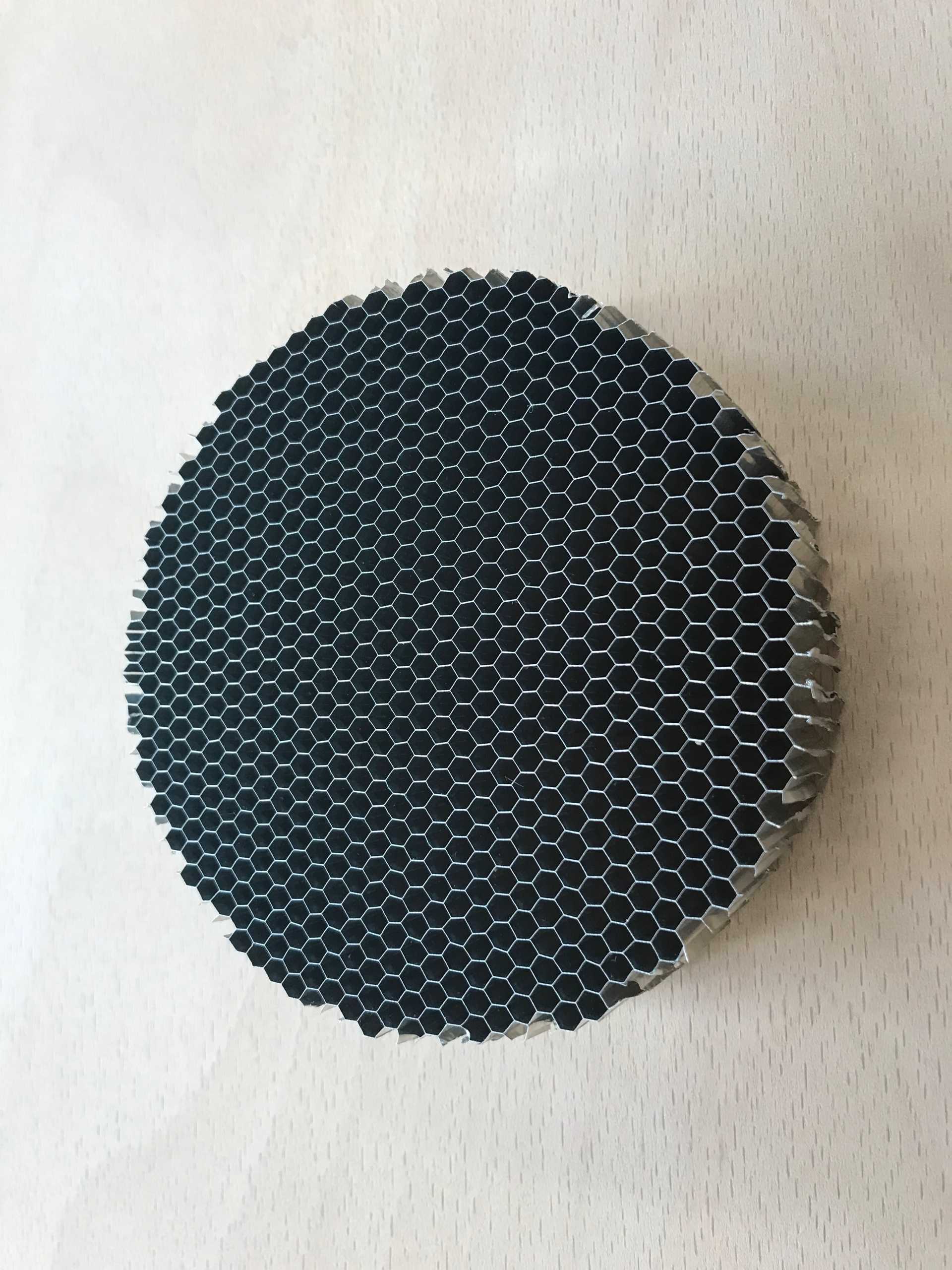
Here is the honeycomb material. it is 96mm in diameter and 1" thick. It's made from aluminum and is very rigid.
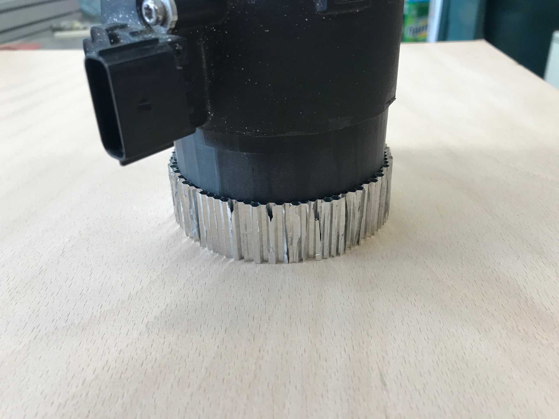
My TB is stock so I measured the fit and cut it smaller with my bandsaw.
Here it is fitted into the silicone hose connected to the MAF.
This aluminum pipe holds it in place and will connect to the air filter elbow. All parts are hose clamped together so everything has some wiggle room. The hoses can also be cut with a utility knife and a new blade.
View from the inlet end. The honeycomb is going nowhere.
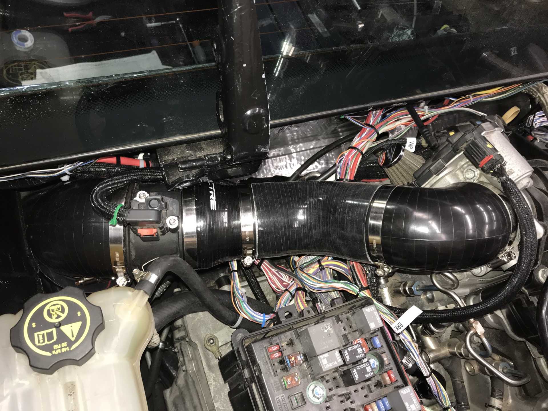
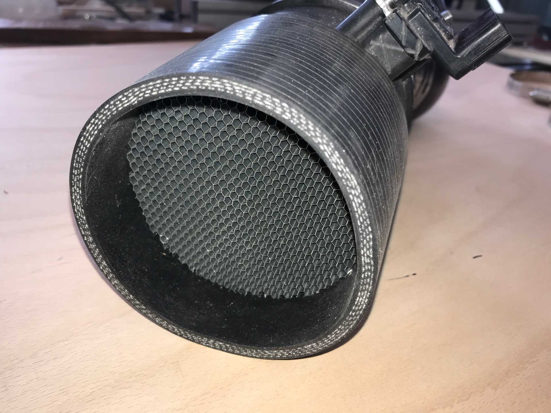
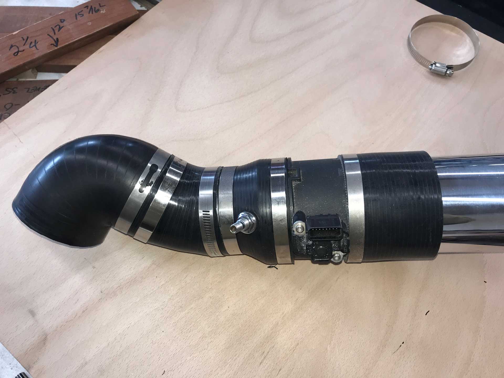
Here is what it looks like assembled. The schrader valve stem is the new air inlet to the valve cover. It has been drilled out for less restriction. The elbow connects to the TB of the engine. If I changed intake manifolds I could eliminate that bend but it's not in the budget for now.
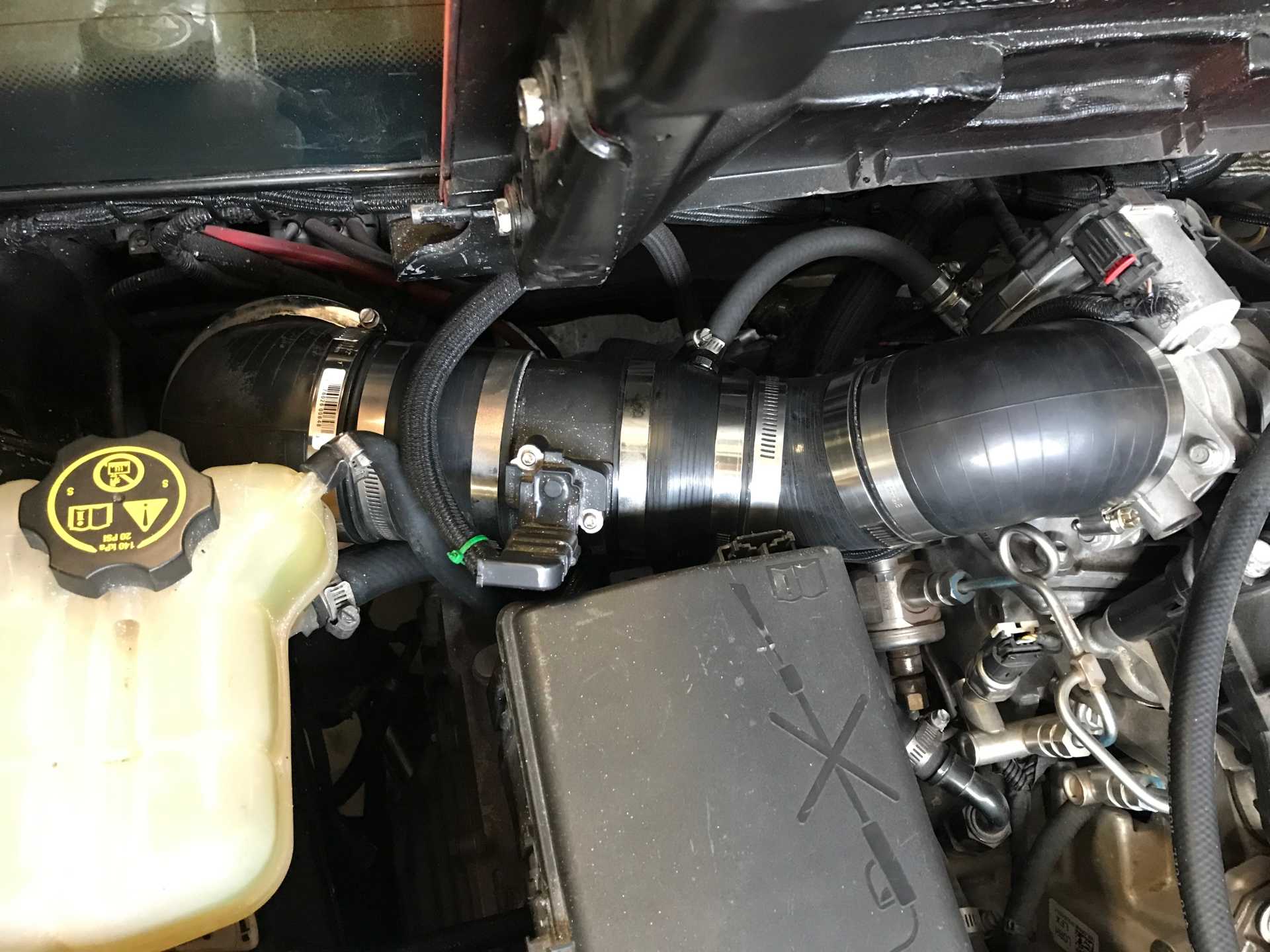
Here it is installed in the car and hooked up. Everything fits OK with little room to spare. I ended up trimming some more hose to make it fit better, about 1/4 inch.
Now for a test drive. It started normally and had a smooth idle. Idle had been somewhat rough in the past. After warming it up the results were good, call it a 7.5/10. At high RPM it still had some hesitation but was greatly improved over before. FieroGuru commented on the low end performance being affected, other than roughness at idle the low end up to about 4000 had no problems at all, that has not changed. The next step was to relocate the filter in-line without the bend. A bit more cutting and fiddling resulted in the filter being squeezed inline without interference.
Bingo! that did it. No hesitation or loss of torque at all. Strong accel up to 100MPH. I call it a 9.5/10 since there is always a way of making it better. I'll drive it around more and see if anything is amiss.
The material for the flow straightener is avaliable from Saxonpc.com. Give Jason a call and he will get you what you need at a reasonable cost. He was very helpful answering my questions and the honeycomb was well packed.
[This message has been edited by MikesFirstFiero (edited 03-11-2023).]
So what the straightener does is convert turbulent flow into laminar flow so the MAF has a steadier air flow. All those little holes in the honeycomb will drop the air pressure and increase the air's velocity so the MAF can have a linear airflow to use as a means to use the ECU's given calculations for that specific laminar flow. Once that laminar flow gets altered in any way, lets say the honeycomb is removed or installing a honeycomb with wider hexagons, like ZKennings said earlier, a re-tune of the MAF scale will be needed.
I am so over MAFs, sensor gets dirty, tiny leaks cause havoc, SD FTW.
Great you got your setup working! You should have a 2D MAF scale table, if you are able to tune it and have a wideband O2, you can log your commanded A/F ratios vs actual A/F ratios, and seeing as the rest of your motor is stock, any discrepancy will be in the MAF scale table being off, it is just MAF Voltage vs Airflow. You can plot the values against each other and use the % differences to adjust your MAF table by the same % at the correct values and you will be in business.
This works best if you can command the ECU to stay in open loop operation so there is no adjustment of the fueling and you can see how far off your MAF scaling truly is. On my WRX I change the value that open loop starts at, stock it is set at 13.6:1 commanded AFR values, so basically if you are driving and your load/rpm increases and your AFR table is commanding an AFR of 13.6 or below, it will switch into open loop. Otherwise the O2 sensor will adjust fueling to keep AFRs at 14.7:1 when cruising. In my ECU the max value you can command is 14.7 for the transition, I set it to 14.7 and I change any cells in the AFR table that are set to 14.7 to around 14.5, then the car is always operating in open loop, but you still have the wideband recording your AFRs for logging purposes, while simultaneously not adjusting the fueling based on its output.
It is not that hard once you are familiar with your different tables, I am not sure how tunable your ECU is, but this will return your factory drivability. Also I think you should have a wideband O2 as a factory sensor, if not you would have to add one.
[This message has been edited by zkhennings (edited 03-16-2023).]
Will, I had the same thought about needing the flow straightener. Having all the troubles without it I'll leave it in place. The parasitic losses are probably small and the reduction in cross section is minute. The honeycomb layers are only 0.0025 and 0.005 thick. It hasn't done anything wrong after another day of driving. I'll wring it out on a lonely road soon. And my fuel gauge now really tells me when I am empty. One win at a time.
I've not looked at the ECU tables at all. My reader is a Harbor freight ZR11 which does display some real time data but AFIK does not modify anything. To add to that issue my drivetrain is a 2018. The ECU and maybe TCU & BCU are VIN locked. I don't know if messing with the tables would disturb that or if there is some checksum or CRC on any/all tables that would need to altered if the data values are modified. When I worked on embedded controls we did the same thing as in the ECU; data was stored in tables and there was a checksum that needed to be correct or the elevator would not run other than in an inspection low speed operation. We did it not to keep others out but to insure that if something changed due to unknown reasons we would know about it and find out why.
If any of the experienced folks know of tuning tools that would allow parameter changes and the removal of DTCs I would be grateful for the info.
I've also completed refinishing the interior center console panels and window switches so they can now go back in place. Next up are the wheel alignment and touching up painting dings & errors before putting a new clear coat on.
Again I do appreciate all the advice provided, it continues to be a great help.
[This message has been edited by MikesFirstFiero (edited 03-16-2023).]
Looks like the 2017-2018 Impala with 3.6L is supported by HP Tuners. You might want to call them with a list of codes and things you want to change to verify their software can do it. https://www.hptuners.com/vehicles/gm-tuning/
Today the weather was dry and I got a chance to do one run. I let it shift automatically about 6500 RPM, Car weight estimated 3200, 0-60 5.1sec, ET 14.0, Speed 100MPH. That works out to be about 250HP at the engine. Those numbers are calculated from the video of the Instruments with a speedo error correction and are rough. I do have an old G-meter that I'll get working for better confirmation. I'll get some more numbers in the next week or so with manual shifting, which is quicker. And not a single misfire from the engine. I quit at 108 MPH and it was still pulling well.
Here is a copy of my calculation spreadsheet
[This message has been edited by MikesFirstFiero (edited 03-17-2023).]
Awesome Job!! I am going to do the same conversion this winter, (23) so I am in the process of gathering parts and info. what all modules did you have to use from the donor car? if you had to do it again, what would you do differently? is there anything you wish you would have done that you didn't do?
[This message has been edited by rglasco101 (edited 05-22-2023).]
I worked the problem the other way. Bought a wrecked Impala complete, ripped everything out and began removing things until it stopped working. My donor was a 2018 which means all the main modules must be from that specific car otherwise you will need to have someone code generic modules to work with your system. 2017 to 2014 would be a better choice since it lacks the anti-theft "features". Make sure the engine is the second gen LFX, same with the 6T70 if you use that. Earlier ones have some problems.
Things that were needed. Harness - About 1/3 needed, rest removed Engine Fuse Box - Some fuses and relays repurposed, under the dash fuse panel not needed ECM - Mounted to rear firewall BCM - Lots of signals are not used, but some were needed CCM - Controls Fuel Pump, emissions and sends Fuel pressure and Tank level to other modules & instrument cluster SDGW - Serial Data Gateway interconnects the different networks TCM - Part of the transmission talks to the ECM & instruments Instrument Cluster - fuel level, lights & turn signal indicators, speedo & odo from TCM data, information display works too. Gas pedal - electronic to the ECM Shift knob - for manual shift feature Shift indicator - replaced Fiero unit (not really needed since instrument cluster also shows gear you are in. Key Fob, sensor coil and module to detect the Fob Push to start switch Ambient temp sensor for ECM Fuel pressure sensor (55 psi low pressure) Fuel Pump, fuel level sensor (needed to be reworked). Fuel filter with regulator from a Corvette
The Impala electronics think it is still an Impala with some modules not working. Haven't spent the money to get some warning lights and messages deleted yet. The power wiring from the Impala fuse box feeds the Fiero fuse box for Always Live power and Hot In Run power. The Fiero wiring is mostly intact. The engine fan control now comes from the Impala low-speed fan relay. That was a mistake, it always runs. Need to move it to a different signal so it it only runs when needed.
Your conversion could be much simpler but I wanted the Impala instruments, push-to-start, transmission control and cruise control to work. Cruise control did not work out, it requires emergency brake module data and ABS data which I did not keep. Probably the biggest amount of work in the project was the electronics and wiring. The custom axles required time to figure out and the cradle and engine position took a while too.
Things I would do differently. Shift the engine/transmission to driver side 1/2" more for better access to the cam connectors (three per bank). Figure out the cruise control. Have a more accurate fuel level sensor, it is now accurate at empty where it is really needed but reads low above that. Maybe figure out how to use the camaro intake manifold. Work out better motor mounts, there is more vibration than I like at idle.
Things I like. Minimal weight increase, rear end is more planted to the ground, but I also added the rear sway bar. Goes quick, gets very good fuel economy when cruising. Exhaust is quiet around town and on the highway, and louder when pushed. Never fails to start. Except for a few clues it looks mostly stock inside & out. It did not cost too much, with two sets of wheels & tires, car and everything else about $9,500. Driving it makes me smile. A Lot.
If you have questions when you get on with your project just ask, I'l try to answer as best I can. I suggest getting a real Fiero shop manual and subscribing to the Mitchell 1 service for the donor car unless you purchase a standalone harness and electronics. Best of luck.