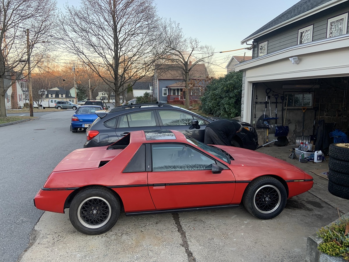
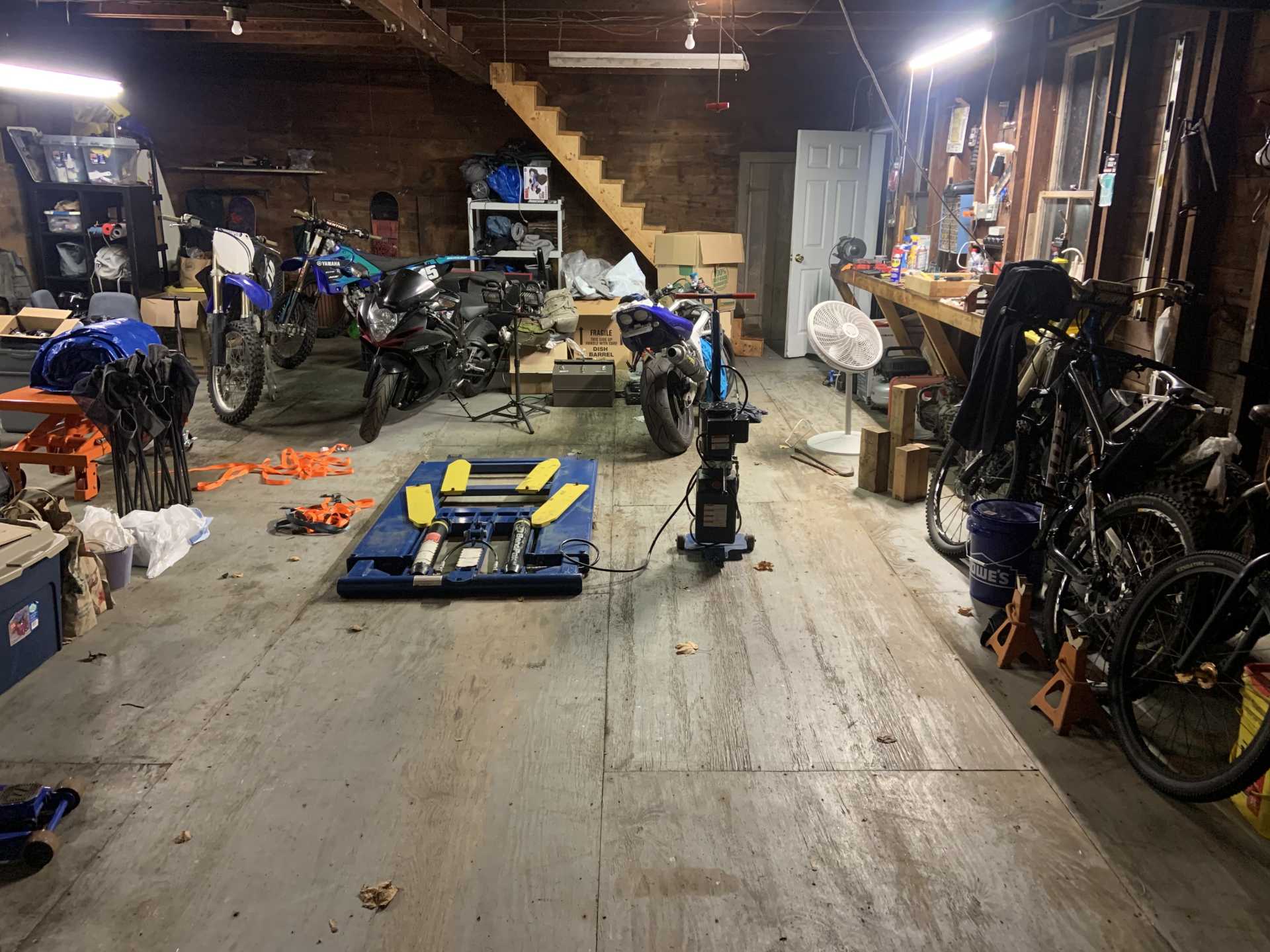
I put the Fiero away over a month ago, I cleaned it up nice before pushing it to the other driveway and covering it for the winter.
My dad and I were swapping our cars over to snow tires. I convinced him to get a set of Pilot Sport 4S tires for his summer rims on his stock 2015 Impreza, I wonder if it is the only stock Impreza with those tires. My gold winter wheels and tires can be seen in a stack in the garage.
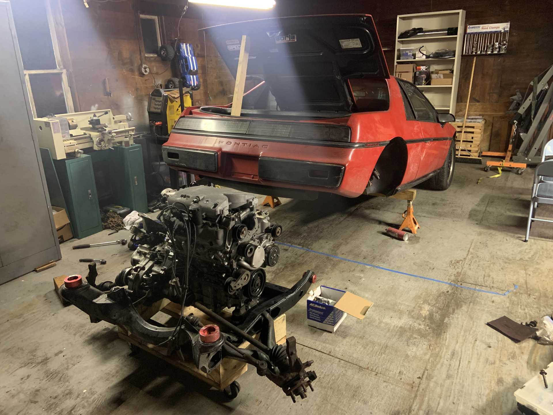
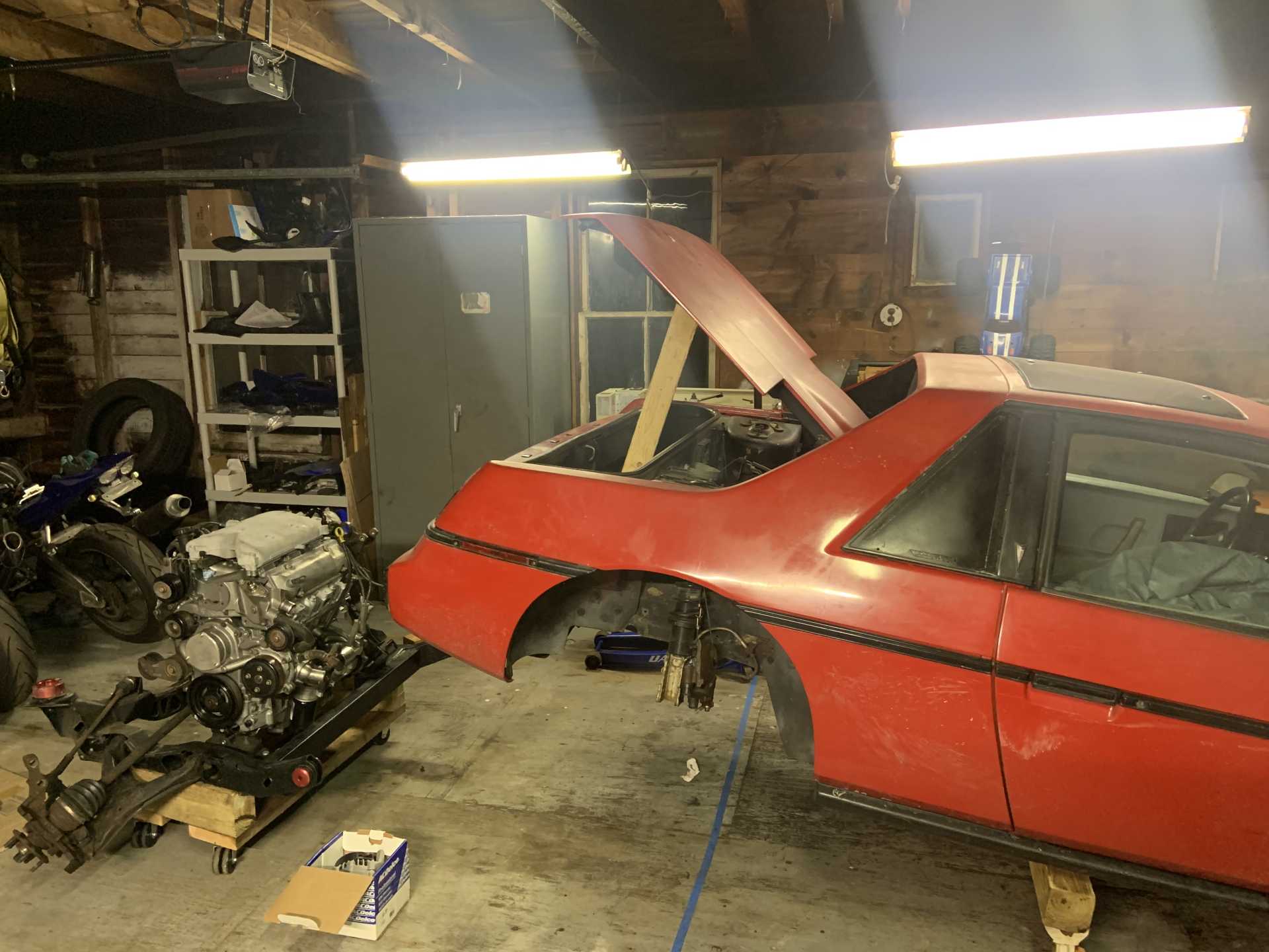
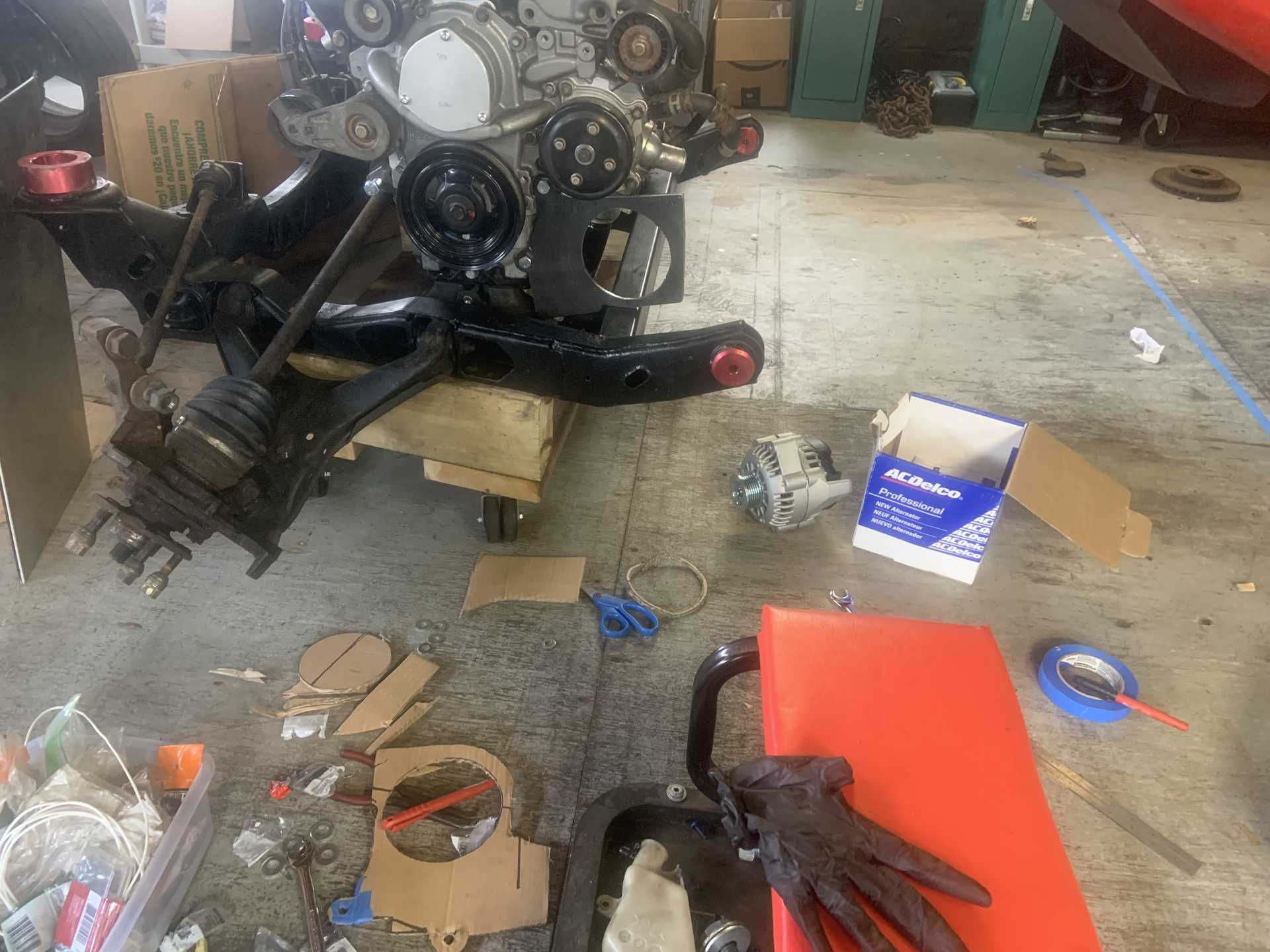
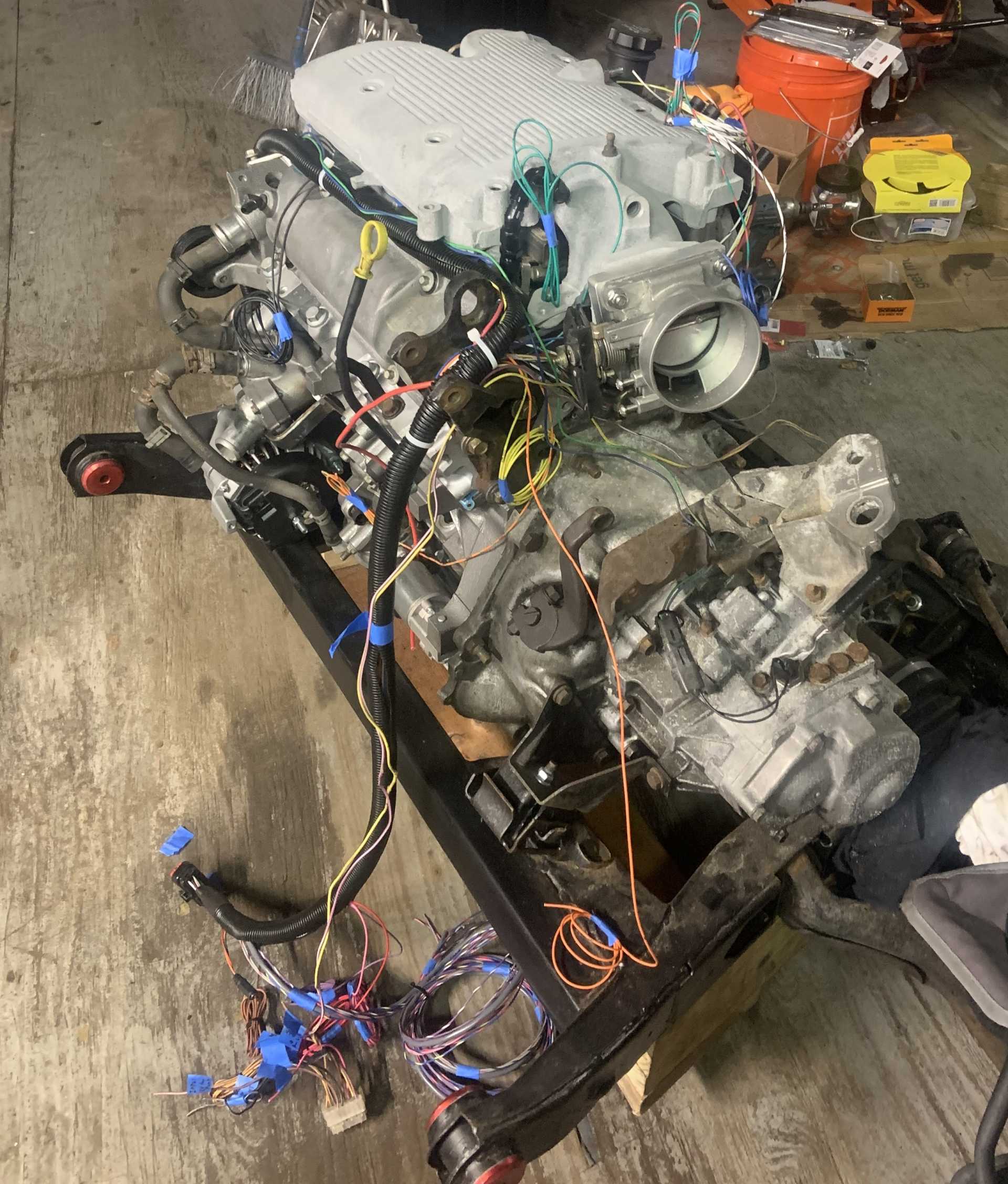
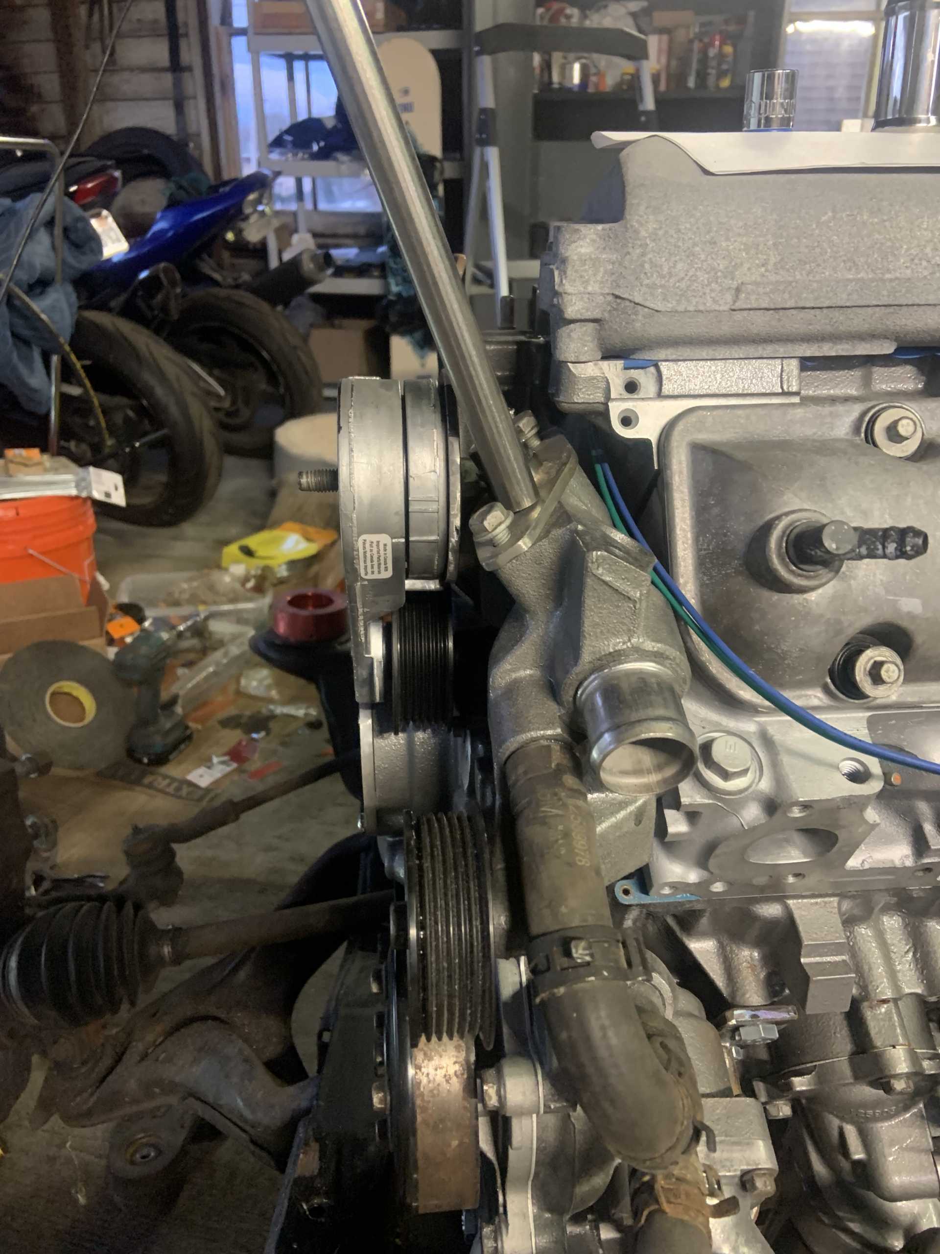
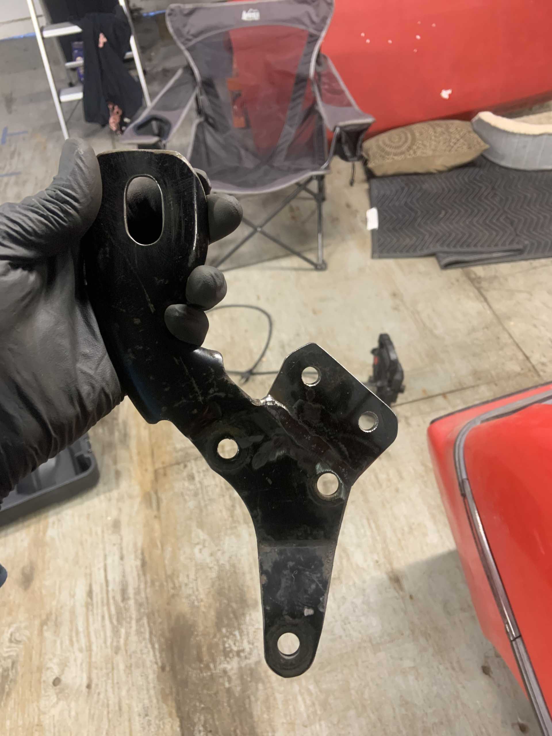
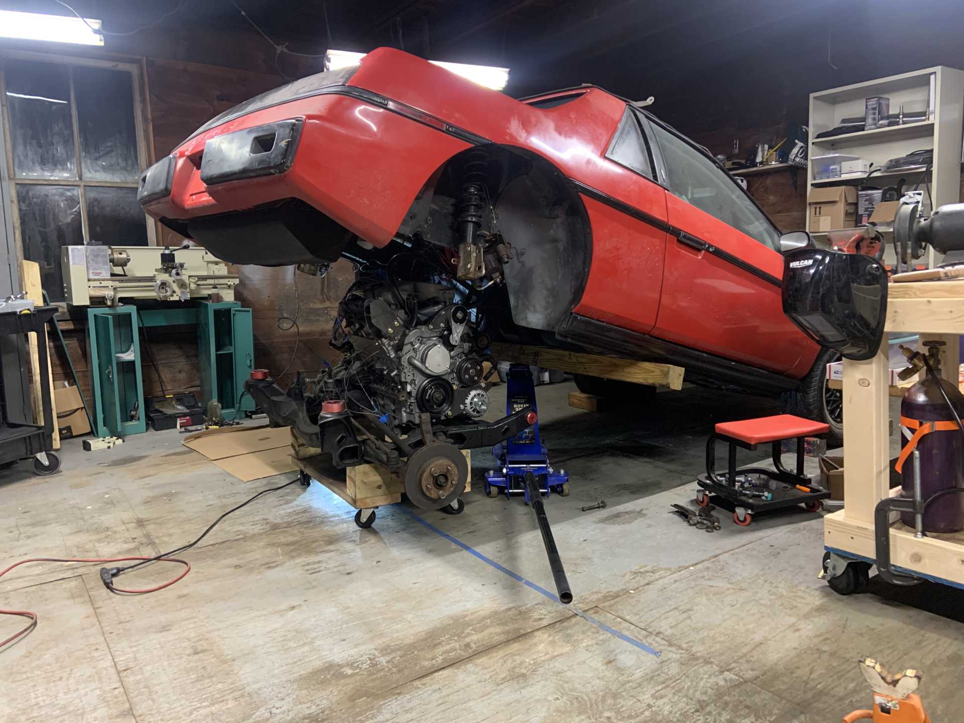
I put everything away so my parents can park in the garage for the winter. I did remove the engine from the cradle prior to re-installing it and put it back on the stand after taking some measurements. I hope to get to make the alternator bracket for it as well as wrap up other little details so it is ready to go come springtime.
I got my wideband O2 and a gauge installed in the WRX and I have been tuning it constantly. It is pretty fun and I am getting a really good understanding of how the tune works. I may switch to a custom ROM in the near future that would allow speed density tuning, the ROM is based off the Group N rally car ROM. But learning how to dial in the VE table will be very useful for getting the Fiero running. The tuning experience I am getting in general will be really useful for getting the Fiero running well. I had intended for tuning the Fiero to give me the experience I need to tune the WRX, but the tables have turned. The WRX was in a sad state before rebuilding, it had boost issues and was only hitting 9psi, and there was a massive pre-turbo exhaust leak and the motor only made 90psi of compression. With the new bottom end, long tube headers, and having fully gone through the boost lines and then tuning on top of all of that, now I hit 18psi of boost at 3300 rpms and the car is pretty damn fast. I bought a big 18g turbo for it good for 450hp, but I need the Fiero running and driving before I possibly blow the WRX up
I have been spending all my time working on the bus, it has been very cold working long hours outdoors in 20-30* weather, but it will be awesome once the frame is repaired and I can work in the heated interior of the bus.
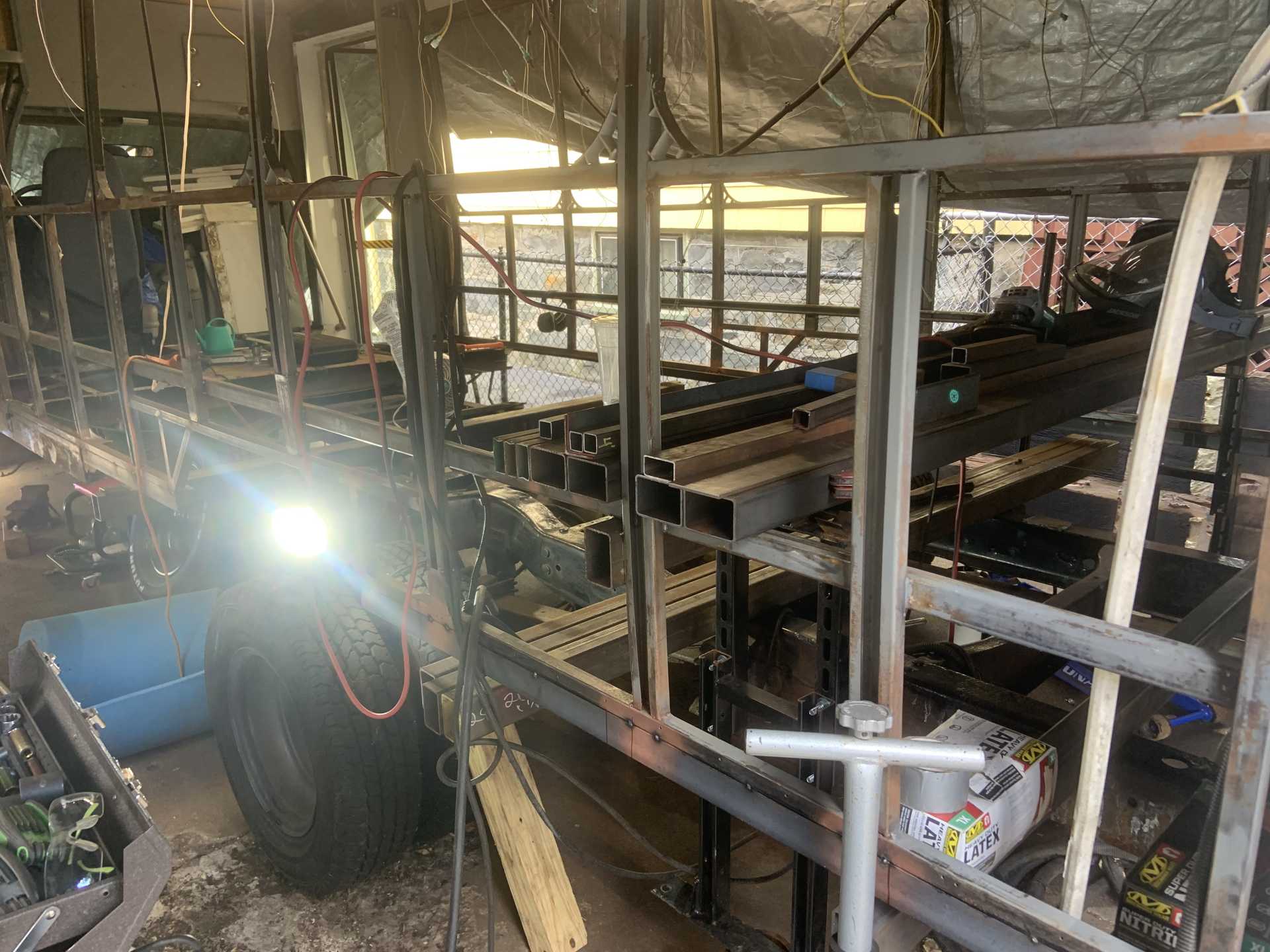
I bought ten 8' long 2"x3" 11ga rectangular tubing from Metal Supermarket for replacing the crossmembers. Should be really strong and make it much stronger in the event of a rollover. First I am repairing the side frame so I can jack the bus up from the rear to insert the new crossmembers. Here is some repair I have done to the side frame so far.
I just made a build thread for the bus if anyone is interested. Hopefully I get a lot of progress done and am able to use it before the end of the snowboarding season. Once the frame repair is done I will bring my welder back to my parents and work on Fiero fab.
Also I have gone snowboarding 5 days now and my knee feels better and better every time. Tearing my ACL has been a rough journey but the Fiero is almost ready to go which would have never happened had I not torn it, and now my knee is doing great and I am feeling good. Tomorrow is 9 months post-op and my ACL should officially be fused to my bones again. My PT told me that the soft tissue doesn't fully heal from the surgery until a full year out, so I still have a little ways to go before it is 100%, but it feels 90% right now.
Hopefully I finish up the bus frame within the next month and can post an update of working on the Fiero's alternator bracket.
Been working on the bus and the side framing is all repaired, about to finally put in new cross bracing. I need to figure out a good solution for body mounts, I may also forgo them altogether and bolt frame rails right to crossmembers. I have seen older busses built that way, and I am not going to have a ton of passengers in need of comfort like an actual bus. But if you have any recommendations let me know, I have found some poly body mounts for a jeep, they need to be ~2" diameter and Ideally around an inch thick, but I have only found ones 1/2" thick.
My parents house flooded while they were away when the boiler fried and some pipes froze. It was a big problem as the leaks were all the way in the top floor and it still flooded the basement. It is currently an unusable space to work on things. I am honestly tired of working at my parents so I am trying to locate a shop space in northern MA/southern NH area that I will split with a few friends. It is a good time to do it now because I had to box all my car stuff up anyways for the garage and basement to be repaired. Hopefully I can do a couple brake jobs a month to offset the costs of renting a space. The other benefit is I will probably have an indoor space to work on the bus instead of an apartment driveway in the city which will be really nice.
I have been tuning the WRX for a few months now and I have gotten pretty decent at it, I have made it pretty quick and really tuned it to feel how I want it to feel. I have gotten comfortable tuning the fueling, timing, and boost. I have increased stock boost from around 13.5PSI to 20PSI and it has responded very well to the changes after extensive logging and tuning. I have bigger fuel injectors and some other parts to throw into it that I will have to tune for, just trying to gain some experience before getting the Fiero running, but it now seems like it will be a very simple task. I also cannot wait to tune with Tuner Studio with the MS because I have been opensource tuning the WRX and I have to create graphs for all my logs which output as CSVs. I don't have a macro or anything setup so it takes a while and there is no tuning on the fly like with MS. I think it is going to be much more enjoyable tuning the Fiero.
And finally I got in 30 days of snowboarding before partially re-tearing my ACL going off an unexpected drop in the woods. I got an MRI that told me this, and while the doc says I need surgery, the knee feels pretty stable so I am going to try and rehab it without surgery. I was almost a year out from surgery when it re-tore so I don't have a ton of faith in restarting the entire process, especially when I landed the drop fine, knee just was still not strong enough to handle it. And I had been working out 4 days a week, doing yoga twice a week, and snowboarding at least twice a week, so I don't know what I could have done differently to prevent injury other than not snowboard. Been mostly waiting for swelling to go down before starting PT again. And if I get it really strong and it still has issues, I will get surgery and have a much better starting point with a strong knee. I'm gonna be really bummed if I miss a second season of motocross in a row, hoping to just miss half the season, hoping a good 3 months of rehabbing will let it heal up to better than where it was when I re-tore it.
Hopefully find a workshop space in the near future and get all my belongings transported there and can get cracking on the Fiero.
Have not touched the Fiero since last year, I have been focusing 100% of my efforts on the bus to get it drivable by the end of August because we are moving out of our apartment and into our new house!
The new house has a 700sqft detached garage/barn and it will be perfect to work on the Fiero in. I am normally working at my parents house and I have to drive there, set up all my tools, do my work, then pack everything up every day before leaving.
Now I will be able to cruise through projects and work late into the night without disturbing anybody, so I am beyond excited.
At the end of August I will hopefully be driving the bus to the new house (And not tow it) but we will not actually be living there until the first of October. I will be living at my parents house in the meantime, and with no bus to work on I plan on making progress on the Fiero starting in September.
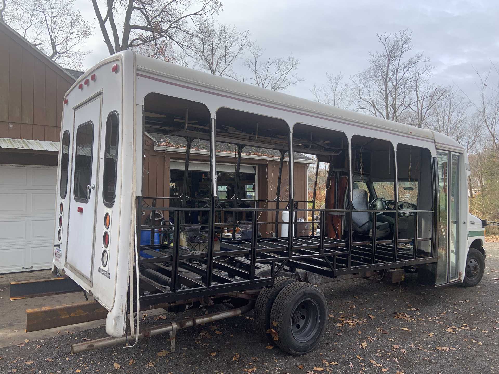
Here is the bus currently LMAO wish me luck
Probably going to take a week off to bang the rest of this out. It is closer than it looks to being structurally sound, it is ready to accept the new crossbeams and the frame is almost all prepped, just have a few more reinforcing plates to weld over the last remaining thin spots.
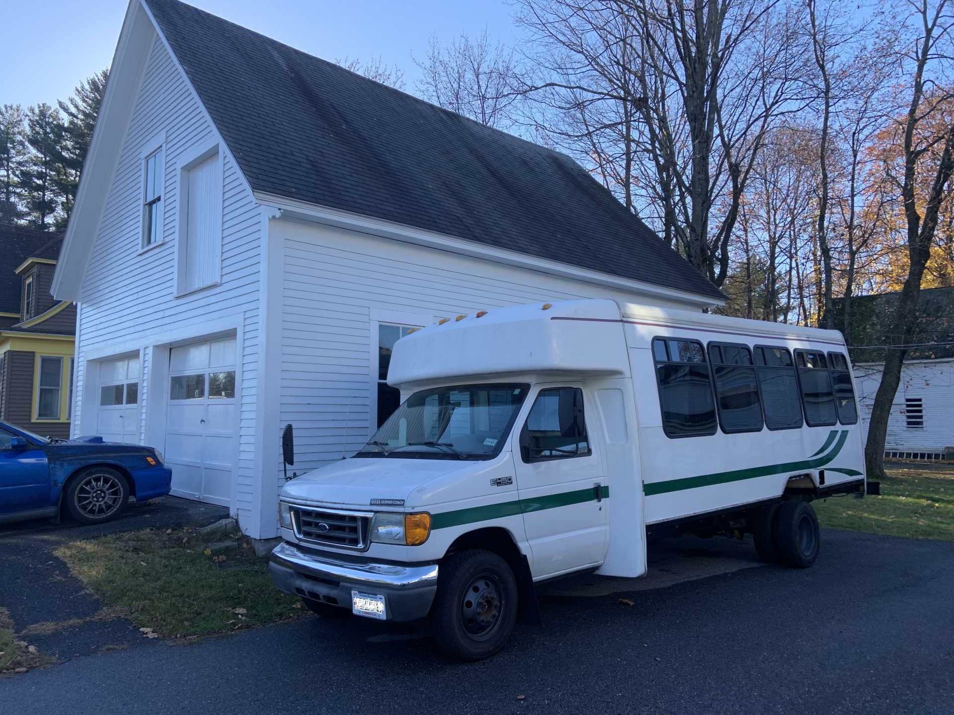
Bus got finished enough to drive to CT, threw the walls, windows, and a makeshift plywood floor in it to load it up and make the drive without getting pulled over.
Unfortunately things did not go to plan while living at my parents for the month of Sept, they were getting their kitchen re-done and it was supposed to be wrapped up before we stayed there. And it was not even close, resulting in a garage full of kitchen crap and a sad Fiero.
Fast forward to October first and we moved into our new place, the barn is awesome. But I really wanted to finish up the bus in CT and use all my free time to get that done and get it up to NH.
Fast forward to now and the bus frame was completed and painted, the chassis extended, and the bus made the almost 3 hour drive up to NH.
It was a lot of work and I am glad to be done with it. On the bright side, I have 0 fear of making my own subframes and suspension for the Fiero now.
I also drove down to NY and grabbed this Bendpak 6000 lift that I need to recess into the floor of the barn, but it will be so useful for working on my vehicles. Got a killer deal on it. Lifts up to 47".
Now that the bus frame is done and it is up at my house, I am making moves to get the Fiero up there to finish it up over the winter. Going to borrow a buddy's truck and rent a uhaul trailer to get it done, if not this week then definitely next week! Writing it here to stay accountable and get it done, it has been way too long. But glad the bus is in a great spot to be usable this winter, it needed an insane amount of work and would have never gotten done if my focus was split.
Took longer than I planned but made things happen.
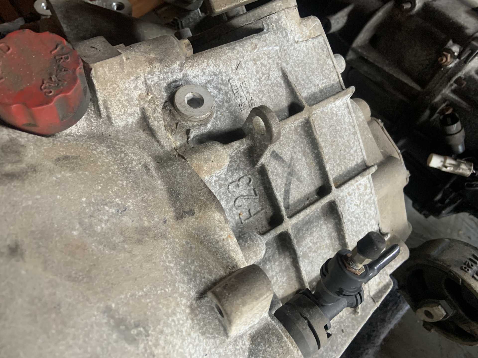
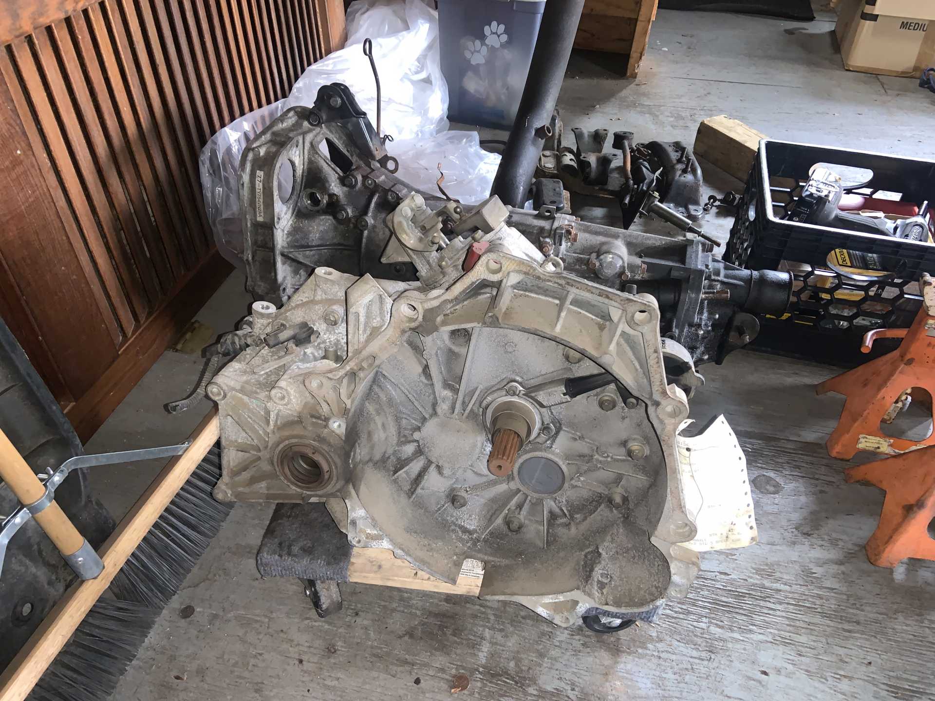
Picked up a 62,000 mile F23! Figured I should have the trans ready to go for when the Isuzu goes kaboom. Came from an 01 2.2 Cavalier. Note how dry it looks, not a spot of seepage on it.
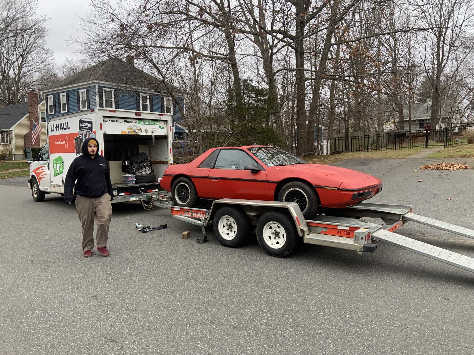
I also had a weekend day to spend bringing stuff from my parents place to my place, including the Fiero.
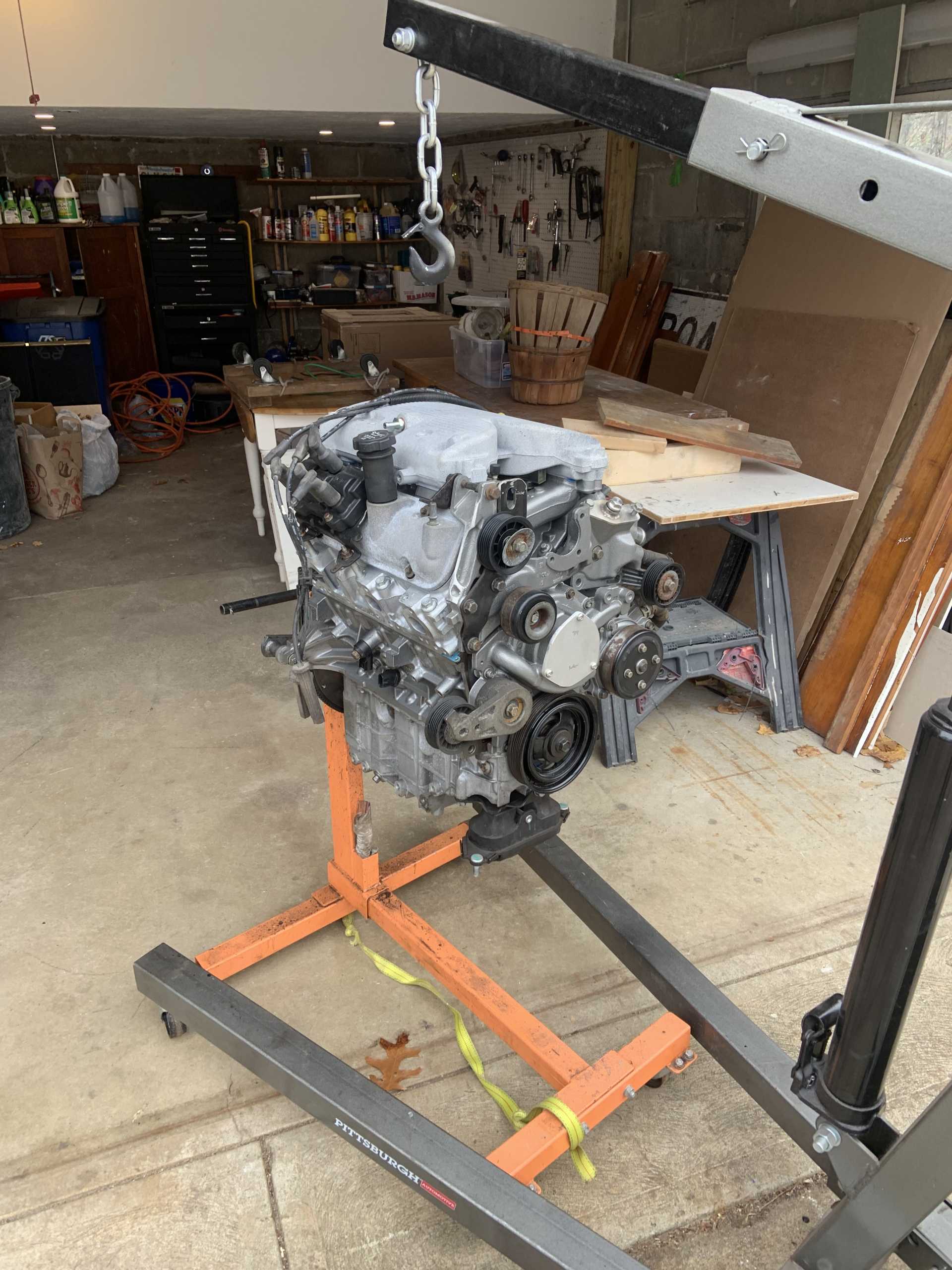
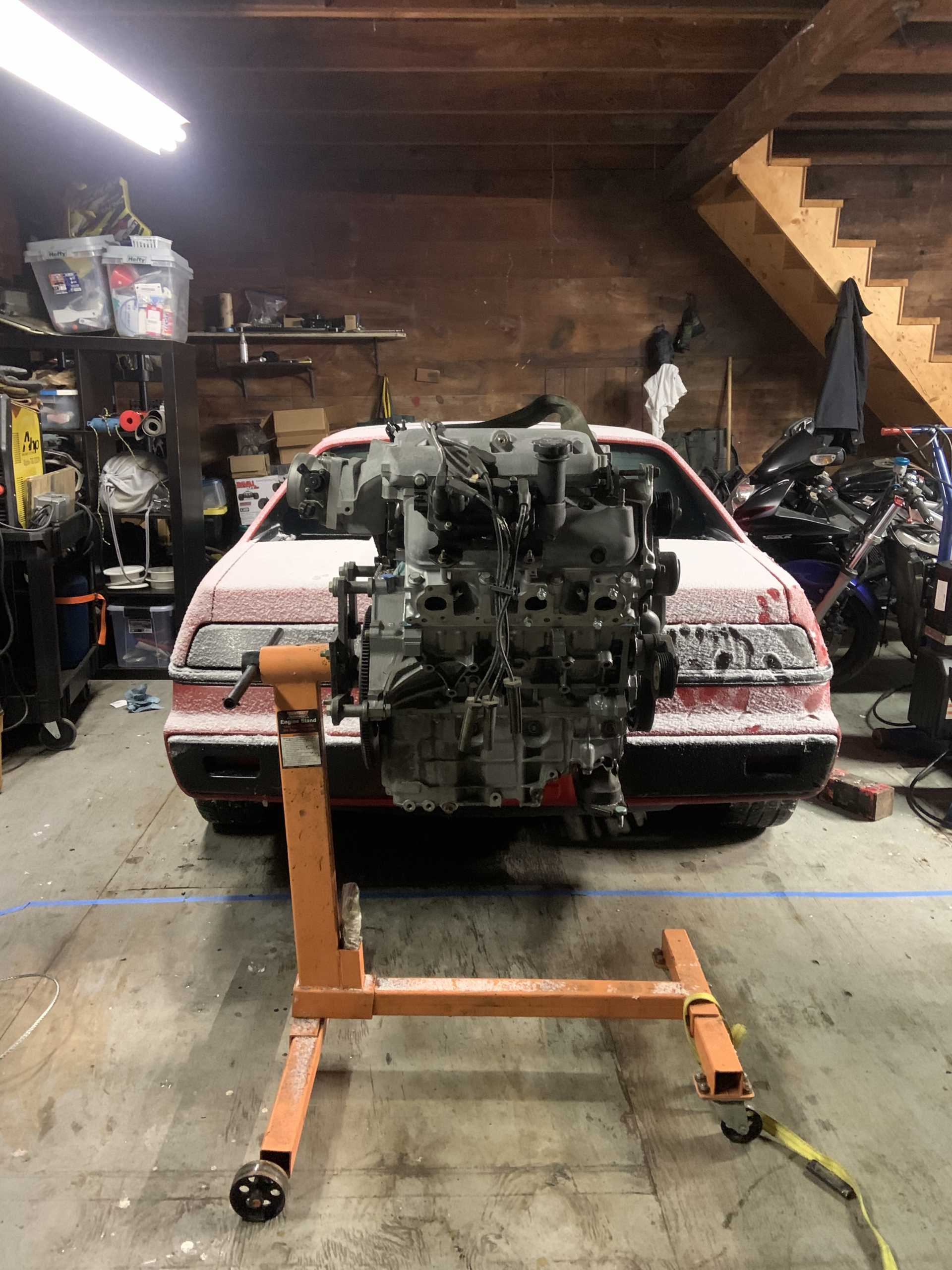
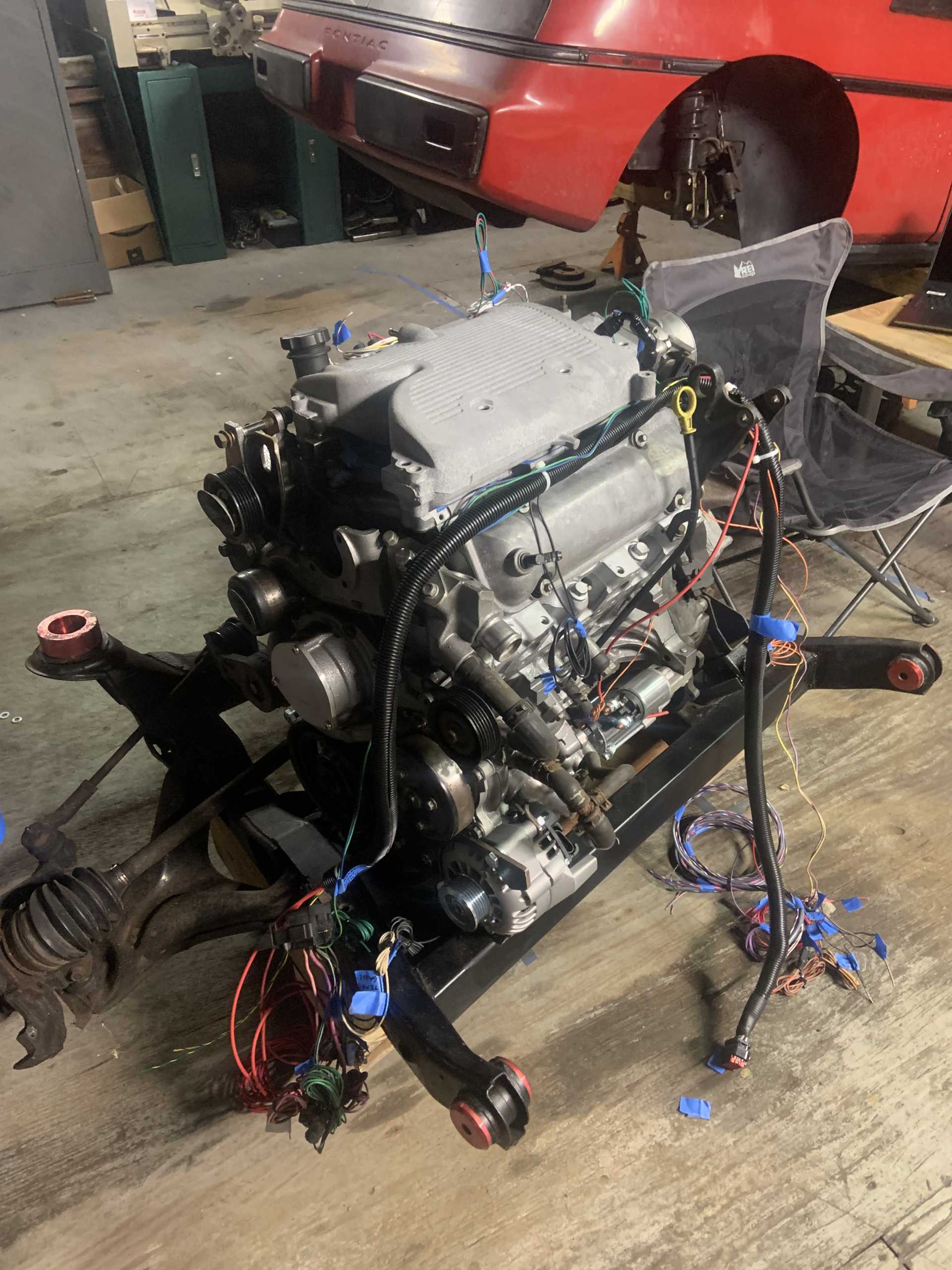
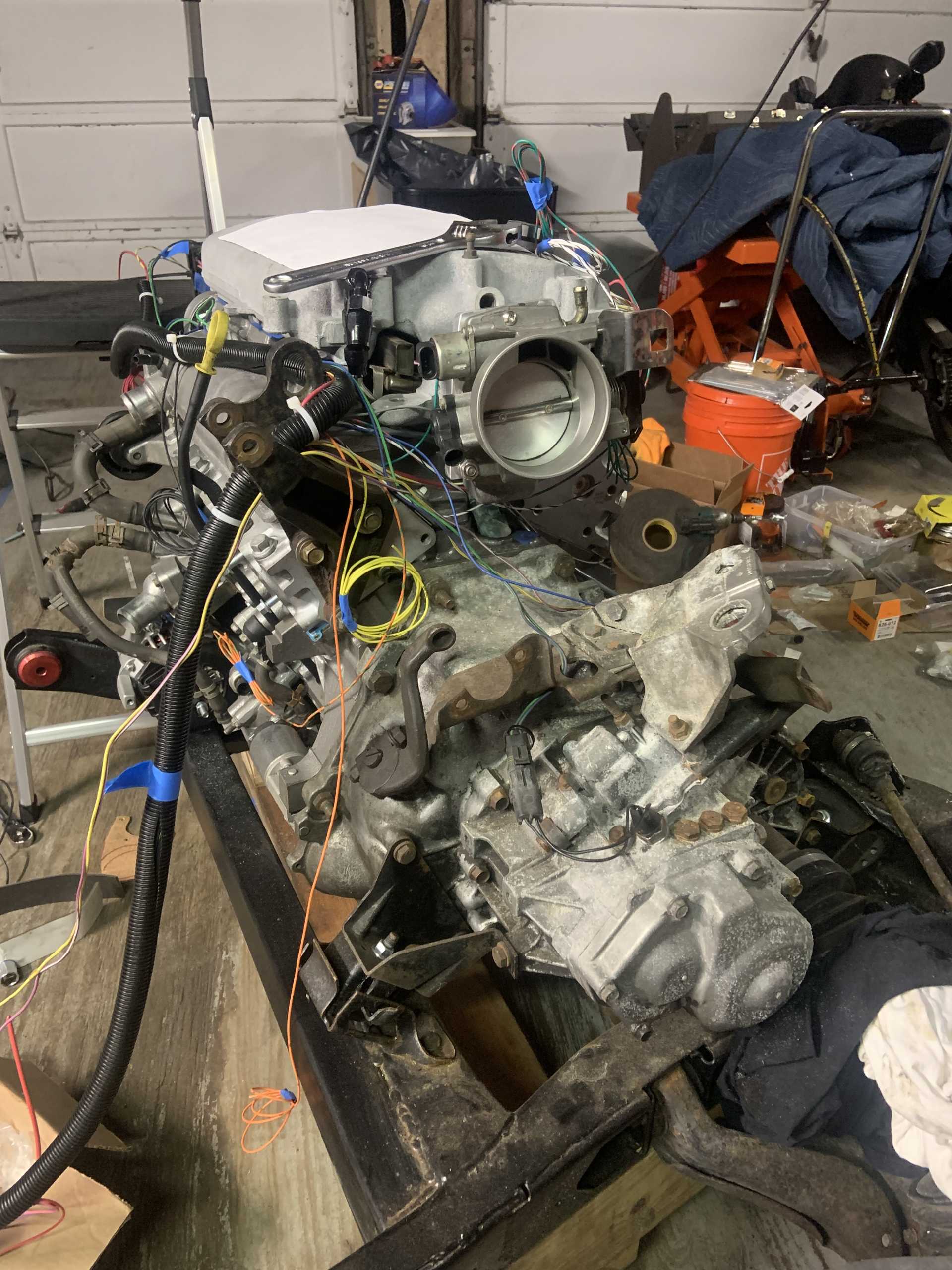
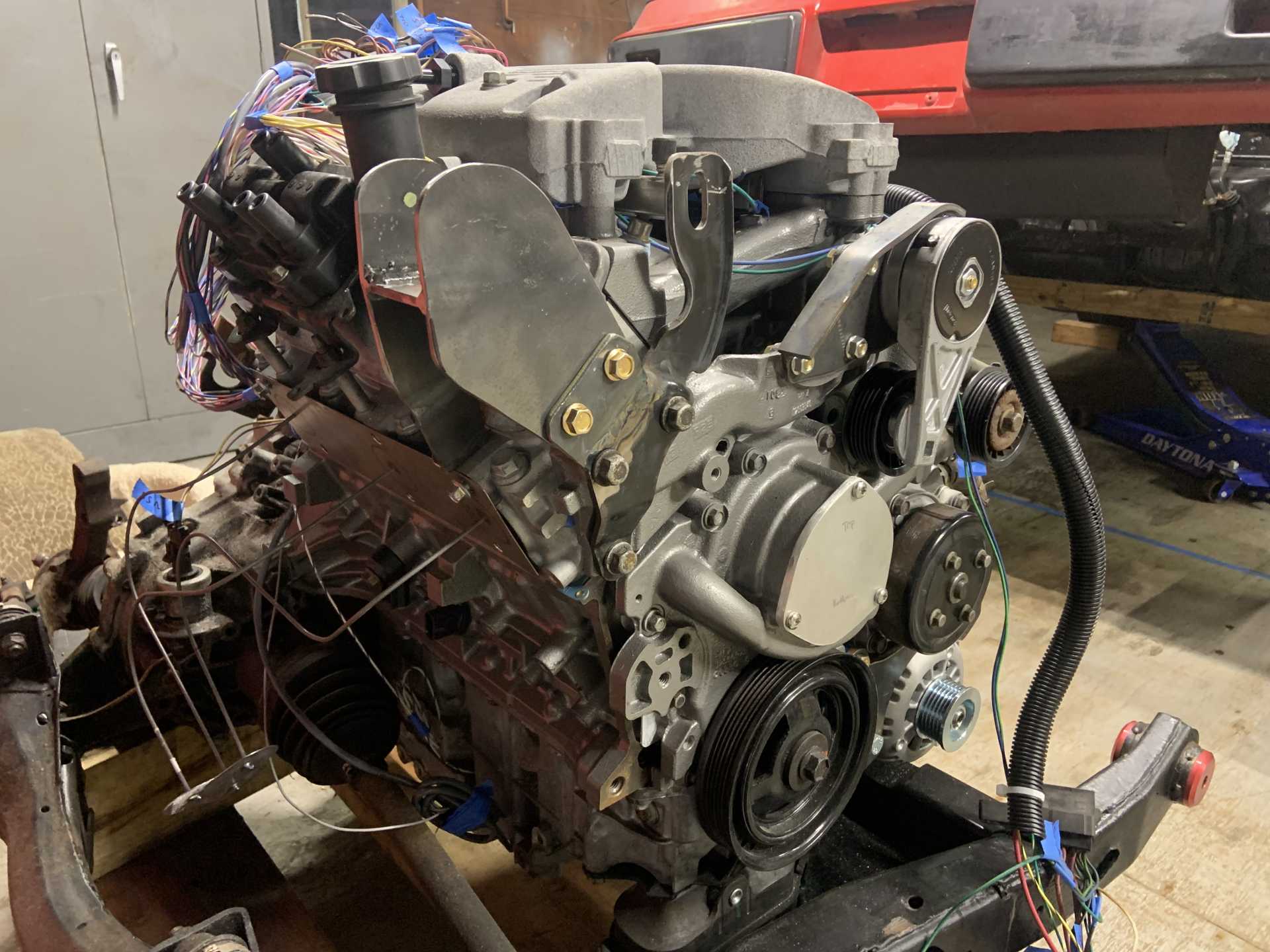
Nice to see the motor in some daylight.
Got the car loaded up with the help of my friend Zig, got a 4 ton come along from Harbor Freight and it made the job of loading and unloading very easy.
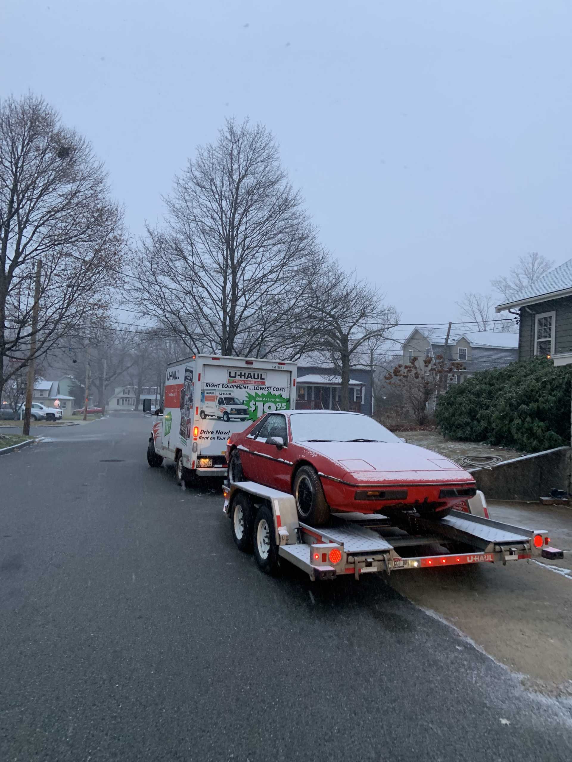
Then it started to snow, saw close to 10 accidents on the highway, the 1:10 trip took over 2 hours.
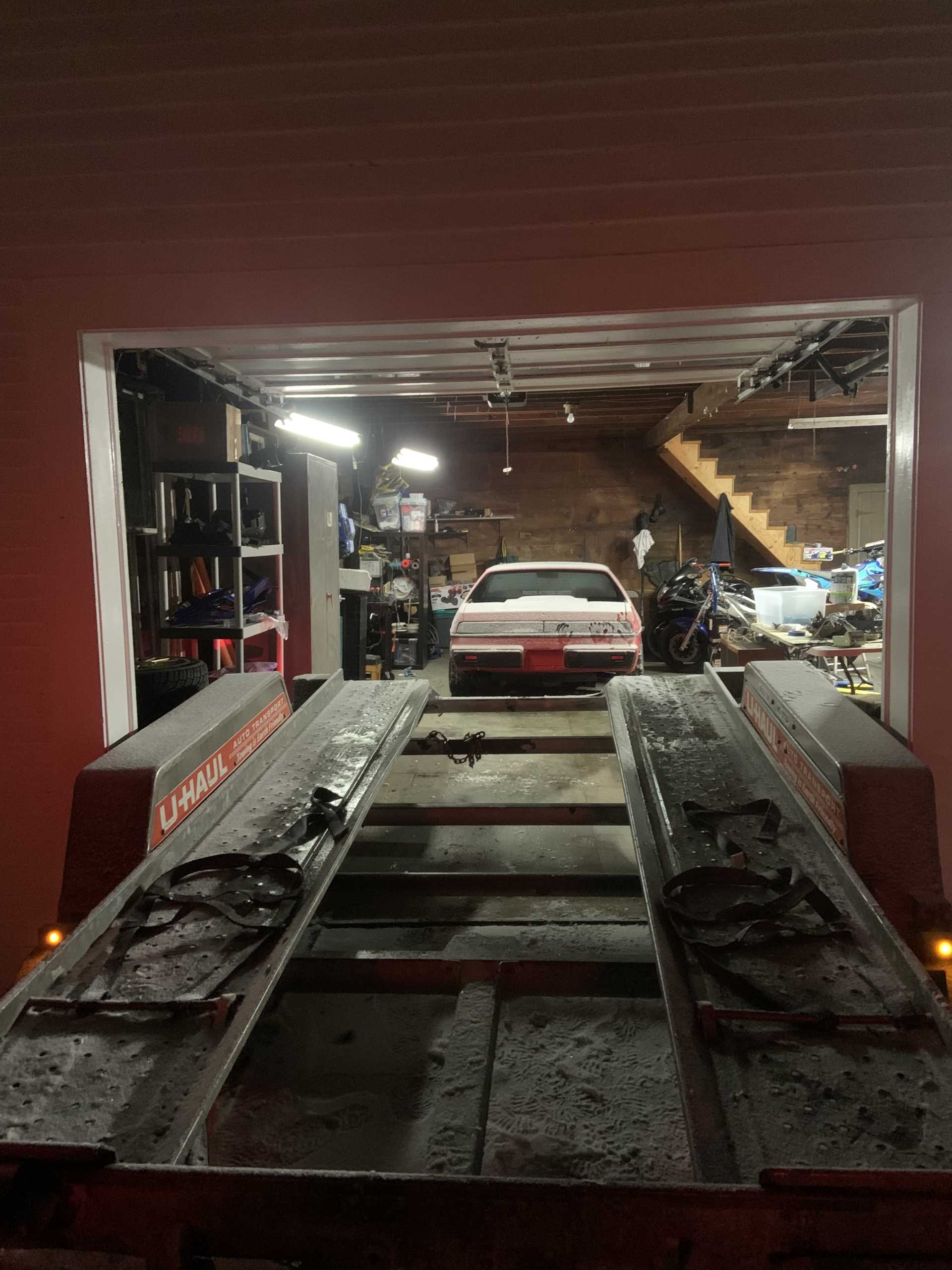
The trailer barely fit through the garage door, maybe an inch and half clearance on each side.
All set in its new house, should get started working on it asap!
[This message has been edited by zkhennings (edited 12-12-2022).]
That's the same one I got! The gear ratio is awesome specially in 3rd and 4th! There is a Quaife limited slip differential available for it, I got one in mine.
[This message has been edited by La fiera (edited 12-14-2022).]
I definitely want to get a Quaife for it, and I hope the engine likes to rev out to take advantage of the shorter gears.
Gotta remember to grab the clutch from my parents house tomorrow, was one of the few things I forgot to grab. Going to put the motor back on the cradle and hopefully keep it there. Might check my pressure plate clearances to the F23 too before mating to the Isuzu so I know if I need to order a new clutch for it. I have a feeling it will fit, seems like most of the SPEC clutches do.
Glad to see you got the car back, any recent updates?
------------------ "I am not what you so glibly call to be a civilized man. I have broken with society for reasons which I alone am able to appreciate. I am therefore not subject to it's stupid laws, and I ask you to never allude to them in my presence again."
I invited Lou Dias to trash me in my own thread, he refused. sorry. if he trashes your thread going after me. I tried.
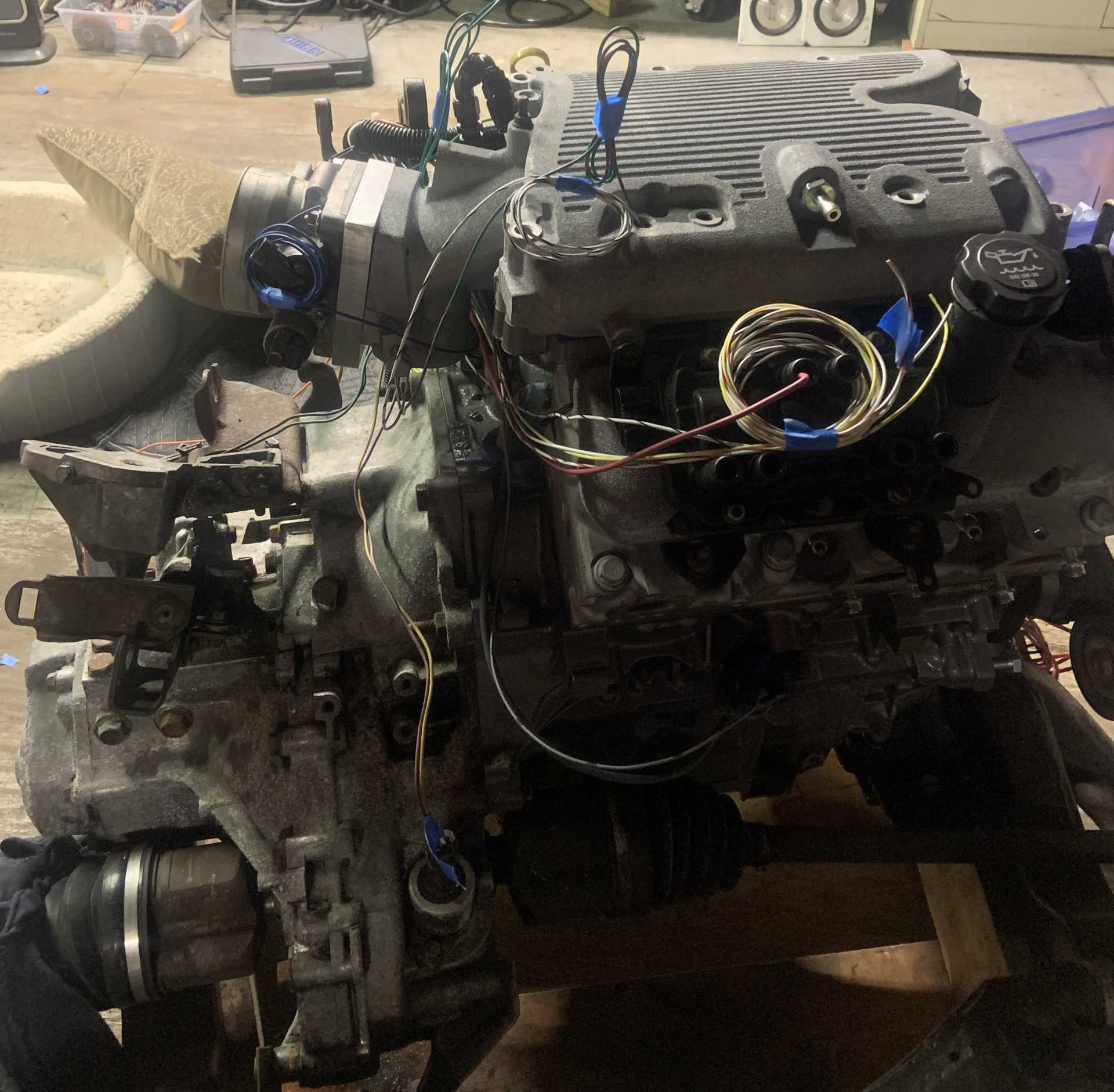
Indeed, I had to spend a lot of time organizing the barn and getting stuff out of there that wasn’t necessary and I designed some shelving and whatnot that I have yet to build. I also got a heating solution set up and got some propane tanks to run it. And then I started doing some work on the car. I pulled the subframe out, cleaned up the flywheel on the motor as it had gotten some surface rust, cleaned and remounted the clutch, got the throwout bearing installed and mated the engine and trans for what should be the last time.
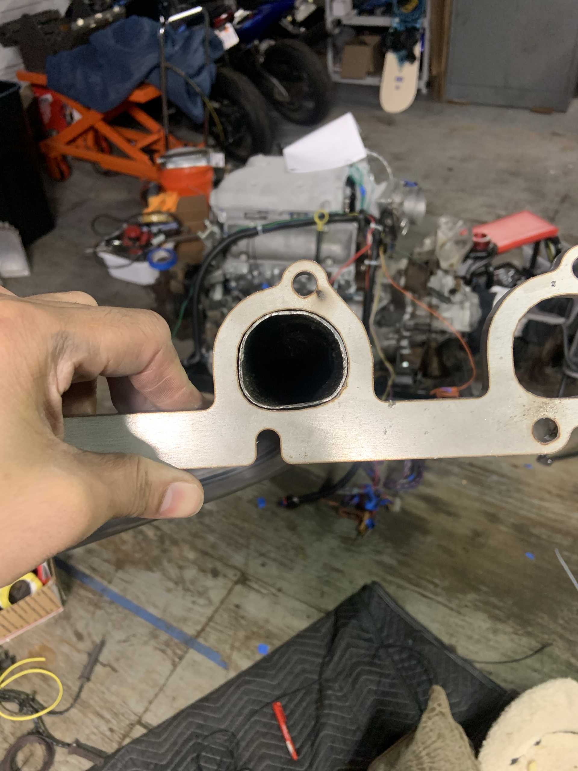
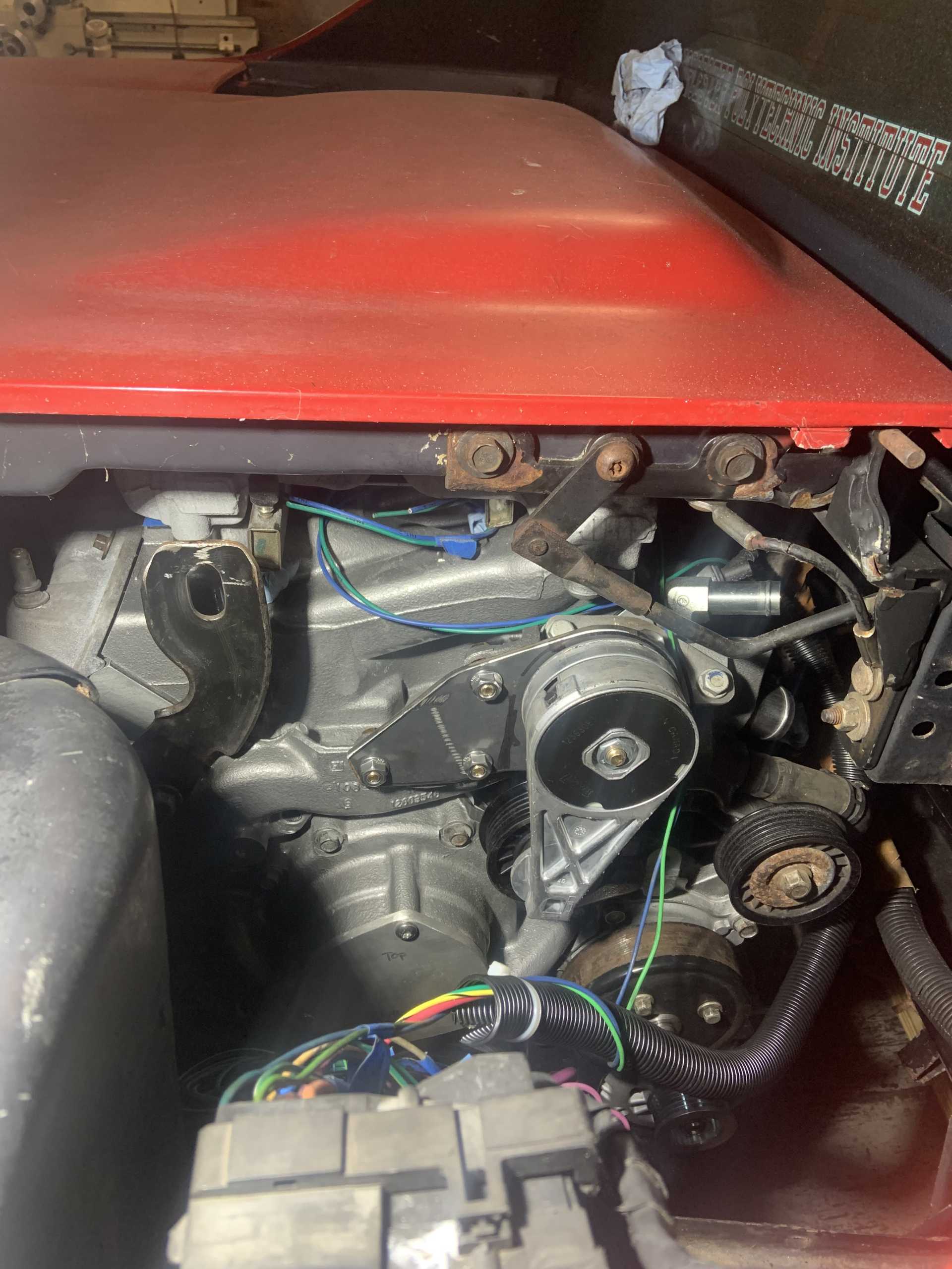
I then spent time planning what I want to do with alternator, exhaust, and fuel lines. For the exhaust I have decided to have the manifolds point towards the front of the motor instead of having a crossover over the transmission like I had been planning. I am going to notch the new crossmember and have the exhaust pass between the oil pan and motor mount, and it will have a Y right before the cradle hump that allows the exhaust to exit to the muffler. This should allow me to make better headers that will be easier to fabricate, get the exhaust away from the shifter cables, and it will make it really easy to remove from below.
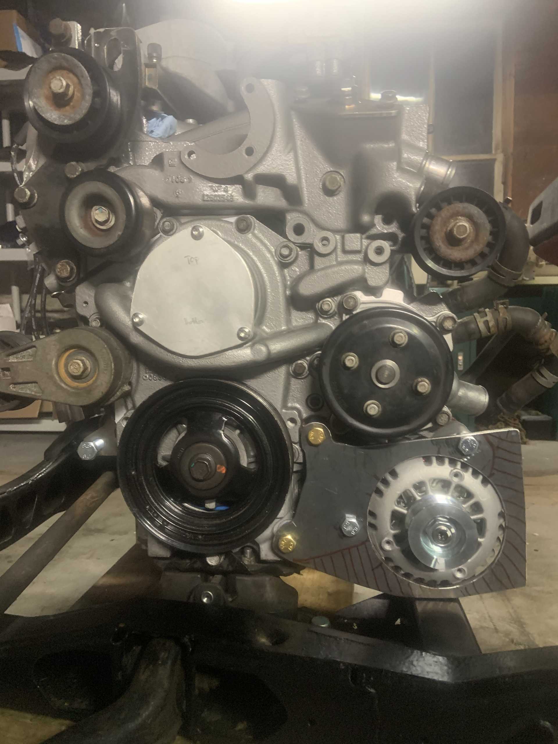
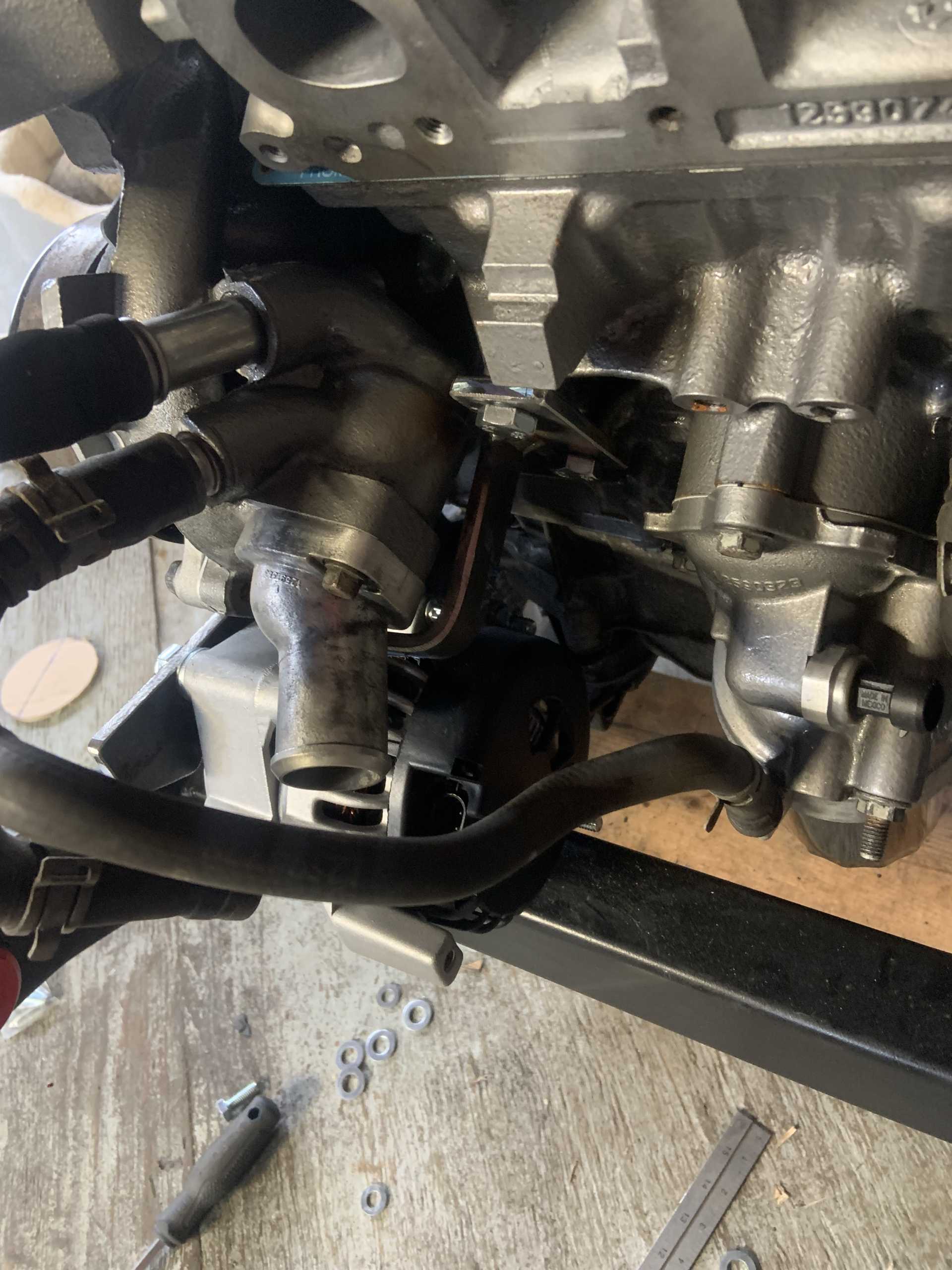
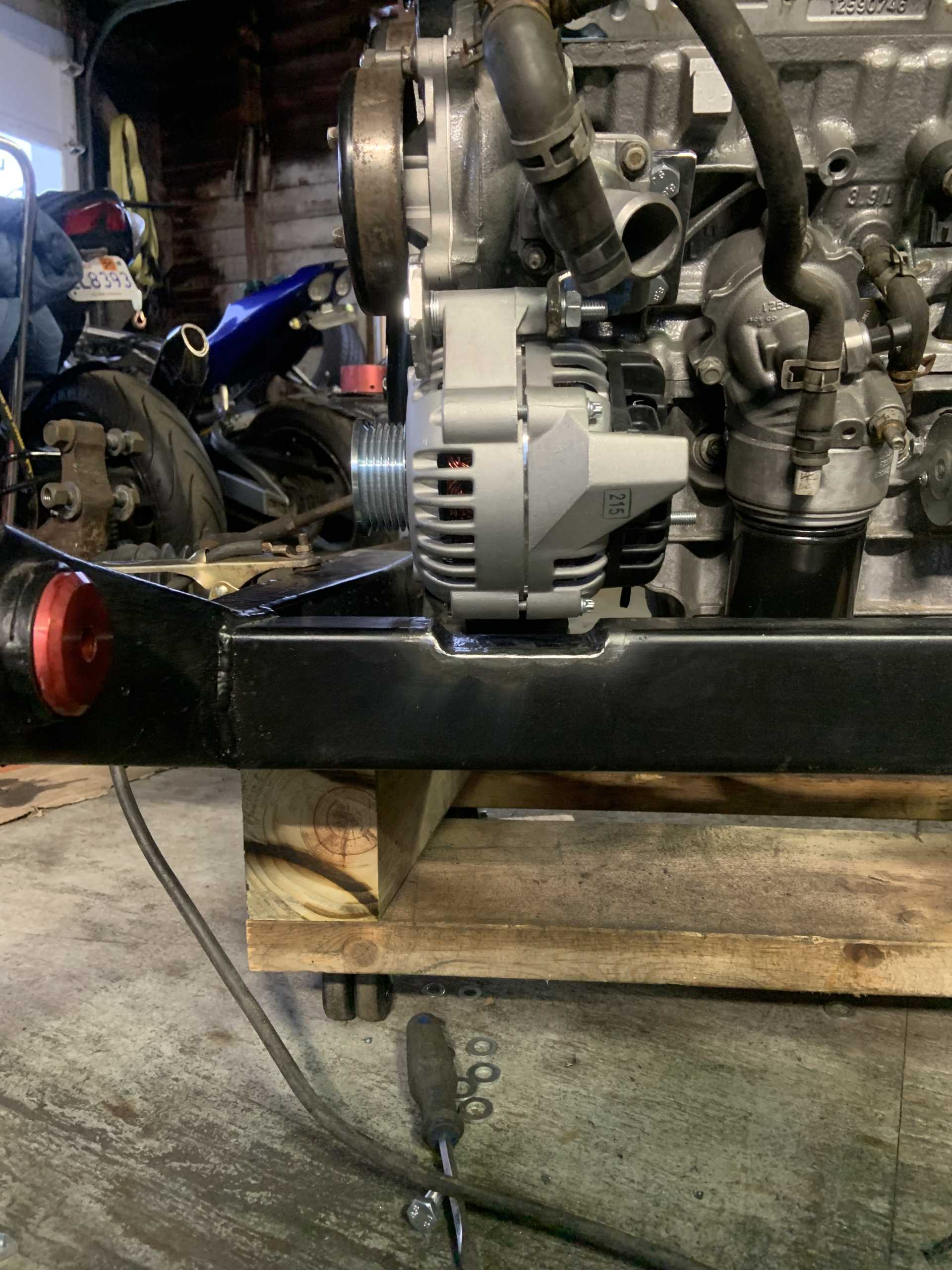
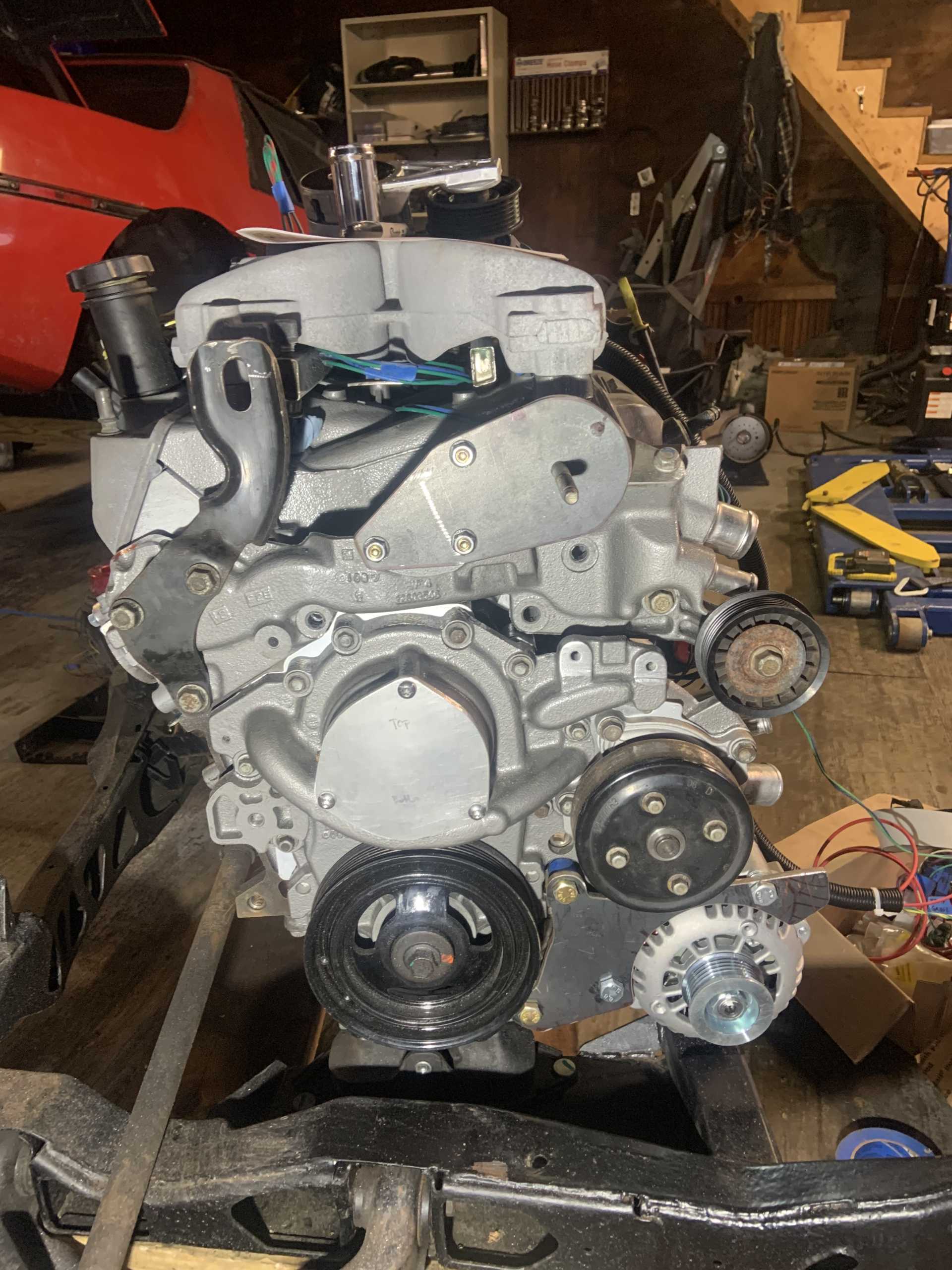
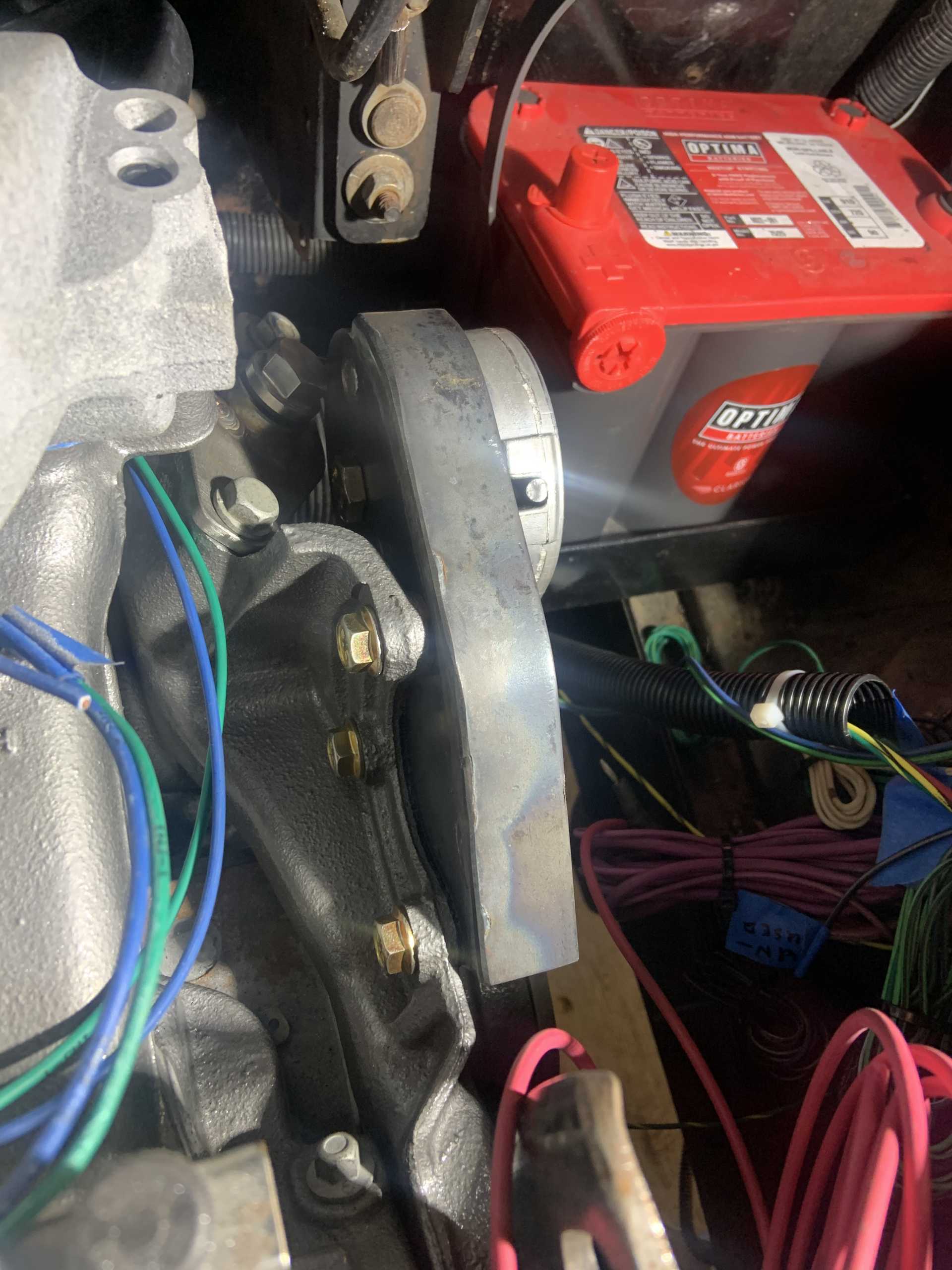
For the alternator I ended up deciding it will go where I have been planning, under the water pump.
I have decided to run the fuel pressure regulator to the drivers side hinge box area, which will make a much shorter run of braided line to get to the fuel rail. Since the exhaust is not going to be over there anymore, it makes much more sense to put it closer to the fuel rail input. It’s much less busy over there.
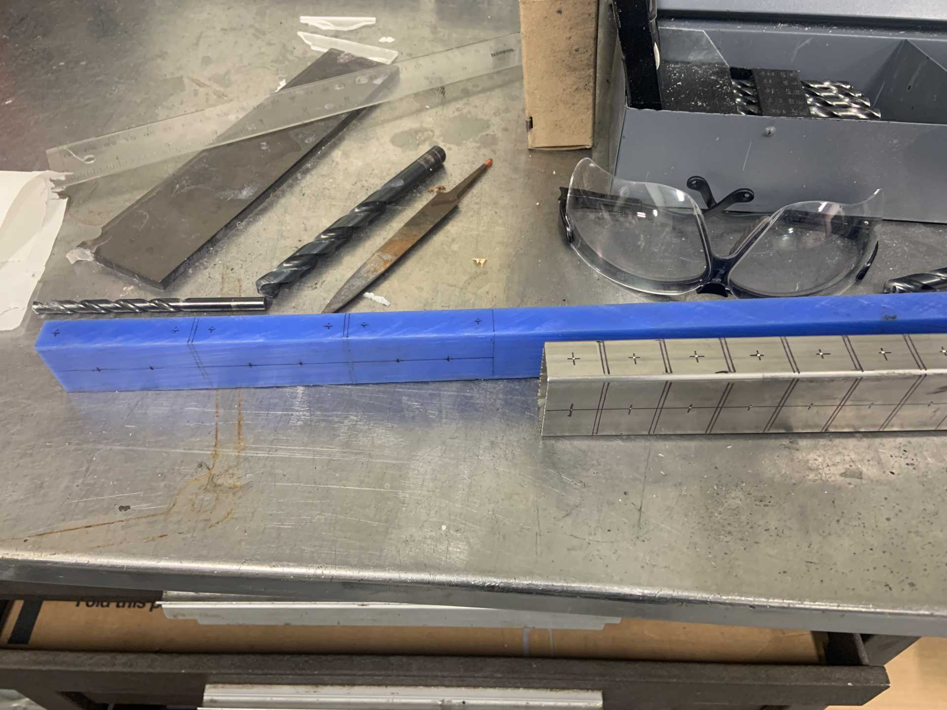
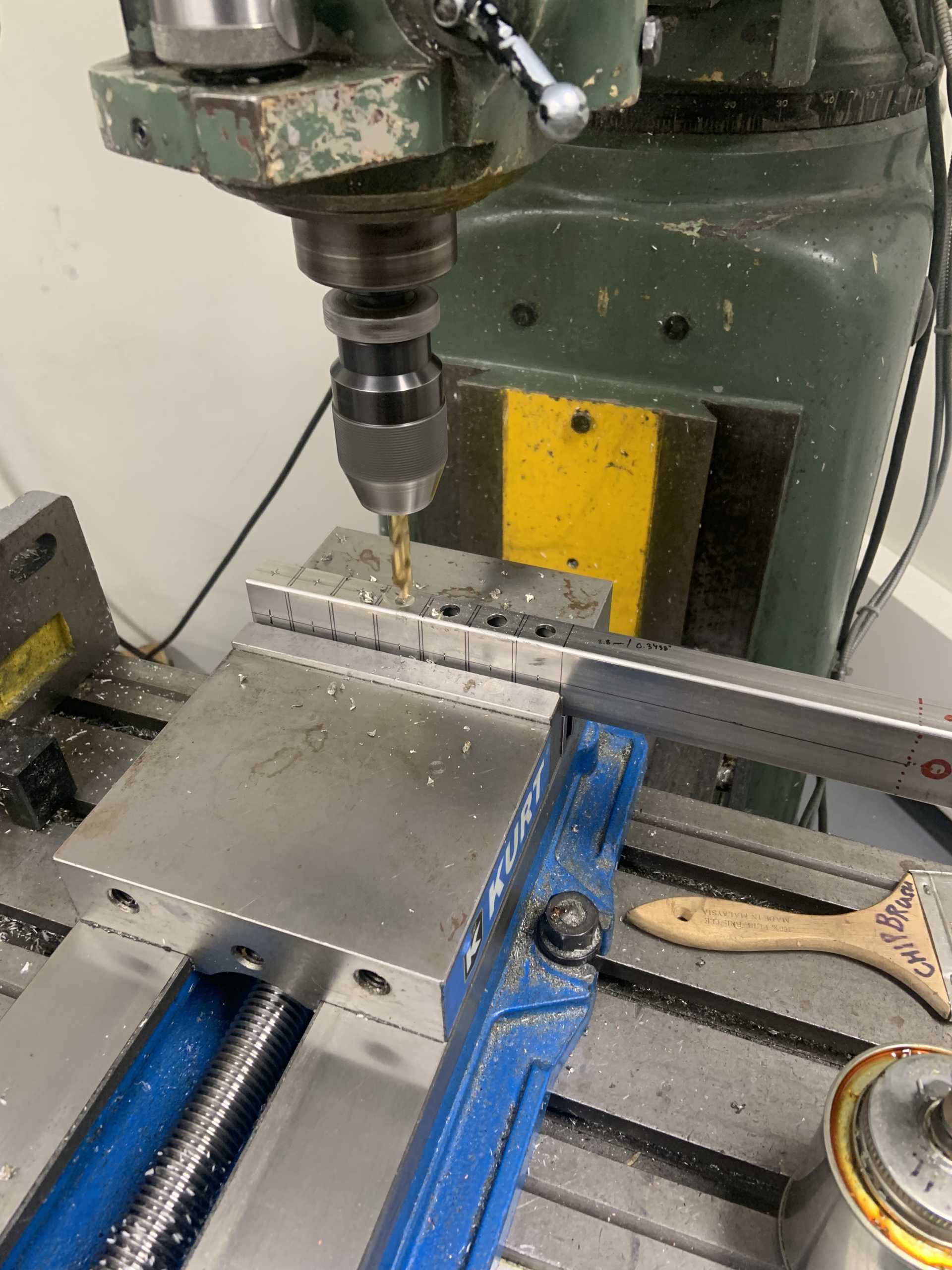
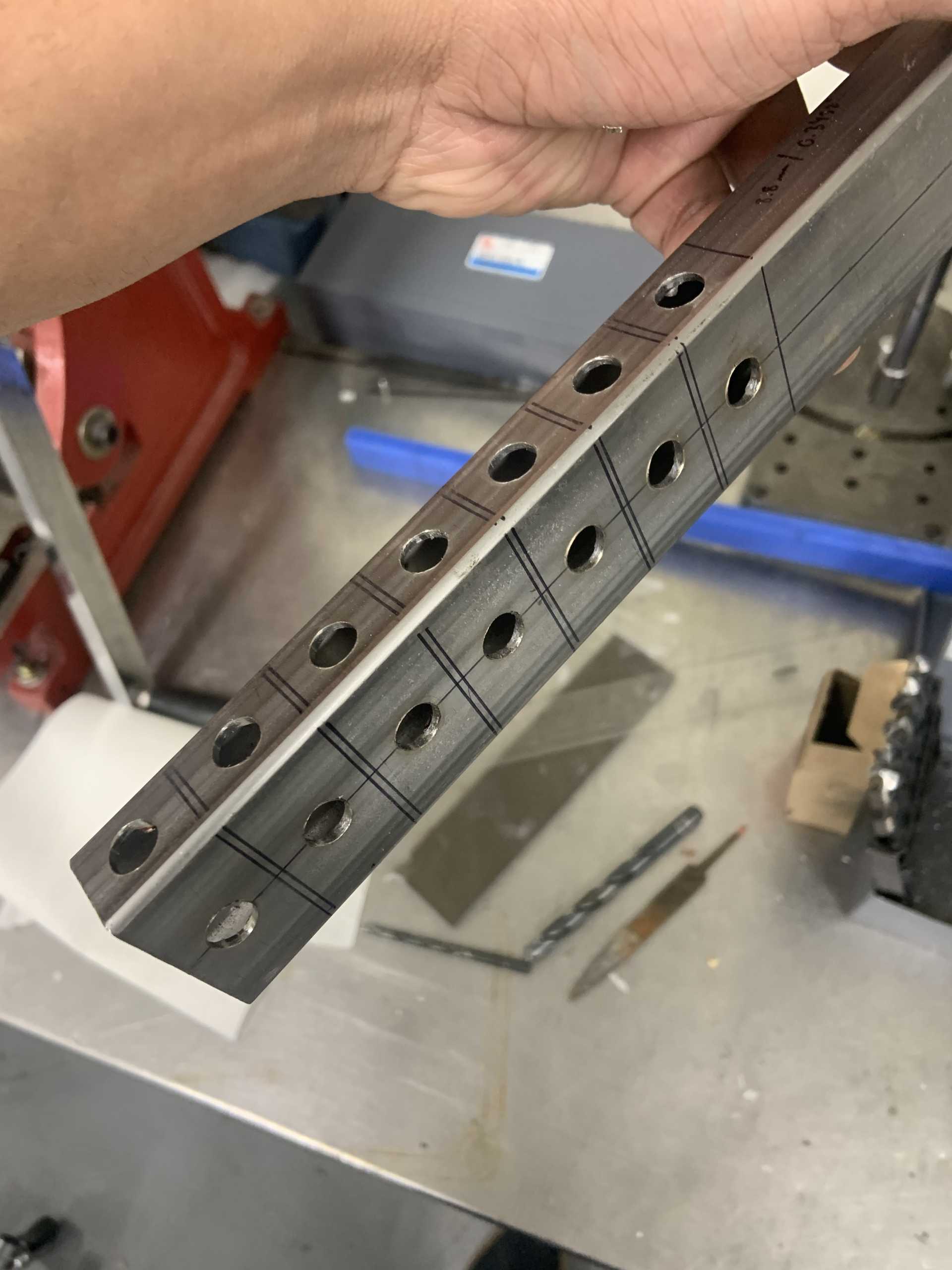
I bought some 1/4” metal for the alternator bracket and working on that next.
I have also been doing some research to try and figure out a ballpark hp number for this thing. These LZ9 heads have really good flow, with my cam and the 1.7 ratio rockers, it will have almost 0.600" of lift on the intake and a little less than that on the exhaust side of things. Combine that with the port work (especially in the intake and exhaust bowls) and I think I should have very good flow, maybe even close to 300cfm on the intake side. Combined with some good headers I think I could realistically see 300+whp, and I will definitely get it on a dyno to find out. Also want to get a 1/4 mile time on the list and maybe take the spot for fastest NA V6 (or at least fastest NA pushrod 60* V6)
Something else I want to explore is upgrading the trunions in the LZ9 rocker arms, currently needle bearings, these are known to fail in the similarly designed LS motors, especially with higher RPMs. I am very curious if they could be rebuilt with brass bushing trunions for LS rocker arms. With all the other LS components that have fit this motor, I would imagine that they will work, but I am not sure if the OD of the trunion will match the LZ9 pedestal. I may have to get a spare rocker arm and see if I can buy a single trunion upgrade to figure out feasibility. I did some searching but came up with nothing.
[This message has been edited by zkhennings (edited 01-02-2023).]
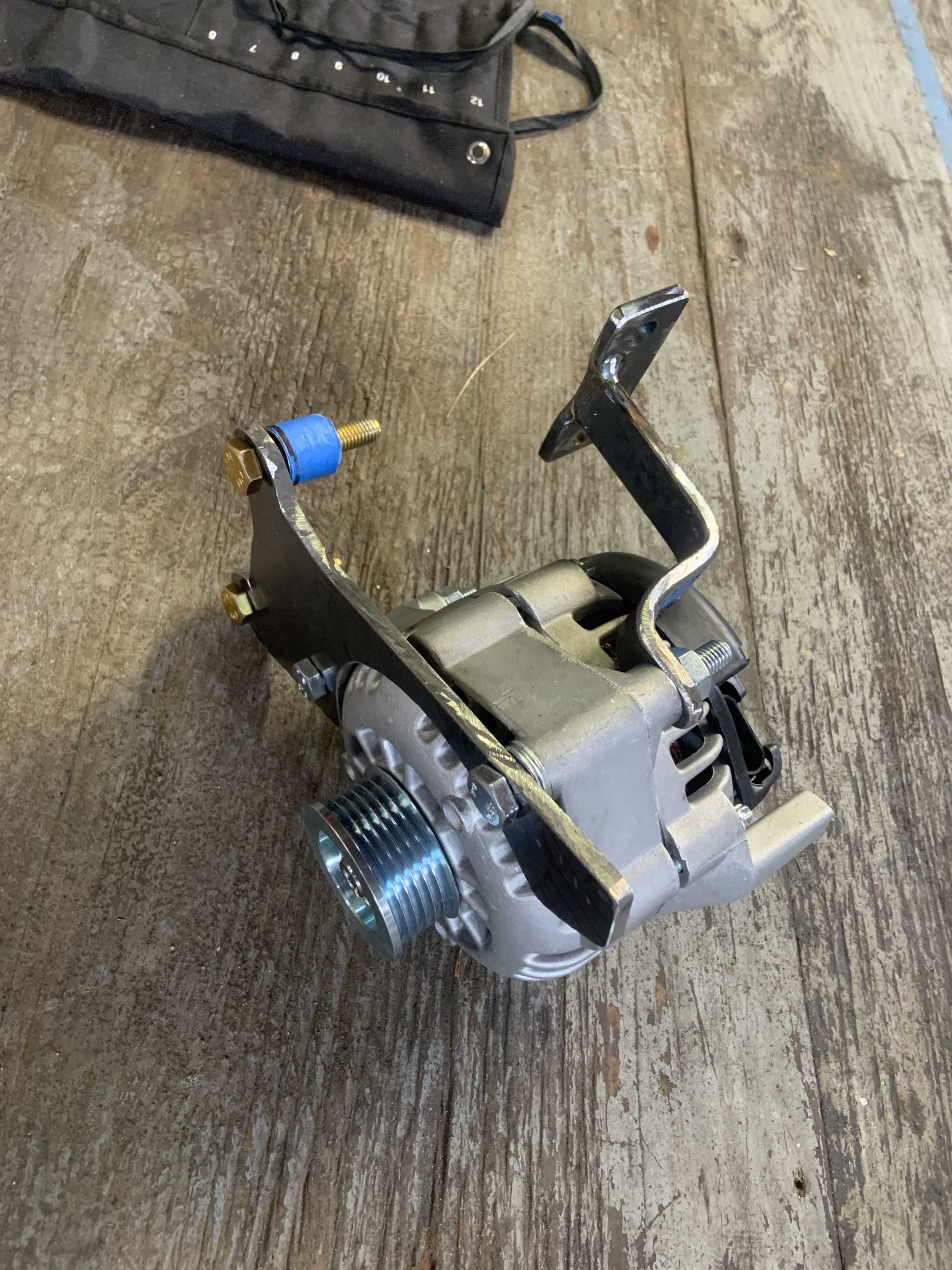
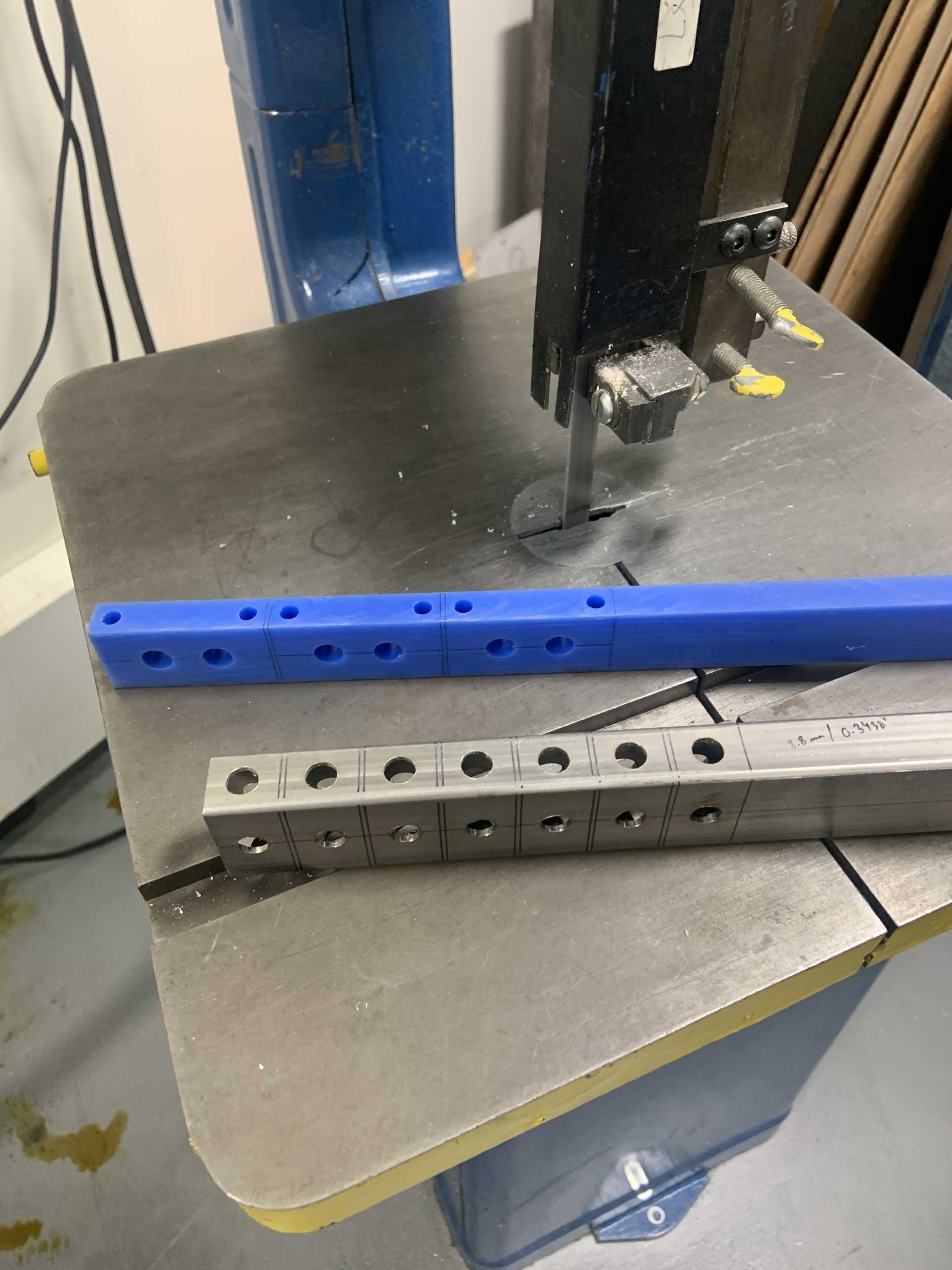
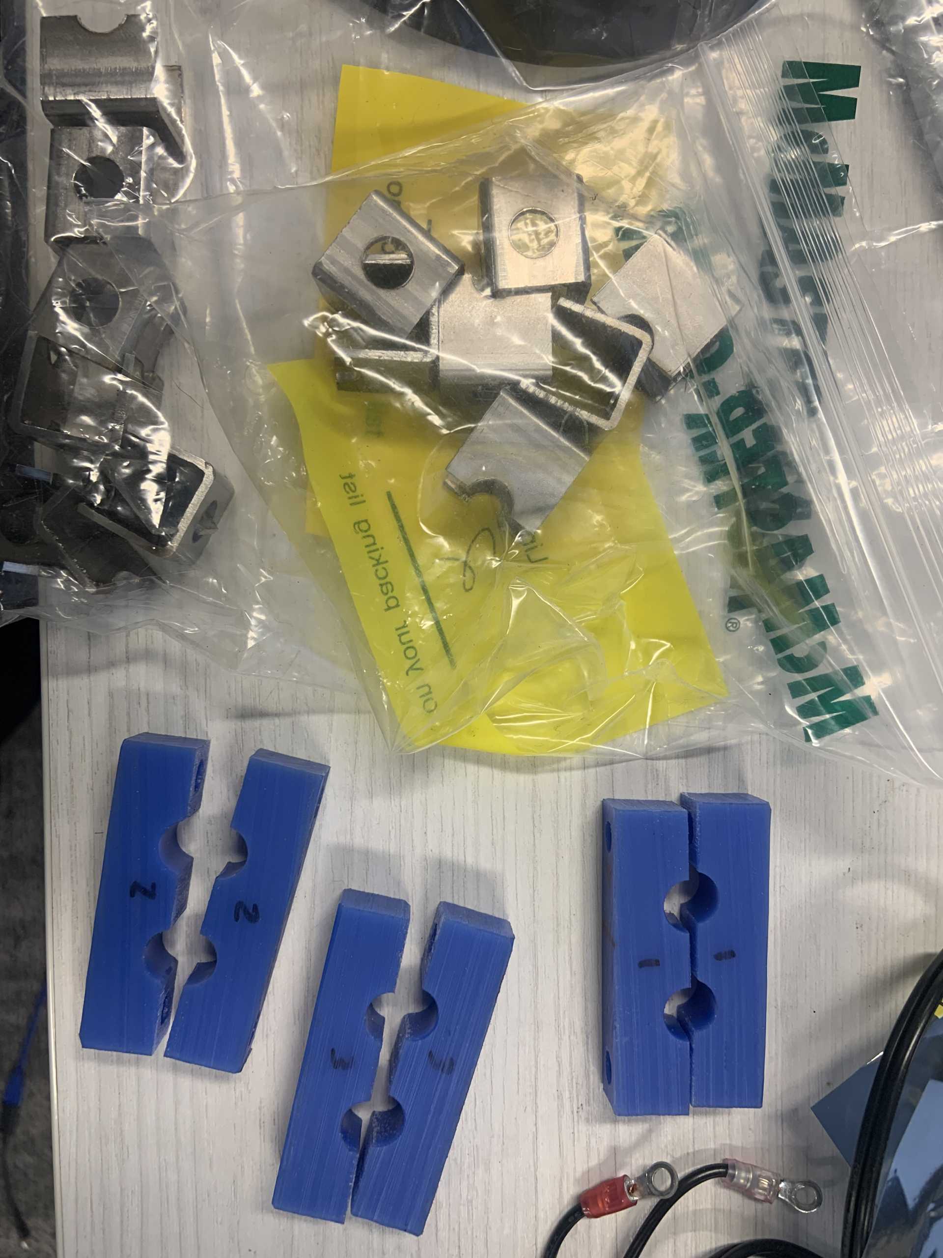
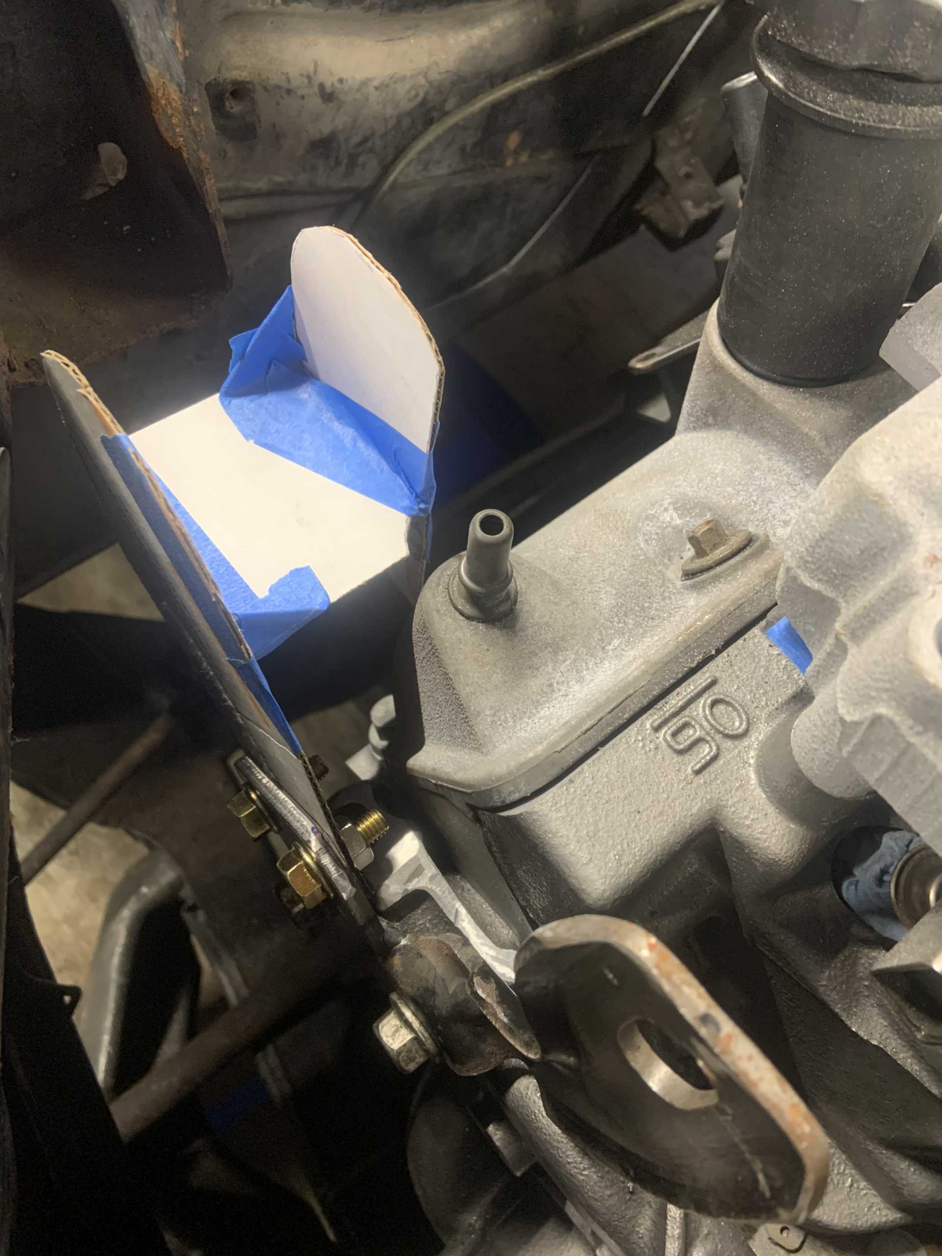
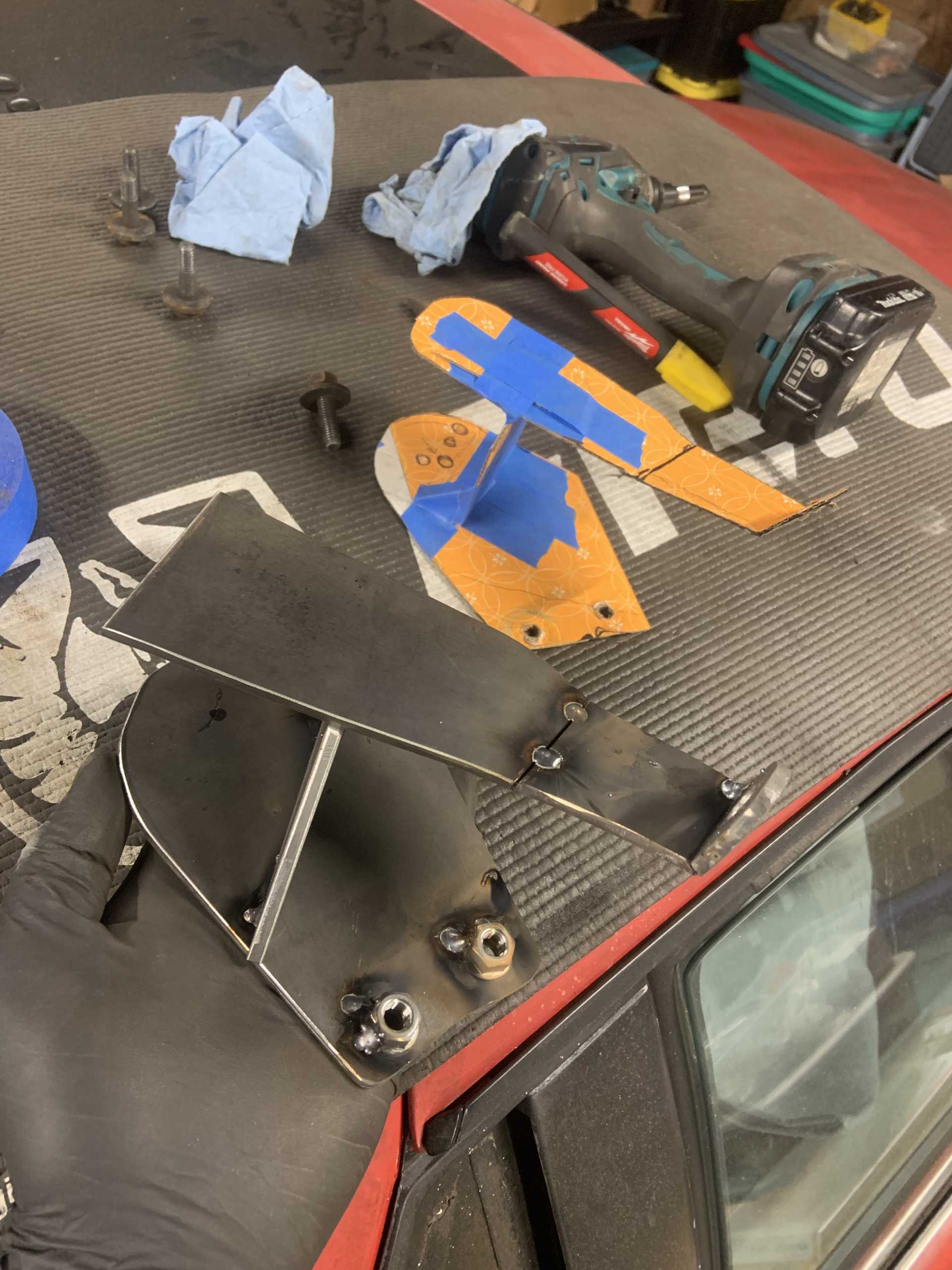
Did "CAD" to rough out a shape, cut the large circular hole with a jig saw, took forever. I left the bracket as large as possible first to help me figure out all my possibilities.
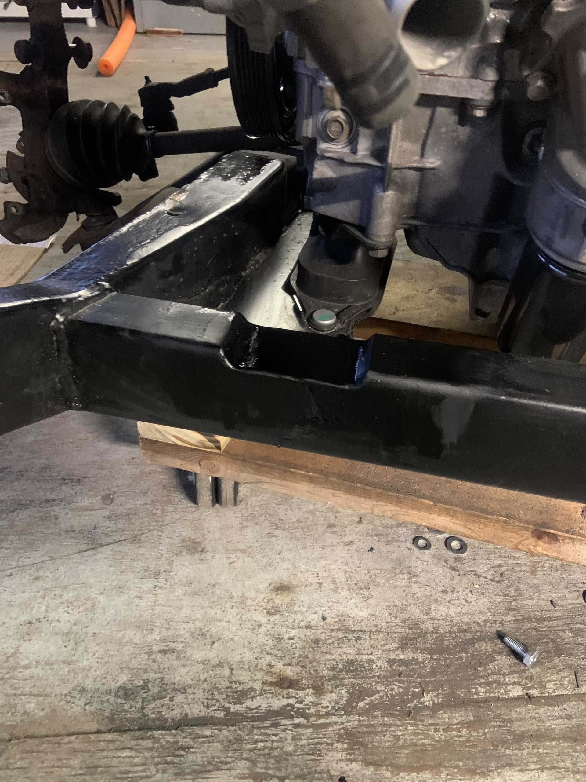
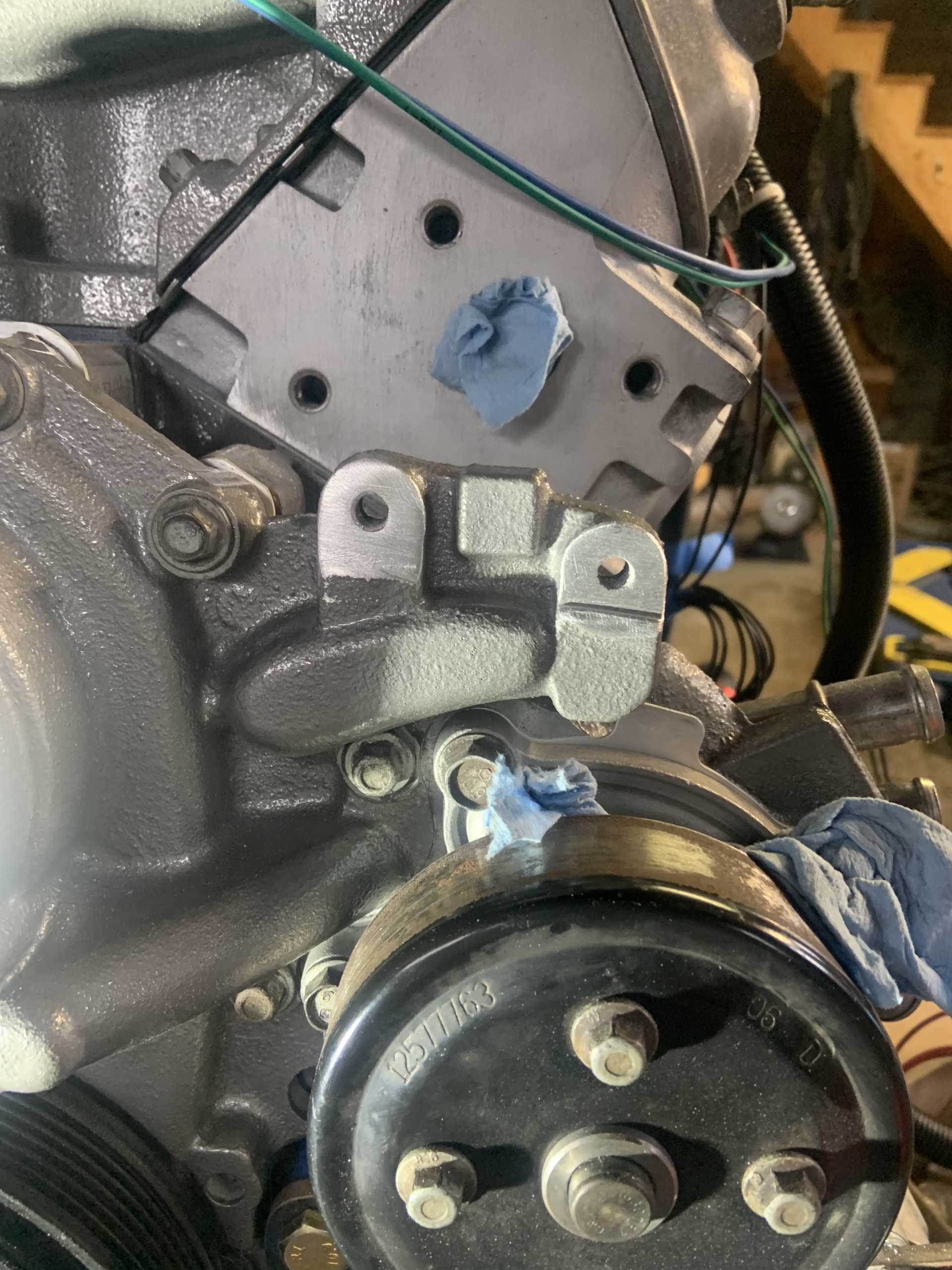
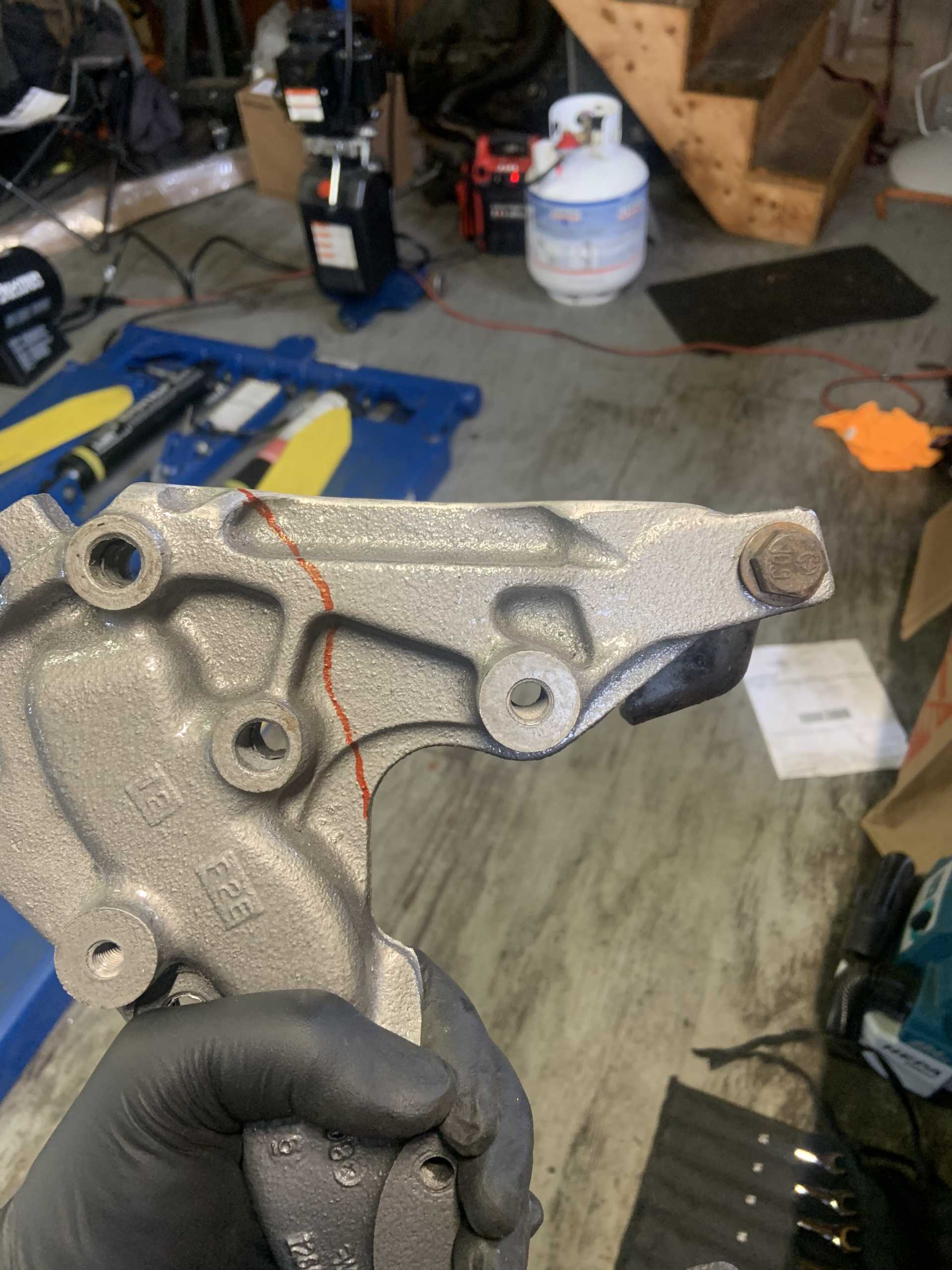
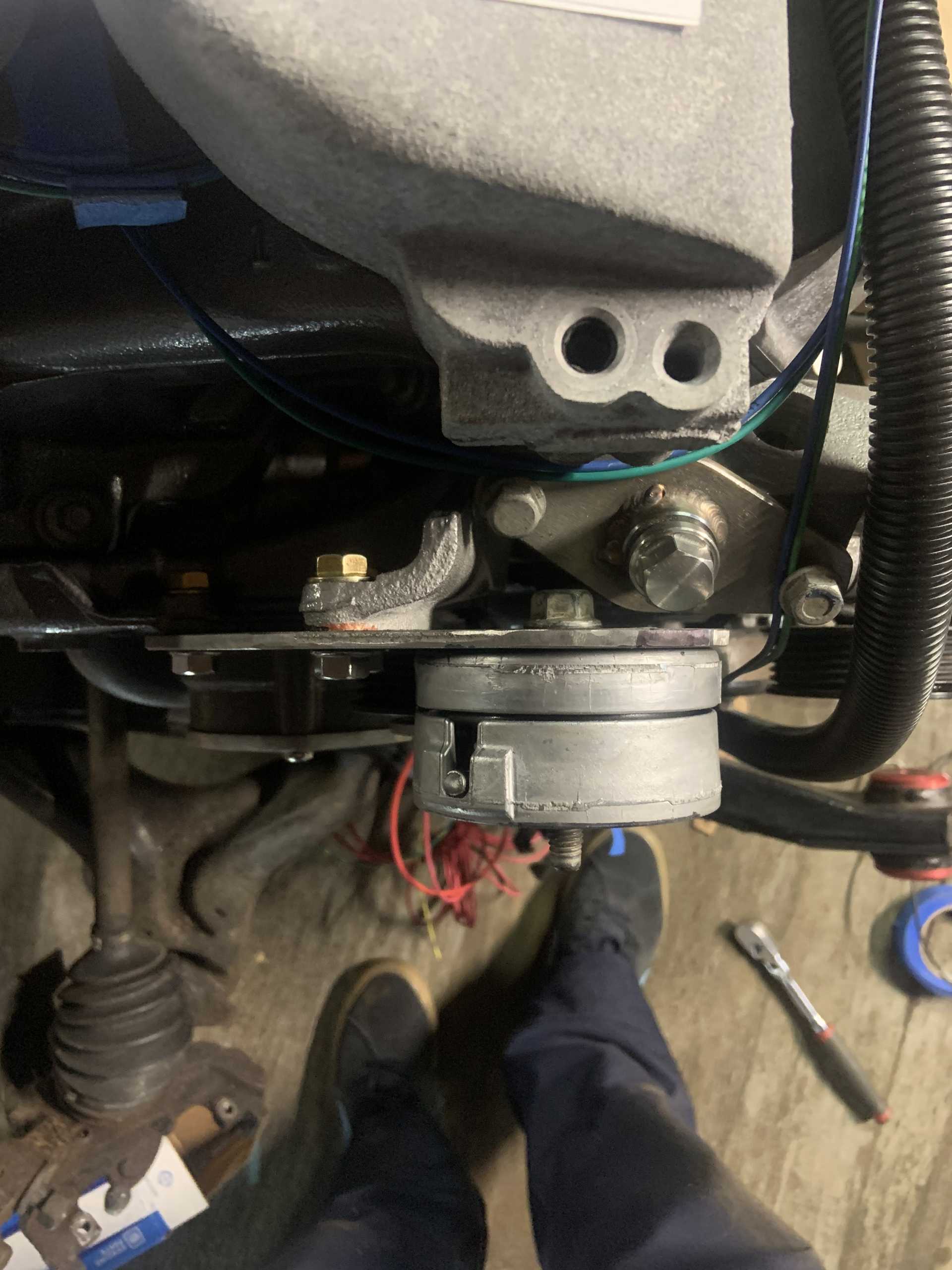
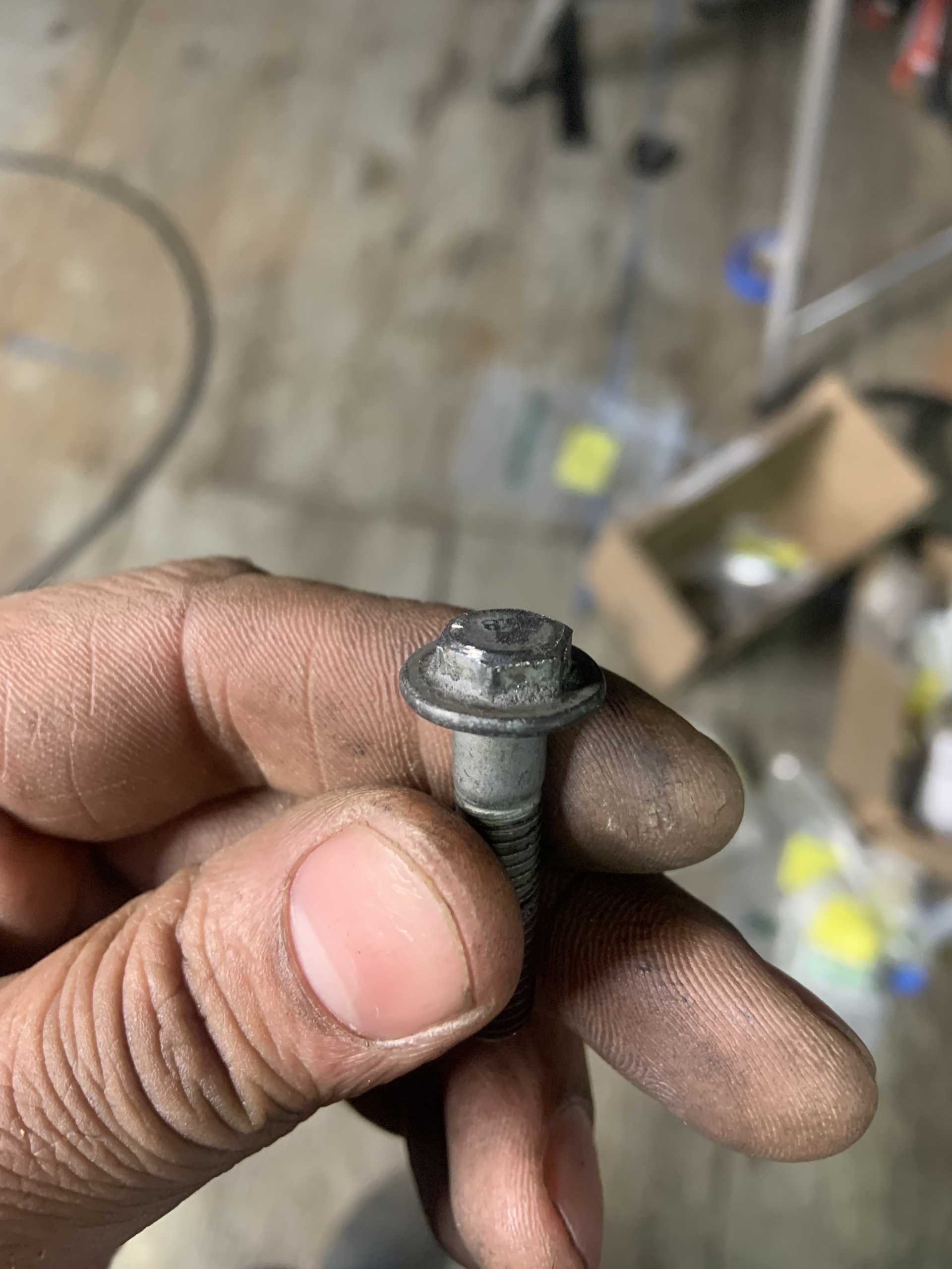
Just using a ton of washers right now to get the spacing correct for the alternator, the two bolt holes I am tying into on the block/oil pan are originally for the AC compressor. I thought they were in the same plane but they are not, the threaded hole in the oil pan is deeper than the hole in the block. I have it spaced out by 2 additional washers right now, but I am going to have to come up with a way to measure the difference precisely.
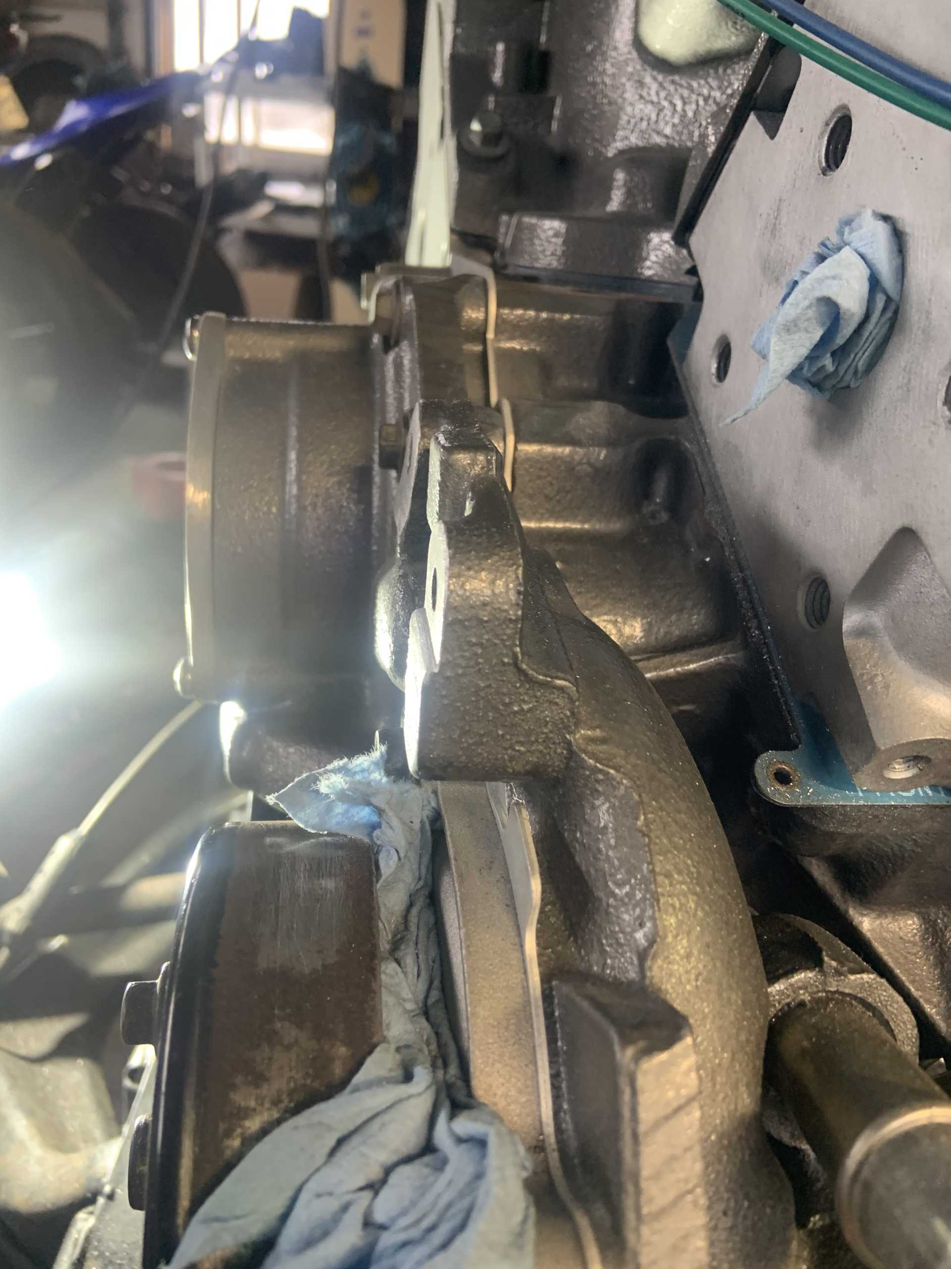
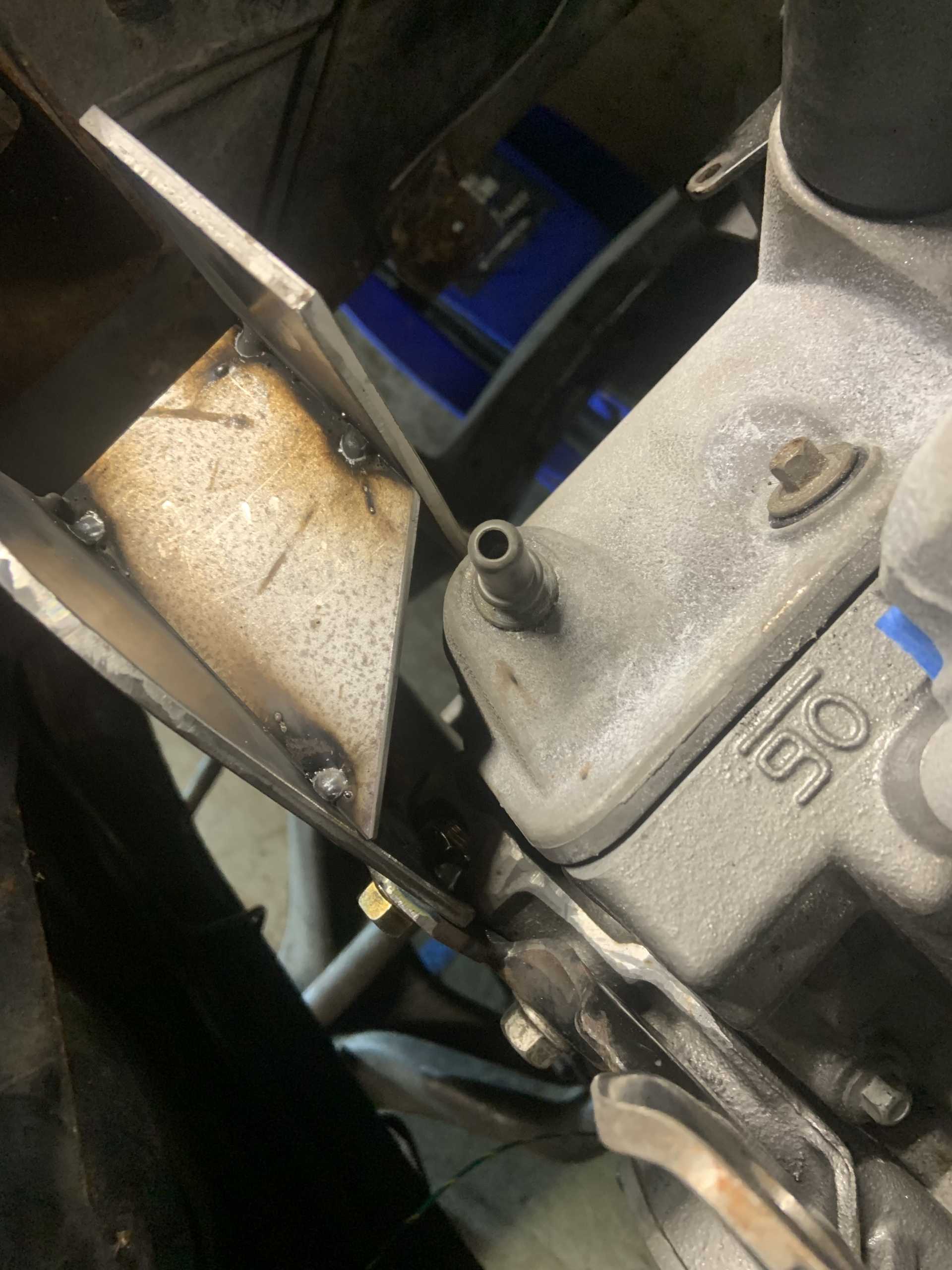
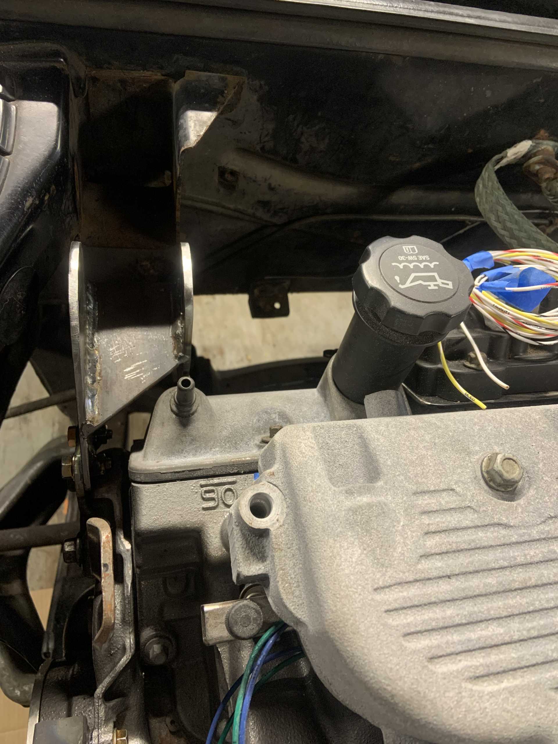
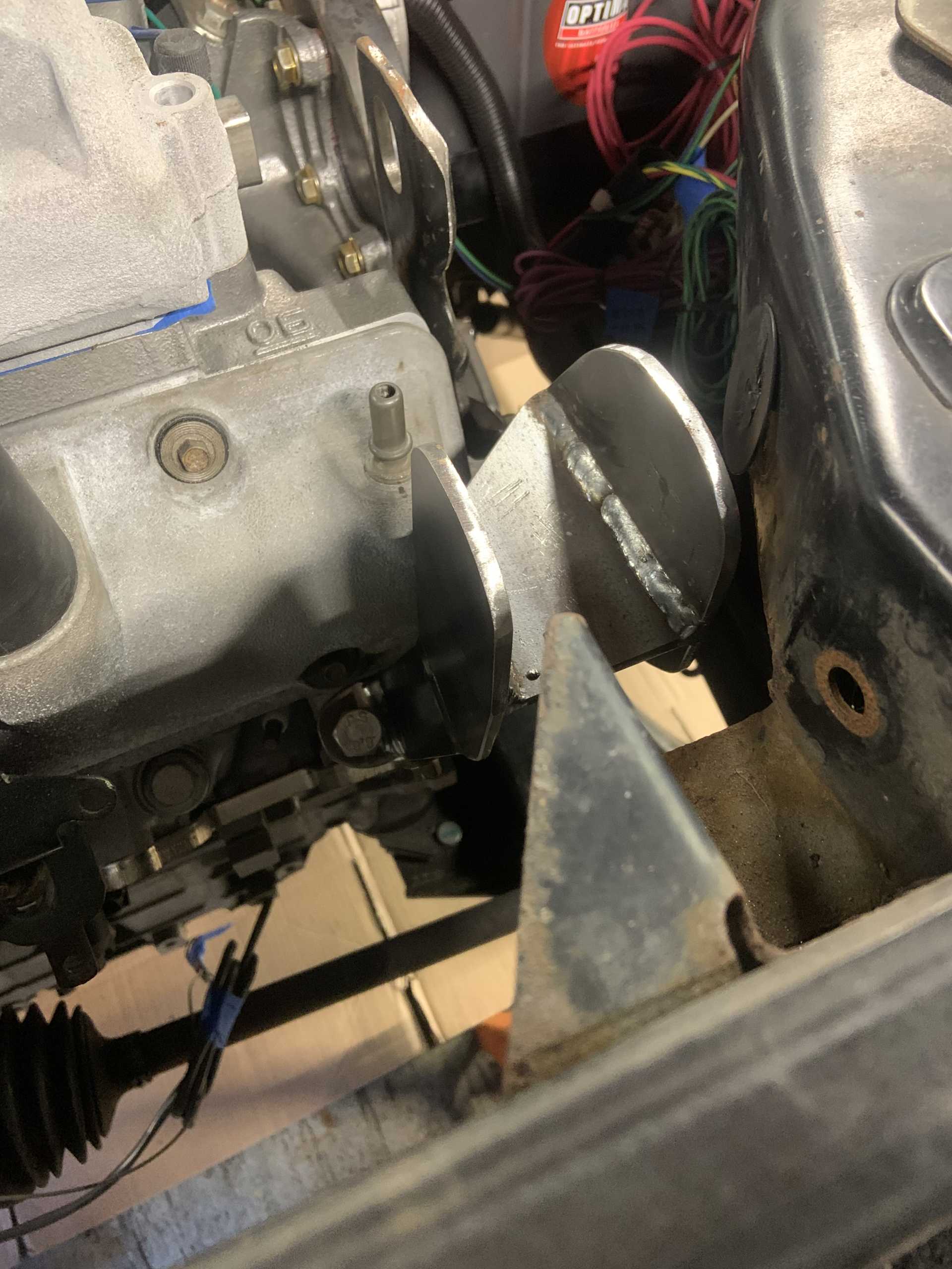
Not enough clearance to the crossmember for my liking. Engine will only pitch this direction mainly in engine braking, but I don't want them to hit.
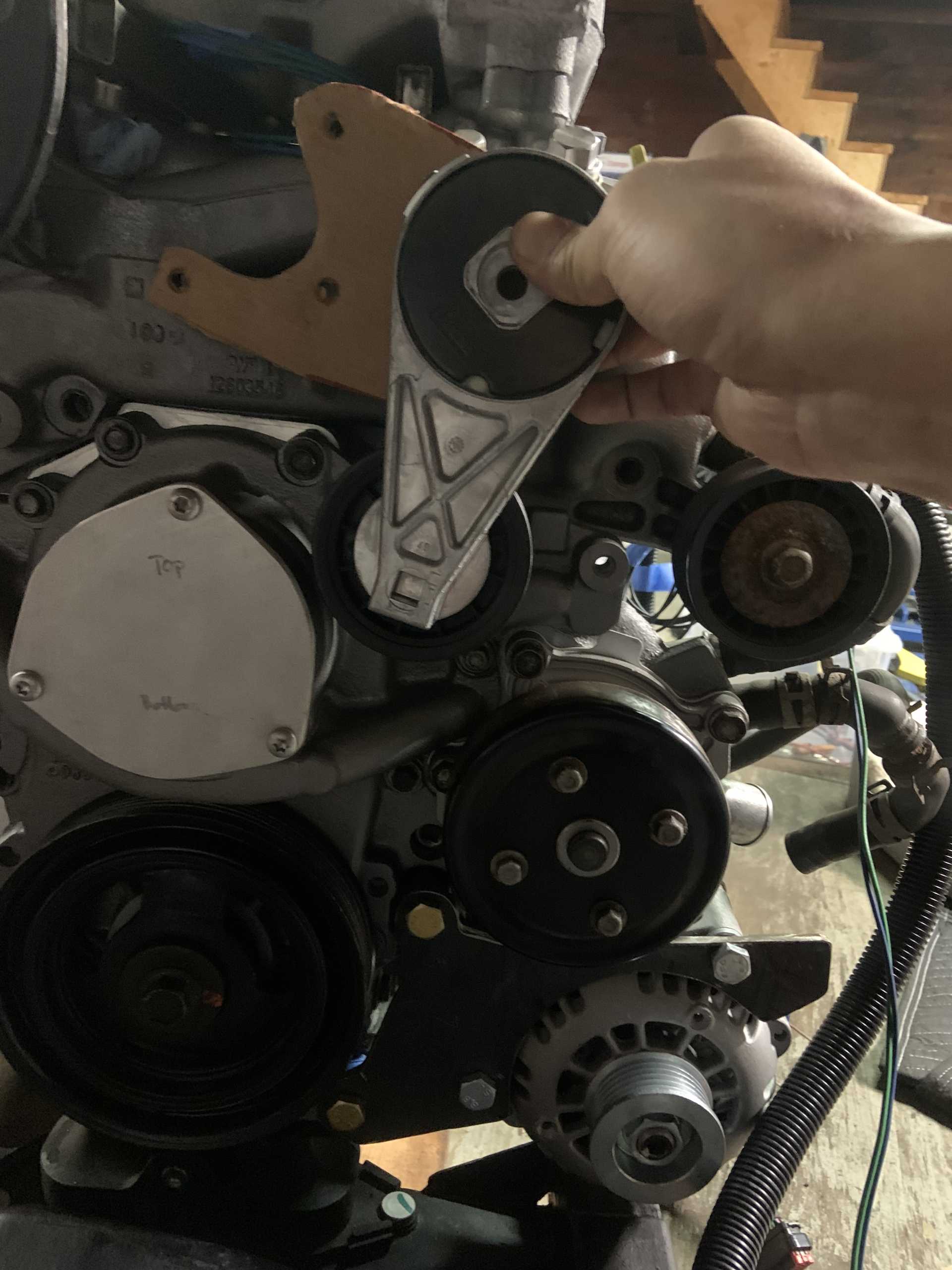
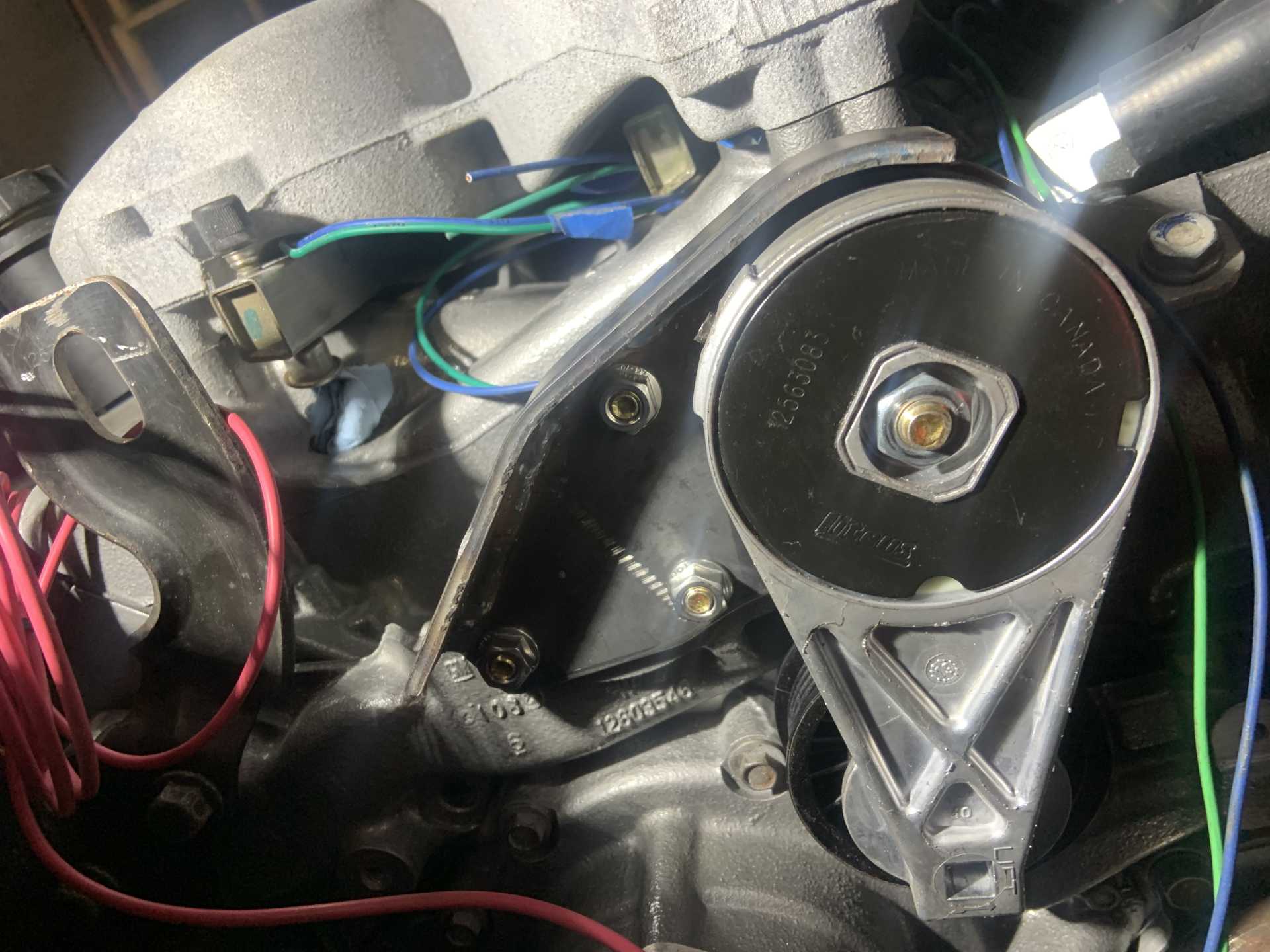
Location of idler pulley to maximize belt wrap on the alternator. The spacing is such that the idler pulley will be above all the bolt heads so I have a good amount of freedom on where I put it.
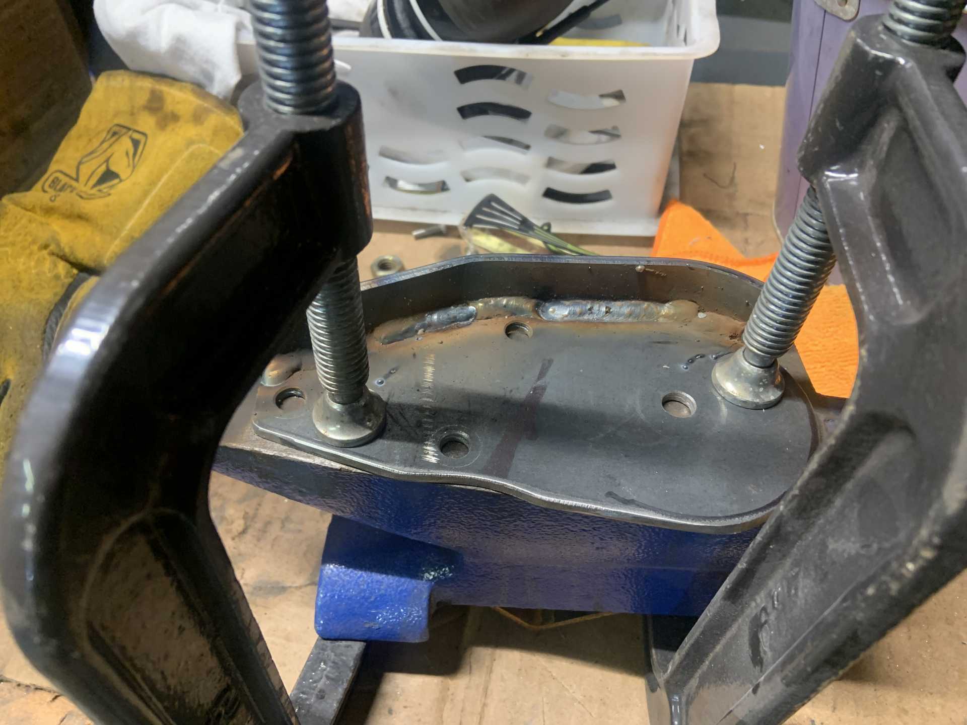
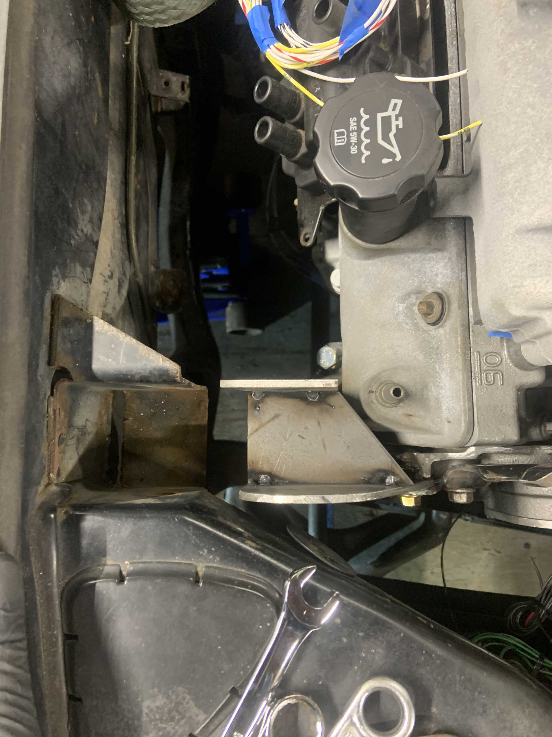
Decided the rear needed to be braced.
Trimmed the main bracket and fully welded the rear support.
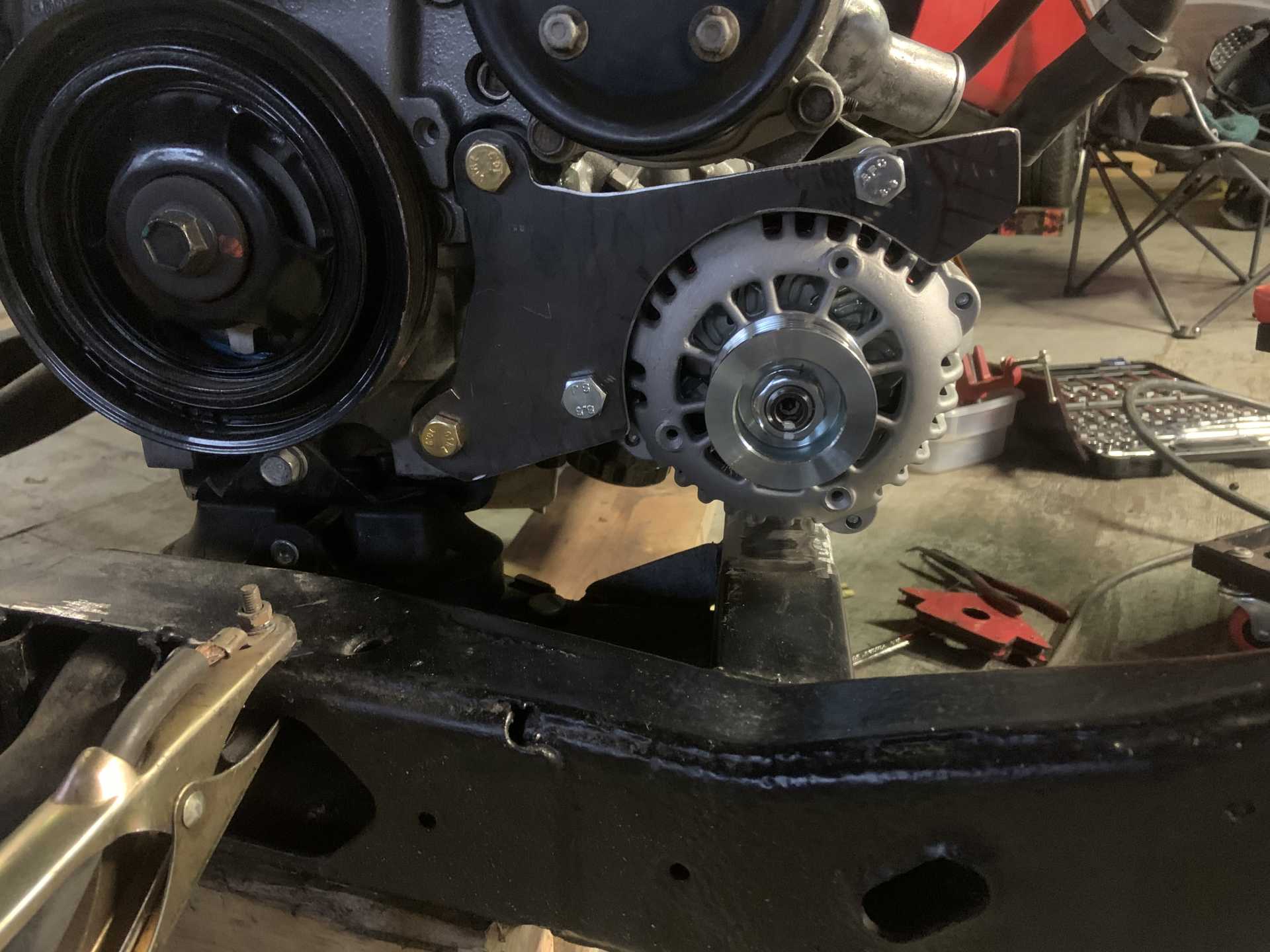
Made a notch in the crossmember for clearance.
And I painted it.
Still have to mount the idler, and make actual spacers with some steel round stock, as well as do some more trimming of the main mount. I had sized the mount originally to be able to bolt on flush, this required me to give it more clearance to the water pump than it actually needs at the spacing that it is at. I may send out to have on laser cut to a more precise shape, or I may just cut another one out by hand. At the same time the current iteration feels plenty strong so I may just leave it.
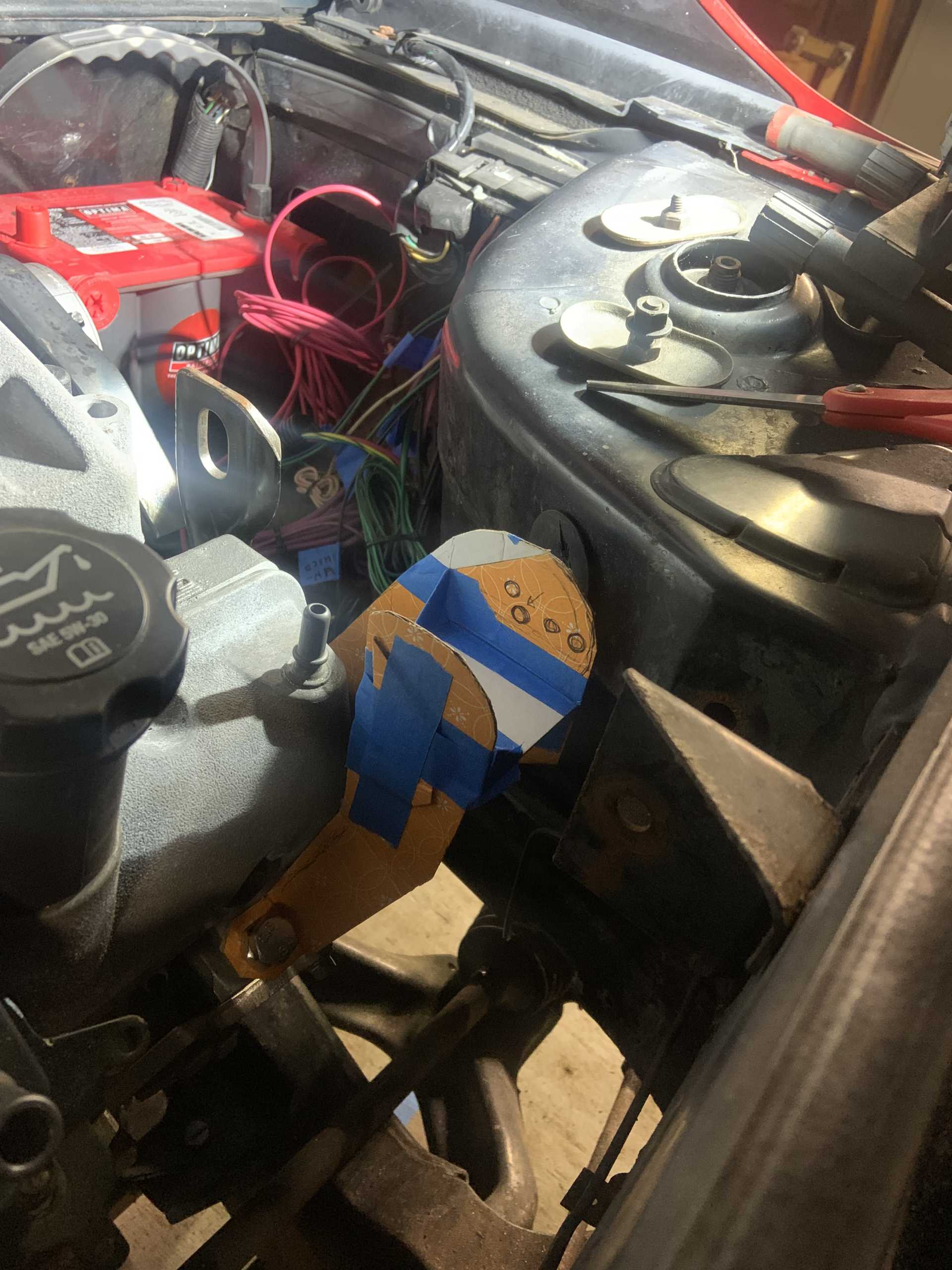
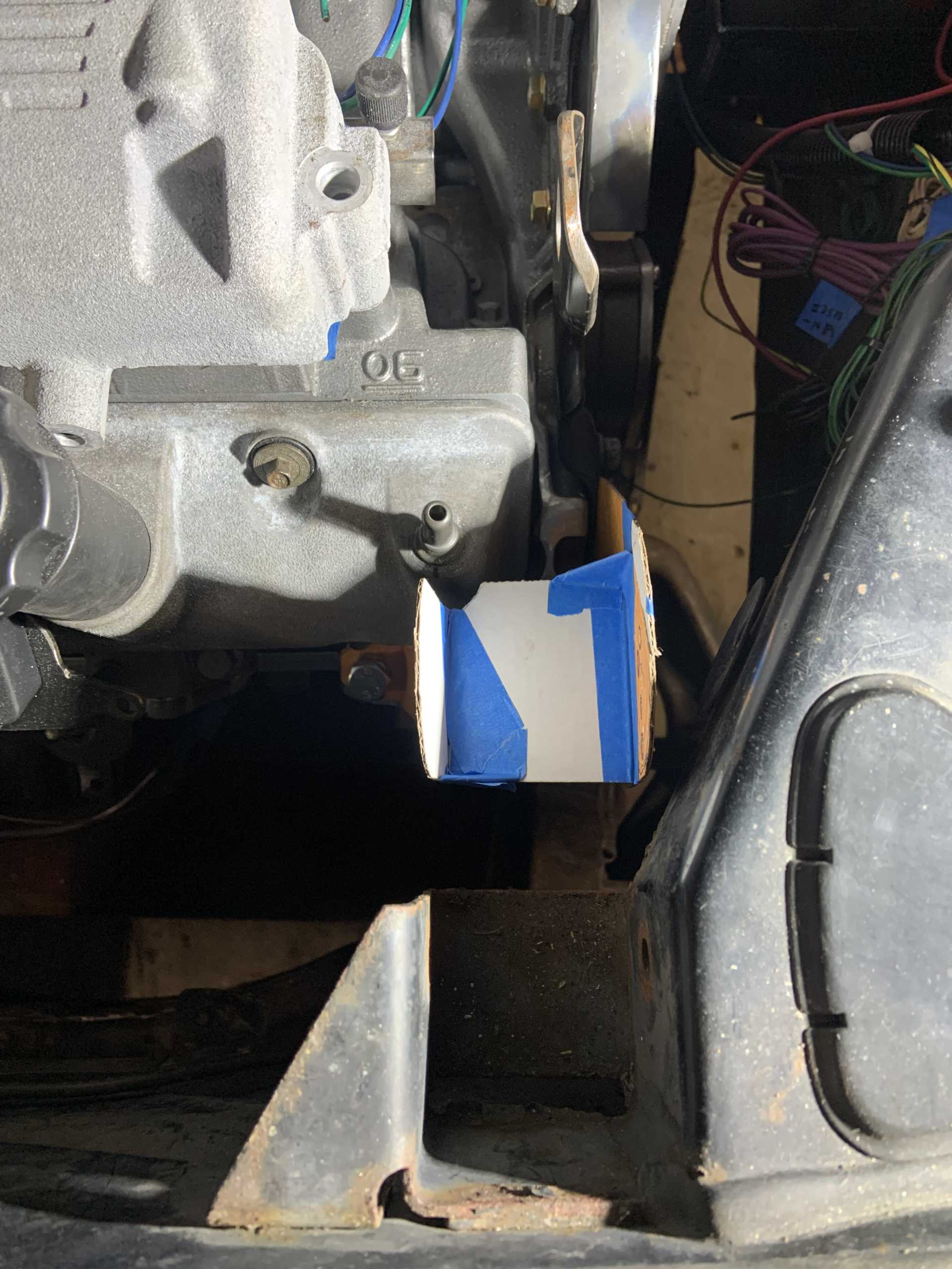
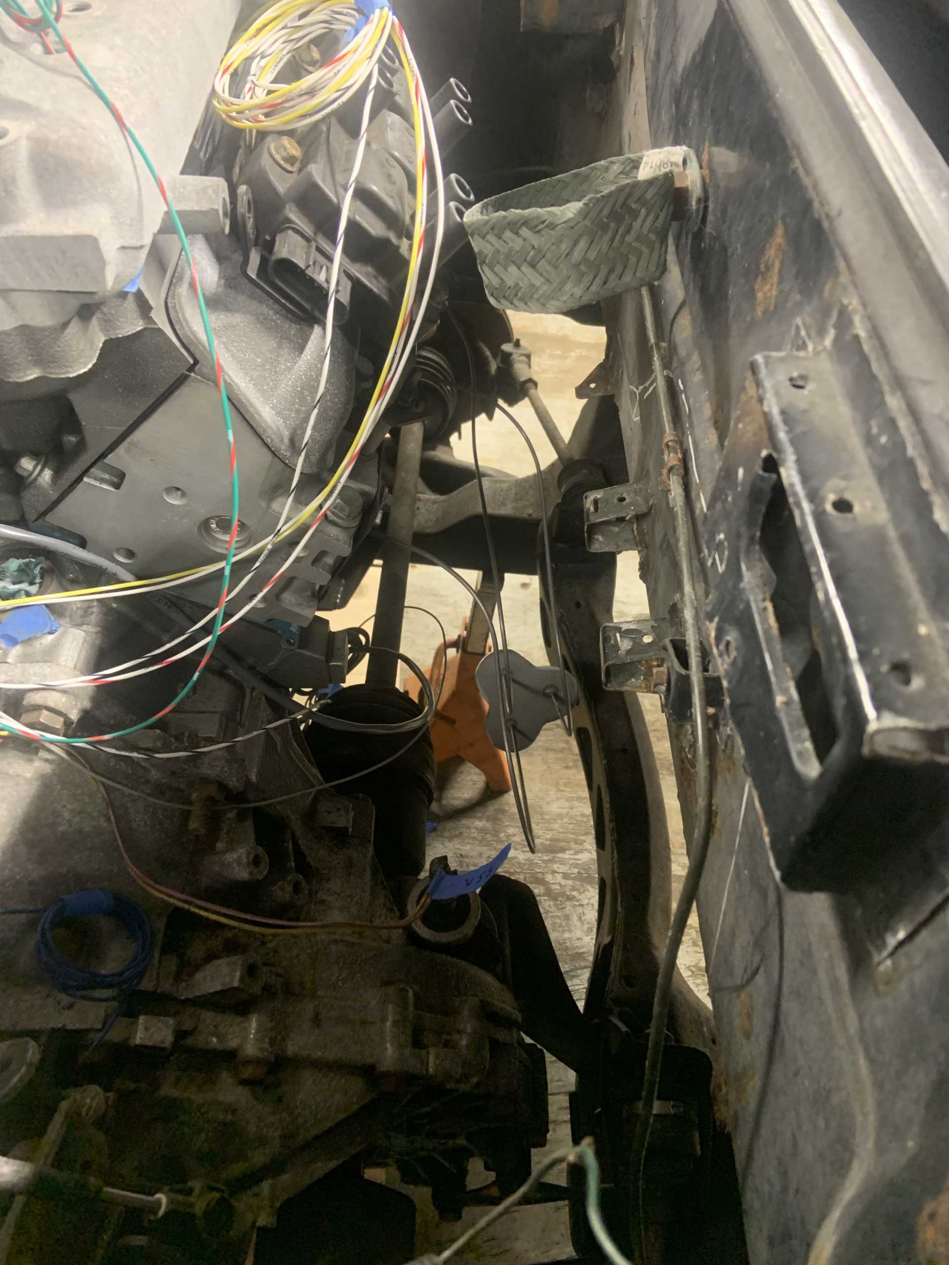
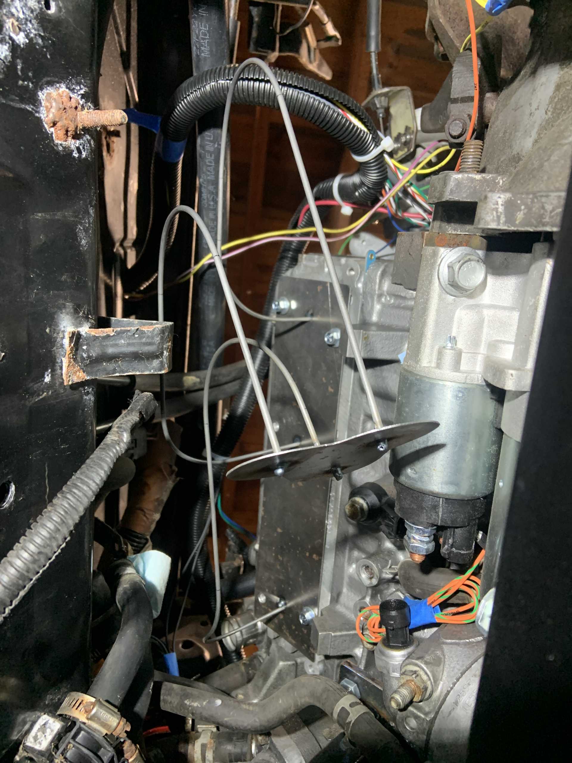
This was the last bit of major fab required, this took a couple full days, and I did not want to reinstall the cradle until this was done. It is still not done but most of the way there. Before reinstalling the cradle I want to get the fuel lines ran and fuel pressure regulator installed, the battery box made and mounted, and run the stock wiring C500 to get it ready to splice into the Microsquirt harness.
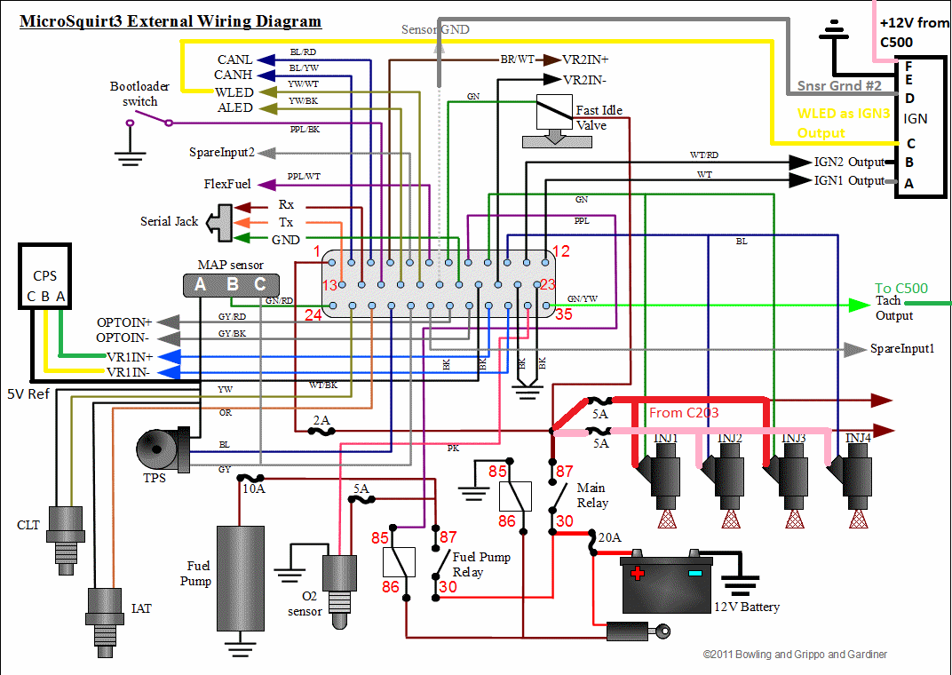
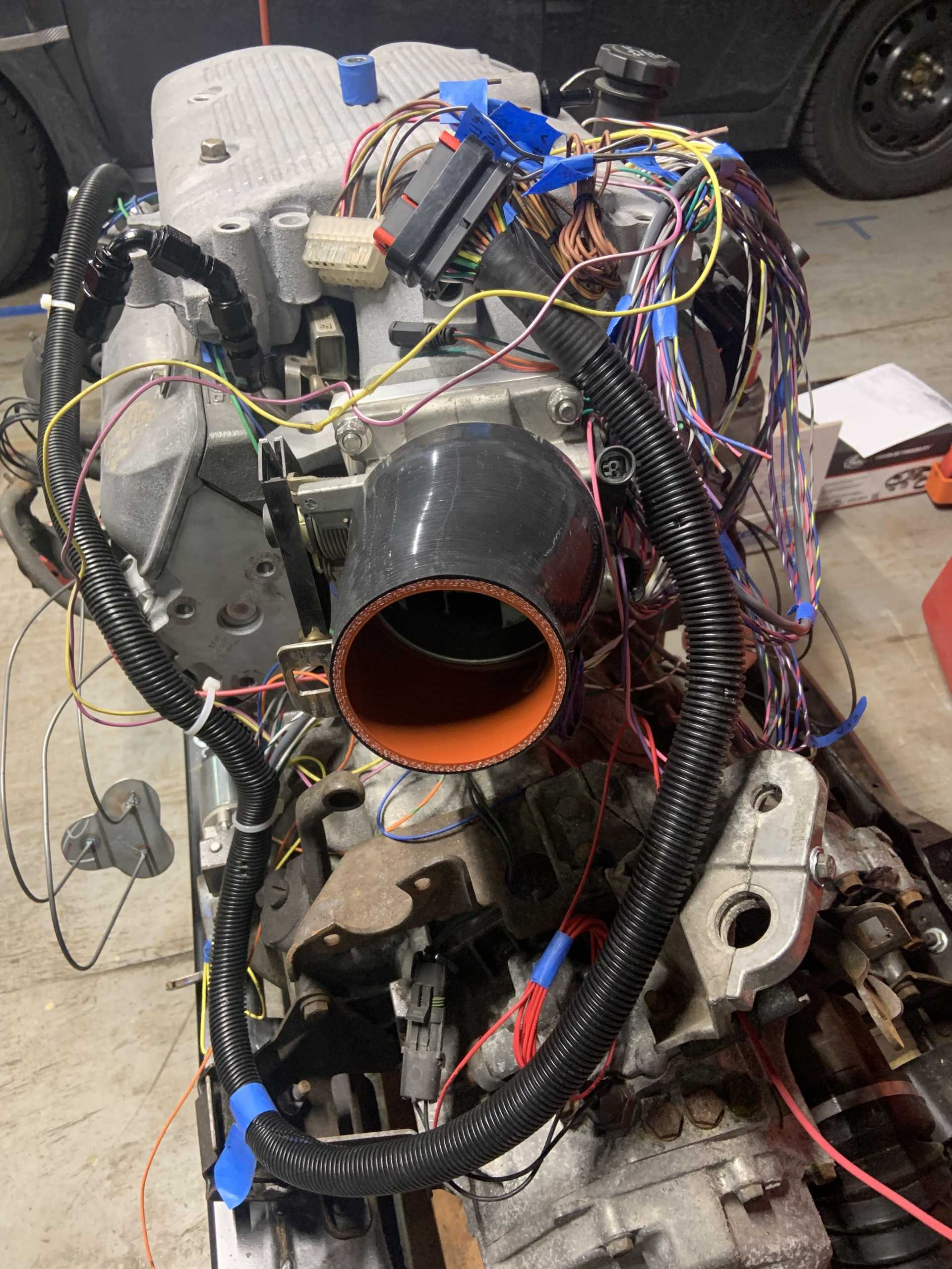
Been working on the wiring, it has been a lot of research and making diagrams to keep everything straight.
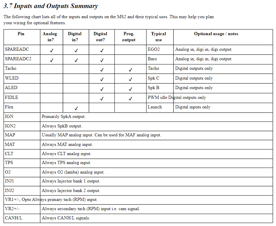
First, some Microsquirt info on how things are wired and can be wired.
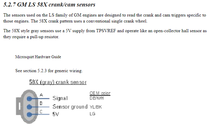
Wiring the Crank Position Sensor (CPS)
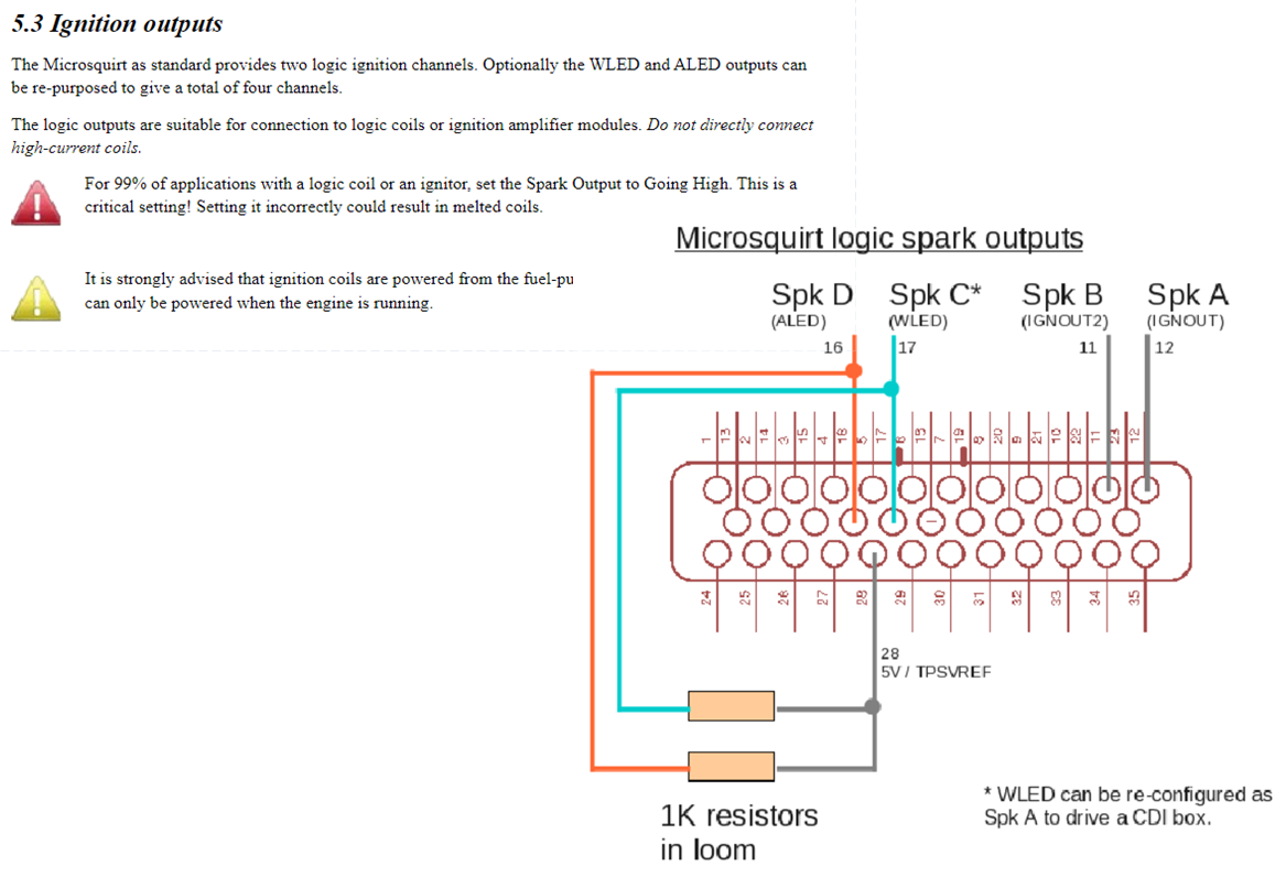
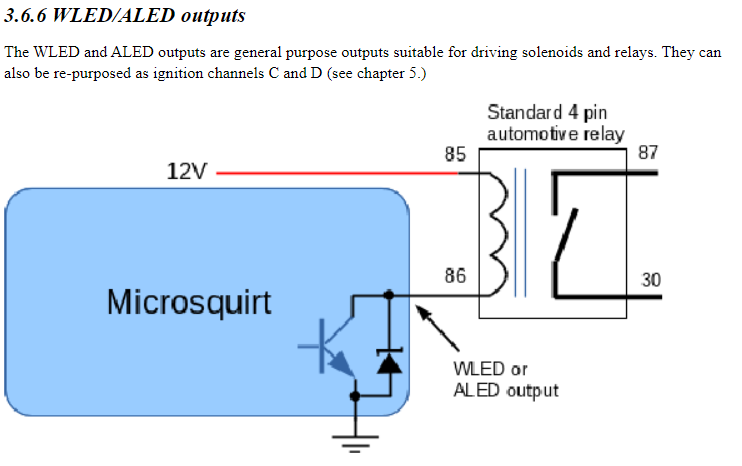
Wiring the ignition. I will be using WLED output with the 1K resistor to 5VREF to power the 3rd ignition channel needed for the DIS.
And I will be using the ALED output to run the fan
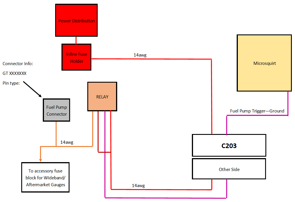
And triggering the fuel pump relay with the Fuel Pump trigger wire from the Microsquirt. The Microsquirt turns the relays on with ground, so I will be wiring them that way.
I am going to run a dedicated hot wire from the power junction through the C203 using a non-populated spot and have that go to a relay located next to the ECU to turn power on to the pump and some accessory gauges. There will be a small fuse block with a few spots to run these things next to the relay.
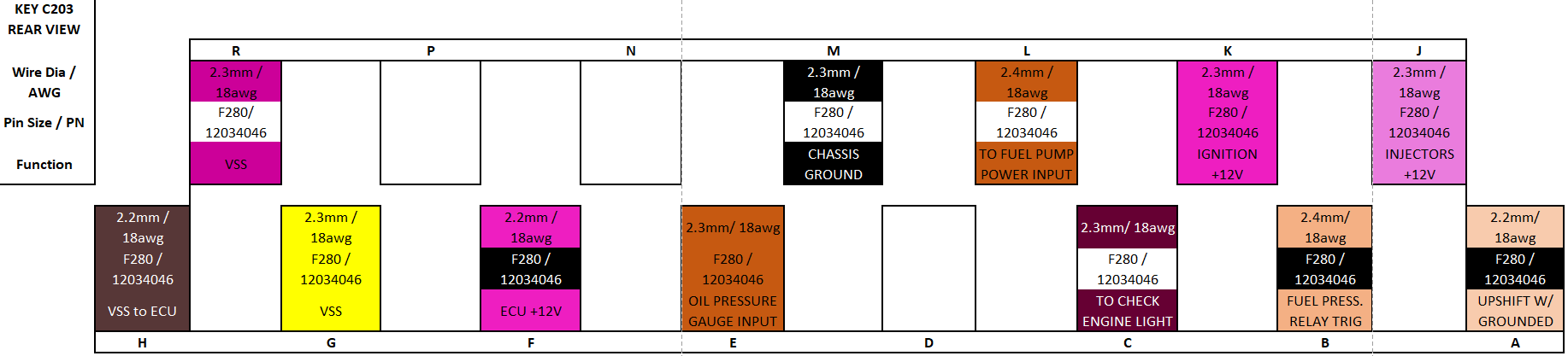
Here is the C203,this diagram has wire gauges and the pins needed to rewire it :
I will be using pins J and K to send power to the fuel injectors, and there are two injector trigger wires coming out of the Microsquirt to ground the injectors for batch firing the two banks. Since the firing order is 1 2 3 4 5 6, it already alternates banks every time it fires, so I will wire the two banks on different triggers.
Pin F will power the Microsquirt, Pin E will receive input from the oil pressure sensor, it is a 0-90ohm sensor so it should still work with the gauge. I will also have the line spliced to go to an input on the Microsquirt so that I can log oil pressure.
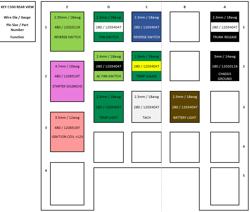
Here is the C500, this diagram has wire gauges and the pins needed to rewire it:
Pin E3 will provide power to the ignition coil, D1 will be tied to the ALED output from the Micosquirt to trigger the fan, C2 will go to an output from the temp sensor, I will use this coolant temp sensor which is 3 pin to be able to send coolant temp signal to the Microsquirt as well as the temp gauge. PN: 10096181
C3 will be tied to the Tach output wire from the Microsquirt to run the tach, and B3 is the battery light wire that will go to the alternator.
Here is an overall wiring diagram of how it will look.
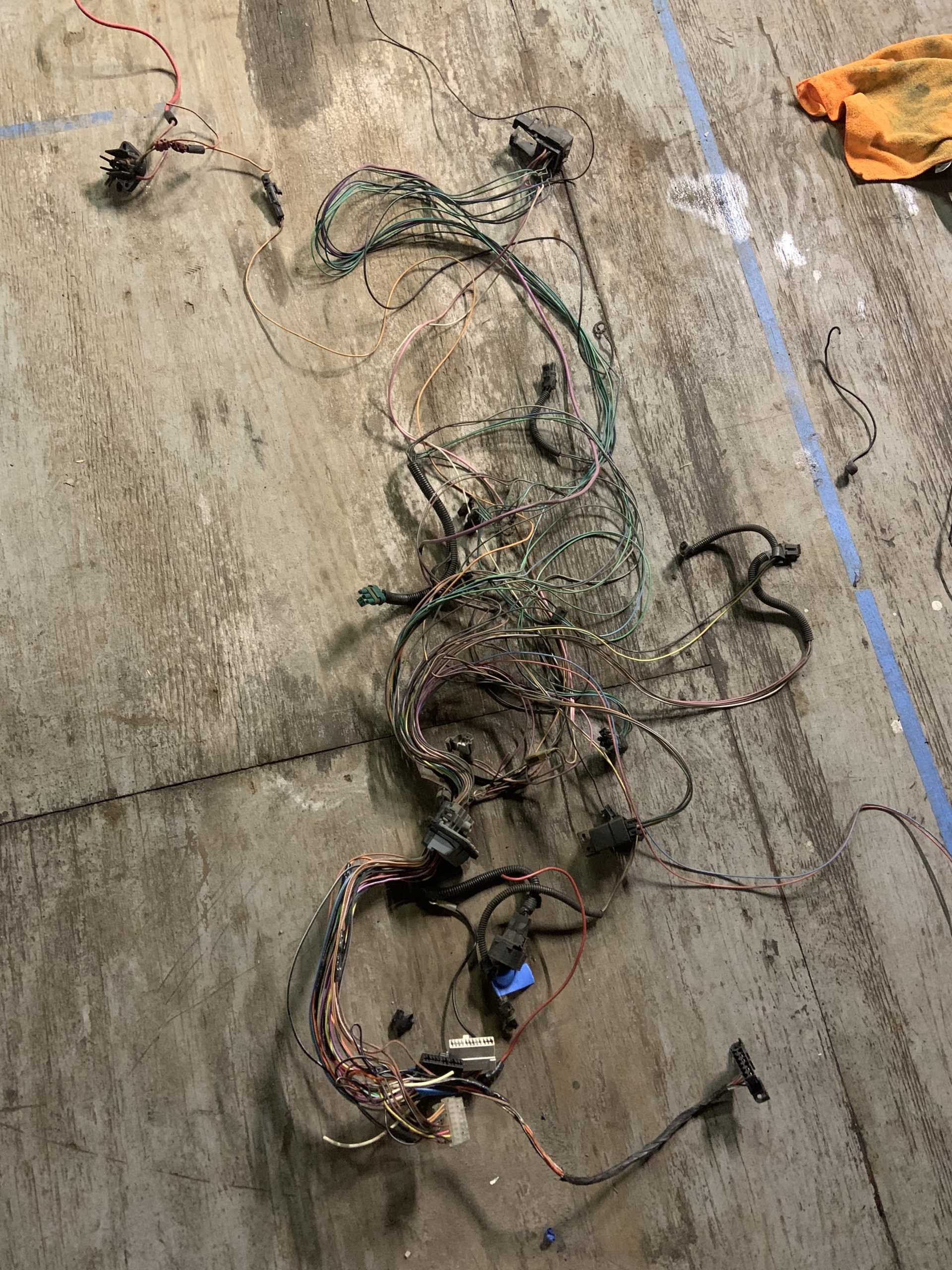
I removed all the insulation from my original 4cyl wiring harness. I was able to figure out why back in 2010 I started getting an intermittent power issue to ECU, I solved it at the time by running new power wires to the ECU.
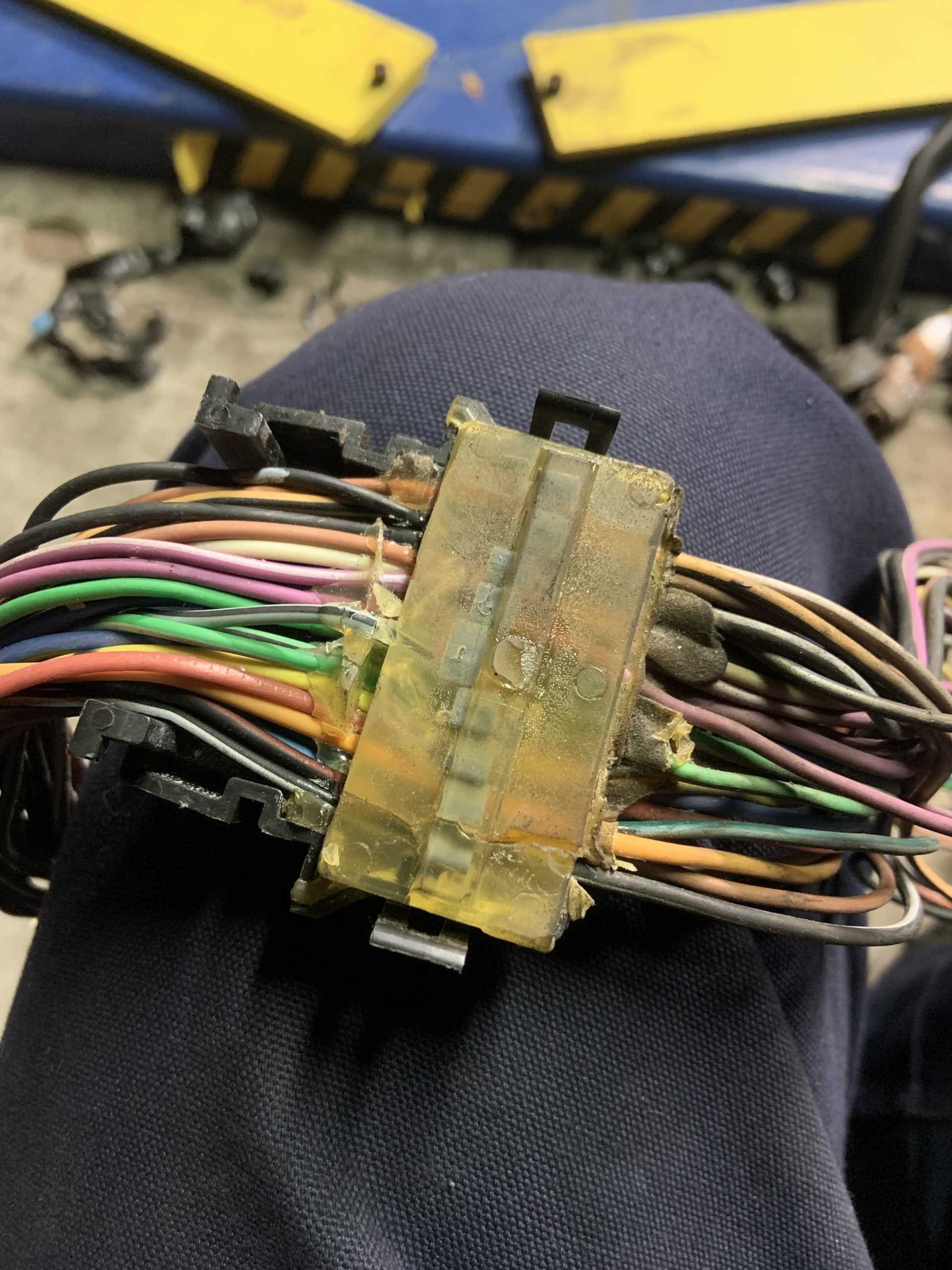
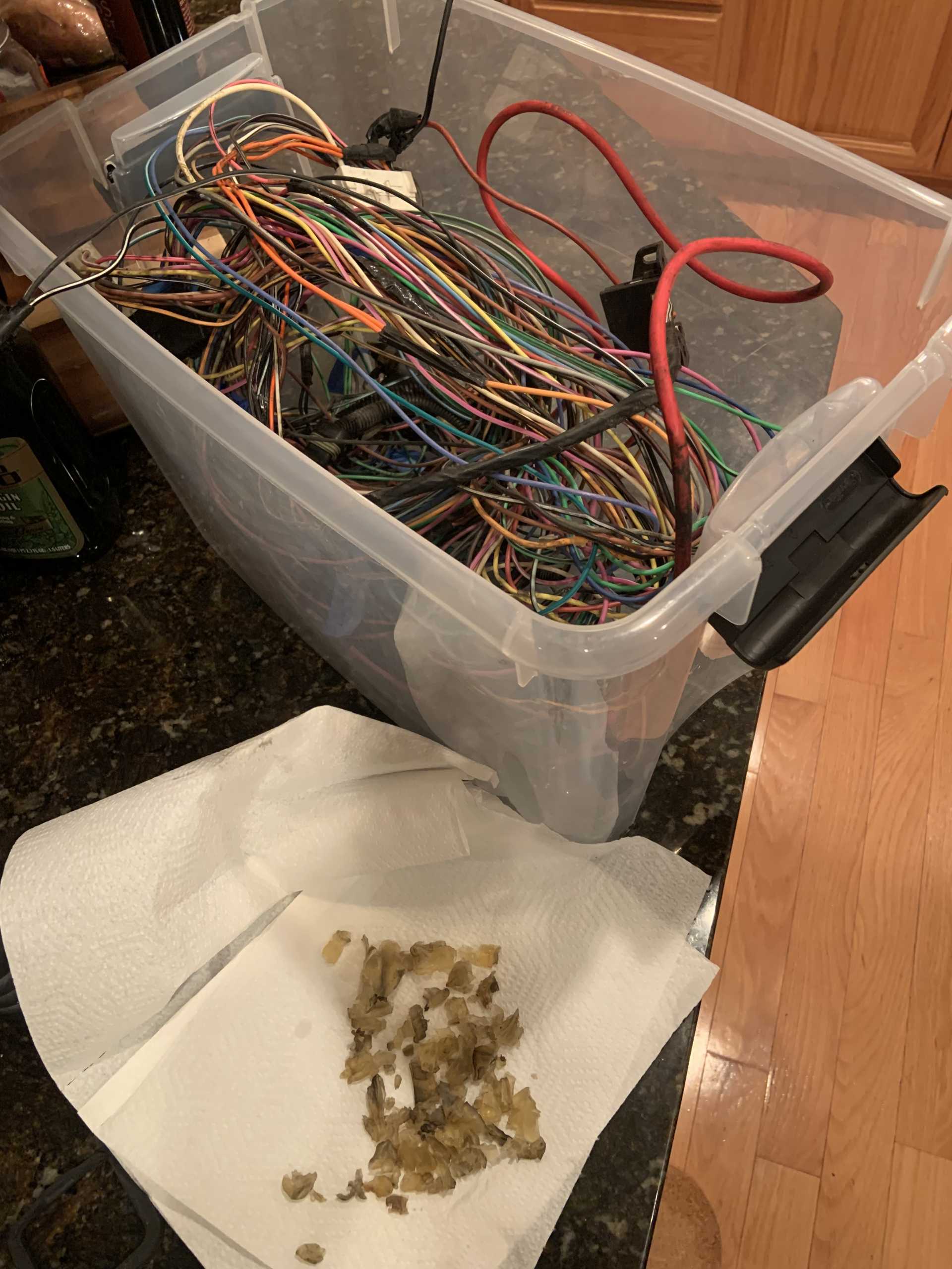
I boiled the bulkhead pass through using Fieroguru's instructions, worked great.
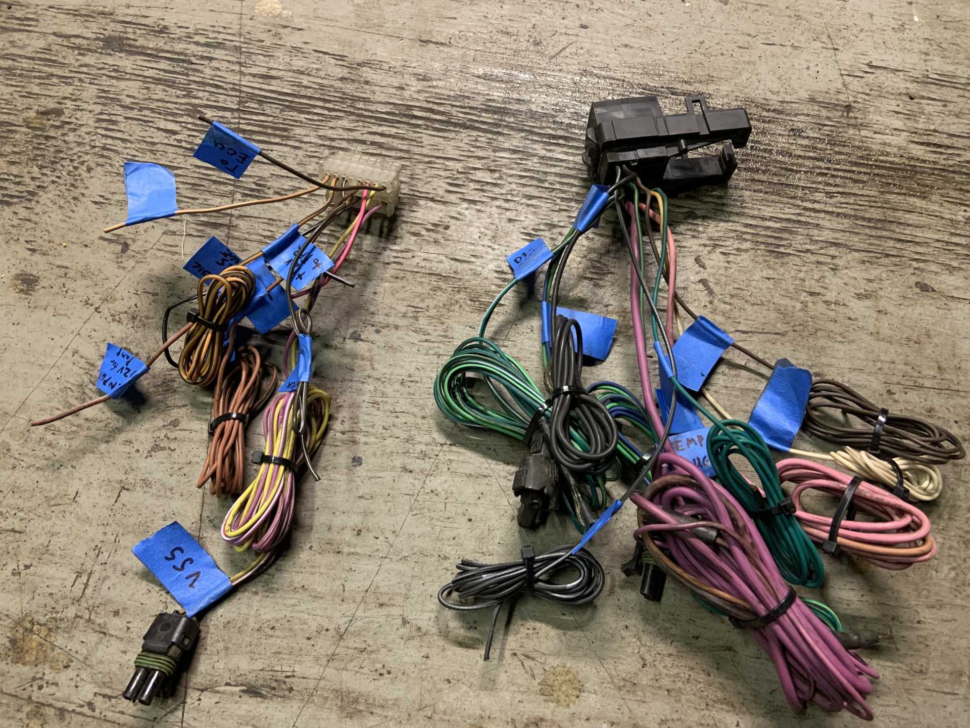
After figuring out what I was doing and making all my diagrams, I paired the harness down to the connectors I need, and trimmed any wires I will be replacing and labelled them to make it easier to see where everything was.
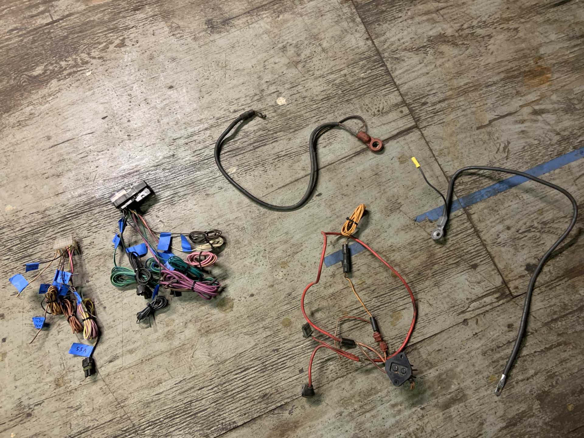
Here's the wiring I am using:
And the wiring I am not (though I will reuse the fuel pump relay)
I ordered new pins for C500 and C203, here is a list of all the possibilities:
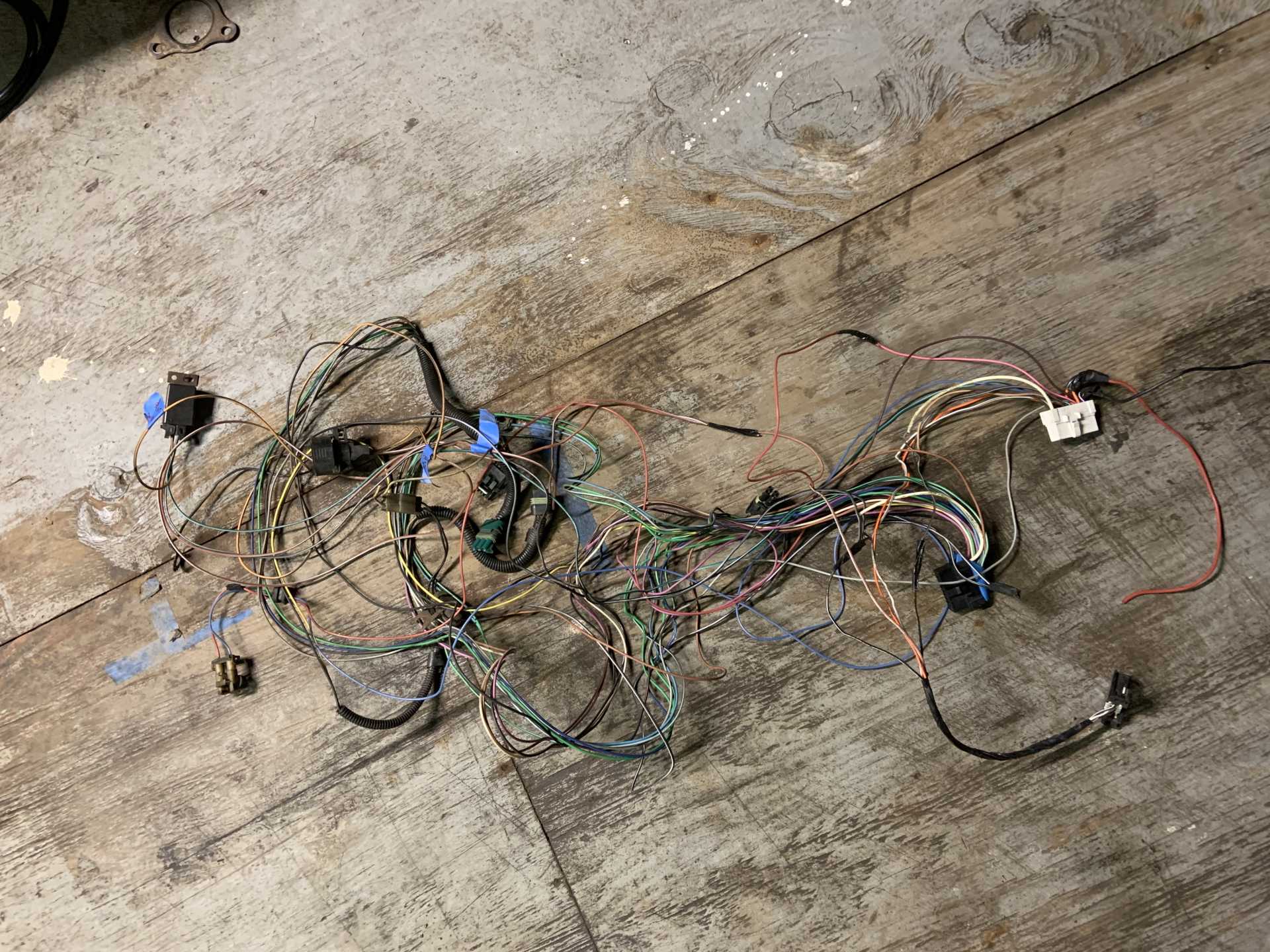
I then started laying out the harness on the motor and routing all the wires where they need to go.
Still working on this but going to start cutting and splicing wires and crimping things soon, I already have all brand new connectors for everything. I need to get a new connector for the 3 wire coolant temp sensor that I need to buy.
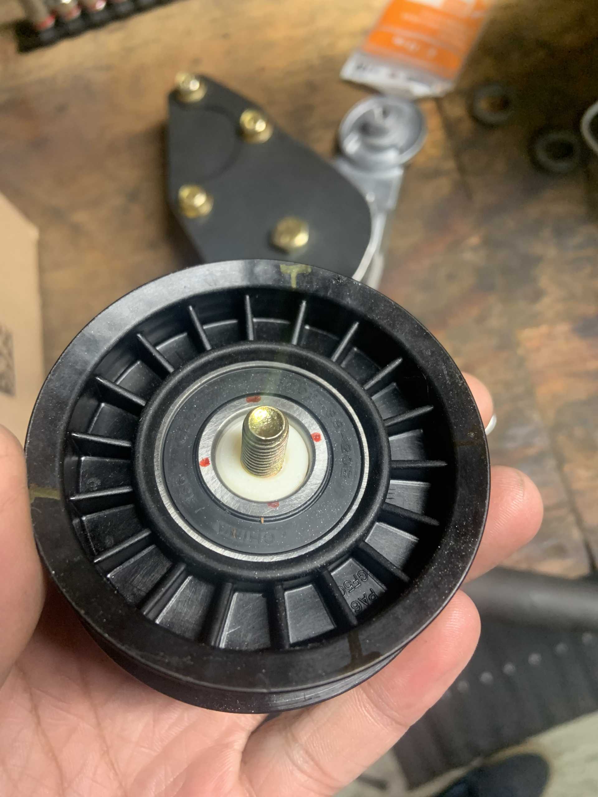
And I figured out a better belt routing solution that seems low effort, I needed a tensioner that tensioned clockwise instead of counterclockwise like the LZ9s, but the 3400 tension fit the bill perfectly so one of those is arriving soon.
I may need to make a bracket for it that bolts to the original power steering pump mounting locations, but there is a chance it all lines up and I can drill into the PS mounting bracket and bolt it up, maybe with a small spacer.
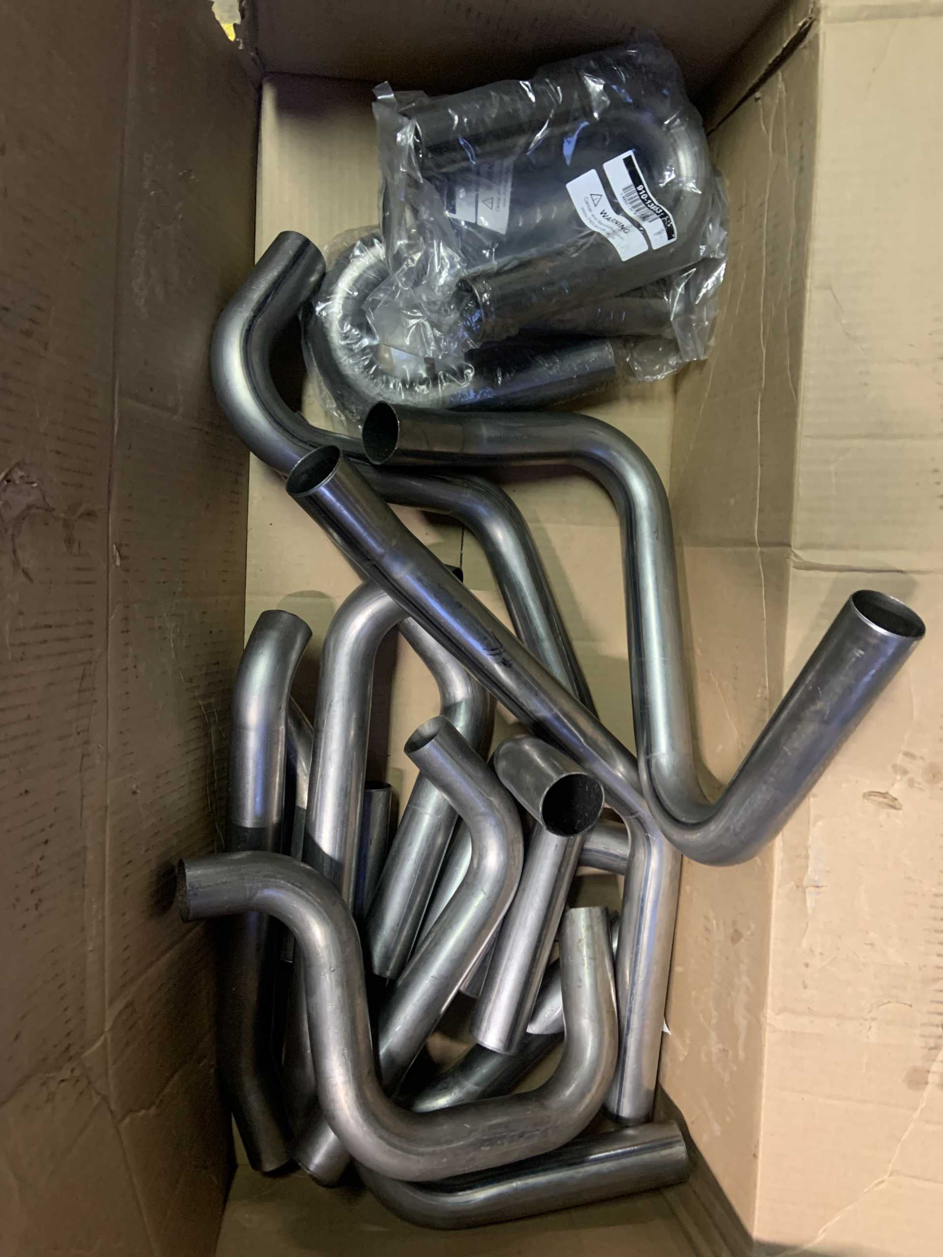
And finally, I ordered everything I need to make my headers, I got some V6 collectors from the UK, a selection of mild steel 1.75" tubing and bends, and some V bands to attach the headers to the rest of the exhaust. I plan to get the headers Jet-Hot ceramic coated, they quoted me $400 including shipping, and recommended mild steel for the header material. My header routing plan is no longer to cross over the transmission, and instead have the firewall side header exhaust travel under the motor between the oil pan and motor mount, I need to notch the crossmember I made and probably add a little support for it. It is a little tight with the alternator and oil filter being where they are, but I mocked it up and it should work fine. It will be a 2.5" tube that runs through there.
[This message has been edited by zkhennings (edited 02-13-2023).]
Exhaust tubing came in, did not take much persuasion to get the tubing to fit Eric's flanges.
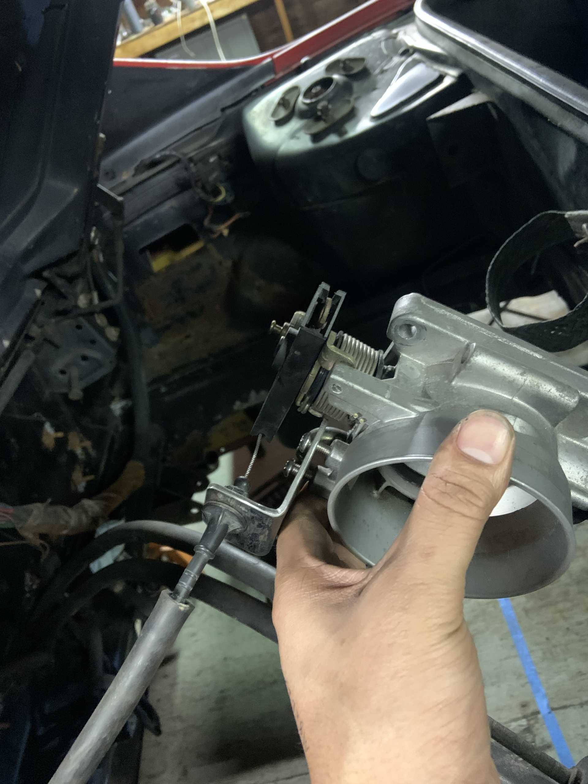
Made a throttle cable bracket to use the 2.8 throttle cable with the Northstar TB.
I played with flipping the TB upside down to get a less extreme bend on the throttle cable, but due to the offset of the flange relative to the throttle opening, it may mess with my Isuzu shift cables. Something to test fit.
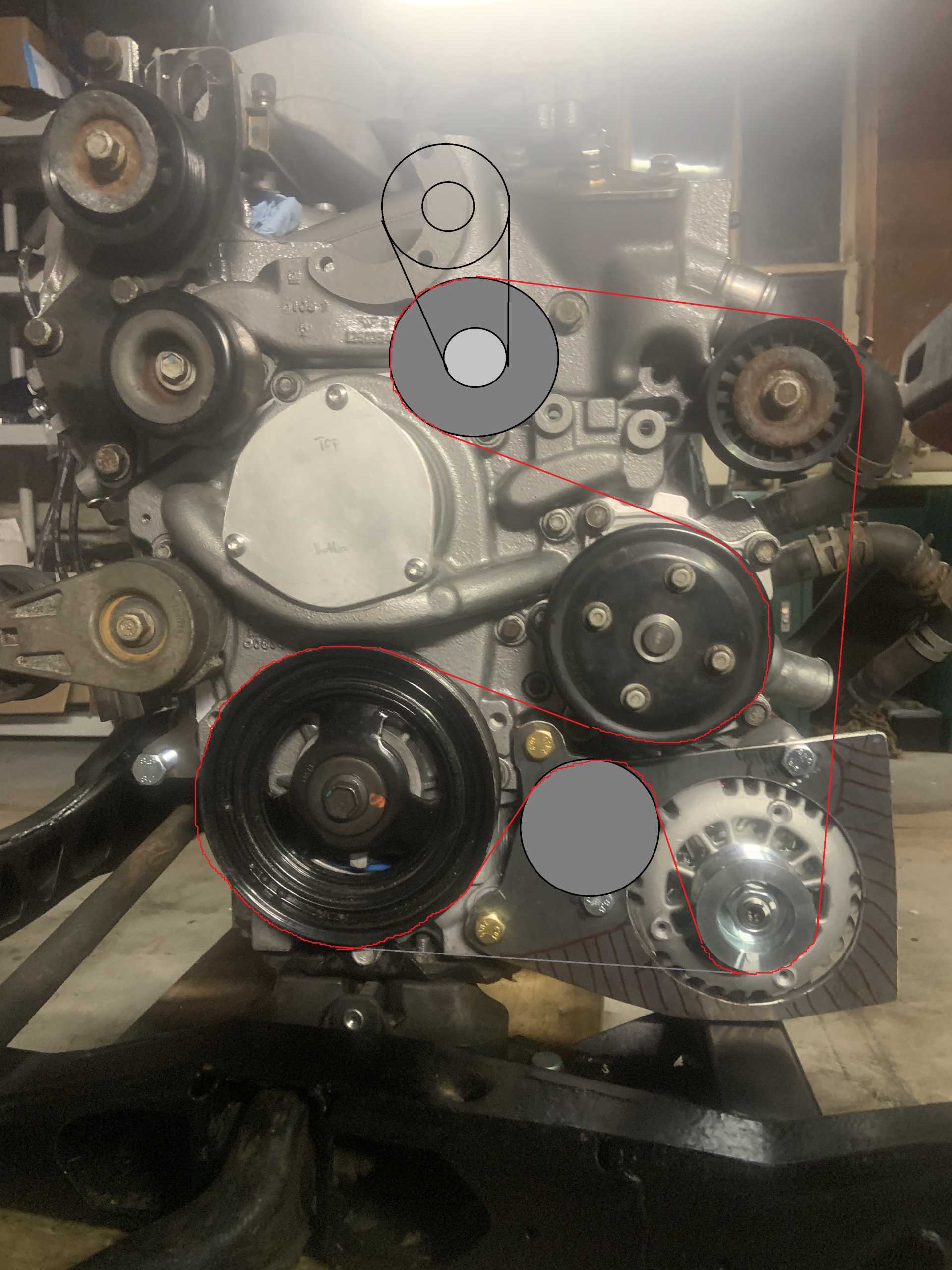
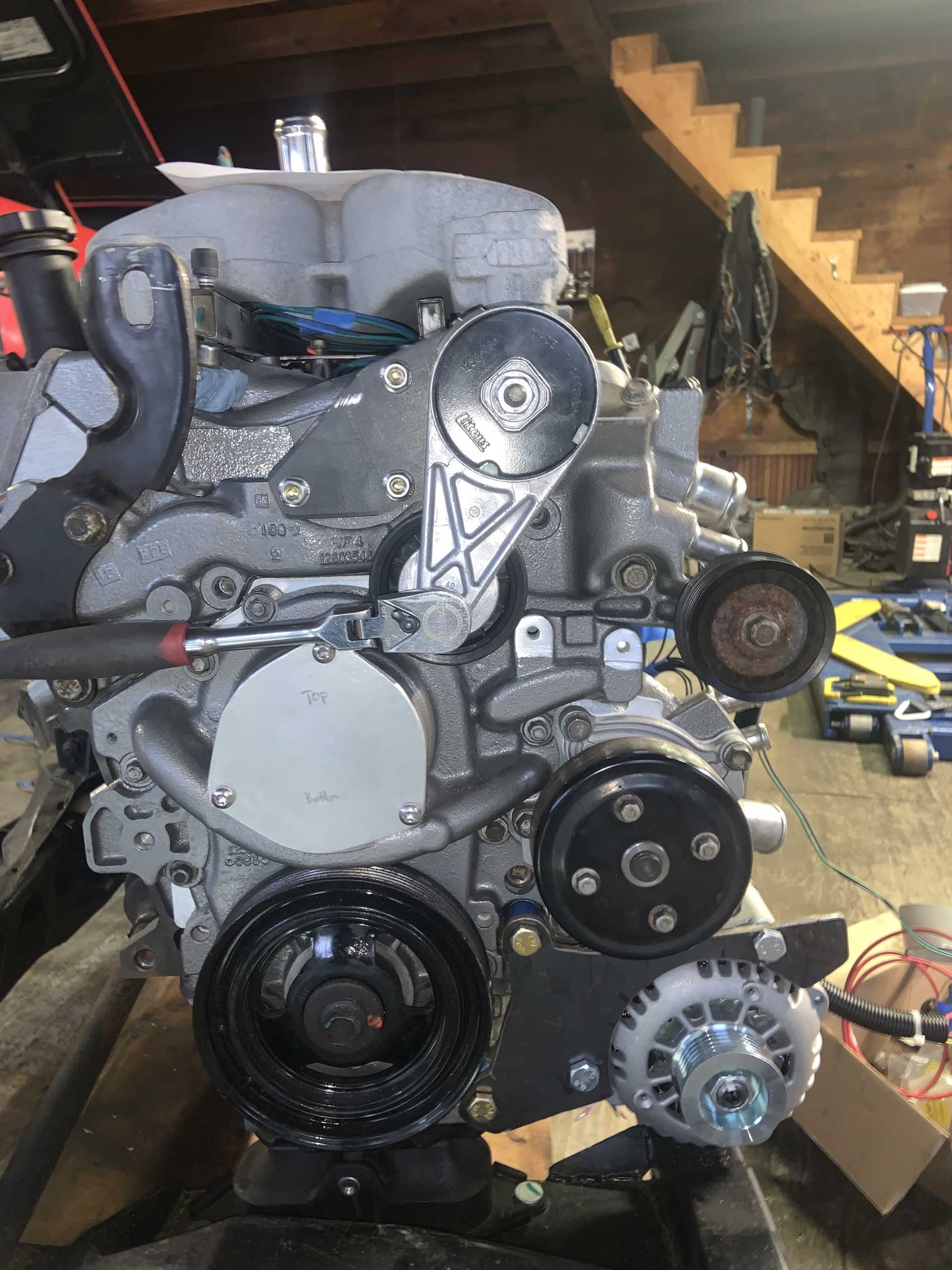
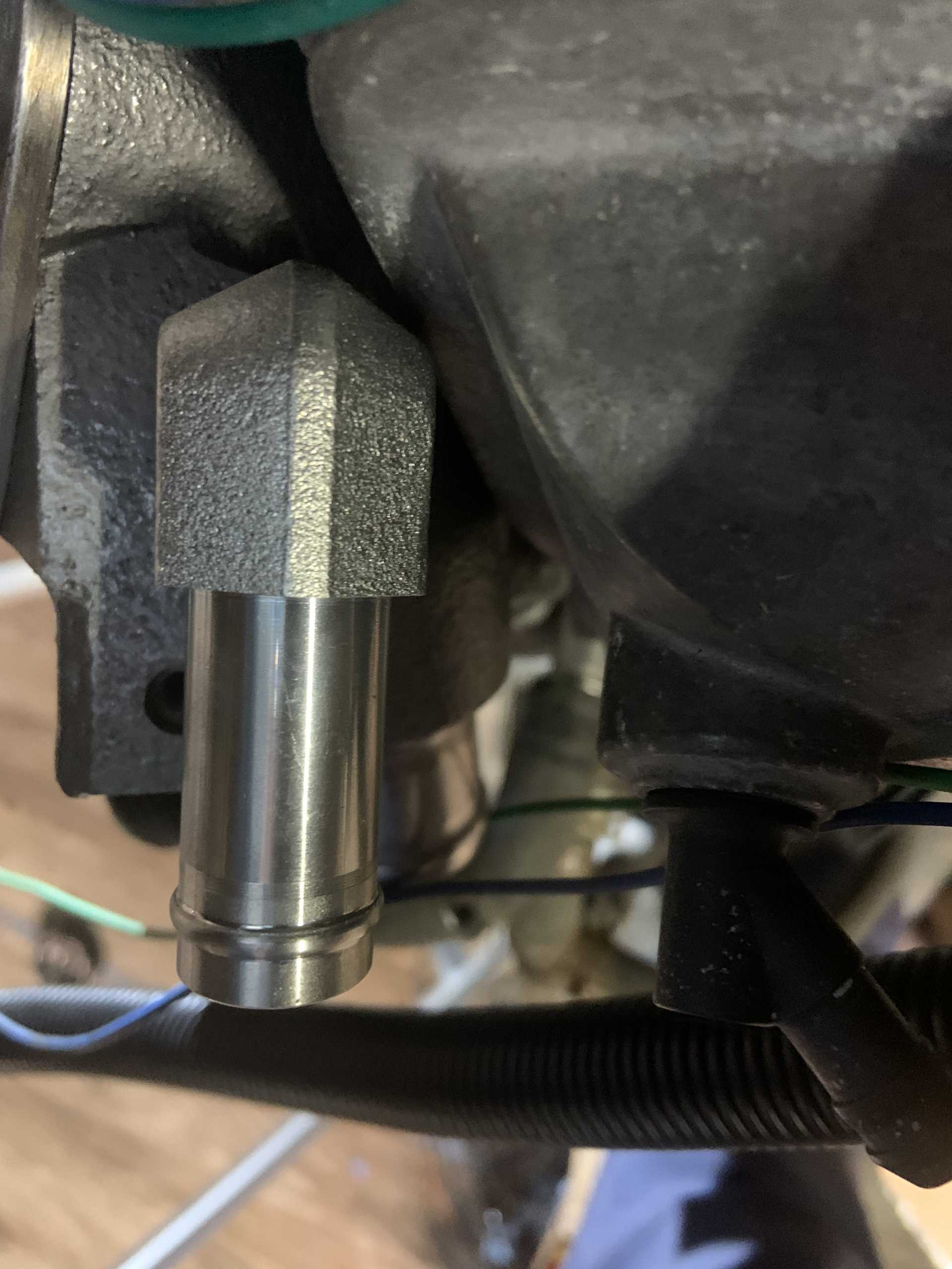
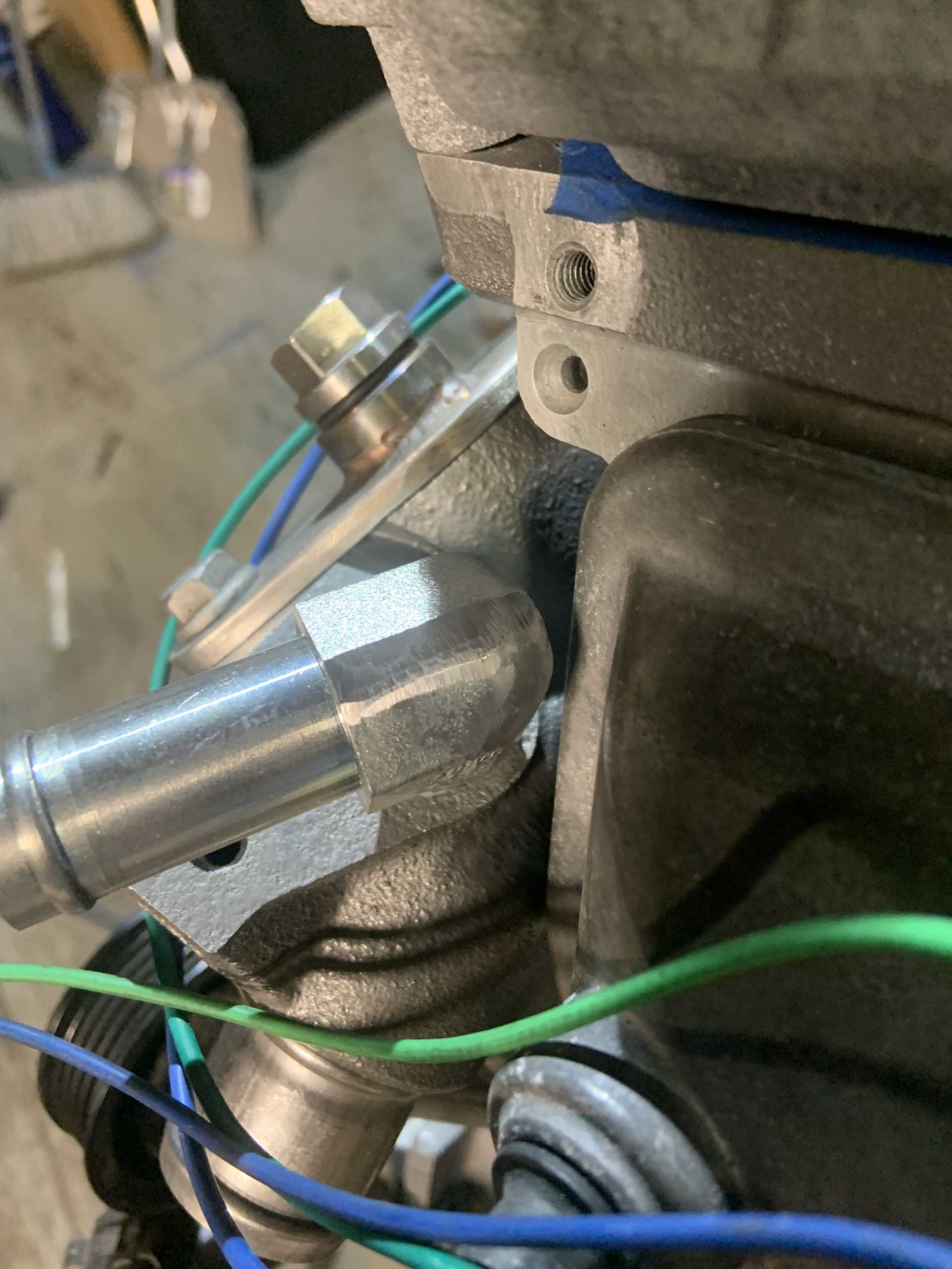
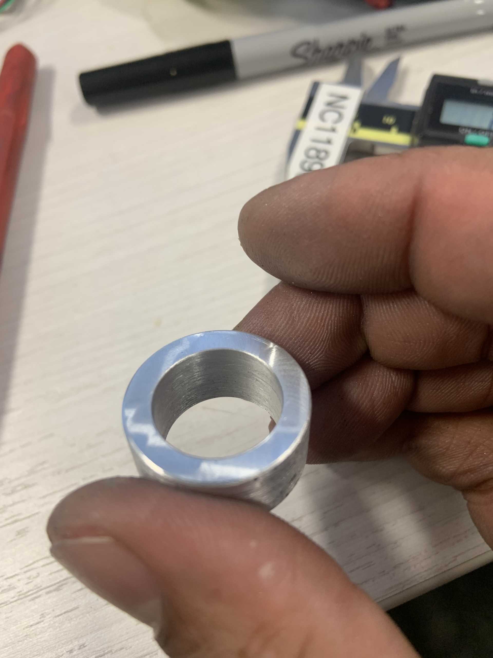
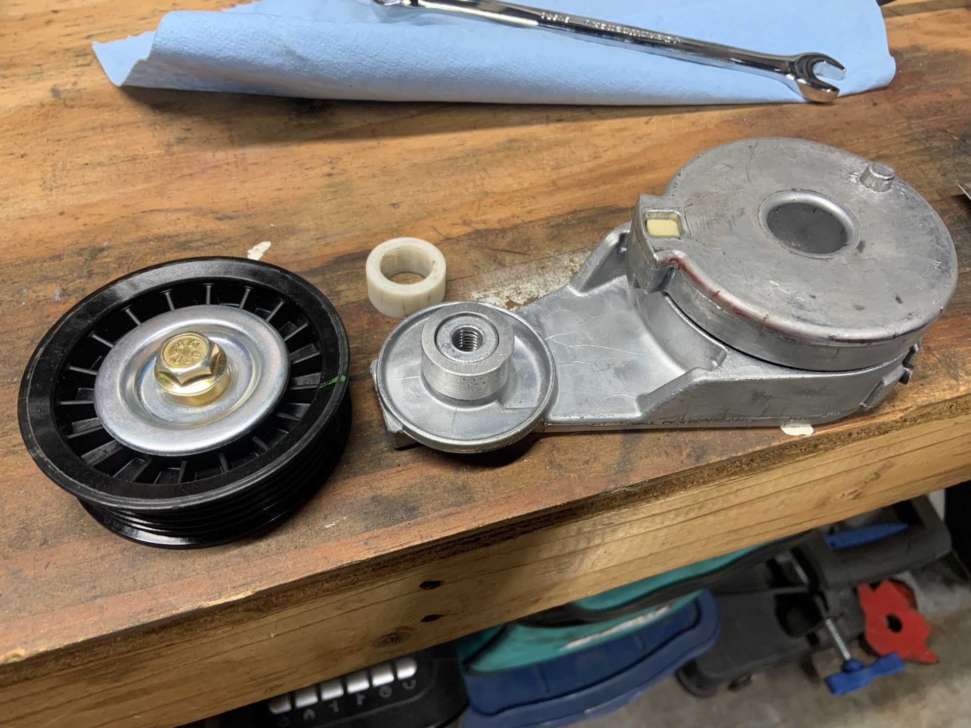
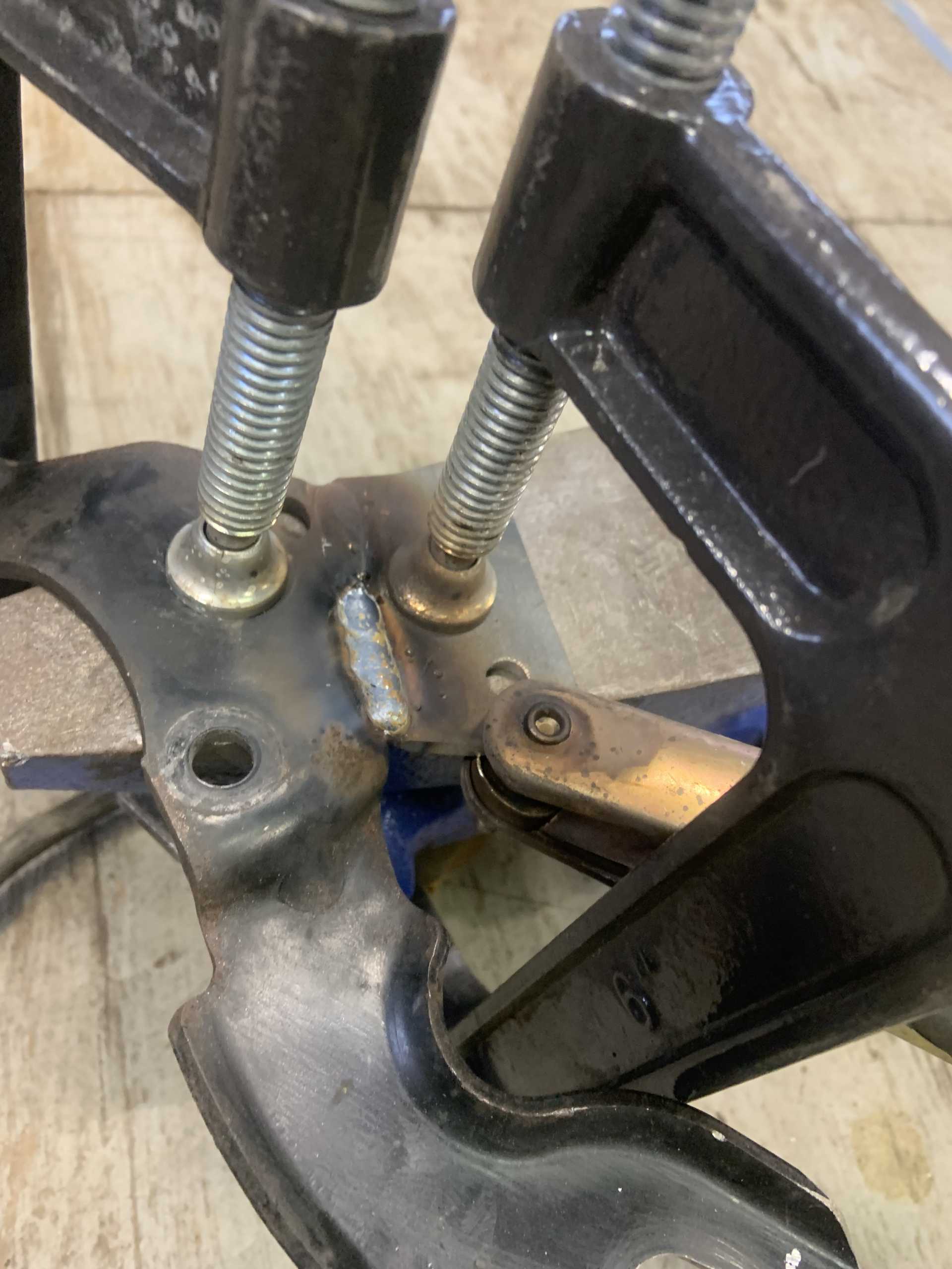
I also worked on the tensioner. I did some CAD and messed with placement and ended up around here.
In order to get the pulleys to line up, I need to offset the pulley that is attached to the tensioner.
I then chopped the offending bosses down on the timing cover. I filed the right boss back to flat since I could use that spot to mount something. The left boss is covered by the pulley so I just smoothed it.
I chopped up the crossover to remove the alternator mounting features I was planning to use for the dogbone. Seems to be a bad idea so I will make one with steel. I regret that I cut off the boss for one of the idler pulleys, now I am forced to get my tensioner positioning to work and it is not as straight forwards as it first appears.
Did some more CAD and placement as I found the pulley interferes with the water passage below the left boss. I had to raise the pulley pivot and then position it to clear all the coolant fill business.
Tensioner positioning after new discoveries.
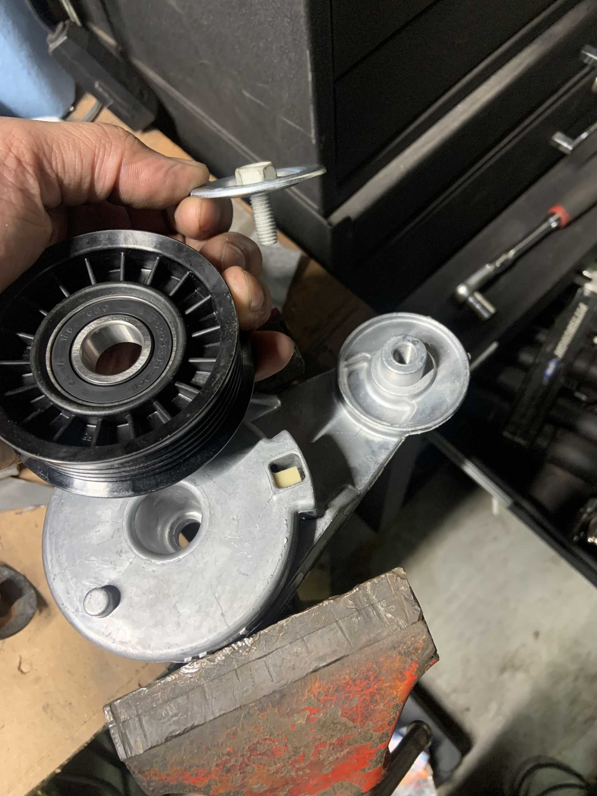
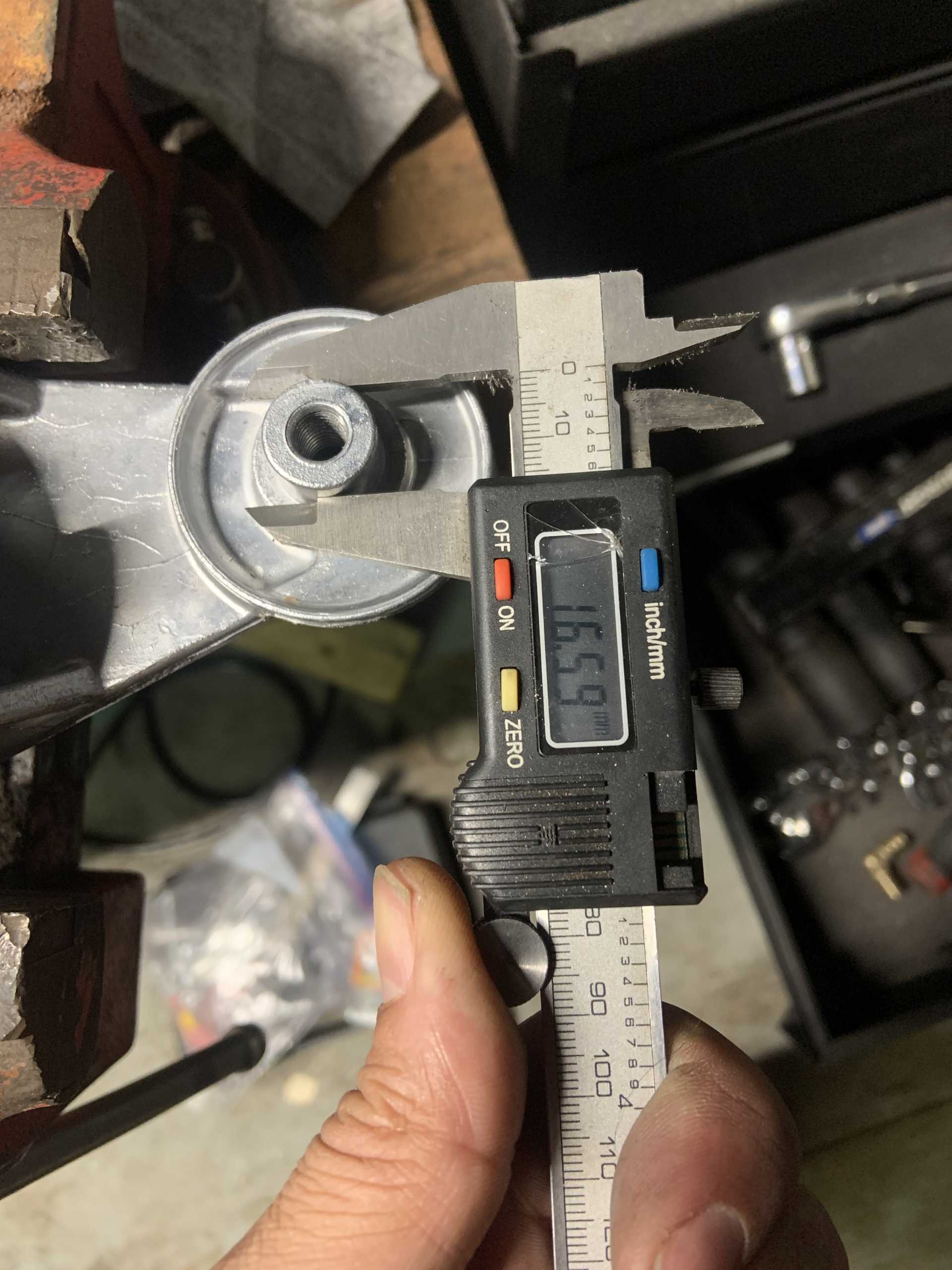
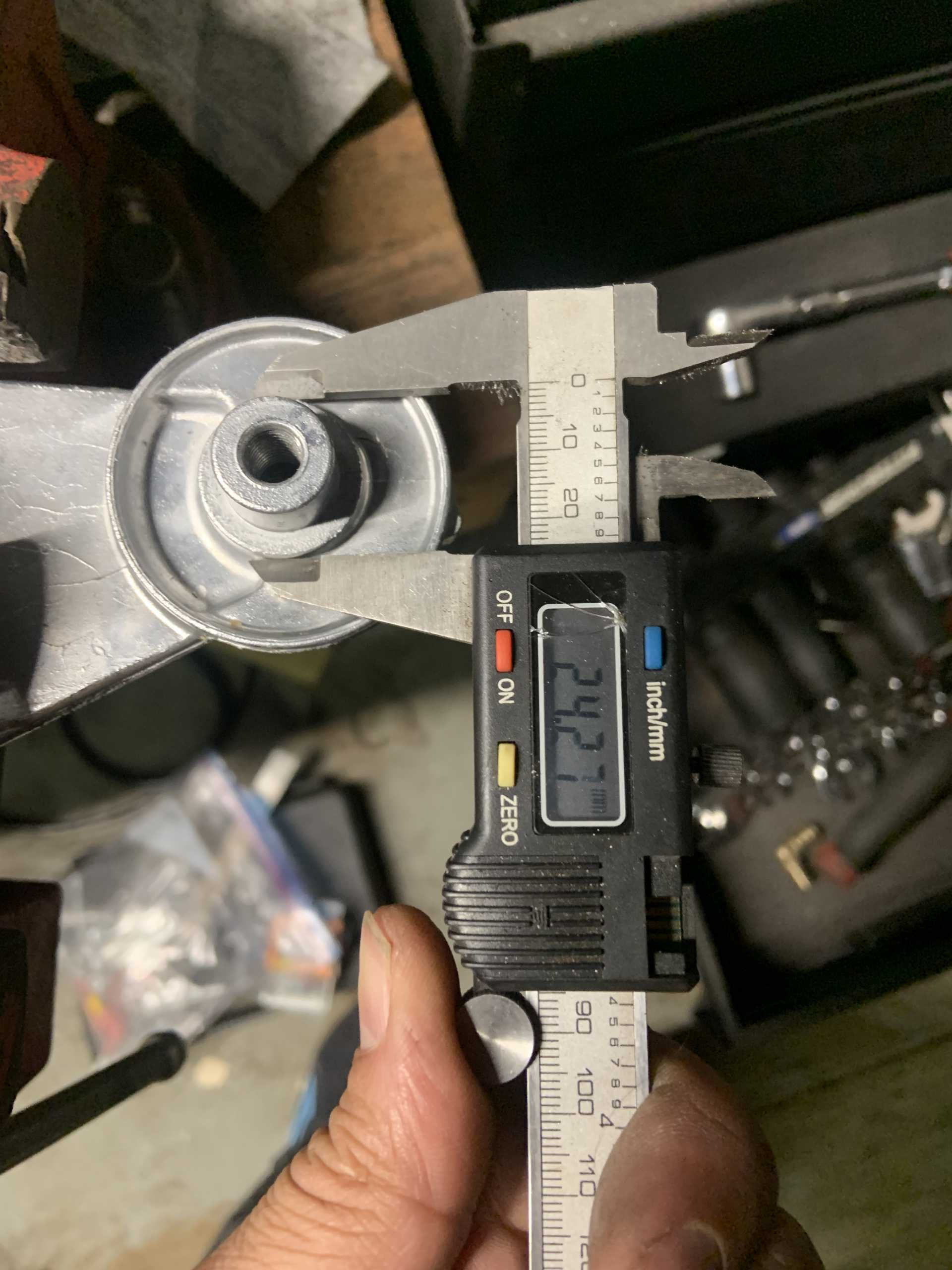
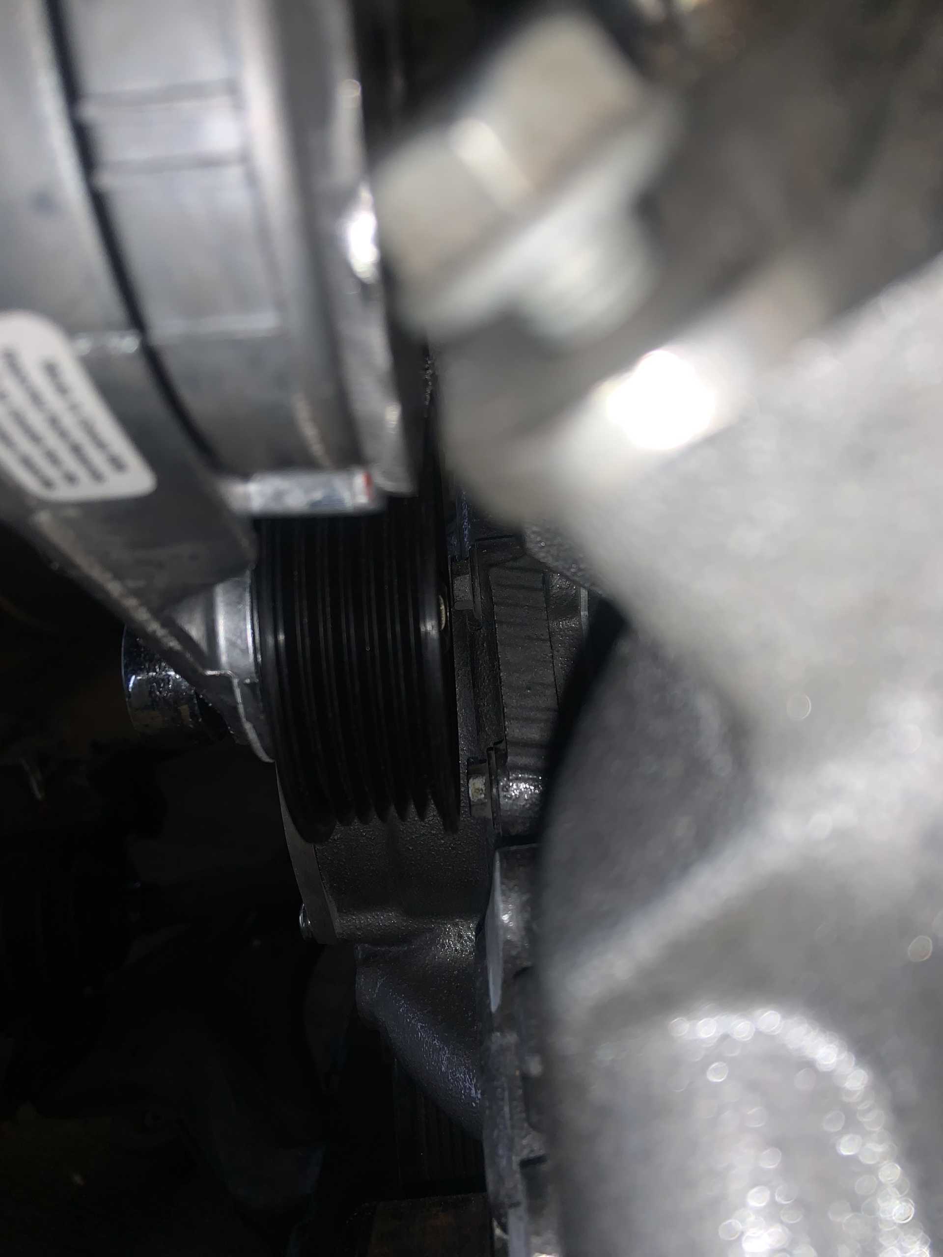
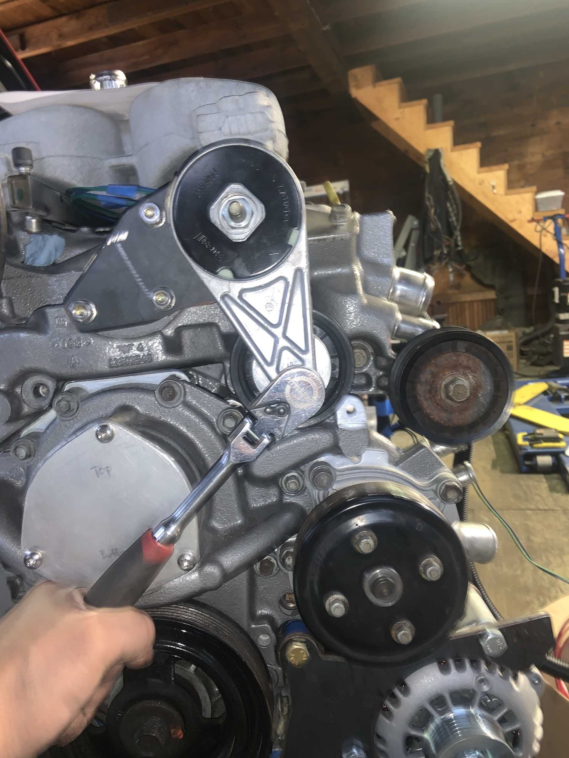
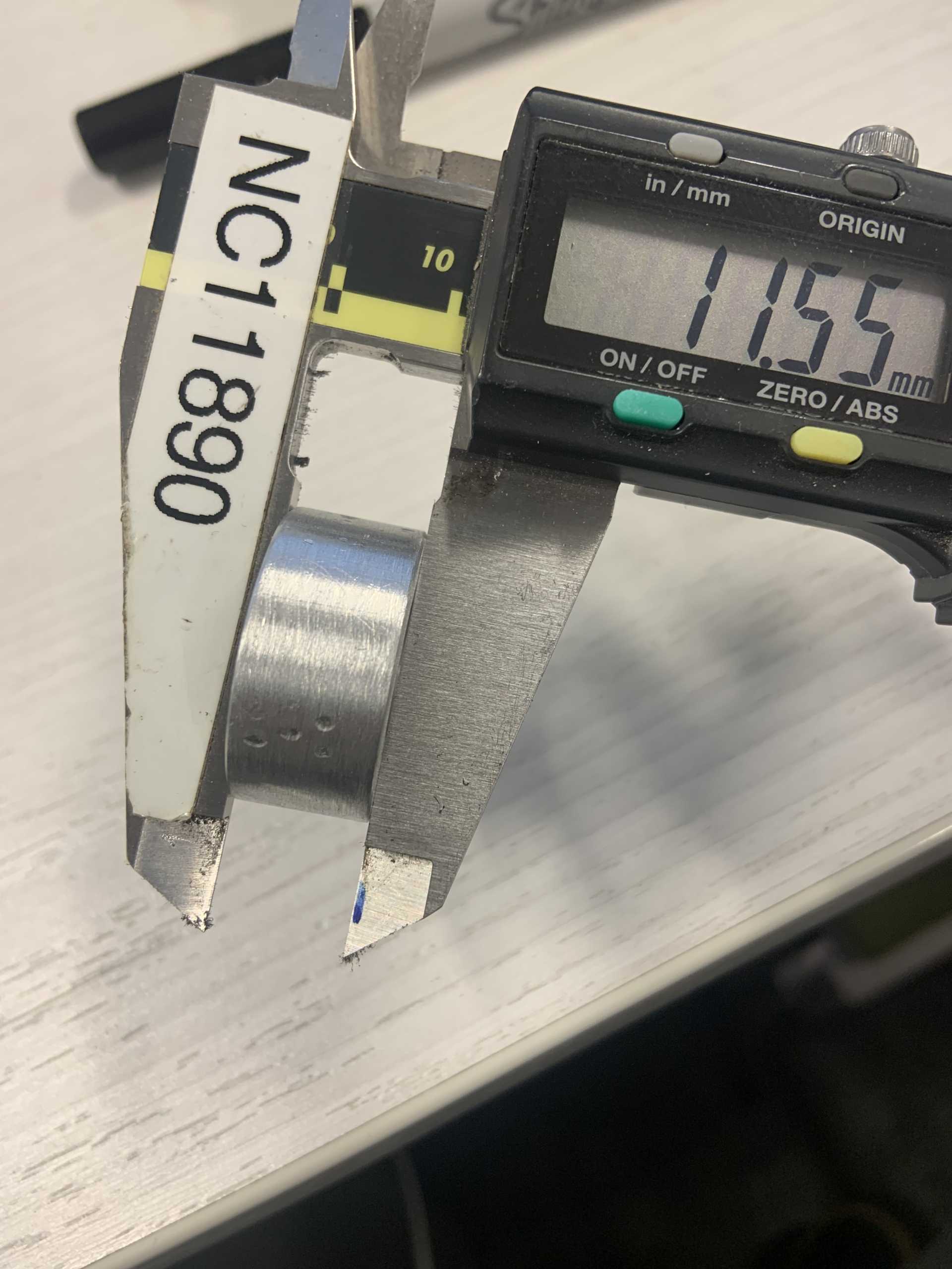
It can be seen below how close the upper timing cover bolt head is to the pulley. This pulley still needs to be spaced out an additional 2.90mm, so I will have to change the clocking slightly to allow the pulley to not cover that bolt. It is right at the edge of the pulley so it shouldn't take very much at all.
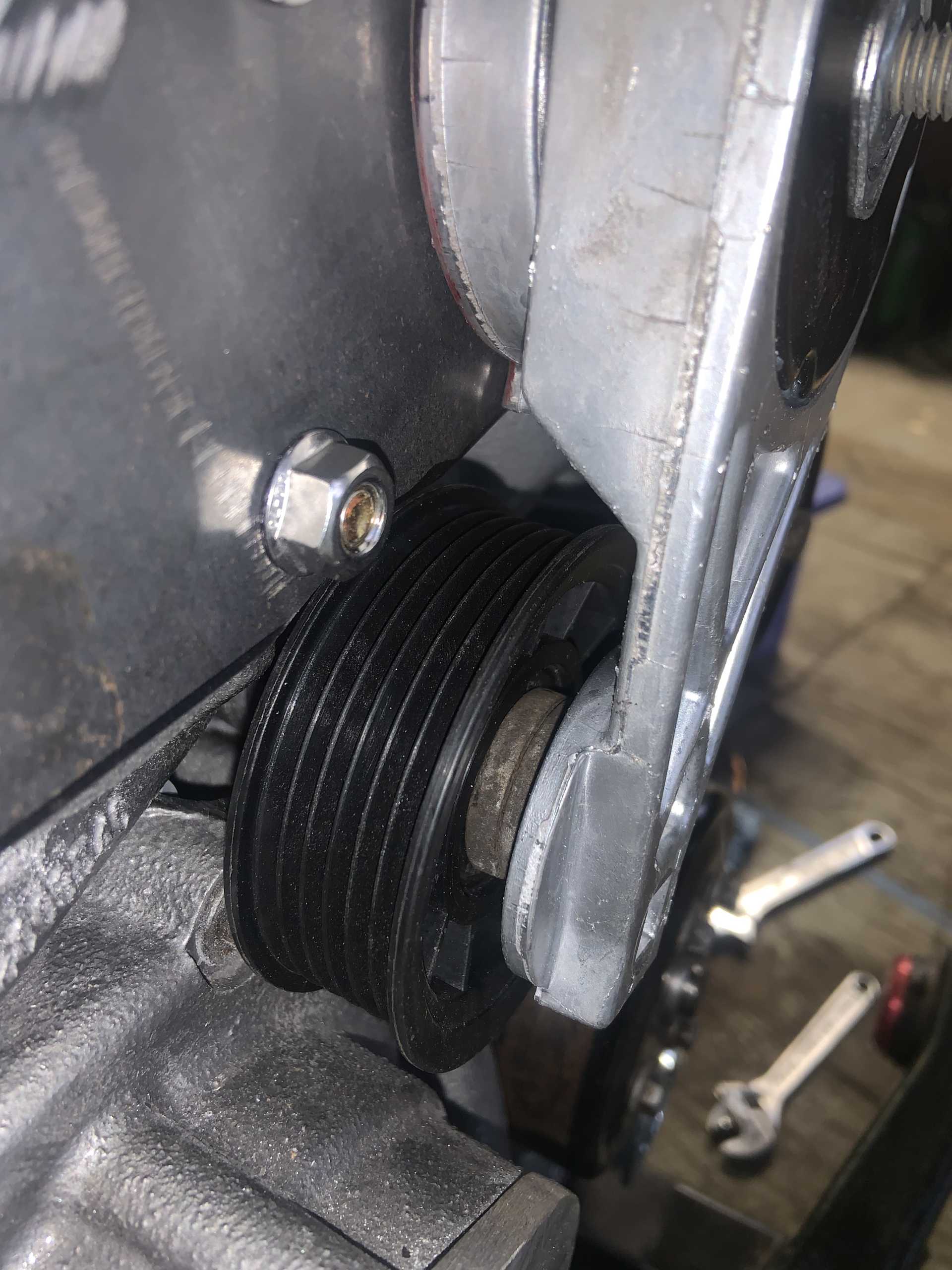
Here is the current spaced off tensioner pulley, I am using the strut bolt washers, it is spaced out about 5/16" currently and just needs a little more. Probably will end up at 7/16" spacing. You can also see the offending bolt head poking out from behind the pulley. Won't take much to clear it.
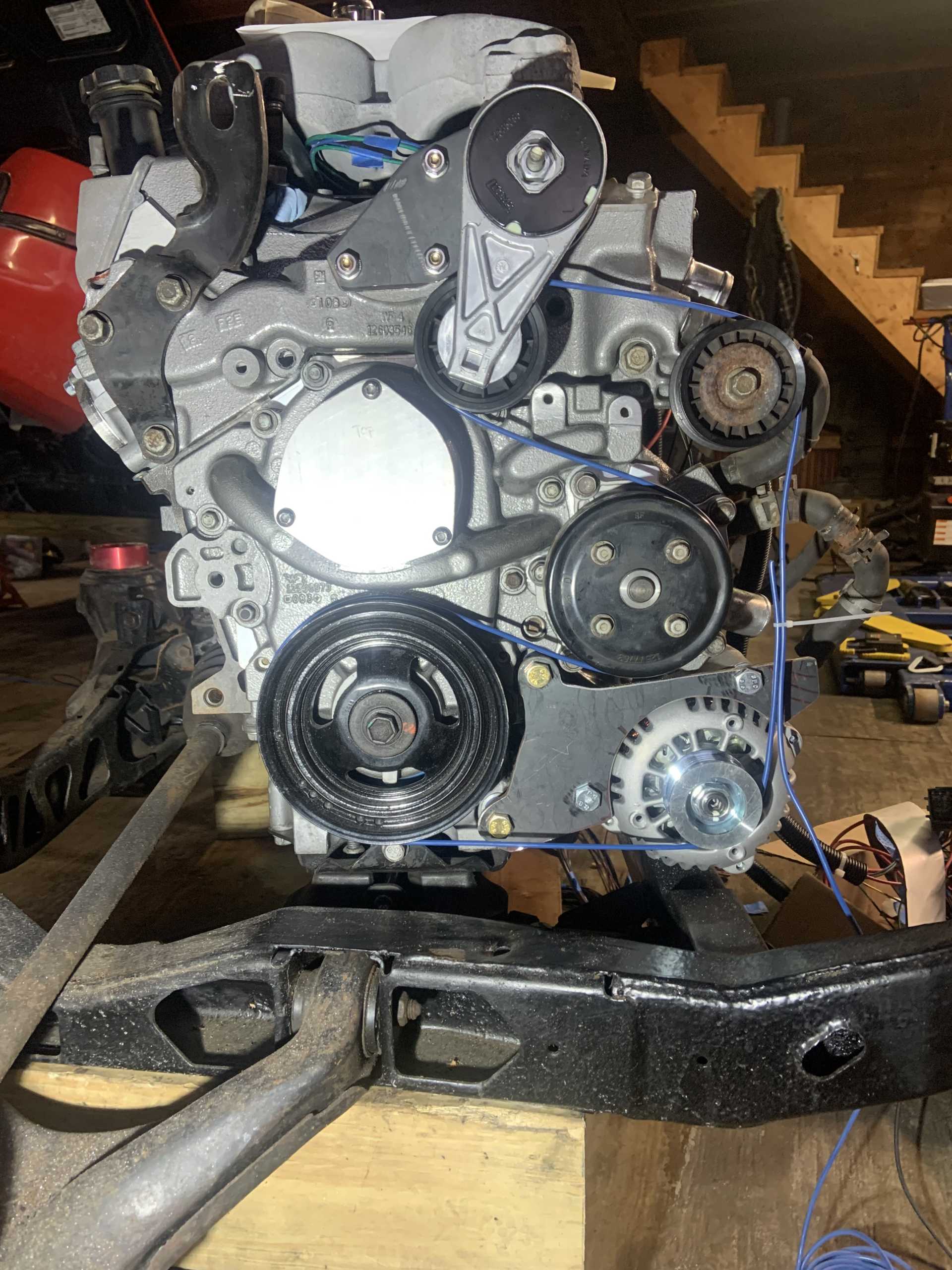
Tensioner has good range, it can go even farther too and still be tensioning. I wanted it to have a lot of range to make belt changes easy.
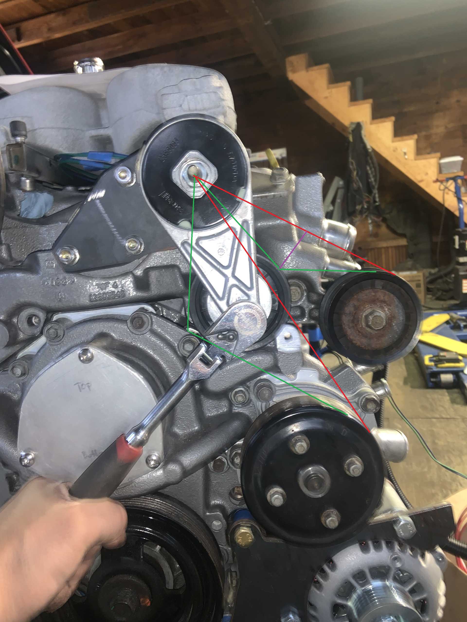
Here is an edited image of above, the green lines are showing the tangencies of the belts and pulleys currently, the red lines are showing how much farther the pulley can rotate and still be reducing belt length. The tangencies relative to the upper right idler pulley are the limiting factor in how much more it can tension, and the purple line depicts how much farther the tensioner can still rotate and be useful. In other words, clocking the pulley slightly should give me no issues with not having enough tensioning.
Belt routing.
I could still fill the coolant with where everything is
But I think I am going to make a new fill where I will weld some SS tubing to the plate and then the bung to the tubing to get it in an accessible location.
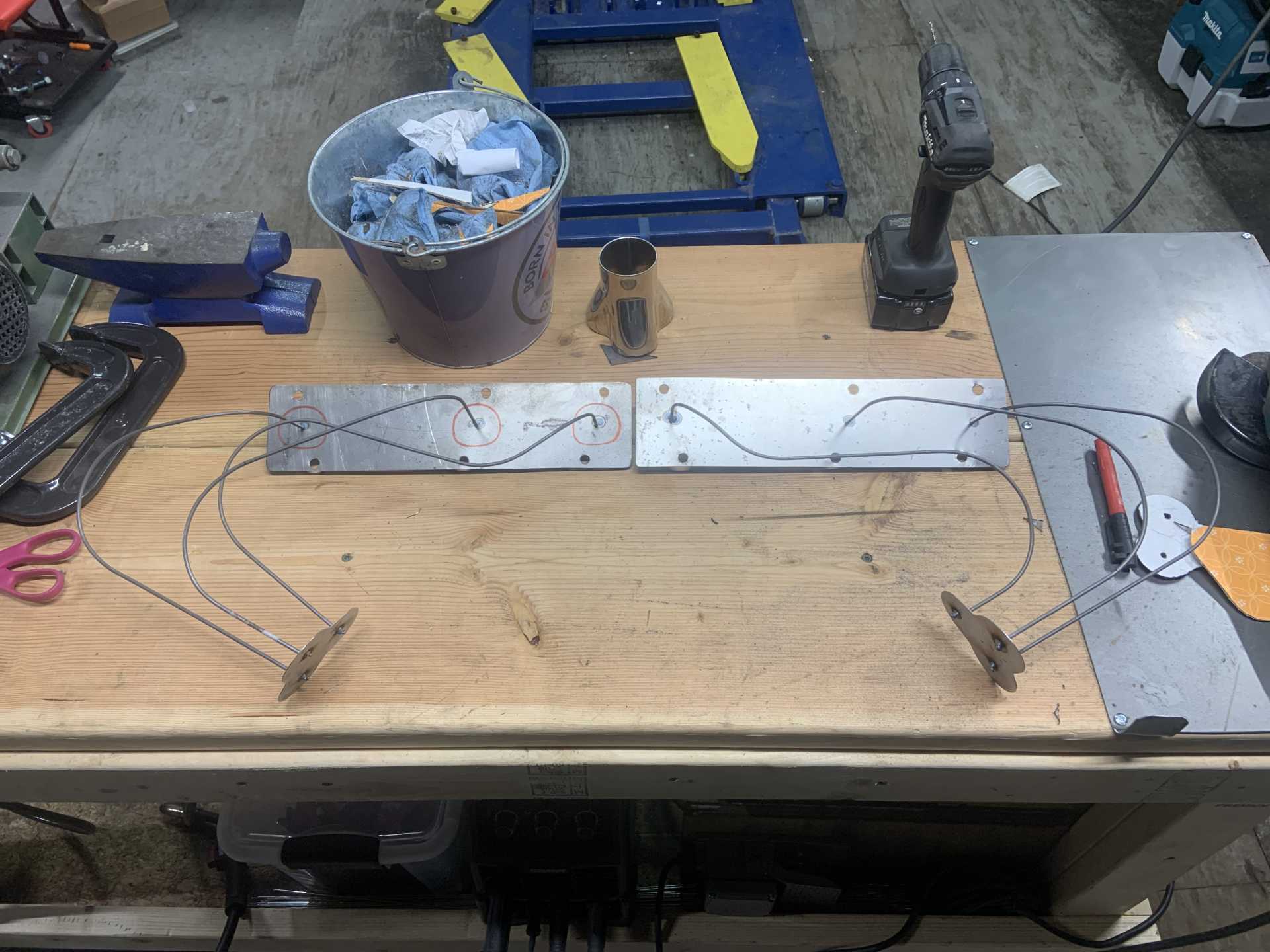
I also made some brackets out of SS to weld into the engine bay, they are sized to accept a press fit M6 nut. I made some fuel line clamps out of high temp plastic too, I drilled holes for the lines and then when they are cut in half with the band saw it creates the clearance to clamp down on the lines.
Parts have been coming in, I am on a roll.
[This message has been edited by zkhennings (edited 02-18-2023).]
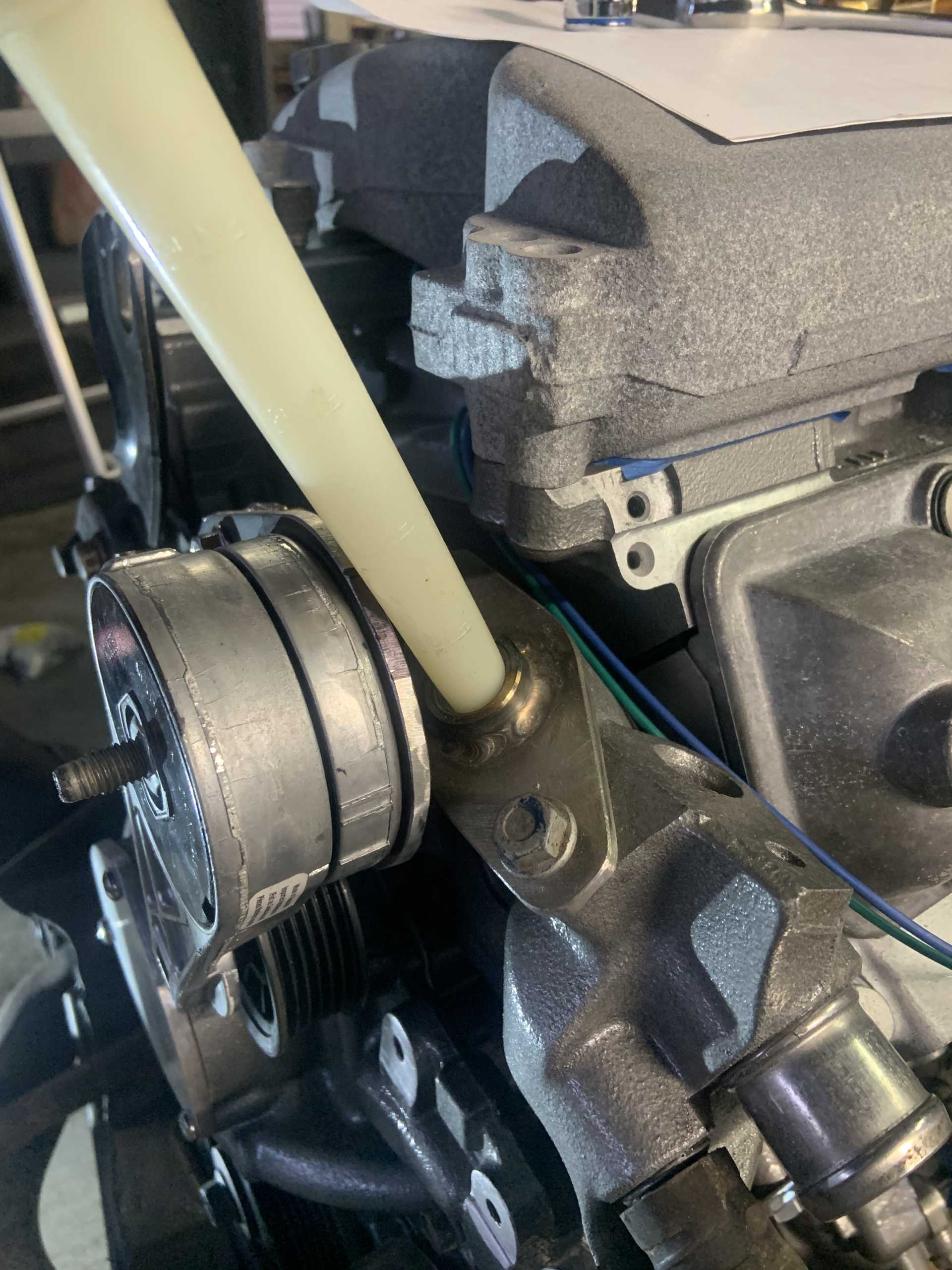
Tapped the heater outlet for 1/2" NPT, did not need to be drilled out or anything.
It was close to the valve cover so I cleaned it up. It probably could return to parallel and still clear fine. I just want to be able to pull the valve cover without much fuss.
I checked out having the TB upside down and learned it will interfere with the shift cables. So original orientation it is. Going to need an offset reducer and go down to 3" tubing as the shift cables are a little too tight to the 4" elbow.
3D printed a centering bushing for the tensioner pulley.
Made an aluminum spacer for the tensioner pulley.
Trimmed an offending bolt head down.
Fit check.
Welded a stiffening rib to keep the tensioner bracket from flexing.
Dogbone CAD while engine is still in the car.
Decided to make it easily removable by adding a bracket to the lift bracket.
I made slices where I bent the 3/16 sheet metal to make it bend precisely. Welded those up.
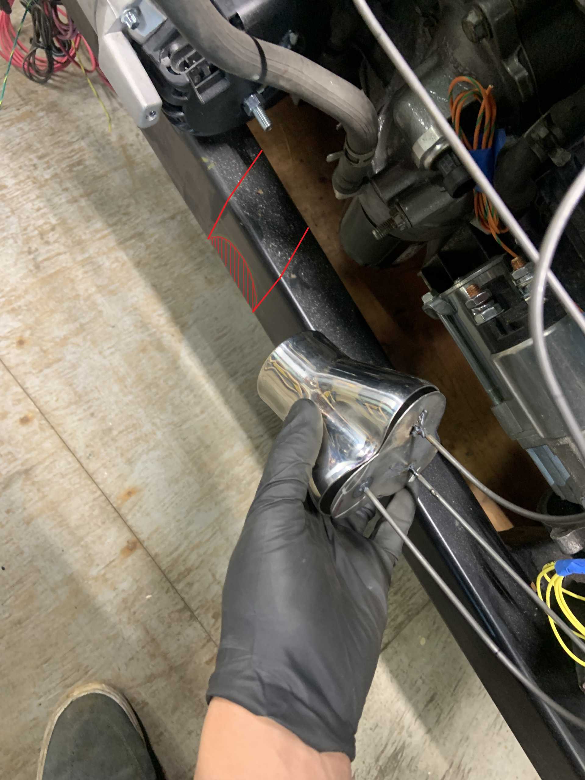
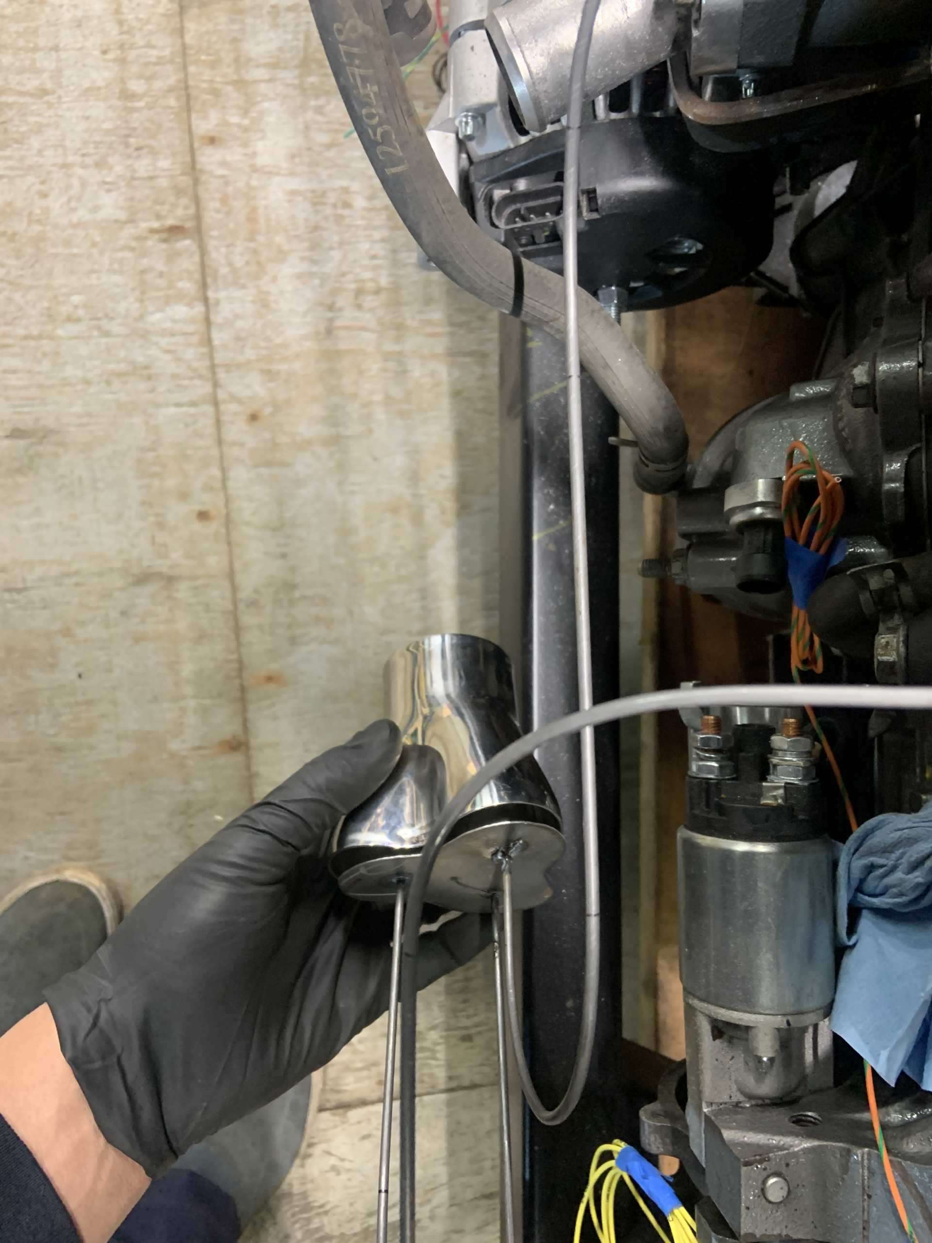
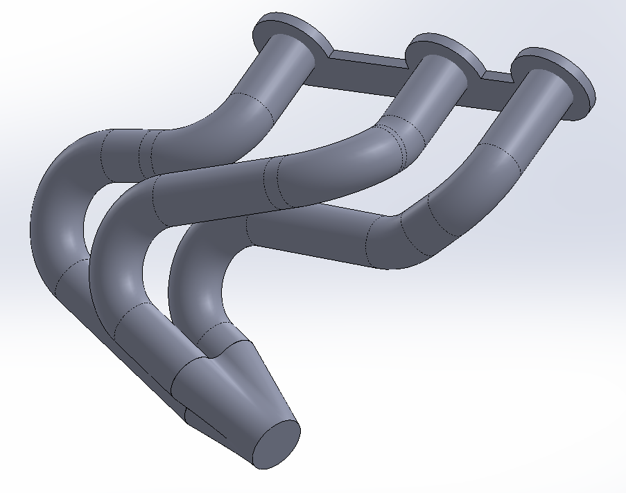
I have been working on the header design and mock up. Here are my mock ups. I used them to determine what angle the collector needs to be at relative to the block.
Here they are on the motor.
The firewall side header needed to be removed before I could adjust the collector angle properly.
Starting the final tasks before it is ready to go back in for the last time.
Finalizing the CAD for the headers, I will make a cardboard outline form for final test fit before making them. I have been able to make them equal length in the CAD, they are 22" primaries. Not as long as the 28" I hoped, but it is a good compromise of all things considered.
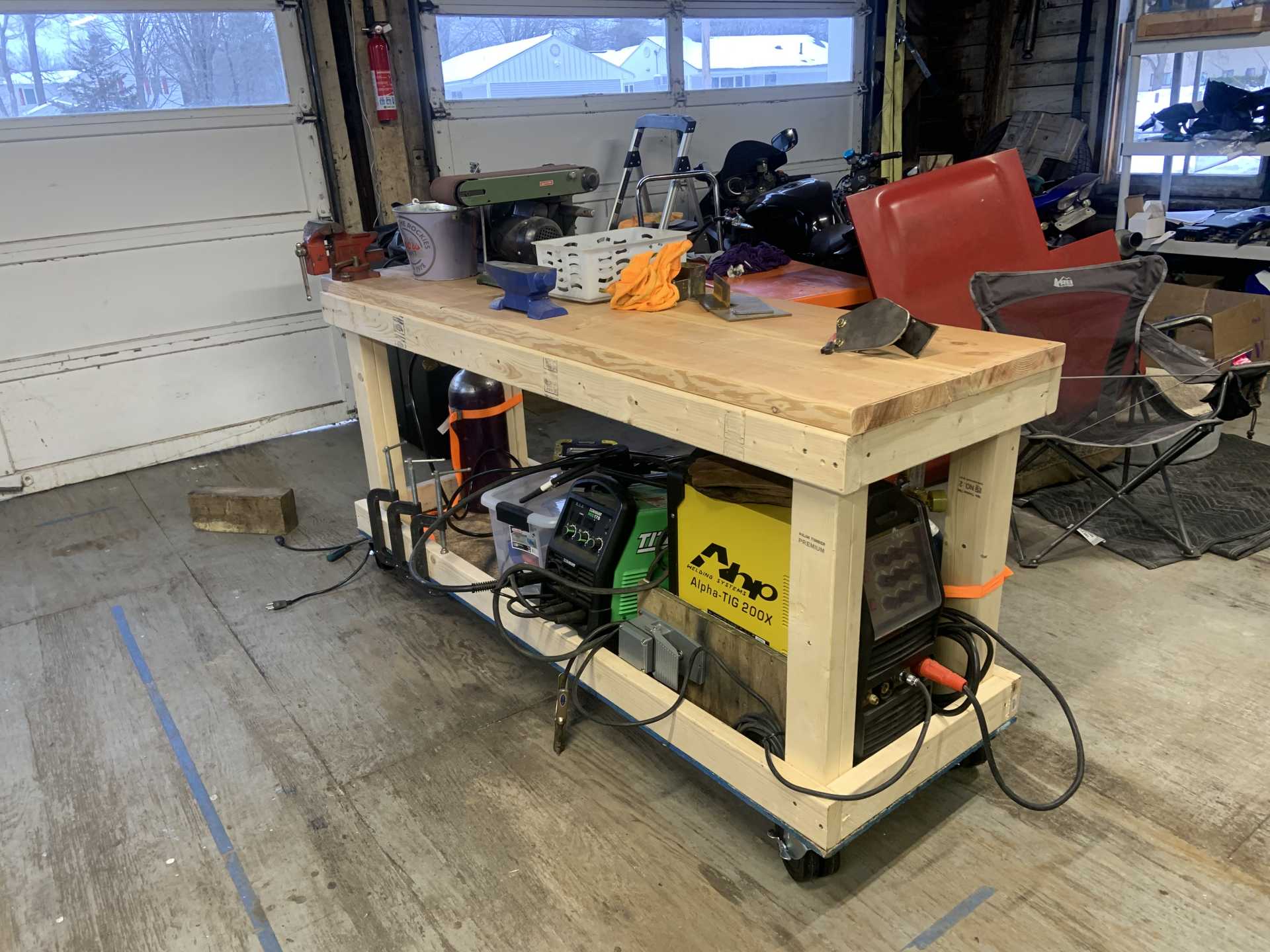
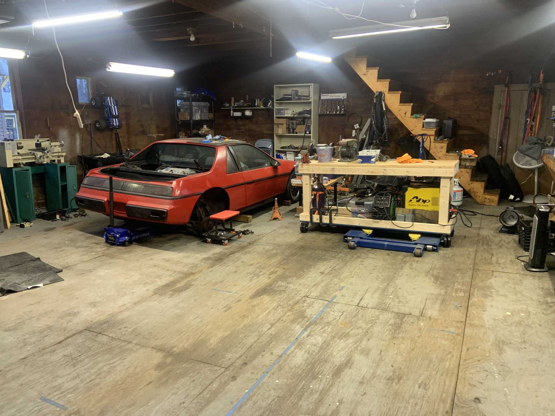
And some side things, I made a fabrication table so I can make messes near the garage door.
Took a mini haitus to go on vacation and do some side work on a coworkers WRX, pulled the motor and did all the valve clearances, timing belt, water pump, main seals, and a new flywheel and clutch. Doing an STI now but getting back to the Fiero.
To deal with the interference with the 4" Silicone elbow I was using for the throttle body in previous pics, I found this offset reducing coupler. It reduces from 4" to 3" and also has a center to center offset of 1/2". I think it will work out great. I also ordered a bunch of 3" aluminum tubing to make the intake with a 3" - 4" coupler to step it back up to the size of the air filter.
I then started a job I have been dreading, cutting off all the McMaster weld on studs I welded on back in the day, and also cutting off and grinding down the remaining factory brackets. Also going to fix rust in the battery tray, pull the rear crash bar off and paint the inside of the frame rails, fix a couple minor spots of trunk rust, and see if there is any rust to fix behind the wheel liners in the rear. I bought a bunch of paints from Eastwood including some 2K paint to paint the engine bay a nice gloss black, and an interior frame rail paint kit with a whip and 360* spray nozzle to paint the inside of the frame rails thoroughly. Only got a couple pics so far as my phone died on me.
How it was:
Chopped off and ground down, this job sucked and covered my barn in metal dust.
Also removed the torque strut rods, open to advice on which gas shocks to replace their absence with. Might buy a little kiddie pool to make an electrolysis setup to de-rust the crash bars.
[This message has been edited by zkhennings (edited 04-19-2023).]
Been working on the wiring, it has been a lot of research and making diagrams to keep everything straight.
After figuring out what I was doing and making all my diagrams, I paired the harness down to the connectors I need, and trimmed any wires I will be replacing and labelled them to make it easier to see where everything was.
Sorry, I know this is kind of old, but I was curious what you were going to do with the fusible links. I noticed one of the wires there still has it on there. I can't recall how many wires on the Fiero (either L4 or V6) have it, but I was thinking of replacing all of the fusible links as my daughter works through her car (and later when I redo my V6 Fiero in the winter). I thought it might just be easier to simply buy an aftermarket fuse pod with (however many I need) a specific number of modern fuses... makes it easier to see if I need to trouble-shoot. Just curious what you're going to do with them?
I was either planning to keep them or get new ones to replace them, from my research, fusible links only blow when there is sustained overcurrent, which is probably why they are used for the starter and other things that can pull a massive inrush current. If you sized a fuse to not blow in the same location, it would end up being way too large for the sustained current the fusible link is designed to allow.
It does look like there are specific special fuse boxes that accept a fusible link style fuse, but I will probably just replace the fusible links on an as needed basis with new fusible links. They are cheap, and they are also very unlikely to ever blow unless you have a massive short.
That's a good point, I suppose it's not something I really need to be concerned with, I've never had one fail... I just like having things like this all in one spot.
EDIT: If like you, I'm going to be going through it anyway... but I'll leave well enough alone and just be sure to identify where specifically they are.
Thanks!!!
[This message has been edited by 82-T/A [At Work] (edited 04-20-2023).]
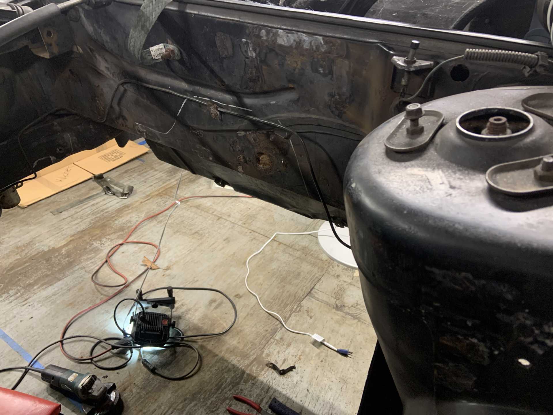
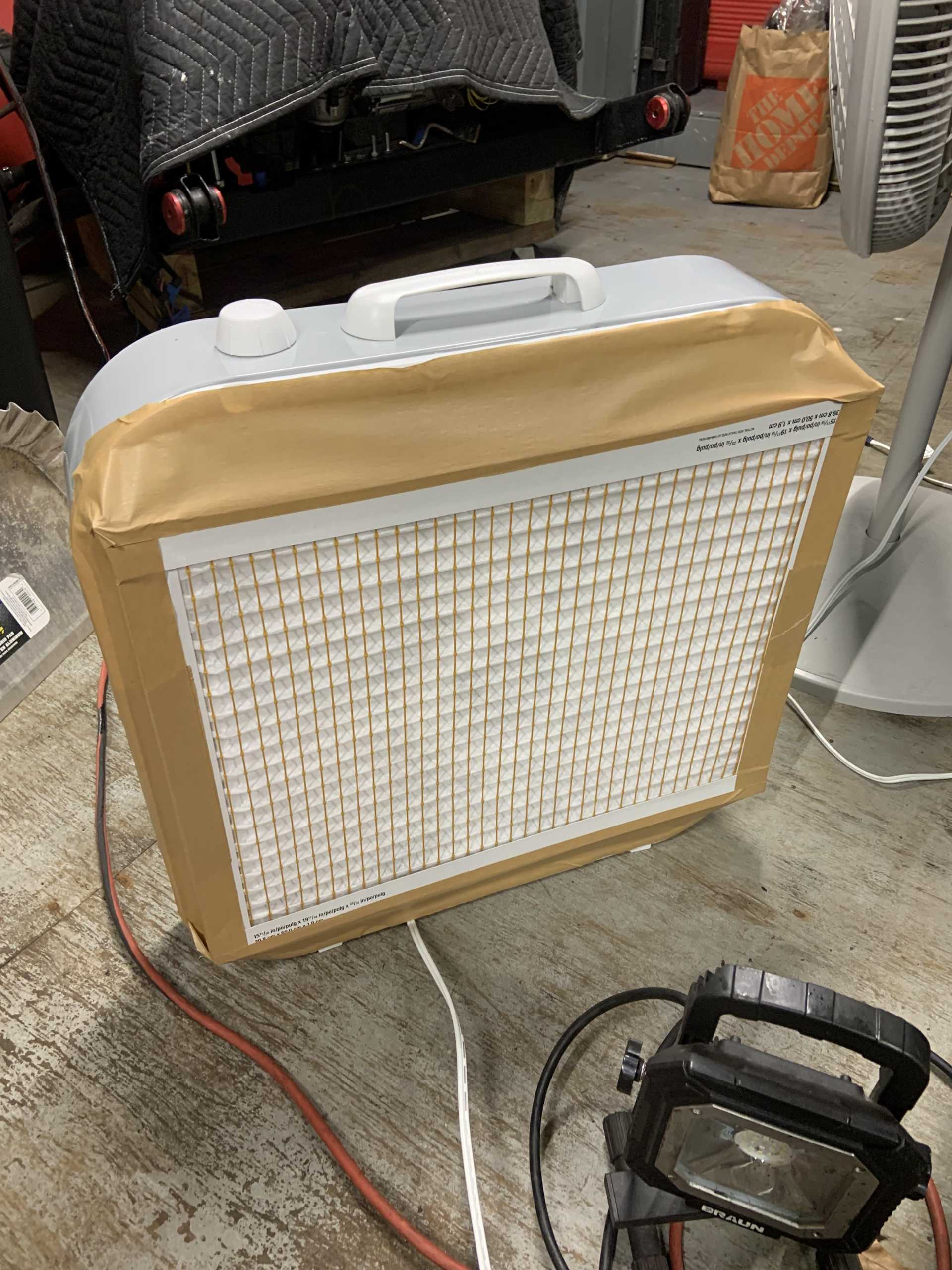
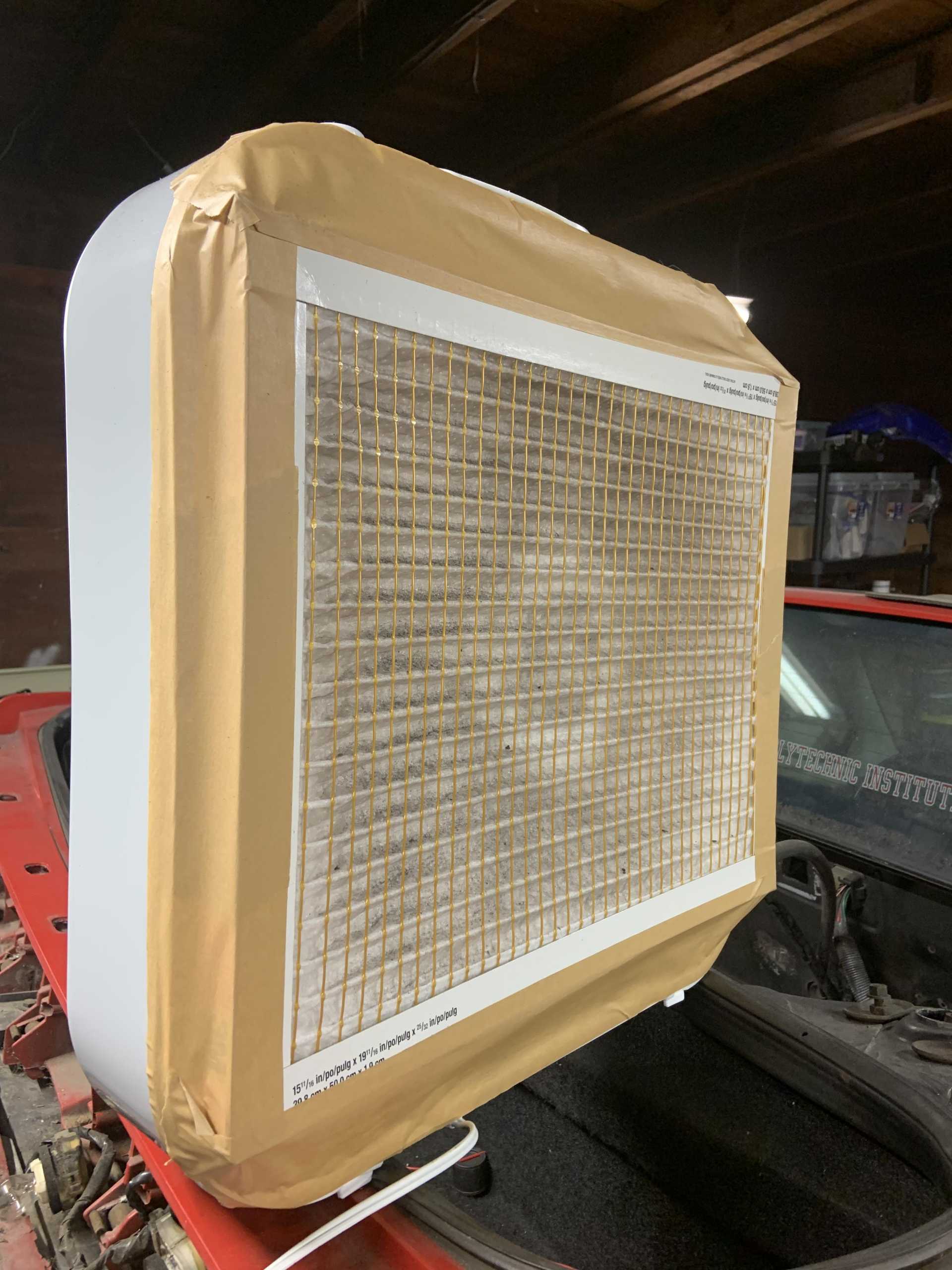
I bought a box fan and taped an HVAC filter to it, it has been doing a decent job trapping grinding dust and preventing it from landing on everything in my garage.
After a few min of grinding...
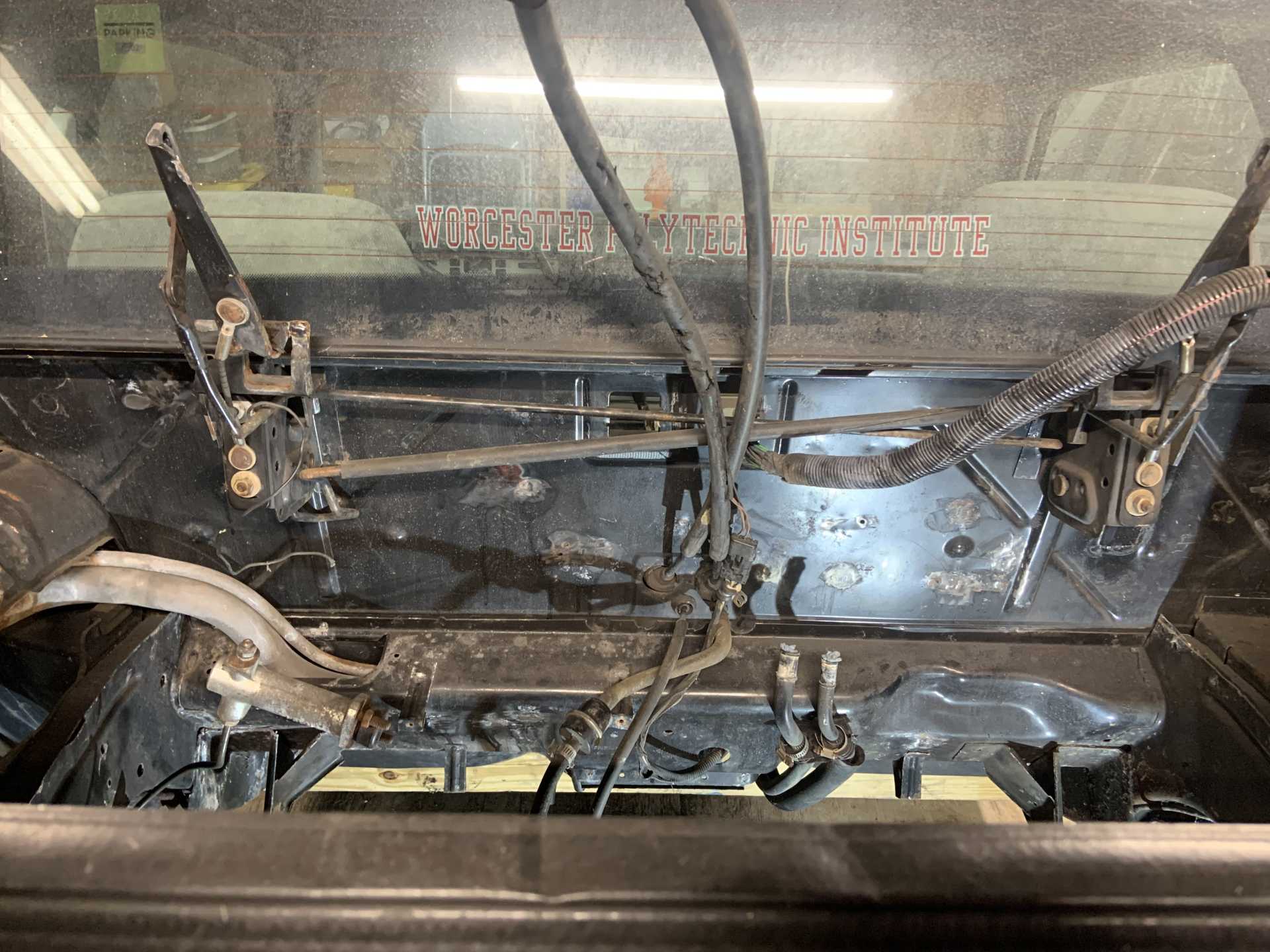
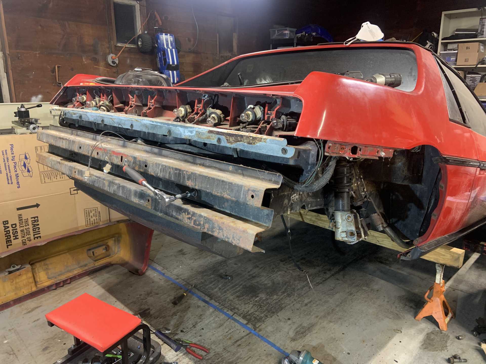
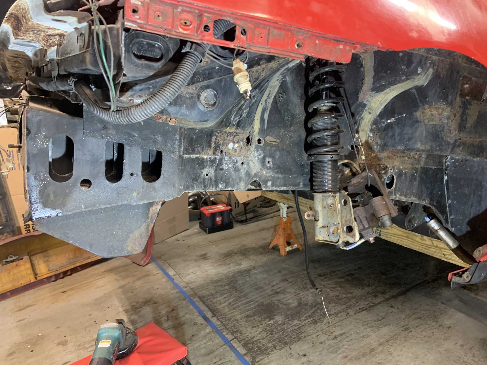
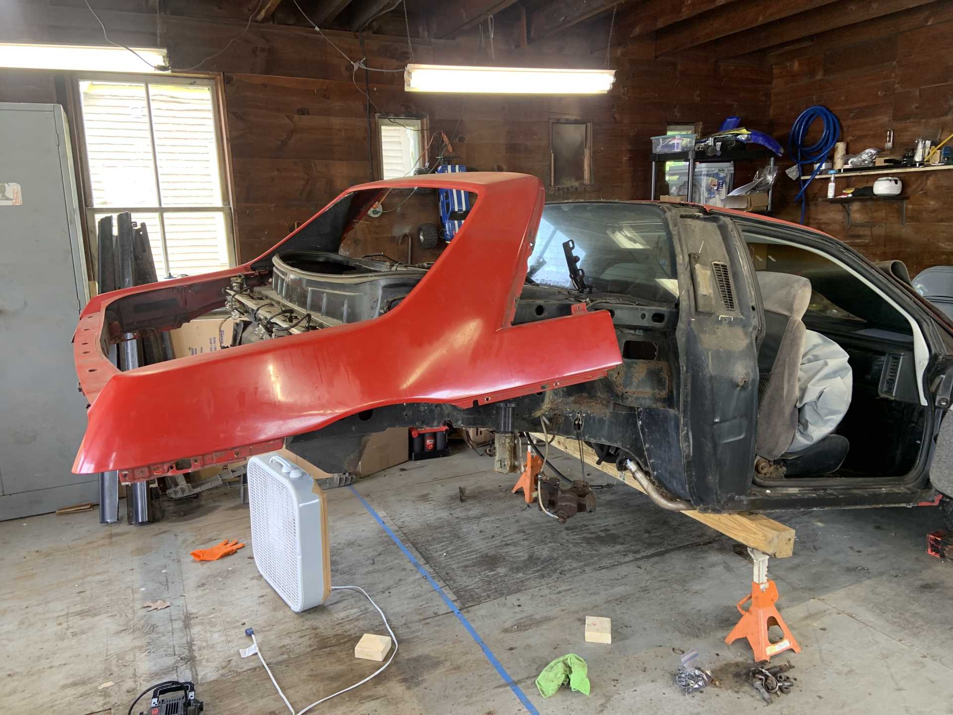
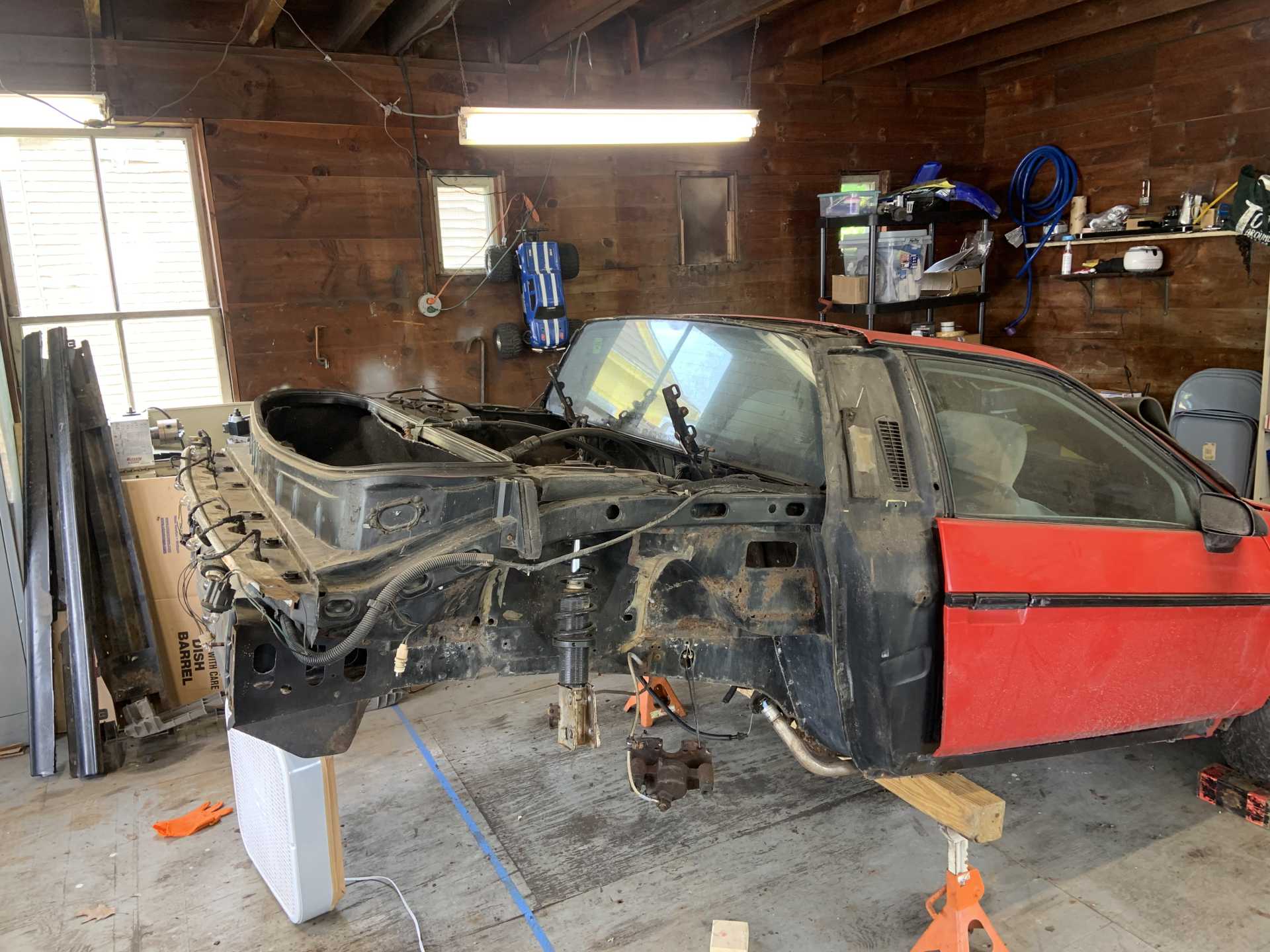
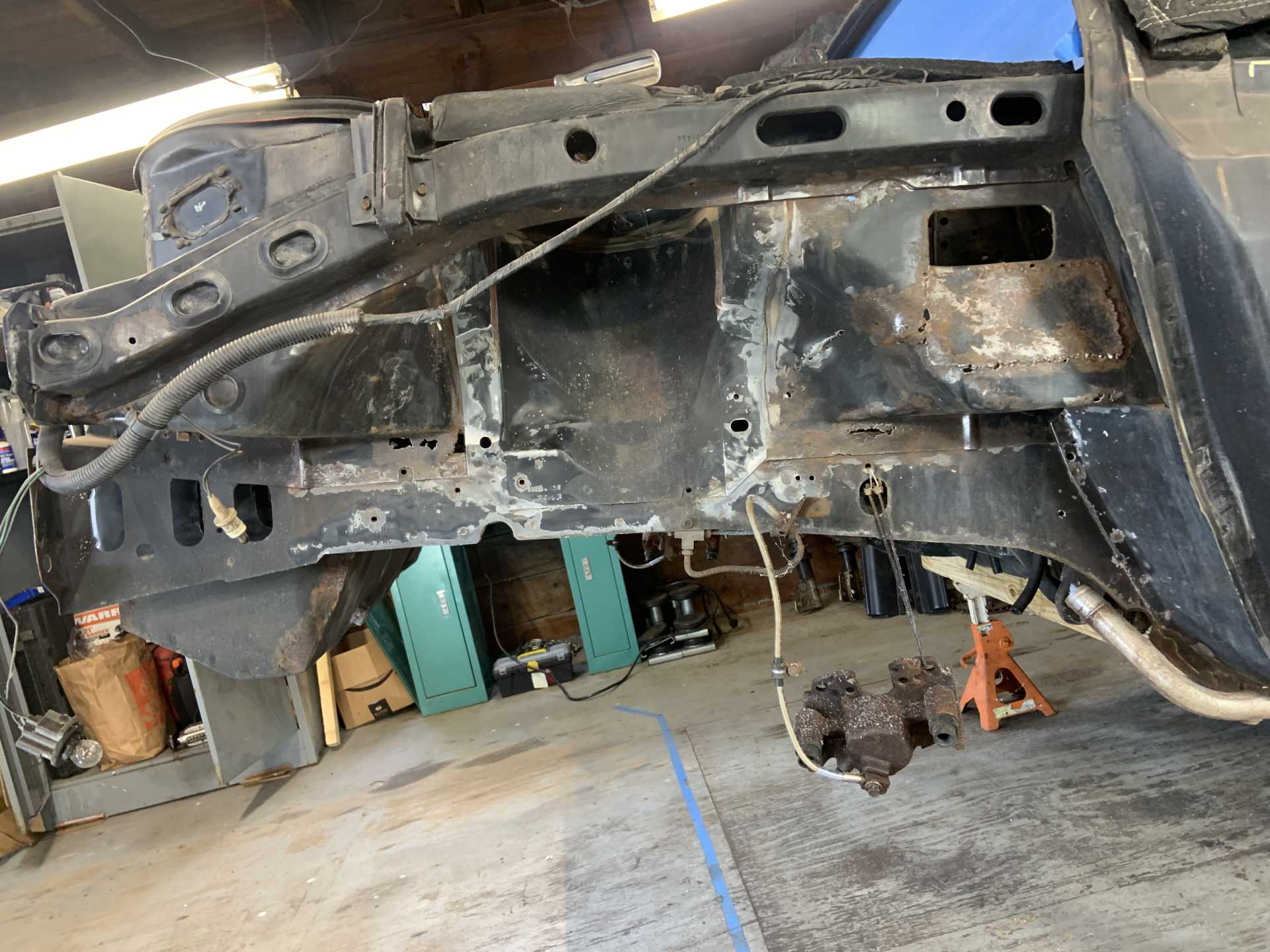
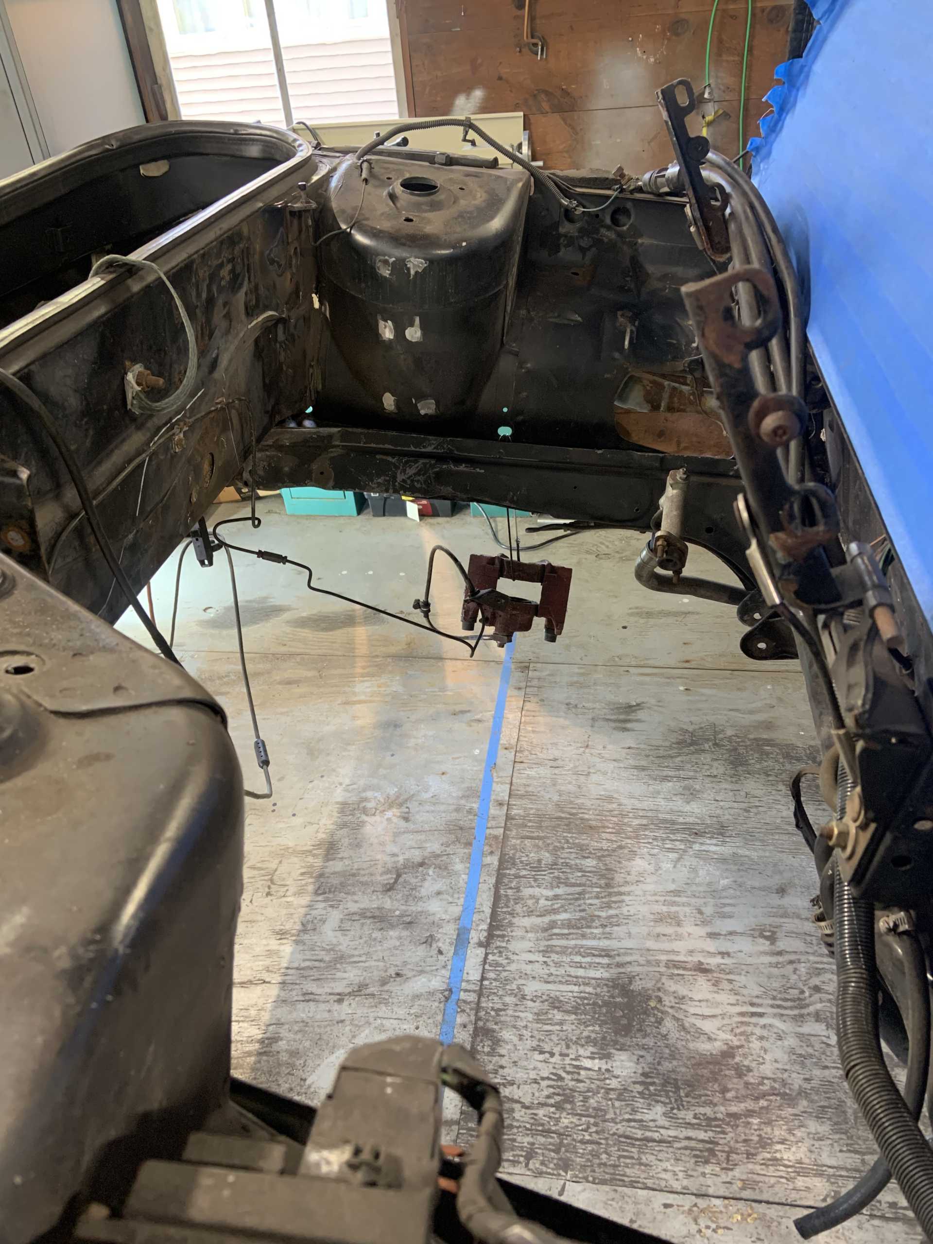
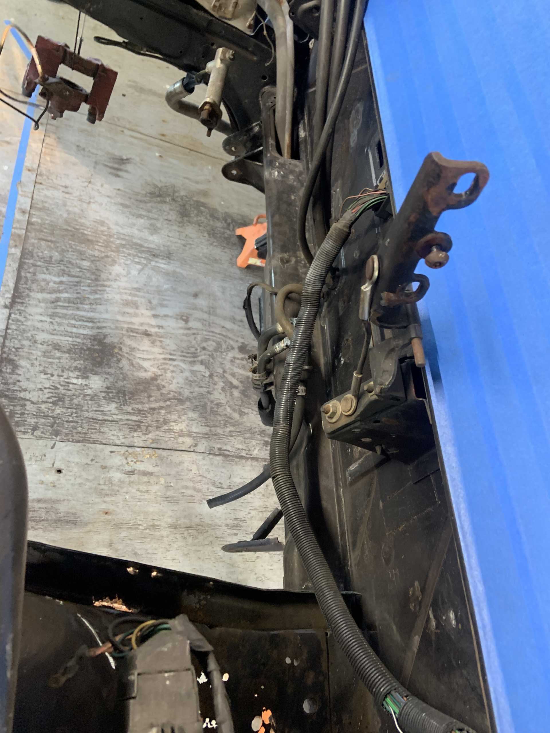
By now it is solid brown. Been exploring for rear end rust to fix, started to take the rear end apart.
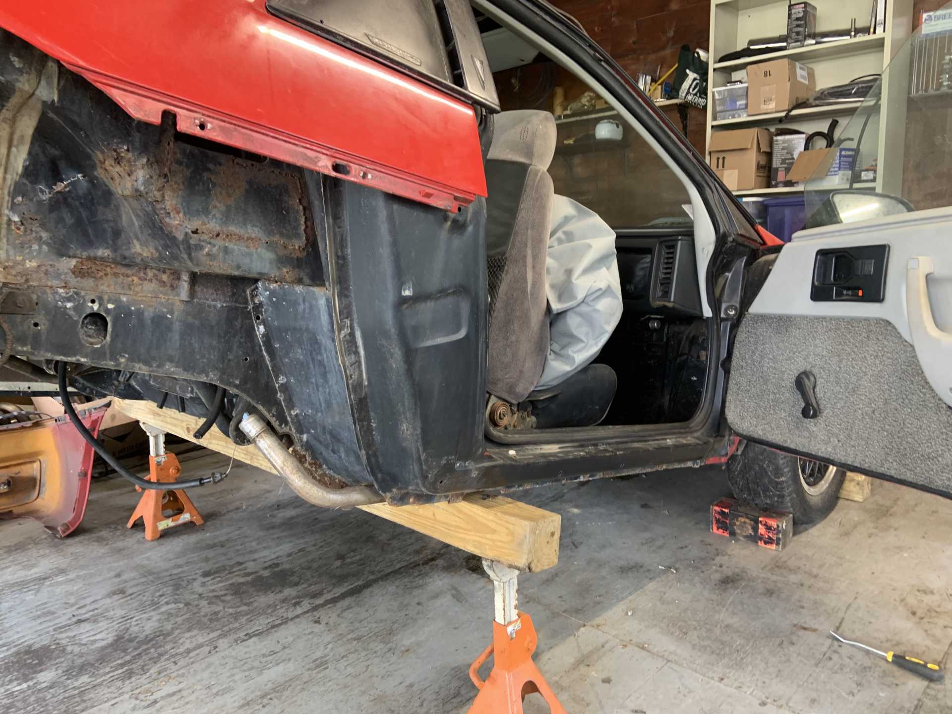
Well there is enough going on and there's no better chance than now to repair all the little spots, so I started taking the rest of the rear end body off. Rockers look great.
This was a pain to do alone, definitely will need a friend to put it back on.
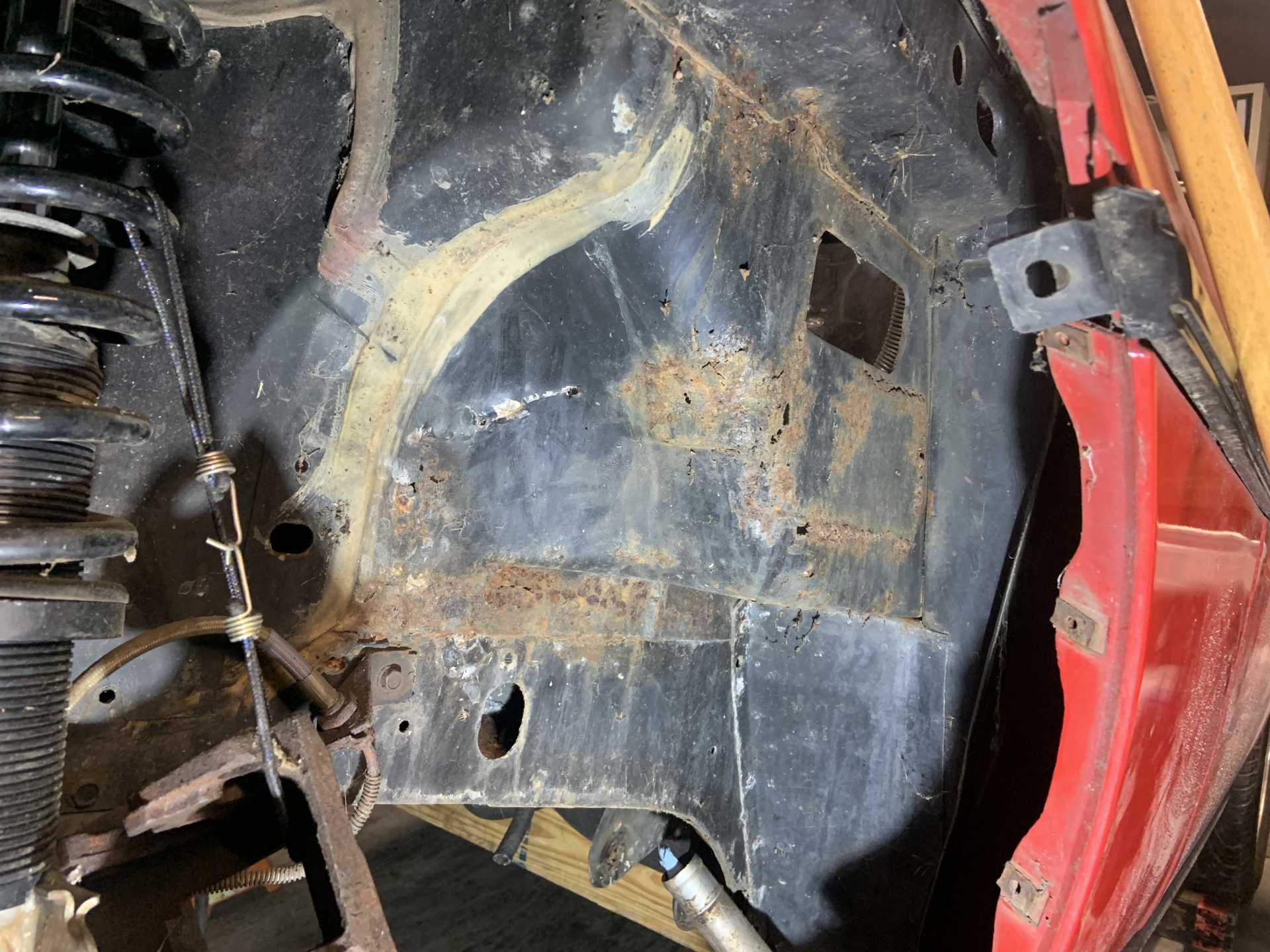
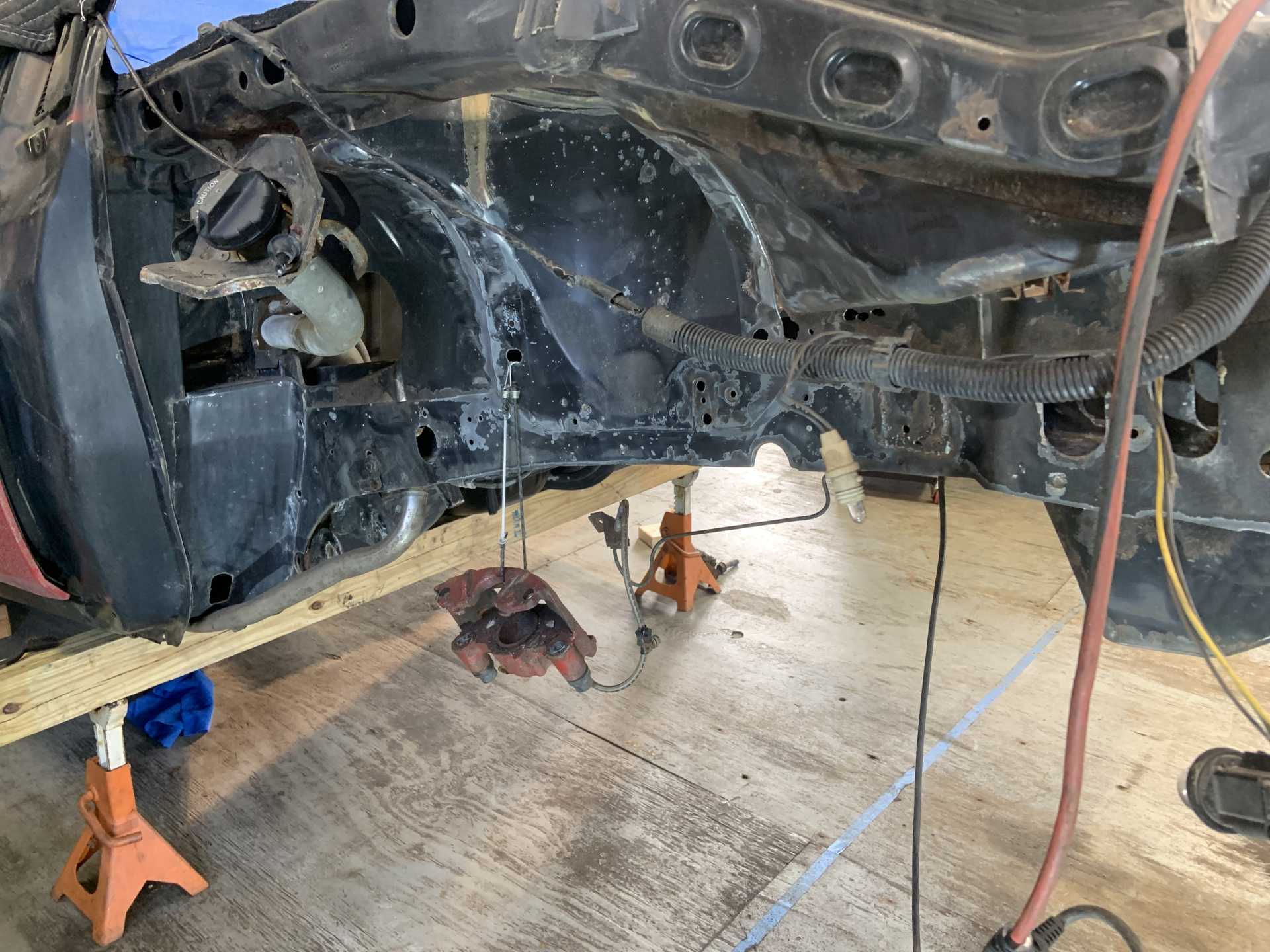
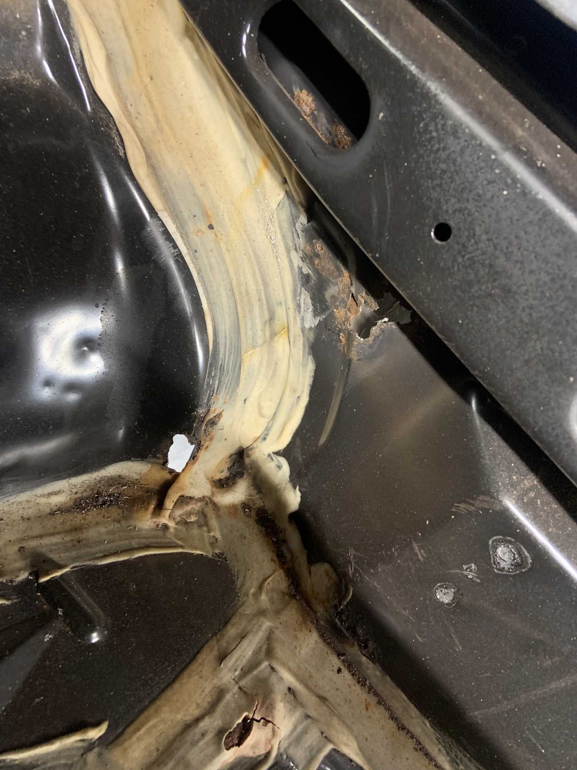
Went ham with the angle grinder with a wire wheel on it to discover all that can be discovered.
Few spots in the trunk I did not get the chance to get to yet, will need to use the die grinder with a wire wheel to fit in these tighter areas.
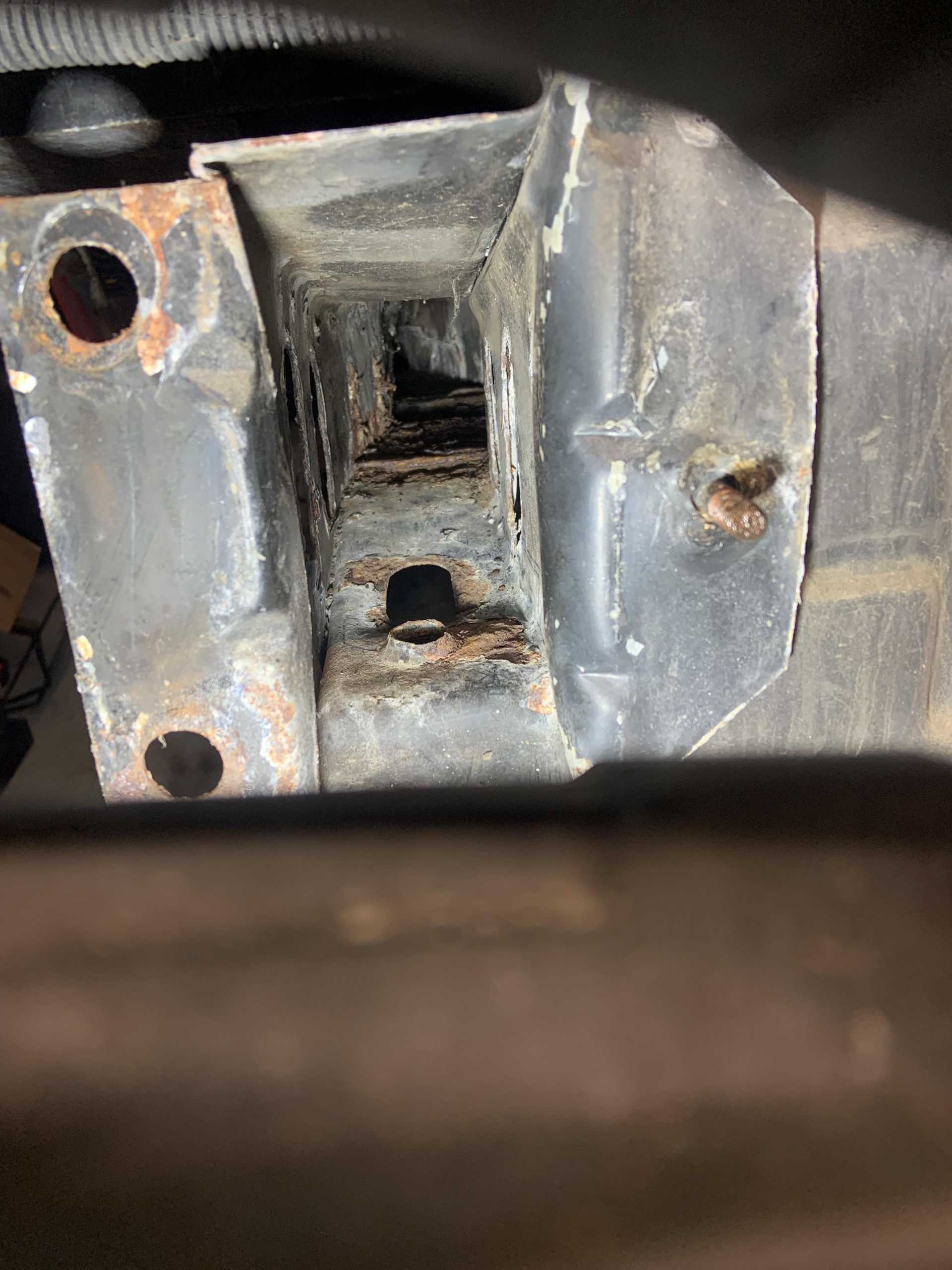
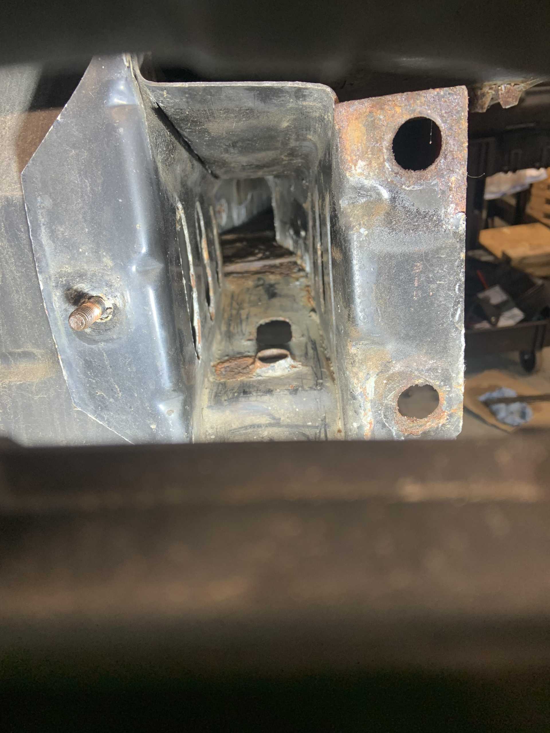
Plan is to start cutting bad sections out and welding in fresh metal, it is not too bad overall. I will paint in the upper and lower frame rails, got a bunch of Eastman products to paint everything with. I do think I am going to chop out the areas where the cradle bushings sit against the underside of the lower frame rails, it is going to be annoying to weld it all upside down so I may chop out the sides of the frame rail in the same area for welding access. Don't really want to, but can't afford weak welds in this area. The whole battery area is getting chopped out, and the rest will just be patches.
lookin good, doesnt look bad at all. Just a few spots need some love, youll knock that out in no time. Nows the time to make it a fast back , nice rc truck
Yea maybe a day or two of cutting grinding and welding. I did order the SWAG table mount kit for my harbor freight handheld bandsaw to turn it into a table mounted one, can't wait to use it and not have to cut all the new bits out with an angle grinder. Check it out. Mounts with just a couple screws if you want to take it off and use it handheld style. Expensive but everyone says it's perfect. They make them for a bunch of different bandsaws.
Funny you bring up the RC car, all my buddies just bought Traxxas cars randomly at the same time this week, I have been getting my brushless Associated MT10 going again as the steering servo was broken and the spur gear was stripped. The one on the wall is a 1/8 scale Associated nitro truck with a 0.5in3 motor which is enormous for an RC, it makes like 3hp. Got a 1/10 scale nitro truck too, swapped in a wicked high power motor back in the day and blew through a diff almost every time I used it. Swapped back to stock motor after I had spent almost $300 on diffs lol. Would wheelie through first, shift into second in the wheelie and wheelie through the whole second gear (only has two gears). Ported the stock motor before swapping it back in and it makes decent power, only baby wheelies though . Love the nitro but the brushless trucks just break way less because they weigh less, no transmission to mess with, and starting a hot nitro motor everytime you flip it upside down and stall it is a huge pain. The little nitro 2 strokes scream though, I'll get them running again soon if the buddies all stick with RC for more than a week hah. Also have an absolutely stupid little 1/18 scale replica Subaru that I put way too much money into in college, it's like 8" long and does around 80mph, absolutely uncontrollable with the throttle trim all the way up but when I used to rip it around the indoor bball courts in college people couldn't believe how fast it was.
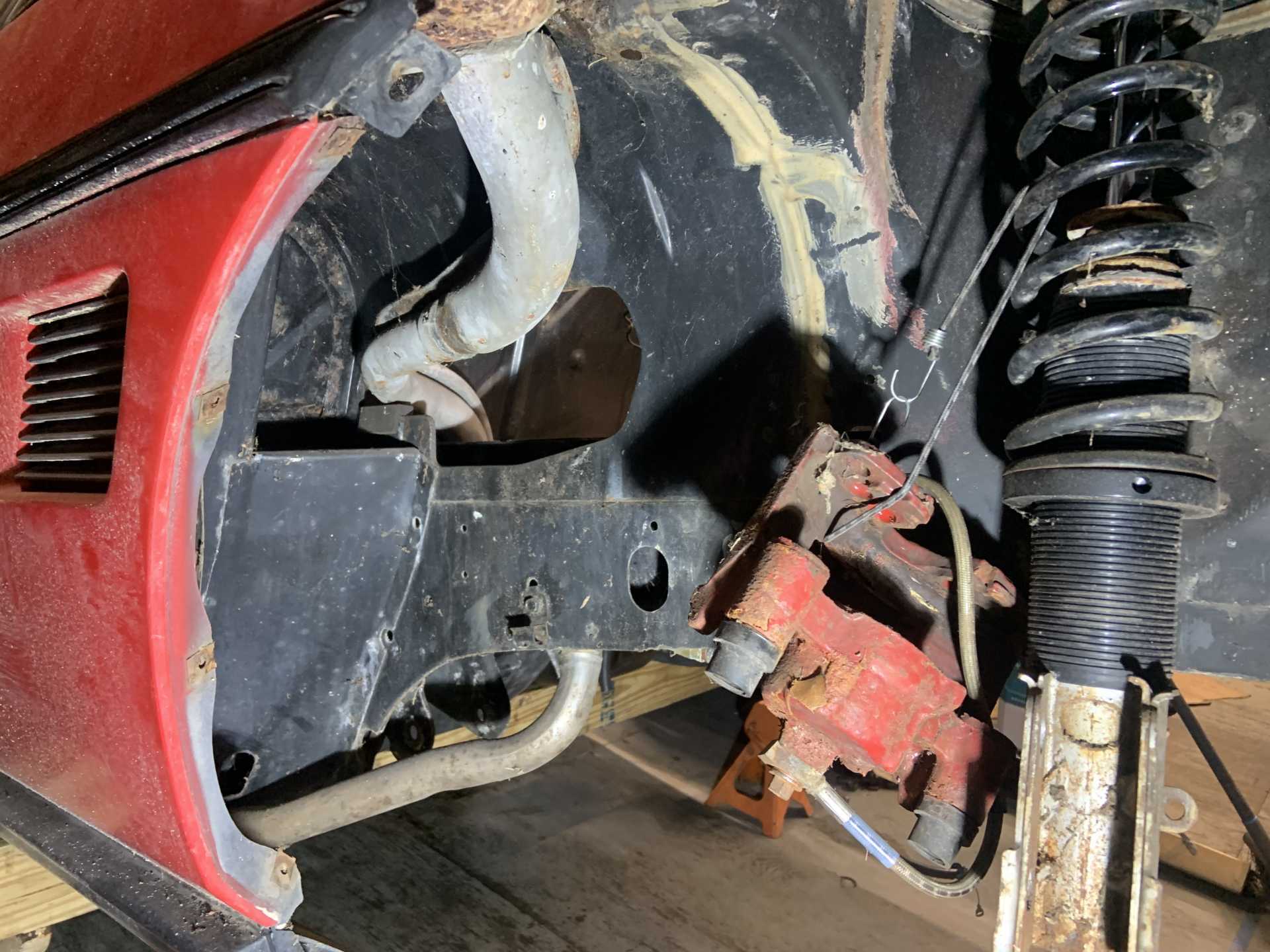
I am very amused at the fact that you've completely disassembled the entire rear-end, and yet there's the rear brake calipers suspended with a coat hanger... all by themselves. Hahah...
The frame looks pretty decent... you really lucked out there. We don't get a lot of rust down here in Florida, but some of the cars that we would see from say, New York or somewhere like that, the frames are totally rotted out. You can always tell because there's a Buffalo Bills or Jets sticker on the back of the Fiero.
My Fiero (my 87) came from Chicago... but it only spent a year there, and then the guy took an overseas job for over 6 years. He took it out of storage, had a shop take care of everything (change all the fluids), then my uncle bought it... so it only had 43k miles by the time I got it in 1996 in Northern Virginia. It spent the rest of it's life in Florida, so absolutely no rust. But I did see some pitting on the suspension components, specifically, the bracket that the upper control arm attaches to... but it was still very solid.
My daughter's car (an 85 4 cyl) seems to have come from North Dakota. It's pretty decent, surprisingly... but does have some rust in the trunk, which I'll have to address.
This car was from MA and it had been barely driven since 1990 when I bought it in 2010, and it was stored indoors. There was almost no rust when I took the body off on page 1 of this thread, but then I did lots of snow drifting in Worcester MA when I was in college and that definitely took a toll. The paint on these things is super easy to take off with the wire wheel, I’m not surprised that many of them rust badly.
I have a can of POR15 to treat metal areas that were rusty but don’t need to be replaced, then I have an interior frame painting can from Eastwood, has a long flexible tube with a 360* spray nozzle at the end to paint inside frame rails and rockers. Going to use it on the upper and lower frame rails. I also have a quart of 2 part epoxy primer I will shoot everything with, and then some 2K gloss black spray paint to shoot the engine bay with over the epoxy primer. All Eastwood products. Should be pretty bulletproof, they make really good stuff. I will get some rubberized undercoating product to shoot in the wheel wells and frame areas over the epoxy, I used it on the cradle over POR15 in the past and it held up for many years.
Should be a huge improvement over the factory paint.
... I have an interior frame painting can from Eastwood, has a long flexible tube with a 360* spray nozzle at the end to paint inside frame rails and rockers. Going to use it on the upper and lower frame rails.


 , nice rc truck
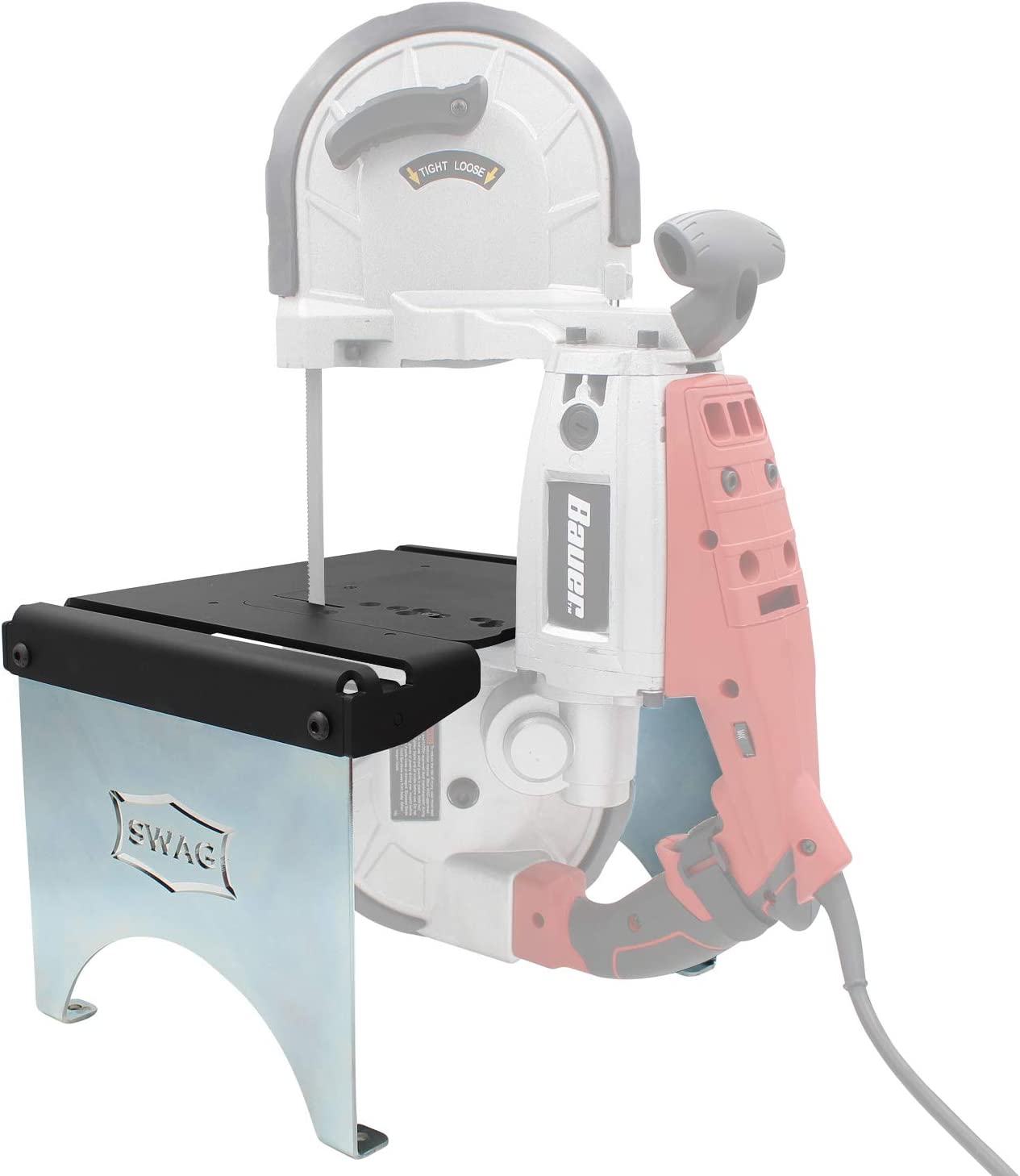
 . Love the nitro but the brushless trucks just break way less because they weigh less, no transmission to mess with, and starting a hot nitro motor everytime you flip it upside down and stall it is a huge pain. The little nitro 2 strokes scream though, I'll get them running again soon if the buddies all stick with RC for more than a week hah. Also have an absolutely stupid little 1/18 scale replica Subaru that I put way too much money into in college, it's like 8" long and does around 80mph, absolutely uncontrollable with the throttle trim all the way up but when I used to rip it around the indoor bball courts in college people couldn't believe how fast it was.


